

Page 1
DSL905E Series
User ManualUser Manual
User Manual
User ManualUser Manual
Version 1.0
Page 2

User ManualUser Manual
User Manual
User ManualUser Manual
© Copyright
May 2001
Version 1.0
The hardware described in this manual is owned by Aztech Systems Ltd and is protected by
international copyright laws. You may not remove the copyright notice from any part of the
hardware or any copy of the written materials accompanying the hardware.
In addition, no part of this manual may be reproduced or transmitted, in any form or by any means,
electronic or mechanical, including photocopying, recording, or information storage and retrieval
systems, for any purpose other than the purchaser’s personal use, without the prior written
permission of Aztech Systems Ltd.
• Virata is a registered trademark of Virata Corporation.
• All other company or product names are trademarks or registered trademarks or service
marks of their respective owners and are hereby recognized as such.
Disclaimer Statement
Aztech Systems Ltd specifically disclaims all warranties, either expressed or implied, including but
not limited to implied warranties of merchantability and fitness for a particular purpose, with respect
to the hardware, firmware, and the accompanying written materials. Aztech Systems Ltd reserves
the right to revise or make improvements to its product at any time and without obligation to notify
any person of such revisions or improvements.
In no event shall Aztech Systems Ltd be liable for any consequential or incidental damages,
including any loss of business profits or any other commercial damages, arising out of the use of
its product.
Product warranty does not apply to damage caused by lightning, power surges
2
or wrong voltage usage.
Page 3
User ManualUser Manual
User Manual
User ManualUser Manual
Safety Guidelines
This product is for use only in UL Listed computers.
Adhere to the following safety guidelines when using your unit to reduce the risk of fire,
electric shock and injury.
Understand all instructions in the manual. Follow all instruction labels found on the
!
unit.
Except for the power adapter supplied, the unit should not be connected to other
!
adapters/power supplies.
Never spill liquid of any kind on the unit.
!
Do not place the unit on an unstable stand or table. The unit may drop and become
!
damaged.
Do not expose the unit to direct sunlight.
!
Do not put any hot devices close to the unit as it may degrade or cause damage to
!
it.
Do not put any heavy object on top of the unit
!
Do not use liquid cleaners or aerosol cleaners. Use a soft, dry cloth for cleaning.
!
3
Page 4

Contents
Copyright .................................................................................... 2
Disclaimer Statement ..................................................................... 2
Safety Guidelines ........................................................................... 3
Introducing DSL905E ...................................................................7
1
1.1 Documentation ............................................................................... 8
1.2 Manuals/UI/Firmware Updates ......................................................... 8
1.3 Minimum System Requirements ....................................................... 9
1.4 Network Connections ...................................................................... 9
1.4.1 Single PC Configuration .................................................. 9
1.4.2 More than 1 PC Connections ........................................... 9
Before You Begin ..........................................................................10
2
2.1 Package......................................................................................... 10
2.2 Overview for DSL905E .................................................................... 11
2.2.1 Front View ..................................................................... 11
2.2.2 Rear View ...................................................................... 12
Connecting DSL905E ................................................................... 13
3
3.1 Verifying the Setup Connections ....................................................... 15
Configuring Your Ethernet Card ................................................... 16
4
Running DSLTEST ...................................................................... 18
5
Frequently Asked Questions ......................................................... 20
A
Troubleshooting Guide .................................................................24
B
Technical Specifications ................................................................29
C
C.1 Main Features ................................................................................ 29
C.1.1 ADSL/ATM Support ......................................................... 29
C.1.2 Encapsulation Support .................................................... 30
Page 5

C.1.3 Network Suppor t ............................................................ 30
C.1.4 Management Suppor t ..................................................... 30
C.1.5 Security Support ............................................................ 31
C.2 Platform Support ............................................................................ 31
C.3 External Connectors ........................................................................ 31
C.4 Built-In Pots Splitter........................................................................ 31
C.5 LED Indicators ............................................................................... 32
C.6 Environmental ................................................................................ 32
C.6.1 Temperature .................................................................. 32
C.6.2 Humidity ....................................................................... 32
C.7 System Requirements ..................................................................... 32
Page 6

Page 7

Chapter1
Introducing DSL905E
This section gives a brief introduction of DSL905E features and its
Congratulations on your purchase of DSL905E !
ADSL, which stands for Asymmetric Digital Subscriber Line, is the latest communication
technology that offers faster and uninterrupted Internet access.
DSL905E is an embedded solution that is OS independent. It can be connected to any
computer with an Ethernet/Fast Ethernet card or to a Hub/Switch. It has an Ethernet
connection that allows direct interface to any existing IEEE 802.3 LAN network, providing
instant broadband Internet access to LAN networks with minimum hassle.
To ensure the broadest customer reach, DSL905E features multiple data encapsulation
formats for DSL transport over ATM PVCs, including the widely supported ADSL protocols
RFC 1483 (MPoA), RFC 1577 (IPoA) and RFC 2364 (PPPoA).
It supports multimode - fully compliant with ANSI T1.143 Issue 2, ITU-T G.992.1 (G.dmt)
and G.992.2 (G.Lite) featuring Discrete Multi-tone (DMT) line encoding used by major ADSL
manufacturers, further guarantees interoperability with network providers worldwide.
specifications.
7
Page 8

User ManualUser Manual
User Manual
User ManualUser Manual
1.1 Documentation
DSL905E Series User Manual (READ THIS MANUAL FIRST!)
This user manual is a printed guide that comes with your ADSL package. Please refer to
this manual for setting up and connecting your router. It also contains the sections on
Frequently Asked Questions and Troubleshooting Guide.
DSL Router Commander Software Manual
1
The software manual is a softcopy guide that contains information on DSL Router Commander,
a User Interface (UI) that provides a simple way of configuring your router. A Glossar y
section is also included to describe the terms used in the manual.
For queries or problems encountered, you may refer to the Frequently Asked Questions and
Troubleshooting Guide found in the User Manual.
DSL905E Series Technical Manual
1
The technical manual is a softcopy guide that contains console commands and advanced
router configurations that are mostly intended for experienced users.
For queries or problems encountered, you may refer to the Frequently Asked Questions and
Troubleshooting Guide found in the User Manual.
ATMOS Console Commands Reference Manual
1
The reference manual is a softcopy guide that contains the details of console commands and
its functions. For any advance configurations, you may refer to it for their descriptions.
1.2 Manuals/UI/Firmware Updates
To ensure that you have the best of the product, continuous efforts are made to improve our
software. Our manuals, User Interface (UI) and firmware are being updated as and when
required. To make sure that you do not miss out any of our new updates, please visit
http://www.aztech.com/suppor t.htm for downloads.
1
These manuals are found on your DSL905E Series CD-ROM that comes with your ADSL
package.
8
Page 9
User ManualUser Manual
User Manual
User ManualUser Manual
1.3 Minimum System Requirements
Pentium® MMX 233MHz (or above) with Ethernet card (installed with TCP/IP Protocol)
A Serial Port (DSUB-9)
A CD-ROM Drive
For Single PC Connection
- Cross UTP CAT-5 Ethernet cable (direct connection to the router's 10 Base-T
Jack)
For more than 1 PC connections
Expand using Ethernet Hub or Switch
- To connect to the MDI port of your Ethernet Hub/Switch, please use Cross UTP
CAT-5 Ethernet cable.
- To connect to the MDIX port of your Ethernet Hub/Switch, please use Straight UTP
CAT-5 Ethernet cable.
1.4 Network Connections
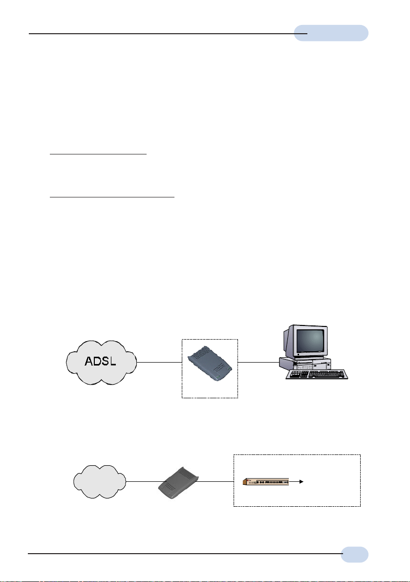
1.4.1 Single PC Configuration
DSL905E
1.4.2 More than 1 PC Connections
ADSL
DSL905E
Ethernet
Hub/Switch
PC with Ethernet Card
multiple PCs with
Ethernet Cards
9
Page 10
Chapter2
Before You Begin
This chapter contains information that you need to know before setting up
DSL905E. It is important that you go through them.
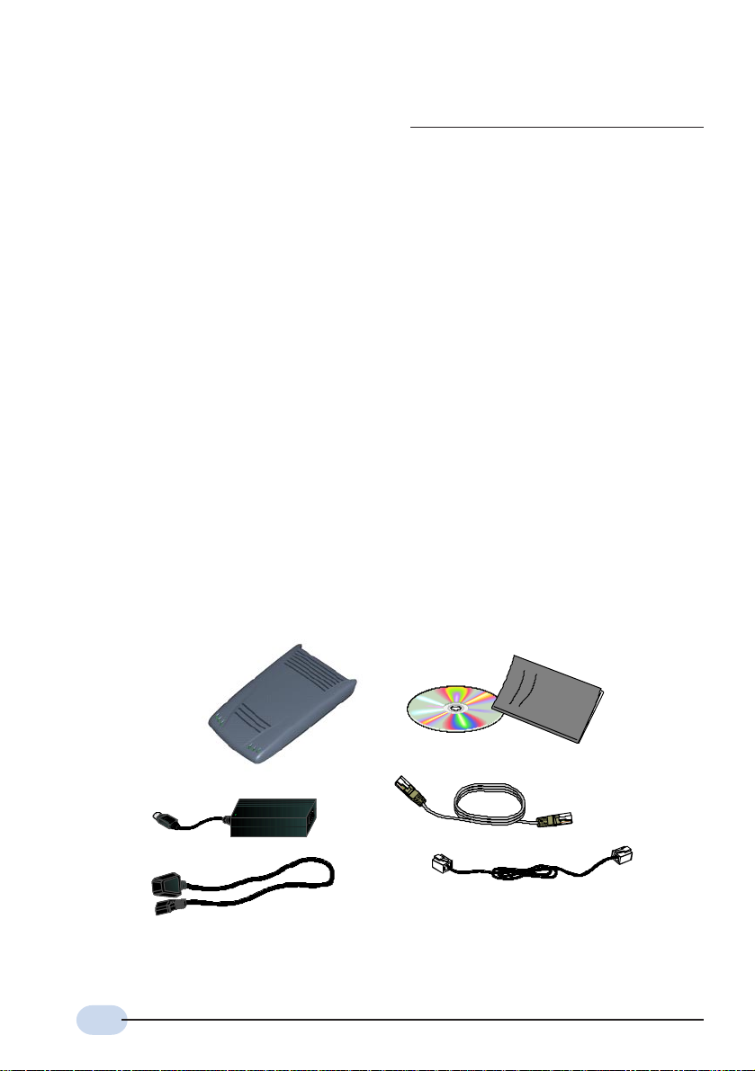
2.1 Package
Ensure that you have the following items in your router package. For any missing items,
please contact your dealer immediately.
DSL905E Series
DSL905E
Power adapter
(DC 5V)
Power cable
2
The telephone extension cable used for this router is a UL Listed Communication Circuit
Accessor y, minimum 26AWG.
10
CD-ROM
2
Telephone cable (RJ-11)
DSL905E Series
User Manual
Straight CAT-5 UTP
Ethernet cable (RJ-45)
Page 11

2.2 Overview for DSL905E
2.2.1 Front View
¬
User ManualUser Manual
User Manual
User ManualUser Manual
®
±
°
¯
¬ Power LED
Lights up when Power switch (at the rear) is pressed ON.
Ethernet Link
Lights up when the Ethernet cable (from your router to Ethernet Card) is connected.
® Ethernet ACT
Ethernet Activity: Lights up when the Ethernet is transmitting/receiving data.
¯ ADSL Receive LED
Lights up when the ADSL Line is receiving data.
° ADSL Transmit LED
Lights up when the ADSL Line is transmitting data.
± ADSL Link LED
Lights up when the ADSL link (from your router to telephone wall socket) is
connected.
11
Page 12

User ManualUser Manual
User Manual
User ManualUser Manual
2.2.2 Rear View
®
¬
¬ TEL
Telephone jack (RJ-11) to connect to the Telephone Handset.
±
°
¯
LINE
Telephone jack (RJ-11) to connect to the telephone wall socket (ADSL Line).
® CONSOLE
9-pin serial port for local network management.
¯ 10 BASE-T
10 Base-T Ethernet jack (RJ-45) to connect to your Ethernet card or Hub/Switch.
° DC5V
To connect to the Power Adapter that comes with your package.
± Switch
To power on or off the router.
O - indicates OFF position
I - indicates ON position
12
Page 13

Chapter3
Connecting DSL905E
This chapter contains information on the hardware setup of DSL905E.
Power off your computer or/and any connected devices before connecting
your router !
Please note the Ethernet cable types that are to be used for connections.
13
Page 14
User ManualUser Manual
User Manual
User ManualUser Manual
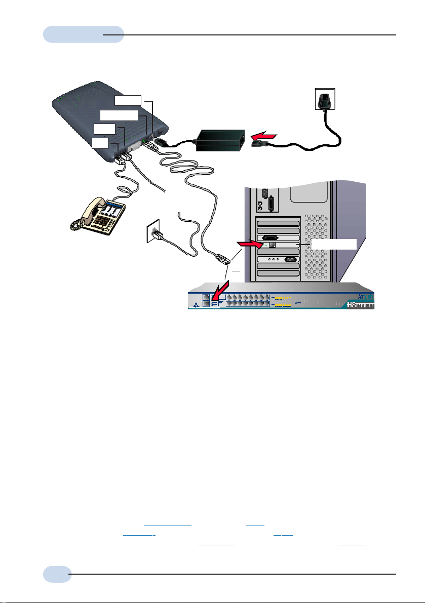
DSL905E
Telephone set
ETHERNET
LINE
TEL
3
DC IN
Telephone cable
(RJ-11)
Power adapter
Ethernet cable (RJ-45)
Mains Supply
4
5
Rear view of a PC
Telephone
Wall socket
(ADSL Line)
OR
A Hub/Switch
Ethernet Card
Figure 3-1. DSL905E connections
Carry out your connections as illustrated above.
For single PC connection, connect your Ethernet cable from your router to the Ethernet card
on a PC.
For multiple PCs connections, connect your Ethernet cable from your router to a Hub/
Switch. You may then connect your PCs (with Ethernet cards installed) to the Hub/Switch.
The number of PCs supported is dependent on the number of ports available in your Hub/
Switch.
Please proceed to the next section to verify the connections.
3 This optional connection provides easy access to your Telephone set while working near your
router.
4 Power off your Power Adaptor when the unit is not in use.
5 To connect direct to an Ethernet card, please use a Cross CAT-5 UTP Ethernet cable.
To connect to the MDI port of your Hub/Switch, please use Cross CAT-5 UTP Ethernet
cable. If not, you may connect to the MDIX port of your Hub/Switch using a Straight CAT-5
UTP Ethernet cable.
14
Page 15

User ManualUser Manual
User Manual
User ManualUser Manual
3.1 Verifying the Setup Connections
This is to verify the connections you have carried out on your router. Verifications are based
on the activity of the corresponding LED.
i) Power on the Mains Supply and the Power Switch of your router.
ADSL Link LED
You should see this LED blinks at the initial stage.
When the ADSL link is established, the LED will
remain lit up.
Ethernet Link LED
You should see this LED lights up.
Power LED
You should see this LED lights up.
If the LED(s) does not light up, check that:
a) the Mains Supply is powered on and the Power switch on DSL905E is at I
position.
b) the connections are carried out as described in Figure 3-1. DSL905E
Connections.
ii) If you have connected a Telephone set to your router, pick up the handset of the
Telephone. You should hear the normal dial-tone.
If you do not hear the normal dial-tone of a telephone, check that your telephone cable
connection is connected as illustrated in Figure 3-1. DSL905E Connections. If your
connection is correct, it may be due to a faulty phone cable that you are using.
Replace the phone cable.
Upon successful verifications, proceed to the next chapter to configure your Ethernet Card.
15
Page 16

Chapter4
Configuring Your
Ethernet Card
You need to configure the Ethernet Card on your PC in order to run DSL
1. The screen shots and screens information illustrated in this manual serve
only as a guide. The exact information you see on your system may
vary, depending on your system configurations. For any dissimilarities,
follow closely to the instructions as prompted on your PC screen.
2. All IP addresses and Subnet Mask indicated in this manual serve only
as examples for your better understanding. You are required to replace
these values with those given by your ISP / System Administrator.
6 DSL Router Commander is a user-friendly software that allows you to set, view and modify your
router configurations. For details, you may refer to the DSL Router Commander Software Manual.
Router Commander6 from your PC.
16
Page 17

User ManualUser Manual
User Manual
User ManualUser Manual
i) Ensure that your router is powered on.
ii) From your Windows desktop, right-click on the Network Neighborhood icon. Select
Properties.
iii) From the Configuration tab, select TCP/
IP-> 3Com EtherLink III ISA [3C509bTPO] in PnP mode
7
and click
Properties.
(If you do not see a TCP/IP networking protocol, reinstall your Ethernet card.)
iv) Select the IP Address tab.
Select the option 'Specify an IP
address'.
Enter the IP Address and
Subnet Mask as given by your
System Administrator. Click
OK to save the settings.
When prompted to restart, click Yes.
You may now proceed to the next chapter to run the DSLTEST for verifying the setups and
links.
7 This guide uses 3Com EtherLink III ISA Ethernet Card as an example. Select the Ethernet Card
that is listed in your system.
17
Page 18

Chapter5
Running DSLTEST
DSLTEST will check both the Ethernet Card connection and
If the first test failed, the next test will be skipped. Proceed to fix the
problem first before running DSLTEST again.
i) From your DSL905E Series CD-ROM, navigate to \Tools\DSLTEST. Double-click on
the file
ii) Click Test. The test will commence.
(DSLTEST).
configuration, as well as the ADSL line connection.
18
Page 19

User ManualUser Manual
User Manual
User ManualUser Manual
Result Description
PASS T he test is succe ssf ul.
FAIL
SKIP The test is not carried out as the previous test has failed.
You will be prompted on the error. Click OK, fix the error and
click Test again.
Ethernet Interface Test:
This will test whether your Ethernet Card is installed and configured properly. Error
messages will be prompted to highlight the area of the failure, if any. (You may refer
to the Troubleshooting Guide for details on the error messages.)
Modem Test:
This is to test the ADSL line connection. This test corresponds to the ADSL Link LED.
The lighting up of LED and passing of the Modem Test both show successful physical
ADSL link. (You may refer to the Troubleshooting Guide for details on the error
messages.)
19
Page 20

AppendixA
Frequently Asked
Questions
This section provides answers to the commonly asked questions
Why is Asymmetric Digital Subscriber Line (ADSL) called Asymmetric ?
It is called asymmetric because more bandwidth is reserved for receiving data
than for sending data. This is useful because many users of the Internet receive
much more data than they send.
What are the benefits of ADSL over analog modems ?
Besides the high-speed advantage, ADSL connection is always on. There is no
longer a need to log on and off, no more busy signals and no more waiting for the
connection to established - it is always there. On top of these, you can use the
phone even when the data connection is on. You do not need to switch between
surfing the Net and talking over the phone.
Will my router constantly connect near the maximum speed ?
At ADSL speeds, the limitations depend on the performance or load of the Internet
Service Provider that you are trying to reach, as well as the line condition specific
to your location.
on your router.
20
Page 21

User ManualUser Manual
User Manual
User ManualUser Manual
Can I use my router during thunderstorm ?
ADSL routers can be damaged by thunderstorms. Our product warranty does not
apply to damage caused by lightning. If your area is frequent in thunderstorms,
you are advised to use a surge protector. Certain surge protectors have been
reported to reduce download speed, so you are advised to test your speed before
and after installation to make sure that it adds no problems to your line.
Do I need to install additional telephone lines in order to use ADSL?
No, you do not need to do so. ADSL and standard voice telephones operate at a
different set of frequencies. The difference in frequencies allows both IP (Internet)
traffic and voice traffic to co-exist on a same physical phone line.
Will my old PC be fast enough for ADSL?
Yes. But if you start to use the ADSL line to view video-on-demand or other
memory and processor hungry functions, you may well decide that your PC is too
slow. However, there are still many interesting sites that can be seen and used by
slower PCs.
How can I send/receive fax as well as surfing the Internet at the same time ?
To send/receive fax, you may connect your fax machine to the TEL jack of your
router (same as the way you connect to the telephone set as illustrated in Chapter
3 - Connecting DSL905E).
Do I need to use Micro-Filter when using ADSL ?
Your router has a built-in Micro-Filter at the TEL jack. Thus no Micro-Filter is
required between your Telephone set and the router.
However, if you are sharing the ADSL line with other telephone line extensions,
you will need to have a Micro-Filter connected between the other telephone set
and the telephone wall socket connecting to it.
21
Page 22

User ManualUser Manual
User Manual
User ManualUser Manual
How do I verify the link between my Ethernet Card and router ?
To ensure that the communication link between your Ethernet Card and router has
been established, you may run the DSLTEST as described in Chapter 5 - Running
DSLTEST. A PASS at the Ethernet Interface Test will mean that the link between
your Ethernet Card and router has been established.
Alternatively, you may ping to your router to verify the link. Carry out the steps as
follow:
i) From your Windows taskbar, click Start > Run.
ii) In the text box, enter ping 192.168.1.1 -t and click OK.
iii) You should see strings of text similar to the listings shown below.
(The factory default IP Address for
DSL905E is set at 192.168.1.1.
Replace this address with the one
assigned by your System
Administrator, if necessary. This
IP address should be in the same
subnet as your router's IP
address.)
22
Close the window.
(If you see 'Request timed out' listing, it means that the link between your Ethernet
Card and your router has not been established. Refer to Appendix B -
Troubleshooting Guide, 'I get 'Request timed out' response when I ping to my
router'.)
Page 23

User ManualUser Manual
User Manual
User ManualUser Manual
I have already configured my router to my desired network configuration. But how
do I know if the link between my router and the Internet has been established ?
i) From your Windows taskbar, click Start > Run .
ii) Ping to any http address, example, www.aztech.com as illustrated below:
iii) If the link between your router and the Internet has been established, you will
see strings of text similar to the listings shown below.
Close the window.
23
Page 24

AppendixB
Troubleshooting Guide
This section provides a step-by-step solutions to problems that
you may encounter when setting up or using your router.
I am not getting any connection. My router's Power LED lights up, but the ADSL
Link LED keeps blinking instead of remaining lit up.
Power off your router and check the following:
i) Ensure that the Power adapter is tightly fitted into the DC IN of your router.
ii) Check that the Telephone cable (RJ-11) is connected to LINE jack on your
router and not to the TEL jack.
iii) Power on your router.
If the problem still persist, please check with your Internet Service Provider.
24
I am getting poor ADSL speed performance from my router.
i) Ensure that the ADSL line is at least 10cm away from the Power adapter.
(see the following page for illustration.)
ii) Place your router away from devices or appliances such as monitors, exposed
computer systems (with chassis covers removed) or another router which exhibit
magnetic fields that may cause interferences to your router line.
iii) Ensure that Micro-Filters are used for phone sockets that are sharing the same
ADSL line.
Page 25

User ManualUser Manual
User Manual
User ManualUser Manual
If your router speed or performance is still unsatisfactory, please contact your
Internet Service Provider.
The Mains Supply
Power adapter
Rear view of
DSL905E
be greater than 10cm
Telephone cable
(RJ-11) - ADSL Line
Telephone wall
socket
Figure B-1. Distance between DSL905E and Power adapter
I get 'Request timed out' response when I ping to my router.
Check that you have entered the correct IP Address for your Ethernet Card as
specified by your System Administrator (see Chapter 4 - Setting Up Your Ethernet
Card). It should be in the same subnet as your router's IP address.
Restart your system for the IP Address to take effect and try to ping again.
25
Page 26

User ManualUser Manual
User Manual
User ManualUser Manual
I am prompted with the error message 'Network adapter not found' when running
the DSLTEST.
Your Network Card could be faulty. Click OK. Replace your Network Card and try
running the DSLTEST again.
I am prompted with the error message 'The IP setting is wrong. Please refer to
user manual on Configuring Your Ethernet Card' when running the DSLTEST.
Click OK. Check that you have entered the correct IP Address for your Ethernet
Card as specified by your System Administrator (see Chapter 4 - Setting Up Your
Ethernet Card). It should be in the same subnet as your router.
Restart your system for the IP Address to take effect. Try running the DSLTEST
again.
26
I am prompted with the following error message when running the DSLTEST.
Follow the error message instructions. Check that you have powered on your
router. Ensure that you have used the correct Ethernet cable for the connection
between your router and Ethernet Card (see Chapter 3 - Connecting DSL905E).
Click OK and try running the DSLTEST again.
Page 27

User ManualUser Manual
User Manual
User ManualUser Manual
I am prompted with the error message 'Please plug in the line and try it again'
when running the DSLTEST.
Click OK. Make sure that you have connected the telephone cable (RJ-11) from
the LINE jack, and not the TEL jack on your router to your telephone wall socket.
Try running the DSLTEST again. If it still fails, it could be that you are having a
faulty phone cable. Replace the phone cable and try again.
I am prompted with 'Bad configuration file, please review' error message after
entering
config confirm
command. (You may experience this when you are
configuring your DHCP. See the section on Configuring DHCP Server on your
Technical Manual.)
The error message is prompted when system detected some errors in commands
that you have entered. To review the commands, type
config
. An example of the
listing is as shown.
Go through the commands to locate the error(s).
To correct the error(s), you may type either
command line or
config flush
to remove ALL entered command lines. Re-enter the
config delete
correct commands.
Complete the configuration settings with
reset
.
to remove the last entered
home, config save
and
dhcpserver
27
Page 28

User ManualUser Manual
User Manual
User ManualUser Manual
The following error message was prompted when I tried to log in to DSL Router
Commander.
This happens when system is not able to detect a link between your Ethernet card
and your router. Go through the listed possible errors at the above prompt before
logging in again. (For point 3, you may refer to Chapter 4 - Configuring Your
Ethernet Card to verify the IP address of your Ethernet Card.)
28
Page 29

AppendixC
Technical Specifications
This section contains the specifications for DSL905E.
C.1 Main Features
C.1.1 ADSL/ATM Support
Controller-based External ADSL Modem
ANSI T1.413 issue 2, ITU-T G.992.1 (G.dmt) and G.992.2 (G.lite) compliant
Using Discrete Multi-Tone (DMT) line encoding scheme
Full Rate transmission at up to 8 Mbps downstream and 1Mbps upstream
G.lite transmission at up to 1.5 Mbps downstream and 512 Kbps upstream
Rate Adaptive modem at 32 Kbps steps
ATM Layer with Traffic shaping (UBR/CBR/VBR-nrt/VBR-rt)
AAL ATM Attributes - AAL5
VPI Range (0-4095) and VCI range (1-65535)
Multiple PVC up to 8 support
UNI 3.0, 3.1 and UNI 4.0 ATM Signaling (support for SVCS)
Spectral compatibility with POTS
F4/F5 OAM Send and Receive/Loopback supported
Trellis Coding support
Built in POTS splitter
29
Page 30

User ManualUser Manual
User Manual
User ManualUser Manual
C.1.2 Encapsulation Support
RFC1483 Bridged and Routed for both LLC/VC Mux
RFC1577 Classical IP Supported
RFC2364 PPPoA protocol stack support
RFC2516 PPPoE Relay support
RFC2516 PPPoE Client support
Transparent Bridge Support
Spanning Tree Support
[DSL905E(R2) only]
C.1.3 Network Support
Static IP, RIP1 and RIP2 routing support
TCP/UDP Application Support
Network Address Translation (NAT)
Port Address Translation (PAT)
NAT Application Level Gateway for FTP and Gaming Applications
DHCP Server
DHCP Client and Relay Agent
DNS Relay Agent
PPTP Access Concentrator Support
L2TP Access Concentrator Support [DSL905E(R2) only]
[DSL905E(R2) only]
[DSL905E(R2) only]
C.1.4 Management Support
TFTP Software update support
Local management via Serial (RS-232) Console
Remote management through Telnet
DSL Router Commander GUI for configuration assistance
SNMP support for management functionality
Flash ROM upgradable for future feature enhancement
Web based Management (Firmware Upgrade)
[DSL905E(R2) only]
C.1.5 Security Support
PAP/CHAP for Password Authentication Support
NAT for basic Firewall support
MAC address Filtering
Packet Filtering support (Firmware Upgrade)
30
[DSL905E(R2) only]
Page 31

User ManualUser Manual
User Manual
User ManualUser Manual
C.2 Platform Support
OS Independent (supports any platform with an ethernet card installed)
C.3 External Connectors
1 x RJ-11 Telephone socket for ADSL line
1 x RJ-11 Telephone socket for Telephone Handset
1 x RJ-45 for 10Base-T Ethernet
1 x DC Power Jack
1 x On/Off Power Switch
9-pin Serial Port for local management
C.4 Built-In Pots Splitter
Used for separation of the ADSL and Telephone signals, preventing mutual interference.
Micro-filter is a passive device. In the event of power failure on any active components,
there will be no disruption to the telephone service.
• Line Side differential input blocking impedance
- At 20 kHz >2k
- At 30 kHz >3k
- From 5 MHz to 10 MHz >4k
- From 10 MHz to 400MHz >2k
- 1 kHz insertion loss between 600 Ohm resistive at < 0.7
- 1 kHz/2.8kHz slope between 600 Ohm resistive at < 0.8
- DC resistance in Ohms
- Tip to Tip, and Ring to Ring < 50
- Tip to Ring >10M
- Longitudinal Balance per IEEE Method
- From 200 1 kHz > 58dB
- From 1 kHz 3 kHz > 53dB
- Envelope Delay 300 Hz 2800 Hz is < 100 ms
31
Page 32

User ManualUser Manual
User Manual
User ManualUser Manual
C.5 LED Indicators
- 1 x Power LED
- 1 x Ethernet Link Status LED
- 1 x Ethernet Activity LED
- 1 x ADSL Receive LED
- 1 x ADSL Transmit LED
- 1 x ADSL Link Status LED
C.6 Environmental
C.6.1 Temperature
Operating : 10o to 45 o Celsius (50 o to 113 o Fahrenheit)
Non-Operating : -25
C.6.2 Humidity
Operating : 30% to 80% Relative Humidity (Non-Condensing)
Non-Operating : 10% to 95% Relative Humidity (Non-Condensing)
o
to 70 o Celsius (-13 o to 158 o Fahrenheit)
C.7 System Requirements
Pentium MMX 233MHz (or above) with Ethernet card
The product specifications herein are subject to change without prior
notification.
32
P/N: 040-512452-101 (Released date: May 2001)
 Loading...