

Page 1

DSL700P
Version 1.1
ADSL MODEM CARD
Users Manual
(Configured for SingTel Magix Service)
Page 2

Page 3
Contents
○○○○○○○○○○○○○○○○○○○○
Introduction .....................................................................
Before You Begin ..............................................................
2.1 Minimum System Requirements ......................................................
2.2 Safety Precaution............................................................................
2.3 Installation Notes............................................................................
Setting Up the Modem Card ............................................
3.1 Installing the Modem Card..............................................................
3.2 Connecting the Modem Card ..........................................................
Installing the Modem Driver .............................................
Using the Internet ............................................................
Uninstalling the Modem Driver .........................................
ADSL MAPI Icon .............................................................
5
6
7
8
8
9
9
12
13
19
23
25
A-1 MAPI LEDs .....................................................................................
A-2 MAPI Menu ....................................................................................
Technical Specifications....................................................
Frequently Asked Questions .............................................
Troubleshooting Guide .....................................................
Technical Support ............................................................
25
26
29
33
37
41
Page 4

ADSL Modem User’s Manual
This page is intentionally left blank.
○○○○○○○○○○○○○○○○○○○○○○○○○○○○○○○○○○○○○○○○○
4
Page 5

1. Introduction
○○○○○○○○○○○○○○○○○○○○
Introduction
Congratulations on your purchase of DSL700P ADSL Modem card!
ADSL, which stands for Asymmetric Digital Subscriber Line, is the latest
communication technology that offers faster and uninterrupted Internet access.
The DSL700P is a PCI based Controller-less ADSL modem. It is capable of
data rate in both Full-Rate and G.Lite, with Full Rate transmission up to 8
Mbps downstream, 640 Kbps upstream and G.Lite transmission up to
1.5 Mbps downstream, 512 Kbps upstream.
With ADSL modem, you do not require a new phone line. Neither do you
need to switch your existing phone line between phone communication and
Internet surfing. The ADSL modem makes use of your existing phone line for
Internet surfing and at the same time, allows you to talk on the phone! As your
phone line is dedicated to your home, your connection to the Internet will also
be highly secured and reliable!
DSL700P definitely meets more than comfortably, the demands of todays
bandwidth intensive applications!
○○○○○○○○○○○○○○○○○○○○○○○○○○○○○○○○○○○○○○○○○
5
Page 6

ADSL Modem User’s Manual
This page is intentionally left blank.
○○○○○○○○○○○○○○○○○○○○○○○○○○○○○○○○○○○○○○○○○
6
Page 7
○○○○○○○○○○○○○○○○○○○○
Before You Begin
This chapter contains information that you need to know before
installing your modem card. Please go through them before
proceeding with the installation.
2.1 Minimum System Requirements
2.1.1 Hardware
2. Before You Begin
• IBM PC-based computer with Pentium
®
166 processor
• A CD-ROM drive
• A free PCI Bus slot
• 32MB RAM
• 30MB free hard disk space (system files and modem drivers only)
2.1.2 Software - Operating System
Windows® 98 Second Edition
○○○○○○○○○○○○○○○○○○○○○○○○○○○○○○○○○○○○○○○○○
7
Page 8

2. Before You Begin
2.2 Safety Precaution
• Do not remove your card from its protective bag until you are ready to
install it.
• Always try to hold your card by its edges. Avoid touching any electronic
components on your card.
• Static electricity can cause permanent damage to your card. To prevent
such a damage, you must ground yourself during the installation:
» Use a grounding strap - a coiled wire with a clip at one end and an
elastic strap at the other. Wear the strap around your wrist and
attach the clip to any non-painted metal surface of your computer
chassis.
» If you do not have a grounding strap, touch any non-painted surface
of your computer chassis before you begin installation, and again
every minute or so until the installation is completed.
2.3 Installation Notes
• The graphics and screen illustrations shown in this manual may differ from
what you see in your system, but the steps still apply.
• A Philips screwdriver is required.
• The documentation for your computer should come in handy during the
installation. Have it ready by your side.
• If you have an existing non Plug-and-Play modem installed in your computer,
you must first uninstall its modem driver before you remove the card. Refer
to the documentation of your existing modem for details.
If your existing modem is Plug-and-Play, you may proceed to install your
new modem.
○○○○○○○○○○○○○○○○○○○○○○○○○○○○○○○○○○○○○○○○○
8
Page 9
○○○○○○○○○○○○○○○○○○○
This chapter contains information on how to install and connect the
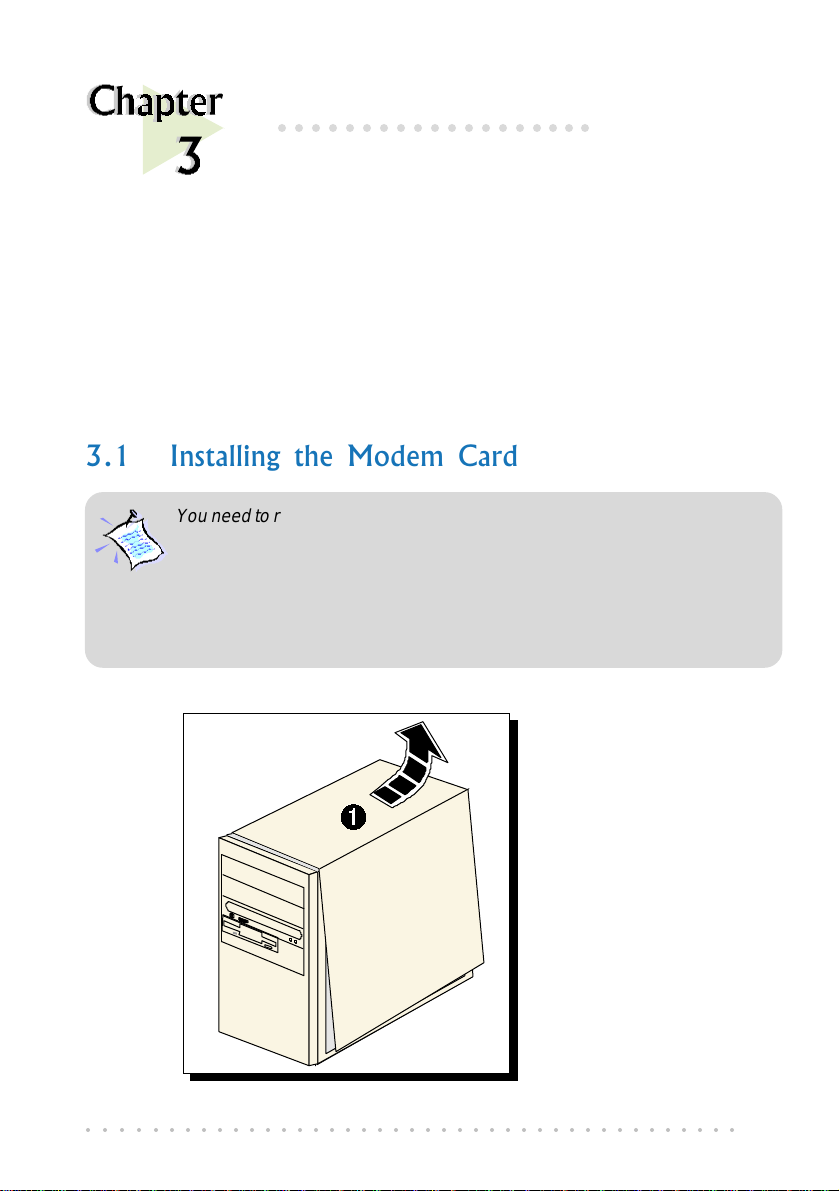
3.1 Installing the Modem Card
You need to remove any existing modem installed in your computer . If your
modem is non Plug-and-Play, you need to uninstall its modem driver before
you remove it. Check your existing modem documentation for details on
this.
Power off your computer and any connected devices before installing
your modem!
3. Setting Up the Modem Card
Setting Up the
Modem Card
modem card.
¶ Remove the cover
of your computer.
○○○○○○○○○○○○○○○○○○○○○○○○○○○○○○○○○○○○○○○○○
9
Page 10
3. Setting Up the Modem Card
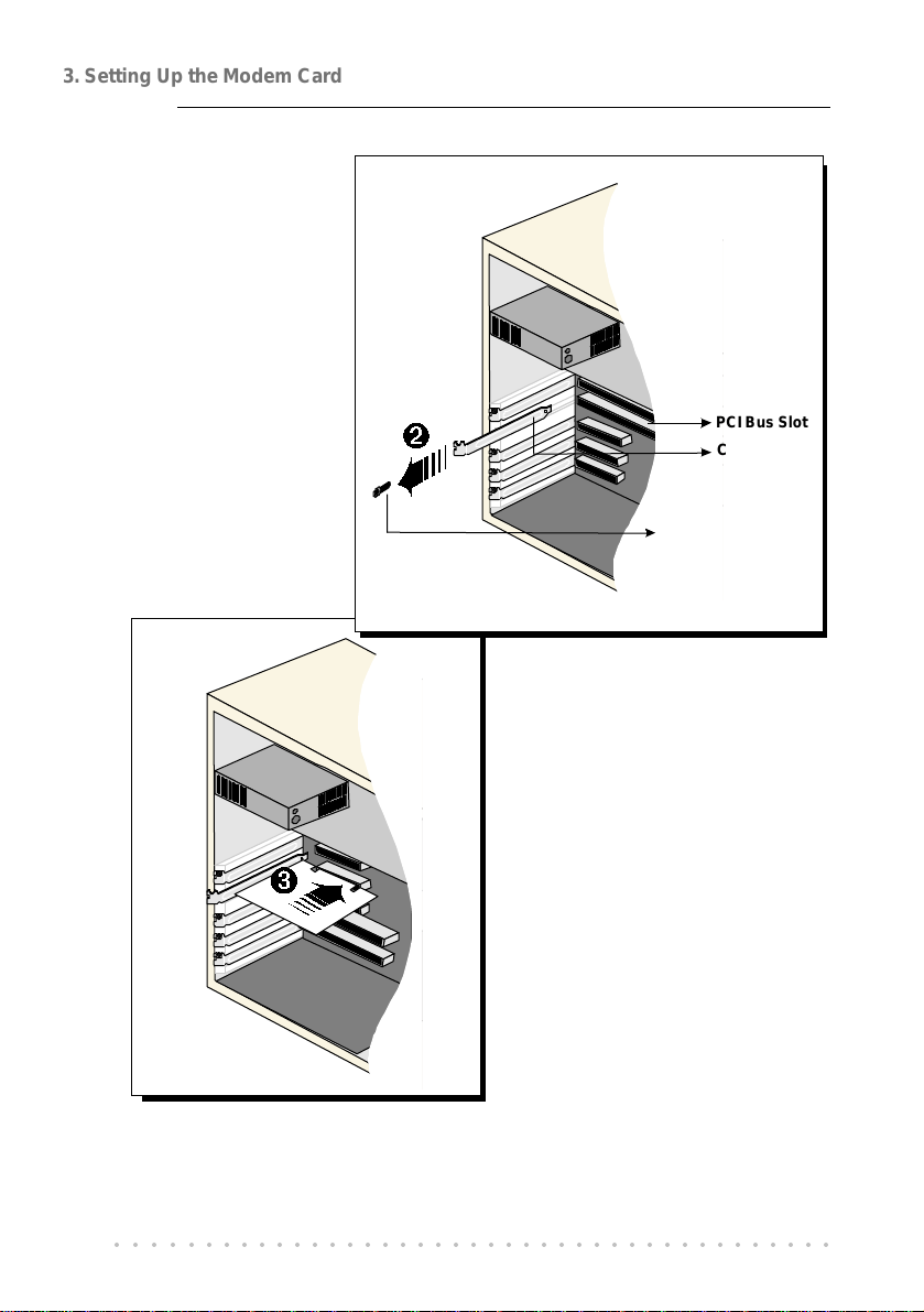
Ë Locate any
available PCI Bus
Slot and remove
its cover plate.
Keep the mounting
screw to secure
your card later.
PCI Bus Slot
Cover Plate
Mounting Screw
Ì Align your card with the
selected PCI Bus slot and
firmly push it into the slot.
If the card does not slide
in, do not force it. Make
sure that the card is
aligned properly and try
again.
○○○○○○○○○○○○○○○○○○○○○○○○○○○○○○○○○○○○○○○○○
10
Page 11
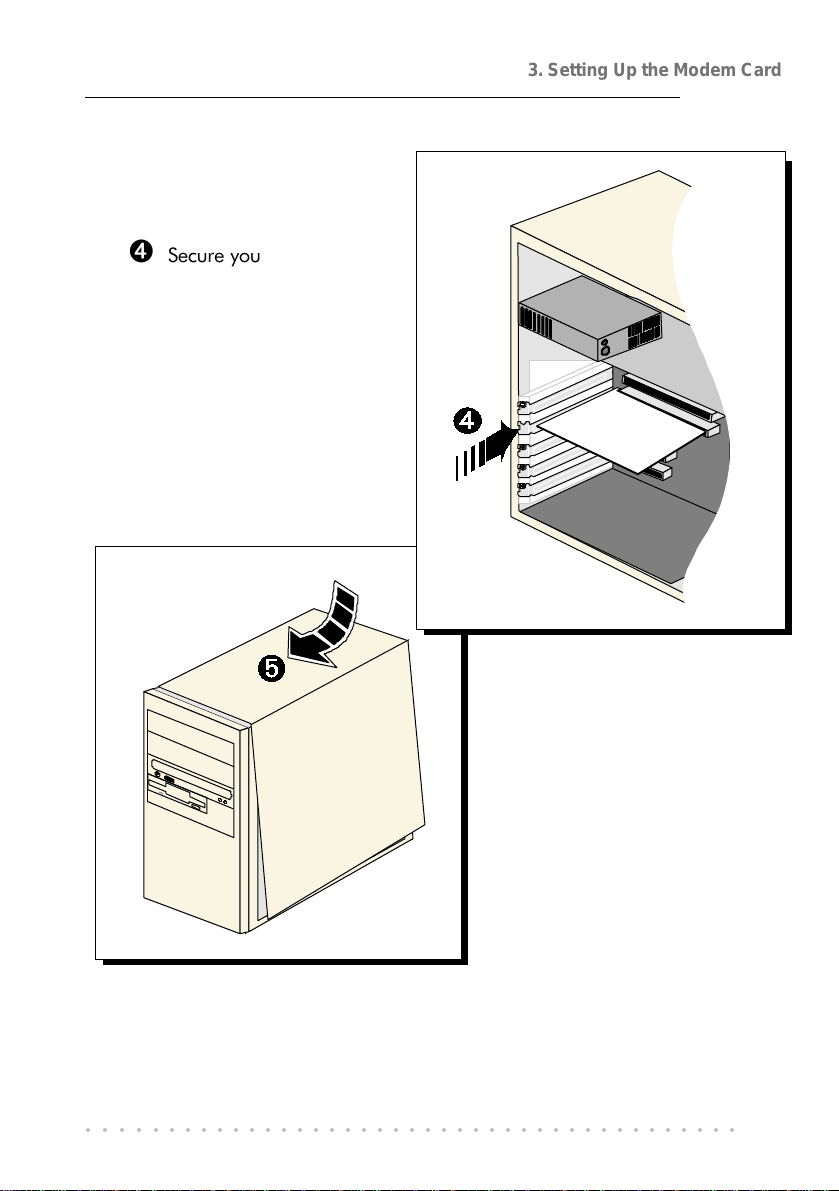
Í Secure your card to the
computer chassis with
the mounting screw.
3. Setting Up the Modem Card
Î Replace the cover of
your computer.
This completes the ADSL modem card installation. Please proceed to the
following section on the card connection for ADSL line.
○○○○○○○○○○○○○○○○○○○○○○○○○○○○○○○○○○○○○○○○○
11
Page 12
3. Setting Up the Modem Card
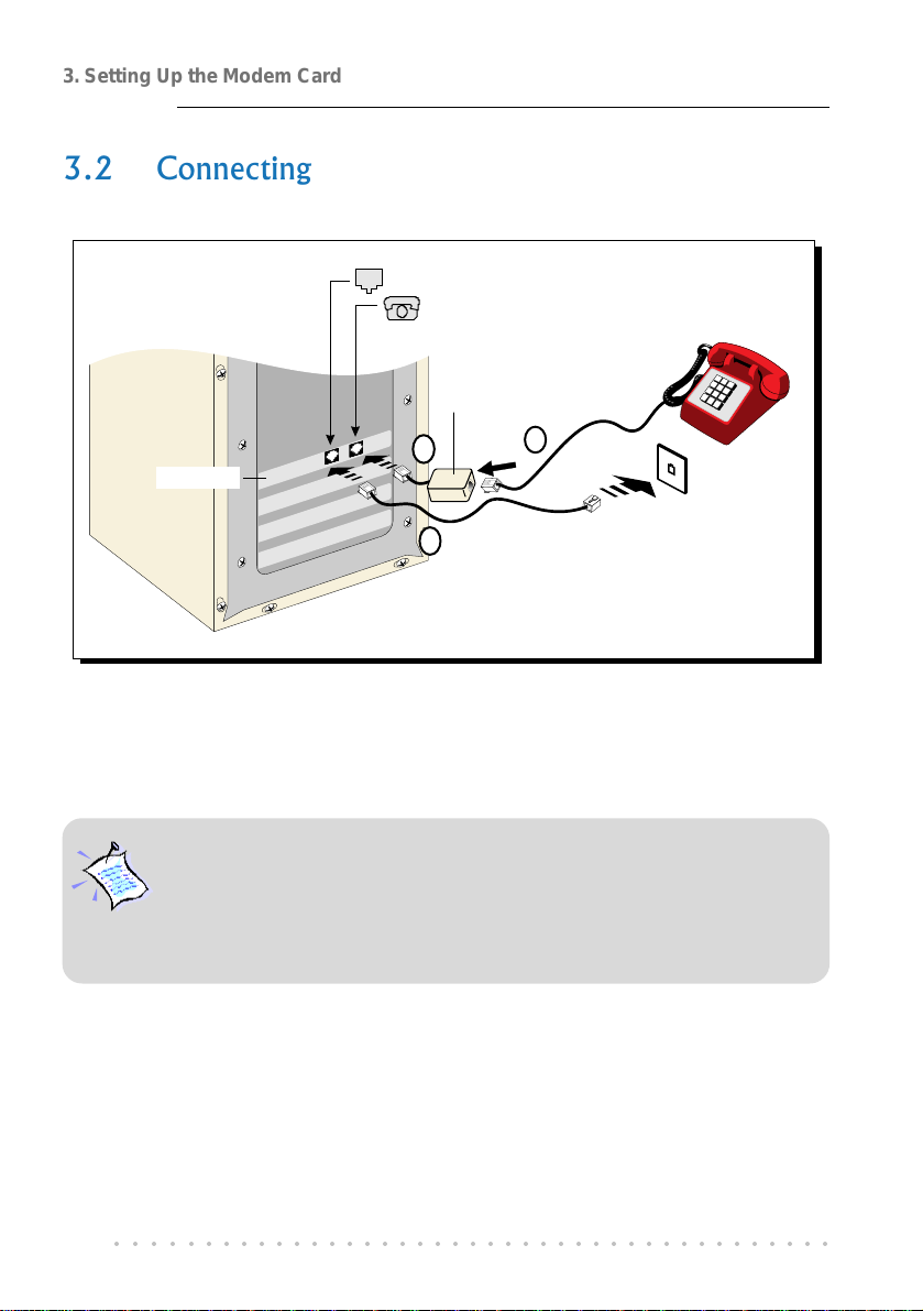
3.2 Connecting the Modem Card
to Telephone Wall Socket
from Telephone set
†Micro-Filter
Telephone set
Ë
Telephone
Wall Socket
Telephone
extension cord
The use of micro-filter
optimizes the G.Lite operation.
DSL700P
Ê
Ì
This completes the ADSL modem card connection. Please proceed to the next
chapter to install the driver for your modem.
The connection to the T elephone set is optional. The Phone jack provides
convenience to users who need to use the phone when accessing the
computer.
The Micro-Filter is not required if you are not connecting to a Telephone
set.
○○○○○○○○○○○○○○○○○○○○○○○○○○○○○○○○○○○○○○○○○
12
Page 13
4. Installing the Modem Driver
○○○○○○○○○○○○○○○○○○○
Installing the
Modem Driver
This chapter contains information on how to install the driver for
ADSL modem card in Windows
1. The screens illustrations in this chapter assume that your CD-ROM
Drive is ‘D’. Please change the letter according to your own CD-
ROM drive.
2. System may prompt for your Windows 98 Second Edition
Installation CD during the driver installation. Have it ready by your
side.
®
98 Second Edition.
○○○○○○○○○○○○○○○○○○○○○○○○○○○○○○○○○○○○○○○○○
13
Page 14
4. Installing the Modem Driver
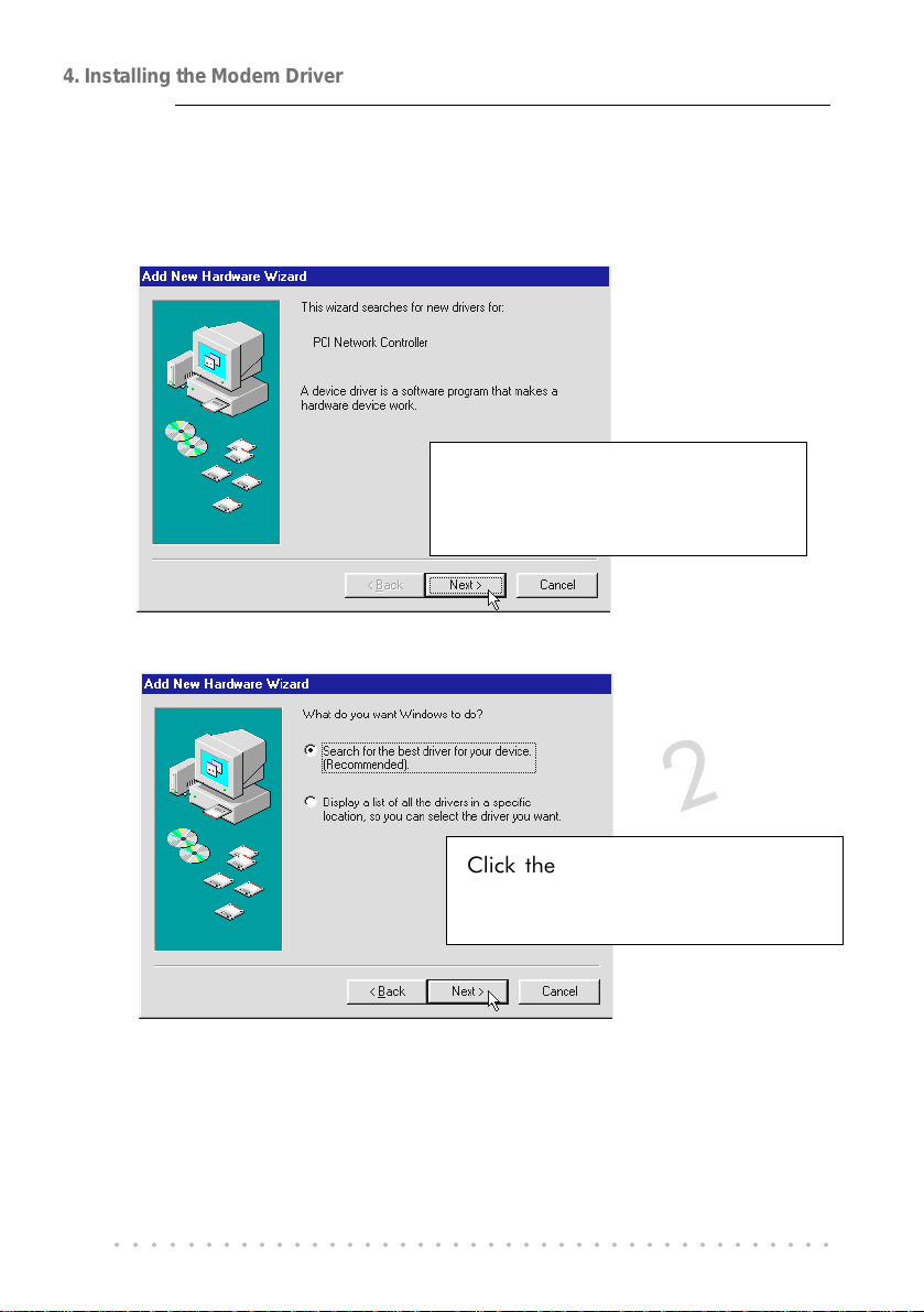
Power on your computer to start Windows. It will detect the newly-installed
ADSL modem card and prompt for its driver.
1
Place the DSL700P Installation
CD into your CD-ROM Drive and
click Next.
2
Click the option "Search for the
best driver for your device.
(Recommended)." and click Next.
○○○○○○○○○○○○○○○○○○○○○○○○○○○○○○○○○○○○○○○○○
14
Page 15

3
Select Specify a location and
click Browse... .
Navigate to the directory
\Win98SE on your CD-ROM and
click OK.
Click Next.
4. Installing the Modem Driver
4
Click Next again to proceed
installation with the specified driver.
Allow some time for your system to
install the driver.
○○○○○○○○○○○○○○○○○○○○○○○○○○○○○○○○○○○○○○○○○
15
Page 16

4. Installing the Modem Driver
System may prompt for your Windows 98 Second Edition Installation
CD.
5
6
Replace the DSL700P
Installation CD in your CD-
ROM drive with your Windows
Installation CD and click OK.
Upon copying files
complete, click Finish.
7
Click Yes to restart
your system.
This completes the driver installation for your ADSL modem card in Windows
98 Second Edition.
○○○○○○○○○○○○○○○○○○○○○○○○○○○○○○○○○○○○○○○○○
16
®
Page 17

4. Installing the Modem Driver
Allow some time for your system to restart. Upon system rebooted, please
proceed with the following step to verify if your card has been installed properly.
8
i) From your Windows taskbar, click
Start > Settings > Control Panel.
ii) Double-click System icon.
iii) From the Device Manager tab,
double-click Network adapters.
You should see DSL700P ADSL
Network Modem listed.
(If the component is not listed, reinstall your driver.)
○○○○○○○○○○○○○○○○○○○○○○○○○○○○○○○○○○○○○○○○○
17
Page 18

4. Installing the Modem Driver
This page is intentionally left blank.
○○○○○○○○○○○○○○○○○○○○○○○○○○○○○○○○○○○○○○○○○
18
Page 19

1
2
5. Using the Internet
○○○○○○○○○○○○○○○○○○○
Using the Internet
This chapter contains information on creating a dial-up icon for the
Magix Internet Connection.
For connection to Magix Internet, you need to create a dial-up icon.
From your Windows taskbar, click Start > Programs > Accessories
> Communications > Dial-Up Networking.
Click Next.
○○○○○○○○○○○○○○○○○○○○○○○○○○○○○○○○○○○○○○○○○
19
Page 20

5. Using the Internet
3
4
Enter Magix for the
computer name and select
DSL700P device. Click Next.
Enter Magix as the Host
name / IP address and
click Next.
5
Click Finish to complete
the dial-up icon settings.
○○○○○○○○○○○○○○○○○○○○○○○○○○○○○○○○○○○○○○○○○
20
Page 21

6
7
5. Using the Internet
A dial-up icon, will be generated on your Windows desktop.
Double-click on the icon. Enter your username and password. Click
Connect to establish a connection to Magix.
Upon successful username and password verifications, you will be
able to access the Internet.
(For details, you may refer to the Magix Service Manual that comes
with your package.)
○○○○○○○○○○○○○○○○○○○○○○○○○○○○○○○○○○○○○○○○○
21
Page 22

5. Using the Internet
This page is intentionally left blank.
○○○○○○○○○○○○○○○○○○○○○○○○○○○○○○○○○○○○○○○○○
22
Page 23

6. Uninstalling the Modem Driver
○○○○○○○○○○○○○○○○○○○○
Uninstalling the
Modem Driver
This chapter contains information on how to uninstall the modem
Make sure that you have exited the MAPI Icon before proceeding with the
uninstallation.
(From your Windows taskbar, right-click on . Select Exit.)
From your Windows taskbar, click Start > Settings > Control
1
Panel. Double-click icon.
From the Install/
Uninstall tab, select
2
Uninstallation and click
Add/Remove... .
Follow the on-line instructions to
complete the uninstallation process.
Restart the system when prompted.
DSL700P
driver in Windows
®
98 Second Edition.
○○○○○○○○○○○○○○○○○○○○○○○○○○○○○○○○○○○○○○○○○
23
Page 24

6. Uninstalling the Modem Driver
This page is intentionally left blank.
○○○○○○○○○○○○○○○○○○○○○○○○○○○○○○○○○○○○○○○○○
24
Page 25

A. ADSL MAPI Icon
○○○○○○○○○○○○○○○○○○○○
ADSL MAPI Icon
This chapter explains the functions on the MAPI Icon.
The MAPI Icon allows you to monitor your ADSL connection, ATM/ADSL
states, configure the PVC values and run a few diagnostics tests.
Upon successful driver installation, the MAPI icon , will be displayed at the
corner of your Windows taskbar.
A-1 MAPI LEDs
The left LED indicates information being transmitted and the right LED
indicates information being received. The following table summaries the
LED activities.
LED Description
Red, Red No ADSL connection
Black, Yellow is flashing
or
Yellow, Black is flashing
Black, Black ADSL Connection es tablished - no data traffic
Green, Green
Green, Black
Black, Green
Ø Modem is disconnected, or a problem exists
○○○○○○○○○○○○○○○○○○○○○○○○○○○○○○○○○○○○○○○○○
Establishing ADSL connection
ADSL Connection es tablished - modem is
transmitting and receiving data
ADSL Connection es tablished - modem is
transmitting data
ADSL Connection es tablished - modem is
receiving data
25
Page 26

A. ADSL MAPI Icon
A-2 MAPI Menu
Right-click the MAPI Icon . The MAPI Menu will be displayed.
A-2-1 Connect/Disconnect
This option allows you to connect or disconnect from the central office
equipment.
For advanced users (A-2-2 to A-2-5)
A-2-2 Diagnostic
This option allows you to view the product information and to perform
hardware test on the ADSL card (e.g. ADSL Bridge test and Registers test).
Product Infor lists the versions of the MAPI Icon and the protocol driver installed.
The DLL version describes the software being used by both the drivers and MAPI
Icon.
This information is useful
whenever making a
technical support call.
Run Diagnostics performs a brief
hardware check and display the
hardware status.
Close all Dial-up sessions before
running the diagnostic test.
○○○○○○○○○○○○○○○○○○○○○○○○○○○○○○○○○○○○○○○○○
26
Page 27
A. ADSL MAPI Icon
A-2-3 ADSL Status
This dialog box allows you to monitor the ADSL connection as well as the
transmit and receive line rates.
ADSL State displays the current status of the modem.
Protocol displays which ADSL standard is being used.
Transmit/Receive Rate shows the line rate for both the upstream and
downstream.
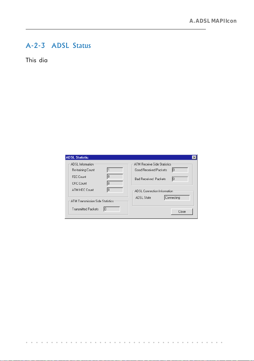
A-2-4 ATM/ADSL Statistic
This dialog box keeps tabs on errors that might affect overall system
performance. The counts are reset whenever the PC system is restarted.
Re-training Count tracks the number of ADSL connections performed.
Due to unexpected line condition changes, the driver can retrain the
connection causing the Re-training Count to increase.
ADSL implements Reed Solomon (RS) error checking:
FEC Count tracks the forward error correction count.
CRC Count tracks the accuracy of correcting data errors over each 17msec.
ATM HEC Count (header error check) errors are recorded as an indication
of ATM packet accuracy.
As a measure of packet transfer performance, the Packet Errors are counted
and tracked against the total number of Packets Received. An error rate
of less than 0.1% is reasonable under clean ADSL line conditions.
○○○○○○○○○○○○○○○○○○○○○○○○○○○○○○○○○○○○○○○○○
27
Page 28

A. ADSL MAPI Icon
If you have received Bad Received Packets and are concerned about your
service, multiply the Bad Received Packets count by 1000 and compare the
result with the total Packets Received count. If the number is smaller than
the total Packets Received count, then the board is operating normally.
• ATM Transmission Side Statistics displays the number of packets
transmitted.
• ATM Receive Side Statistics displays the number of good and bad packets
received.
A-2-5 Configuration
This option allows you to check or change the ADSL network modem PVC
values.
○○○○○○○○○○○○○○○○○○○○○○○○○○○○○○○○○○○○○○○○○
28
Page 29

○○○○○○○○○○○○○○○○○○○
Technical Specifications
This chapter contains the technical specifications of your card.
The information may be more useful for technically inclined
B-1 Drivers Support
B. Technical Specifications
users.
• Windows
®
98 Second Edition
B-2 Features
• 32-bit Controllerless ADSL PCI Modem
• UTOPIA Specifications Level I and Level II compliant
• ANSI T1.413 issue 2, ITU-T G.992.1 (G.dmt) and G.992.2 (G.lite) compliant
• Using Discrete Multi-Tone (DMT) line encoding scheme
• Full rate transmission at up to 8 Mbps downstream and 640 Kbps upstream
• G.lite transmission at up to 1.5 Mbps downstream and 512 Kbps upstream
• Rate Adaptive modem at 32 Kbps steps
• Up to 18,000 ft loop reach
• PCI 2.1 Power Management specification compliant
• Software upgradable for future feature enhancement
• Full RFC1483/RFC1577/ RFC2364 protocol stack support
• Spectral compatibility with POTs
○○○○○○○○○○○○○○○○○○○○○○○○○○○○○○○○○○○○○○○○○
29
Page 30

B. Technical Specifications
B-3 ADSL Chipset
Using ITEX Apollo2 Chipset :
• I90188 ADSL PCI/UTOPIA Interface
• I90135 ADSL DMT Modem and ATM Framer
• I90134 ADSL Analog Front End
• NDIS 5.0 miniport driver
B-3-1 I90188 ADSL PCI/Utopia Interface
- PCI 32-bit Bus Master Interface compliant to PCI Specification v2.2
- UTOPIA Level I v1.0 and Level II v2.01 support for D0 and D3 hot
- I90135 Configuration Register Interface
- ANSI T1.413 issue 2, ITU-T G.992.1 (G.dmt) and G.992.2 (G.lite)
compliant
- AC97 Digital Controller compliant to AC97 Specification 2.1
- +3.3-volt & +5-volt supplies, 1.60-pin PQFP
B-3-2 I90135 ADSL DMT Modem & ATM Framer
- ANSI T1.413 Issue 2 standard DMT modem with embedded ATM
Framer
- Standard Utopia Level I and Level II ATM Interfaces
- DMT Modulation up to maximum of 256 tones (14 bits)
- ADSL/ATM cell-specific Framing and Deframing
- Generic ATM TC Layer functions
- ATM Specific TC Layer functions
- Rotor and Frequency Domain Gain Correction and Equalization
- Performs DMT Modulation, Demodulation, Reed-Solomon Encoding,
Bit Interleaving, and 4D Trellis Coding
- 3.3-volt, 144-pin PQFP
B-3-3 I90134 ADSL Analog Front-End
- Integrated Analog Front End (AFE) for ADSL
- High sampling rate at 8.832 MHz for both ADC and DACs
○○○○○○○○○○○○○○○○○○○○○○○○○○○○○○○○○○○○○○○○○
30
Page 31

B. Technical Specifications
- Two (2) 12-bit DACs, One 13-bit ADC
- Differential Analog Input/Output
- Accurate continuous-time low pass filters for channel filtering
- 3.3-volt, 64-pin LQFP
B-4 ADSL Software Support
- ATM Layer with Traffic shaping
- AAL ATM Attributes - AAL5 & SAR
- RFC-2364 PPP over ATM PVCs
- RFC-1483 Routed IP over ATM PVCs
- RFC-1577 Classical IP over ATM PVCs
- UNI 3.0, 3.1 and UNI 4.0 ATM Signalling
B-5 Interfaces
B-5-1 External connectors
- 2 x RJ11 Telephone socket for telephone line & handset
The specifications herein are subject to change without prior
notification.
○○○○○○○○○○○○○○○○○○○○○○○○○○○○○○○○○○○○○○○○○
31
Page 32

B. Technical Specifications
This page is intentionally left blank.
○○○○○○○○○○○○○○○○○○○○○○○○○○○○○○○○○○○○○○○○○
32
Page 33

C. Frequently Asked Questions
○○○○○○○○○○○○○○○○○○○○
Frequently Asked Questions
This chapter provides the answers to some of the commonly
asked questions on your modem.
What is ADSL ?
ADSL, Asymmetric Digital Subscriber Line is a broadband
communication technology designed for use on regular phone lines. It
has the ability to move data over the phone lines at speeds up to 140
times faster than the analog modem available today.
Why is it called Asymmetric ?
It is called asymmetric because more bandwidth is reserved for receiving
data than for sending data. This is useful because many users of the
Internet receive much more data than they send.
What are the benefits of ADSL over analog modems ?
Besides the high-speed advantage, ADSL connection is always on.
There is no longer a need to log on and off, no more busy signals and
no more waiting for the connection to established - it is always there.
On top of these, you can use the phone even when the data connection
is on. You do not need to switch between surfing the Net and talking
over the phone.
○○○○○○○○○○○○○○○○○○○○○○○○○○○○○○○○○○○○○○○○○
33
Page 34

C. Frequently Asked Questions
Will my modem constantly connect near the maximum speed ?
At ADSL speeds, the limitations are much more of the performance of
the Internet server you are trying to reach and the amount of traffic on
the Internet.
Can I connect to the Magix Internet Services everywhere I
go?
No, you cannot. You can connect to this service, only via ADSL phone
line enabled for the Magix Internet Services.
Can I run both dial-up modem and ADSL modem?
Yes, but it is not recommended. You may experience slowness during
surfing as well as incurring additional cost of maintaining two active
connections.
Do I need to use Micro-Filter when using ADSL?
Yes, if you are sharing your DSL line with your telephone. The Micro-
Filter would eliminate noise on the telephone line to ensure the best
possible networked phone performance. If the DSL uses a different
line and not sharing with your telephone, then a Micro-Filter wouldnt
be necessary.
How do I most efficiently connect Micro-Filters to my telephone
network ?
Please refer to the diagram on the following page.
Generally, you should abide to the following rules:
1. The port of the Micro-Filter must be connected to your normal phone
device (exclude ADSL modem) with its tail end to the wall socket.
The reverse will not work.
○○○○○○○○○○○○○○○○○○○○○○○○○○○○○○○○○○○○○○○○○
34
Page 35

C. Frequently Asked Questions
2. The Micro-Filter should be connected to the top-most branch of the
wiring tree that is not connected to the ADSL modem. That implies
that the segments of RJ11 cable (see dotted line in the diagram)
from the wall socket to the ADSL modem must not be microfiltered.
3. Restrict the number of Micro-Filters to a maximum of 4.
Telephone
Telephone Telephone
Analog Modem
Analog Modem
○○○○○○○○○○○○○○○○○○○○○○○○○○○○○○○○○○○○○○○○○
Telephone
Fax
Telephone
Telephone
Telephone Telephone
ADSL modem
Fax
RJ11 cable segment
RJ11 cable segment
with microfilter
Wall socket
Wall socket with
RJ11 coupler
RJ11 coupler
35
Page 36

C. Frequently Asked Questions
This page is intentionally left blank.
○○○○○○○○○○○○○○○○○○○○○○○○○○○○○○○○○○○○○○○○○
36
Page 37

D. Troubleshooting Guide
○○○○○○○○○○○○○○○○○○○○
Troubleshooting Guide
You may encounter some problems while installing or using
your modem. This chapter highlights some of the more common
issues concerning your modem and their possible solutions.
My system does not detect the network modem when I boot up
for the first time.
Make sure your network modem is fully inserted into the PCI Bus slot.
However, if you are sure that the modem has been properly installed,
do the following:
1. From the Windows taskbar, click Start > Settings > Control Panel.
2. Double-click on the System icon.
3. Click the Device Manager tab.
4. Check whether there is any yellow exclamation mark (error) on the
network devices. If yes, remove the network modem devices and
reinstall the modem drivers.
The Mapi icon on the taskbar retrains (with blinking yellow
LEDs) every time I use the phone while surfing on the Internet.
Make sure that you have connected the Micro-Filter as described in
section 3.2 - Connecting the Modem Card.
○○○○○○○○○○○○○○○○○○○○○○○○○○○○○○○○○○○○○○○○○
37
Page 38

D. Troubleshooting Guide
My ADSL card constantly tries to establish a ADSL connection
(with blinking yellow LEDs), but fails.
Verify the following points:
1. From the MAPI Menu, select Disconnect and Connect again.
2. Try restarting your PC system and reconnect.
3. If the condition changes with the time of the day, there could be a
possible problem with the line.
4. Appliances near your PC may also be introducing noise to your
ADSL service. Minimise appliances around your PC.
How do I change or check the PVC values of my DSL modem ?
From your Windows taskbar, right-click on . Select Configuration.
At the Configuration dialog box, enter your new VPI and VCI values
and click Setting. At the next prompt, click Yes to restart your system.
There isnt any MAPI Icon displayed on my taskbar.
You need to install Dial-Up Networking (DUN) version 1.3 to have the
MAPI Icon. Have you upgraded your DUN to version 1.3 ?
If DUN v1.3 is already installed, try restarting your PC. Else, uninstall
the driver and try installing again.
I accidentally exited from my MAPI Icon. How do I called out
the icon again ?
To call out the icon, double-click mapiicon.exe from your
C:\windows\system.
There is no sound when video is being streamed.
Ensure that Master Volume Control under the desktop system tray
(bottom right hand corner of your screen) is not set to mute.
○○○○○○○○○○○○○○○○○○○○○○○○○○○○○○○○○○○○○○○○○
38
Page 39

D. Troubleshooting Guide
My ADSL connection disconnects when I run the Diagnostic
program.
Running the Diagnostic program will disconnect your card from the
ADSL Line. To re-activate the ADSL Line, right-click the MAPI Icon
and select Connect.
When I try to connect to the Internet by clicking the Magix
Internet Services icon, an error message Request service is
unknown is displayed.
Check that you have entered the correct user name. Another reason
could be that you are not registered for the listed service. Subscribe
to the service and try again.
○○○○○○○○○○○○○○○○○○○○○○○○○○○○○○○○○○○○○○○○○
39
Page 40

D. Troubleshooting Guide
This page is intentionally left blank.
○○○○○○○○○○○○○○○○○○○○○○○○○○○○○○○○○○○○○○○○○
40
Page 41

E. Technical Support
○○○○○○○○○○○○○○○○○○○○
Technical Support
Aztech Sales Enquiries
Hotline : (65) 741 7211 (Marketing and Sales Department)
Email : sales@aztech.com.sg
Fax : (65) 749 1198
Working Hours : Monday to Friday - 0900 to 1800
Saturday/Sunday/Public Holidays - Closed
Aztech Technical Support
Hotline : (65) 741 7211
Email : support@aztech.com.sg
Fax : (65) 749 1198
Working Hours : Monday to Friday - 0900 to 1800
Saturday/Sunday/Public Holidays - Closed
Technical Support Considerations
Majority of enquiries can be resolved efficiently. However, there may be cases
when it is beyond our technical support to assist you. We may not be able to
assist you in:
Hardware conflicts
We will try to discover them and make suggestions but we are unable to
repair them over the telephone.
○○○○○○○○○○○○○○○○○○○○○○○○○○○○○○○○○○○○○○○○○
41
Page 42

E. Technical Support
Software conflicts
Removal of other software and reinstalling our software may be the only
solution.
O/S problem
If you encounter problems like fatal exception or illegal operation, kindly
refer to your PC vendor.
Modifications made to your software
Our technical support officers are trained to support the software we provide
as part of our service and they are knowledgable about a wide range of
other programs. However, we are unable to support software that has
been modified.
○○○○○○○○○○○○○○○○○○○○○○○○○○○○○○○○○○○○○○○○○
42
Page 43

Notes
Page 44

P/N: 040-5B2414-111
Printed date: April 2000
 Loading...