

Page 1
AZTECH CONVERTING SYSTEMS
212 W Lodge Drive
TEMPE, AZ 85283
PHONE (480) 951-8351
FAX (480) 998-5409
www.aztechconverting.com
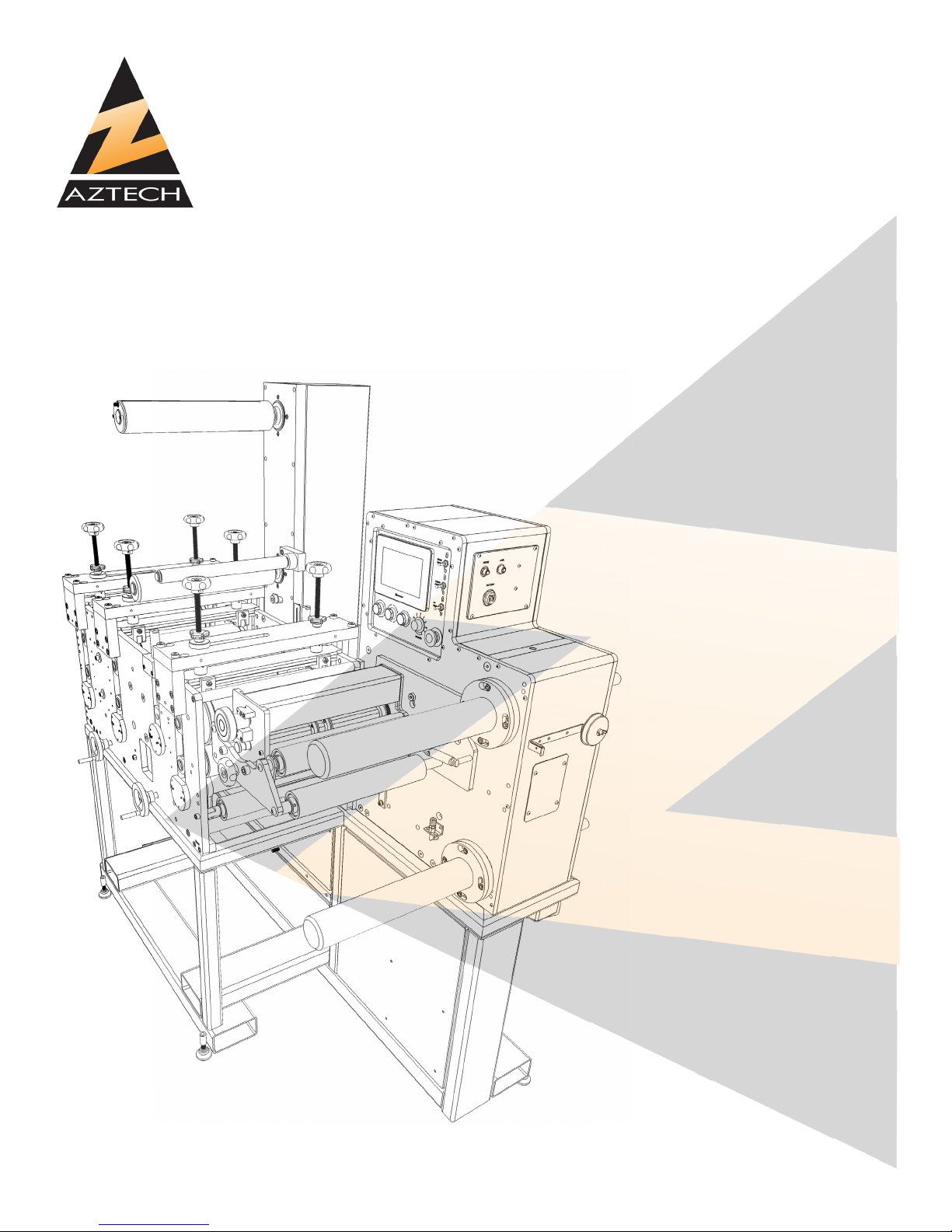
DIE MASTER
User Manual
DM-40XX
Ver 1.3
Page 2

AZTECH CONVERTING SYSTEMS
DM-40XX
USER MANUAL
TABLE OF CONTENTS
SECTION 1: GENERAL INFORMATION 1-4
SECTION 2: MACHINE INSTALLATION 4-5
SECTION 3: MACHINE SETUP 6-18
SECTION 4: MACHINE OPERATION 19-28
SECTION 5: MAINTENANCE 29
SECTION 6: STATION DETAIL 30-52
SECTION 7: TROUBLESHOOTING 53
SECTION 8: WARRANTIES AND SERVICE 54
Page 3
AZTECH CONVERTING SYSTEMS
DM-40XX
USER MANUAL
Section 1: General Information
1-1: Introduction
The AZTECH DieMaster Rotary Die Cutting Machine is available in 13 inch (33.02 cm), 18 inch
(45.72 cm) and 20 inch (50.8 cm) widths, with dual-spindle rewinds, and web speeds up to 500
feet/minute. The DieMaster is designed to be highly productive, versatile, and simple to operate
and maintain. Before operating your new DieMaster, fully read and understand all facets of this
manual. Following the procedures outlined in this manual will help assure maximum performance.
Keeping your machine properly set-up and maintained will assure years of productive and satisfactory service.
1-2: Machine Information and Specications
1
Page 4
AZTECH CONVERTING SYSTEMS
DM-40XX
USER MANUAL
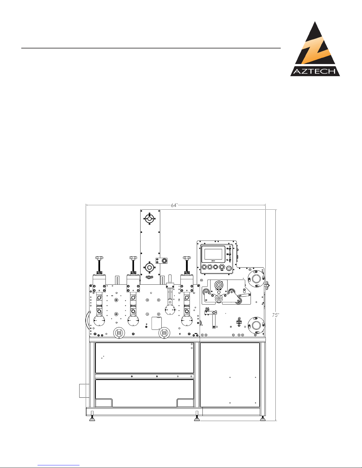
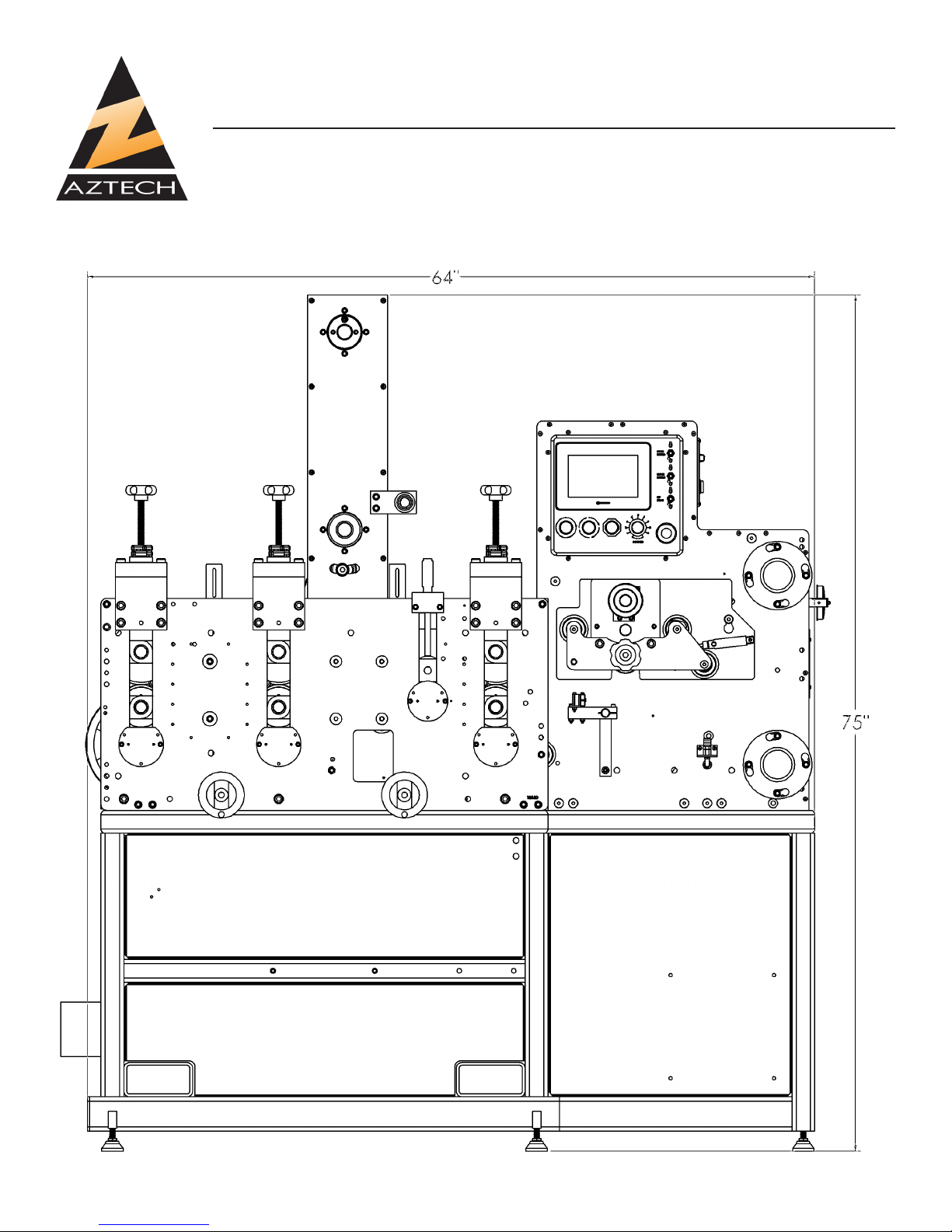
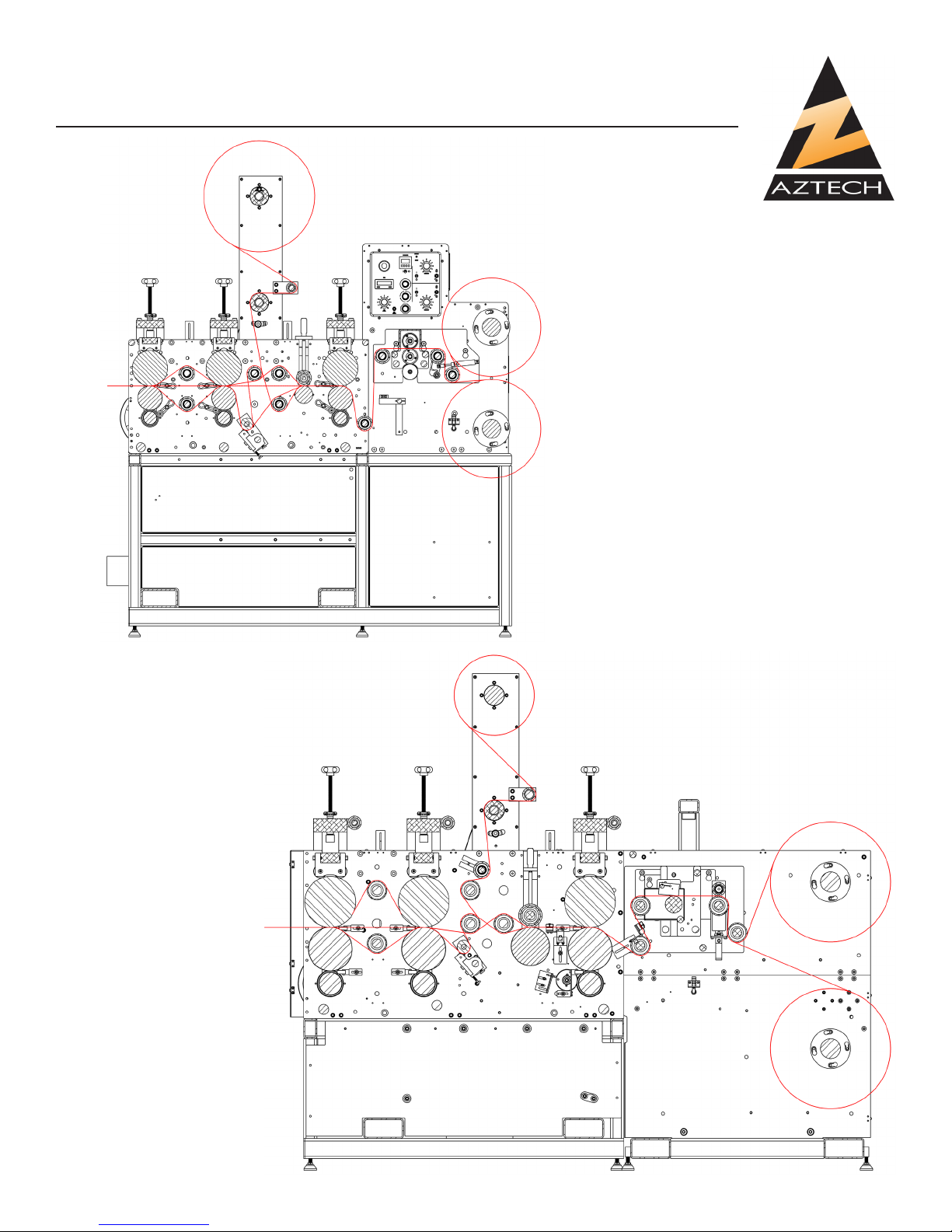
FRONT LAYOUT
(DIE MASTER ONLY)
2 Rev 1.3
Page 5
AZTECH CONVERTING SYSTEMS
DM-40XX
USER MANUAL
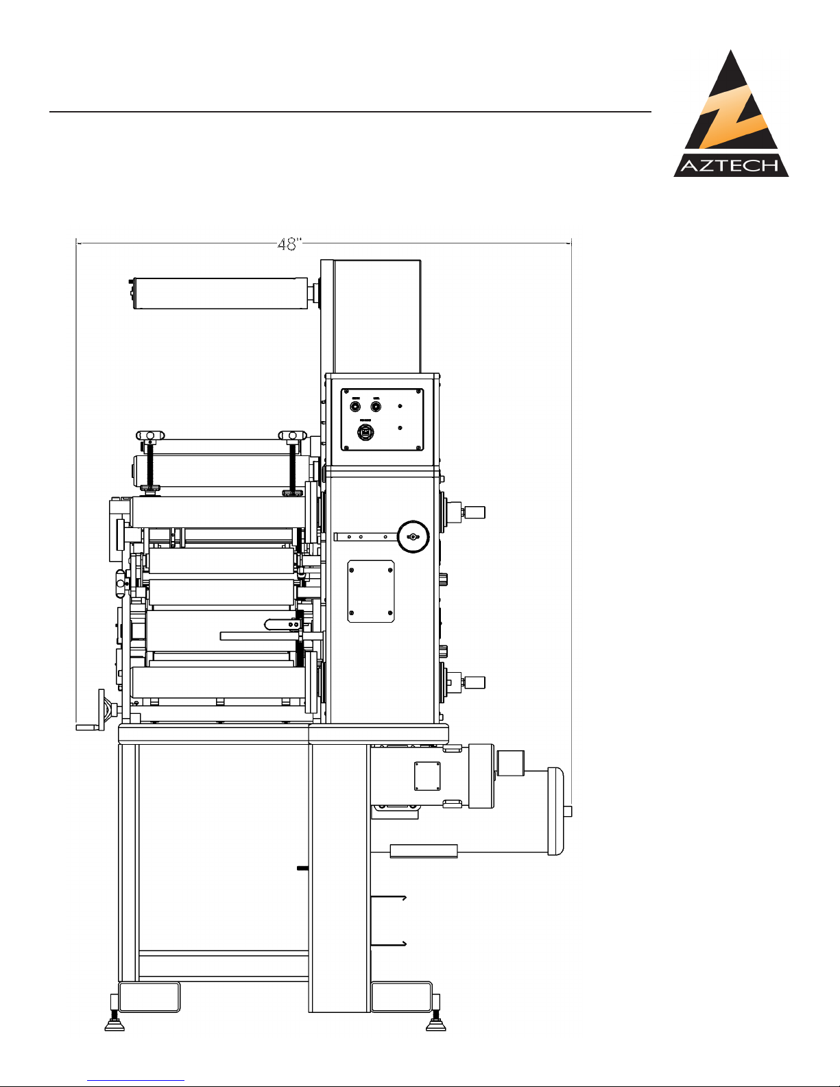
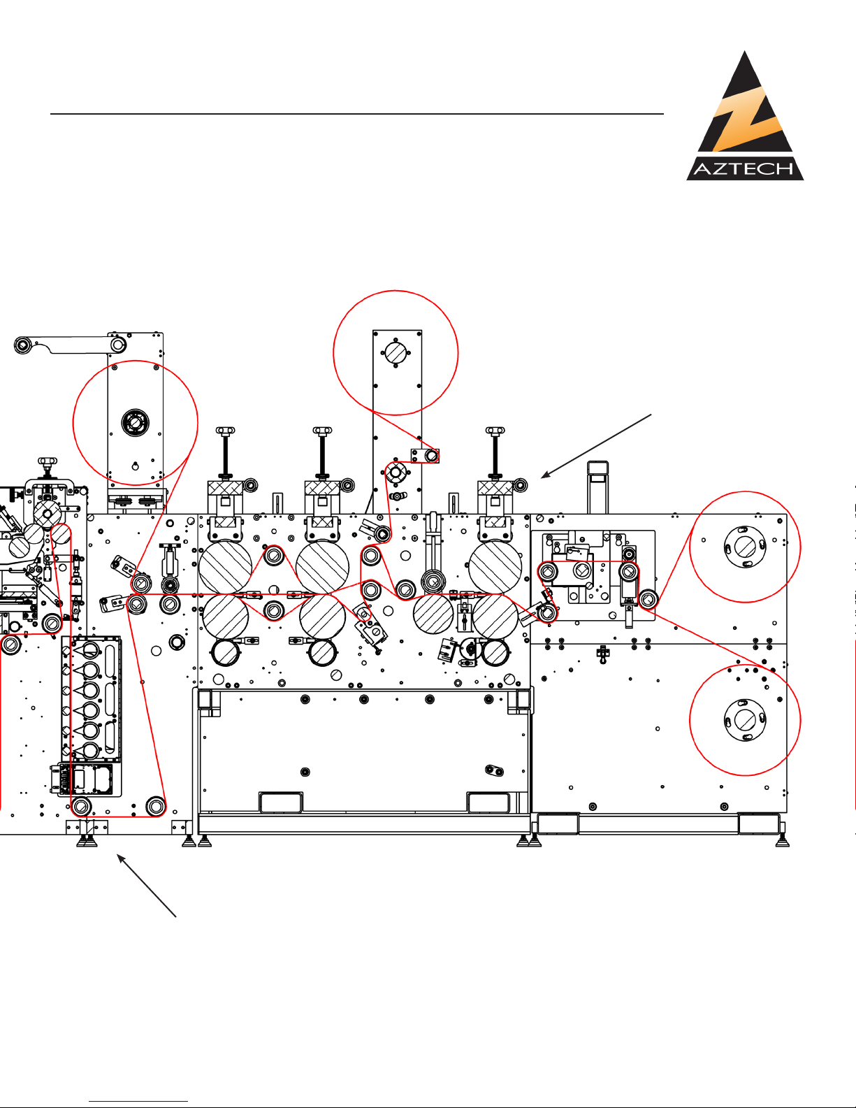
SIDE LAYOUT
(DIE MASTER ONLY)
(13” Shown, 18” and 20” are
similar)
3
Page 6

AZTECH CONVERTING SYSTEMS
DM-40XX
USER MANUAL
1-3: Care and Maintenance
To assure maximum performance and longevity of your Die Master, it is very important to perform periodic maintenance. Read
Chapter 5 for more information.
1-4: Safety
The DieMaster is designed to operate at high rates of speed, employing rollers, gears, pulleys, and
other moving parts. Where possible, guards are provided to protect operator from injury. Operators
must keep their hands clear of the machine when it is in operation. Making all operators aware of
potential safety hazards will help minimize any chances of operator injury.
Section 2: Machine Installation
2-1: Preparation
It is important that your DieMaster Rotary Die Cutter be situated on solid and level ground. Make
sure that site allows for access to machine from all 4 sides. If the machine is placed on unstable or
un-level ground, it may tip over risking damage or serious personal injury.
2-2: Un-crating Machine
To avoid damage to your new DieMaster, begin by unfastening the latches on the front panel and
removing the panel to expose the machine. Carefully remove all boxes from inside the crate and
set aside to avoid damage. Remove all 4 lag bolts which hold the machine to the base.
2-3: Removal and Positioning
It is critical that the DieMaster be removed from the crate using a fork lift, making sure that the forks
t directly inside the 2 slots at base of the machine. Lift and remove from crate, and if equipped with
adjustable feet, thread all 4 feet into threaded holes at machine’s base, and lower into desired position. Machine may be leveled by turning adjustable feet until level.
2-4: Electrical and Pneumatic Connections
50A 220VAC
THREE PHASE
TO DISCONNECT
ELECTRICAL CONNECTIONS: Your DieMaster uses
a power supply of 220 volts, 50 amps AC 3PH. Improper connections or mishandling may cause serious personal injury. AZTECH highly recommends that
electrical service be performed only by a qualied
electrician.
Electrical connection to the machine is performed
by bringing electrical service to the electrical box at
the back of the machine and making connections as
shown.
4 Rev 1.3
Page 7
AZTECH CONVERTING SYSTEMS
DM-40XX
USER MANUAL
90PSI
INCOMING
HP AIR
PNEUMATIC CONNECTIONS: Although
your machine has been thoroughly tested
before shipment, connections on occasion
may loosen during shipment. Visually inspect
all pneumatic to assure that each is tted
securely. Connect airline to the pneumatic
control panel at the back of the machine (see
gure 2-B), and listen for any air leaks that
may exist. Check all switches by switching
back and forth from on and off to make sure
they are operating properly.
NOTE: Red lines on air dials indicate proper default settings.
2-5: Testing Before Operation
Make sure the area around your machine is clear of any objects which may impair the machine.
Also inspect and make sure all belts, pulleys, rollers, and spindles are free and clear of any
objects which may impede operation, and risk machine damage. Before threading your machine,
accelerate and decelerate your machine through a full range of speeds, and make sure acceleration is smooth and free of any unnatural sounds or movements. Using control switches, switch
Unwind and Rewind Spindle(s) from on and off positions making sure the pneumatic system is
performing properly. Then turn power on, run machine at low speed to assure machine is working
properly. Then with speed set at maximum setting, press the stop button to assure that the brake is
working properly.
5
Page 8
AZTECH CONVERTING SYSTEMS
DM-40XX
USER MANUAL
Section 3: Machine Setup
3-1: Webbing the Machine
Proper webbing of your DieMaster is vital to optimal machine performance. The proper way to
thread your machine for various substrates is shown on the following page. Any improper webbing
of the machine may cause tension problems that will impede operation.
To web the machine:
1. Turn unwind arbor switch to
“DEFLATE” position.
2. Assure that the rewind and
unwind switches on main panel are in the “OFF” position
3. Assure that both splice-table
clamps are released into the
up position.
4. Assure that the pneumatic nip
roll is disengaged in the up
position.
5. Assure that the slitting blades
are disengaged. BE SURE
TO USE CAUTION WHEN
NEAR RAZOR SLITTING
BLADES AS THEY ARE
EXTREMELY SHARP AND
MAY CAUSE SERIOUS INJURY.
6. Load roll onto unwind spindle and carefully thread the web through the machine making sure to
follow web paths on the following page.
Modular Design
6 Rev 1.3
The Die Master press is designed
in modular sections to allow a
press to be tailored for an application. The various sections are
shown on the following pages.
Page 9
AZTECH CONVERTING SYSTEMS
DM-40XX
USER MANUAL
Unwind Sections
Cradle Mount
Unwind
CMU
Unwind Disc Brake
UDB
7
Page 10
AZTECH CONVERTING SYSTEMS
DM-40XX
USER MANUAL
Flexo Print Station
8 Rev 1.3
Lamination Tower
ACCESSORY MODULES
Page 11
AZTECH CONVERTING SYSTEMS
DM-40XX
USER MANUAL
DIE SECTIONS
13” - 18” DIE MASTER
20” DIE MASTER
9
Page 12
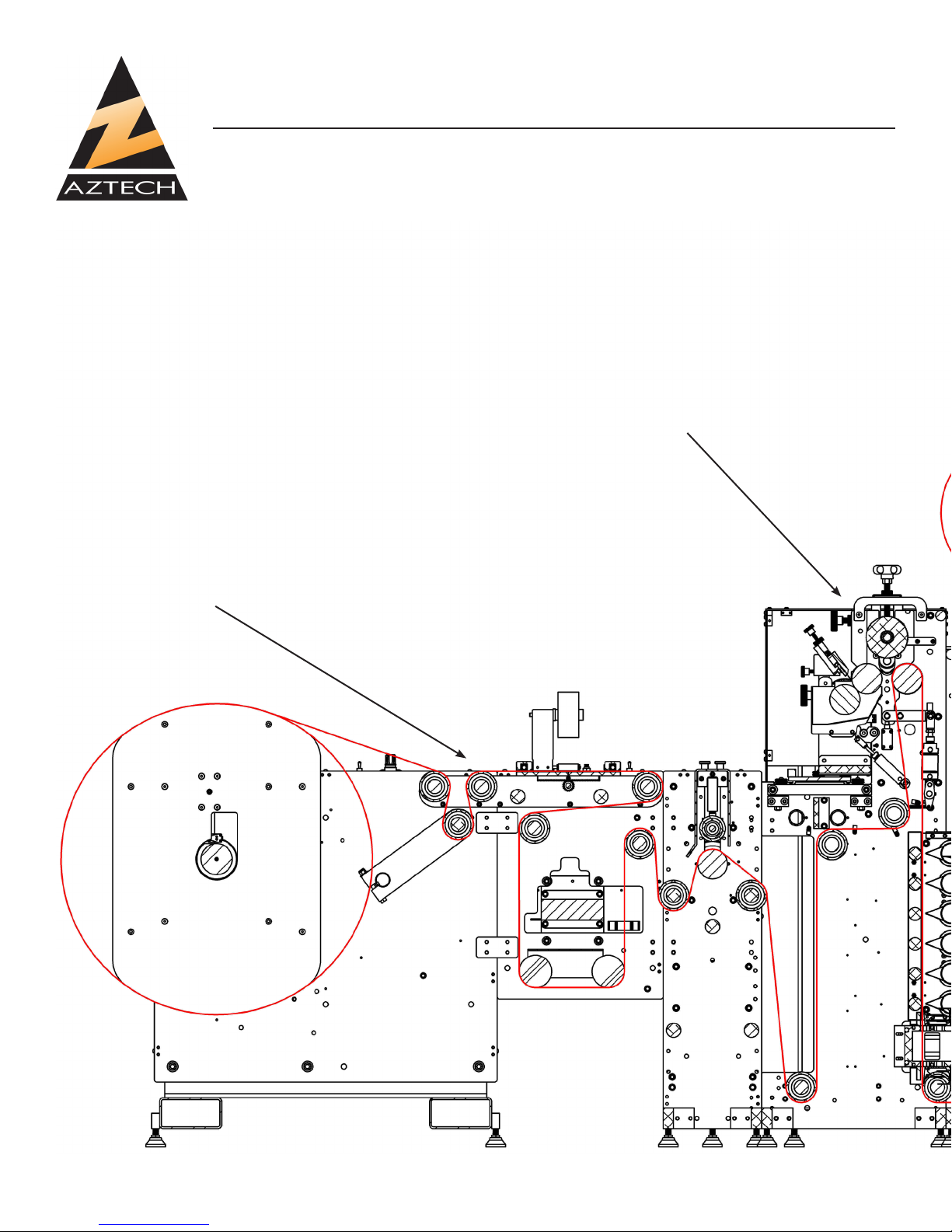
13” Die Master Shown
-UDB
-Print Station
-Lamination Tower
-13” Die Section
AZTECH CONVERTING SYSTEMS
DM-40XX
USER MANUAL
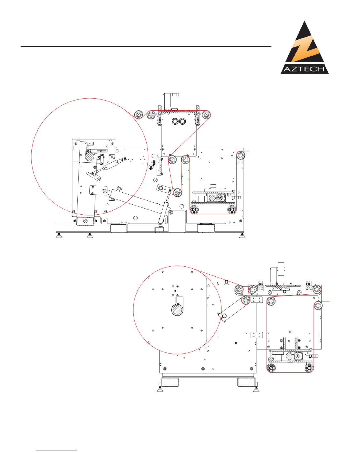
DieMaster w/ UDB Web Path
PRINT STATION
UDB
10 Rev 1.3
Page 13
AZTECH CONVERTING SYSTEMS
DM-40XX
USER MANUAL
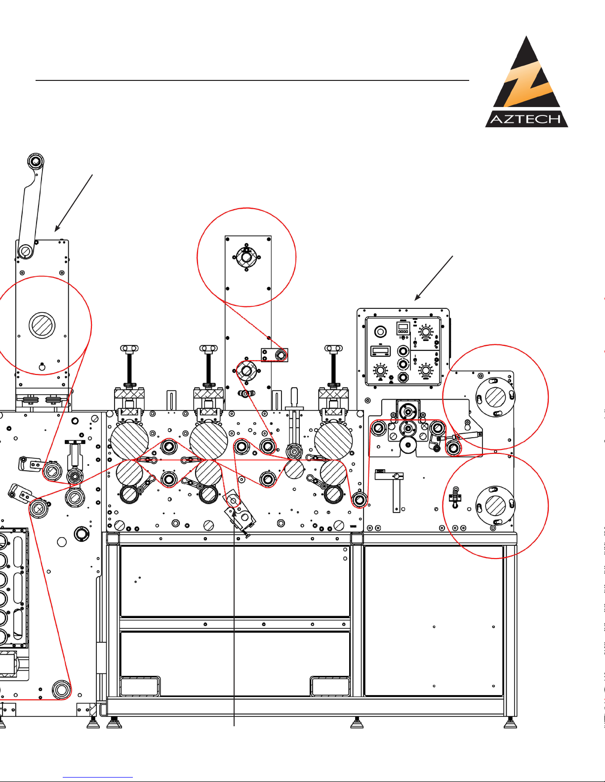
OPTIONAL WEB PATHS
LAMINATION TOWER
REWIND MODULE
SHOWN DASHED
UNDERSCORE
11
Page 14
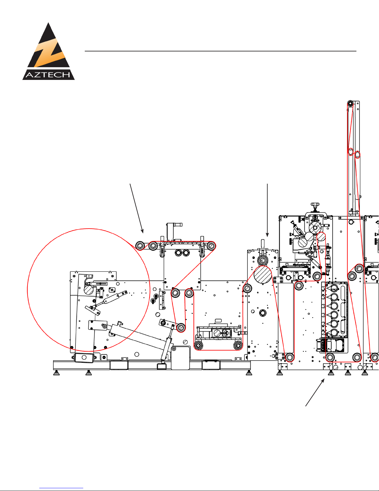
13” Die Master Shown
-CMU
-2x Print Stations
-Lamination Tower
-20” Die Section
AZTECH CONVERTING SYSTEMS
DM-40XX
USER MANUAL
CMU INFEED NIP
SAMPLE 20” PRESS
12 Rev 1.3
PRINT STATIONS
Page 15
AZTECH CONVERTING SYSTEMS
DM-40XX
USER MANUAL
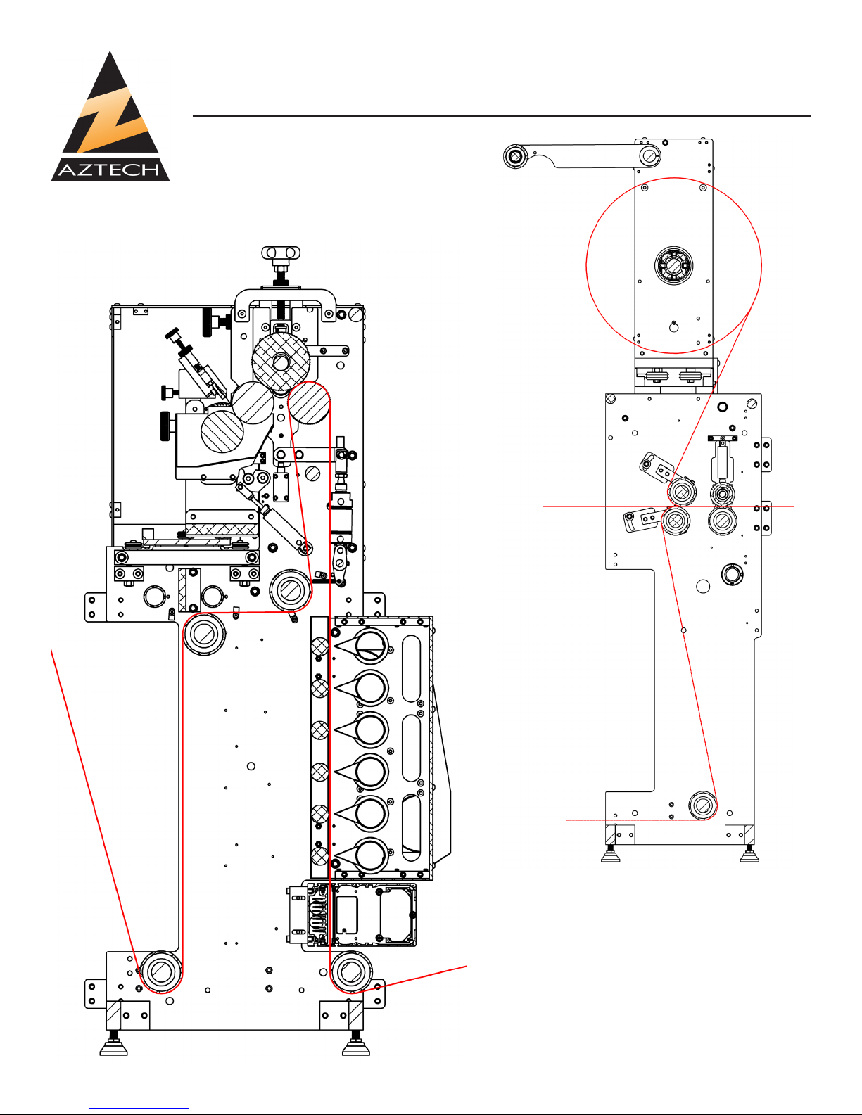
OPTIONAL WEB PATHS
20” DIE SECTIONS
SHOWN DASHED
Lamination Tower
13
Page 16
AZTECH CONVERTING SYSTEMS
DM-40XX
USER MANUAL
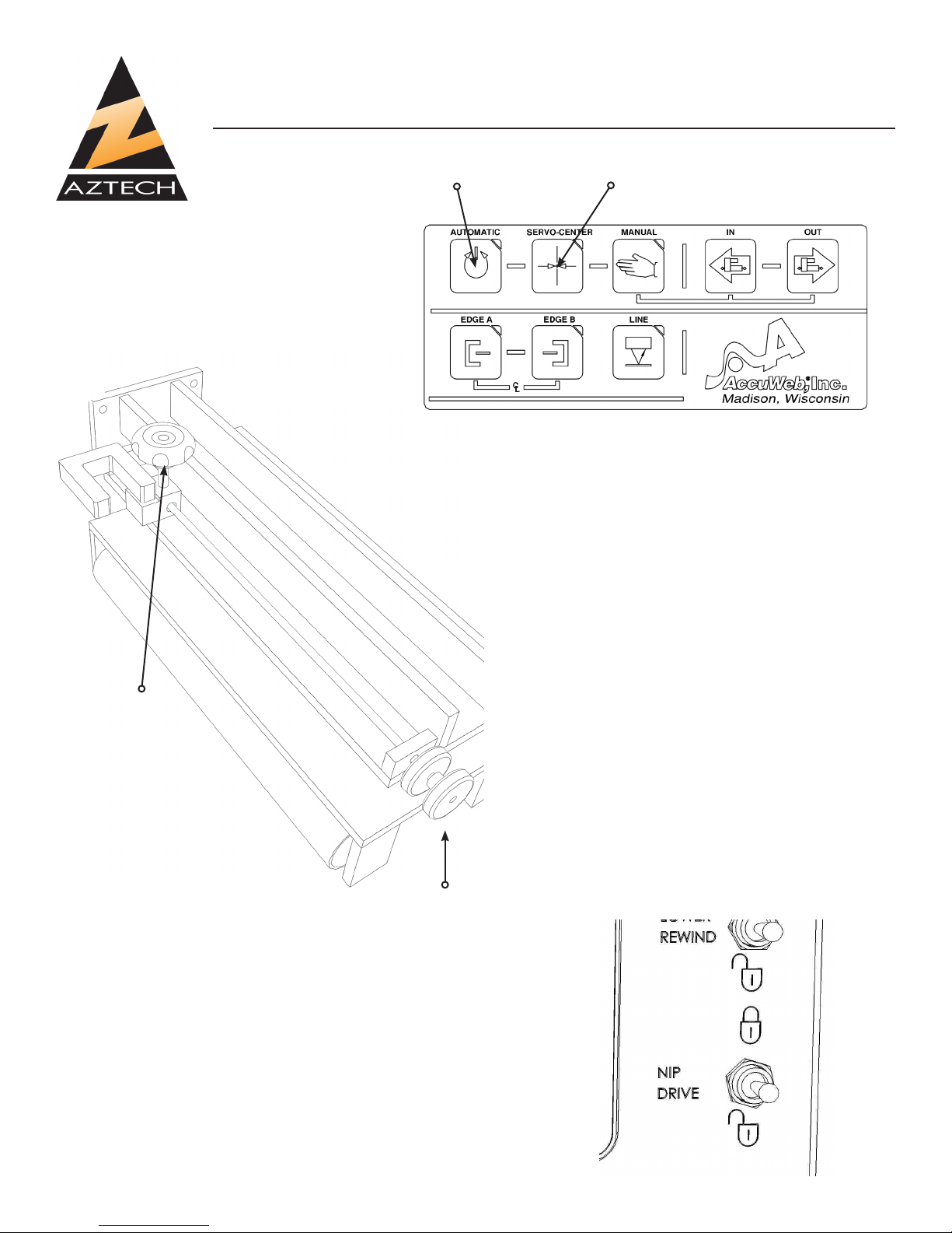
AUTOMATIC SERVO CENTER
3-2: Web Guide Setup
The web guide is located in the center of
the machine between the unwind and rewind stations. After webbing the machine,
set the web by doing the following:
COARSE
SENSOR
POSITIONING
Setting the Web Guide:
1. Press the “SERVO-CENTER” button on the
front of the web guide.
2. Align the sensor with the inside edge of the
web. For ne alignment adjustment, turn
knob on outside of web guide.
3. Jog the machine briey to assure that the
web is moving smoothly.
4. Press the “AUTOMATIC” button which
will engage the sensor and allow the web
guide to adjust itself to the movement of
the web.
5. For more specic instructions about the
features of the web guide, refer to the Accu-Web manual included with this manual.
3-3: Nip Roll Operation
The Nip Roll is pneumatically controlled using control switch and
must be in the up position while machine is running, and in the
down position when threading machine.
14 Rev 1.3
FINE
SENSOR
POSITIONING
Page 17
AZTECH CONVERTING SYSTEMS
DM-40XX
USER MANUAL
3-4: Splice Table Operation
The splice table on your Sidewinder BSR is located just above the
Unwind Station, just after the optional Inspection Tower. To operate
the Splice Table, simply follow the following steps:
WEB CLAMP
SWITCHES
SLITTING CHANNEL
1. Turn off machine and engage both web clamp switches.
2. Using a razor blade, carefully cut the web along the slicing channel. Disengage the clamp nearest the unwind station. Be sure to leave the other clamp engaged.
3. After waste has been removed, pull through new web, carefully align with web, and lower the
handle to hold.
4. Again using a razor blade, cut the web, discard waste, pull tape under webs, fold to secure and
cut tape.
5. Disengage both switches to release web clamps.
15
Page 18

AZTECH CONVERTING SYSTEMS
DM-40XX
USER MANUAL
3-5: ROTARY SHEAR SET-UP
Step 1 Set lower blades for
desired slit-widths and tighten
set-screws, making sure upper
blades are up and not in lock
position.
TURN TO UNLOCK
Step 2 Lower upper blade
assembly by turning handle
counter-clockwise and snap
into lock position, making sure
that the upper blades are clear
of lower blades to avoid blade
damage.
Step 3 Gently slide upper
blade(s) into cutting position
ush against the lower blade(s)
by pushing on both sides of the
blade to avoid wobble. Hold upper blade against lower blade
and tighten set-screw.
SLITTER
TIGHTEN SET SCREWS
TO LOCK BLADES
16 Rev 1.3
Page 19

AZTECH CONVERTING SYSTEMS
DM-40XX
USER MANUAL
LOOSEN SET
SCREW HERE
SLIDE FORWARD
TO REMOVE
3-6: Changing Rewind Spindle
Your Die Master may be equipped with Convertech pneumatically inatable modular rewind spindles. These spindles are easily removed by loosening the hex-screw at the machine side and pulling away from machine. To insert new spindle, simply insert spindle into rewind station and tighten
hex-screw rmly.
CAUTION: Utilizing Rewind Spindles less than 1.5” in diameter require the use of Outboard
Support Apparatus which is NOT included in the standard equipment. Operating the machine without the support apparatus and with spindles less than 1.5” may result in serious
injury.
17
Page 20

ADJUST EOR HEIGHT
AZTECH CONVERTING SYSTEMS
DM-40XX
USER MANUAL
LOOSEN SET
SCREW HERE
CMU EOR Sensor Mounting
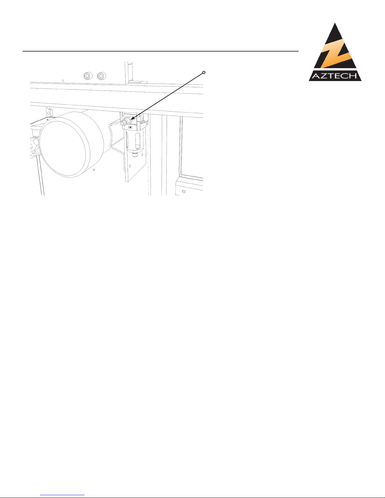
3-7: End-of-Roll (EOR) Sensor Adjustment
The unwind unit will come equipped with an end-
of-roll sensor. When this sensor is switched on,
the machine will not RUN if there is insufcient
material on the unwind roll. To adjust the sensor:
1: Loosen the screw retaining the EOR sensor
mount.
2: Move the sensor into a position where it is just
“OFF” with an empty core.
3: Tighten the retaining screw.
ADJUST EOR HEIGHT
18 Rev 1.3
UDB EOR Sensor Mounting
Page 21

AZTECH CONVERTING SYSTEMS
DM-40XX
USER MANUAL
Section 4: Machine Operation
4-1: Operator Control Layout
13”- 18” Standard model DieMaster
START PB
JOG PB
STOP PB
SPEED KNOB
REWIND CONTROLS
COUNTER CONTROL
E-STOP
20” Standard model DieMaster
19
Page 22

AZTECH CONVERTING SYSTEMS
DM-40XX
USER MANUAL
4-1: Operator Control Layout
TOUCH
SCREEN
PLC
The Die-Master is also available with a PLC machine control with
a touch-screen interface. The operation of the HMI interface is
described in the next section.
20 Rev 1.3
START PB
JOG PB
STOP PB
SPEED KNOB
REWIND CONTROLS
AIR CONTROLS
E-STOP
Page 23

AZTECH CONVERTING SYSTEMS
DM-40XX
USER MANUAL
4-2: PLC OPERATION
THE MAIN MENU
On power-up of the machine, the PLC will boot. This is analogous to a home PC booting. It can be
expected to take a minute or two.
When the PLC has nished booting, the MAIN MENU will be displayed.
When the MAIN MENU is displayed, the PLC will lock-out the operator buttons and the machine will
not run.
The menu jumps displayed in white may be accessed by the user, the yellow MACHINE DIAGNOSTICS jump is password protected.
The PLC may be setup to have controls labeled in Spanish or German. Pressing the ags at the
bottom changes between these languages.
21
Page 24

MAIN MENU
Buttons to acess primary ma-
chine functions are displayed
AZTECH CONVERTING SYSTEMS
DM-40XX
USER MANUAL
RUN SCREEN
on the MAIN MENU.
Menú principal en Español Hauptmenu auf Deutsch
22 Rev 1.3
Page 25

AZTECH CONVERTING SYSTEMS
DM-40XX
USER MANUAL
RUN MENU
Set Torque. Press
to set manually
Machine Running Status
Enabled/Disabled Indicator
Adjustor / Indicator
Increment by 1 and 10
Counter ON/OFF
Exit to Main Menu Prompt Rewind Setup
Progress BarDistance Units
Count Sensor Selection
23
Page 26

AZTECH CONVERTING SYSTEMS
DM-40XX
USER MANUAL
COUNTER STATUS
DISPLAY
The user is prompted to con-
rm reset. The prompt clears in
5 seconds.
The Batch Count increments
every time the set count is
reached and the counter is on.
Press here to turn the
counter on and off.
The current count is displayed The Set count is displayed
The count progress is visually
represented as a percentage
scale.
The count sensor selection is
shown. If in distance, the units
are displayed.
24 Rev 1.3
Page 27

AZTECH CONVERTING SYSTEMS
DM-40XX
USER MANUAL
Press the box to change between
Over and Underwind.
DO NOT SWITCH WHILE RUNNING
TORQUE COMPENSATION
The Torque Compensation feature mimics the act of slowly increasing rewind torque by gradually
turning up the knob while the roll grows. To set up the feature, enter the core diameter as the Start-
ing Diameter. Enter the nished roll size as the Finishing Diameter. Subtract the torque setting
used to start the roll from the setting used to nish the roll and enter this as the % to ADD. When
the TQ COMP is on, a text will be displayed above the rewind torque bar.
25
Page 28

AZTECH CONVERTING SYSTEMS
DM-40XX
USER MANUAL
Press to set the nish count.
Press to set the slowdown
point. IF THE SLOWDOWN
POINT IS GREATER THAN
THE SET COUNT, THE
MACHINE WILL NOT SLOWDOWN.
When in distance count, press
to set the units.
26 Rev 1.3
Press to toggle between
count sensors.
Press to turn the EOR on
and off.
When the End of Roll sensor is
on, an indicator showing its status
will show on the Run Menu.
Page 29

AZTECH CONVERTING SYSTEMS
DM-40XX
USER MANUAL
4-3: Mounting Rotary Die(s) in Die Station
Recapping the set-up procedures as outlined in Chapter 3, carefully follow the web path diagram in 3.1-2, web the DieMaster,
and adjust the web guide if needed (see diagram 3-2).
ALWAYS USE CAUTION WHEN HANDLING ROTARY TOOLING
AS DAMAGE MAY OCCUR IF MISHANDLED. WHEN LAYING A
ROTARY DIE DOWN, ALWAYS MAKE SURE TO SET ON SOFT
SURFACE TO HELP AVOID DAMAGE.
To correctly mount a rotary die:
1) Use spacer washer(s) on journal on gear side to assure that
the die gear is properly aligned to the anvil roll gear.
2) Slide square bearing block onto gear side journal and slide die
into place. If gears are not aligned properly, remove die, and add
or remove washers until aligned.
3) Use spacer washer(s) on outboard side, and slide quarter-turn
bearing block onto shaft and turn counter-clockwise, making certain that the die is snug and does not slide around.
4) With die in proper position, set die truck onto die making certain the bearings ride against the rotary die bearers.
5) Slide die bridge into place, tighten all 4 hex screws, and turn
both assist knobs clockwise until snug. Secure die by turning the
lock knobs clockwise until tight.
6) Using the pre-drilled holes near the die station, secure the 4
die wipers against the die bearers and lubricate all 4 with oil to
help keep debris away from die.
27
Page 30

AZTECH CONVERTING SYSTEMS
DM-40XX
USER MANUAL
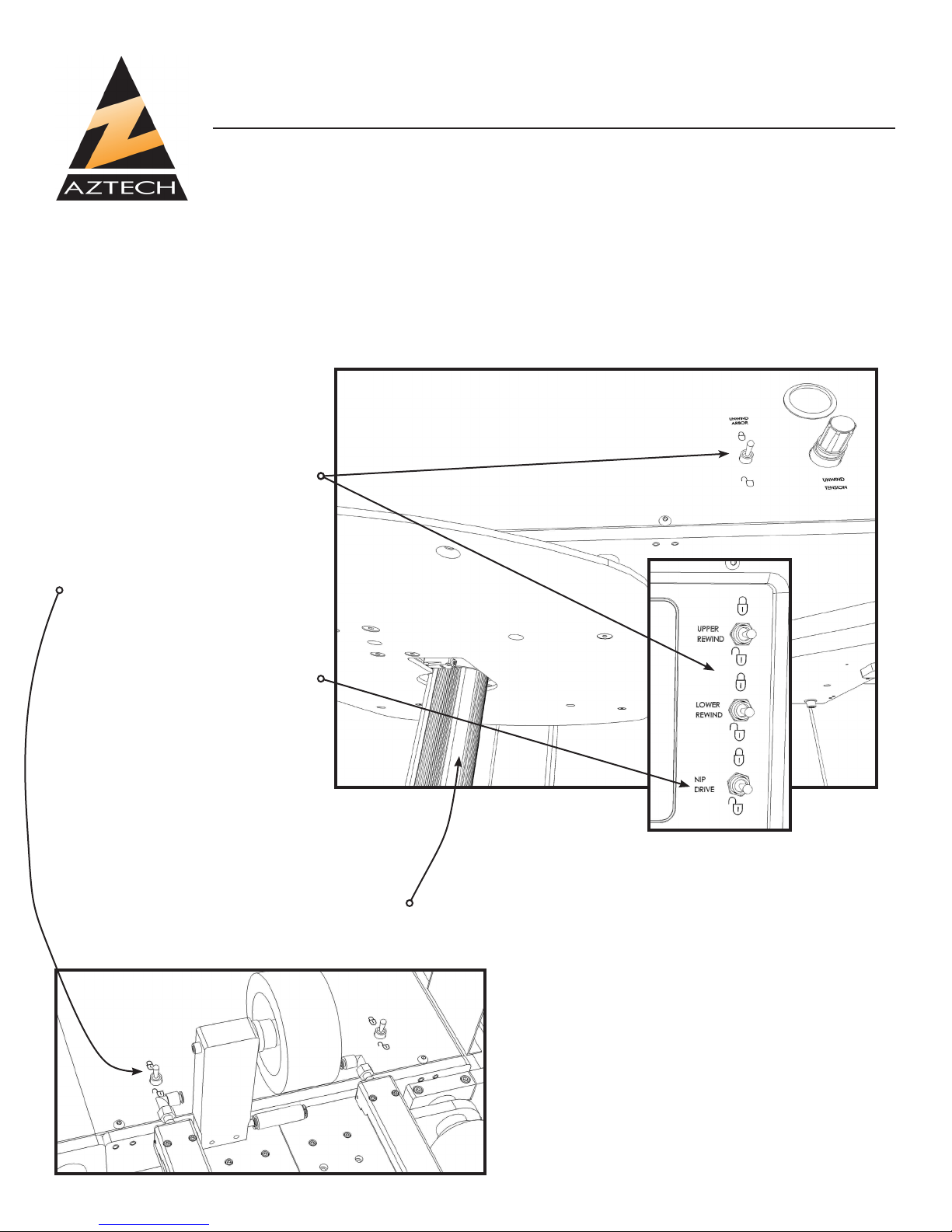
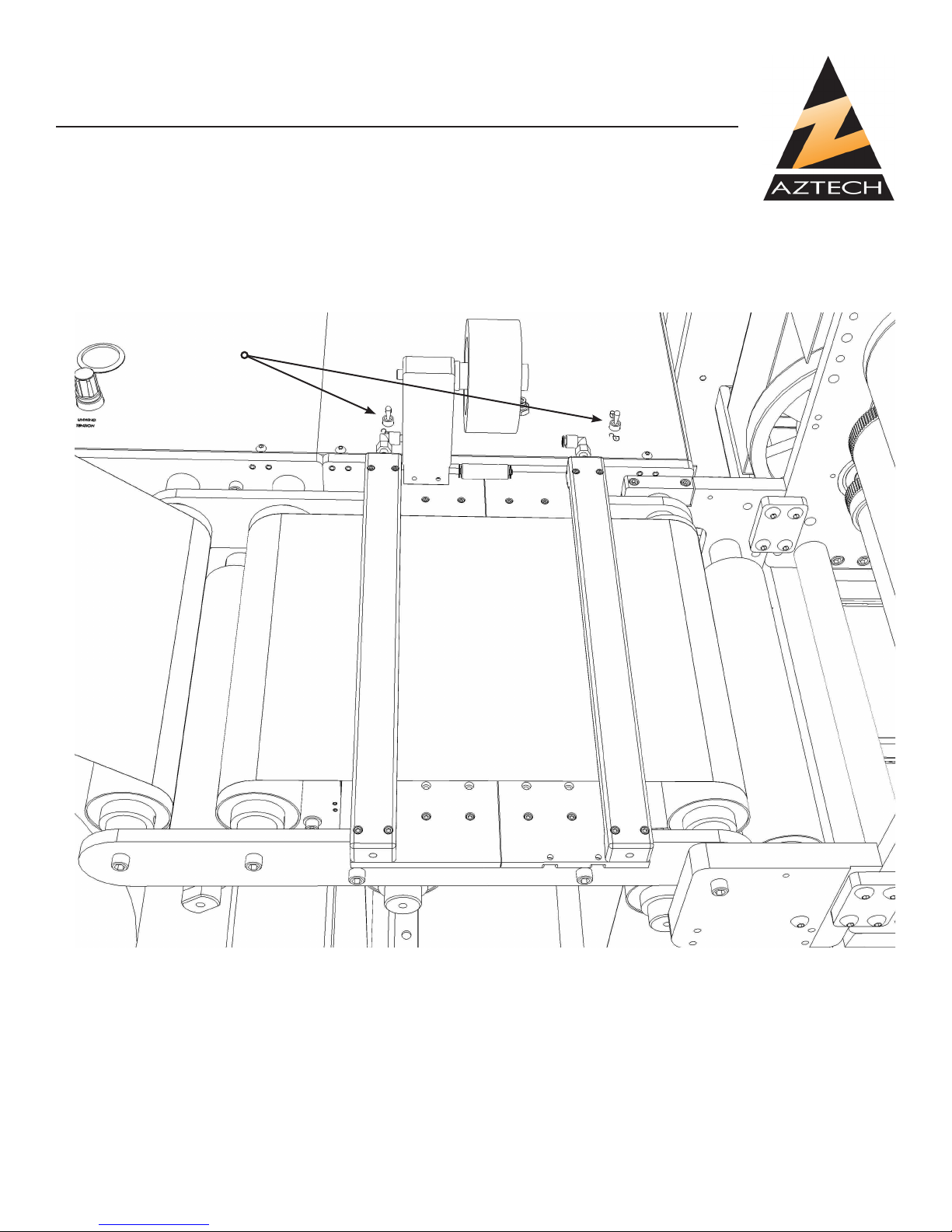
4-4: Using the Waste-Windup
With die properly positioned, slide a core onto the waste-windup
spindle, inate using the switch and perform the following steps:
1) Jog the machine to briey begin cutting and
than stop.
2) Peel the waste away from the web, using
caution by keeping hands away from the die,
and hold with one hand while jogging the
machine to produce enough length of waste to
reach the waste wind-up.
3) Thread the waste by wrapping around the
capstain roll, then around the knurled idler roll,
before securing to the waste windup spindle.
4) Adjust both lower capstan and waste-windup spindle tensions using the pneumatic dials.
CAUTION: ALWAYS KEEP HANDS OR LOOSE CLOTHING AWAY FROM THE DIE WHEN THE
MACHINE IS IN MOTION TO AVOID THE POTENTIAL FOR SERIOUS PERSONAL INJURY.
4-5: Adjusting Die Timing
The cranks at the front of the machine may be used
to adjust the die timing.
Timing position is shown by the bar and scale are
the top rear of the machine.
28 Rev 1.3
Page 31

AZTECH CONVERTING SYSTEMS
DM-40XX
USER MANUAL
Chapter 5: Maintenance
The DieMaster Rotary Die Cutting Machine is rigidly constructed to provide your company many
years of reliable productivity, however regular and periodic maintenance is required to keep it running to its full potential and to avoid damage. To assure maximum performance and longevity, the
following maintenance is essential:
REGULAR MAINTENANCE:
• Lubricate Die and Anvil Roll bearing blocks by applying oil into holes at the top of the bearing
blocks.
• Apply oil to all ber wiper rolls to keep dies and rollers free of debris.
• Apply heavy viscosity gear grease to all roller gears.
• Apply grease to the die trucks using the (4) ttings and apply oil to the felt pads between the bear-
ings and trucks.
• Clean blades on slitting station.
PERIODIC MAINTENANCE:
• Turn off power and remove back cover to inspect all belts assuring they are tightened sufciently.
• Clean the web guide sensor to assure that it is free of dust and debris.
• Clean counter sensors inside the machine under the pace roller to assure that they are free of
dust and debris.
• Assure that all belts are sufciently tight and tighten any loose belts.
29
Page 32

AZTECH CONVERTING SYSTEMS
DM-40XX
USER MANUAL
Chapter 6: Station Detail
UDB Main Assembly
30 Rev 1.3
Page 33

AZTECH CONVERTING SYSTEMS
DM-40XX
USER MANUAL
31
Page 34

AZTECH CONVERTING SYSTEMS
DM-40XX
USER MANUAL
UBD: Brake Assembly
32 Rev 1.3
Page 35

AZTECH CONVERTING SYSTEMS
DM-40XX
USER MANUAL
33
Page 36

AZTECH CONVERTING SYSTEMS
DM-40XX
USER MANUAL
UDB: Brake Assembly
34 Rev 1.3
Page 37
AZTECH CONVERTING SYSTEMS
DM-40XX
USER MANUAL
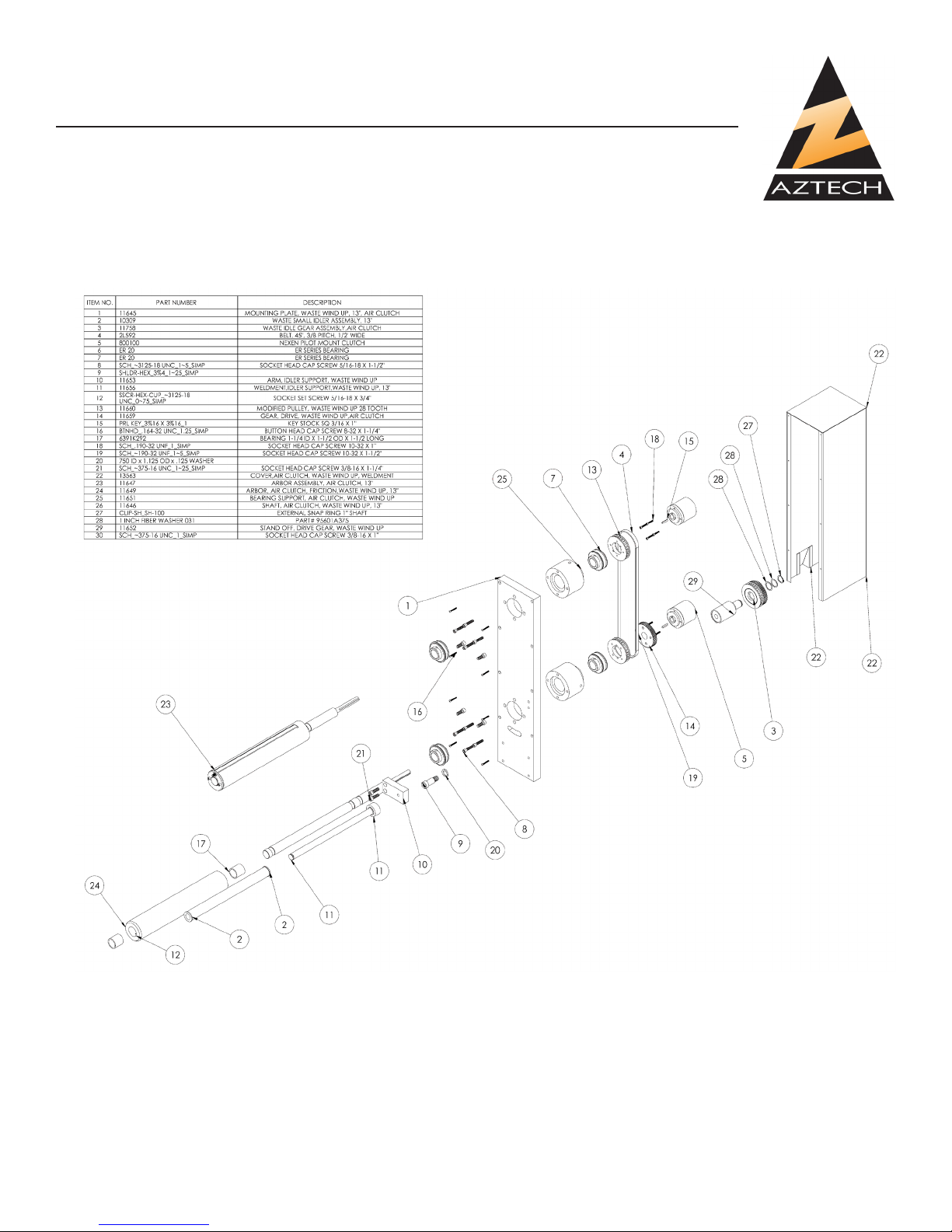
Waste Windup Assembly
35
Page 38

AZTECH CONVERTING SYSTEMS
DM-40XX
USER MANUAL
Rotary Die Station: Support Roll Assembly
36 Rev 1.3
Page 39

AZTECH CONVERTING SYSTEMS
DM-40XX
USER MANUAL
Rotary Die Station: Anvil Roll Assembly
37
Page 40

AZTECH CONVERTING SYSTEMS
DM-40XX
USER MANUAL
Rotary Die Station: Die Truck Assembly
38 Rev 1.3
Page 41

AZTECH CONVERTING SYSTEMS
DM-40XX
USER MANUAL
Main Drive: Nip Roll Assembly
39
Page 42

AZTECH CONVERTING SYSTEMS
DM-40XX
USER MANUAL
Main Drive: Pace Roll Assembly
40 Rev 1.3
Page 43

AZTECH CONVERTING SYSTEMS
DM-40XX
USER MANUAL
Slitting Station: Main Assembly
41
Page 44

AZTECH CONVERTING SYSTEMS
DM-40XX
USER MANUAL
Slitting Station: Rotary Shear Assembly
42 Rev 1.3
Page 45

AZTECH CONVERTING SYSTEMS
DM-40XX
USER MANUAL
Press Controls, PLC OPTION
43
Page 46

AZTECH CONVERTING SYSTEMS
DM-40XX
USER MANUAL
Main Electrical Cabinet, PLC
44 Rev 1.3
Page 47

AZTECH CONVERTING SYSTEMS
DM-40XX
USER MANUAL
Label Sensor Panel
Operator Panel, PLC
45
Page 48

AZTECH CONVERTING SYSTEMS
DM-40XX
USER MANUAL
Cradle Mount Unwind Controls
46 Rev 1.3
Page 49

AZTECH CONVERTING SYSTEMS
DM-40XX
USER MANUAL
47
Page 50

AZTECH CONVERTING SYSTEMS
DM-40XX
USER MANUAL
Press Controls, STANDARD
48 Rev 1.3
Page 51

AZTECH CONVERTING SYSTEMS
DM-40XX
USER MANUAL
Press Schematic, STANDARD
49
Page 52

AZTECH CONVERTING SYSTEMS
DM-40XX
USER MANUAL
Press Schematic, STANDARD
50 Rev 1.3
Page 53

AZTECH CONVERTING SYSTEMS
DM-40XX
USER MANUAL
51
Page 54

AZTECH CONVERTING SYSTEMS
DM-40XX
USER MANUAL
Press Schematic, STANDARD
52 Rev 1.3
Page 55

AZTECH CONVERTING SYSTEMS
DM-40XX
USER MANUAL
Section 7: Troubleshooting
7-1: Why doesn’t the machine turn on?
First check to make sure that the main power switch on the back electrical panel is turned on. Then
make sure that the emergency stop button on control panel is
disengaged.
7-2: The counter is not counting accurately.
Inspect and clean both counter sensors located in the machine on the gear underneath the pace
roller.
7-3: Why is the counter not counting inches?
Make sure that the counter sensor below the web guide is ashing red which assures that it is properly connected to the machine. Be sure that the setting on the PLC is “Distance”.
7-4: Why is the counter not counting labels?
If your machine is equipped with the optional label counter and is not doing so, after assuring that
the counter sensor below the web guide is ashing red which assures
that it is properly connected, assure that the PLC is set to “LABELS”.
7-5: Why isn’t the end-of-roll sensor working?
If your DieMaster is equipped with the optional end-of-roll shut-down and it is not shutting down
the machine when the unwind roll is near the end, or if it is shutting down prematurely, perform the
following:
1. Assure that the light on the sensor (see gure 7-B)
located near the unwind spindle is illuminated.
2. If not illuminated, check wiring for proper connections or damage. If wiring is set up properly, the
sensor may need to be replaced.
3. If illuminated, the sensor may be in need of adjustment. If the machine is shutting down prematurely, the sensor needs to be moved closer to the
unwind spindle, where if it is not shutting down
the machine at all, the sensor needs to be moved
away from the unwind spindle. To adjust the sensor, simply loosen the set screw, slide bracket in
either direction, and re-tighten
Adjust Sensor
Height
Set Screw
53
Page 56

AZTECH CONVERTING SYSTEMS
DM-40XX
USER MANUAL
Section 8: Warranties and Service
8-1: Warranties & Provisions
WARRANTIES: All equipment manufactured and sold by AZTECH Converting Systems (Seller) is
warranted to be free of defective materials and workmanship under normal use and service for a
period of one (1) year from the date of delivery to Buyer's premises. All commercial components not
manufactured by Seller carry the original manufacturer's warranty. At Seller's discretion, Seller may
provide on-site warranty service for a period of ninety (90) days from the aforementioned date.
REMEDIES If within the Warranty Period any such Equipment is proven to Seller's satisfaction to
be defective in either material or workmanship, Seller, at its sole discretion, shall (a) repair or re-
place defective parts on the Equipment at Seller's cost, or (b) grant a reasonable allowance on
account of such a breach. If within the Warranty Period the Seller receives notice from Buyer of
defects in parts or materials. Seller will ship (ground, prepaid) replacement parts) and invoice Buyer
for the full cost of the replacement parts). Buyer will receive a Return Authorization (RA) from seller,
and return defective parts or materials to Seller, who at its sole discretion shall determine whether
defective parts or materials are or are not subject to exclusion from this warranty as provided herein. Any defective parts or material not excluded from the Warranty Period will then be fully credited
to Buyer.
EXCLUSIONS
THE FOLLOWING ITEMS ARE EXCLUDED FROM THIS WARRANTY:
• Defects or damage caused by careless or improper use.
• Parts that need periodic replacement from wear during normal operation.
• Routine maintenance and adjustment.
• Failure or damage caused by improper
installation or inadequate maintenance by Buyer.
• Failure or damage caused by equipment modications by Buyer.
• Equipment damage resulting from an accident, or abnormal conditions of operation.
DISCLAIMER OR WARRANTY
NO OTHER WARRANTY IS EXPRESSED OR IMPLIED INCLUDING WARRANTIES OF MER-
CHANTABILITY AND FITNESS FOR ANY PARTICULAR PURPOSE. SELLER IS NOT LIABLE
FOR INCIDENTAL OR CONSEQUENTIAL DAMAGE SUCH AS, BUT NOT LIMITED TO LOSS IN
PROFITS, LOSS OF USE OF EQUIPMENT, OR INCREASED IN OPERATING COSTS OR EXPENSES.
8-2: Technical Service
In the event that your DM is not functioning properly or if you have any technical questions, an AZTECH Technical Service representative is available to assist you. Contact information is as follows:
Phone: 1-480-951-8351
1-800-829-8351
Fax: 1-480-998-5409
E-Mail: techservice@aztechconverting.com
54 Rev 1.3
 Loading...