

Page 1
Page 2

© Copyright 2017 All rights reserved.
No part of this document may be reproduced, republished, or retransmitted in any
form or by any means whatsoever, whether electronically or mechanically,
including, but not limited to, by way of photocopying, recording, information
recording, or through retrieval systems without the express written permission. We
reserve the right to revise this document at any time without the obligation to notify
any person and/or entity. All other company or product names mentioned are used
for identification purposes only and may be trademarks of their respective owners.
LIMITATION OF LIABILITY AND DAMAGES
THE PRODUCT AND THE SOFTWARES WITHIN ARE PROVIDED "AS IS," BASIS. THE
MANUFACTURER AND MANUFACTURER’S RESELLERS (COLLECTIVELY REFERRED TO AS
―THE SELLERS‖) DISCLAIM ALL WARRANTIES, EXPRESS, IMPLIED OR STATUTORY,
INCLUDING WITHOUT LIMITATION THE IMPLIED WARRANTIES OF NON-INFRINGEMENT,
MERCHANTABILITY OR FITNESS FOR A PARTICULAR PURPOSE, OR ANY WARRANTIES
ARISING FROM COURSE OF DEALING, COURSE OF PERFORMANCE, OR USAGE OF
TRADE. IN NO EVENT WILL THE SELLERS BE LIABLE FOR DAMAGES OR LOSS, INCLUDING
BUT NOT LIMITED TO DIRECT, INDIRECT, SPECIAL WILLFUL, PUNITIVE, INCIDENTAL,
EXEMPLARY, OR CONSEQUENTIAL, DAMAGES, DAMAGES FOR LOSS OF
BUSINESS PROFITS, OR DAMAGES FOR LOSS OF BUSINESS OF ANY CUSTOMER OR ANY
THIRD PARTY ARISING OUT OF THE USE OR THE INABILITY TO USE THE PRODUCT OR THE
SOFTWARES, INCLUDING BUT NOT LIMITED TO THOSE RESULTING FROM DEFECTS IN THE
PRODUCT OR SOFTWARE OR DOCUMENTATION, OR LOSS OR INACCURACY OF DATA
OF ANY KIND, WHETHER BASED ON CONTRACT, TORT OR ANY OTHER LEGAL THEORY,
EVEN IF THE PARTIES HAVE BEEN ADVISED OF THE POSSIBILITY OF SUCH DAMAGES. THE
ENTIRE RISK AS TO THE RESULTS AND PERFORMANCE OF THE PRODUCT OR ITS
SOFTWARE IS ASSUMED BY CUSTOMER. BECAUSE SOME STATES DO NOT ALLOW THE
EXCLUSION OR LIMITATION OF LIABLITY FOR DAMAGES, THE ABOVE LIMITATION MAY
NOT APPLY TO THE PARTIES. IN NO EVENT WILL THE SELLERS’ TOTAL CUMULATIVE
LIABILITY OF EACH AND EVERY KIND IN RELATION TO THE PRODUCT OR ITS SOFTWARE
EXCEED THE AMOUNT PAID BY CUSTOMER FOR THE PRODUCT.
Page 3

Contents
About the Router ............................................................................................................................... 3
Package Contents ........................................................................................................................ 5
Device Design ................................................................................................................................. 6
Getting Started ................................................................................................................................... 9
Plan your Network........................................................................................................................ 10
Remove/ Disable Conflicts ........................................................................................................ 11
Internet Sharing, Proxy, and Security Applications ............................................................ 11
Configuring TCP/IP Settings ....................................................................................................... 11
Configuring Internet Properties ................................................................................................ 12
Removing Temporary Internet Files......................................................................................... 12
Setup the Device ......................................................................................................................... 13
The Web User Interface .................................................................................................................. 14
Accessing the Web User Interface ......................................................................................... 14
Web User Interface...................................................................................................................... 15
Status Icons and Reboot button ............................................................................................. 15
Quick Setup Wizard ..................................................................................................................... 16
Basic ................................................................................................................................................ 23
Advanced ..................................................................................................................................... 46
AON Mesh .......................................................................................................................................... 89
AON Mesh Web User Interface ................................................................................................ 89
Mesh System Setup ...................................................................................................................... 91
Page 4

About the Router
Living in an era where wireless technology is of key importance and with the
introduction of fibre network, people are bombarded with different router
alternatives that aim to give the best. One has to find a router that accommodates
not only to the consistent growth in wireless devices one has at home but also to
meet the fast and reliable performance of a fibre optic cable connection. One of
the major challenges a router should be able to support is not only to distribute the
internet connection to a variety of devices but also to provide a seamless
connectivity with an exceptional Wi-Fi speed to match as well as excellent
coverage that will allow one to roam around their premises without getting
disconnected. And not forgetting to provide a gateway to the fibre network. With
careful consideration to these ever growing needs, Aztech developed the AIR-706P,
a Dual Band Wireless-AC 1900Mbps Gigabit Router, a device that equips your home
further with wireless flexibility, offers extreme wireless transfers rates and an ultimate
wireless performance and designed to cater for Fibre-to-the-Home(FTTH)
technology.
Your Internet Connection’s Capable Partner
Innovated and specifically customized for fast internet connections, the AIR706P is designed with a Gigabit WAN port flexibly built for Fibre-to-the-Home
(FTTH) via ONT or Cable Modem connections.
Exceptional Wireless Performance
Equipping your home further with wireless flexibility, the Aztech AIR-706P has a
concurrent dual band wireless feature which enables its users to use (1) the
2.4GHz frequency band that provides wireless speeds of up to 600Mbps
(Turbo QAM), and / or (2) the faster 5.0GHz frequency band which offers
astounding wireless speeds of up to 1300Mbps - simultaneously. It also
supports IEEE 802.11a/b/g/n/ac Wireless standard (Up to 1900Mbps).
Four Gigabit Ports for Faster File Sharing
Transfer and share files between the computers on your network that have
gigabit ports in an even faster speed.
Easy Installation and Setup
Involving zero complexity in its setup, the Aztech AIR-706P implements an
intuitive design making the device easy to setup, explore, and even use.
Easily manage various router features through an OS Independent Web User
Interface that users can easily access after setting up the device.
Page 5

Built-In Torrent Client
This feature allows users to call for a torrent file and store the downloaded
content to an externally attached USB storage device.
USB 3.0 Ports for Enhanced User Experience
Equipped with two (2) USB 3.0 ports, customers may now enjoy a faster
method of sharing a connected storage’s files throughout the network.
Connect Easily using Wi-Fi Protected Setup (WPS)
Instead of connecting conventionally to your wireless network, the AIR-706P’s
WPS support enables users to easily connect their wireless devices to the
gateway with a simple press of the WPS button
Unique Value Added Features:
AON Mesh for Seamless Roaming
This feature allows AIR-706P to provide ultra-fast wireless speed with seamless
roaming and using only one password and a single Wi-Fi network name. It
delivers improved coverage and to provide a spectral blanket spread
eliminating the usual ―hard-to-get‖ areas such as blind spots.
Beamforming Technology
Allows the Aztech AIR-706P track devices and focus its wireless signals directly
to the devices that need it, disregarding wireless interferences (e.g. thick
walls, other wireless devices etc.) and dramatically improving wireless speed
and wireless performance
Aztech Smart Network App
This App allows user to configure the router. It is auto-adaptive and it features
Wi-Fi Connect Alert, Wi-Fi Radar, and Parental Control. It supports both
Android and IOS and is downloadable through Google Play Store and Apple
App Store.
Wi-Fi Connect Feature
Aztech Smart Network app’s Wi-Fi Connect feature allows you to have a
more secure network by enabling user to know if there is someone connected
to your home network. You can easily monitor which devices connect to your
router.
Wi-Fi Radar Feature
Aztech Wi-Fi Radar feature available on the Aztech Smart Network app
enables user to know the physical location of wireless networks. It allows you
to scan for available networks and to create your preferred networks for
better user experience.
Page 6
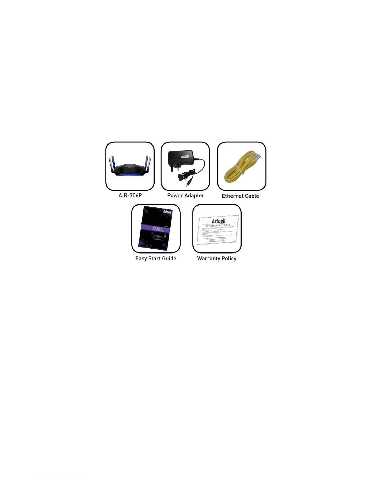
Package Contents
Package contents are listed below. For any missing items, please contact your
dealer immediately. Product contents vary for different models.
AIR-706P
Ethernet cable (Yellow)
12V 2.5A DC Power Adapter
Easy Start Guide
Warranty Policy
NOTE: You may also download the Quick Installation Guide and the User Manual by
visiting this link: http://www.aztech.com
Page 7
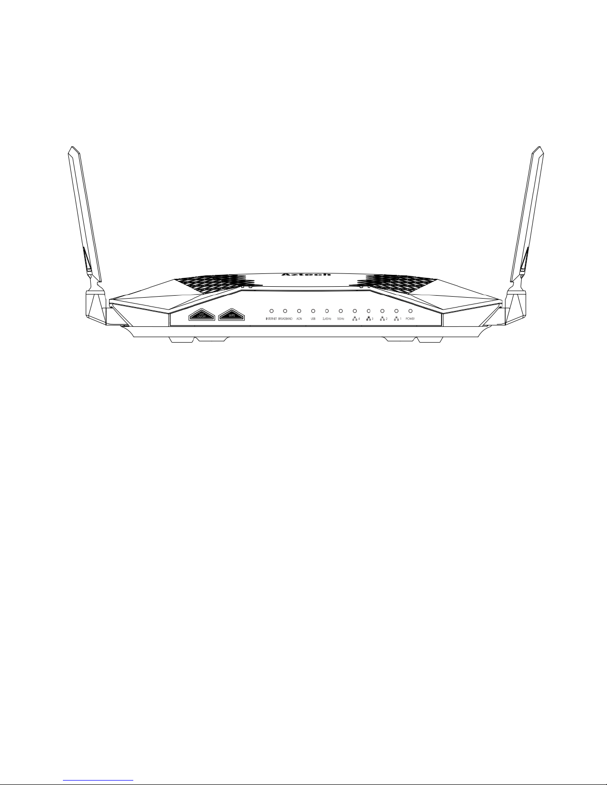
Device Design
Front Panel
LED
Status
Description
Power
Off
Green (Solid)
Red (Solid)
No power is supplied to the
device
Connected to a Power Supply
Error on the device
ETH LAN 1-4
Off
Green (Solid)
Green (Blinking)
No Ethernet connection
Connected to an Ethernet
device
Corresponding port is currently
transmitting / receiving data
5.0GHz/2.4GHz
Off
Green (Solid)
Green (Blinking)
There is no device connected
wirelessly
There is a device connected
wirelessly
Wireless interface is active
transmitting / receiving data.
USB Off
On
There is no USB device
connected to the
corresponding USB port.
A USB device connected to
the
corresponding USB port.
Page 8

AON
Green
Red (Solid)
Red (Blinking)
Mesh link is up and steady.
Mesh link between the router
and the node is weak.
Mesh link is down and not
available.
Broadband
Off
Green (Solid)
Green (Blinking)
There is no connectivity to the
ONT.
Connectivity to the ONT is
established.
WAN Ethernet interface is
connected.
Establishing ONT Signal.
Internet
Off
Green (Solid)
Red(Solid)
No internet
Internet interface is up
Authentication Failed
WPS Green (Fast Blinking)
Green (Slow Blinking)
Indicates Mesh Pairing
process.
Indicates WPS pairing
between router and device
Page 9

Back Panel
Physical Interface
Description
USB 1 and 2
USB 3.0 Ports for USB devices such as printers and
USB external hard drives
Ethernet 1 to 4
Connecting computers and other Ethernet
devices
Ethernet WAN
For WAN connection through an Ethernet cable
Reset
To reset the modem to the factory default
configuration
Power Input
12V 2.5A Adapter input
On/Off switch
Switch to on and off the router
Page 10
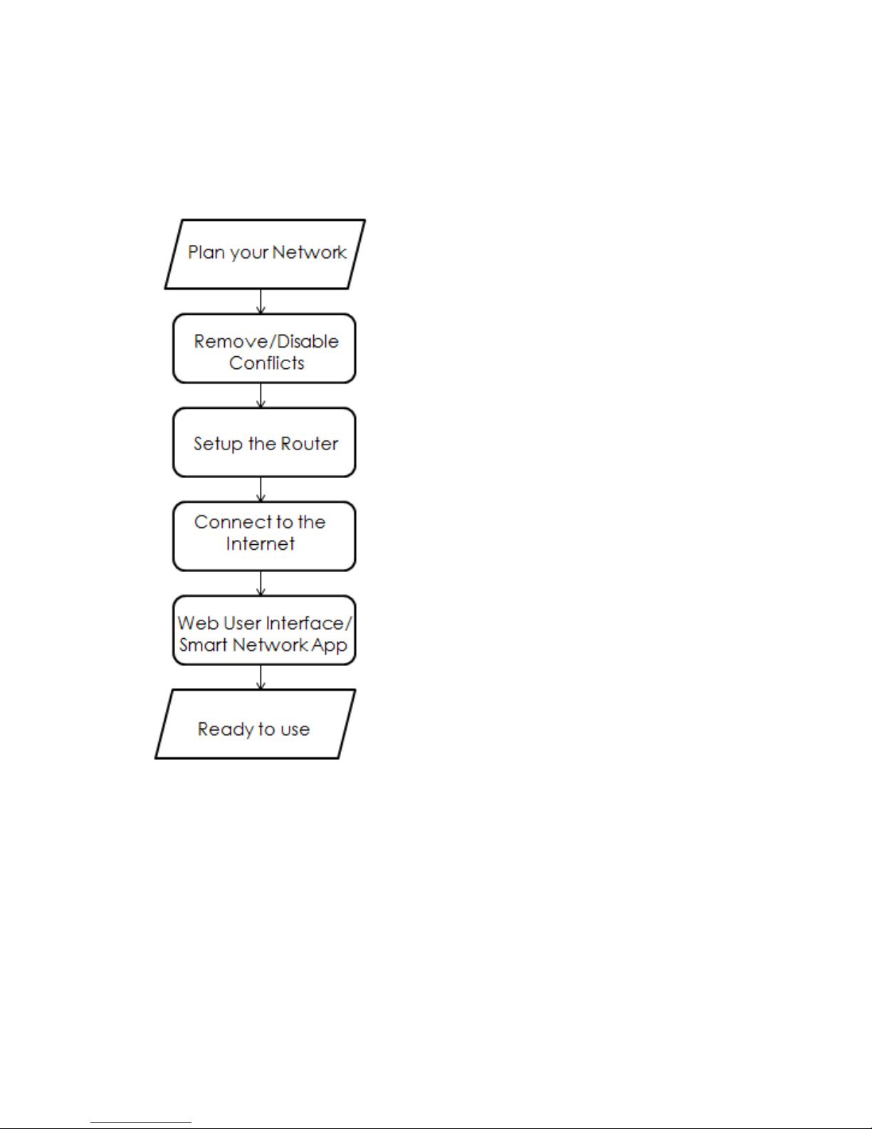
Getting Started
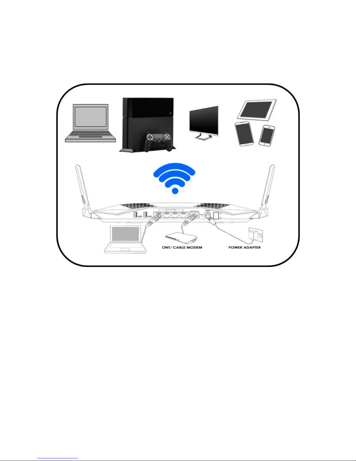
Setting up the device is easy. The diagram below provides an outline of the steps
needed in order to complete the installation. Brief descriptions appear beside each
step. Detailed instructions are provided in the subsequent pages.
You may see the suggested network setup.
You may need to remove or disable some
settings in your computer before proceeding
with the installation.
Connect the telephone cables, Ethernet cables
and power adapters.
Complete the Quick Setup Wizard to setup your
internet connection.
You may configure various router features
through the Web Interface or the Smart Network
App.
Page 11
Plan your Network
Before moving ahead to setup your network, it is a good idea to draw out a network
diagram to help identify your network devices and plan out how to connect these
devices.
Each port in the router can be used for different connections. For example:
Ethernet 1 – Set-top Box
Ethernet 2 – Game Console
Ethernet 3 – Desktop Computer
Ethernet 4 – Dad’s Computer
Ethernet WAN – ONT
To create a network diagram:
For wireless devices, identify the wireless devices you want to include in the
network
For wired devices, identify which router port you want to use for each device.
Page 12

Remove/ Disable Conflicts
To ensure that the router installation moves on smoothly, you need to remove or
disable conflicts that may interfere with the installation. Probable conflicts may
include:
Internet sharing applications
Proxy software
Security software
TCP/IP settings
Internet properties
Temporary Internet files
Internet Sharing, Proxy, and Security Applications
Internet sharing, proxy software, and firewall applications may interfere with the
router installation. These should be removed or disabled before starting the
installation. If you have any of the following or similar applications installed on your
computer, remove or disable them according to the manufacturer’s instructions.
If you have any of the following or similar applications installed on your computer,
remove or disable them according to the manufacturer’s instructions.
Internet Sharing
Applications
Proxy Software
Security Software
Microsoft Internet Sharing
Win Gate
Symantec
WinProxy
Zone Alarm
Configuring TCP/IP Settings
Check if your computer uses the default TCP/IP settings. Follow the steps below to
check the TCP/IP properties:
1. Select Start > Run. The Run dialog box would appear.
2. Enter control ncpa.cpl on the input box, and then click the OK button. This
would open the Network Connections window in your computer.
3. Right-click LAN and then select Properties. The Local Area Connection
Properties dialog box would appear.
4. Select Internet Protocol (TCP/IP) and then click Properties. The Internet
Protocol (TCP/IP) dialog box would appear.
Page 13

5. Select Obtain an IP address automatically.
6. Click the OK button to close the Internet Protocol (TCP/IP) dialog box.
7. Click the OK button to close the Local Area Connection Properties dialog
box.
Configuring Internet Properties
Follow the steps below to set the Internet Properties:
1. Select Start > Run. This opens the Run dialog box.
2. Enter control inetcpl.cpl and then click OK to open the Internet Properties
window.
3. Click on the Connections tab.
4. On the Dial-up and Virtual Private Network settings pane, select Never
dial a connection.
5. Click OK to close Internet Properties.
Removing Temporary Internet Files
Temporary Internet files are files from Web sites that are stored in your computer.
Delete these files to clean the cache and remove footprints left by the Web pages
you visited. Follow the steps below to remove temporary Internet files:
1. Select Start > Run to open the Run dialog box.
2. Enter control and then click the OK button to open the Control Panel.
3. Double-click Internet Options.
4. On the Internet Options window, in the Temporary Internet Files pane, click
Delete Cookies.
5. Click Delete Files.
6. Click OK to close Internet Properties.
Page 14
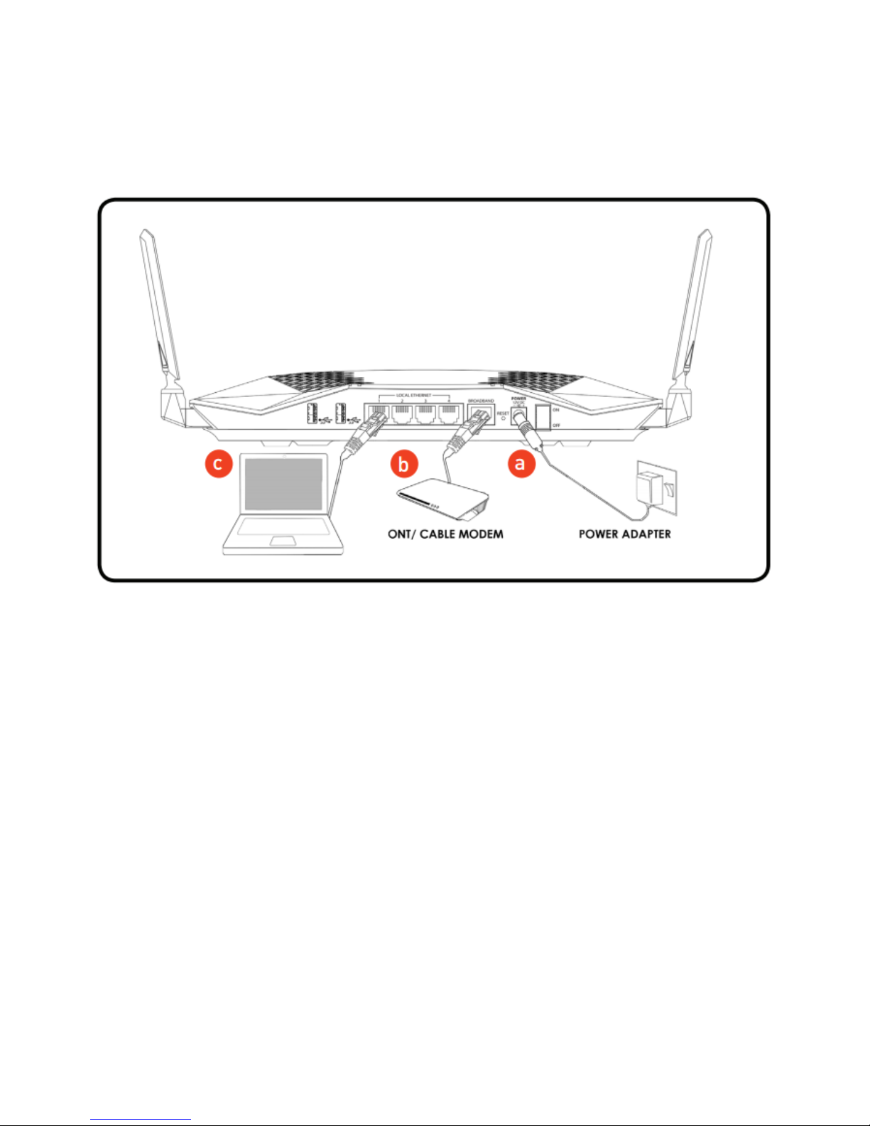
Setup the Device
When installing the router, find an area near the ONT and near an electrical outlet
for the router.
a. Power ON your AIR-706P by connecting and plugging its power adapter to a
power outlet.
b. Connect your ONT*/Cable Modem to the AIR-706P’s Broadband port using
an Ethernet cable.
c. Connect PC/Laptop to the router through local Ethernet or wireless.
NOTE: The POWER, BROADBAND, 2.4GHz and 5.0Ghz LEDs should now be
GREEN. If an Ethernet device is connected, its corresponding Ethernet LED
would be in GREEN. The Ethernet LED will also be blinking if there is activity on
the corresponding port.
Page 15
The Web User Interface
The Web User interface allows you to configure your router’s features.
NOTE: If you are logging in the Web User Interface for the first time, you will be
directed to the Quick Setup Wizard
Accessing the Web User Interface
To access your AIR-706P’s Web User Interface:
1. Launch any web browser (e.g. Internet Explorer, Google Chrome).
2. Type-in 192.168.1.254 on the address bar and then press Enter. When you
first access the Web User Interface, you will automatically be redirected to
the Basic Mode of the AIR-706P User Interface.
Page 16
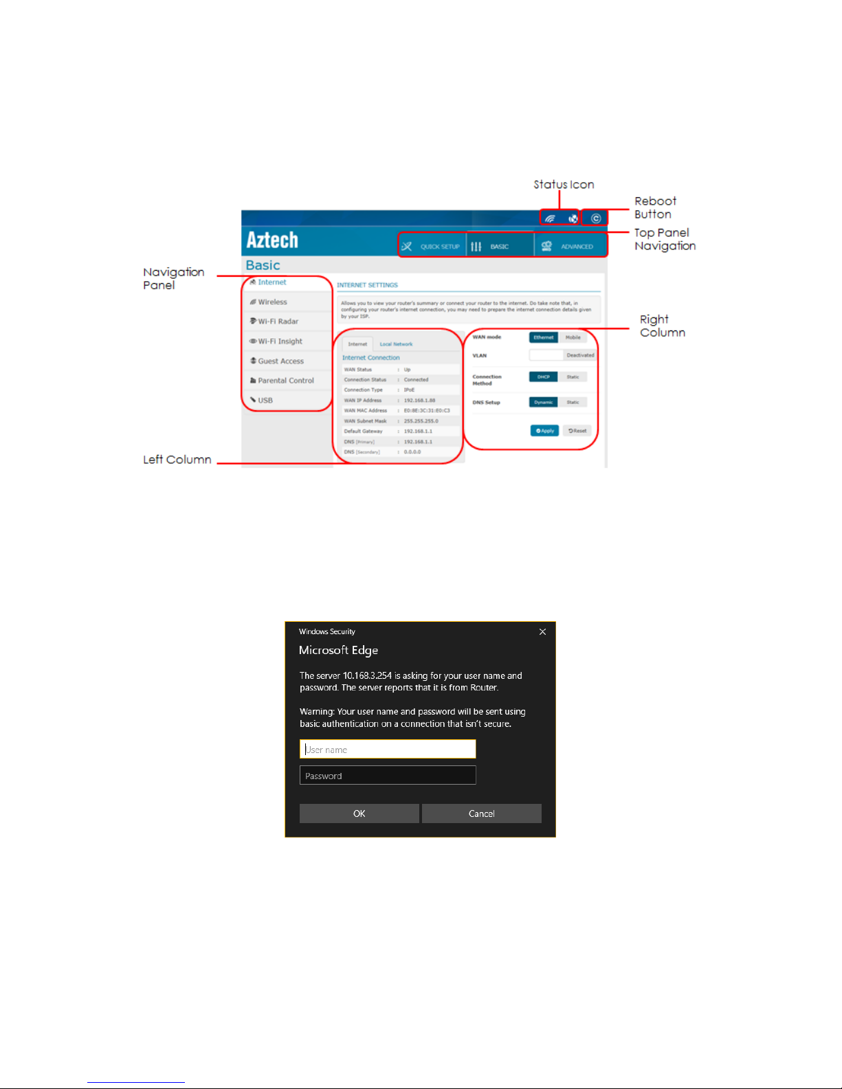
3. If you have set a password after your first setup, you will be prompted to
key in the user name and password you set for your Web User Interface.
Web User Interface
The Web User Interface is subdivided into three (3) different categories:
Quick Setup Wizard
Basic
Advanced
Status Icons and Reboot button
The AIR-706P has a top panel which displays a representation of (1) the Wireless
status and (2) the Internet Status. A Reboot feature is also available in the top panel
for easier means of soft device reboot.
Wireless Status
Internet Status
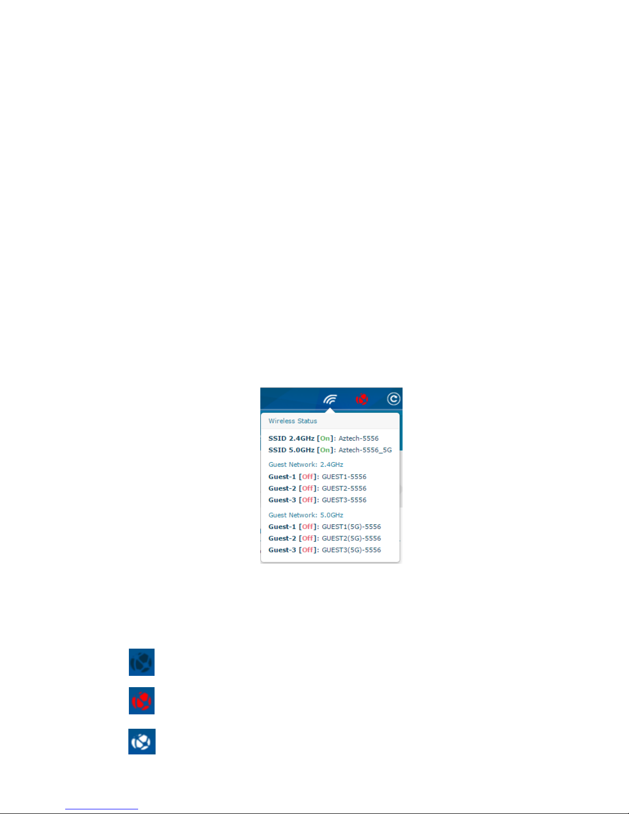
A. Wireless Status
The Wireless Status displays the different statuses that are currently enabled,
including the Guest network.
B. Internet Status
The internet status shows the different internet status. There 2 different statuses;
Configured or Unconfigured.
Internet Status Colour
Description
No WAN detected - Unconfigured
WAN detected - Unconfigured
Configured
Page 17
Quick Setup Wizard
The Quick Setup allows you to configure both the wireless properties of your router,
and the configuration of your fibre connection’s service provider. The Quick Setup
wizard has the following submenus:
Welcome
Change Password
Configure Internet
Modify Wireless
Summary
NOTE: It is highly recommended to go through the entire Quick Setup Wizard.
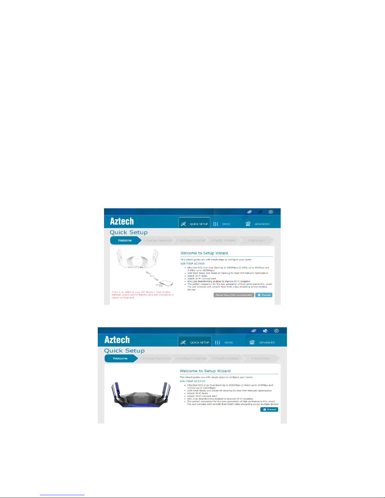
A. Welcome
This is the default page of the Quick Setup menu. It displays the main features and
product specifications of the AIR-706P.
Welcome page when WAN is not detected.
Welcome page when WAN is detected.
Page 18
In the Welcome page, you may either click Manual Setup (when WAN is not
detected or if WAN cable is not plugged in) or Proceed when WAN cable is plugged
in.
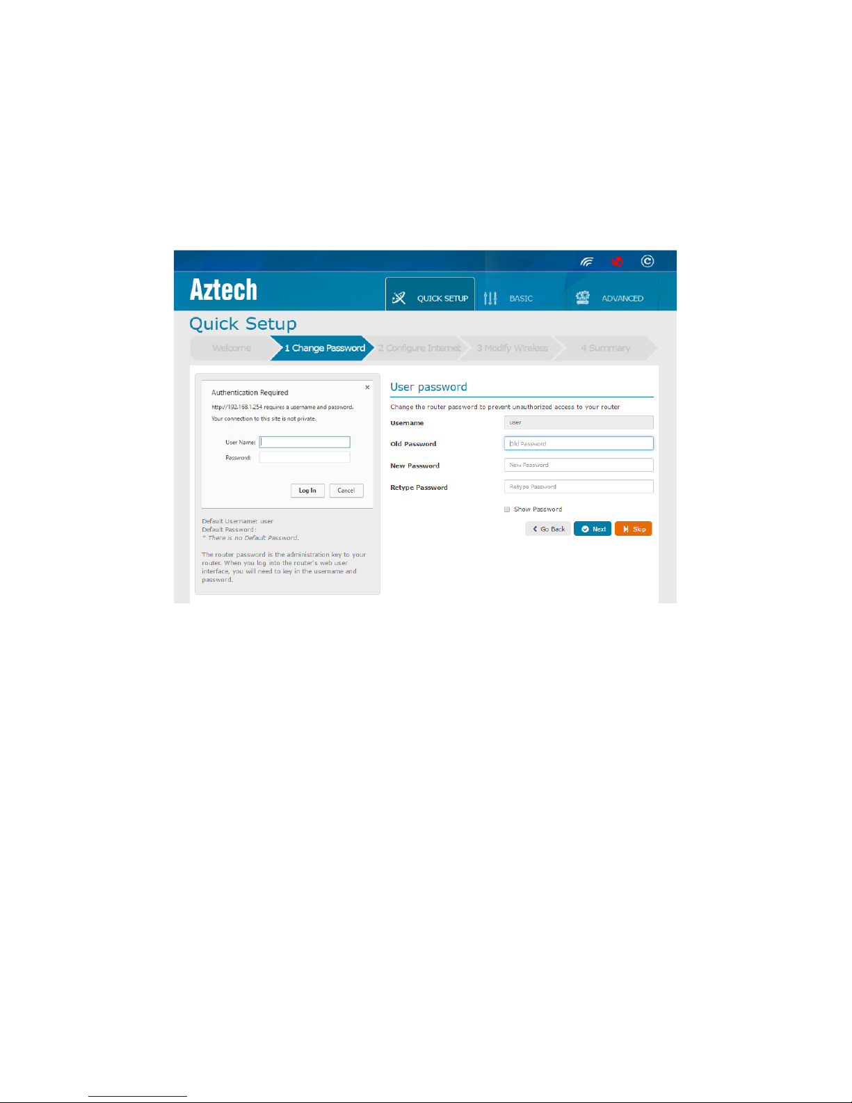
B. Change Password
Allows you to give a new password to access your Web User Interface or the Smart
Network App. By default, there is no password set to access the Web User Interface.
To configure your Web User Interface password;
NOTE: Leave the Old Password field blank
1. Enter a new password in the New Password field
2. Retype the same password entered in the New Password field
3. Click Next
C. Configure Internet
Allows you to configure your internet to the Internet Service Provider (ISP) profile of
your network. For Singapore Fibre Residents, there are 4 profiles to choose from;
Others
M1
Singtel
Starhub
The profile shown by default is Others. You may select the Profile according to your
ISP. In Others, you may configure the WAN mode, Connection Type, VLAN,
Page 19
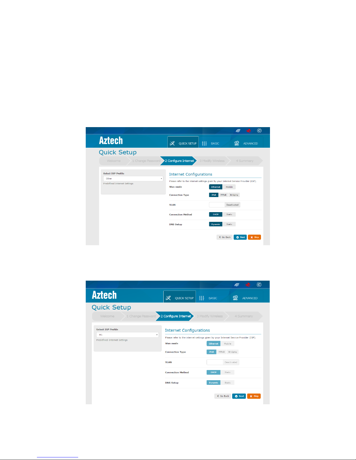
Connection Method and DNS Setup to desired. For M1, Singtel and Starhub, their
configurations are pre-set and no changes can be made at this point.
To configure the Internet;
NOTE: Clicking Skip will not complete your setup
1. Choose an ISP profile
2. Click Next
Others Profile Internet Configurations
There is no pre-set configuration in Others. You may set your desired configuration
accordingly.
M1 Profile Internet Configurations
In M1 Profile, WAN mode is set to Ethernet, Connection type is IPoE,VLAN is
deactivated, Connection method is DHCP and DNS setup is Dynamic.
Page 20
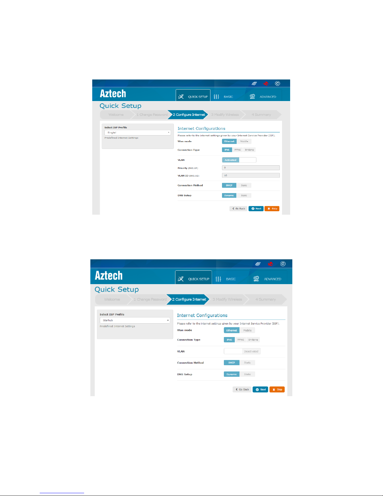
Singtel Profile Internet Configurations
When Singtel profile is selected, VLAN is Activated and Priority and VLAN ID is set to 0
and 10 respectively. WAN mode is Ethernet, Connection type is IPoE, Connection
method is DHCP and DNS setup is Dynamic.
Starhub Profile Internet Configurations
In Starhub Profile, WAN mode is set to Ethernet, Connection type is IPoE,VLAN is
deactivated, Connection method is DHCP and DNS setup is Dynamic.
Page 21
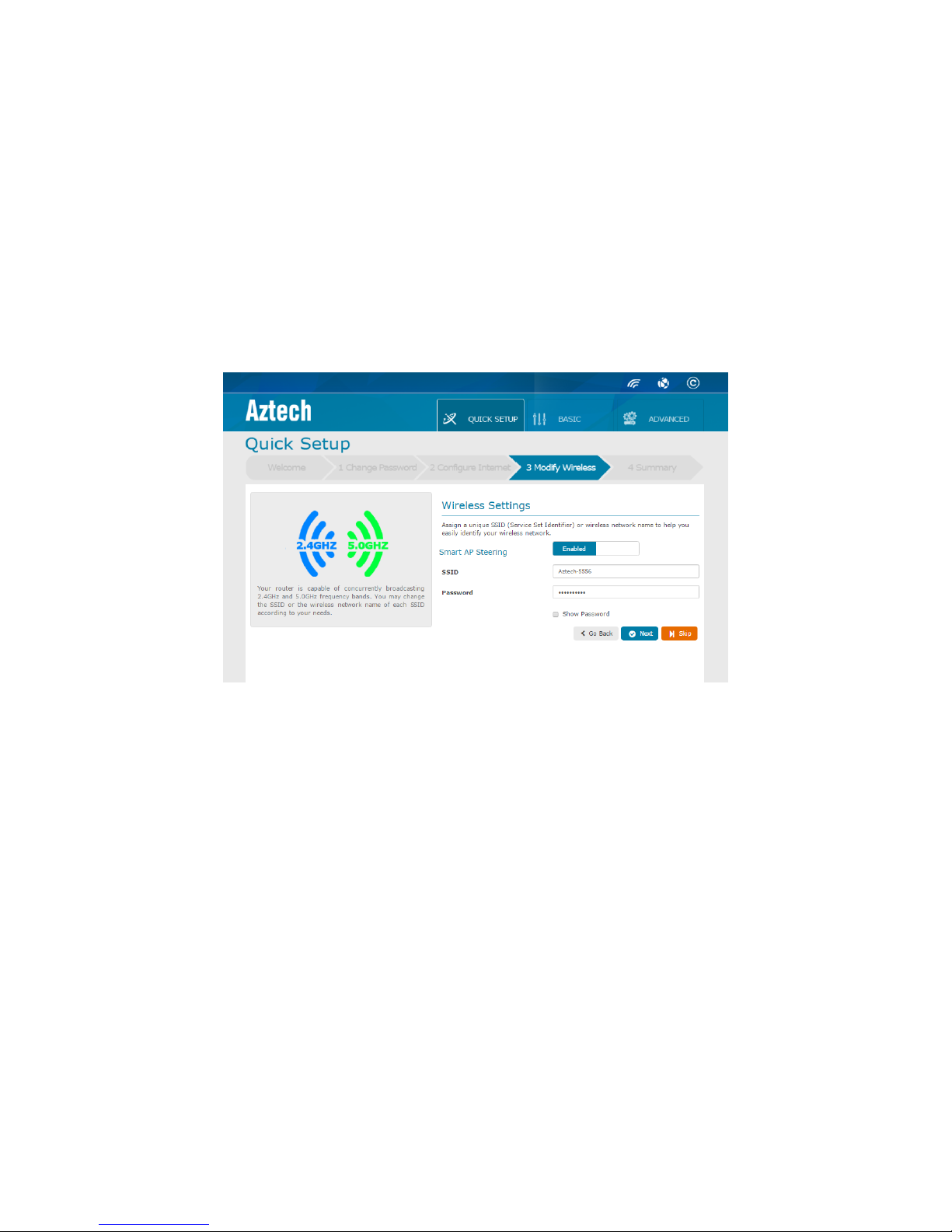
D. Modify Wireless
Allows you to modify your Wireless Network Name/Service Set Identifier (SSID) and
Network Key (Password). In this page, you can also set to Enable or Disable the
Smart AP Steering. If you do not wish to make any modify your wireless settings, you
may click Skip. By default, Smart AP Steering is Enabled.
Smart AP Steering - Enabled
When Smart AP Steering is Enabled, you will only see one SSID in the Wi-Fi list of your
device. This feature enforces your dual band wireless devices to automatically
connect to the AIR-706P’s 5.0GHz frequency band or to roam to 2.4GHz frequency
band when needed.
To configure the Wireless Settings when Smart AP Steering is Enabled;
1. Click on Show Password (This is to uncensored the password in the Password
field)
2. You may designate an SSID or a Wireless Network Name for your wireless
network or use the default SSID of your AIR-706P.
3. You may designate a Network Password for your wireless network.
4. Click Next
NOTE: The Default SSID and Network key for your AIR-706P can be seen on the
device label sticker of your device.
Page 22
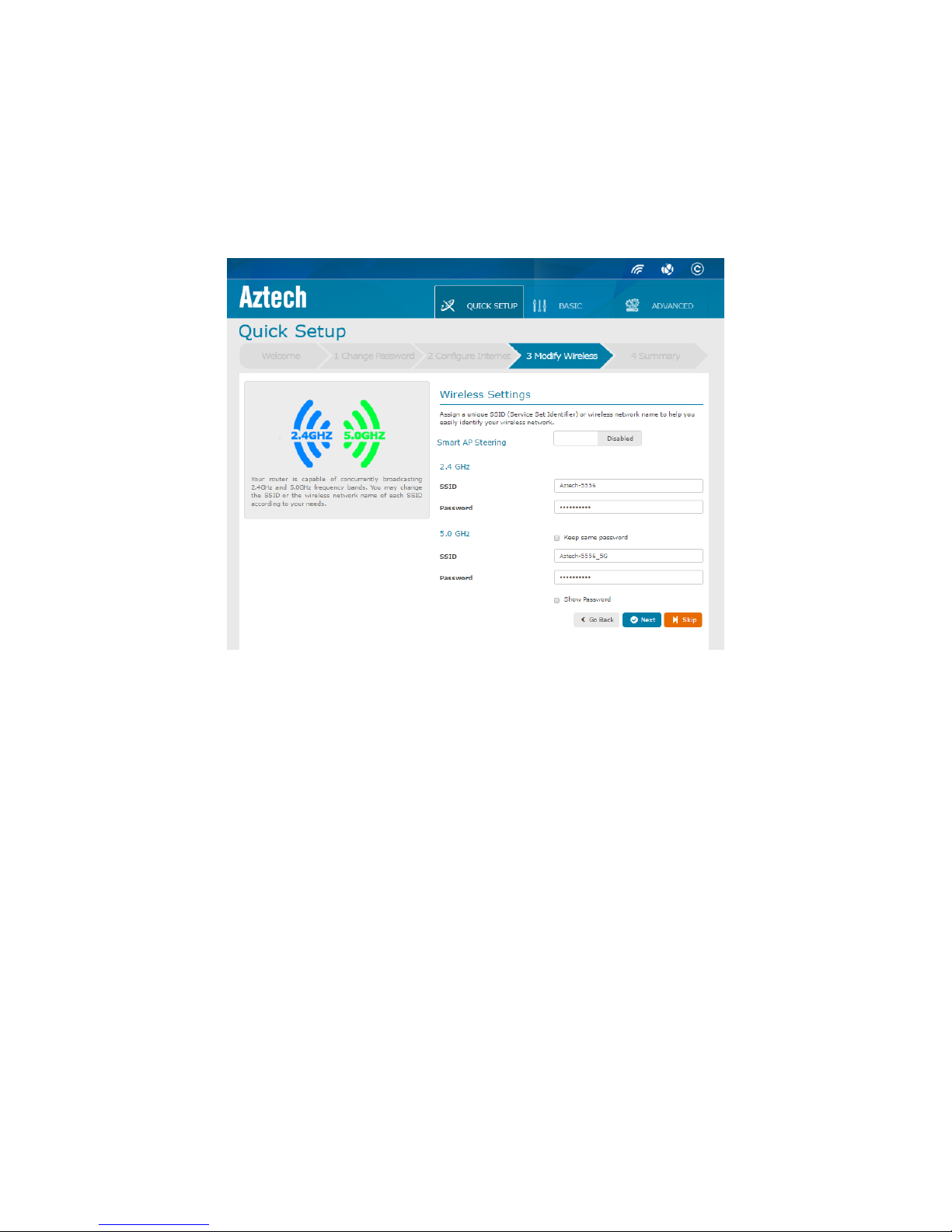
Smart AP Steering – Disabled
AIR-706P is capable to concurrently broadcast 2.4GHz and 5.0GHz frequency bands.
This can be done so by disabling the Smart AP. When Disabled, you may choose to
set the SSID for both the AIR-706P’s 2.4GHz and 5.0GHz. The passwords for the SSID
network can be kept the same when you click on the Keep same password
checkbox.
To configure the Wireless Settings when Smart AP Steering is Disabled;
1. Click on the Smart AP Steering slider button
2. You may choose to set the 2.4GHz SSID to your designated network name.
3. You may set the network password to your designated password
4. If Keep same password is ticked, the password for the 2.4GHz and 5.0GHz
frequency bands will be the same.
5. Change the 5.0GHz SSID to your desired network name.
6. If Keep same password is unticked, the password for the 2.4GHz and 5.0GHz
frequency bands can be set differently.
7. You may set your password to your designated password
8. Click Next
Page 23
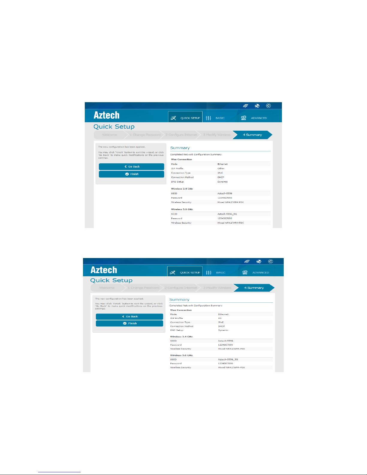
E. Summary
Allows you to view the summary of the settings done in Quick Setup Wizard. If there
are any settings not in order, you may click on the Go Back button to change the
settings in the previous pages. Once everything is set accordingly, ensure to click on
the Finish Button. You will be re-directed to the Basic page after clicking Finish.
Summary page when Other Profile is selected without changing the configurations.
Summary page when M1 profile is selected.
Page 24
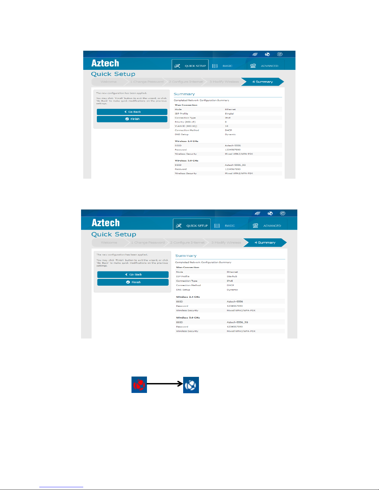
Summary page when Singtel profile is selected.
Summary page when Starhub profile is selected.
Once the Internet is all set up, the Internet Status icon turns from Red to White.
Page 25
Basic
Allows you to configure the basic properties of your AIR-706P. This includes the basic
wireless network properties, basic setting configurations such as parental control and
other features. There are 7 different tabs in the left side panel of the basic page.
These tabs include the following;
Internet
Wireless
Wi-Fi Radar
Wi-Fi Insight
Guest Access
Parental Control
USB
Torrent (only available when Torrent is Enabled)
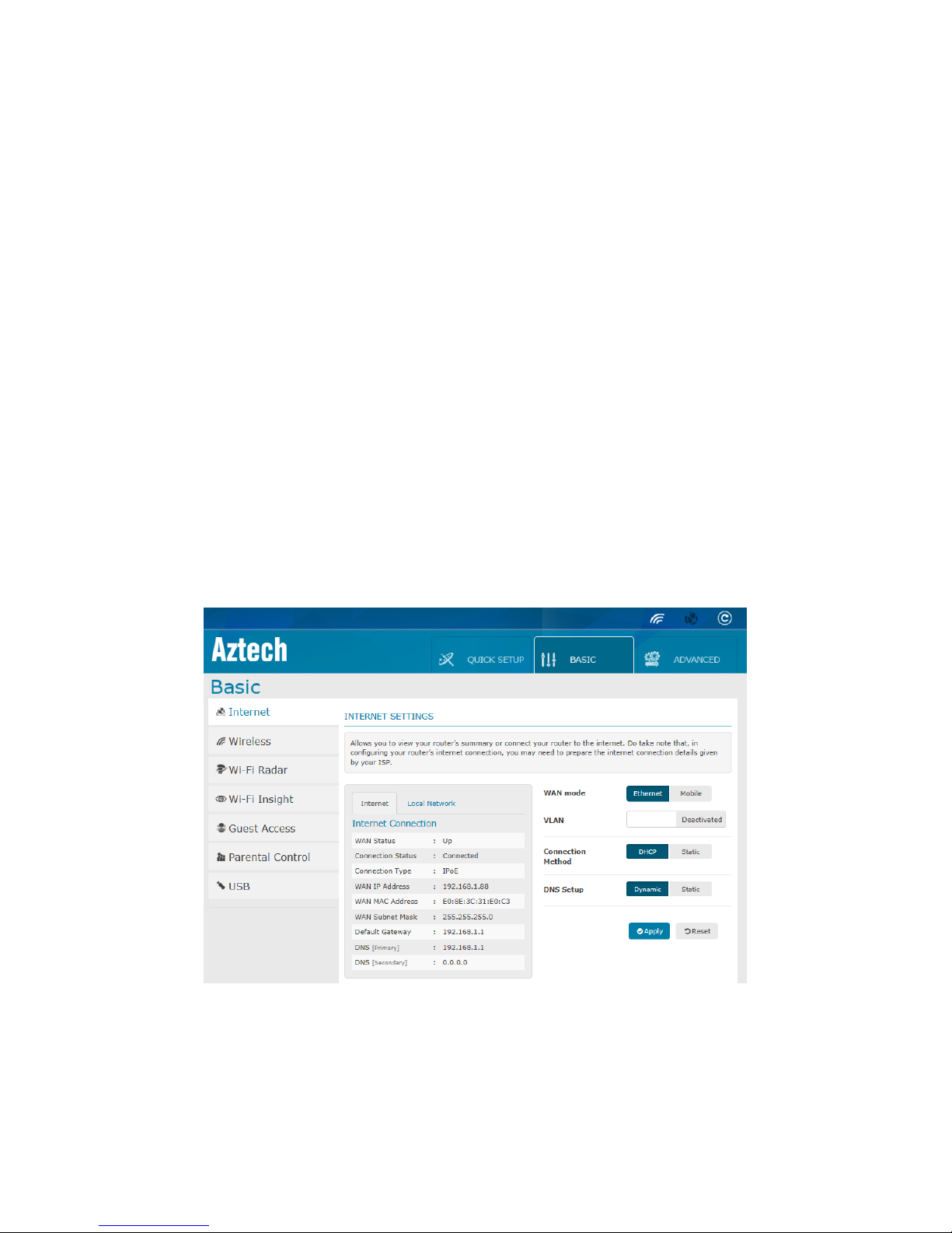
A. Internet
The default page of the Basic page. It allows you to view the internet settings of AIR706P. In this page, you will be able view the Internet Connection and Local Network
summary. You may also change the settings of your WAN mode, VLAN, Priority, VLAN
ID, Connection Method and DNS Setup.
Page 26
Left Column of Internet Settings
The left column of Internet Settings page displays the summary of the Internet and
Local Network (Local Area Network - LAN) connection. This can be viewed
accordingly by clicking on the respective tabs.
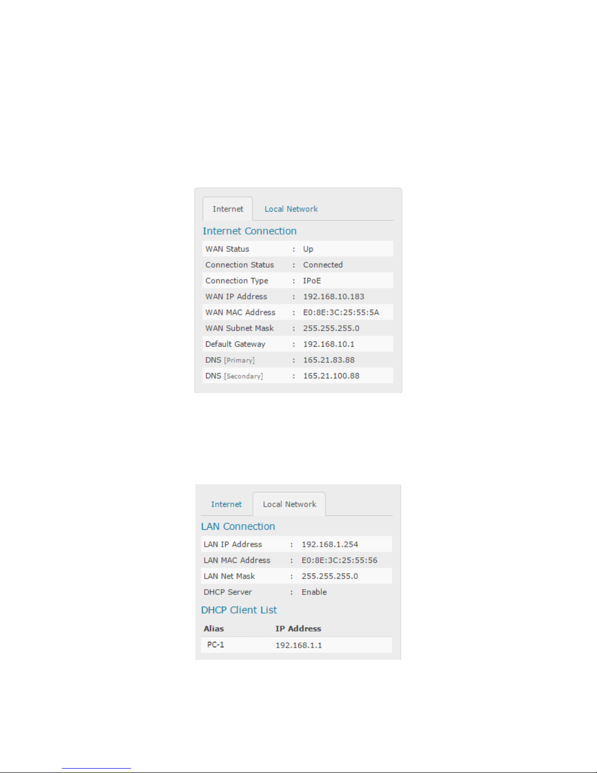
Internet Connection Summary
The summary shown in the Internet Connection shows the Wireless Area Network
(WAN) summary inclusive of the WAN IP Address and WAN MAC Address.
LAN Connection Summary
The summary shown in the LAN Connection shows the LAN summary inclusive of the
LAN IP Address and LAN MAC Address. In the LAN Connection, the Dynamic Host
Configuration Protocol (DHCP) Client List is also displayed here. DHCP Client refers to
the client connected to the AIR-706P.
Page 27
Right column of the Internet Settings
In the right column of the Internet Settings allows you to configure the WAN mode,
VLAN, Priority, VLAN ID, Connection Method and DNS Setup. For Singapore Fibre
Residents, when M1 or Starhub are set as your ISP profile, the Right column will be
shown as below.
NOTE: You may choose not to change the configuration settings in this section.
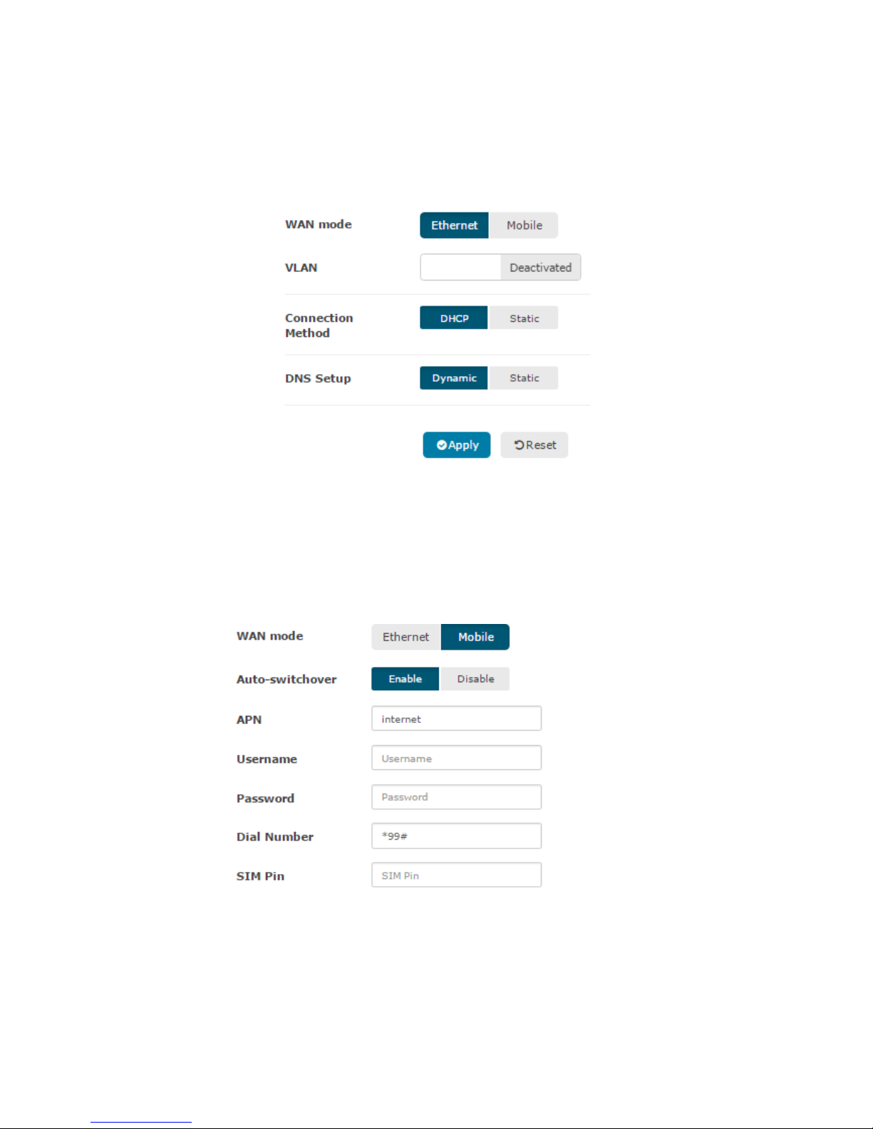
To configure the settings in the Right column;
1. Choose the WAN mode. By default, the WAN mode is Ethernet.
When WAN mode is Mobile, set the following;
a. Set the Auto-switchover
b. Set the APN
c. Set the Username
d. Set the Password
e. Set the Dial Number
f. Set the SIM Pin
Page 28
The VLAN and the Connection Method will not be part of the settings
when WAN mode is Mobile
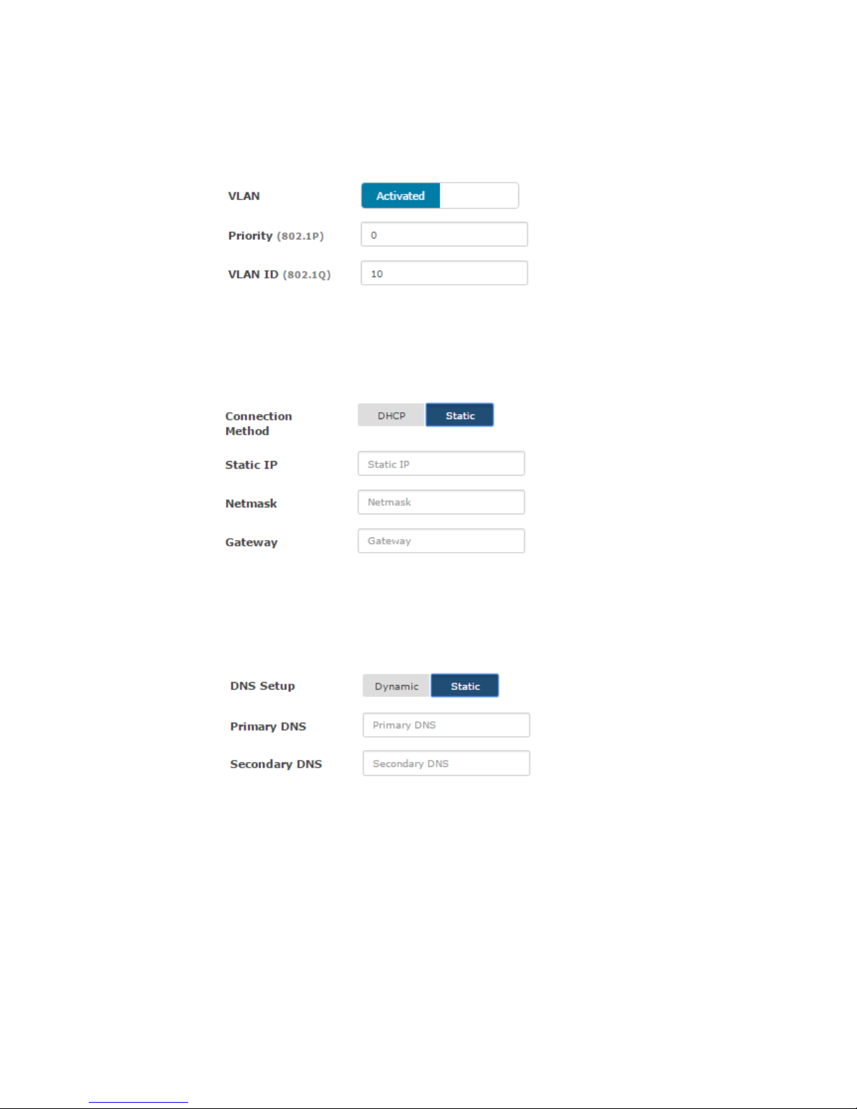
2. Choose a setting for the VLAN.
When VLAN is Activated, set the following;
a. Set the Priority
b. Set the VLAN ID
3. Choose the Connection Method. By default, Connection Method is Dynamic
When Connection Method is set to Static, set the following;
a. Set the WAN Static IP
b. Set the Netmask
c. Set the Gateway IP
4. Choose the DNS Setup. By default, DNS Setup is Dynamic.
When DNS Setup is set to Static, set the following;
a. Set the Primary DNS
b. Set the Secondary DNS
5. Click Apply
6. To Reset to original settings, click Reset
Page 29
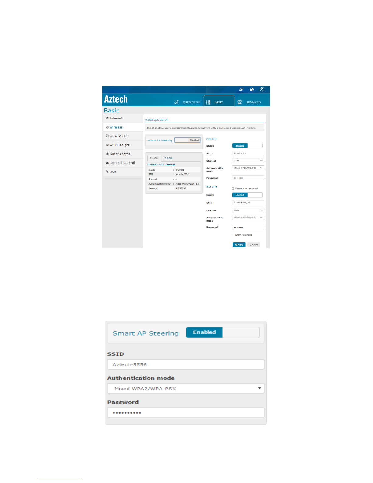
B. Wireless
Allows you to configure your router’s basic wireless features. The Wireless also allows
you to Enable/Disable the Smart AP Steering and modify the Authentication Mode
and set the Network Key. It also shows the summarised Wi-Fi settings of your router.
Left Column of the Wireless Setup
Allows you to Enable or Disable the Smart AP Steering and to configure the SSID,
Authentication mode and Password when Smart AP Steering is Enabled. When Smart
AP Steering is Enabled, only the Channel and setting the wireless 2.4GHz and 5.0GHz
to Enable/Disable can be configure in the Right column of the wireless setup.
Page 30

To configure the Wireless Settings in the left column when Smart AP Steering is
Enabled;
1. Ensure that Smart AP Steering is Enabled
2. You may designate a new SSID or a Wireless Network Name for your wireless
network or use the same SSID of your AIR-706P you set during Quick Setup.
3. Select an Authentication mode on the drop down list. It is highly suggested to
use Mixed WPA2/WPA-PSK as its authentication.
4. You may designate a new Network Password for your wireless network or use
the same password of your AIR-706P you set during Quick Setup.
NOTE: Step 2 and Step 4 is applicable if you wish to change the SSID and password
from the SSID and password you set during Quick Setup.
Page 31

Summary of 2.4GHz and 5GHz settings
The existing settings summary in the Right column is displayed in the left column
under Current WiFi Settings. To view either 2.4Ghz or 5.0GHz, click on either the
2.4GHz and 5.0GHz tab respectively.
Right column of the Wireless Setup
Allows you to configure the SSID, Authentication mode, Password and Channel
when Smart AP Steering is Disabled. When Smart AP Steering is Enabled by default,
only the Channel and setting the wireless 2.4GHz and 5.0GHz to Enable/Disable can
be configure in the Right column of the wireless setup.
Page 32

When Smart AP Steering is Disabled, the Right column will display as below.
To configure the 2.4GHz of the Wireless Setup;
1. You may set the 2.4GHz frequency band to Enabled/Disabled. Once
Disabled, the 2.4GHz SSID will not be visible.
2. You may designate a new SSID or a Wireless Network Name for your 2.4GHz
wireless network.
3. Select a Channel. By default, the channel is set to Auto.
NOTE: It is highly recommended to select Auto mode as your router’s Channel
setting. This enables your router to continuously use the least congested Wi-Fi
channel at all times.
4. Select an Authentication mode on the drop down list. It is highly suggested to
use Mixed WPA2/WPA-PSK as its authentication.
5. You may designate a new Network Password for your 2.4GHz wireless network
6. Click Apply
7. To reset to original settings, click Reset
Page 33

To configure the 5.0GHz of the Wireless Setup;
1. You may set the 5.0GHz frequency band to Enabled/Disabled. Once
Disabled, the 5.0GHz SSID will not be visible
2. You may designate a new SSID or a Wireless Network Name for your 5.0GHz
wireless network.
3. Select a Channel. By default, the channel is set to Auto.
NOTE: It is highly recommended to select Auto mode as your router’s Channel
setting. This enables your router to continuously use the least congested Wi-Fi
channel at all times.
4. Select an Authentication mode on the drop down list. It is highly suggested to
use Mixed WPA2/WPA-PSK as its authentication.
5. You may designate a new Network Password for your 5.0GHz wireless network
6. Click Apply
7. To Reset to original settings, click Reset
NOTE: When the Smart AP Steering is Enabled, only the Channel can be configured
in the Right column. Follow Step 3 to configure your Channel.
Page 34

C. WiFi Radar
Allows you to see the devices connected to the AIR-706P’s 2.4GHz and 5.0GHz Wi-Fi
Network. There are two tabs in the Wi-Fi Radar;
Wi-Fi Radar
Wi-Fi Table
Wi-Fi Radar
In this page, it enables you to see the connected devices and to know their signal
strength.
Frequency Band
Icon
Signal Level
5.0GHz
Fair
Good
Excellent
2.4GHz
Fair
Good
Excellent
Page 35

You may move your mouse cursor over to the icon and it will show more information
about the device such as its IP address, MAC address and signal strength value
(RSSI).
Wi-Fi Table
In the Wi-Table, you will be able to see the connected devices your router’s 2.4GHz
and 5.0GHz frequency band. In this table, it displays the signal strength(RSSI), MAC
Address and IP Address of your wireless devices, as well as the designated name of
the device.
D. Wi-Fi Insight
Allows you to quickly scan, analyze and monitor the wireless networks around you. There
are 3 tabs in Wi-Fi Insight;
Site Survey
Channel Capacity
Metric
By default, Site Survey is displayed.
Site Survey
Allows you to see the Access Points (APs) around you for 2.4GHz and 5.0GHz bands.
A filter is also provided to allow you to filter the frequency band, channel and
bandwidth you wish to view. A scrollable table is also included to view the channels,
network names of the scanned APs, MAC Address and other information about the
network. By default, it will show the APs in 2.4GHz frequency band, all the channels
and all the 2.4GHz bandwidths.
Page 36

To filter the frequency, channel and bandwidth;
1. Select the frequency from the 2.4GHz/5.0GHz dropdown list
2. Select the channel from the channel dropdown list
3. Select the bandwidth from the bandwidth dropdown list
4. Click Scan
Page 37

Channel Capacity
Allows you to view the Channel Statistics inclusive of the WiFi and Non-WiFi
interferences as well as the available bandwidth for each channel. It also displays
the current channel, current channel bandwidth and available capacity your router
has. You can filter to view 2.4GHz and 5.0GHz frequency bands’ Channel Statistics
respectively by choosing from the dropdown list.
Bar graph representations of the Adjacent Channel, Interference and Channel
Capacity can be found in this page. As you scroll down the page, you will also see
the bar graph for Interference and Adjacent Channel.
Page 38

Metric
Allows you to view most of the counters like Aggregated Mac Protocol Data Unit
(AMPDU), glitch, chanim (also can be referred to transferred packet) and Packet
Queue Statistics. This page can help you in your troubleshooting. A live graph for
different counters is displayed on this page to keep track of the counter statistics.
Page 39

E. Guest Access
Allows you to have two separate Wi-Fi access points — a primary, secure one for
yourself and an isolated one for your guests. Guests who join the guest Wi-Fi network
are given Internet access, but they will not be able to access your primary network.
To configure the Guest Network;
1. Choose the Wireless Type; 2.4GHz or 5Ghz
2. Select the Guest Index
3. Set a SSID for the Guest Network. Alternatively, you may wish to keep the SSID
unchanged and remains as the default SSID for the Guest Network.
4. Enable the SSID by setting the Enable to Enabled
5. Select an Authentication mode on the drop down list. It is highly suggested to
use Mixed WPA2/WPA-PSK as its authentication.
6. You may designate a new Network Password for your 5.0GHz wireless network
7. Click Apply
F. Parental Control
Allows you to control the Internet access time for a user’s client in any day and time
of the week. You can also set a URL filter to block out internet pages.
Access Time Restriction
Page 40

To configure your router’s Access Time Restriction;
1. Click Add
2. Your page will be redirected to this page:
3. Assign a Rule Name
4. Select the MAC Address of the device you wish to restrict.
1. My Device MAC Address refers to the device you are using to access
the Web Interface
2. Other MAC Address refers to the other devices connected to the
network. Use the dropdown list to view the list of connected devices
5. Select the day(s) of the week you wish to restrict the client
6. Set the Start Blocking Time
7. Set the End Blocking Time
8. Click Apply
NOTE: To find out the MAC address of a Windows based PC, launch command
prompt and type ipconfig/all
URL Filter
By default, none of the URL list type is selected. When Exclude is selected, this means
that any URL listed are blocked or not accessible by any clients. When Include is
selected, this means that any URL listed in the list is the only URL that can be
accessed by the clients. Any URL not listed in the Include list is blocked.
NOTE: Only HTTP websites are supported
Page 41

To add the a URL in the Exclude or Include list;
1. Select Exclude or Include by clicking on the Exclude or Include radio button.
2. Click Add. You will be redirected to this page:
3. Key in the complete URL of the web page in the URL Address field. Eg
http://webpagename.com
4. Key in the Port Number. By default, port 80 is used. You may choose to leave
the Port Number field blank and the default port will be assigned.
G. USB
AIR-706P provides two 3.0 USB ports for connecting your USB devices and USB printer
to allow you to share files and printer with clients in your network. You may also
configure the Torrent Setup in this section.
Page 42

Manage USB Device
Volume Name refers to the index assigned to your USB device. The first USB device
you plug in will take after the Volume name, disk1_1. The second USB device you
plug in will be disk2_2. In this page, the basic information about your USB is
displayed.
NOTE: AIR-706P works with most USB thumb drives and USB hard disk (up to 2TB) and
supports FAT 32 and NTFS read-write access.
Page 43

Safely Ejecting your USB
It is important that you safely remove your USB device from the router by clicking on
the Eject button. Failing to do so can result to incorrect removal of USB and can
cause your data to be corrupted.
To safely eject your USB;
1. Go to USB under the Basic Page
2. Click the Eject for the USB you wish to eject
3. When the USB is ejected successfully, it will show No USB device attached
NOTE: If your USB device is not ejected properly, when the same USB device is plug, it
can take after a new volume name.
Torrent Setup
AIR-706P has a built-in torrent client to manage your torrent files without the need of
an additional application for torrent. By default, Torrent Client is Disabled. Once
Enabled, a Torrent tab will be added to the Navigation Panel. You can configure
your torrent setup in this page.
To configure the Torrent Setup
1. Set the Upload Bandwidth.
2. Set the Download Bandwidth.
3. Set the Storage List by selecting in the dropdown list.
NOTE: By default, the upload and download bandwidth is set to 1000kbps or 1Mbps
to reach highest performance when using Torrent Client.
Page 44

H. Torrent
Allows you to upload and download torrent files such as videos, audio and picture
using the built in torrent client provided.
Uploading Torrent File
To upload a torrent file for downloading;
1. Click on the folder
2. You can upload your torrent file from your PC by clicking Choose File.
Alternatively, you may provide the URL of the torrent file.
3. Assign the Destination Folder in your USB device. A Downloads folder will be
created to serve as the Destination Folder.
4. Tick the Start when added checkbox.
5. Click Upload.
After clicking upload, your torrent file will begin downloading.
Page 45

Pausing and Resuming your download
There are two sets of pause and resume buttons for you to control your torrent.
To pause and resume one torrent download;
1. Click on file
2. Click on the pause icon found in the middle of the button panel when
you wish to pause your download
3. Click on the single green arrow when you wish to resume your paused
download
Page 46

To pause and resume all torrent downloads;
1. Click on the pause icon found on the right of the button panel when
you wish to pause all torrent downloads
2. Click on the resume icon found on the right of the button panel when
you wish to resume all paused torrent downloads
To stop your torrent download;
1. Click on the file
2. Click the stop button found beside the folder button
Toggle Inspector
An information icon can be found on the Torrent Client. This is the Toggle Inspector
where it will give more information about your torrent download. When selected, the
page also displays the Peers, Trackers and Files that will be downloaded
Page 47

Advanced
Some of the features included in the Advanced allows you to; (1) access the
Advanced Setup of the features of your AIR-706P (2) view the router’s information
and connected devices (3) configure the router’s security settings (4) configure
your advanced wireless settings, (5) view the router’s diagnostics and (6)
manage your router. The Advance Setup menu has the following features:
Device Info
Statistics
Advanced Setup
Security
Wireless
Diagnostics
Management
Page 48

A. Device Info
Allows you to see the information about your router, its uptime and also the
connected devices. This page have two sub menus; (1) Device Info Summary and
(2) DHCP Client.
1. Device Info Summary
Displays a brief summary of your AIR-706P’s device properties such as its model, the
current firmware version loaded into your router, the device’s unique MAC address,
the system up time, and other similar properties such as your LAN IPv4 Address and
default gateway.
2. DHCP Client
Displays the dynamically assigned IP Addresses, each devices’ corresponding
hostname and MAC address, the type of connection (WLAN or LAN), and the lease
expiry time.
NOTE: When the client’s IP address expires, the router will renew the IP address of the
client.
Page 49

B. Statistics
Allows you to see the LAN statistics where it displays the current statistics of both the
received and transmitted packets of the LAN. A Reset Statistics button is provided to
reset the statistics displayed and you can use the scroll bar to display the transmitted
packet.
C. Advanced Setup
The Advanced Setup page allows you to (1) configure your LAN setup (2) set the
router mode (3) add routes and view the current routing table used, (4) configure
DMZ, Port Forwarding and Port Triggering applications, (5) enable your IPv6, print
server, DLNA (7) configure the QoS settings, (8) configure the port mapping features
of your router (9) Set the time and day of rebooting your router through the Auto
Reboot feature and other advanced features.
The Advanced Setup has the following sub menus;
LAN
Device Mode
IPv6 Autoconfig
UPnP
DNS Proxy
Print Server
DLNA
Auto Reboot
Multicast Precedence
Torrent Setup
NAT
Quality of Service
Router
DNS
IP Tunnel
Page 50

1. LAN
Allows you to configure the DSL Router IP Address and Subnet Mask for LAN
interface. You may also configure the DHCP server and Public IP Pass Through
settings of your router. This page also displays the DHCP Client list connected to the
modem/router.
Page 51

To configure the LAN settings;
1. Enter the preferred IP Address and corresponding subnet mask that you wish
to assign to your AIR-706P. NOTE: The IP Address to be specified in this area will
be the new default IP Address you would be using to access your AIR-706P
web user interface.
2. You may enable or disable IGMP Snooping and its required properties if it is
required in your network. It is highly suggested to enable this if you wish to filter
out multicast traffic in your network.
3. Select a radio button to choose between Standard and Blocking mode. By
default, it is set to Blocking mode.
4. Set you IGMP LAN to LAN Multicast to Enabled or Disabled. By default, this is
Disabled. NOTE: LAN to LAN Multicast is enabled until the first WAN service is
connected, regardless of this setting.
5. If you wish to implement Static IP addressing, tick Disable DHCP
Server. NOTE: By default, DHCP Server is enabled.
6. For Dynamic IP Addressing (DHCP) tick Enable and enter the
Start IP and End IP Address, the correct subnet mask, and the
lease time (in hours) for all connected devices.
7. If you wish to indicate a second IP address for your router, tick the Configure
the second IP Address and Subnet Mask for LAN
interface and define the values needed in the fields. This may come in handy
when you are troubleshooting your router.
8. Click Apply/Save to apply the changes. NOTE: The router will reboot after
defining the preferred IP address.
Page 52

(Optional) - Static IP Lease List. Displays the statically assigned IP addresses in the
network, each device’s MAC Address and assigned IP Address can be seen in
this table. It also allows you to remove reserved IP addresses as well.
To reserve a device:
1. Click Add Entries.
2. Enter the MAC Address of the device that you wish to reserve.
3. Enter the IP Address to be assigned to the device.
4. Click Apply/Save to reserve the device.
To remove reserved devices:
1. On the Static IP Lease List table tick the Remove checkbox that
corresponds to the MAC Address of the device that you wish to remove.
2. Click Remove to remove the device.
Page 53

2. Device Mode
Allows you to set your AIR-706P as a Router or Access Point.
Router Mode
In Router mode, the AIR-706P connects to the Internet and shares the wireless
network to LAN clients or devices. Features such as Firewall, NAT features and DHCP
server are enabled.
Access Point (AP) Mode
In Access Point (AP) mode, the router connects to a wireless router through an
Ethernet cable to extend the wireless signal coverage to other network clients.
Features such as Firewall, NAT functions and DHCP server are disabled.
To configure the AIR-706P mode;
1. Choose and Select the Connection Type, either Router or Access Point.
2. Click Apply/Save to apply the changes.
Page 54

3. IPv6 Auto LAN Configuration
Allows you to specify a static LAN IPv6 address and its prefix length, enable/disable
the IPV6 properties of your router such as DHCPv6 Server and MLD Snooping. Do
take note that you have to enable the property first before you can enter or
configure the parameters for the said properties
4. UPnP
Allows you to enable the Universal Plug and Play feature of your AIR-706P. The UPnP
feature allows an easier means of device discovery in your network (e.g. network
printer etc.). This is Enabled by default.
Page 55

5. DNS Proxy
Allows you to enable and configure the DNS proxy features of your AIR-706P such as
the Broadband router’s preferred hostname, and the domain name of the LAN
network that you wish to assign.
6. Print Server
Allows you to enable the Print Server features of the AIR-706P.
To use the print server, you need to accomplish the following tasks:
1. Install the printer drivers on the computer.
2. Enable the AIR-706P for Print Server.
3. Add a network printer.
Install the Printer Driver
Printers using the USB port come with a software installation CD for installing printer
drivers and applications. The drivers for the printers must be installed on the
computer first to prepare it for use after connecting it to your AIR-706P. Refer to the
printer’s documentation on how to install the drivers.
To Enable the Print Server Application
1. Open you Internet browser and go to Advanced Mode.
2. Click on Advanced Setup then go to Print Server.
3. Click Enable on-board print server.
4. Input the Printer Name and Printer Make and Model on the fields.
5. To commit and save the changes, click on Save/Apply button.
Page 56

Connecting the Printer
1. Turn OFF the AIR-706P.
2. Connect the Printer on the USB port and switch it ON.
To Add a Network Printer ; For Windows
a. Click on the Start Button> Control Panel.
b. On Devices and Printers Category, Click on the Add a Printer
link.
Page 57

c. On the Add printer window, click on the Add a network, wireless
or Bluetooth printer button.
d. Your computer would automatically search for connected
printers. Click on Stop on Searching for available printers…
page.
2. Click on The printer that I want isn’t listed button.
Page 58

3. Click on Select a shared printer by name on the Find a printer by
name on TCP/IP address, and input the following URL on the field and click on
Next.
This is the printer name that you've set earlier
http://192.168.1.254:631/printers/PrinterBrotxx
4. Click Next on the Type a Printer Name window.
Page 59

5. To print a test page click on Print a test page button on the confirmation
screen, and click Finish to complete the installation.
Notes:
1. USB Printers that supports IPP – Internet Printing Protocol are the only
printers that will work with the Print Server application on the AIR-706P.
Consult the printer manufacturer for more information about your
printer.
2. Scanning, Faxing and Photocopying functions on Multifunction printers
are currently not supported on the AIR-706P. Print function however is
the only feature that will work on these printer types when connected
to the AIR-706 router.
3. Refrain from connecting a USB Hub on the USB port of the AIR-706P.
4. Not all Printer Models are supported.
Page 60

7. DLNA
Allows DLNA-supported devices to access multimedia files from the USB
devices connected to your AIR-706P.
To use the DLNA feature of AIR-706;
1. Enable the DLNA feature by ticking the Enable on-board digital media server
2. The interface is set to Default
3. Enter the Media Library Path. Eg; /mnt/disk1_1
NOTE: Ensure that your USB devices are plugged in to the AIR-706P before using the
DLNA feature.
Page 61

8. Auto Reboot
Allows you to configure the router to reboot automatically on a scheduled day and
time.
To enable the Auto Reboot feature;
1. Enable the feature by ticking Enable Auto-Reboot checkbox
2. Select the day you wish to configure your AIR-706P to automatically reboot
3. Set the time for the automatic reboot
4. Click Apply/Save
Page 62

9. Multicast Precedence
Allows you to enable the Multicast Precedence property of your router, and
configure the default IGMP and MLD (for IPv6) protocol settings set on your router.
Page 63

10. NAT
Allows you to configure the Port Forwarding, Port Triggering, and DMZ settings of your
router. It has the following submenus:
Port Forwarding
Port Triggering
DMZ Host
Port Forwarding
Port Forwarding allows you to direct incoming traffic from the Internet to a specific
computer in your local network. A maximum of 32 entries can be configured.
To port forward a service:
Page 64

1. Click the Add button.
2. Determine the interface that would be used.
3. You can select a service on the Select a Service drop down list (if the
application needed is present).
4. If the application needed is not present on the dropdown list, you may have
to select Custom Service. Enter the preferred application name on the
Custom Service field.
5. Enter the External Port Start and External Port End values and determine the
Protocol to be implemented.
6. NOTE: The External Port Start/End field would immediately be used as the
Internal Port Start/End field. You may also have to search for your
application’s corresponding port ranges.
7. Click Apply/Save button to apply changes.
To remove a service;
1. Scroll the scroll bar to the right most corner
2. Tick the checkbox of the corresponding service that you wish to remove.
3. Click Remove to remove the port forwarded service.
Port Triggering
Some applications require that the remote parties open the specific ports in the
router’s firewall for access. For instance, an application uses port 25 for requests and
port 113 for replies. If a computer on the LAN connects to port 25 on a remote server
hosting this application, using Port Triggering on the router, incoming connections to
port 113 (from the remote server) could be redirected to the PC that initiated the
request. A maximum of 32 entries can be configured.
Page 65

To add a port trigger:
1. Click the Add button.
2. Determine the interface that would be used.
3. You can select an application on the Application drop down list (if the
application needed is present).
4. If the application needed is not present on the dropdown list, you may have
to select Custom Application. Enter the preferred application name on the
Custom Application field.
5. Enter the Trigger Port Start and Trigger Port End values and determine the
Trigger Protocol to be implemented.
NOTE: You may have to search for your application’s corresponding port
ranges.
6. Enter the Open Port Start and Open Port End values and determine the Open
Protocol to be implemented.
NOTE: You may have to search for your application’s corresponding port
ranges.
7. Click Apply/Save button to apply changes.
Page 66

To remove a port trigger:
1. Tick the corresponding checkbox of the application.
2. Click Remove to remove the port triggered application.
DMZ Host
Allows you to assign a computer as a DMZ Host. It will then receive all the data from
the Internet that does not belong to the list of applications configured in Port
Forwarding.
To configure the DMZ host:
1. Enter the LAN IP address of the PC you wish to set as DMZ Host in the DMZ Host
IP Address.
2. Click the Apply/Save button to apply changes.
3. If you need to disable the DMZ Host, simply clear the IP Address field and click
the Apply/Save button.
Page 67

11. Quality of Service
Quality of Service or QoS provides different priorities to different applications, users,
or data flows, to guarantee a certain level of performance. It has the following
submenus:
QoS Queue
QoS Classification
QoS Port Shaping
QoS Queue
Allows you to queue services in each Ethernet Interface. A maximum of four (4)
queues can be configured in each interface.
Page 68

Qos Classification
Allows you to view and customize the rules or policies which would be implemented
in QoS queues.
To add a Network Traffic Class Rule:
1. Click the Add button.
2. Enter the preferred Traffic Class Name.
3. Enter the Rule Order priority and identify its Rule Status.
4. Determine its Class Interface, its Ether Type, and determine the
Source/Destination MAC Address/MAC.
5. Identify the Class Queue.
6. Determine the DSCP, 802.1p priority, and Rate Limit value.
7. Click the Apply/Save button to proceed.
Page 69

QoS Port Shaping
Allows you to configure the setup of the QoS Port Shaping. If the ―Shaping Rate‖ is
set to ―-1‖, it means no shaping and ―Burst Size‖ will be ignored.
12. Routing
Allows you to configure the routing of your AIR-706P. It has the following sub-menus;
Static Routing
Policy Routing
RIP Configuration
Static Routing
Lists down the routing table information. This also allows you to Add / Edit / Remove
the static route(s) for IPv4 and IPv6.
Page 70

To add a static route:
1. Select your IP Version
2. Key in the Destination IP address/prefix length
3. Select the Interface
4. Key in the Gateway IP Address and Metric
5. Click Apply/Save for the settings to take effect
Policy Routing
Allows you to configure the routing of your AIR-706P in to the routing decision based
on the policy set by the network adminatrator.
Page 71

To configure the policy routing;
1. Define the Policy Name
2. Select the Physical LAN Port
3. Key in the Source IP
4. Select the Interface
5. Key in the Default Gateway IP
6. Click Apply/Save
RIP Configuration
Allows you to activate the RIP for the WAN interface by checking the Enabled
checkbox.
Page 72

To configure the RIP Configuration;
1. Select a Version for the interface you wish to configure
2. Select the Operation
3. Tick the Enabled checkbox for the interface you wish to enable.
4. Click Apply/Save
13. DNS
The router offers a Dynamic Domain Name System (DDNS) feature. DDNS lets you
assign a fixed host and domain name to a dynamic Internet IP Address. It is useful
when you are hosting your own website, FTP server, or other servers behind the
router.
Before using this feature, you need to sign up for DDNS service providers. The router
supports these popular Dynamic DNS service providers:
www.dyndns.org
www.tzo.com
To add a DDNS account:
1. Click the Add button.
2. Select your D-DNS provider.
3. Enter the preferred Hostname.
4. Select the Interface.
5. Enter your D-DNS account’s Username and password.
6. Click the Add button.
Page 73

To remove a DDNS setting:
1. Tick the Remove box that corresponds to the DDNS Hostname that you wish
to remove.
2. Click the Remove button.
14. IP Tunnel
Allows you to configure the IP tunneling properties of both IPv6 and IPv4.
NOTE: Only 6rd configuration is currently supported
To add a IP Tunneling;
1. Define a Tunnel Name
2. Select the Associated WAN Interface and Associated LAN Interface
3. Select either Manual or Automatic
NOTE: In Automatic, IPv4 Mask Length, 6rd Prefix with Prefix Length and Border
Relay IPv4 Address does not need to be configured.
Page 74

4. Define the IPv4 Mask Length
5. Define the 6rd Prefix with Prefix Length
6. Define the Border Relay IPv4 Address
7. Click Apply/Save
8. Tick the Enable checkbox
9. Click Apply/Save
To remove a IP Tunneling entry;
1. Tick the Remove checkbox of the entry you wish to remove
2. Click Remove
15. WPS Feature
AIR-706P supports WPS (Wi-Fi Protected Setup) which is a wireless security standard
that allows your devices to connect to a wireless network. You may connect your
devices to your AIR-706P via WPS by pressing the WPS button of your router.
To connect via WPS;
1. Press and release the WPS button on your AIR-706P
2. Press the WPS button of your device
3. WPS pairing takes less than 20 seconds for the pairing to complete
NOTE: Not all devices support WPS. To use this feature, ensure that your device
supports WPS.
Page 75

D. Security
The Security menu allows you to create various filters that would be implemented in
the network such as incoming and outgoing IP filters, access time restriction, and URL
filtering. It has the following submenus:
Outgoing IP Filtering
Incoming IP Filtering
Outgoing IP Filtering
Allows you to add, configure, remove Outgoing Filters that will Block specific data
traffic to and from the Internet.
To add an Outgoing IP filter:
1. Click the Add button.
2. Input the preferred Filter Name.
3. Determine the IP Version that the filter will use.
4. Select the Protocol.
5. Enter the Source’s IP Address, and Source Port.
6. Input the Destination IP Address and Destination Port.
7. Click Apply/Save button to save changes.
Page 76

To remove a filter:
1. On the Filter table, tick the checkbox that corresponds to the
Filter Name that you wish to remove.
2. Click Remove to remove the filter.
Incoming IP Filter
Allows you to add, configure, remove Incoming Filters that will Block specific data
traffic to and from the Internet.
Page 77

To add an Incoming IP filter:
1. Click the Add button.
2. Input the preferred Filter Name.
3. Determine the IP Version that the filter will use.
4. Select the Protocol.
5. Enter the Source’s IP Address, and Source Port.
6. Input the Destination IP Address and Destination Port
7. Select a WAN Interface/s where the filter will apply
8. Click Apply/Save button to save changes.
To remove an Incoming IP filter
1. On the Filter table, tick the checkbox that corresponds to the Filter Name that
you wish to remove.
2. Click Remove to remove the filter.
Page 78

E. Wireless
The Wireless menu in advanced mode allows you to fully configure the overall
features provided by the 2.4GHz and the 5.0GHz wireless frequency bands. It has the
following submenus:
2.4 GHz
5.0 GHz
1. 2.4 Ghz
Allows you to configure the overall properties of the 2.4GHz wireless frequency band.
It has the following submenus:
Basic
Security
MAC Filter
Wireless Bridge
Advanced
Station Info
Basic
Allows you to configure the basic features of the wireless LAN interface such as the
enabling/disabling of the wireless interface and multicast forwarding, changing of
wireless SSID.
Page 79

Security
Allows you to configure the security features of the wireless LAN interface’s different
SSIDs, and its WPS properties.
MAC Filter
The MAC Filter page will provide additional protection to your wireless network. It
allows or denies Wireless Devices from accessing the AIR-706P with the use of the
MAC address which is unique for every network device.
Page 80

To add a MAC Filter:
1. Select the SSID you wish to apply the Policy.
2. Specify your preferred Policy.
Disable. Disables the application of a MAC Filter to a specific device or
to all the MAC Addresses specified in the list.
Allow. Allows the specified MAC Addresses to connect to the Wireless
network.
Deny. Denies the specified MAC Addresses connection to the Wireless
network.
3. Click Add
4. Enter the MAC Address of the device where the selected Policy would apply.
To know the MAC Address of your computer, you may simply do the
following:
a. On the Start menu click Run.
b. On the input box of the Run window, type in: cmd to open the
c. command prompt
To remove a MAC Filter
1. On the MAC Filter table, tick the checkbox that corresponds to MAC Address
that you wish to remove.
2. Click Remove to remove the filter.
NOTE:
1. By clicking the Apply button without specifying a MAC Address, you would be
applying the selected policy to all MAC addresses on the list.
2. If Allow is selected, WPS will be diabled.
Page 81

Wireless Bridge
Allows you to configure the wireless bridge features of the wireless LAN interface.
To configure your Wireless Bridge;
1. Select the Bridge Restrict
Enabled. Enables wireless bridge restriction, with bridges selected in
Remote Bridges having access.
Disabled. Disables bridge restriction. All wireless bridges will be granted
access.
2. Input the Remote Bridges MAC Addresses.
3. Click Apply/Save to save and apply changes.
Page 82

Advanced
Allows you to configure the Advanced features of the wireless LAN interface. You
can select a particular channel on which to operate for the transmission to
consistently stay on a particular speed, set preferred fragmentation/RTS threshold,
identify wakeup intervals for clients in power save mode, determine a beacon
interval for the access point, and other advanced wireless properties.
Station Info
Provides a brief table of all the wirelessly connected devices to the 2.4GHz band,
each devices’ MAC address, the SSID where it is currently connected to, and the
interface it is currently using.
Page 83

2. 5.0 GHz
Allows you to configure the overall properties of the 5.0GHz wireless
frequency band. It has the following submenus:
Basic
Security
MAC Filter
Wireless Bridge
Advanced
Station Info
NOTE: The configurations for Security, MAC Filter and Wireless Bridge for 5.0 GHz is
similar to 2.4 GHz. You may refer to the pages 81 and 82 to find out more about
configuring Security, MAC Filter and Wireless Bridge.
Basic
Allows you to configure the basic features of the wireless LAN interface such as the
enabling/disabling of the wireless interface, hiding the wireless network from active
scans, setting or changing the wireless network name, and other similar activities.
Page 84

Advanced
Allows you to configure the Advanced features of the 5.0GHz wireless LAN interface.
You can select a particular channel on which to operate, identify the DTIM interval,
and determine a beacon interval for the 5.0GHz frequency band.
Station Info
Provides a brief table of all the wirelessly connected devices to the 5.0GHz band,
each devices’ MAC address, the SSID where it is currently connected to, and the
interface it currently using.
Page 85

F. Diagnostics
Allows you to perform diagnostic tests on all the ports of your AIR-706P including its
wireless connection. It also displays the status of all ports (Ethernet, WAN, and USB),
including the status of your wireless connectivity.
G. Management
The Management menu page allows you to perform configuration backup, settings
update, and default restore. It also allows you to view the system and security logs,
change the internet time, configure the access controls, change the passwords
currently set in your router, perform firmware upgrades, and device rebooting. It has
the following submenus:
System Log
SMNP Agent
Internet Time
Access Control
Passwords
Firmware Upgrade
Reboot
1. System Log
Allows you to view and configure the System Logs of your router. This can be useful
when you want to keep track of the current activities or changes made by and in
your router.
Page 86

2. SNMP Agent
Allows you to configure SNMP settings, simply type the SNMP information on the
required field and click Apply for the settings to take effect. You have to Enable to
use this feature.
3. Internet Time
Allows you to automatically synchronize the router’s time configuration to preferred
NTP time servers, and set time zone offset that the router will use.
Page 87

4. Access Control
Allows you to enable or disable services from being used on the LAN and WAN
interface.
5. Passwords
Allows you to change the current password implemented for the Web User
Interface. By default, there is no password set for the Web User Interface.
The user name user has unrestricted access of all the features available in
your router.
Old Password : None (Leave it Blank)
To set the password;
1. Enter the old password in the Old Password field
2. Enter a new password in the New Password field
3. Re-enter the new password in Confirm Password field
4. Click Apply/Save
NOTE: Password cannot contain space (e.g. Password 123, admin 123).
Page 88

6. Firmware Upgrade
Allows you to update the firmware of your router. It is highly recommended to ONLY
UPDATE your router using OFFICIALLY RELEASED Aztech firmware downloadable from
our Aztech Support Site (www.aztech.com).
7. Reboot
This feature allows your router to enable new network configurations to take effect
or to clear problems with the router’s network connection.
8. Settings
Allows you to backup the current configurations set on your router, reset default and
load the previously saved backup configuration files. It has the following submenus:
Backup
Update
Restore Default
Backup
Allows you to save the router’s configuration as a file on your PC.
To back up your router’s configuration:
1. Click on the Backup Settings button.
2. Select the file folder on your PC where you want the backup file to be saved.
NOTE: The default name for the backup file is backupsettings.conf
Page 89

Update
Allows you to update the router settings from a previously stored backup file on a
computer.
To update the router settings:
1. Click on the Choose File button.
2. Locate the backupsettings.conf file from your computer.
3. Click Open.
4. Click on the Update Settings button. The router will update the settings
according to the backupsettings.conf file and reboot.
Restore Default
Resets the entire router configuration back to its original default factory settings by
simply clicking on the Restore Default Settings button.
Page 90

AON Mesh
Primarily designed for FTTH via ONT or Cable Modem connectivity, the AIR-706P is an
AON Mesh Ready router. Unlike traditional routers, AON Mesh-enabled products
work together to deliver improved coverage and to provide a spectral blanket
spread eliminating the usual ―hard-to-get‖ areas especially blind spots or dead
zones. AON Mesh is an entirely optional addition to your wireless experience with
your AIR-706P.
NOTE: The Mesh Link is established through the 5.0 GHz frequency band.
AON Mesh Web User Interface
When in Mesh, the Web User Interface will consist a new menu, the Mesh Network.
Features such as Wireless in Basic and Advanced will not be available when in Mesh.
There are two types Web User Interface you can access when in mesh. These are;
Mesh Controller
Mesh Node
Page 91

Mesh Controller
In the Mesh Controller Web User Interface, it allows you to see the connected nodes
to your main AIR-706P router through the Mesh Network tab. Just like in the stand-
alone router’s Basic page, you will have access in the Internet, Guest Access,
Parental Control and USB menus.
Mesh Network
Under Mesh Network, it allows you to see the connected Nodes and configure the
Mesh SSID, Password and Channel of the Mesh Network. Any changes in these
configurations will propagate to the nodes.
Page 92

Mesh Node
You will be able to see the Mesh Node’s IP address in the Controller’s Web User
Interface in DHCP Client via Advanced page. When you access the Mesh Node’s
Web User Interface, menu’s such as Mesh Network, Guest Access , Parental Control
and DHCP Client are not accessible. You will still be able to use DLNA and Torrent
features when accessing the Mesh Nodes.
Mesh System Setup
You will be able to set your Mesh System with your existing AIR-706P and Aztech
Mesh ready devices. You need to have an existing AIR-706P with internet access.
Setting up your Mesh System
Your secondary Aztech Mesh ready router will be your mesh node. It does not need
any initial setup. The SSID your mesh system will follow is the SSID of your 5.0 GHz
network. (This is provided if your Smart AP Steering is off)
Page 93

To set up your Mesh System;
1. Position your mesh node near the existing AIR-706P router and plug the
power adapter to the mains.
2. Press and hold the WPS button of the existing AIR-706P until the LED
starts to blink.
3. Press and hold the WPS button of the mesh node until the LED starts to
blink.
4. Wait for 2 minutes for the blinking to stop.
5. After 20 to 30 seconds, AON LED at the node turns GREEN.
6. After another 10 seconds, the AON LED of the controller turned GREEN
7. When the AON LED on both the controller and mesh node is GREEN
pairing and link is successful and up.
8. The whole pairing process takes up to 4 minutes.
NOTE:
1. If you do not see the Mesh Controller status on your main router’s Web User
Interface, it means that your mesh pairing is unsuccessful.
2. Any changes in the configuration will result to your 2.4 GHz SSID to follow your
Mesh Network SSID.
Page 94

Adding More Mesh Nodes
You may add up to two more mesh nodes to your mesh system. This will help
increase the coverage of your wireless range capacity as well as you will be able to
roam without disconnection.
To add more mesh nodes;
1. Position your mesh node near the existing AIR-706P router and plug the
power adapter to the mains.
2. Press and hold the WPS button of the existing AIR-706P until the LED
starts to blink.
3. Press and hold the WPS button of the new mesh node until the LED
starts to blink.
4. Wait for 2 minutes for the blinking to stop.
At this point, the AON LED of your Controller and existing node
will turn blinking red.
5. After 20 to 30 seconds, AON LED at the new mesh node turns GREEN.
6. After another 10 seconds, the AON LED of the controller and the
existing node will turn GREEN
7. When the AON LED on both the controller and mesh node is GREEN
pairing is successful.
8. Once all the AON LED on the controller and the mesh nodes is GREEN,
the mesh link is up.
9. The whole pairing process takes up to 4 minutes.
Page 95

 Loading...