

Page 1
4-Port Wireless G Router
User Manual
VERSION 1.0
Page 2

User Manual
Contents
About this Manual ......................................................... 6
About the Router........................................................... 7
Requirements .........................................................................................7
Software..........................................................................................................................................7
Hardware.........................................................................................................................................7
Package Contents ...................................................................................8
Device Design .........................................................................................9
Front Panel......................................................................................................................................9
Back Panel.....................................................................................................................................10
Getting Started............................................................ 11
Planning Your Network.........................................................................12
Remove or Disable Conflicts..................................................................13
Internet Sharing, Proxy, and Security Applications..................................................................13
Configuring TCP/IP Settings ........................................................................................................14
Configuring Internet Properties..................................................................................................14
Removing Temporary Internet Files ..........................................................................................15
Hardware Setup ....................................................................................16
Connecting to the Internet....................................................................18
Connecting Via the Web Interface..............................................................................................18
Connecting Via the Utility Wizard...............................................................................................22
Connecting Wireless Devices.................................................................23
About the Web Interface ............................................. 24
Accessing the Web Manager .................................................................24
Components..........................................................................................24
Buttons ..........................................................................................................................................24
Commands ....................................................................................................................................25
Menus............................................................................................................................................25
Page 2 of 129
Page 3

User Manual
Setup Menu ................................................................. 33
Basic Menu .................................................................. 34
Home ....................................................................................................35
Connection Information...............................................................................................................35
Router Information.......................................................................................................................35
Local Network Information .........................................................................................................35
Wireless Network Information ...................................................................................................35
Quick Start ............................................................................................35
LAN Configuration.................................................................................36
Diagnostics ...........................................................................................37
Ping Test........................................................................................................................................37
Full Modem Test...........................................................................................................................38
Advanced Menu........................................................... 39
WAN......................................................................................................40
New Connection ...........................................................................................................................40
ADSL Modulation ..........................................................................................................................47
Connection Scan ...........................................................................................................................48
LAN .......................................................................................................49
LAN Configuration ........................................................................................................................49
LAN Group Configuration.............................................................................................................51
Assign ISP DNS, SNTP...................................................................................................................53
LAN Clients ....................................................................................................................................54
Applications..........................................................................................56
Universal Plug and Play...............................................................................................................57
Simple Network Timing Protocol................................................................................................58
Simple Network Management Protocol ....................................................................................60
IGMP Proxy....................................................................................................................................61
TR-068 WAN Access .....................................................................................................................63
TR-069 ...........................................................................................................................................64
NAT Services .................................................................................................................................66
DNS Proxy......................................................................................................................................67
Dynamic DNS Client .....................................................................................................................68
Easy Connect Configuration.........................................................................................................69
Port Triggering..............................................................................................................................71
Port Forwarding............................................................................................................................72
Bridge Filters.................................................................................................................................74
Page 3 of 129
Page 4

User Manual
Web Access Control......................................................................................................................75
SSH Access Control .......................................................................................................................76
Quality of Service..................................................................................77
Egress.............................................................................................................................................79
Ingress ...........................................................................................................................................82
QoS Shaper Configuration ...........................................................................................................88
Policy Routing Configuration.......................................................................................................92
Routing.................................................................................................95
Static Routing................................................................................................................................95
Dynamic Routing..........................................................................................................................96
Routing Table................................................................................................................................97
System Password..................................................................................98
Firmware Update ..................................................................................99
Restore to Default.................................................................................99
Wireless Menu ........................................................... 100
Setup ..................................................................................................101
Configuration......................................................................................102
Multiple SSID.......................................................................................103
Wireless Security.................................................................................104
WEP ............................................................................................................................................. 104
802.1x......................................................................................................................................... 106
WPA ............................................................................................................................................ 107
Wireless Management ........................................................................108
Access List .................................................................................................................................. 108
Associated Stations ................................................................................................................... 109
Wireless Distribution System ..............................................................110
Security Menu............................................................ 112
IP Filters..............................................................................................113
LAN Isolation.......................................................................................115
URL Filters ...........................................................................................116
Status Menu............................................................... 117
Connection Status ...............................................................................118
Page 4 of 129
Page 5

User Manual
System Log .........................................................................................119
Remote Log.........................................................................................120
Network Statistics...............................................................................122
DDNS Update Status ............................................................................123
DHCP Clients........................................................................................124
QoS Status...........................................................................................125
Modem Status.....................................................................................126
Product Information.................................................................................................................. 126
WDS Report.........................................................................................127
Help Menu ................................................................. 128
Page 5 of 129
Page 6

User Manual
About this Manual
This manual provides a description of the components, basic operation, and advanced
configuration options of the router.
Scope and Purpose
This manual provides installation instructions and description of the router components
and the web interface.
Target Audience
This manual is designed and developed for users who are required to install and maintain
the router. It assumes the user of this manual has basic knowledge and experience in
configuring routers, computer networks, and computer systems.
Document Structure
The manual is divided into the following sections:
Chapter
Chapter About
ChapterChapter
2222 About the Router
3333 Getting Started
4444 About the Web Interface
5555 Setup Menu
6666 Basic Menu
7777 Advanced Menu
9999 Wireless Menu
10
10 Security Menu
1010
11
11 Status Menu
1111
About
AboutAbout
12
12 Help Menu
1212
Page 6 of 129
Page 7

User Manual
About the Router
Congratulations on the purchase of your router. This router provides advanced features
that allow you to converge your phone, Internet, and other network appliances into a
single network either through wired or wireless connection.
Requirements
Your computer must meet the following minimum requirements.
Software
Operating System:
Any operating system can be used
Browser:
Internet Explorer 4.0
Netscape Navigator 3.02
Hardware
233MHz processor
CD-ROM Drive
Ethernet network adapter
Page 7 of 129
Page 8

User Manual
Package Contents
Package contents are listed below. For any missing items, please contact your dealer
immediately. Product contents vary for different models.
Router
Ethernet cable
Telephone cable
9V Power Adapter
Easy Start Guide
Resource CD
Page 8 of 129
Page 9
User Manual
Device Design
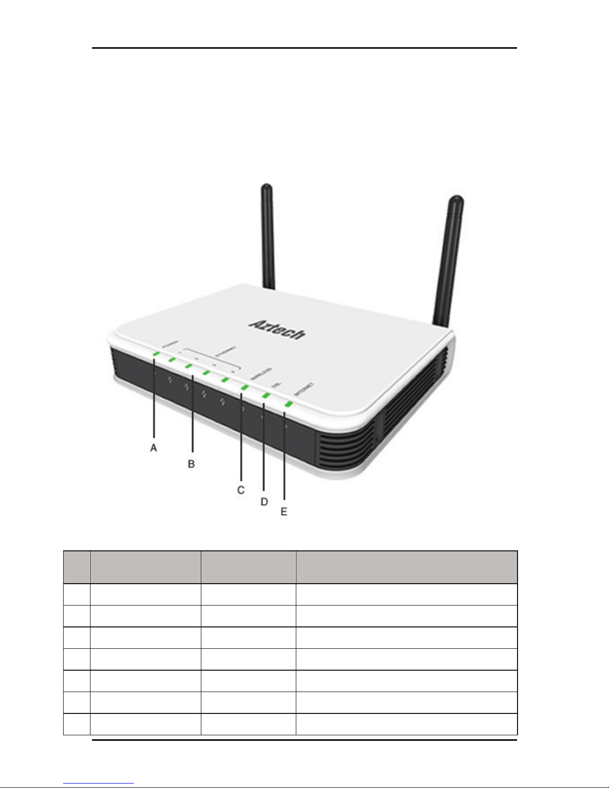
Front Panel
The LEDs on the front panel gives you an idea about the power and connection status.
Label Action Description
A POWER Off No power is supplied to the device
Steady light Connected to an AC power supply
B ETHERNET Off No Ethernet connection
Steady light Connected to an Ethernet port
Blinking light Transmitting/Receiving data
C WIRELESS Off Access point is disabled
Steady light Access point is enabled
Page 9 of 129
Page 10
User Manual
Blinking light Transmitting/Receiving data
D DSL Off No DSL signal
Blinking light Establishing DSL signal
Steady light DSL signal is established
E INTERNET Off No Internet connection
Steady green light Connected to the Internet
Blinking green light Transmitting/Receiving data
Red Connection attempt failed
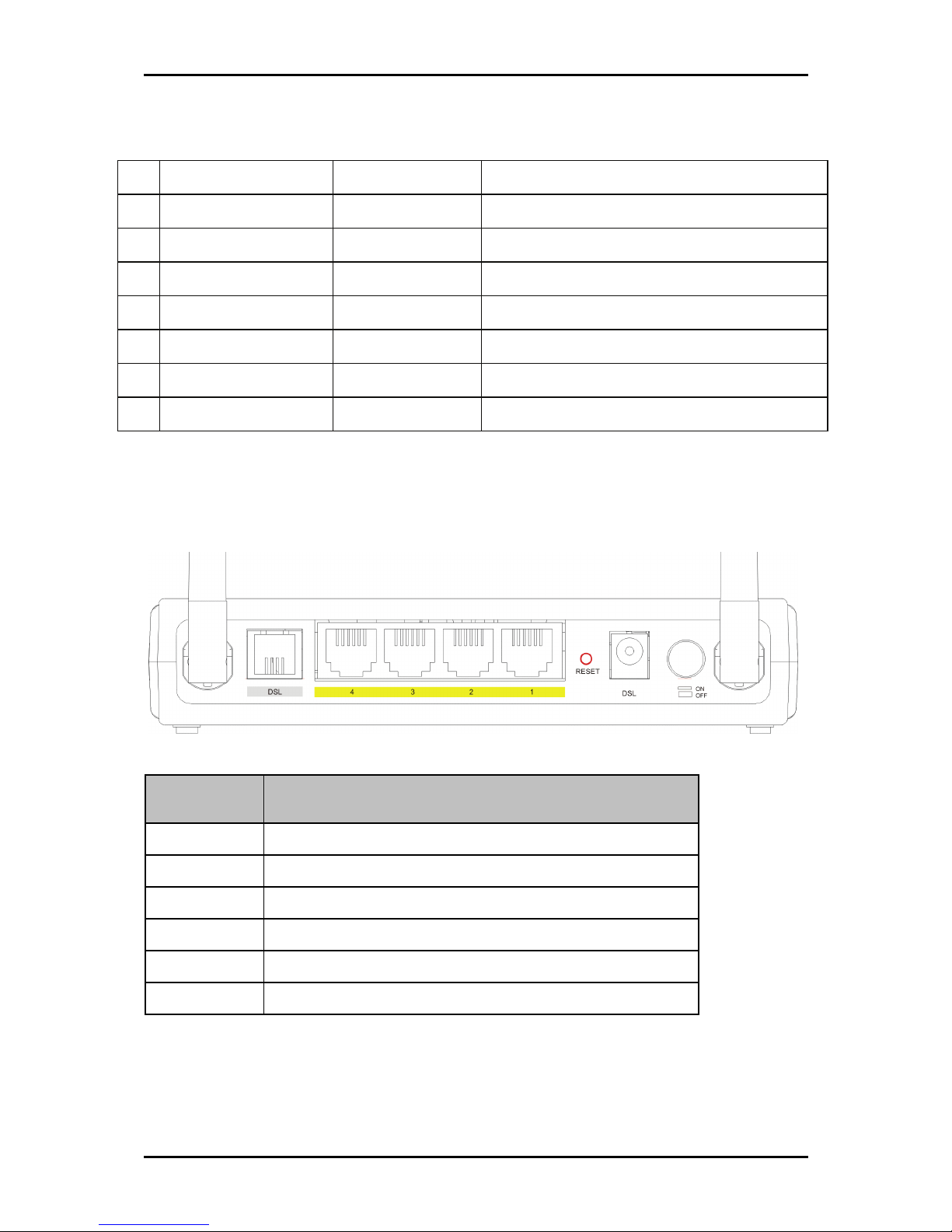
Back Panel
The back panel provides ports to power up and connect the router into the network.
ck Panel
Back Panel
Ba
Back PanelBack Panel
Label
Label Used for…
LabelLabel
DSL
DSL Connecting the telephone cable
DSLDSL
ETHERNET 1
ETHERNET 1----4444 Connecting with computers/devices through Ethernet cable
ETHERNET 1ETHERNET 1
RESET
RESET Resetting the device. Press for 10 seconds to reset.
RESETRESET
9V DC
9V DC Connecting with the 9V power adapter
9V DC9V DC
ON/OFF
ON/OFF Switching the device on/off
ON/OFFON/OFF
Used for…
Used for…Used for…
Antenna
Antenna Sending/receiving wireless signals
AntennaAntenna
Page 10 of 129
Page 11
User Manual
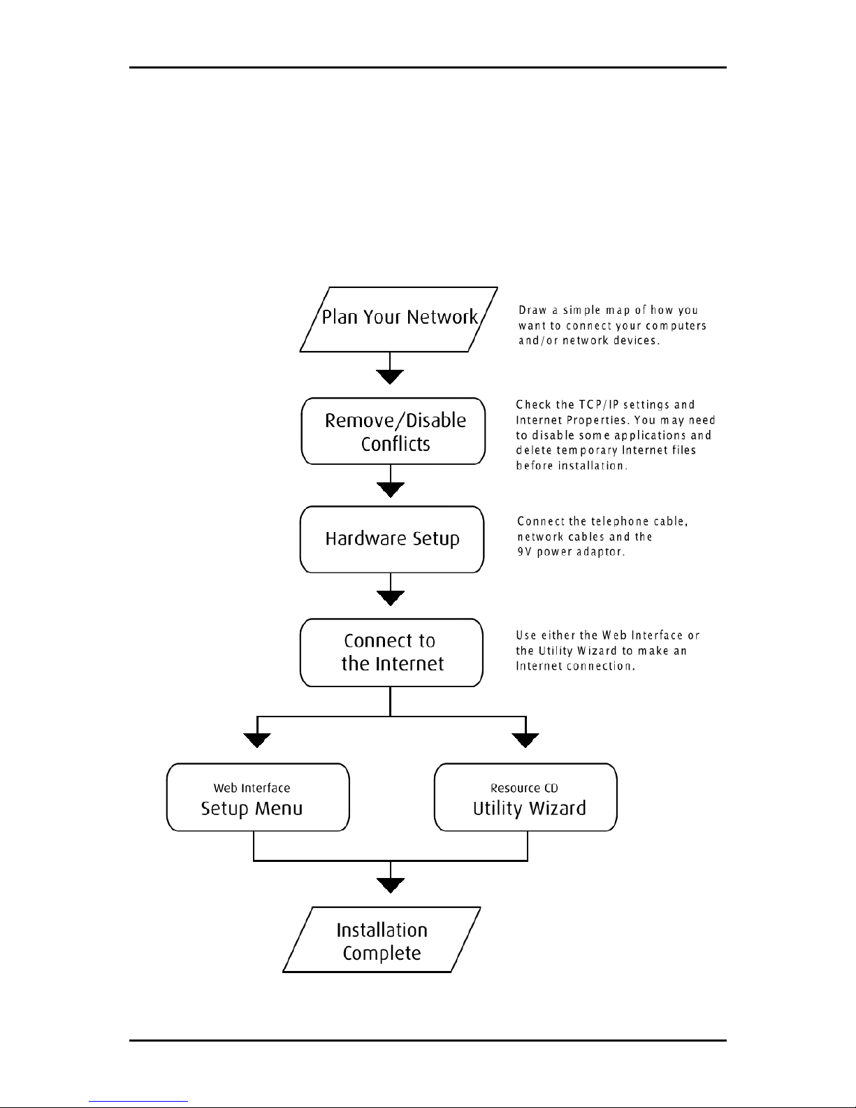
Getting Started
Setting up the device is easy. The flowchart below provides an outline of the steps you
need to complete the installation. There are brief descriptions beside each step to help
you along. Detailed instructions are provided in the subsequent pages.
Page 11 of 129
Page 12
User Manual
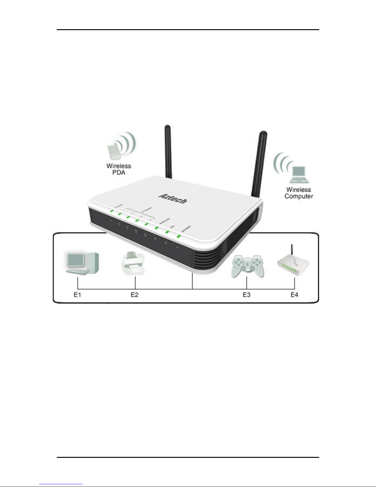
Planning Your Network
Before moving ahead to setup your network, it is a good idea to draw out a network
diagram to help identify the devices and plan out how to connect these devices. The
illustration below is an example of a network diagram.
Sample network diagram
Sample network diagram
Sample network diagramSample network diagram
To create a network diagram:
For wireless devices, identify the wireless devices you want to include in the
network
For wired devices, identify which router port you want to use for each device.
Page 12 of 129
Page 13

User Manual
Remove or Disable Conflicts
To make sure the router installation moves on smoothly, you need to remove or disable
conflicts that may interfere the installation. Probable conflicts may include:
Internet sharing applications
Proxy software
Security software
TCP/IP settings
Internet properties
Temporary Internet files
Internet Sharing, Proxy, and Security Applications
Internet sharing, proxy software, and firewall applications may interfere with the router
installation. These should be removed or disabled before you install and configure the
router.
If you have any of the following or similar applications installed on your computer,
remove or disable them according to the manufacturer’s instructions.
Internet S
Internet Sharing Applications
Internet SInternet S
Microsoft Internet Sharing WinGate Symantec
WinProxy Zone Alarm
haring Applications Proxy Software
haring Applicationsharing Applications
Proxy Software Security Software
Proxy SoftwareProxy Software
Security Software
Security SoftwareSecurity Software
Page 13 of 129
Page 14

User Manual
Configuring TCP/IP Settings
Use the default TCP/IP settings to allow the router to provide a network address to the
computer,
To set the TCP/IP properties:
1. Select Start
2. Enter control
your computer.
3. Right-click LAN
Pro
Properties
ProPro
4. Select Internet Protocol (TCP/IP)
Protocol (TCP/IP)
Protocol (TCP/IP) dialog box.
Protocol (TCP/IP)Protocol (TCP/IP)
5. Select Obtain an IP address automatically
6. Click OK
7. Click OK
Start > Run
Start Start
control ncpa.cpl
control control
perties dialog box.
perties perties
Internet Protocol (TCP/IP) and then click Properties
Internet Protocol (TCP/IP)Internet Protocol (TCP/IP)
Obtain an IP address automatically.
Obtain an IP address automaticallyObtain an IP address automatically
OK to close the Internet Protocol (TCP/IP)
OKOK
OK to close the Local Area Connection Properties
OK OK
Run. This opens the Run
RunRun
ncpa.cpl and then click OK
ncpa.cpl ncpa.cpl
LAN and then select Properties
LAN LAN
Internet Protocol (TCP/IP) dialog box.
Internet Protocol (TCP/IP) Internet Protocol (TCP/IP)
Local Area Connection Properties dialog box.
Local Area Connection Properties Local Area Connection Properties
Run dialog box.
Run Run
OK. This opens the Network Connections
OKOK
Properties. This opens the Local Area Connection
PropertiesProperties
Configuring Internet Properties
Network Connections in
Network Connections Network Connections
Local Area Connection
Local Area Connection Local Area Connection
Properties. This opens the Internet
PropertiesProperties
Internet
Internet Internet
To set the Internet Properties:
1. Select Start
2. Enter control
dialog box.
3. Click Connections
4. In the Dial
connection
connection.
connectionconnection
5. Click OK
Page 14 of 129
Start > Run
Start Start
control inetcpl.cpl
control control
Connections tab.
Connections Connections
OK to close the Internet Properties
OKOK
Run. This opens the Run
RunRun
inetcpl.cpl and then click OK
inetcpl.cpl inetcpl.cpl
Dial----up and Virtual Private Network settings
up and Virtual Private Network settings pane, select Never dial a
DialDial
up and Virtual Private Network settingsup and Virtual Private Network settings
Run dialog box.
Run Run
OK. This opens the Internet Properties
OKOK
Internet Properties dialog box.
Internet PropertiesInternet Properties
Internet Properties
Internet Properties Internet Properties
Never dial a
Never dial a Never dial a
Page 15

User Manual
Removing Temporary Internet Files
Temporary Internet files are files from Web sites that are stored in your computer. Delete
these filed to purge the Internet cache and remove footprints left by the Web pages you
visited.
To remove temporary Internet files:
1. Select Start
2. Enter control
3. Double-click Internet Options
4. In the Temporary Internet Files
5. Click Delete Files
6. Click OK
Start > Run
Start Start
control and then click OK
controlcontrol
Temporary Internet Files pane, click Delete Cookies
Temporary Internet Files Temporary Internet Files
Delete Files.
Delete FilesDelete Files
OK to close the Internet Properties
OKOK
Run. This opens the Run
RunRun
Internet Options. This opens the Internet Options dialog box.
Internet OptionsInternet Options
Internet Properties dialog box.
Internet PropertiesInternet Properties
Run dialog box.
Run Run
OK. This opens the Control Panel
OKOK
Control Panel.
Control PanelControl Panel
Delete Cookies.
Delete CookiesDelete Cookies
Page 15 of 129
Page 16
User Manual
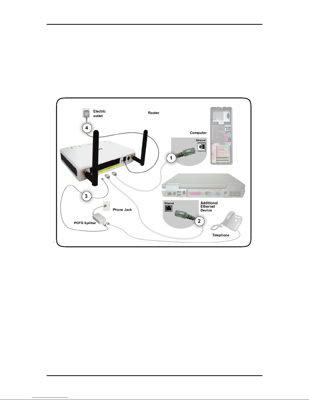
Hardware Setup
When installing the router, the common practice is to have the router, the main
computer, and phone jack in the same room. The room should also have enough
electrical outlets to match your needs.
To setup the hardware:
1. Plug one end of the Ethernet cable from the router’s ETHERNET
ETHERNET port and then plug
ETHERNET ETHERNET
the other end into the Ethernet port in your computer.
2. If you have another device you need to connect through wire into the router, use
another piece of Ethernet cable. Plug one end of the Ethernet cable from the
computer’s Ethernet port and then plug the other end into an available Ethernet
port.
3. Plug one end of the telephone cable from the POTS Splitter’s ADSL
plug the other end into the router’s DSL
Page 16 of 129
DSL port
DSL DSL
ADSL port and then
ADSL ADSL
Page 17

POTS Splitter
POTS Splitter
POTS SplitterPOTS Splitter
A phone line can carry phone call and Internet signals. When you enable the phone
line for high speed Internet, the connection produces high-pitched tones when using
the phone. Installing a Plain Old Telephone Service (POTS) splitter separates the two
signals and eliminates the noise.
To setup the telephone POTS Splitter:
To setup the telephone POTS Splitter:
To setup the telephone POTS Splitter:To setup the telephone POTS Splitter:
a. Locate the phone jack in your house.
b. Insert the POTS Splitter into the phone jack.
c. Plug one end of the telephone cable from the POTS Splitter’s TEL
the other end into the telephone.
4. Connect the power adapter from the router’s 9V DC
User Manual
TEL port and then plug
TELTEL
9V DC port into the electrical outlet.
9V DC 9V DC
Page 17 of 129
Page 18

User Manual
Connecting to the Internet
There are two ways to connect to the Internet. You can either use the Web Interface or
the Utility Wizard.
Connecting Via the Web Interface
To connect to the Inter via the Web Interface:
1. Open your browser.
2. Enter 10.100.1.1
10.100.1.1 in the address field and then press Enter
10.100.1.1 10.100.1.1
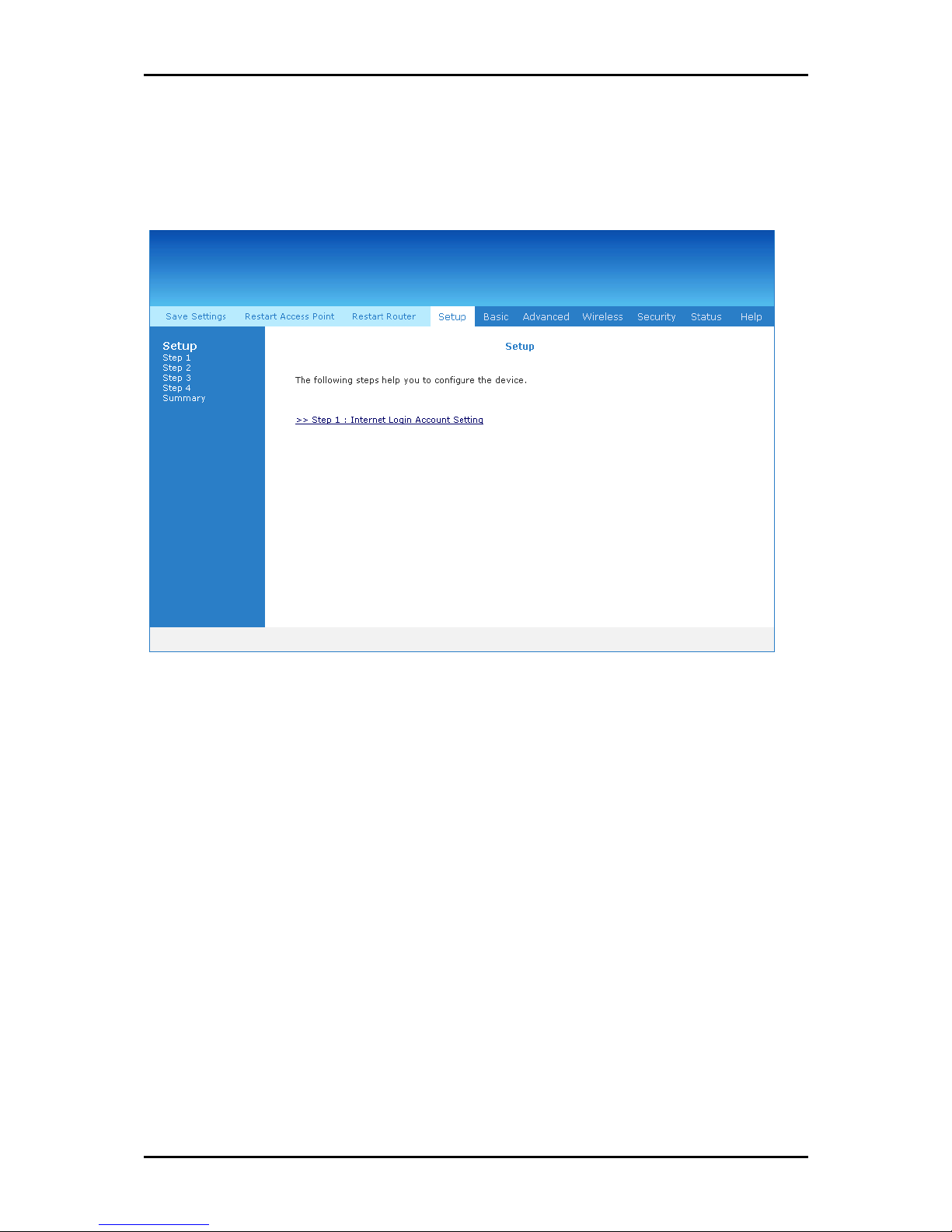
page of the web interface.
Setup Page
Setup Page
Setup PageSetup Page
Enter. This opens the Setup
EnterEnter
Setup
Setup Setup
Page 18 of 129
Page 19

User Manual
3. Click Step 1: Internet Login Account Setting
4. Enter the User ID
Step 1: Internet Login Account Setting. This opens the Internet Logi
Step 1: Internet Login Account SettingStep 1: Internet Login Account Setting
Setting
Setting page.
Setting Setting
Internet Login Account Setting page
Internet Login Account Setting page
Internet Login Account Setting pageInternet Login Account Setting page
User ID, Password
User IDUser ID
Password, Protocol
PasswordPassword
Protocol, VP1
ProtocolProtocol
VP1, and VCI
VP1VP1
Internet Login Account
Internet LogiInternet Logi
VCI for your account. These are the
VCIVCI
n Account
n Account n Account
account information from your service provider.
5. Click Next
Next. This opens the Wireless LAN Configuration
NextNext
Wireless LAN Configuration page.
Wireless LAN Configuration Wireless LAN Configuration
Wireless LAN Configuration page
Wireless LAN Configuration page
Wireless LAN Configuration pageWireless LAN Configuration page
Page 19 of 129
Page 20
User Manual
6. Enter an SSID, Country Standard,
7. Select Yes
8. Click Next
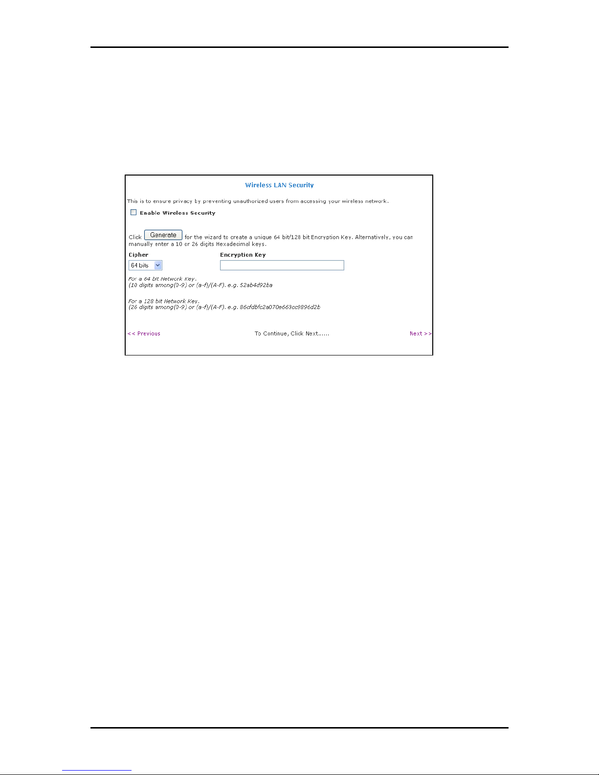
Wireless LAN Security
Wireless LAN Security
Wireless LAN SecurityWireless LAN Security
SSID, Country Standard, and Wireless Channel
SSID, Country Standard, SSID, Country Standard,
Yes or No
Yes Yes
Next. This opens the Wireless LAN Security
NextNext
No to specify if you want to hide your wireless network name or not.
No No
Wireless LAN Security page.
Wireless LAN Security Wireless LAN Security
Wireless Channel.
Wireless ChannelWireless Channel
9. Select Enable Wireless Security
10. Enter an Encryption Key
Enable Wireless Security.
Enable Wireless SecurityEnable Wireless Security
Encryption Key or click Generate
Encryption Key Encryption Key
Generate to allow the router to create an
Generate Generate
alphanumeric encryption key for you. The Encryption key will be used to establish
the wireless network connection of wireless devices.
Page 20 of 129
Page 21
User Manual
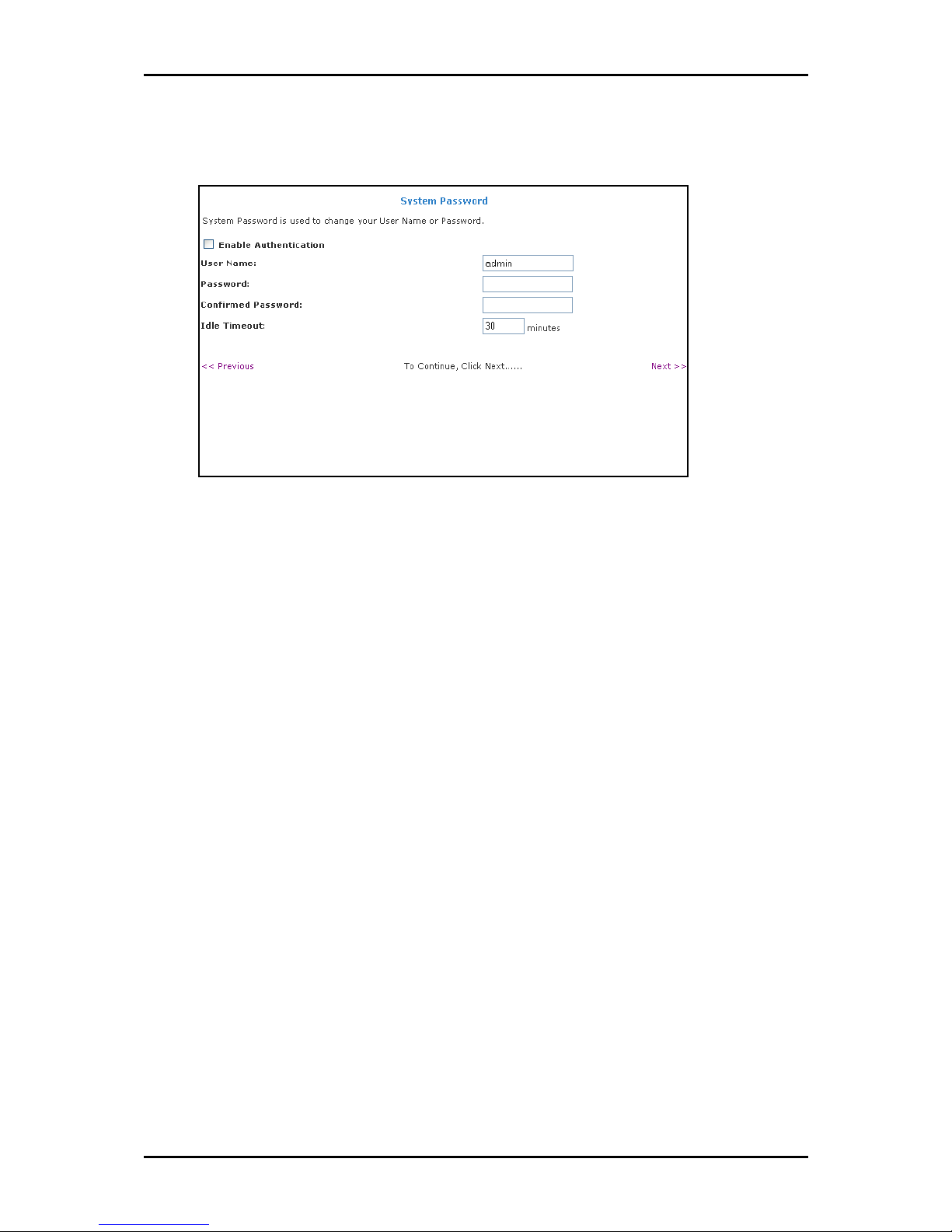
11. Click Next
12. Select Enable Authentication
13. Enter User Name, Password,
Next. This opens the System Password
NextNext
System Password page
System Password page
System Password pageSystem Password page
Enable Authentication.
Enable AuthenticationEnable Authentication
User Name, Password, and Confirm Password
User Name, Password, User Name, Password,
System Password page.
System Password System Password
Confirm Password.
Confirm PasswordConfirm Password
14. Enter the number of minutes for Idle Timeout
15. Click Next
16. Click Finish
Next. This opens the Summary
NextNext
Finish.
FinishFinish
Summary page.
Summary Summary
Idle Timeout.
Idle TimeoutIdle Timeout
Page 21 of 129
Page 22
User Manual
17. This opens a dialog box asking if you want to save and restart the router. Click OK
OK.
OKOK
The router will take about two minutes to save the settings and establish a
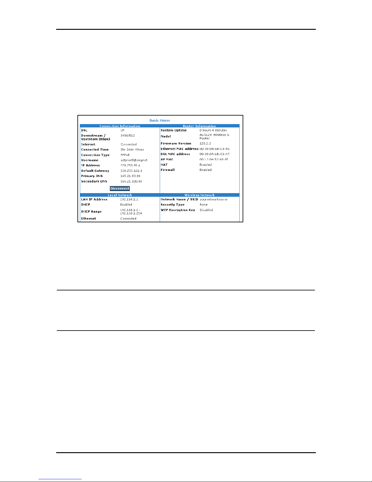
connection with your Internet service provider. Afterwards, the Basic Home page
opens to give you a summary of the account settings.
Basic Home page
Basic Home page
Basic Home pageBasic Home page
Connecting Via the Utility Wizard
The Setup Wizard can also be used to configure your router. However, this only runs on
Windows operating systems.
Notes:
Notes: Microsoft Windows 2000 users may be asked to confirm the installation. To confirm,
Notes:Notes:
click Yes
Yes.
YesYes
Microsoft Windows XP users may be asked to confirm the installation. To confirm, click
Continue Anyway
Continue Anyway.
Continue AnywayContinue Anyway
To use the Setup Wizard:
1. Insert the Resource CD
2. If the utility does not launch automatically, select Sta
(where D:
3. Select your router model and then follow the installation procedure.
4. After a successful connection, on the router’s front panel, INTERNET
Resource CD into your CD-ROM.
Resource CDResource CD
D: is your CD-ROM drive), and then click OK
D:D:
OK. This opens the Setup Utility
OKOK
Start
rt > Run
StaSta
rtrt
Run, enter D:
RunRun
INTERNET lights up.
INTERNET INTERNET
D:\\\\Setup.exe
Setup.exe
D:D:
Setup.exe Setup.exe
Setup Utility.
Setup UtilitySetup Utility
Page 22 of 129
Page 23

User Manual
Connecting Wireless Devices
After you setup the device settings through the main computer, you can connect other
devices with wireless capabilities. Wireless devices relieve you from the task of laying
out cables and allow you to use the Internet connection from your router.
Your router allows you to connect with several wireless devices
Your router allows you to connect with several wireless devices
Your router allows you to connect with several wireless devicesYour router allows you to connect with several wireless devices
To the connect with wireless devices:
1. Turn on your wireless device.
2. Open the software you use to detect a wireless connection. This opens a window
to ask for the connection settings.
3. Enter the connection settings. These settings are defined in your router during
setup. For more details about wireless connections, please refer to Wireless Menu.
Page 23 of 129
Page 24

User Manual
About the Web Interface
The Web Interface is used to configure the router settings.
Accessing the Web Manager
To access the Web Manager:
1. Open a browser.
2. Enter the router’s IP Address. The default IP Address is 10.100.1.1
3. When authentication is enabled, the log in page will appear. In the login page,
enter the User Name
default password is also admin.
User Name and Passwo
User Name User Name
Password
PasswoPasswo
rd. The default user name is admin and the
rdrd
10.100.1.1.
10.100.1.110.100.1.1
Components
Buttons, commands, and menus make up the browser-based user interface.
Buttons
Apply
Click to implement the configuration changes. Clicking Apply will not implement
the changes when the router is restarted.
Cancel
Click to revert to the last saved configuration.
Page 24 of 129
Page 25

Commands
Save Setting
Click to permanently apply configuration changes.
Restart Router
Restarts the router
Restart Access Point
Restarts the wireless connection
Menus
User Manual
The web interface includes the following menus:
Setup Menu
Basic Menu
Advanced Menu
Wireless Menu
Security Menu
Status Menu
Help Menu
Page 25 of 129
Page 26
User Manual
Setup Menu
The Setup menu is used to complete the initial device configuration.
Setup Menu
Setup Menu
Setup MenuSetup Menu
Page 26 of 129
Page 27
User Manual
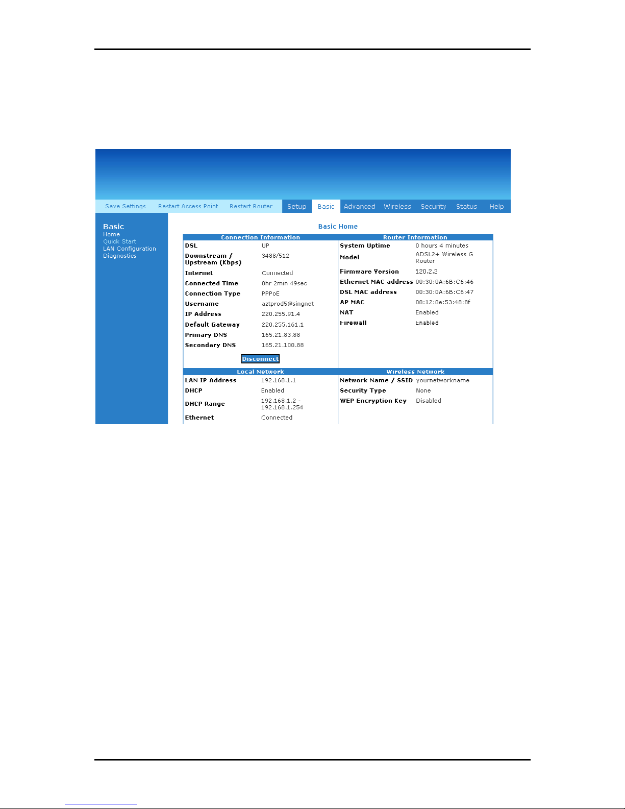
Basic Menu
The Basic Menu provides the Home, Quick Start, LAN Configuration, and Diagnostics links.
Basic Menu
Basic Menu
Basic MenuBasic Menu
Page 27 of 129
Page 28
User Manual
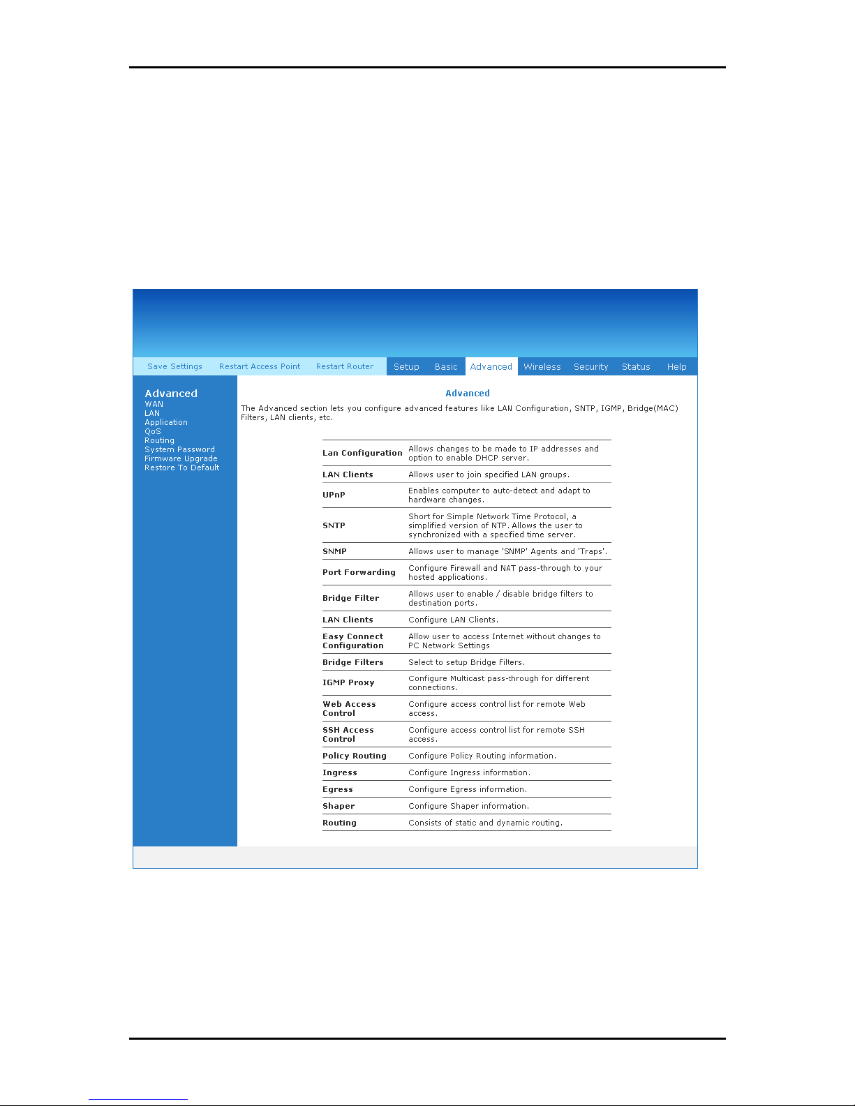
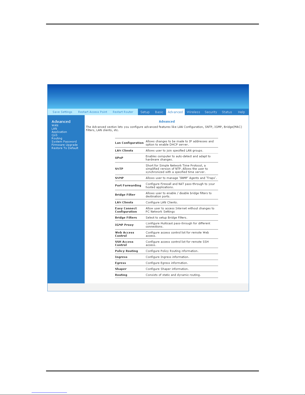
Advanced Menu
The Advanced mode provides advanced configuration settings for existing connections. At
least one WAN connection must be configured before implementing advanced WAN
configuration features. At least one LAN group must be defined before implementing
advanced LAN configuration features.
Advanced Menu
Advanced Menu
Advanced MenuAdvanced Menu
Page 28 of 129
Page 29
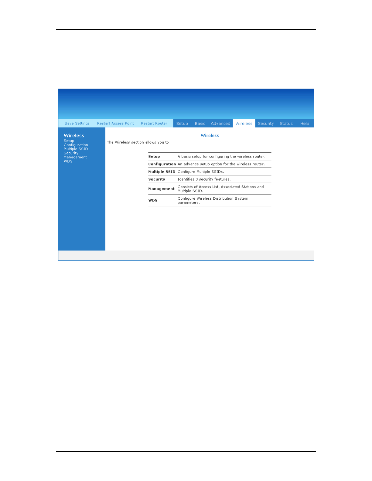
Wireless Menu
Wireless Menu allows you to configure the wireless settings.
User Manual
Wireless Menu
Wireless Menu
Wireless MenuWireless Menu
Page 29 of 129
Page 30
User Manual
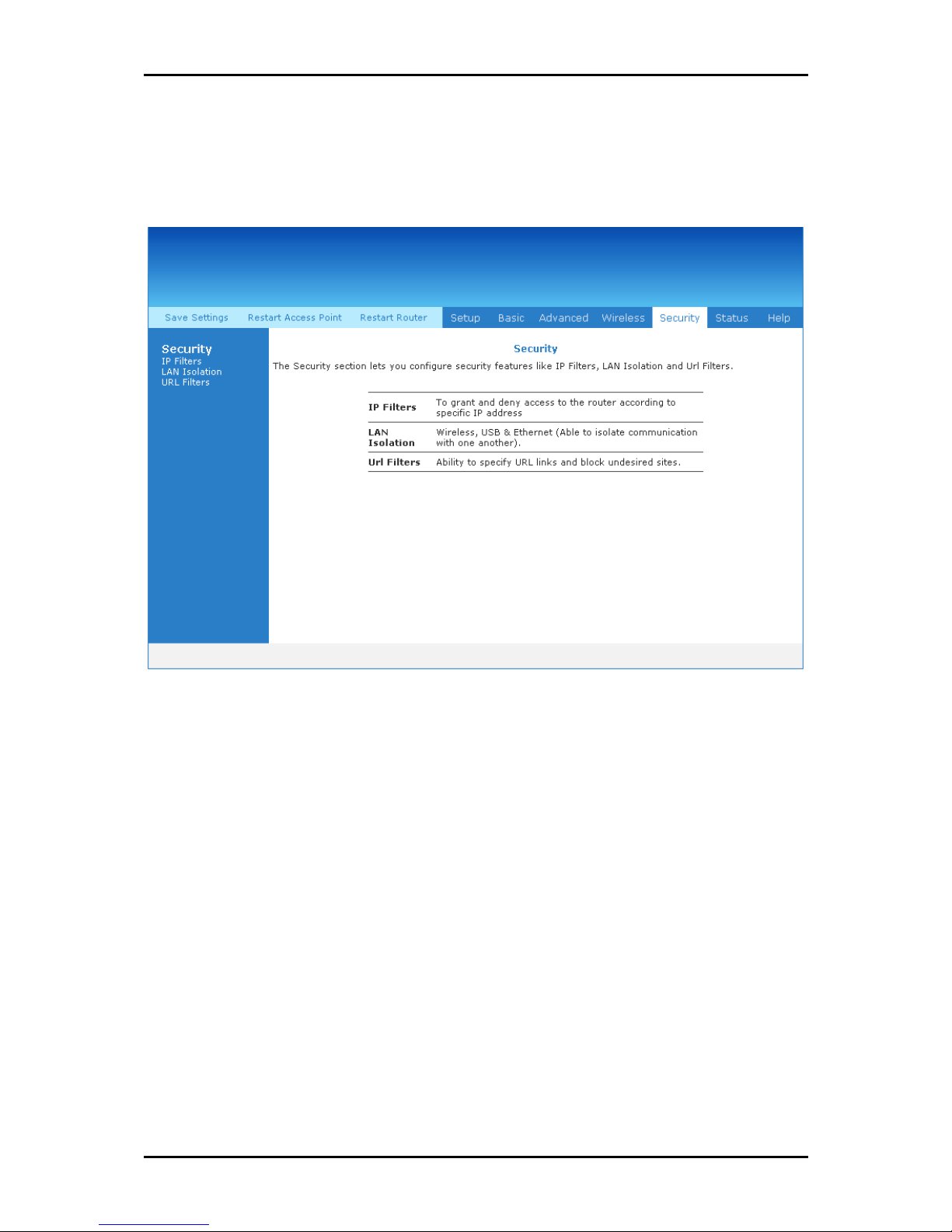
Security Menu
Security Menu allows you to configure security tools like IP Filters and LAN Isolation.
Security Menu
Security Menu
Security MenuSecurity Menu
Page 30 of 129
Page 31

Status Menu
The Status Menu provides the status for different connections or interfaces.
User Manual
Status Menu
Status Menu
Status MenuStatus Menu
Page 31 of 129
Page 32
User Manual
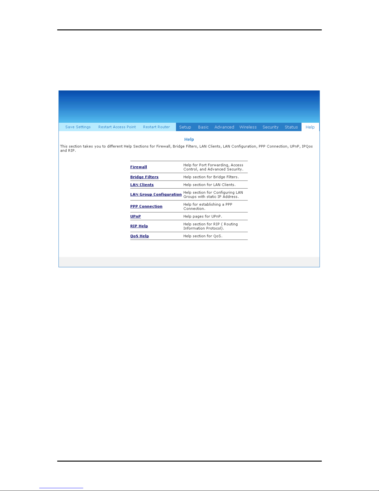
Help Menu
The Help Menu provides documentation about various router features.
Help Menu
Help Menu
Help MenuHelp Menu
Page 32 of 129
Page 33
User Manual
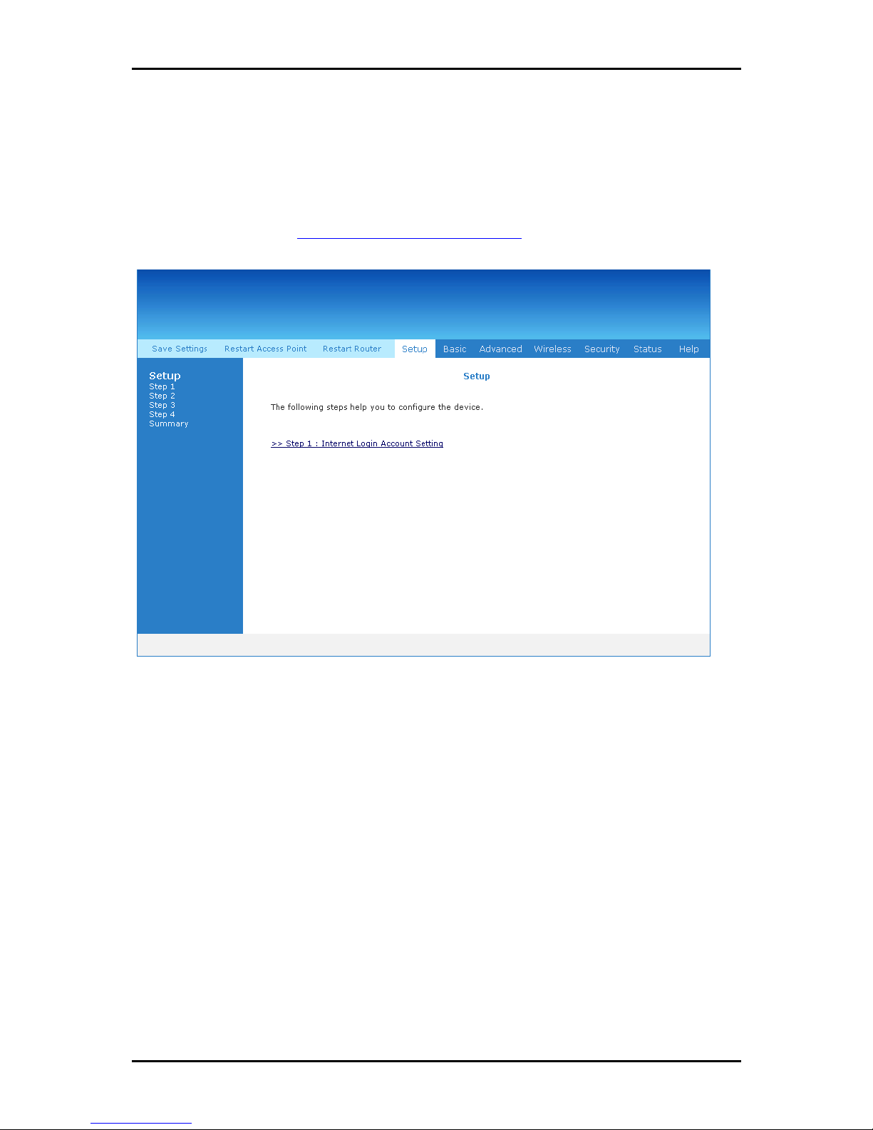
Setup Menu
The Setup Menu provides step by step instructions on how to configure the router
settings. Please refer to Connecting Via the Web Interface.
Setup Menu
Setup Menu
Setup MenuSetup Menu
Page 33 of 129
Page 34
User Manual
Basic Menu
The options for the Basic Menu include:
Home
Quick Start
LAN Configuration
Diagnostics
Basic Menu
Basic Menu
Basic MenuBasic Menu
Page 34 of 129
Page 35

User Manual
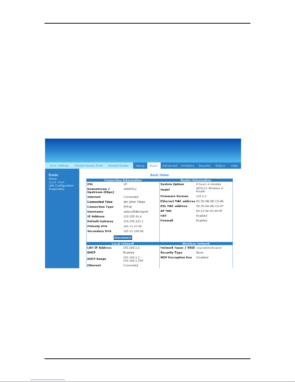
Home
The Home page provides a one-page summary about the Connection Information, Router
Information, Local Network, and Wireless Network settings.
Connection Information
The Connection Information pane gives you an idea about the status of your Internet
connection. This pane includes a Connect/Disconnect button. When clicked, the router
makes an attempt to connect to the Internet using the parameters saved in the router.
Router Information
This pane provides all the necessary information to determine the model, firmware
version, build, Ethernet MAC Address, Wireless MAC Address, NAT status, and Firewall
status.
Local Network Information
The Local Network pane displays the current IP address of the router. It also provides the
DHCP status, DHCP Range, and Ethernet status.
Wireless Network Information
This pane displays the current configuration settings for the router’s access point.
Quick Start
Quick Start gives you the ability to instantly connect to the Internet.
Page 35 of 129
Page 36

User Manual
LAN Configuration
LAN Group Configuration allows you to configure settings for each LAN group. Notice that
you can also view the status of advanced services that can be applied to a LAN group.
Green indicates that the service is enabled, while red indicates that the service is
disabled.
LAN Group Configuration
LAN Group Configuration
LAN Group ConfigurationLAN Group Configuration
Page 36 of 129
Page 37

User Manual
Diagnostics
Diagnostic Test is used for investigating whether the router is properly connected to the
WAN Network. This test may take a few seconds to complete. To perform the test, select
your connection from the list and press the Test button. Before running this test, make
sure you have a valid DSL link.
To run diagnostic test:
1. Select the Basic Menu
2. Click Test
failed, click Help
Basic Menu and then click Diagnostics
Basic Menu Basic Menu
Test. The test status will appear after running the diagnostic test. If a test
TestTest
Help to get the solution.
Help Help
Diagnostics. This opens the Diagnostics
DiagnosticsDiagnostics
Diagnostics page.
DiagnosticsDiagnostics
Ping Test
Once you have your router configured, it is a good idea to make sure you can ping the
network. If you can ping an IP on the WAN side successfully, you should be able to surf
the Internet.
To perform a ping test:
1. Select the Basic
2. Click Ping Test
Basic Menu
Menu and then click Diagnostics
BasicBasic
Menu Menu
Ping Test. This opens the Ping Test
Ping TestPing Test
Ping Test page.
Ping Test Ping Test
Diagnostics.
DiagnosticsDiagnostics
Page 37 of 129
Page 38

User Manual
3. Change or leave the default settings of the following fields:
Enter the IP address to ping
Packet size
Number of echo request
4. Click Test
Test.
TestTest
The ping results are displayed in the page. If the ping test was successful, it
means that the TCP/IP protocol is up and running. If the Ping test failed, you
should restart the router.
Full Modem Test
This test is used to check if your modem is properly connected to the network.
To perform a Full Modem test:
1. Select the Basic
2. Click Full Modem Test
Select your connection and then click Test
Basic Menu
Menu and then click Diagnostics
BasicBasic
Menu Menu
Full Modem Test. This opens the Modem Test
Full Modem TestFull Modem Test
Test.
TestTest
Diagnostics.
DiagnosticsDiagnostics
Modem Test page.
Modem Test Modem Test
Page 38 of 129
Page 39
Advanced Menu
This chapter provides advanced configuration options for your router.
User Manual
Advanced Menu
Advanced Menu
Advanced MenuAdvanced Menu
Page 39 of 129
Page 40

User Manual
WAN
Wide Area Network refers to the configurations you perform to establish an Internet
connection. There are several types of WAN connections that require different settings.
New Connection
Your router supports the creation of new connections. If you have multiple virtual
connections, you may need to utilize the static routing capabilities of the modem to pass
data correctly.
WAN connections types include:
PPPoE Connection
PPPoA Connection
Static Connection
DHCP Connection
Bridge Connection
CLIP Connection
Page 40 of 129
Page 41
User Manual
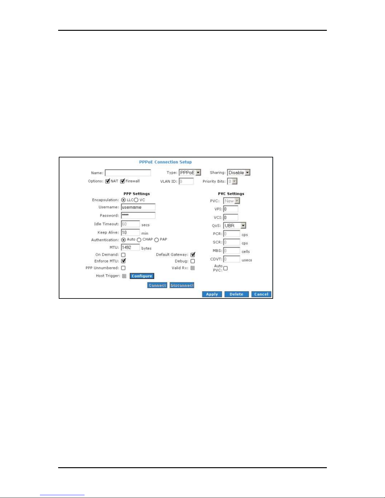
PPPoE Connection
PPP, or point-to-point protocol, is a method of establishing a network connection/session
between network hosts. PPPoE is a protocol for encapsulating PPP frames in Ethernet
frames and is described in RFC 2516. PPPoE provides the ability to connect to a network
of hosts over a simple bridging access device to a remote access concentrator. With this
model, each router uses its own PPP stack. Access control, billing, and type of service
control can all be done on a per-user rather than per-site basis.
New PPPoE Connection Setup
New PPPoE Connection Setup
New PPPoE Connection SetupNew PPPoE Connection Setup
Page 41 of 129
Page 42

User Manual
PPPoA Connection
PPPoA is also known as RFC 2364. It is a method of encapsulating PPP packets in ATM
cells that are carried over the DSL line. PPP, or point-to-point protocol, is a method of
establishing a network connection/session between network hosts. It usually provides a
mechanism of authenticating users. Logical link control (LLC) and virtual circuit (VC) are
two different methods of encapsulating the PPP packet. Contact your service provider to
determine which encapsulation is being used on your Internet connection.
New PPPoA Connection Setup
New PPPoA Connection Setup
New PPPoA Connection SetupNew PPPoA Connection Setup
Page 42 of 129
Page 43
User Manual
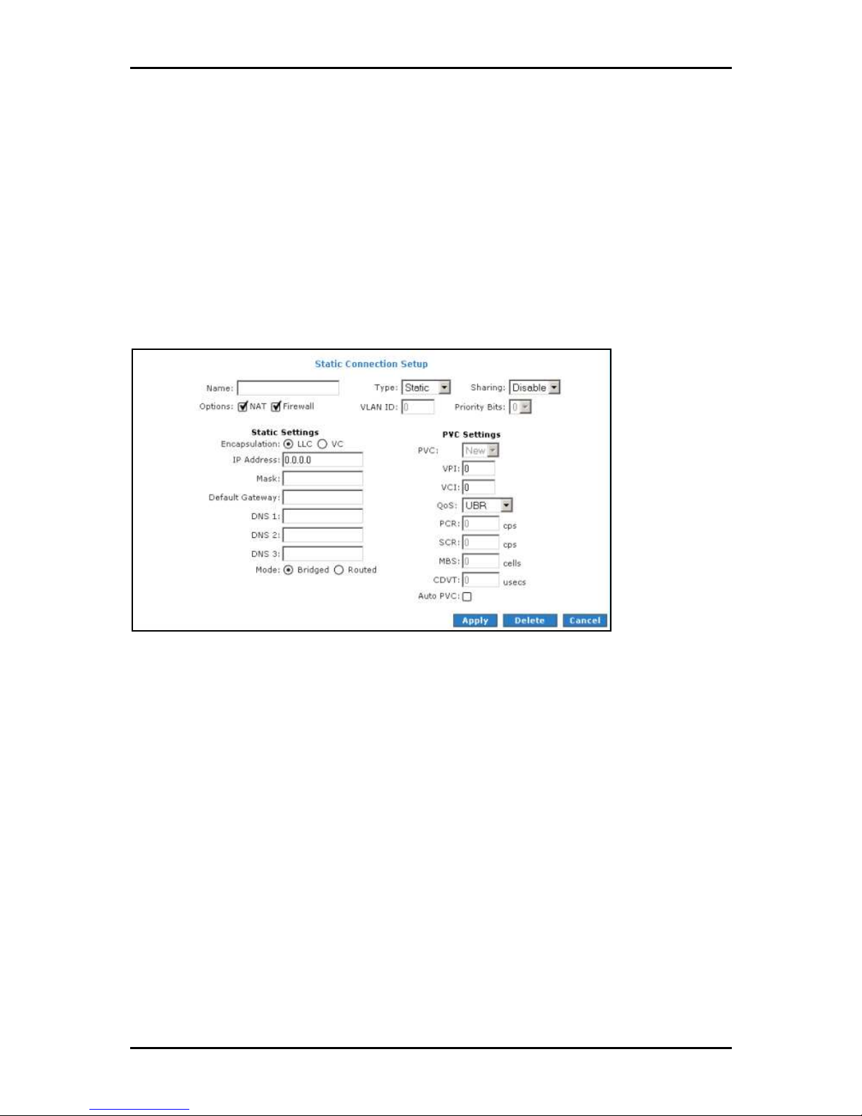
Static Connection
Static connection type is used whenever a known static IP address is assigned to the
router. Additional addressing information such as the subnet mask and the default
gateway must also be specified. Up to three domain name server (DNS) addresses can be
identified. These servers resolve the name of the computer to the IP address mapped to
it and thus enable you to access other web servers by typing the symbolic name (host
name).
New Static Connection Setup
New Static Connection Setup
New Static Connection SetupNew Static Connection Setup
Page 43 of 129
Page 44

User Manual
DHCP Connection
DHCP allows the router to automatically obtain the IP address from the server. This option
is commonly used in when the IP is dynamically assigned and is not known prior to
assignment.
New DHCP Connection Setup
New DHCP Connection Setup
New DHCP Connection SetupNew DHCP Connection Setup
Page 44 of 129
Page 45

User Manual
Bridge Connection
A bridge connection does not assign any IP address to the WAN interface. NAT and
firewall rules are not enabled. This connection method makes the router act as a bridge
for passing packets between the WAN interface and the LAN interface.
New Bridge Connection Setup
New Bridge Connection Setup
New Bridge Connection SetupNew Bridge Connection Setup
Page 45 of 129
Page 46

User Manual
CLIP Connection
Classical IP over ATM (CLIP) Connection Setup page (CLIP) provides the ability to transmit
IP packets over an ATM network. CLIP support encapsulates an IP datagram in an AAL5
PDU frame using RFC 2225 and it uses an ATM-aware version of the address resolution
protocol (ATMARP).
CLIP Connection Setup
CLIP Connection Setup
CLIP Connection SetupCLIP Connection Setup
Page 46 of 129
Page 47

User Manual
ADSL Modulation
ADSL Modulation allows you to select any combination of DSL training modes. Leave the
default value if you are unsure or the service provider did not provide this information. In
most cases, this screen should not be modified.
ADSL Modulation
ADSL Modulation
ADSL ModulationADSL Modulation
Page 47 of 129
Page 48
User Manual
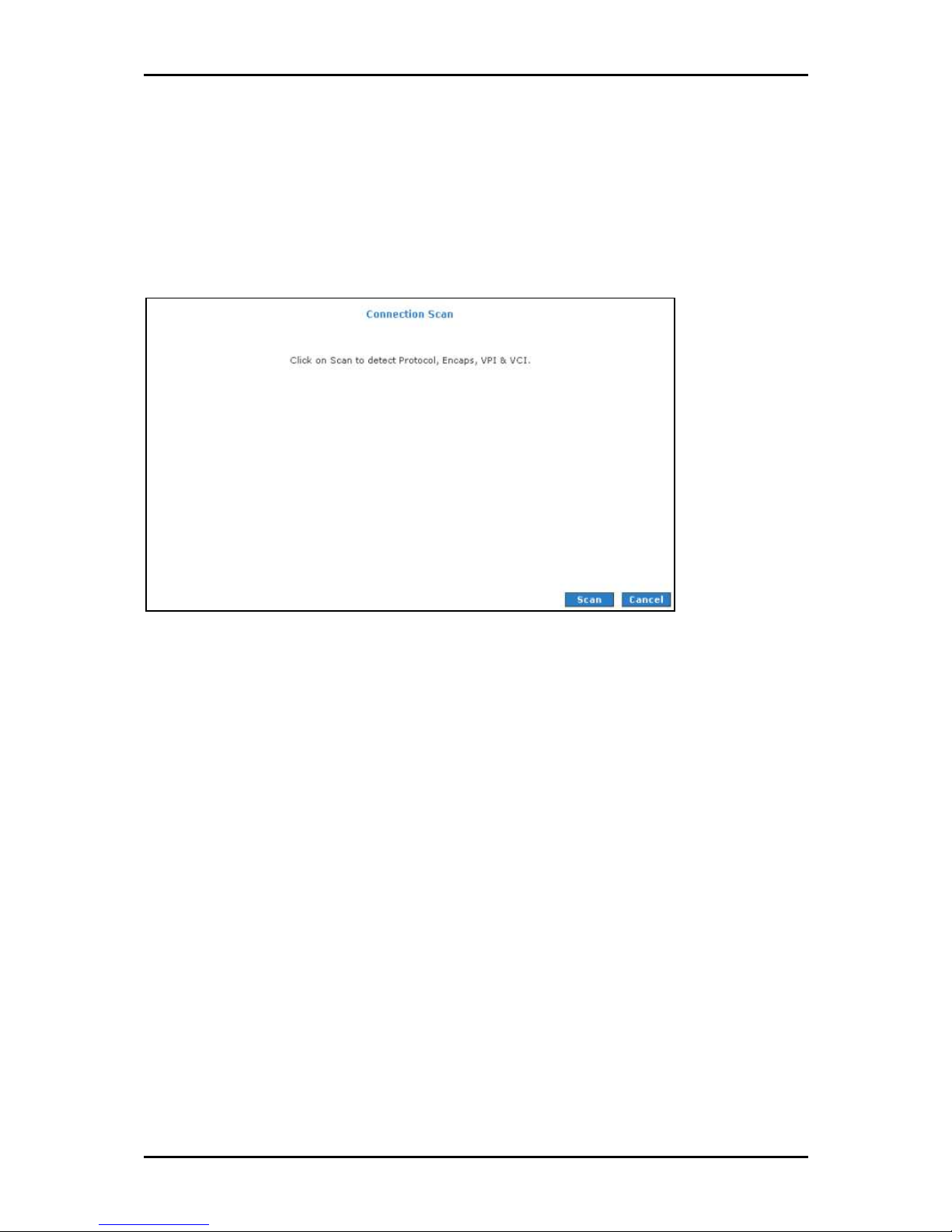
Connection Scan
This feature helps users to detect the PVC settings provided by the service provider.
Before the router can begin scanning the connection, the telephone line has to be
plugged into the router.
Connection Scan
Connection Scan
Connection ScanConnection Scan
To perform connections scan:
1. Select the Advanced Me
2. Select WAN > Connection Scan
3. Click Scan
Advanced Menu
Advanced MeAdvanced Me
WAN > Connection Scan.
WAN > Connection ScanWAN > Connection Scan
Scan.
ScanScan
nu.
nunu
Page 48 of 129
Page 49

User Manual
LAN
The router is preconfigured to automatically provide IP addresses to all the computers in
the Local Area Network (LAN). Your router allows you to create and configure LAN
groups.
LAN Configuration
Your router’s default IP address and subnet mask are 10.100.1.1 and 255.255.255.0,
respectively. This subnet mask allows the router to support 254 users. If you want to
support more users, you need to edit the subnet mask but remember that the DHCP
server is defaulted to only give out 255 IP addresses. If you change your gateways’ IP
address and you have DHCP enabled, the DHCP configuration must reside within the
same subnet. The default gateway is the routing device used to forward all traffic that is
not addressed to a station within the local subnet. Your ISP will provide you with the
default gateway Address.
LAN Configuration
LAN Configuration
LAN ConfigurationLAN Configuration
Page 49 of 129
Page 50

User Manual
To configure the LAN groupings:
1. Select the Advanced Menu
2. Select LAN > LAN Configuration
3. Select ETHERNET
Advanced Menu.
Advanced MenuAdvanced Menu
LAN > LAN Configuration.
LAN > LAN ConfigurationLAN > LAN Configuration
ETHERNET in LAN group 1
ETHERNETETHERNET
LAN group 1 and then click < Remove
LAN group 1 LAN group 1
to the ETHERNET interface because it does not belong to any LAN group.
4. Select ETHERNET
in LAN group 1, Configure
ETHERNET from Interfaces
ETHERNET ETHERNET
Interfaces and then click Add >
Interfaces Interfaces
Configure will appear in LAN group 2
Configure Configure
additional configurations.
5. To temporarily activate the settings, click Apply
6. To make changes permanent, click Save Settings
Save Settings.
Save SettingsSave Settings
< Remove. No packets will be sent
< Remove< Remove
Add > under LAN group 2
Add > Add >
LAN group 2 to allow the definition of
LAN group 2 LAN group 2
Apply.
ApplyApply
LAN group 2. Just like
LAN group 2LAN group 2
Page 50 of 129
Page 51

User Manual
LAN Group Configuration
LAN Group Configuration allows you to configure settings for each LAN group. Notice that
you can also view the status of advanced services that can be applied to a LAN group.
Green indicates that the service is enabled, while red indicates that the service is
disabled.
LAN Group Configuration
LAN Group Configuration
LAN Group ConfigurationLAN Group Configuration
Category
Category Field
CategoryCategory
Unmanaged Unmanaged is a state when the LAN group is not
Obtain an IP address
automatically
IP Address You can retrieve/renew an IP address from the DHCP
Netmask The subnet mask of your router.
Field Description
FieldField
When this function is enabled, your router acts like a
Description
DescriptionDescription
configured and no IP address has been assigned to the
bridge.
client and requests an IP address from the DHCP server
on the LAN side.
server using the Release and Renew buttons.
Page 51 of 129
Page 52

User Manual
PPP IP Address Enables/disables PPP unnumbered feature.
IP Address The IP address should be different but within the same
subnet as the WAN-side IP address.
Use the following Static IP
address
This field enables you to change the IP address of the
router.
IP Address The default IP address of the router (as shown) is
10.100.1.1.
Netmask The default subnet mask of your router is 255.255.255.0.
This subnet allows the router to support 254 users. If you
want to support a larger number of users you can
change the subnet mask.
Default Gateway The default gateway is the routing device used to
forward all traffic that is not addressed to a station
within the local subnet. Your ISP provides you with the
IP address of the default gateway.
Host Name The host name is used in conjunction with the domain
name to uniquely identify the router. It can be any
alphanumeric word that does not contain spaces.
Domain The domain name is used in conjunction with the host
name to uniquely identify the router. To access the web
pages of the router you can type 10.100.1.1 (the IP
address) or mygateway1.ar7 (Host Name.Domain).
Enable DHCP Server Enables/disables DHCP. By default, your router has the
DHCP server (LAN side) enabled. If you already have a
DHCP server running on your network, you must disable
one of the two DHCP servers.
Assign ISP DNS,
SNTP
Enable/disables the Assign ISP DNS, SNTP feature when
the DHCP server of your router has been enabled. To
learn more, please refer to Assign ISP DNS, SNTP.
Start IP The Start IP Address is where the DHCP server starts
issuing IP addresses. This value must be greater than the
IP address value of the router. For example, if the IP
address of the router is 10.100.1.1 (default), then the
starting IP address must be 192.168.1.2 (or higher).
End IP The End IP Address is where the DHCP server stops
issuing IP addresses. The ending address cannot exceed
a subnet limit of 254; hence the max value for the
default gateway is 192.168.1.254. If the DHCP server
runs out of DHCP addresses, users do not get access to
Page 52 of 129
Page 53

User Manual
network resources. If this happens, you can increase the
Ending IP address (to the limit of 254) or reduce the
lease time.
Lease Time The Lease Time is the amount of time that a network
user is allowed to maintain a network connection to the
router using the current dynamic IP address. At the end
of the Lease Time, the lease is either renewed or the
DHCP server issues a new IP. The amount of time is in
units of seconds. The default value is 3600 seconds (1
hour). The maximum value is 999999 seconds
(About 278 hours).
Enable DHCP Relay In addition to the DHCP server feature, the router
supports the DHCP relay function. When the router is
configured as DHCP server, it assigns the IP addresses to
the LAN clients. When the gateway is configured as
DHCP relay, it is responsible for forwarding the requests
and responses negotiated between the DHCP clients and
the server.
Relay IP The IP address of the DHCP relay server.
Server and Relay Off When the DHCP server and relay functions are turned
off, the network administrator must carefully configure
the IP address, Subnet Mask, and DNS settings of every
host on your network. Do not assign the same IP address
to more than one host. Also, your router must reside on
the same subnet as all the other hosts.
Assign ISP DNS, SNTP
When you enable the DHCP server, the router dynamically assigns IP addresses to
computers in the local network. The router provides its own LAN IP address (10.100.1.1)
as both the gateway and the DNS server.
The router has a choice of advertising its own IP address (10.100.1.1) as the DNS server
or providing the DNS that was received from the WAN. This can be configured by
enabling/disabling Assign ISP DNS SNTP
Assign ISP DNS SNTP on the LAN Group Configuration
Assign ISP DNS SNTP Assign ISP DNS SNTP
LAN Group Configuration page.
LAN Group Configuration LAN Group Configuration
Note:
Note: ISP DNS, SNTP only applies when the DHCP server is enabled on the LAN Group Configuration
Note:Note:
page.
Page 53 of 129
Page 54

User Manual
LAN Clients
LAN Clients allows you to view and add computers in a LAN group. Each computer either
has a dynamic or static (manually-configured) IP address.
You can add a static IP address (belonging to the router’s LAN subnet) using the LAN
Clients page. Any existing static entry falling within the DHCP server's range can be
deleted.
LAN Clients
LAN Clients
LAN ClientsLAN Clients
Page 54 of 129
Page 55

To add LAN Clients:
User Manual
1. Select Advanced Menu
2. Select LAN > LAN Clients
3. Select a LAN Connection
4. Click Apply
5. You can convert the dynamic into a static entry by clicking Reserve
Apply
Apply.
ApplyApply
6. To temporarily implement the settings, click Apply
7. To make changes permanent, click Save Settings
Advanced Menu.
Advanced MenuAdvanced Menu
LAN > LAN Clients. This opens the LAN Clients
LAN > LAN ClientsLAN > LAN Clients
LAN Connection, and enter IP Address
LAN ConnectionLAN Connection
Apply.
ApplyApply
LAN Clients page.
LAN Clients LAN Clients
IP Address, Hostname
IP AddressIP Address
Save Settings.
Save SettingsSave Settings
Hostname, and MAC Address
HostnameHostname
Apply.
ApplyApply
MAC Address.
MAC AddressMAC Address
Reserve, and then click
ReserveReserve
Page 55 of 129
Page 56

User Manual
Applications
Applications include:
Universal Plug and Play (UPnP)
Simple Network Timing Protocol (SNTP)
Simple Network Management Protocol
Internet Group Management Protocol (IGMP) Proxy
TR-068 WAN Access
TR-069
NAT Services
DNS Proxy
Dynamic DNS Client
Easy Connect Configuration
Prot Triggering
Port Forwarding
Bridge Filters
Web Access Control
SSH Access Control
Page 56 of 129
Page 57

User Manual
Universal Plug and Play
Universal plug and play (UPnP), NAT, and firewall traversal allow traffic to pass through
the router for applications using the UPnP protocol. This feature requires one active WAN
connection. In addition, the computer should support this feature. In the presence of
multiple WAN connections, select a connection on which the incoming traffic is present,
for example, the default WAN connection.
UPnP
UPnP
UPnPUPnP
To configure UPnP:
1. Select Advanced
2. Select Application > Enable UPnP
3. Select the WAN Connection
Advanced.
AdvancedAdvanced
Application > Enable UPnP.
Application > Enable UPnPApplication > Enable UPnP
WAN Connection and LAN Connection
WAN Connection WAN Connection
LAN Connection that will use UPnP from the drop-
LAN Connection LAN Connection
down lists.
4. Click Apply
5. To make changes permanent, click Save Settings
Apply to temporarily apply the settings.
Apply Apply
Save Settings.
Save SettingsSave Settings
Page 57 of 129
Page 58
User Manual
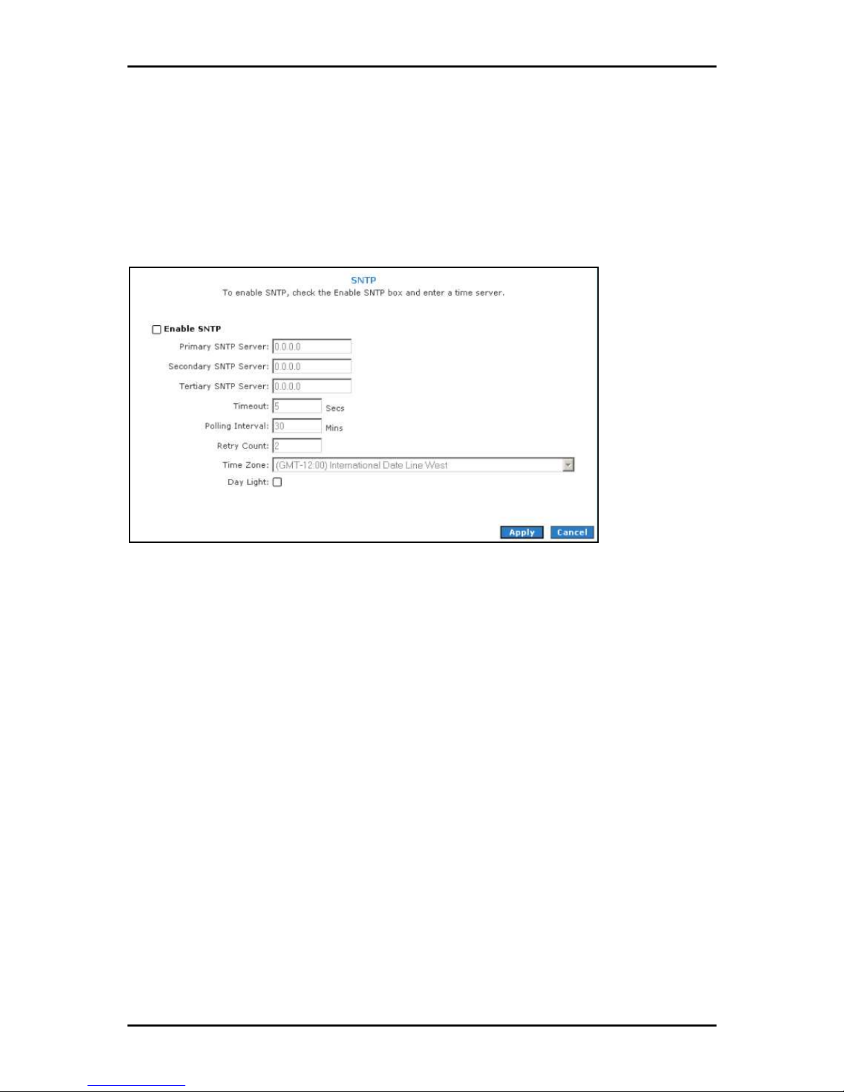
Simple Network Timing Protocol
Simple network timing protocol (SNTP) is a protocol used to synchronize the system time
to the public SNTP servers. It uses the UDP protocol on port 123 to communicate between
clients and servers.
SNTP
SNTP
SNTPSNTP
To enable SNTP:
1. Check Enable SNTP
Enable SNTP.
Enable SNTPEnable SNTP
2. Configure the following fields:
Primary SNTP Server
Primary SNTP Server The IP address or the host name of the primary SNTP
Primary SNTP Server Primary SNTP Server
server. This can be provided by ISP or defined by user.
Secondary SNTP Server
Secondary SNTP Server The IP address or the host name of the secondary
Secondary SNTP Server Secondary SNTP Server
SNTP server. This can be provided by ISP or defined by user.
Tertiary SNTP Server
Tertiary SNTP Server The IP address or the host name of the tertiary SNTP
Tertiary SNTP Server Tertiary SNTP Server
server. This can be provided by ISP or defined by user.
Timeout
Timeout If the router failed to connect to an SNTP server within the
Timeout Timeout
Timeout period, it retries the connection.
Page 58 of 129
Page 59

Polling Interval
Polling Interval The amount of time between a successful connection with
Polling Interval Polling Interval
a SNTP server and a new attempt to connect to an SNTP server.
Retry Count
Retry Count The number of times the router tries to connect to an SNTP
Retry Count Retry Count
server before it tries to connect to the next server in line.
Time Zone
Time Zone The time zone in which the router resides.
Time Zone Time Zone
Day Light
Day Light Select this option to enable/disable daylight saving time (DST).
Day Light Day Light
DST is not automatically enabled or disabled. You need to manually enable
and disable it.
User Manual
3. Click Apply
4. To make changes permanent, click Save Settings
Apply to temporarily apply the settings.
Apply Apply
Save Settings.
Save SettingsSave Settings
Page 59 of 129
Page 60

User Manual
Simple Network Management Protocol
SNMP (Simple Network Management Protocol) is a troubleshooting and management
protocol, which uses the UDP protocol on port 161 to communicate between clients and
servers. SNMP uses a manager MIB (management information base) agent solution to
fulfill the network management needs. The agent is a separate station that can request
data from an SNMP agent in each of the different system in the network. The agent uses
MIBs as dictionaries of manageable objects. Each SNMP-managed device has at least one
agent that can respond to the queries from the NMS. The SNMP agent supports GETS,
SETS, and TRAPS for 4 groups with MIB-II: System, Interface, IP, and ICMP. The SNMP
agent supports three-community names authentication.
SNMP Management
SNMP Management
SNMP Management SNMP Management
To access SNMP:
1. Select the Advanced Menu
2. Select Application > SNMP
Page 60 of 129
Advanced Menu.
Advanced MenuAdvanced Menu
Application > SNMP.
Application > SNMPApplication > SNMP
Page 61

User Manual
IGMP Proxy
IP hosts use Internet group management protocol (IGMP) to report their multicast group
memberships to neighboring routers. Similarly, multicast routers use IGMP to discover
which of their hosts belong to multicast groups. Your router supports IGMP proxy that
handles IGMP messages. When enabled, your router acts as a proxy for a LAN host
making requests to join and leave multicast groups, or a multicast router sending
multicast packets to multicast groups on the WAN side.
IGMP Proxy
IGMP Proxy
IGMP ProxyIGMP Proxy
Multicasting is a form of limited broadcast. UDP is used to send datagram’s to all hosts
that belong to what is called a Host Group. A host group is a set of one or more hosts
identified by a single IP destination address. The following statements apply to host
groups:
Anyone can join or leave a host group at will.
There are no restrictions on a host’s location.
There are no restrictions on the number of members that may belong to a host
group.
A host may belong to multiple host groups.
Non-group members may send UDP datagram’s to the host group.
Page 61 of 129
Page 62

User Manual
Multicasting is useful when the same data needs to be sent to more than one device. For
instance, if one device is responsible for acquiring data that many other devices need,
then multicasting is a natural fit. Note that using multicasting as opposed to sending the
same data to individual devices uses less network bandwidth. The multicast feature also
enables you to receive multicast video streams from multicast servers.
The IGMP Proxy page allows you to enable multicast on available WAN and LAN
connections. You can configure the WAN or LAN interface as one of the following:
Upstream
Upstream The interface that IGMP requests from hosts are sent to the multicast
UpstreamUpstream
router.
Downstream
Downstream The interface data from the multicast router are sent to hosts in the
DownstreamDownstream
multicast group database.
Ignore
Ignore No IGMP request nor data multicast are forwarded.
IgnoreIgnore
You can perform one of the two options:
1. Configure one or more WAN interface as the upstream interface.
2. Configure one or more LAN interface as the upstream interface.
To configure the IGMP Proxy:
1. Select Advanced
2. Select Application > IGMP Proxy
Advanced.
AdvancedAdvanced
Application > IGMP Proxy.
Application > IGMP ProxyApplication > IGMP Proxy
3. Configure the following interfaces:
Quickstart
LAN group 1
4. Click Apply
Apply to temporarily apply the settings.
ApplyApply
5. To make changes permanent, click Save Settings
Page 62 of 129
Save Settings.
Save SettingsSave Settings
Page 63

User Manual
TR-068 WAN Access
The TR-068 WAN Access page enables you to give temporary permission to someone
(such as technical support staff) to be able to access your router from the WAN side.
From the moment the account is enabled the user is expected to log in within 20
minutes, otherwise the account expires. Once the user has logged in, if the session
remains inactive for more than 20 minutes, the user will be logged out and the account
expires.
Enable WAN Access Update
Enable WAN Access Update
Enable WAN Access UpdateEnable WAN Access Update
To create a temporary user account for remote access:
1. Select the Advanced Menu
2. Select Application > TR
3. Select WAN Update
4. Select WAN Access
5. Enter a user name and password in the User Name
Advanced Menu.
Advanced MenuAdvanced Menu
Application > TR----068
Application > TRApplication > TR
WAN Update.
WAN UpdateWAN Update
WAN Access.
WAN AccessWAN Access
068 WAN Access
068 068
WAN Access.
WAN AccessWAN Access
User Name and Password
User Name User Name
6. Enter a port number In the Port field (for example, 51003).
To access your router remotely, enter the following URL:
http(s)://10.10.10.5:51003
Password fields.
Password Password
Page 63 of 129
Page 64
User Manual
Syntax
Syntax: http(s)://WAN IP of router:Port Number
SyntaxSyntax
7. Click Apply
8. To make changes permanent, click Save Settings
Apply to temporarily apply the settings.
Apply Apply
Save Settings.
Save SettingsSave Settings
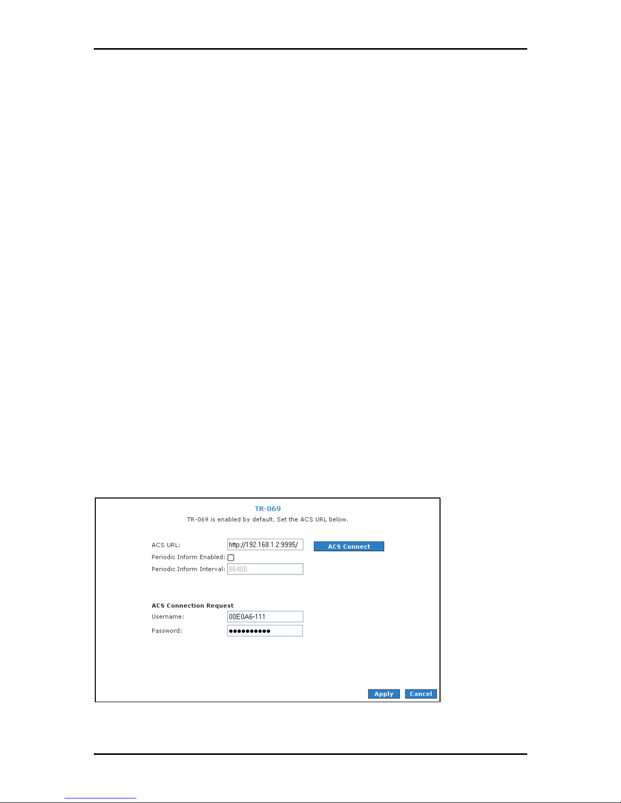
TR-069
The TR-069 page allows you to set up connection parameters that cannot be seen by end
users. TR-069 is CPE Management Protocol from WAN side, intended for communication
between a CPE and Auto-Configuration Server (ACS). The CPE WAN Management Protocol
defines a mechanism that encompasses secure auto-configuration of a CPE, and also
incorporates other CPE management functions into a common framework.
The CPE WAN Management Protocol is intended to support a variety of functionalities to
manage a collection of CPE, including the following primary capabilities:
Auto-configuration and dynamic service provisioning
Software/firmware image management
Status and performance monitoring
Diagnostics
TR
TR----069
069
TRTR
069069
Page 64 of 129
Page 65

To set TR-069:
User Manual
1. Select the Advanced Menu
2. Select Application > TR
Advanced Menu.
Advanced MenuAdvanced Menu
Application > TR----069
Application > TRApplication > TR
069.
069069
3. Leave ACS URL.
4. Select Periodic Inform Enabled
Periodic Inform Enabled and then enter the Periodic Inform Interval
Periodic Inform Enabled Periodic Inform Enabled
Periodic Inform Interval.
Periodic Inform IntervalPeriodic Inform Interval
5. Click ACS Connect to connect to the ACS. When a connection is established, the
AVS updates the ACS URL
6. To temporarily apply the settings, click Apply
7. To make changes permanent, click Save Settings
ACS URL, Periodic Inform Enabled
ACS URLACS URL
Periodic Inform Enabled, and Periodic Inform Interval
Periodic Inform EnabledPeriodic Inform Enabled
Apply.
ApplyApply
Save Settings.
Save SettingsSave Settings
Periodic Inform Interval.
Periodic Inform IntervalPeriodic Inform Interval
Page 65 of 129
Page 66
User Manual
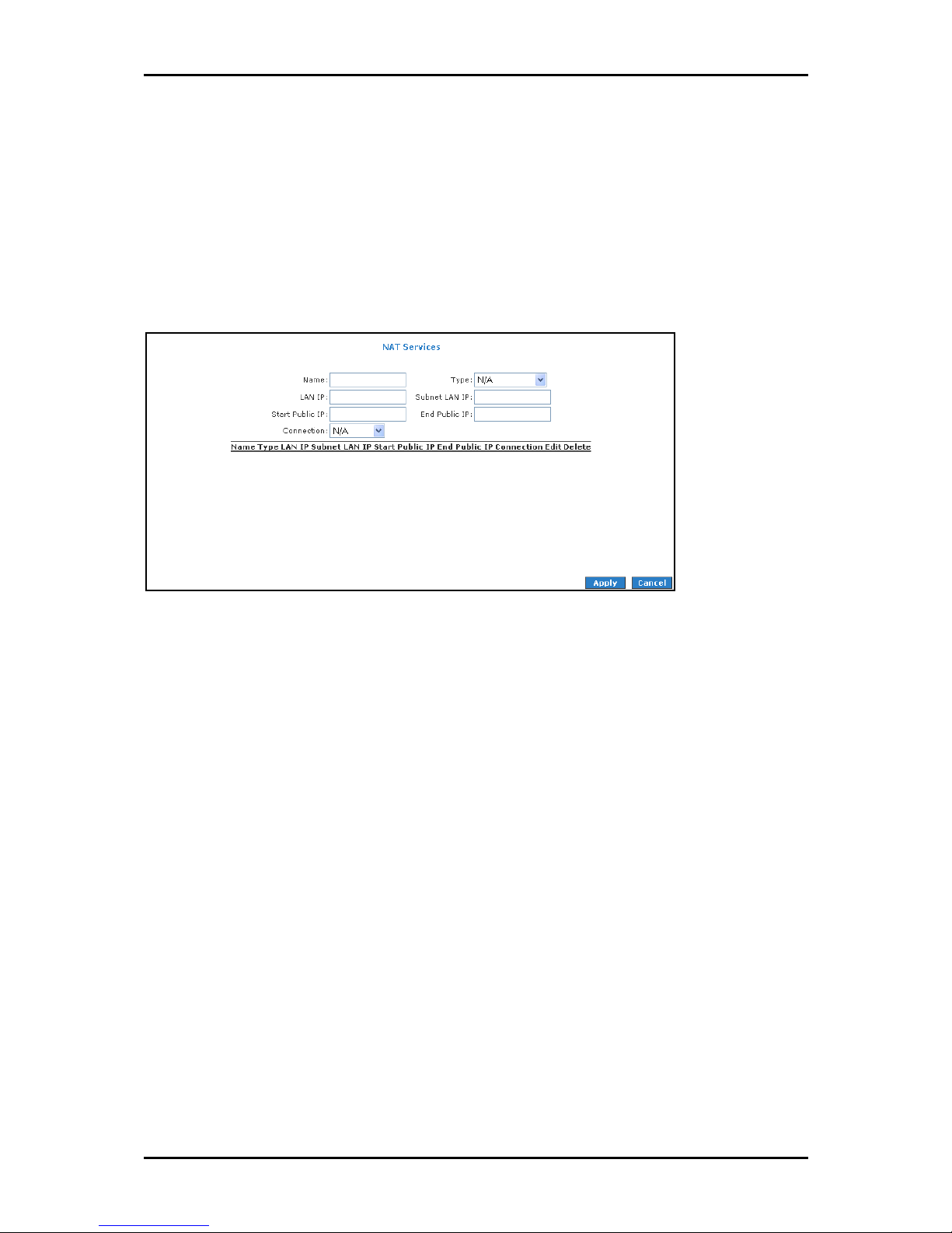
NAT Services
If the user has more than one public IP address assigned by the ISP, these additional IP
addresses can be used to map to servers on the LAN. One public IP address will be used
to provide Internet access to the LAN computers via NAT, serving as the primary IP
address of the router. The rest will be mapped to servers on the LAN.
NAT Services
NAT Services
NAT ServicesNAT Services
To access NAT:
1. Select the Advanced Menu
2. Select Application > NAT Services
Advanced Menu.
Advanced MenuAdvanced Menu
Application > NAT Services.
Application > NAT ServicesApplication > NAT Services
Page 66 of 129
Page 67
User Manual
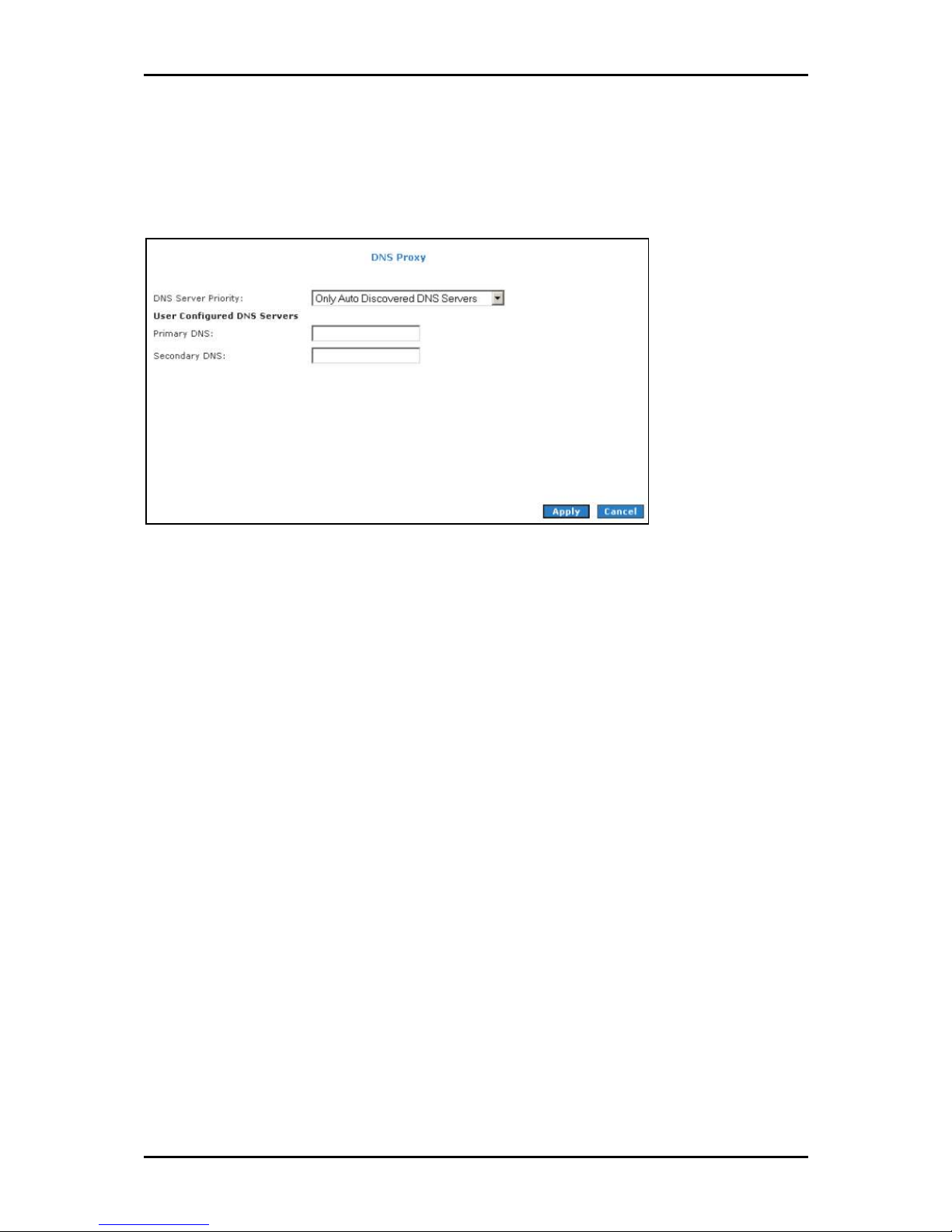
DNS Proxy
DNS Proxy determines the primary Domain Name Server and secondary DNS to be used.
DNS Proxy
DNS Proxy
DNS ProxyDNS Proxy
To select the DNS Server Priority:
1. Select Advanced
2. Select Application > DNS Proxy
3. Select the DNS Server Priority
Advanced.
AdvancedAdvanced
Application > DNS Proxy.
Application > DNS ProxyApplication > DNS Proxy
DNS Server Priority:
DNS Server PriorityDNS Server Priority
Only Auto Discovered DNS Servers
Only User Configured DNS Servers
Auto Discovered then User Configured
User Configured then Auto Discovered
4. Click Apply
Apply to temporarily apply settings.
Apply Apply
5. To make changes permanent, click Save Settings
Save Settings.
Save SettingsSave Settings
Page 67 of 129
Page 68

User Manual
Dynamic DNS Client
Dynamic DNS allows the user to register with a Dynamic DNS Provider. The Dynamic DNS
will be linked with the WAN IP of the router even after the ISP update the WAN IP to
another IP address. It can be useful in web hosting and FTP services.
Dynamic DNS Client
Dynamic DNS Client
Dynamic DNS ClientDynamic DNS Client
Note:
Note: The User Name/Password entered should be similar to the User Name/Password you have
Note:Note:
specified during the registration of the DNS hostname.
To enable Dynamic DNS:
1. Select Advanced
2. Select Application > Dynamic DNS Client
Advanced.
AdvancedAdvanced
Application > Dynamic DNS Client.
Application > Dynamic DNS ClientApplication > Dynamic DNS Client
3. Configure the following fields:
Connection
DDNS Server
DDNS Client
User Name
Password
Page 68 of 129
Page 69

Domain Name
User Manual
4. Click Apply
5. To make changes permanent, click Save Settings
Apply to temporarily apply the settings.
Apply Apply
Settings.
SettingsSettings
Easy Connect Configuration
Easy Connect feature allow user to surf web with ease without the need to changes
default configuration setting, i.e. TCP/IP, Proxy, DNS of user’s computer.
Easy Connect Confi
Easy Connect Configuration
Easy Connect ConfiEasy Connect Confi
guration
gurationguration
Easy Connect features include:
Auto IP
Auto IP All valid TCP/IP setting on user’s computer can surf web via the router
Auto IPAuto IP
without the need to change the IP address
Auto DNS
Auto DNS Any DNS IP address set at user’s computer irregardless whether the
Auto DNSAuto DNS
address is valid or invalid DNS, Auto DNS still allow user’s computer to surf the
web.
Auto NetBIOS
Auto NetBIOS It allows proxy server to use any NetBIOS name which the Auto
Auto NetBIOSAuto NetBIOS
NetBIOS still allow computer to surf the web with a condition that the router
gateway MUST be in Private IP Ranges.
Page 69 of 129
Page 70

User Manual
Auto Proxy
Auto Proxy Refers to any valid Private IP proxy setting with any port number. For
Auto ProxyAuto Proxy
example, when you enter 1234 on the browser, Auto Proxy will still allow the
computer to surf the web. Any Public IP proxy setting will assume the proxy is
valid and hence Auto Proxy function will not take place.
Note:
Note: The port number to be used must be specified in both the browser and the Auto Proxy Ports.
Note:Note:
Private IP Ranges
Class A: 10.0.0.0 ~ 10.255.255.255
Class B: 172.16.0.0 ~ 172.31.255.255
Class C: 192.168.0.0 ~ 192.168.255.255
To access Easy Connect:
1. Select Advanced Menu
2. Select Application > Easy Connect Configuration
Advanced Menu.
Advanced MenuAdvanced Menu
Application > Easy Connect Configuration.
Application > Easy Connect ConfigurationApplication > Easy Connect Configuration
Page 70 of 129
Page 71

User Manual
Port Triggering
Port triggering is a specialized form of port forwarding which enables computers behind
NAT to be accessed. It triggers open an incoming port when a client on the LAN makes an
outgoing connection to a predetermined port on a server.
Port Triggering
Port Triggering
Port TriggeringPort Triggering
To access port triggering:
1. Select Advanced Menu
2. Select Application > Port Triggering
Advanced Menu.
Advanced MenuAdvanced Menu
Application > Port Triggering.
Application > Port TriggeringApplication > Port Triggering
Page 71 of 129
Page 72

User Manual
Port Forwarding
Port forwarding (or virtual server) allows you to direct incoming traffic to specific LAN
hosts based on a protocol port number and protocol. Using the Port Forwarding page, you
can provide local services (for example, web hosting) for people on the Internet or play
Internet games. Port forwarding is configurable per LAN group.
Port Forwarding
Port Forwarding
Port ForwardingPort Forwarding
A database of predefined port forwarding rules allows you to apply one or more rules to
one or more members of a defined LAN group. You can view the rules associated with a
predefined category and add the available rules for a given category. You can also
create, edit, or delete your own port forwarding rules.
To configure port forwarding:
1. Select Advanced
2. Select Application > Port Forwarding
3. Select WAN Connection
available in the LAN IP
page
page, which is accessed by clicking New IP
pagepage
Advanced.
AdvancedAdvanced
Application > Port Forwarding.
Application > Port ForwardingApplication > Port Forwarding
WAN Connection, LAN Group
WAN ConnectionWAN Connection
LAN IP drop-down menu, you can add it using the LAN Client
LAN IP LAN IP
LAN Group, and LAN IP
LAN GroupLAN Group
New IP.
New IPNew IP
LAN IP. If the desired LAN IP is not
LAN IPLAN IP
LAN Client
LAN Client LAN Client
Page 72 of 129
Page 73

User Manual
4. Select the available rules for a given category and click Add
this category. If a rule is not in the list, you can create your own rule in the User
category. Select User
User, and then click New
UserUser
New.
NewNew
5. The Rule Management page opens for you to create new rules. Enter Rule Name
Protocol
Protocol, Port Start
ProtocolProtocol
Port Start, Port End
Port StartPort Start
Port End, and Port Map
Port EndPort End
Port Map, and then click Apply
Port MapPort Map
Add to apply the rule for
AddAdd
User
User User
Rule Name,
Rule NameRule Name
Apply.
ApplyApply
6. Continue to add rules as they apply from each category.
7. Click Apply
8. To make changes permanent, click Save Settings
Apply to temporarily activate the settings.
Apply Apply
Save Settings.
Save SettingsSave Settings
DMZ Settings
Setting a host on your local network as demilitarized zone (DMZ) forwards any network
traffic that is not redirected to another host via the port forwarding feature to the IP
address of the host. This opens the access to the DMZ host from the Internet. This
function is disabled by default. By enabling DMZ, you add an extra layer of security
protection for hosts behind the firewall.
To enable DMZ Settings:
1. On the Port Forwarding
Port Forwarding page, select Enable DMZ
Port Forwarding Port Forwarding
Enable DMZ. This opens the DMZ Settings
Enable DMZEnable DMZ
page.
2. Select the WAN Connection
3. Click Apply
4. To make changes permanent, click Save Settings
WAN Connection, LAN Group
WAN ConnectionWAN Connection
Apply to temporarily apply the settings.
Apply Apply
LAN Group, and LAN IP Address
LAN GroupLAN Group
Save Settings.
Save SettingsSave Settings
LAN IP Address.
LAN IP AddressLAN IP Address
Custom Port Forwarding
The Custom Port Forwarding page allows you to create up to 15 custom port forwarding
entries to support specific services or applications, such as concurrent NAT/NAPT
operation.
Page 73 of 129
Page 74

User Manual
Bridge Filters
The Bridge Filters allows you to enable, add, edit, or delete the filter rules. When bridge
filtering is enabled, each frame is examined against every defined filter rule in sequence.
When a match is found, the appropriate filtering action (allow or deny) is performed. Up
to 20 filter rules are supported with bridge filtering.
Bridge Filters
Bridge Filters
Bridge FiltersBridge Filters
To configure Bridge Filters:
1. Select Advanced
2. Select Application > Bridge Filters
3. Select Enable Bridge Filters
4. To add a rule, enter the source MAC address
Protocol
Protocol with desired filtering type, then click Add
Protocol Protocol
Note:
Note: You can also edit a rule that you created using the Edit
Note:Note:
Advanced.
AdvancedAdvanced
Application > Bridge Filters. This opens the Bridge Filters page.
Application > Bridge FiltersApplication > Bridge Filters
Enable Bridge Filters.
Enable Bridge FiltersEnable Bridge Filters
MAC address, Destination MAC address
MAC addressMAC address
5. Click Apply
6. To make changes permanent, click Save Settings
Apply to temporarily activate the settings.
Apply Apply
Save Settings.
Save SettingsSave Settings
Destination MAC address, and
Destination MAC addressDestination MAC address
Add.
AddAdd
Edit checkbox. You can delete using Delete
Edit Edit
Delete.
DeleteDelete
Page 74 of 129
Page 75

User Manual
Web Access Control
The Web Access Control page allows you to access the router via the web from a remote
location like your home or office.
Web Access Control
Web Access Control
Web Access ControlWeb Access Control
To configure Web Access:
1. Select Advanced Menu
2. Select Application > Web Access Control
3. Select Enable
4. Select the connection used in Choose a connection
Advanced Menu.
Advanced MenuAdvanced Menu
Application > Web Access Control.
Application > Web Access ControlApplication > Web Access Control
Enable.
EnableEnable
Choose a connection.
Choose a connectionChoose a connection
5. Configure the following fields:
Remote Host IP
Remote Netmask
Redirect Port
6. Click Apply
Apply to temporarily activate the settings on the page. The WAN address is
Apply Apply
now added into the IP Access List. This allows you to access you router remotely.
7. To make changes permanent, click Save Settings
Save Settings.
Save SettingsSave Settings
Page 75 of 129
Page 76

User Manual
SSH Access Control
SSH Access control allows you to access the router remotely via SSH from the WAN side.
SSH Acc
SSH Access Control
SSH AccSSH Acc
To configure SSH Access Control:
ess Control
ess Controless Control
1. Select Advanced
2. Select Application > SSH Access Control
3. Select Enable
4. Enter the IP address of the remote computer you want to use in Remote Host IP
5. Enter the Remo
6. To temporarily implement the settings, click Apply
7. To make changes permanent, click Save Settings
Advanced Menu.
AdvancedAdvanced
Application > SSH Access Control. This opens the SSH Access Control
Application > SSH Access ControlApplication > SSH Access Control
Enable.
EnableEnable
Remote Netmask
te Netmask.
RemoRemo
te Netmaskte Netmask
Apply.
ApplyApply
Save Settings.
Save SettingsSave Settings
SSH Access Control page.
SSH Access Control SSH Access Control
Remote Host IP.
Remote Host IPRemote Host IP
Page 76 of 129
Page 77

User Manual
Quality of Service
Quality of service allows network administrators to configure the routers to meet the real
time requirements for voice and video.
Different networks use different QoS markings like:
ToS network: ToS bits in the IP header
VLAN network: priority bits in the VLAN header
DSCP network: uses only 5 bits of the CoS
WLAN: WLAN QoS header.
The QoS framework is supported on all the above domains. How do you make them talk
to each other? How can you make sure the priority from one network is carried over to
another network? Class of service (CoS) is introduced as the common language for the
QoS mappings. When QoS is enabled, the router has full control over packets from the
time they enter the router till they leave the router. This is how it works: The domain
mapping (ToS bits, priority bits, etc.) of a packet needs to be translated to CoS when the
packet enter the router, and vice versa, the CoS of a packet needs to be translated back
to the domain mapping when the packet leaves the router.
There are 6 types of CoS (in descending priority):
CoS1
CoS2
CoS3
CoS4
CoS5
CoS6
Page 77 of 129
Page 78

User Manual
The rules are:
1. CoS1 has absolute priority and is used for expedited forwarding (EF) traffic. This is
always serviced till completion.
2. CoS2-CoS5 are used for assured forwarding (AF) classes. They are serviced in a
strict round robin manner using the following priority scheme:
CoS2 > CoS3 > CoS4 > CoS5
3. CoS6 is for best effort (BE) traffic. This is only serviced when there is no other class
of service. If QoS is not enabled on your router, all traffic will be treated as best
effort.
There are some additional terms you should get familiarize with:
Ingress: Packets arriving from a WAN/LAN interface into the router.
Egress: Packets sent from the router to a WAN/LAN interface.
Trusted mode: Honors the domain mapping (ToS byte, WME, WLAN user priority).
Untrusted mode: Does not honor domain mapping. This is the default QoS setting.
Traffic Conditioning Agreement (TCA): The TCA needs to be defined for each
interface:
o
Ingress mappings (Domain =>CoS)
o Egress Mappings (CoS => Domain)
o
Untrusted mode (default)
Shaper
Page 78 of 129
Page 79

User Manual
Egress
For packets going out of the router, the markings (CoS) need to be translated to the
mappings understood by the network domains. The reverse CoS and domain mapping is
configured using the Egress. To access Egress
QoS > Egress
QoS > Egress.
QoS > EgressQoS > Egress
Egress, select the Advanced Menu
EgressEgress
Advanced Menu and then select
Advanced Menu Advanced Menu
There are three Egress modes:
No Egress mode
Layer 2
Layer 3
No Egress Mode
The default Egress page setting for all interfaces is No Egress. In this mode, the domain
mappings of the packets are untouched.
Egress
Egress
EgressEgress
Page 79 of 129
Page 80

User Manual
Layer 2
The Egress Layer 2 page allows you to map the CoS of an outgoing packet to user priority
bits, which is honored by the VLAN network. Again, this feature is only configurable on
the WAN interfaces as VLAN is only supported on the WAN side in the current release.
Layer 2
Layer 2
Layer 2Layer 2
Field
Field Description
FieldField
Interface Select the WAN interface to configure the QoS for outgoing packets; LAN interface
Unclassified
Packet
Class of Service The selections are (in the order of descending priority): CoS1, CoS2, CoS3, CoS4, CoS5,
User Priority The selections are 0, 1, 2, 3, 4, 5, 6, 7.
Description
DescriptionDescription
cannot be selected as VLAN is currently supported on the WAN side only.
Some locally generated packets might not have been classified and thus do not have
a CoS value, such as PPP control packet and ARP packet. You can define the CoS for
all unclassified outgoing packets on layer 2 using this field, which will then pick up
the user priority bits based on the mapping rules you create. The selections are (in
the order of descending priority): CoS1, CoS2, CoS3, CoS4, CoS5, and CoS6. The
default value is CoS1 (recommended).
and CoS6.
Page 80 of 129
Page 81
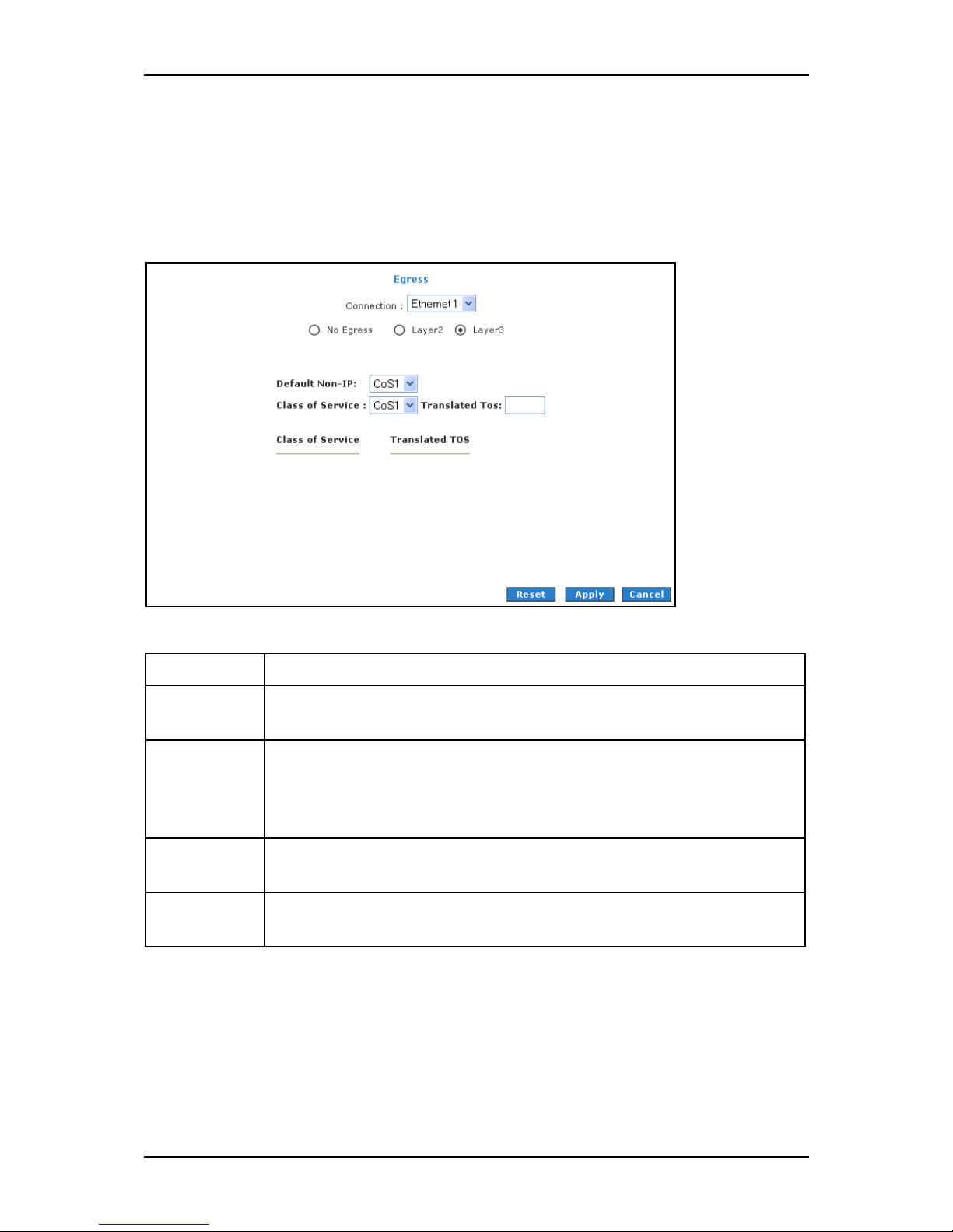
User Manual
Layer 3
Egress Layer 3 enables you to map CoS to ToS so that the priority marking of outgoing
packets can be carried over to the IP network.
Layer 3
Layer 3
Layer 3Layer 3
Field
Field Description
FieldField
Interface Select the WAN interface to configure the QoS for outgoing packets, LAN interface
Default Non-IP Locally generated packets (such as ARP packets) do not have a CoS marking. You can
Class of Service The selections are (in the order of descending priority): CoS1, CoS2, CoS3, CoS4, CoS5,
Translated TOS The Type of Service field takes values from 1 to 255. The selections are 0, 1, 2, 3, 4,
Description
DescriptionDescription
cannot be selected as VLAN is currently supported on the WAN side only.
define the CoS for all unclassified outgoing packets on layer 3 using this field. The
selections are in the order of descending priority): CoS1, CoS2, CoS3, CoS4, CoS5, and
CoS6. The default value is CoS1 (recommended).
and CoS6.
5, 6, 7.
Page 81 of 129
Page 82

User Manual
Ingress
Ingress enables you to configure QoS for packets as soon as they come into the router.
The domain mappings are converted to CoS (the common language) so that the priority
marking is carried over.
There are four Ingress modes:
Untrusted mode
Layer 2
Layer 3
Static
Untrusted Mode
Untrusted is the default Ingress page setting for all interfaces. In this mode, no domain
mapping is honored in the router. All packets are treated as CoS6 (best effort).
Untrusted mode
Untrusted mode
Untrusted modeUntrusted mode
Page 82 of 129
Page 83

User Manual
Layer 2
Layer 2 allows you to map an incoming packet with VLAN priority to CoS. This feature is
only configurable on the WAN interfaces as VLAN is only supported on the WAN side in
the current software release.
Layer 2
Layer 2
Layer 2Layer 2
Field
Field Description
FieldField
Interface Select the WAN interface here to configure the CoS for incoming traffic. Only WAN
Class of Service The selections are (in the order of descending priority): CoS1, CoS2, CoS3, CoS4, CoS5,
User Priority The selections are 0, 1, 2, 3, 4, 5, 6, 7.
Description
DescriptionDescription
interface can be selected as VLAN is currently supported only on the WAN side.
and CoS6.
To configure Ingress Layer 2:
1. Select Advanced Menu
2. Select QoS > Ingress
3. Select the quickstart
4. Select Layer 2
Advanced Menu.
Advanced MenuAdvanced Menu
QoS > Ingress.
QoS > IngressQoS > Ingress
quickstart interface.
quickstart quickstart
Layer 2.
Layer 2Layer 2
Page 83 of 129
Page 84

User Manual
5. Select CoS1
CoS1 in Class of Service
CoS1CoS1
Class of Service and enter 5555 in Priority Bits
Class of Service Class of Service
Priority Bits. Any packet with priority
Priority BitsPriority Bits
marking 5 is mapped to CoS1, the highest priority that is normally given to the
voice packets.
6. Click Apply
7. Select CoS2
Apply to temporarily the settings.
Apply Apply
CoS2 in the Class of Service
CoS2 CoS2
Class of Service and 1111 in Priority Bits
Class of ServiceClass of Service
Priority Bits. Any packet that has a
Priority BitsPriority Bits
priority bit of 1 is mapped to CoS2, which is the second highest priority. This is
given to the high priority packets such as video.
8. Click Apply
Apply to temporarily activate the settings.
Apply Apply
9. Repeat steps 5-7 to add more rules. Up to eight rules can be configured for each
interface.
10. To make changes permanent, click Save Settings
Notes:
Notes:
Notes:Notes:
Any priority bits that have not been mapped to a CoS default to CoS6, the lowest
priority.
Any WAN interface that is not configured has the default Untrusted mode.
Save Settings.
Save SettingsSave Settings
Page 84 of 129
Page 85

User Manual
Layer 3
The Layer 3 page allows you to map ToS bits of incoming packets from the IP network to
CoS for each WAN/LAN interface.
Layer 3
Layer 3
Layer 3Layer 3
Field
Field Description
FieldField
Interface For both WAN and LAN interfaces, you can configure QoS for layer 3 (IP) data traffic.
Class of Service This CoS field allows you to map incoming layer 3 WAN/LAN packets to one of the
ToS The Type of Service field takes values from 0 to 255.
Default Non-IP A static CoS can be assigned to all layer 3 incoming packets (per interface) that do
Description
DescriptionDescription
following CoS (in the order of descending priority): CoS1, CoS2, CoS3, CoS4, CoS5, and
CoS6.
not have an IP header, such as PPP control packets and ARP packets. The default is
CoS1 (recommended).
To configure Ingress Layer 3:
1. Select Advanced Menu
2. Select QoS > Ingress
Advanced Menu.
Advanced MenuAdvanced Menu
QoS > Ingress.
QoS > IngressQoS > Ingress
3. Select the quickstart
4. Select Layer 3
quickstart interface.
quickstart quickstart
Layer 3.
Layer 3Layer 3
Page 85 of 129
Page 86

User Manual
5. Select CoS1
CoS1 in Class of Service
CoS1 CoS1
Class of Service and enter 22
Class of ServiceClass of Service
22 in Type of Service
Type of Service (ToS). Any incoming
2222
Type of ServiceType of Service
packet from LAN Group 1 (layer 3) with a ToS of 22 is mapped to CoS1, the
highest priority, which is normally given to the voice packets.
6. Leave the default value CoS1 in Default Non-IP. Any incoming packet from LAN
Group 1 without an IP is mapped to CoS1, the highest priority.
7. Click Apply
Apply to temporarily activate the settings.
ApplyApply
8. Repeat step 5-7 to add more rules to LAN Group 1. Up to 255 rules can be
configured for each interface.
9. To make changes permanent, click Save Settings
Notes:
Notes: Any priority bits that have not been mapped to a CoS default to CoS6, the lowest
Notes:Notes:
priority.
Any WAN interface that is not configured has the default Untrusted mode.
Save Settings.
Save SettingsSave Settings
Page 86 of 129
Page 87

User Manual
Static
The Ingress - Static page enables you to configure a static CoS for all packets received on
a WAN or LAN interface.
Static
Static
StaticStatic
To configure Ingress Layer 3:
1. Select Adv
2. Select QoS > Ingress
3. Select the quickstart
4. Select Static
Advanced Menu
anced Menu.
AdvAdv
anced Menuanced Menu
QoS > Ingress.
QoS > IngressQoS > Ingress
quickstart interface.
quickstart quickstart
Static.
StaticStatic
5. At the ETHERNET Interface. You are configuring QoS on this interface only. Any
WAN/LAN interface that is not configured has the default Untrusted mode.
6. Select CoS1
receives CoS1
7. Click Apply
CoS1 in Class o
CoS1 CoS1
CoS1, the highest priority.
CoS1CoS1
Apply to temporarily activate the settings.
Apply Apply
Class of Service
Class oClass o
f Service. All incoming traffic from the ETHERNET interface
f Servicef Service
8. To make changes permanent, click Save Settings
Save Settings.
Save SettingsSave Settings
Page 87 of 129
Page 88

User Manual
QoS Shaper Configuration
The Shaper Configuration page is accessed by selecting Shaper on the Advanced main
page. Three shaper algorithms are supported:
HTB
Low Latency Queue Discipline
PRIOWRR
QoS Shaper Configuration
QoS Shaper Configuration
QoS Shaper ConfigurationQoS Shaper Configuration
Note:
Note: Egress TCA is required if shaper is configured for that interface.
Note:Note:
Field
Field Description
FieldField
Interface The selections are WAN/LAN interfaces except WLAN, which does not support Shaper
Max Rate This field is applicable for the HTB Queue Discipline and Low Latency Queue
HTB Queue
Discipline
Page 88 of 129
Description
DescriptionDescription
feature. This field needs to be selected before shaper configuration.
Discipline, both are rate-based shaping algorithms.
The hierarchical token bucket queue discipline is a rate-based shaping algorithm. This
algorithm rate shapes the traffic of a class over a specific interface. All CoSx traffic
uses a specific rate to which data will be shaped. For example: If CoS1 is configured
to 100Kbps then even if 300Kbps of CoS1 data is being transmitted to the interface
only 100Kbps will be sent out.
Page 89
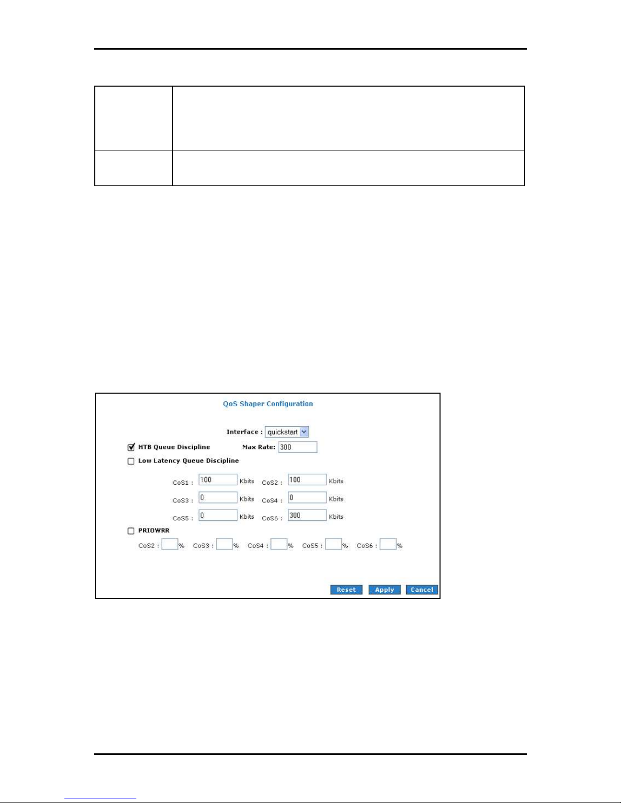
User Manual
Low Latency
Queue Discipline
PRIOWRR This is a priority based weighted round robin algorithm operating on CoS2-CoS6. CoS1
This is similar to the above algorithm except that CoS1 is not rate limited. So in the
example above CoS1 data is not rate limited to 100Kbps but instead all 300Kbps is
transmitted. The side effect is that a misconfigured stream can potentially take all
bandwidth.
queues have the highest priority and are not controlled by the WRR algorithm.
Of the three shaping algorithms available on the Shaper Configuration page, only one can
be enabled at a time. An example of each configuration is given as follows.
Example 1: HTB Queue Discipline Enabled
In the example below, HTB Queue Discipline is enabled. The PPPoE1 connection has a
total of 300 Kbps of bandwidth, of which 100 Kbps is given to CoS1 and another 100 Kbps
is given to CoS2. When there is no CoS1 or CoS2 packets, CoS6 packets have the whole
300 Kbps of bandwidth.
HTB Queue Discipline enabled
HTB Queue Discipline enabled
HTB Queue Discipline enabledHTB Queue Discipline enabled
Page 89 of 129
Page 90
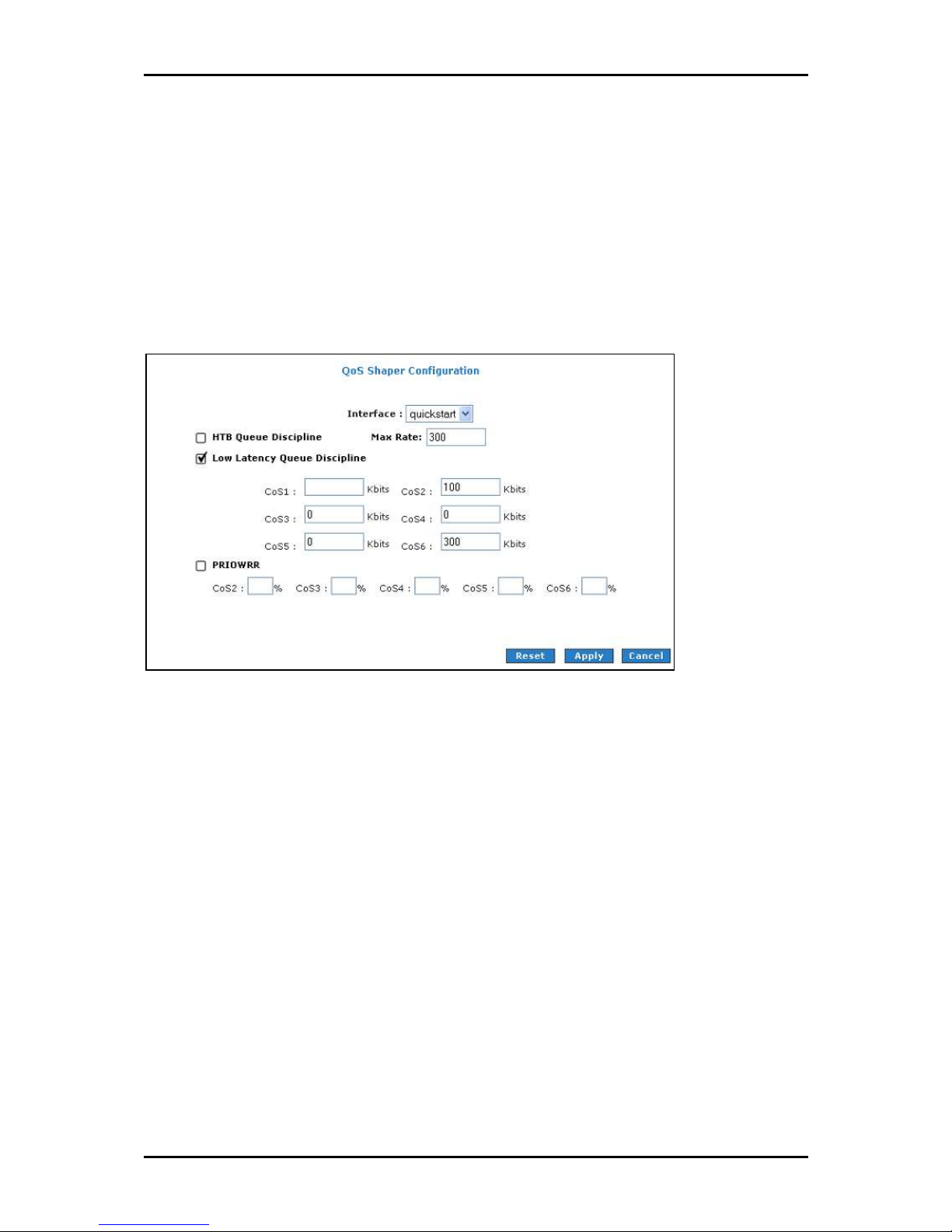
User Manual
Example 2: Low Latency Queue Discipline Enabled
In this second example, Low Latency Queue Discipline is enabled. CoS1 is not rate
controlled (hence the field is disabled). CoS2 takes 100 Kbps when there is no CoS1
packets. CoS6 has 300 Kbps when there is no CoS1 or CoS2 packets. This is similar to the
HTB queue discipline as they are both rate-based algorithm, except that CoS1 is handled
differently.
Low Latency Queue Discipline enabled
Low Latency Queue Discipline enabled
Low Latency Queue Discipline enabledLow Latency Queue Discipline enabled
Page 90 of 129
Page 91
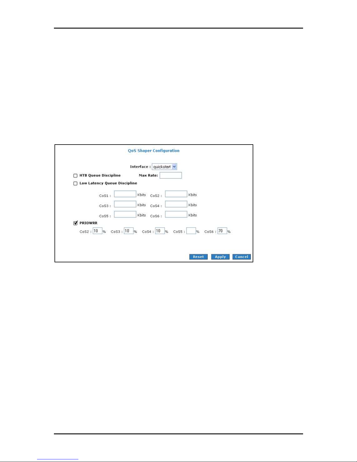
User Manual
Example 3: PRIOWRR Enabled
In this third example, PRIOWRR is enabled. Since PRIOWRR operates only on the number
of packets being transmitted, the max rate field has been disabled. Only percentage can
be assigned to the CoS2 - CoS6. CoS1 is not rate controlled (hence the field is not
displayed). When there is no CoS1 packets, CoS2, CoS3, CoS4 each has 10 percent, and
CoS6 has 70 percent. This is similarly to the Low Latency Queue discipline, except that
one is packet-based, and the other is rate-based.
PRIOWRR enabled
PRIOWRR enabled
PRIOWRR enabledPRIOWRR enabled
Page 91 of 129
Page 92

User Manual
Policy Routing Configuration
The Policy Routing Configuration enables you to configure policy routing and QoS.
Policy Routing Configuration
Policy Routing Configuration
Policy Routing ConfigurationPolicy Routing Configuration
Field
Field Description
FieldField
Ingress Inter
face
Destination
Interface
DiffServ Code
Point
Class of Service The selections are (in the order of priority): CoS1, CoS2, CoS3, CoS4, CoS5, CoS6, and
Source IP The IP address of the traffic source.
Mask The source IP Netmask. This field is required if the source IP has been entered.
Destination IP The IP address of the traffic destination.
Description
DescriptionDescription
The incoming traffic interface for a Policy Routing rule. Selections include LAN
interfaces, WAN interfaces, Locally generated (traffic), and not applicable. Examples
of Locally generated traffic are: voice packets, packets generated by applications
such as DNS, DHCP, etc.
The outgoing traffic interfaces for a Policy Routing rule. Selections include LAN
Interfaces and WAN interfaces.
The diffServ code point (DSCP) field value ranges from 1 to 255. This field cannot be
configured alone, additional fields like IP, Source MAC, and/or Ingress Interface
should be configured.
N/A.
Mask The Netmask of the destination. This field is required if the destination IP has been
entered.
Page 92 of 129
Page 93

User Manual
Protocol The selections are TCP, UDP, ICMP, Specify, and none. If you choose Specify, you need
to enter the protocol number in the box next to the Protocol field. This field cannot
be configured alone, additional fields like IP, Source MAC, and/or Ingress Interface
should be configured. This field is also required if the source port or destination port
has been entered.
Source Port The source protocol port. You cannot configure this field without entering the
protocol first.
Destination Port The destination protocol port or port range. You cannot configure this field without
entering the protocol first.
Source MAC The MAC address of the traffic source.
Local Routing
MAC
This field is enabled only when Locally Generated is selected in the Ingress Interface
field. The mark for DNS traffic generated by different applications are described
below:
Dynamic DNS: 0xE1
Dynamic Proxy: 0xE2
Web Server: 0xE3
MSNTP: 0xE4
DHCP Server: 0xE5
IP tables Utility: 0xE6
PPP Deamon: 0xE7
IP Route: 0xE8
ATM Library: 0xE9
NET Tools: 0xEA
RIP: 0xEB
RIP v2: 0xEC
UPNP: 0xEE
Busybox Utility: 0xEF
Configuration Manager: 0xF0
DropBear Utility: 0xF1
Voice: 0
Currently routing algorithms make decision based on destination address, i.e. only
Destination IP address and subnet mask is supported. The Policy Routing page enables
you to route packets on the basis of various fields in the packet.
Page 93 of 129
Page 94

User Manual
The following fields can be configured for Policy Routing:
Destination IP address/mask
Source IP address/mask
Source MAC address
Protocol (TCP, UDP, ICMP, etc)
Source port
Destination port
Incoming interface
DSCP
Page 94 of 129
Page 95

User Manual
Routing
Static Routing
If the router is connected to more than one network, you may need to set up a static
route between them. A static route is a pre-defined pathway that network information
must travel to reach a specific host or network. You can use static routing to allow
different IP domain users to access the Internet through the router.
Static Routing
Static Routing
Static RoutingStatic Routing
The New Destination IP is the address of the remote LAN network or host to which you
want to assign a static route. Enter the IP address of the host for which you wish to
create a static route here. For a standard Class C IP domain, the network address is the
first three fields of the New Destination IP, while the last field should be 0. The Subnet
Mask identifies which portion of an IP address is the network portion, and which portion
is the host portion. For a full Class C Subnet, the Subnet Mask is 255.255.255.0. The
Gateway IP address should be the IP address of the gateway device that allows for
contact between the Gateway and the remote network or host.
Page 95 of 129
Page 96

User Manual
Dynamic Routing
Dynamic Routing allows the router to automatically adjust to physical changes in the
network. The router, using the RIP protocol, determines the network packets’ route based
on the fewest number of hops between the source and the destination. The RIP protocol
regularly broadcasts routing information to other routers on the network. The Direction
determines the direction that RIP routes will be updated. Selecting In means that the
router will only incorporate received RIP information. Selecting Out means that the router
will only send out RIP information. Selecting both means that the router will incorporate
received RIP information and send out updated RIP information.
Dynamic Routing
Dynamic Routing
Dynamic Routing Dynamic Routing
The protocol is dependent upon the entire network. Most networks support RIP v1. If RIP
v1 is selected, routing data will be sent in RIP v1 format. If RIP v2 is selected, routing
data will be sent in RIP v2 format using subnet broadcasting. If RIP v1 Compatible is
selected, routing data will be sent in RIP v2 format using multicasting.
Page 96 of 129
Page 97

User Manual
Routing Table
Routing Table displays the information used by routers when making packet-forwarding
decisions. Packets are routed according to the packet's destination IP address.
Routing Table
Routing Table
Routing TableRouting Table
Page 97 of 129
Page 98

User Manual
System Password
Anyone who can access the web interface can be considered an Administrator. To restrict
access to the web interface, you need to set the System Password.
To change the System Password:
1. Select Advanced Menu
2. Click System Password
3. Select Enable Authentication
Advanced Menu
Advanced MenuAdvanced Menu
System Password. This opens the System Password
System Password System Password
Enable Authentication.
Enable AuthenticationEnable Authentication
System Password page.
System PasswordSystem Password
4. Enter your password.
5. Reenter your password in the Confirm Password
6. To temporarily implement the settings, click Apply
7. To make changes permanent, click Save Settings
Note:
Note: Remember your account information. If you forget the User Name and System Password, you
Note:Note:
will need to reset the router to its default settings. To reset, press RESET
panel for 10 seconds.
To change the timeout settings:
Confirm Password text box.
Confirm Password Confirm Password
Apply.
ApplyApply
Save Settings.
Save SettingsSave Settings
RESET at the router’s back
RESET RESET
1. Select Advanced Menu
2. Click System Password
3. Select Enable Authentication
Advanced Menu
Advanced MenuAdvanced Menu
System Password.
System PasswordSystem Password
Enable Authentication.
Enable AuthenticationEnable Authentication
4. Enter the number of minutes in the Idle Timeout
5. To temporarily implement the settings, click Apply
6. To make changes permanent, click Save Settings
Page 98 of 129
Idle Timeout text field.
Idle Timeout Idle Timeout
Apply.
ApplyApply
Save Settings.
Save SettingsSave Settings
Page 99

User Manual
Firmware Update
When updating the firmware, make sure you are using the correct file. Once the upgrade
is complete the router will reboot. You will need to log back into the router after the
firmware upgrade is completed.
To update the firmware:
1. Select the Advanced Menu
Firmware Upgrade
Firmware Upgrade page.
Firmware UpgradeFirmware Upgrade
2. Click Browse
3. Click Update Gateway
Browse and then locate the firmware file.
BrowseBrowse
Update Gateway. The update may take a few minutes. Make sure that the
Update GatewayUpdate Gateway
power is not turned off during the update process.
Advanced Menu and then click Firmware Upgrade
Advanced Menu Advanced Menu
Firmware Upgrade. This opens the
Firmware UpgradeFirmware Upgrade
Restore to Default
To reset to the default factory settings, press RESET
the router’s back panel. When you reset, all the firmware updates will be lost.
To access the web interface again, you need to install the router anew.
RESET for 10 seconds. This can be found at
RESETRESET
Page 99 of 129
Page 100
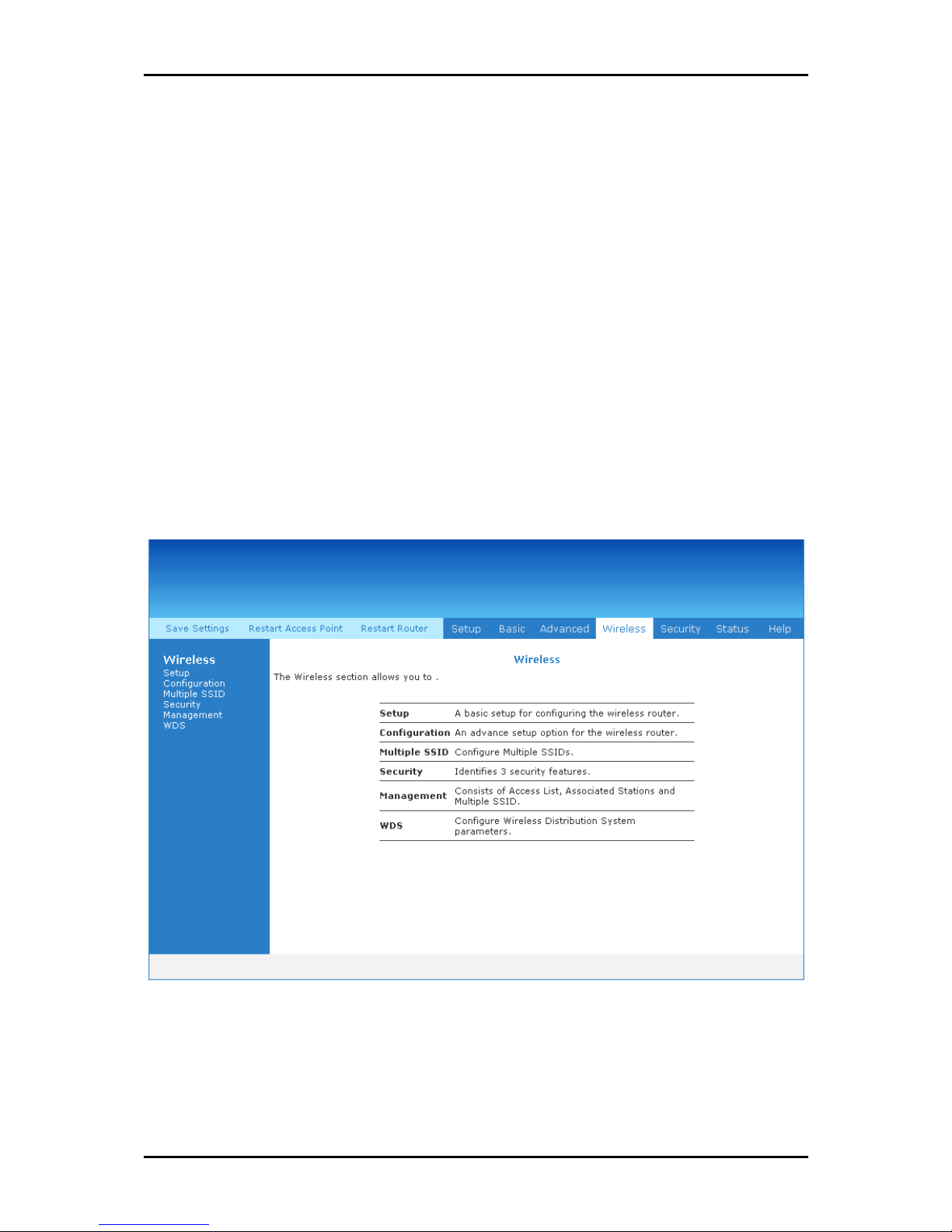
User Manual
Wireless Menu
The Wireless Menu includes the following options:
Setup
Configuration
Multiple SSID
Management
WDS
Wireless Menu
Wireless Menu
Wireless MenuWireless Menu
Page 100 of 129
 Loading...