

Page 1

®
®
www.azodin.com
.68 CALIBER ELECTRONIC PAINTBALL MARKER
OWNERS MANUAL
Page 2

®
SPECIFICATION
1,155 G/ 2.55 LBS/ 40.74 OZ
INTERCHANGEABLE WITH AUTOCOCKER THREAD BARREL
INTERCHANGEABLE WITH ION/ IMPULSE THREAD FEEDNECK
LOW PRESSURE INLINE REGULATOR:
STANDARD ASA THREAD
STANDARD DOVETAIL MOUNT
WEIGHT:
LENGTH:
528 MM/ 20.79 IN
HEIGHT:
240.3 MM/ 9.47 IN
WIDTH:
35 MM/ 1.38 IN
BARREL THREAD:
FEEDNECK THREAD:
ON/ OFF BOTTOM ASA:
Page 3

®
CONTENTS
SAFETY INSTRUCTION AND GUIDELINES
GETTING STARTED
USING THE ZEN BOARD
VELOCITY ADJUSTMENT
REGULATOR ADJUSTMENT
ZERO SYSTEM - INSTRUCTION AND ADJUSTMENT
ASSEMBLY AND CLEANING THE MARKER
REASSEMBLE REAR INTERNALS
TROUBLESHOOTING
ZENITH SCREW CHART
ZENITH O-RING CHART
ZeRO SYSTEM EXPLODED VIEW
INLINE REGULATOR EXPLODED VIEW
ON/OFF BOTTOM ASA EXPLODED VIEW
ZENITH PART LIST
ZENITH EXPLODED VIEW
P.1-4
P.5-6
P.7-8
P.9
P.10-11
P.12-13
P.14-15
P.16
P.17
P.18-19
P.20-22
P.23
P.24
P.25
P.26
P.27
Page 4

®
! WARNING !
IMPORTANT SAFETY INSTRUCTION AND GUIDELINES
This Paintball Marker is NOT A TOY. Misuse can cause serious
•
injury or death.
Recommend 18 years or older to purchase this product. Person
•
under 18 must have adult supervision.
Read this manual, understand and follow the manual
•
instructions for using this product.
Eye and face protection specially designed for paintball use,
•
must be worn by user and persons within range at all times.
Treat all paintball markers as if it were loaded and able to fire.
•
Never look down the barrel or breech area of a marker.
•
Always use barrel blocking device when the marker is not in use.
•
Always chronograph this marker before playing paintball.
•
Never shoot any marker at velocities exceeds 300 FPS (Feet
•
Per Second), or velocities which is greater than local fields or
national laws allow.
Always chronograph the marker before playing.
•
1
Page 5

®
! WARNING !
IMPORTANT SAFETY INSTRUCTION AND GUIDELINES
Ensure all air lines and fittings are tightened and secured before
•
installing the air tanks.
Do not shoot at people, animals, houses, cars or anything is not
•
related to the sport of paintball.
Always keep the marker in Safe mode until ready for use.
•
Fire only 0.68 caliber paintballs with this marker.
•
Always make sure the bolt is in the un-cocked position when
•
marker is not in use.
Any modifications or tampering of original factory parts will
•
void all warranties and liabilities from Azodin LLC.
This owner’s manual should always accompany this marker
•
for reference and in the event of resale and new ownership.
2
Page 6

®
! WARNING !
IMPORTANT CO2/ HPA AIR TANK SAFETY INSTRUCTION
AND GUIDELINES
Tank valves must be installed or removed by qualified personnel.
•
All tanks must be retested before the expiration date.
•
Improper use, filling, storage of this air tank may cause death,
•
serious injury and property damage.
Air tanks must be filled only by properly trained personnel.
•
Do not over pressurize. Do not expose pressurized tanks to
•
temperatures in excess of 130F° degrees (54°C).
Do not expose tanks to corrosive materials and do not clean with
•
caustic cleaners.
Do not alter tanks in any way.
•
Tanks heated up to a temperature of 250F° degrees (54°C) or
•
more must be condemned or re-qualified.
Keep air tanks out of reach of children.
•
The valve should NEVER detach from the tank canister. Should
•
this occur, seek assistance from a qualified airsmith immediately.
Air tanks are use for the sport of paintball only.
•
3
Page 7
! WARNING !
IMPORTANT CO2/ HPA AIR TANK SAFETY INSTRUCTION
AND GUIDELINES
STOP IMMEDIATELY
CO2 or HPA/ N2 Air tanks will have enough force to fly off and
cause serious injury or death if the valve unscrews from the tank
head.
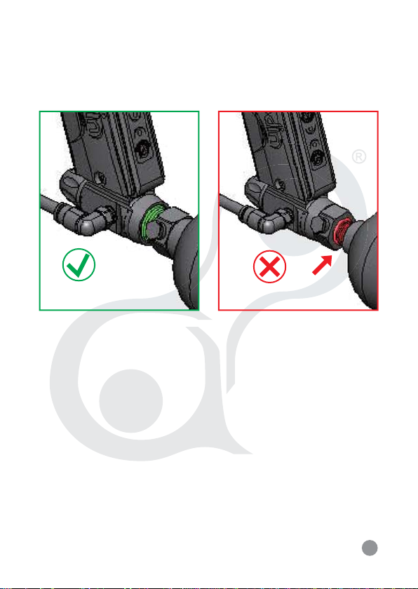
Look at the valve when removing the tank from the marker’s On/Off
Bottom ASA (A091). Make sure that the valve is turning with the
tank instead of staying with the marker.
STOP IMMEDIATELY if valve starts to unscrew from the tank itself.
Screw the tank back onto the marker’s On/Off Bottom ASA adapter
and contact a qualified airsmith for further assistance.
4
Page 8

®
GETTING STARTED
1. First, place the BARREL BLOCKING DEVICE over the barrel.
2. Always point your marker at a “SAFE” direction before use.
To use, press the Top Button once on the back of the grip
frame. Doing this the Upper LED will show Red Light and the
marker will be in Safe Mode. To unlock from the Safe Mode,
point the marker in a Safe Direction, and press the Bottom
Button once. Doing this the Upper LED will show Green Light
and the marker will be ready to play.
* For detailed operation of the electronics please refer to page (7)
3. Firmly screw in the CO2/ HPA/ N2 air tank to the On/Off Bottom
ASA (A091). Tighten the air tank clockwise all the way in the
marker’s On/Off Bottom ASA.
CAUTION: Never use any hand tool to screw air tank to the
bottom ASA.
4. Attach a paintball hopper/ loader to the marker’s feed neck.
5. Remove the barrel blocking device and unlock the safe mode.
CAUTION: Now the marker is LIVE, pulling the trigger will
fire a paintball. Only test your marker at the safe direction
or in a proper organized paintball field.
5
Page 9

®
6. Check marker’s velocity FPS (Feet Per Second). Turning the
Velocity Adjuster (P023) clockwise will increase the velocity.
Counterclockwise will decrease the velocity.
7. After playing, take out all paintballs from the hopper. Then
detach the hopper from the marker.
CAUTION: There may be 1-2 paintballs in the breach area;
take a couple more shots in a safe direction to make sure
the marker is empty of paintballs.
8. Place the barrel blocking device over the barrel and push the
safety button in the safe mode.
9. Unscrew the CO2/ HPA/ N2 air tanks from the marker’s bottom
ASA.
CAUTION: Never use any hand tool to screw air tanks to the
bottom ASA.
10. Store the marker in a paintball bag or in a safe place.
6
Page 10

®
USING THE ZEN BOARD
TO TURN ON THE BOARD: Press the Top Button once to turn on
the board. Upper LED will show Red Light (Safe Mode) and Lower
LED will show Green Light (Default setting is Semi-Auto mode)
or your previous setting (The ZEN Board will memorize last
setting of shooting mode).
If Upper LED Light is flashing Red Light, it means battery power
status is low and the battery needs to be change. Battery power
status can be verified by press Top Button once more to confirm.
SAFE MODE: After turning on the board, press Bottom Button
once to turn off the Safe Mode and Upper LED Light will show
Green Light to indicate the Eyes are on.
Press Bottom Button again to turn on the Safe Mode. Right now the
Upper LED Light will show Red Light to indicate the Safe Mode
is on.
EYES ON/OFF: When Safety is on and Upper LED Light is
showing Green Light (Eyes On). Press the Top Button once and
Upper LED Light will change to Change Light to indicate the eyes
are off. To turn the eyes back On, Press Top Button again and
Upper LED Light will showing Green Light again to indicate the
Eyes are back on. When there is a ball break or Eyes are
malfunction, Upper LED Light will flash Green Light. Now press
Top Button to turn off the Eyes and press Top Button again to turn
the back Eyes on to determine the problem. If the Upper LED light
still flash Green Light, clean out the Eyes.
7
Page 11
®
LED COLORS
UPPER LED
RED = SAFE MODE
GREEN = EYES ON
ORANGE = EYES OFF (11.1 BPS)
FLASH RED = LOW BATTERY POWER STATUS
FLASH GREEN = EYES MALFUNCTION (8 BPS)
LOWER LED
GREEN = SEMI-AUTO (20 BPS)
DARK BLUE = PSP RAMP (13.1 BPS)
PURPLE = MILLENIUM RAMP (12 BPS)
LIGHT BLUE = CFOA SEMI (13.1 BPS)
FLASH GREEN = PROGRAMMING MODE
BUTTONS
TOP BUTTON
PRESS ONCE = POWER ON
PRESS AGAIN = VERIFY BATTERY POWER STATUS
PRESS AGAIN = EYES ON/OFF
PRESS AND HOLD = TURN OFF
BOTTOM BUTTON
PRESS ONCE = SAFE MODE ON/OFF
PRESS AND HOLD = ENTERS PROGRAMMING MODE
IN PROGRAMMING MODE
PRESS ONCE = CYCLE THROUGH SHOOTING MODES
PRESS AND HOLD = CONFIRM SHOOTING MODES
*ZEN Board will memorize last setting of shooting mode
8
Page 12
VELOCITY ADJUSTMENTS
(INCREASE & DECREASE VELOCITY)
COUNTERCLOCKWISE
DECREASE VELOCITY
CLOCKWISE
INCREASE
VELOCITY
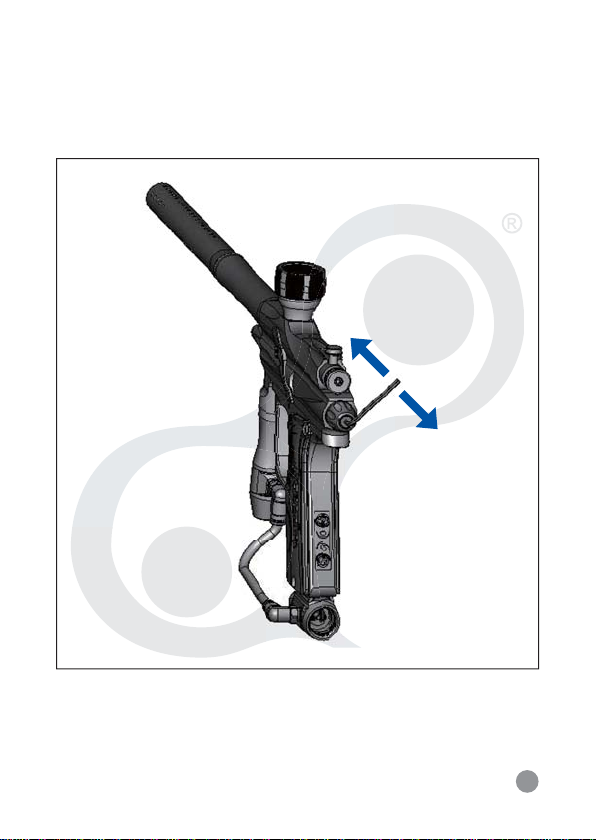
To increase your velocity FPS (Feet Per Second), use the allen
wrench to turn the Velocity Adjuster (P023) clockwise.
To decrease your velocity FPS (Feet Per Second), use the allen
wrench to turn the Velocity Adjuster (P023) counterclockwise.
9
Page 13
REGULATOR ADJUSTMENT
(INCREASE & DECREASE AIR PRESSURE)
CLOCKWISE
INCREASE VELOCITY
COUNTERCLOCKWISE
DECREASE VELOCITY
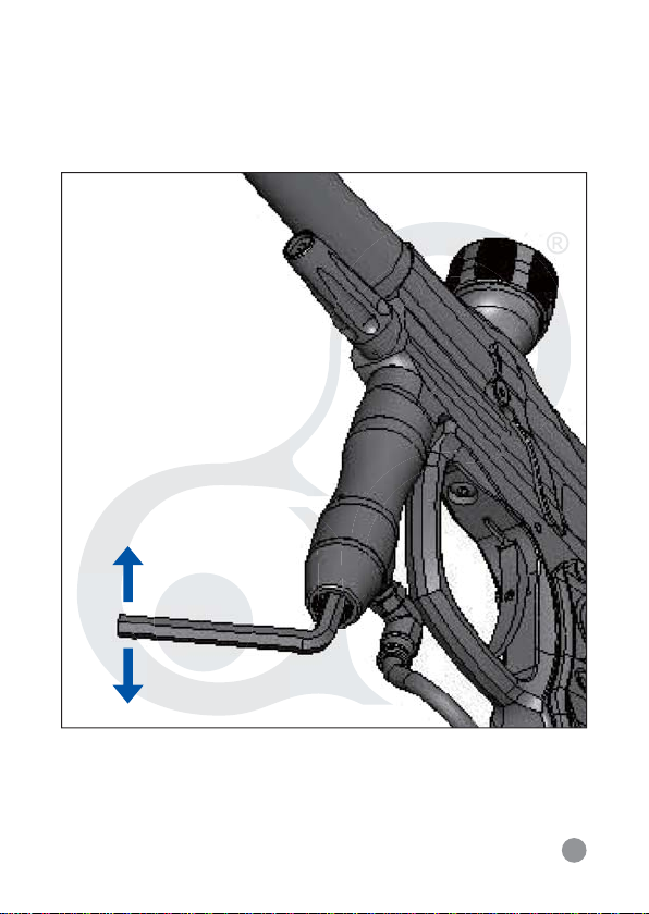
To increase the input pressure use the allen wrench to turn the
Regulator Adjustment Screw (S032) clockwise.
To decrease the input pressure use the allen wrench to turn the
Regulator Adjustment Screw (S032) counterclockwise.
10
Page 14

®
NOTE: Regulator is preset at the factory for optimum performance.
Fine adjustment of velocity should be done with the Velocity
Adjustor (P023) on page 9.
NOTE: Each quarter turn correspond to approximate increase or
decrease of 20psi.
11
Page 15

®
ZeRO SYSTEM
INSTRUCTION AND ADJUSTMENT
WARNING: Never remove the internal of the marker while the
air tank is attached with the marker.
FOR CO2 OPERATION:
NOTE: Zenith is optimized for use with HPA, in order to
optimize the Zenith for CO2 use, please follow the instructions
below.
1. Insert the 3mm allen wrench into the ZeRO Adjustment Screw
(Z001). Turn clockwise two full revolutions.
2. To optimize the velocity, make sure the rear velocity adjustment
is backed all the way out. Adjust the Inline Regulator (refer to
Regulator Adjustment) until the marker is shooting at 250 feet per
second over a chronograph.
3. To fine-tune the marker velocity follow the direction on page 9
(refer to Velocity Adjustment)
FOR HPA OPERATION:
NOTE: Zenith is optimized for HPA use out of the box. Follow
the instructions below only after you have used the CO2
setting and would like to reconfigure for HPA use.
1. Insert the 3mm allen wrench into the ZeRO Adjustment Screw
(Z001). Turn counter-clockwise two full revolutions.
12
Page 16

®
2. To optimize the velocity, make sure the rear velocity adjustment
is backed all the way out. Adjust the Inline Regulator (refer to
Regulator Adjustment) until the marker is shooting at 250 feet per
second over a chronograph.
3. To fine-tune the marker velocity follow the direction on page 9
(refer to Velocity Adjustment)
ADVANCE ADJUSTMENT:
The ZeRO System is a revolutionary combination of the Feather
Striker and a redesign of the Valve Engine. The ZeRO System is
designed to reduce Mechanical Recoil to a minimum by balancing
the output pressure of the Inline Regulator with the timing of the
ZeRO System.
NOTE: The instructions below are for fine-tuning of the ZeRO
System. Do not attempt unless you have a thorough
understanding of the ZeRO System operation.
1. Insert the 3 mm allen wrench into the ZeRO Adjustment Screw
(Z001).
2. Turning Clockwise will tighten the ZeRO Spring to decrease valve
timing. Refer to Step 2 and 3 from above to fine-tune velocity.
NOTE: Decrease valve timing will increase air efficiency but it
will cause an increase in mechanical recoil.
3. Turning Counter-Clockwise will loosen the ZeRO to increase
valve timing. Refer to Step 2 and 3 from above to fine-tune
velocity.
NOTE: Increase valve timing will decrease air efficiency but it
will cause a decrease in mechanical recoil.
13
Page 17
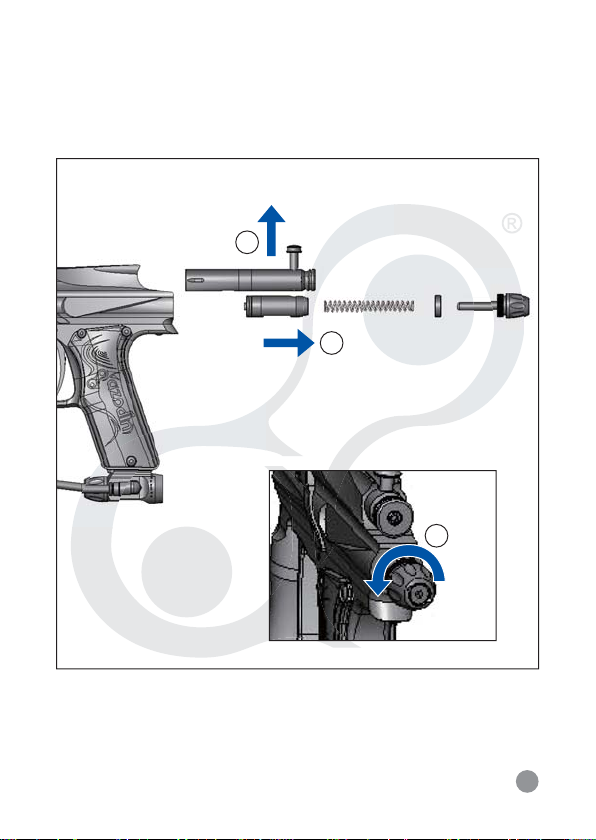
ASSEMBLY AND CLEANING
PULL THE TOP COCKING KNOB
1
2
COUNTERCLOCKWISE THE END CAP
TO LET THE INTERNALS SLIDE OUT
3
WARNING: Never remove the internals of the marker while
the air tank is attached with the marker. Always remove all
paintballs, loader and air tank before disassembling the
marker.
14
Page 18

®
CLEANING AND DISASSEMBLE REAR INTERNALS
1. Lift upward on the Top Cocking Knob at the rear of Delrin Bolt.
This will let the Delrin Bolt (P041) slide out from the rear of the
receiver.
2. Turn the End Cap (A051) counterclockwise. This will let the End
Cap and the marker’s internals to slide out from the rear of the
receiver. Remember to place the marker in the
de-cock position and place light pressure behind the End Cap
during the removal of the End Cap, this way will prevent the
internals to spring out.
3. Slide the Feather Striker (P021) out of the rear of the receiver.
4. Once all the internal parts are removed, use a squeegee to clean
the inside of the receiver and use a towel to clean the dirt or
paint off of Delrin bolt. Apply some paintball gun oil on the Striker
O-Ring regularly.
15
Page 19

®
REASSEMBLE REAR INTERNALS
1. Insert the Feather Striker (P021) thru the rear of the receiver
with the O-Ring facing towards the front of the marker and
with the hole on the Feather Striker facing upright. While
inserting the Feather Striker, apply pressure behind the Feather
Striker and at the same time pull the Trigger to let Feather
Striker enter the rear chamber of the receiver.
2. Insert the Feather Bumper (P024) thru the receiver and insert
the ZeRO Feather Spring (P025) thru the Feather Bumper.
3. Insert the End Cap (A051) with the Velocity Adjuster (P023)
Thru the Feather Bumper and Feather Spring.
4. Turn the End Cap (A051) clockwise to tighten it and hold the
internals in place.
5. Insert the Bolt Assembly (P041) thru the rear of the receiver.
Press downward on the Top Cocking Knob (At the rear of Bolt
Assembly) to connect and enter the hole of Feather Striker to
fasten with the Feather Striker. Use a small tool such as allen
wrench to align the hole of the Feather Striker.
16
Page 20

®
TROUBLESHOOTING
WARNING: Always remove all paintballs, loader and air tank
before disassembling the marker.
RECOCKING ISSUES
Need Lubrication on the Striker O-Ring (R011).
Striker O-Ring is damaged or missing. Replace a correct O-Ring.
The pressure in the tank is too low and needed to be refilled.
Dirt or broken paintball shell fragments in the receiver. Check,
cleaning, and disassemble rear internals.
AIR LEAKS
Air leaking from the low pressure chamber. Check AZ O-Ring
(R015), replace or need to be oiled.
Air leaking from under the barrel is normally caused by worn or
damaged ZeRO Cup Seal (R013). Check the guide for removal of Cup
Seal / Valve Body.
A scratch on the Valve Body will cause air leak.
Air leaking from the receiver and throughout the Grip frame. Check
Valve O-Rings and replace.
17
Page 21
®
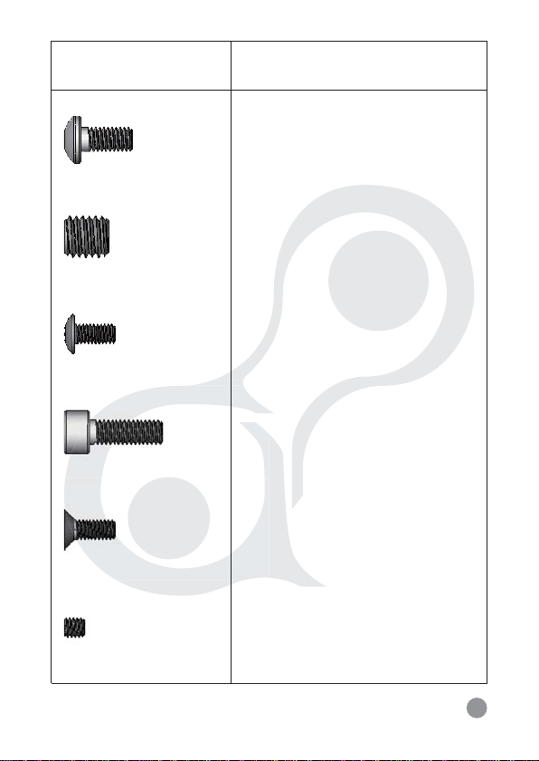
ZENITH SCREW CHART
SIZE: 1:1
PART NUMBER AND NAME
S011 M5 X 10L
MAIN BODY SCREW
S012 M8 X 8L
VALVE RETAINING SCREW
S016 M4 X 8L
GRIP PANEL SCREW
S017 M5 X 14L
VERTICAL ASA SCREW
S018 M4 X 8L
EYE COVER SCREW
S031 M4 X 4
REGULATOR RETAINING
SCREW
18
Page 22
®
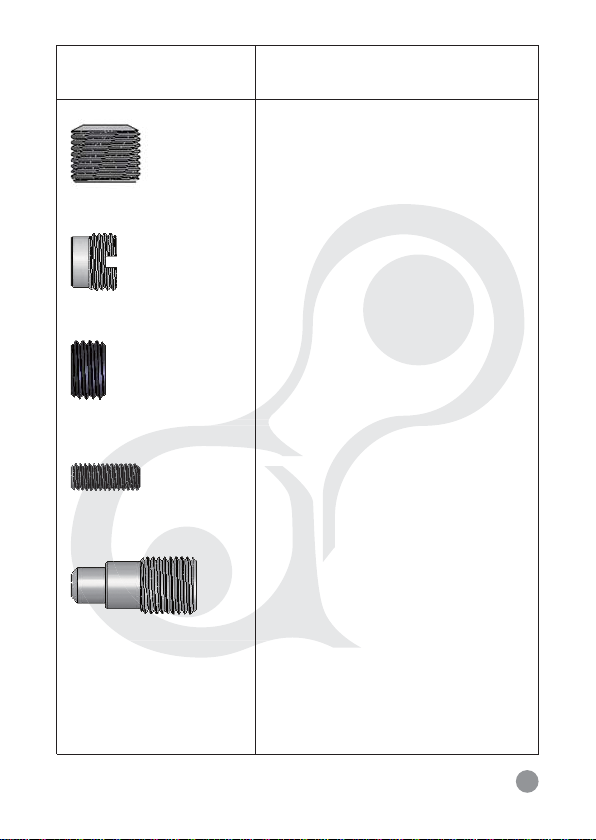
ZENITH SCREW CHART
SIZE: 1:1
PART NUMBER AND NAME
S032 M12 X 8L
REGULATOR ADJUSTMENT
SCREW
S091
ON/OFF BOTTOM ASA
RETAINING SCREW
S092 1/8-27 NPT
ON/OFF BOTTOM ASA
HOSE PLUG
S093 M5 X 12L
ON/OFF BOTTOM ASA SCREW
Z031
ZeRO ADJUSTMENT SCREW
19
Page 23
®
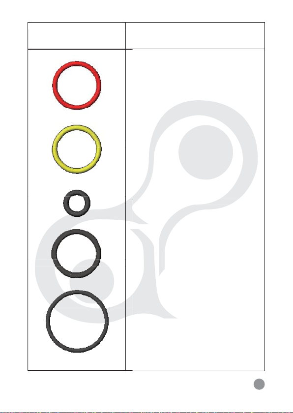
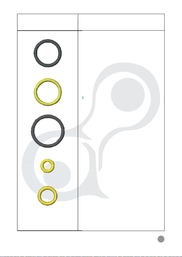
ZENITH O-RING CHART
SIZE: 1:1
PART NUMBER AND NAME
R011
STRIKER O-RING
(RED)
R012
FRONT VALVE O-RING
(CLEAR)
R013
VELOCITY ADJUSTER O-RING
(BLACK)
R015
AZ O-RING
(BLACK)
R016
BARREL O-RING
(BLACK)
20
Page 24
®
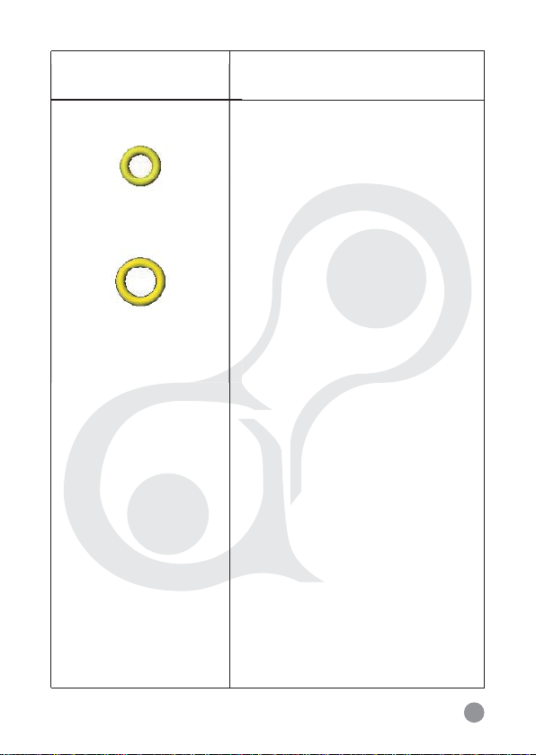
ZENITH O-RING CHART
SIZE: 1:1
PART NUMBER AND NAME
R017
END CAP O-RING
(BLACK)
R031
REGULATOR PISTON O-RING
(CLEAR)
R032
REGULATOR SWIVEL
MOUNT O-RING (BLACK)
R033
REGULATOR INNER O-RING
(CLEAR)
R034
REGULATOR SEAL O-RING
(CLEAR)
21
Page 25
®
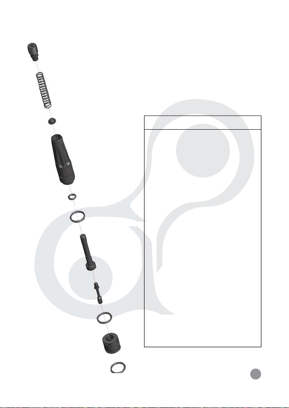
ZENITH O-RING CHART
SIZE: 1:1
PART NUMBER AND NAME
R091
ON/OFF BOTTOM ASA O-RING
(CLEAR)
Z021
ZeRO CUP SEAL O-RING
(CLEAR)
22
Page 26
®
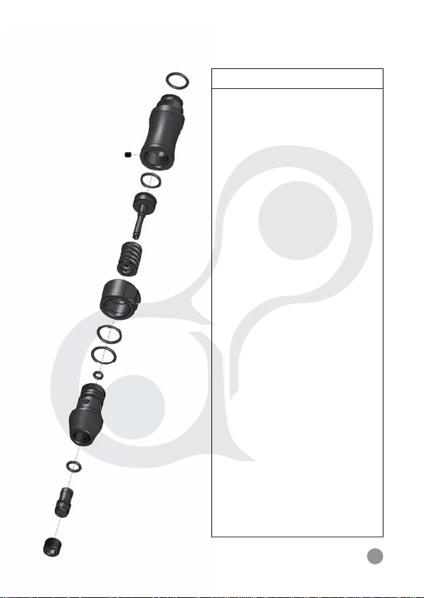
Z001 ZeRO SYSTEM
Z031
Z014
Z041
Z021
R015
Z013
Z012
Z011
R012
P011
R015
ZeRO SYSTEM PARTS LIST
PART NAME
NO
VALVE
P011
Z011
ZeRO CUP SEAL
STEM
Z012
ZeRO CUP SEAL
Z013
ZeRO SPRING GUIDE
Z014
ZeRO SPRING
R012
FRONT VALVE
O-RING (CLEAR)
R015
AZ O-RING
Z021
ZeRO CUP SEAL
O-RING
Z031
ZeRO ADJUSTMENT
SCREW
Z041
ZeRO HOUSING
23
Page 27
®
A062 INLINE REGULATOR
P082
P086
P085
R034
S031
P084
R033
P083
P081
R031
R032
R032
R015
REGULATOR PARTS LIST
NO
PART NAME
P081
MAIN REGULATOR
HOUSING
P082
REGULATOR SWIVEL
MOUNT
P083
REGULATOR
END CAP
REGULATOR PISTON
P084
REGULATOR MAIN
P085
SPRING
SEAT SEAL CARRIER
P086
AZ O-RING
R015
REGULATOR PISTON
R031
O-RING
REGULATOR SWIVEL
R032
MOUNT O-RING
REGULATOR INNER
R033
O-RING
REGULATOR SEAL
R034
O-RING
REGULATOR
S031
RETAINING SCREW
REGULATOR
S032
ADJUSTMENT SCREW
S032
24
Page 28
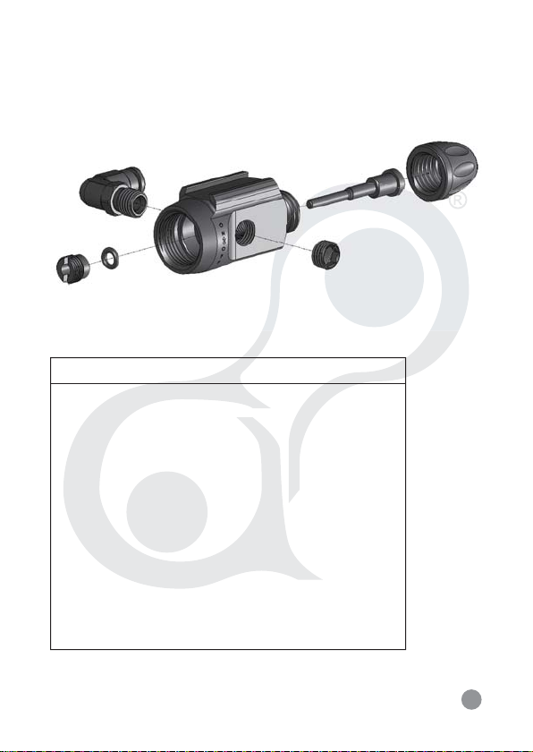
A091 ON/OFF BOTTOM ASA
P063
R091
A093
S091
ON/OFF BOTTOM ASA PARTS LIST
PART NAME
NO
P063
90 DEGREE MACROLINE HOSE
P091
ON/OFF BOTTOM ASA STEM
ON/OFF BOTTOM ASA O-RING
R091
ON/OFF BOTTOM ASA RETAINING SCREW
S091
ON/OFF BOTTOM ASA HOSE PLUG
S092
P091
A092
S092
ON/OFF BOTTOM ASA CAP
A092
A093
ON/OFF BOTTOM ASA MAIN BODY
25
Page 29

®
ZENITH PARTS LIST
NO
PART NAME
NO
PART NAME
P011
VALVE
P021
FEATHER STRIKER
P023
VELOCITY ADJUSTER
P024
FEATHER BUMPER
P025
ZERO FEATHER
SPRING
BALL DETENT
P031
EYE COVERS
P033
BOLT ASSEMBLY
P042
TWIST LOCK
P051
FEEDNECK
90 DEGREE
P063
MACROLINE ELBOW
ZENITH MACROLINE
P073
HOSE
STRIKER O-RING
R011
(RED)
VELOCITY
R013
ADJUSTER O-RING
AZ O-RING
R015
BARREL O-RING
R016
END CAP O-RING
R017
S011
MAIN BODY SCREW
S012
VALVE RETAINING
SCREW
S016
GRIP PANEL SCREW
S017
VERTICAL ASA
SCREW
EYE COVER SCREW
S018
ON/OFF BOTTOM ASA
S093
SCREW
ZENITH BODY
A013
VERTICAL ASA
A032
END CAP
A051
INLINE REGULATOR
A062
E-GRIP FRAME
A072
ASSEMBLY
GRIP PANEL
A082
A091
ON/OFF BOTTOM ASA
A211
5” .689 BARREL BACK
A221
9” BARREL FRONT
Z001
ZeRO SYSTEM
26
Page 30
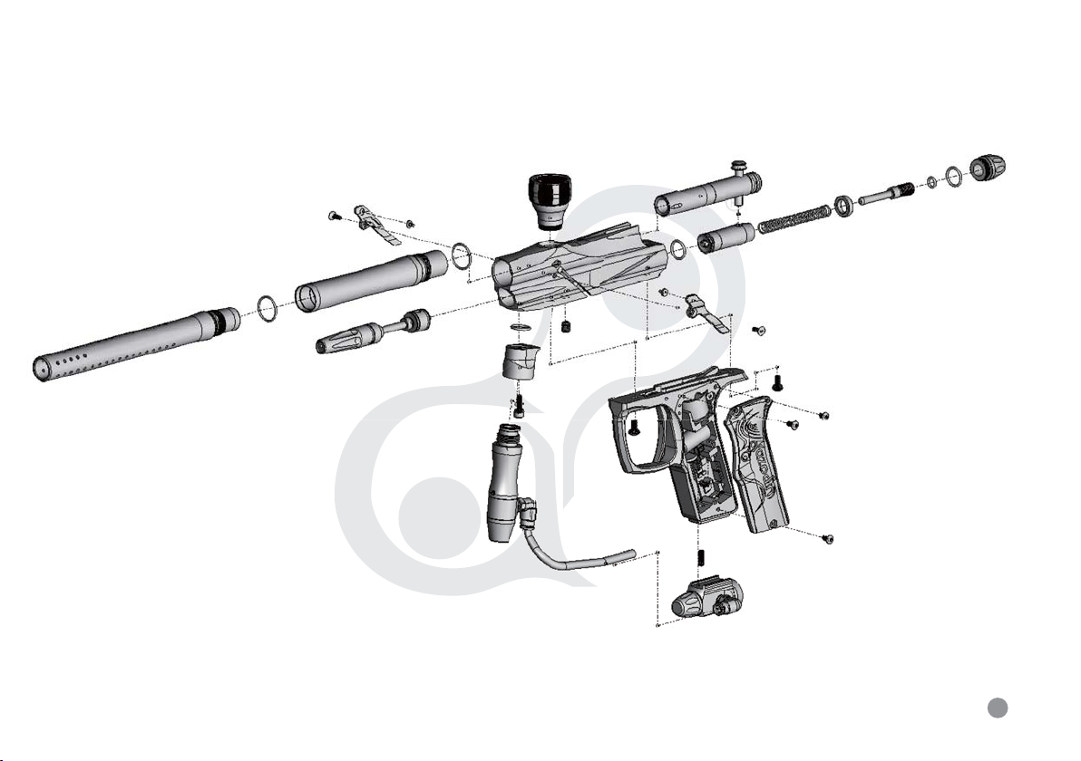
ZENITH EXPLODED VIEW
A221
P033
S018
A211
R016
P011
Z001
PLEASE REFER TO PAGE 23
FOR DETAIL OF ZeRO SYSTEM
PLEASE REFER TO PAGE 24
FOR DETAIL OF INLINE
REGULATOR
P031
A062
R016
R015
A032
P051
S017
P063
S012
P073
A013
S011
A072
R011
P031
P041
P024
P023
P025
P021
P033
S018
S011
S016
S016
A082
S016
S093
PLEASE REFER TO PAGE 25
A091
FOR DETAIL OF ON/OFF BOTTOM ASA
A051
R013
R017
27
Page 31

®
www.azodin.com
beyond limitation
 Loading...