

Page 1
!WARNING!
IMPORTANT SAFETY INSTRUCTION AND GUIDELINS
!WARNING!
IMPORTANT CO2/ HPA AIR TANK SAFETY INSTRUCTION AND GUIDELINES
GETTING STARTED
This Paintball Marker is NOT A TOY. Misuse can cause serious
•
injury or death.
• Recommend 18 years or older to purchase this product. Person
under 18 must have adult supervision.
• Read this manual, understand and follow the manual
instructions for using this product.
• Eye and face protection specially designed for paintball use,
must be worn by user and persons within range at all times.
• Treat all paintball markers as if it were loaded and able to re.
• Never look down the barrel or breech area of a marker.
• Always use barrel blocking device when the marker is not in use.
• Always chronograph this marker before playing paintball.
• Never shoot any marker at velocities exceeds 300 FPS (Feet
Per Second), or velocities which is greater than local elds or
national laws allow.
• Ensure all air lines and ttings are tightened and secured before
installing the air tanks.
• Do not shoot at people, animals, houses, cars or anything is not
related to the sport of paintball.
• Always keep the marker in Safe mode until ready for use.
• Fire only 0.68 caliber paintballs with this marker.
• Always make sure the bolt is in the un-cocked position when
marker is not in use.
• Any modications or tampering of original factory parts will
cause all warranties and liabilities from Azodin.
• Tank valves must be installed or removed by qualied personnel.
• All tanks must be retested before the expiration date.
• Improper use, lling, storage of this air tank may cause death,
serious injury and property damage.
• Air tanks must be lled only by properly trained personnel.
• Do not over pressurize. Do not expose pressurized tanks to
temperatures in excess of 130F° degrees (54°C).
• Do not expose tanks to corrosive materials and do not clean with
caustic cleaners.
• Do not alter tanks in any way.
• Tanks heated up to a temperature of 250F° degrees (54°C) or
more must be condemned or re-qualied.
• Keep air tanks out of reach of children.
• The valve should NEVER detach from the tank canister. Should
this occur, seek assistance from a qualied airsmith immediately.
• Air tanks are use for the sport of paintball only.
1. First, place the BARREL BLOCKING DEVICE over the barrel.
2. Always point your marker in a “SAFE” direction when not in play.
The Safety is ON when it protrudes out on the right hand side of the
grip frame. Point the marker in the safe direction before unlocking
it.
To disengage the Safety, push the Safety Button so it protrudes
out on the left side of the grip frame.
3. Firmly screw in the CO2/ HPA/ N2 air tank to the bottom ASA
(KBA2). Tighten the air tank clockwise all the way into the
marker’s bottom ASA until it stops.
CAUTION: Never use any hand tools to screw the air tank
into the bottom ASA.
4. Attach a paintball hopper/ loader into the marker’s feedneck.
5. Pump the handle back and pull it forward to it’s starting position.
6. Remove the barrel blocking device and disengage the safe mode.
CAUTION: Now the marker is LIVE, pulling the trigger will
re a paintball. Only test your marker in a safe direction
or on the paintball eld.
7. Push the trigger’s safety switch from right to left.
The marker’s is now ready to re.
8. Check marker’s velocity FPS (Feet Per Second). Turning the
velocity adjuster (VA01) clockwise will increase the velocity.
Counterclockwise will decrease the velocity.
GETTING THE MARKER
READY FOR STORAGE
• This owner’s manual should always accompany this marker
for reference and in the event of resale and new ownership.
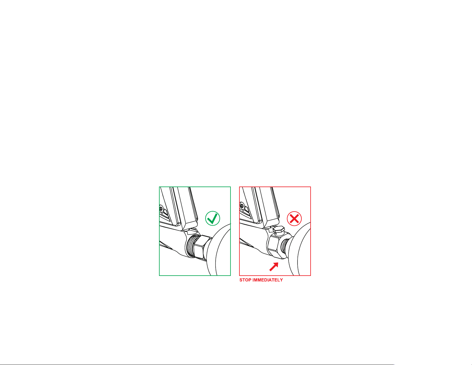
CO2 or HPA/ N2 Air tanks will have enough force to y off and cause
serious injury or death if the valve unscrews from the tank head.
Look at the valve when removing the tank from the marker's
Bottom ASA (KBA2). Make sure that the valve is turning with the tank
instead of staying with the marker.
STOP IMMEDIATELY if valve starts to unscrew from the tank itself.
Screw the tank back onto the marker's Bottom ASA adapter and contact
a qualied airsmith for further assistance.
1. Push the tirgger’s safety switch from left to right.
This will engage the safety and not allow the trigger to re
the marker.
2. After playing, empty out all the paintballs from the hopper.
Then detach the hopper from the marker.
CAUTION: There may be 1-2 paintballs in the breach area;
To remove the paintballs you can turn the marker upside down
or re it into a safe area.
3. Unscrew the barrel from the marker.
4. You may now store the marker.
Page 2
VELOCITY ADJUSTMENTS
ASSEMBLY AND CLEANING
THE MARKER
PULL PUMP BOLT PIN (PBP3)
WARNING: Do not turn the velocity adjust clockwie more
than 6 turns. This may strip the threads on
the Velocity Adjuster and End Cap.
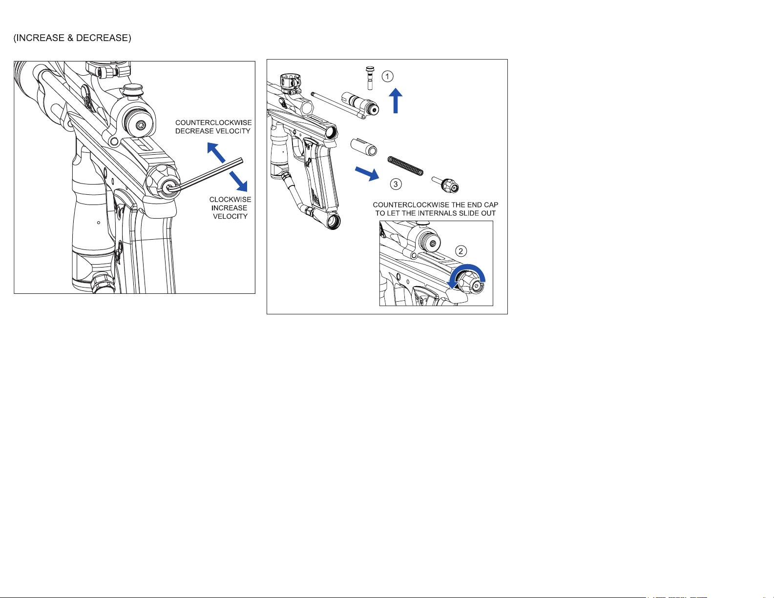
To increase your velocity FPS (Feet Per Second), use
the allen wrench to turn the Velocity Adjuster (VA01)
clockwise.
To decrease your velocity FPS (Feet Per Second), use
the allen wrench to turn the Velocity Adjuster (VA01)
counterclockwise.
WARNING: Never remove the internals of the marker
while the tank is attached to the marker. Always remove
the loader, the air tank, and all paintballs from the marker
before disassembly.
Page 3

HOW TO CLEANING AND DISASSEMBLE REAR
INTERNALS
1. Pull the Top Cocking Knob (PBP3) up.
2. Pull the Bolt (PB03) out the back of the Pump Slide
(PA02).
3. Turn the End Cap (EC02) counterclockwise until it is
free of the marker’s body.
4. Remove the Pump Striker Spring (PSS2) from the
Marker.
5. Tilt the marker backwards and slide the Pump Striker
(PS02) out of the marker.
It may get caught on the trigger sear. If this happens,
pull the striker out using a nger.
You may also push the striker out from the top of the
marker with an allen key.
6. Use a squeegee or barrel swab to clean the inside of
the body.
Use a towel or rag to remove any paint or debris from
the Pump Bolt (PB03).
7. Turn the End Cap (EC02) clockwise until it is ush
with the body.
CLEANING AND DISASSEMBLE KPC KIT
1. Unscrew the Retatining Screw (4M x 4L) on the
KP Handle (KH01).
This will let the KP Handle slide out from the
KP PUMP CAP (PC01).
2. Remove the KP Handle, use a towel to clean the dirt
or paint of KP Stablizing Rod. Apply 1-2 drops of
paintball gun oil at both of the AZ O-Ring (R010).
REASSEMBLE KPC KIT
1. Install the KP Handle onto KP Stablizing Rod and
KP Am.
2.Screw the KP Screw back into the KP Handle to
fasten it.
TROUBLESHOOTING
WARINIG: Remove all paintballs, loaders, and air tanks
before disassembling the marker.
Symptoms
Leaks down the barrel /
body and trigger frame
Leaks between Body and
Vertical Adapter
Leaks from middle of the
regulator, small hole above
the set screw
Leaks from ASA, small hold
on the bottom
(nearest the tank)
Repair Step(s)
1. Tighten M8 x 8L Screw
2. Replace Cup Seal (CS01)
3. Replace Orings RP15 and R015
4. Replace Valve (MFV2)
1. Replace R015 Oring between
Vertical Adapter (KVAS1) and
Body (KCB)
1. Replace RV09 Oring
2. Replace RV14 Oring
1. Replace the Tank’s Oring
7. Apply a thin layer of Azodin lube to the Bolt Orings
(RO15) and the Pump Striker (PS02).
HOW TO REASSEMBLE THE REAR INTERNALS
1. Insert the Pump Striker (PS02) into the lower tube of
the marker.
Make sure the U-shapde cut is facing upwards,
towards the bolt.
The striker will get stuck on the trigger sear.
In order to clear the sear, you will need to push and
hold the striker forward.
Then pull the trigger to disengage the sear.
2. The striker should now be clear of the sear. If it is
caught again, repeat the actions described in step
one.
3. Insert Pump Bolt (PB03) into the Pump Slide (PA02).
4. Insert Pump Bolt Pin (PBP3) into the hole, located
above the Pump Slide (PA02).
5. Insert the Pump Spring (PSS2) into the lower tube.
6. Insert the End Cap (EC02) into the back of the marker.
Check to see that the Velocity Adjuster (VA01) goes
through the Pump Striker Spring (PSS2).
TROUBLESHOOTING
WARINIG: Remove all paintballs, loaders, and air tanks
before disassembling the marker.
Symptoms
Leaks from Pump Guide
(PC01)
Loose ASA 1. Tighten M5 x 10L screw
Striker is not catching the
sear when pump handle is
pulled back
If you have questions or require further assistance, please
contact Azodin Paintball.
Email: [email protected]
Phone: 626-330-7262
Repair Step(s)
1. Replace R015 Oring
located inside of the trigger
frame
1. Striker may not be in the right
orientation. Rotate the striker
180 degrees.
2. Check to make sure the
Bolt Pin (PBP3) is pushed all
the way down
Page 4
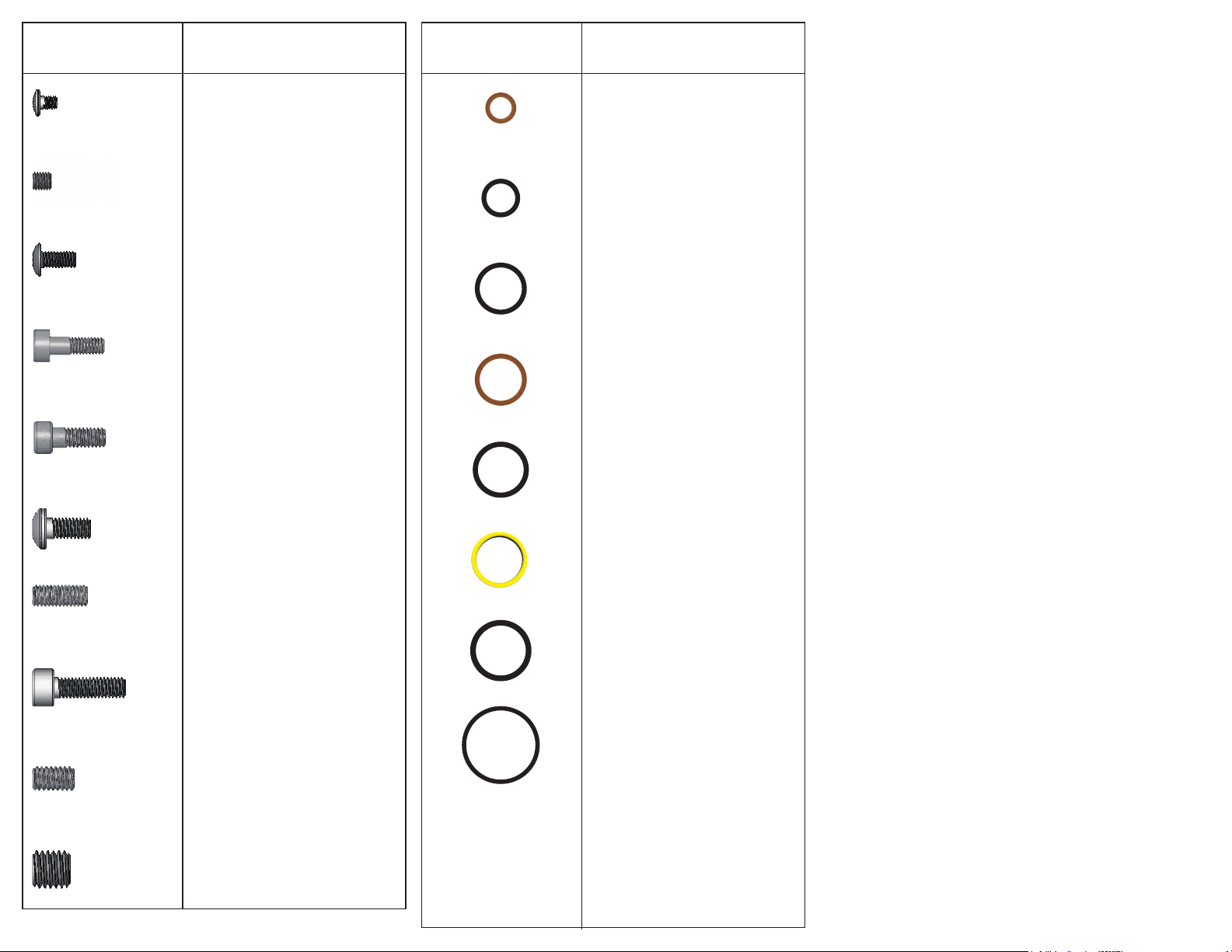
KPC SCREW CHART
SIZE: 1:1
PART NUMBER AND NAME
KPC O-RING CHART
SIZE: 1:1
PART NUMBER AND NAME
M3 x 3.5L
DETENT COVER SCREW
M4 x 4L
RETAINING SCREW
M4 x 8L
GRIP PANEL SCREW
M4 x 9.5L
FEEDNECK LOCK SCREW
M4 x 12L
FEEDNECK LOCK SCREW
M5 x 10L
MAIN BODY SCREW
M5 x 12L
BOTTOM ASA RETAINING
SCREW
M5 x 16L
VERTICAL ASA SCREW
RV09
NO.9 O-RING
(BROWN)
R010
NO.10 O-RING
(BLACK)
R014
NO.14 O-RING
(BLACK)
RV14
NO.14 O-RING
(BROWN)
R015
AZ O-RING
(BLACK)
RP15
FRONT VAVLE O-RING
(CLEAR)
R016
NO.16 O-RING
(BLACK)
M6 x 8L
BOLT SCREW
M8 x 8L
VALVE SCREW
RB01
BARREL O-RING
(BLACK)
Page 5
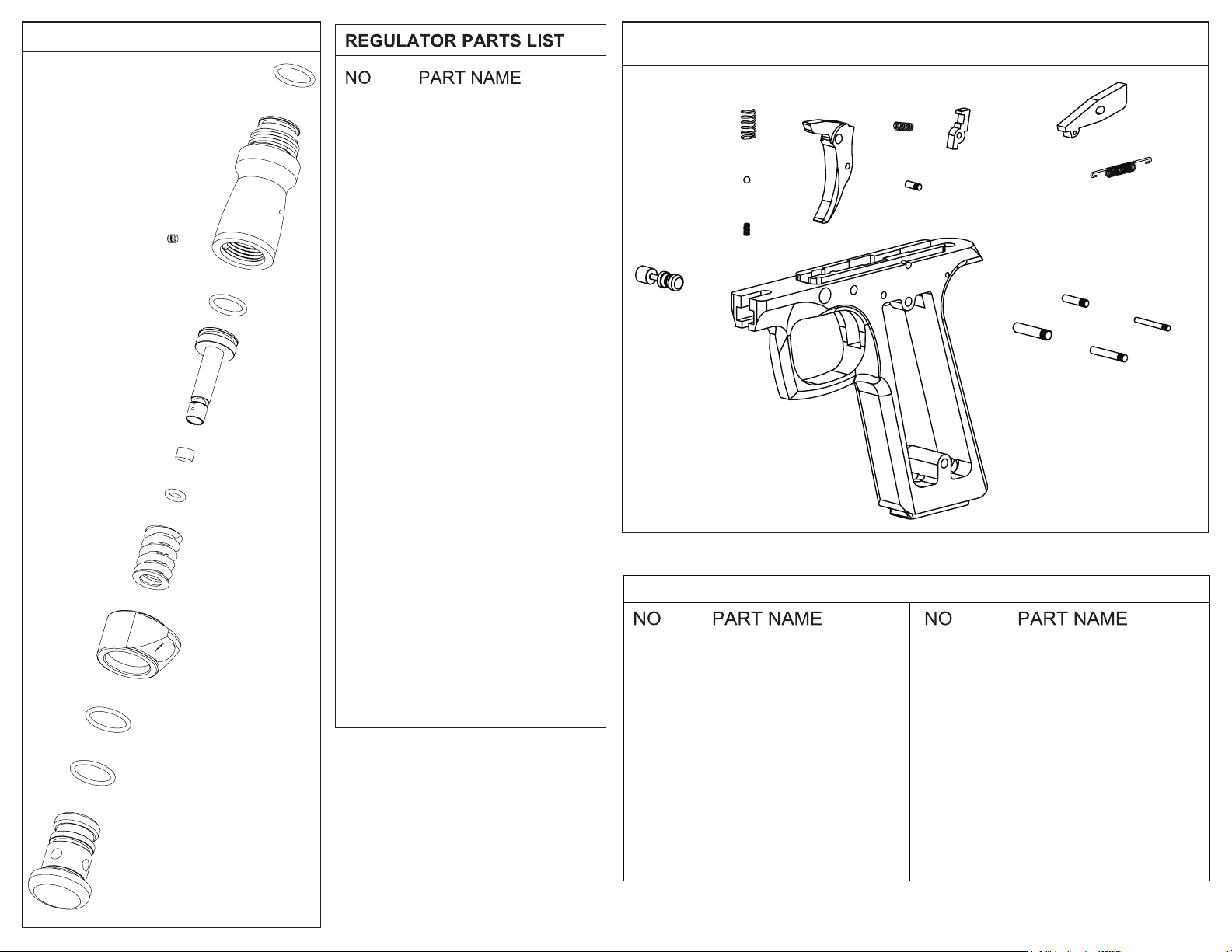
KPC PRESET REGULATOR ON/OFF BOTTOM ASA EXPLODED VIEW
R015
M4 x 4L
PST1
RV09
RMS2
RH03
RV14
RP02
M4 x 4L
PST1
REC3
RH03
RMS2
RP02
RV09
RV14
R015
R016
SM02
RETAINING SCREW
REGULATOR PISTON
REGULATOR
END CAP
MAIN REGULATOR
HOUSE
REGULATOR MAIN
SPRING
REGULATOR PISTON
NO.9 O-RING
(BROWN)
NO.14 O-RING
(BROWN)
NO.15 O-RING
(BLACK)
NO.16 O-RING
(BLACK)
REGULATOR SWIVEL
45 MOUNT
STR1
TSP1
SPB1
SPS1
SP01
ST02
KPC SINGLE TRIGGER FRAME
TSS1
TS01
2.5 x 7.2L
4 x 19.8L
SR01
SSP1
3 x 13.5L
2 x 17.6L
3 x 17.6L
SM02
R016
R016
REC3
SP01
SPS1
SPB1
SR01
SSP1
ST02
STR1
TS01
SAFETY PIN
SAFETY PIN SPRING
SAFETY PIN BALL
SEAR
SEAR SPRING
SINGLE TRIGGER
FRAM
TRIGGER
TRIGGER SEAR
TSP1
TSS1
2 x 17.6L
2.5 x 7.2L
3 x 13.5L
3 x 17.6L
4 x 19.8L
TRIGGER SPRING
TRIGGER SEAR
SPRING
SEAR SPRING PIN
TRIGGER SEAR PIN
SEAR PIN
SEAR PIN
TRIGGER PIN
Page 6
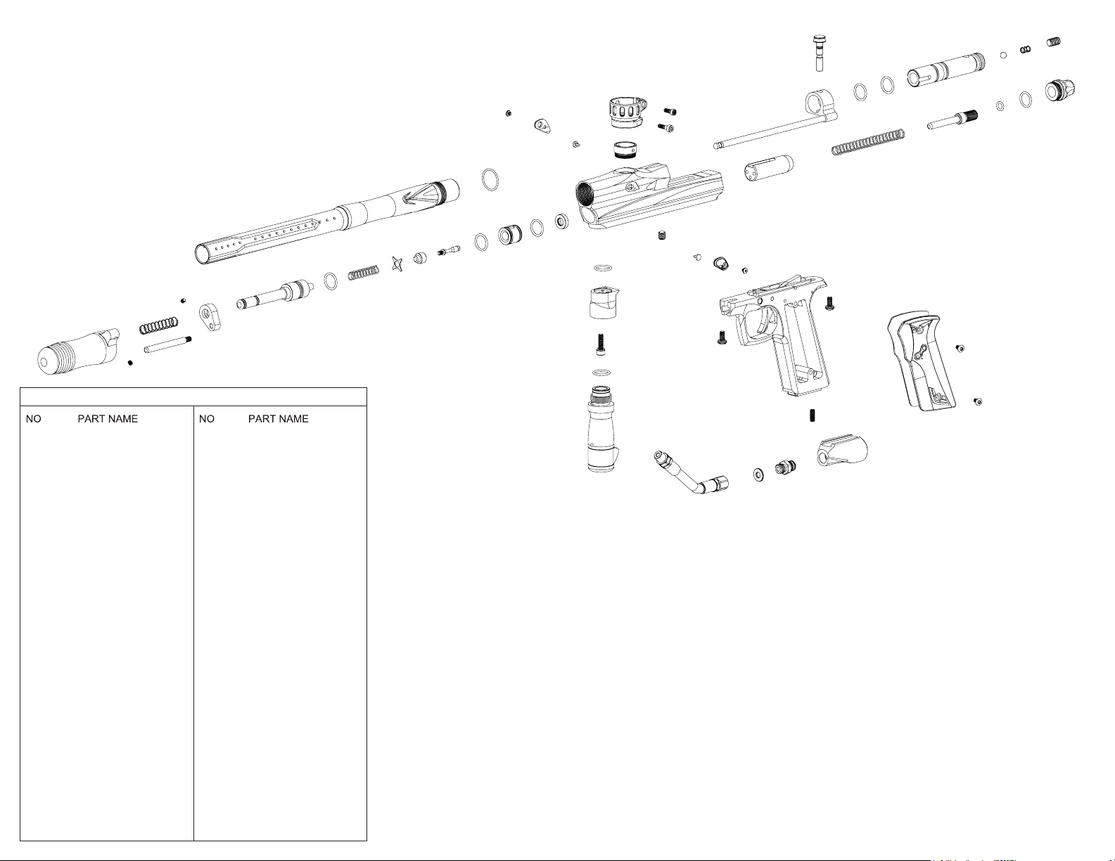
KPC EXPLODED VIEW
M4 x 4L
KRS1
KH01
KR01
M4 x 4L
KPC PARTS LIST
BB01
BD01
BH78
BHE1
BSP1
CS01
CSG1
DC01
EC02
FE01
KBA2
KCB
KCBR
KH01
KR01
KRS1
KSZ1
KSZR
KVAS1
M3 x 3.5L
M4 x 4L
M4 x 8L
M4 x 9.5L
M4 x 12L
M5 x 10L
BOLT SCREW
BALL DETENT
78L BRAIDED HOSE
BRAIDED HOSE
ELBOW
BOLT SPRING
CUP SEAL
CUP SEAL GUIDE
DETENT COVER
END CAP 2
FEEDNECK ELBOW
BOTTOM ASA
KPC BODY
KPC 14” BARREL
KPC HANDLE
KPC GUIDING ROD
KPC RETURN SPRING
KPC STABILIZER
KPC STABILIZER ROD
VERTICAL ASA
DETENT COVER
SCREW
RETAINING SCREW
GRIP PANEL SCREW
FEEDNECK LOCK
SCREW
FEEDNECK LOCK
SCREW
MAIN BODY SCREW
KSZ1
M5 x 12L
M5 x 16L
M6 x 8L
M8 x 8L
MFV2
PA02
PB03
PBP3
PC01
PCSS2
PS02
PSS2
PSR1
R010
R014
R015
RB01
RP15
SLF1
ST02
STP1
SW01
VB01
VS01
KCBR
R015
PC01
VERTICAL ASA SCREW
VERTICAL ASA SCREW
BLOT SCREW
VALVE SCREW
MASS FLOW VALVE
KPC PUMP SLIDE
PUMP BOLT
PUMP BOLT PIN
PUMP CAP
PUMP CAP SEAL STEM
PUMP STRIKER
PUMP STRIKER
SPRING
KPC PRESET
REGULATOR
NO.10 O-RING (BLACK)
NO.14 O-RING (BLACK)
NO.15 O-RING (BLACK)
BARREL O-RING
NO.15 O-RING (CLEAR)
SCREW LOCK
FEEDNECK
SINGLE TRIGGER
FRAME
SINGLE TRIGGER
PANEL
SEAL WASHER
VALVE BUMPER
VALVE SPRING
VS01
CSG1
PCSS2
CS01
M3 x 3.5L
RP15
DC01
RB01
MFV2
BD01
VB01
R015
KVAS1
M5 x 16L
R015
R015
RH03
FE01
SLF1
M8 x 8L
M4 x 9.5L
M4 x 12L
KCB
BD01
DC01
M5 x 10L
BH78
PA02
KSZR
PS02
M3 x 3.5L
ST02
BHE1
SW01
PBP3
R015
M5 x 10L
M5 x 12L
R015
PSS2
STP1
KBA2
PB03
VA01
BB01
R010
M4 x 8L
M4 x 8L
BSP1
R014
M6 x 8L
EC02
 Loading...