

AZMIC AZ100LVEL16VTNAR1, AZ100LVEL16VTNA, AZ100LVEL16VTLR2, AZ100LVEL16VTLR1, AZ100LVEL16VTL Datasheet
...
AZ100LVEL16VT
ECL/PECL Oscillator Gain Stage & Buffer with Selectable Enable
1630 S. STAPLEY DR., SUITE 125 • MESA, ARIZONA 85204 • USA • (480) 962-5881 • FAX (480) 890-2541
www.azmicrotek.com
ARIZONA MICROTEK, INC.
FEATURES
• High Bandwidth for ≥1GHz
• Similar Operation as AZ100LVEL16VR
Except in Disabled Condition: Q
HG
is High
• Operating Range of 3.0V to 5.5V
• Minimizes External Components
• Selectable Enable Polarity and Threshold
(CMOS/TTL or PECL)
• Available in a 3x3 mm or 2x2 mm MLP
Package
DESCRIPTION
The AZ100LVEL16VT is a specialized oscillator gain stage with high gain output buffer including an enable.
The Q
HG
/Q¯HG outputs have a voltage gain several times greater than the Q/Q¯ outputs.
MLP 16, 3x3 mm Package (VTL) or DIE (VTX)
The AZ100LVEL16VTL and AZ100LVEL16VTX provide a selectable enable input (EN) that allows
continuous oscillator operation. See truth table for the Enable function. If Enable pull-up is desired in the
CMOS/TTL mode, an external ≤20 kΩ resistor connecting EN to V
CC
will override the on-chip pull-down resistor.
When disabled, the Q
HG
output is forced high and the Q¯HG output is forced low. The AZ100LVEL16VTL/VTX also
provides a V
BB
and 470 Ω internal bias resistors from D to VBB and D¯ to VBB. The VBB pin can support 1.5 mA
sink/source current. Bypassing V
BB
to ground with a 0.01 µF capacitor is recommended.
The outputs Q and Q¯ each have a selectable on-chip pull-down current source. See truth table below for current
source functions. External resistors may also be used to increase pull-down current to a maximum total of 25 mA.
Outputs Q
HG
and Q¯HG each have an optional on-chip pull-down current source of 10 mA. When pad/pin V
EEP
is
left open (NC), the output current sources are disabled and the Q
HG
/Q¯
HG
operate as standard PECL/ECL. When V
EEP
is connected to V
EE
, the current sources are activated. The Q
HG
/Q¯HG pull-down current can be decreased, by using a
resistor to connect V
EEP
to VEE. (See graph on page 5.)
MLP 8, 2x2 mm Package, VTNA, VTNB & VTNC Versions
All MLP 8, 2x2mm versions of the AZ100LVEL16VT provide an enable input that allows continuous oscillator
operation. VTNA and VTNB utilize an enable (EN¯¯ ) that operates in the PECL/ECL mode. When the EN¯¯ input is
LOW, the Q¯ and Q
HG
/Q¯HG outputs follow the data inputs. When EN¯¯ is HIGH, the QHG output is forced high and the
Q¯
HG
output is forced low. VTNC utilizes an enable (EN) that operates in the CMOS/TTL mode. When the EN input
is HIGH, the Q¯ and Q
HG
/Q¯HG outputs follow the data inputs. When EN is LOW, the QHG output is forced high and
the Q¯
HG
output is forced low.
For VTNA, both D and D¯ inputs are brought out and tied to the V
BB
pin through 470 Ω internal bias resistors. In
VTNB and VTNC, the D¯ input is internally tied directly to the V
BB
pin and the D input is tied to the VBB pin through
a 470 Ω internal bias resistor. Bypassing V
BB
to ground with a 0.01 µF capacitor is recommended.
All MLP 8, 2x2mm versions (VTNA, VTNB & VTNC) have the Q, Q
HG
, and Q¯HG current sources disabled,
while the Q¯ output operates with a 4 mA current source to V
EE
.
NOTE: Specifications in the ECL/PECL tables are valid when thermal equilibrium is established.
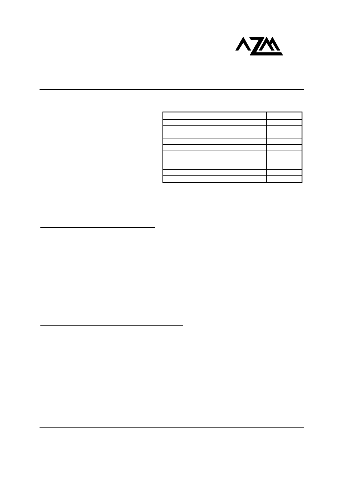
PACKAGE AVAILABILITY
PACKAGE PART NO. MARKING
MLP 8 AZ100LVEL16VTNA TNA
MLP 8 T&R AZ100LVEL16VTNAR1 TNA
MLP 8 AZ100LVEL16VTNB TNB
MLP 8 T&R AZ100LVEL16VTNBR1 TNB
MLP 8 AZ100LVEL16VTNC TNC
MLP 8 T&R AZ100LVEL16VTNCR1 TNC
MLP 16 AZ100LVEL16VTL AZM16T
MLP 16 T&R AZ100LVEL16VTLR1 AZM16T
MLP 16 T&R AZ100LVEL16VTLR2 AZM16T
DIE AZ100LVEL16VTX N/A
AZ100LVEL16VT
November 2003 * REV - 3 www.azmicrotek.com
2
Absolute Maximum Ratings are those values beyond which device life may be impaired.
Symbol Characteristic Rating Unit
VCC PECL Power Supply (VEE = 0V) 0 to +8.0 Vdc
VI PECL Input Voltage (V
EE
= 0V) 0 to +6.0 Vdc
VEE ECL Power Supply (VCC = 0V) -8.0 to 0 Vdc
VI ECL Input Voltage (VCC = 0V) -6.0 to 0 Vdc
I
OUT
Output Current
QHG/Q¯
HG
--- Continuous
--- Surge
Output Current
Q/Q¯ --- Continuous
--- Surge
50
100
25
50
mA
TA Operating Temperature Range -40 to +85
°C
T
STG
Storage Temperature Range -65 to +150
°C
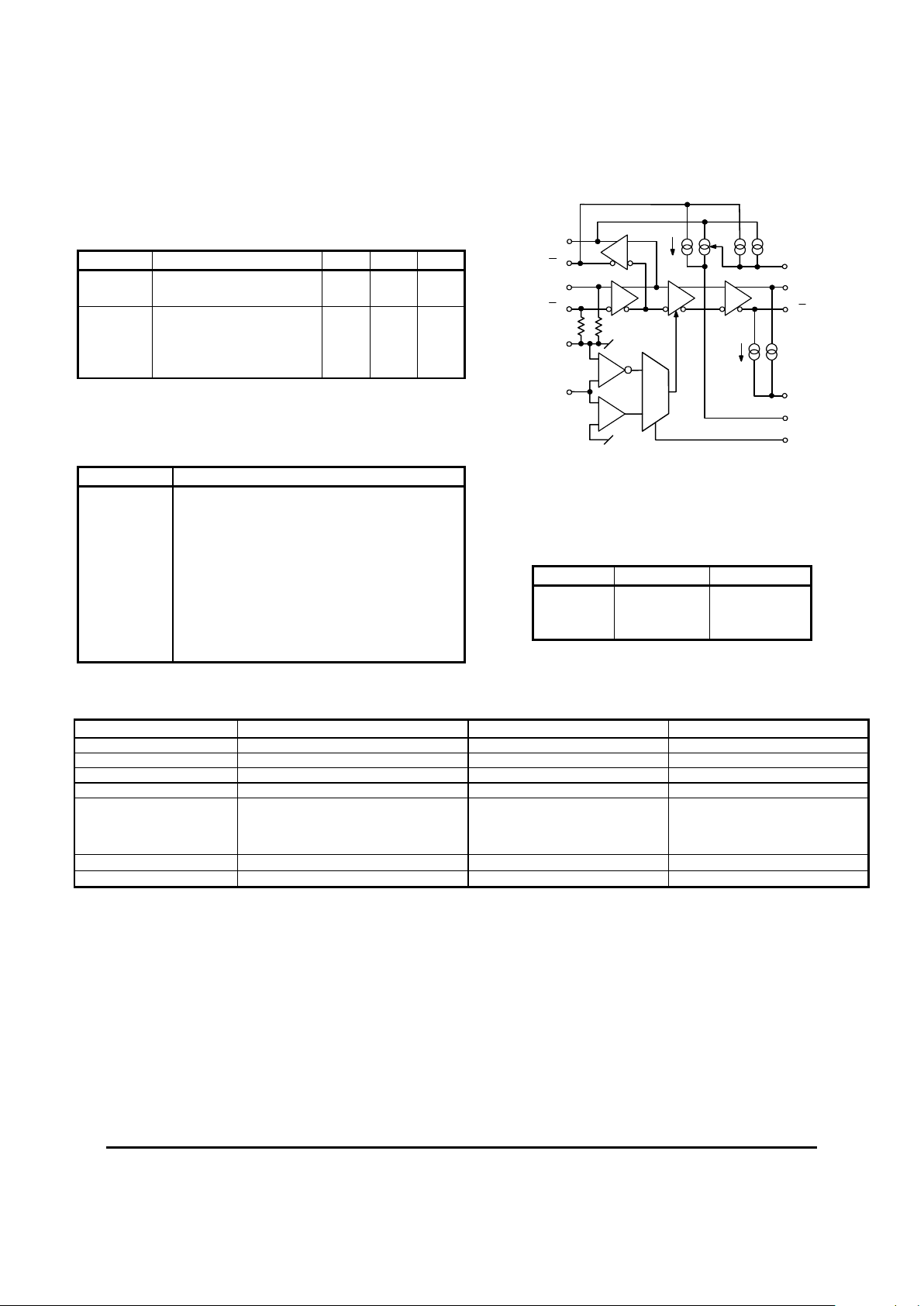
ENABLE TRUTH TABLE
MLP 16 (VTNL) or DIE (VTNX)
EN-SEL EN Q/Q¯ QHG Q¯HG
NC
NC
PECL Low, VEE or NC
PECL High or V
CC
Data
Data
Data
High
Data
Low
VEE*
V
EE
*
V
EE
*
V
EE
*
CMOS Low or V
EE
CMOS High or V
CC
NC, no external pull-up
NC, with ≤20kΩ to V
CC
Data
Data
Data
Data
High
Data
High
Data
Low
Data
Low
Data
*Connections to VCC or VEE must be less than 1Ω.
CURRENT SOURCE TRUTH TABLE
MLP 16 (VTNL) or DIE (VTNX)
CS-SEL Q Q¯
NC
V
EE
*
V
CC
*
4mA typ.
8mA typ.
0
4mA typ.
8mA typ.
4mA typ.
*Connections to VCC or VEE must be less than 1Ω.
PIN DESCRIPTION
PIN FUNCTION
D/D¯ Data Inputs
Q/Q¯ Data Outputs
QHG/Q¯HG Data Outputs w/High Gain
VBB Reference Voltage Output
EN-SEL Selects Enable Logic
EN/EN¯¯ Enable Input
CS-SEL Selects Q and Q¯ Current Source Magnitude
V
EEP
Optional QHG and Q¯HG Current Sources
VEE Negative Supply
V
CC
Positive Supply
Q
D
4mA EA.
470
Ω
V
BB
EN
V
EE
EN-SEL
V
EEP
CMOS / TTL
THRESHOLD
10mA EA.
CS-SEL
Q
HG
Q
D
Q
HG
MLP 16 (VTNL) or DIE (VTNX)
470
Ω
AZ100LVEL16VT
November 2003 * REV - 3 www.azmicrotek.com
3
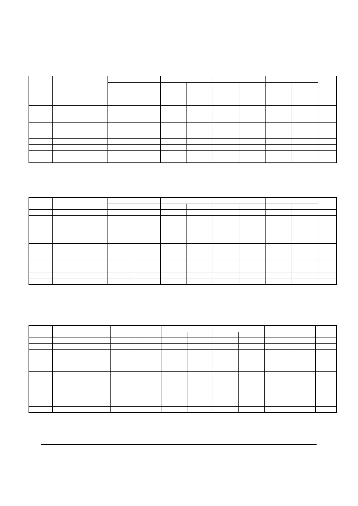
100K ECL DC Characteristics (V
EE
= -3.0V to -5.5V, VCC = GND)
-40°C 0°C 25°C 85°C
Symbol Characteristic
Min Max Min Max Min Max Min Max
Unit
VOH Output HIGH Voltage
2
-1045 -835 -995 -835 -995 -835 -995 -835 mV
VOH Output HIGH Voltage4 -1085 -880 -1025 -880 -1025 -880 -1025 -880 mV
VOL Output LOW Voltage
2,4
-1925 -1555 -1900 -1620 -1900 -1620 -1900 -1620 mV
VIH
Input HIGH Voltage
D/D¯, EN/EN¯¯ (PECL)
EN (CMOS/TTL)
-1165
V
EE
+2000
-880
V
CC
-1165
V
EE
+2000
-880
VCC
-1165
VEE+2000
-880
VCC
-1165
VEE+2000
-880
VCC
mV
VIL
Input LOW Voltage
D/D¯, EN/EN¯¯ (PECL)
EN (CMOS/TTL)
-1810
V
EE
-1475
VEE + 800
-1810
VEE
-1475
VEE + 800
-1810
VEE
-1475
VEE + 800
-1810
VEE
-1475
VEE + 800
mV
VBB Reference Voltage -1390 -1250 -1390 -1250 -1390 -1250 -1390 -1250 mV
I
IL
Input LOW Current EN
3
0.5 0.5 0.5 0.5
µA
IIH
Input HIGH Current EN
3
150 150 150 150
µA
IEE Power Supply Current1 48 48 48 54 mA
1. Specified with V
EEP
and CS-SEL open for VTL and VTX. Subtract 4mA for VTNA, VTNB & VTNC.
2. Specified with V
EEP
and CS-SEL connected to VEE for VTL and VTX only.
3. Specified with EN-SEL open for VTL and VTX only.
4. Specified with Q
HG
/Q¯HG connected with 50 Ω to VCC –2V for VTNA, VTNB & VTNC.
100K LVPECL DC Characteristics (V
EE
= GND, V
CC
= +3.3V)
-40°C 0°C 25°C 85°C
Symbol Characteristic
Min Max Min Max Min Max Min Max
Unit
VOH Output HIGH Voltage
1,3
2255 2465 2305 2465 2305 2465 2305 2465 mV
VOH Output HIGH Voltage
1,5
2215 2420 2275 2420 2275 2420 2275 2420 mV
VOL Output LOW Voltage
1,3,5
1375 1745 1400 1655 1480 1680 1400 1680 mV
VIH
Input HIGH Voltage
D/D¯, EN/EN¯¯ (PECL)
1
EN (CMOS/TTL)
2135
2000
2420
VCC
2135
2000
2420
VCC
2135
2000
2420
VCC
2135
2000
2420
VCC
mV
VIL
Input LOW Voltage
D/D¯, EN/EN¯¯ (PECL)
1
EN (CMOS/TTL)
1490
GND
1825
800
1490
GND
1825
800
1490
GND
1825
800
1490
GND
1825
800
mV
VBB Reference Voltage1 1910 2050 1910 2050 1910 2050 1910 2050 mV
I
IL
Input LOW Current EN
4
0.5 0.5 0.5 0.5
µA
IIH Input HIGH Current EN
4
150 150 150 150
µA
IEE Power Supply Current2 48 48 48 54 mA
1. For supply voltages other that 3.3V, use the ECL table values and ADD supply voltage value.
2. Specified with V
EEP
and CS-SEL open for VTL and VTX. Subtract 4mA for VTNA, VTNB & VTNC.
3. Specified with V
EEP
and CS-SEL connected to VEE for VTL and VTX only.
4. Specified with EN-SEL open for VTL and VTX only.
5. Specified with Q
HG
/Q¯HG connected with 50 Ω to VCC –2V for VTNA, VTNB & VTNC.
100K PECL DC Characteristics (V
EE
= GND, V
CC
= +5.0V)
-40°C 0°C 25°C 85°C
Symbol Characteristic
Min Max Min Max Min Max Min Max
Unit
VOH Output HIGH Voltage
1,3
3955 4165 4005 4165 4005 4165 4005 4165 mV
VOH Output HIGH Voltage
1,5
3915 4120 3975 4120 3975 4120 3975 4120 mV
VOL Output LOW Voltage
1,3,5
3075 3445 3100 3338 3100 3338 3100 3338 mV
VIH
Input HIGH Voltage
D/D¯, EN/EN¯¯ (PECL)
1
EN (CMOS/TTL)
3835
2000
4120
VCC
3835
2000
4120
VCC
3835
2000
4120
VCC
3835
2000
4120
VCC
mV
VIL
Input LOW Voltage
D/D¯, EN/EN¯¯ (PECL)
1
EN (CMOS/TTL)
3190
GND
3525
800
3190
GND
3525
800
3190
GND
3525
800
3190
GND
3525
800
mV
VBB Reference Voltage1 3610 3750 3610 3750 3610 3750 3610 3750 mV
I
IL
Input LOW Current EN
4
0.5 0.5 0.5 0.5
µA
IIH Input HIGH Current EN
4
150 150 150 150
µA
IEE Power Supply Current2 48 48 48 54 mA
1. For supply voltages other that 5.0V, use the ECL table values and ADD supply voltage value.
2. Specified with V
EEP
and CS-SEL open for VTL and VTX. Subtract 4mA for VTNA, VTNB & VTNC.
3. Specified with V
EEP
and CS-SEL connected to VEE for VTL and VTX only.
4. Specified with EN-SEL open for VTL and VTX only.
5. Specified with Q
HG
/Q¯HG connected with 50 Ω to VCC –2V for VTNA, VTNB & VTNC.
 Loading...