

Page 1
Technical information
T E M P O
Avda. San Silvestre, s/n
31350 Peralta (Navarra) Spain
Tel.: +34 948 709 709
www.sat.azkoyen.com
Page 2

1ª 10012 - E 02 - 2006
2
I N D E X
1. INTRODUCTION
1.1. DEFINITIONS
1.2. RANGE
1.3. PRINCIPLE TECHNICAL CHARACTERISTICS
2. DESCRIPTION OF COMPONENTS
2.1. PRINCIPLE COMPONENTS
2.2. HYDRAULIC CIRCUIT FOR ESPRESSO COFFEE
2.3. HYDRAULIC CIRCUIT FOR INSTANT PRODUCTS
3 INSTALLATION AND SWITCHING ON
3.1. UNPACKING
3.2. SWITCHING ON
3.3. ERROR MESSAGES SHOWN ON THE DISPLAY
3.4. CONTROL POINTS
4. CLEANING AND MAINTENANCE
5. WORKING CONDITIONS AND NORMS
6. DIMENSIONS
Page 3
1ª 10012 - E 02 - 2006
3
1. INTRODUCTION
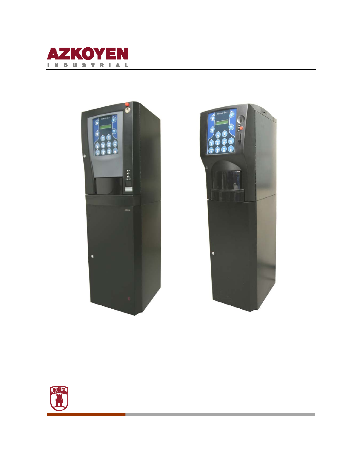
The automatic vending machines in the TEMPO range are destined to the elaboration and sale
of espresso coffee and instant beverages that consist of the mixture of hot water and soluble
powder or granules. The product is served in a plastic cup.
In the rest of this document the following elements will be called:
The machines in the
TEMPO
range, machine or machines. The
espresso coffee infusion element, infusion element. The electro valve, EV or
EVs
1.1. DEFINITIONS
Espresso coffee: infusion of coffee elaborat ed according to the following conditions:
- 7 g of ground coffee.
- The temperature of the infusion water between 92º C and 96º C.
- The water pressure at 8 kg/cm².
- The infusion time of the coffee between 20 and 28 seconds.
- The volume of water in the infusion 40 ml.
Volume dosage: this do sage system measures the volume of water that is used for the
espresso infusion.
Water pump: an electro magnetic system for pumping the infusion water and giving it the
correct pressure.
Infusion: this is the name given to the process of passing hot water through the ground
coffee to extract its oils and essences.
- Volumetric infusion: when the process of infusion uses a constant volume of water.
Coffee tablet: the residual compressed coffee grounds after the infusion process.
Programming mode: when the machine is ready for any of its functions or parameters to be
programmed.
Working mode: when the machine is in the working state and ready to prepare any of the
services it offers.
Page 4
1ª 10012 - E 02 - 2006
4
1.2. RANGE
The TEMPO range is comprised of the M, Mz, L and Lz series. The cabinets of the Mz and Lz
series are narrower than those in the M and L series. Each of the four series have models that
elaborate espresso coffee and instant products.
• The models with espresso coffee elaborate instant products as well.
• The models with instant products only elaborate instant products
• The L range has a Fresh brew model destined to the elaboration of tea infusions
1.3. PRINCIPLE TECHNICAL CHARACTERISTICS
Ô Super automatic function: the press of a button is sufficient to elaborate a
magnificent espresso coffee.
Ô It grinds the coffee at the moment it is ordered.
Ô
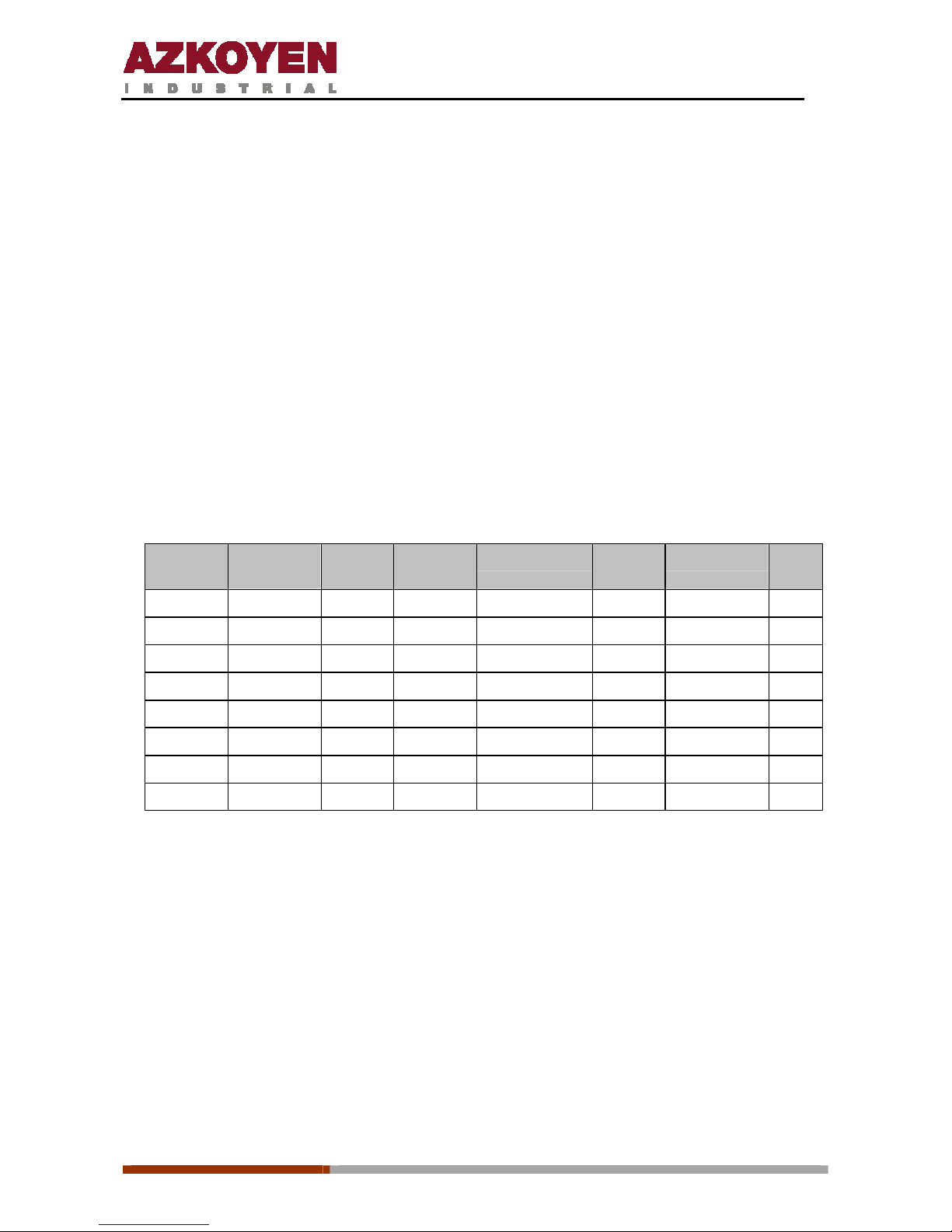
Products that each machine can elaborate:
Tempo Coffee
beans
Sugar Instant
coffee
Decaffeinated Milk Chocolate Tea
MI
Yes Yes Yes Yes
ME Yes Yes Yes Yes
MzI
MzE
LI
Yes Yes Yes Yes Yes Yes
LE
LzI
LzE Yes Yes Yes Yes Yes
Ô The water temperature is programmable.
Ô The ground coffee dose is programmable between 5 g and 8 g.
Ô The switching on and off of the machine is automatic and programmable.
Ô Water pump for water pressure incorporated in the machine.
Ô Volume dosage of water in the different espresso coffee services is programmable.
Ô The infusion element is thermo compensated.
Page 5
1ª 10012 - E 02 - 2006
5
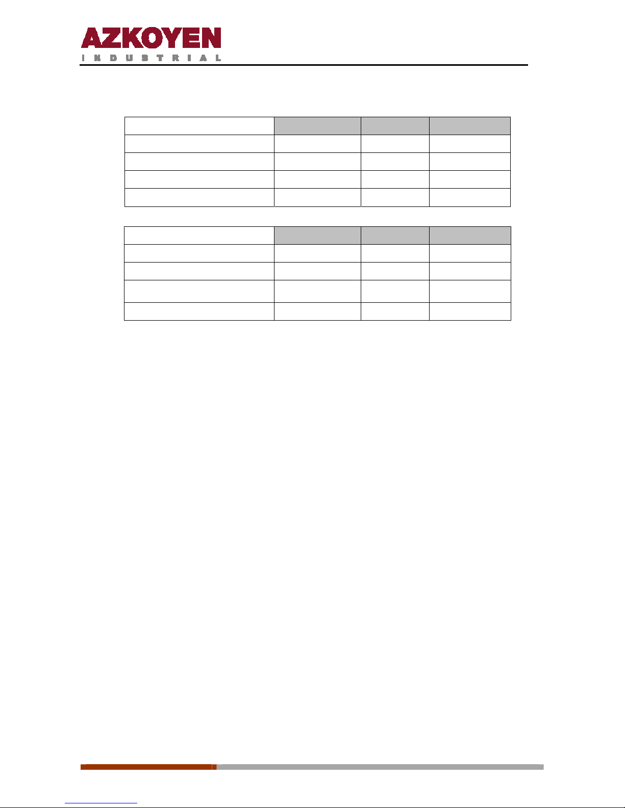
Ô Power supply:
TEMPO instant
Voltage Power Length
Mains voltage 230 Vac / 50 Hz
Heating element 230 Vac / 50 Hz 1500 W
Average daily consumption 3500 W
Mains flex 3700 mm
TEMPO espresso Voltage Power Length
Mains voltage 230 Vac / 50 Hz
Heating element 230 Vac / 50 Hz 1500 W
Average daily consumption
3000 W
Mains flex 3700 mm
Page 6
1ª 10012 - E 02 - 2006
6
2. DESCRIPTION OF COMPONENTS
2.2. PRINCIPLE COMPONENTS
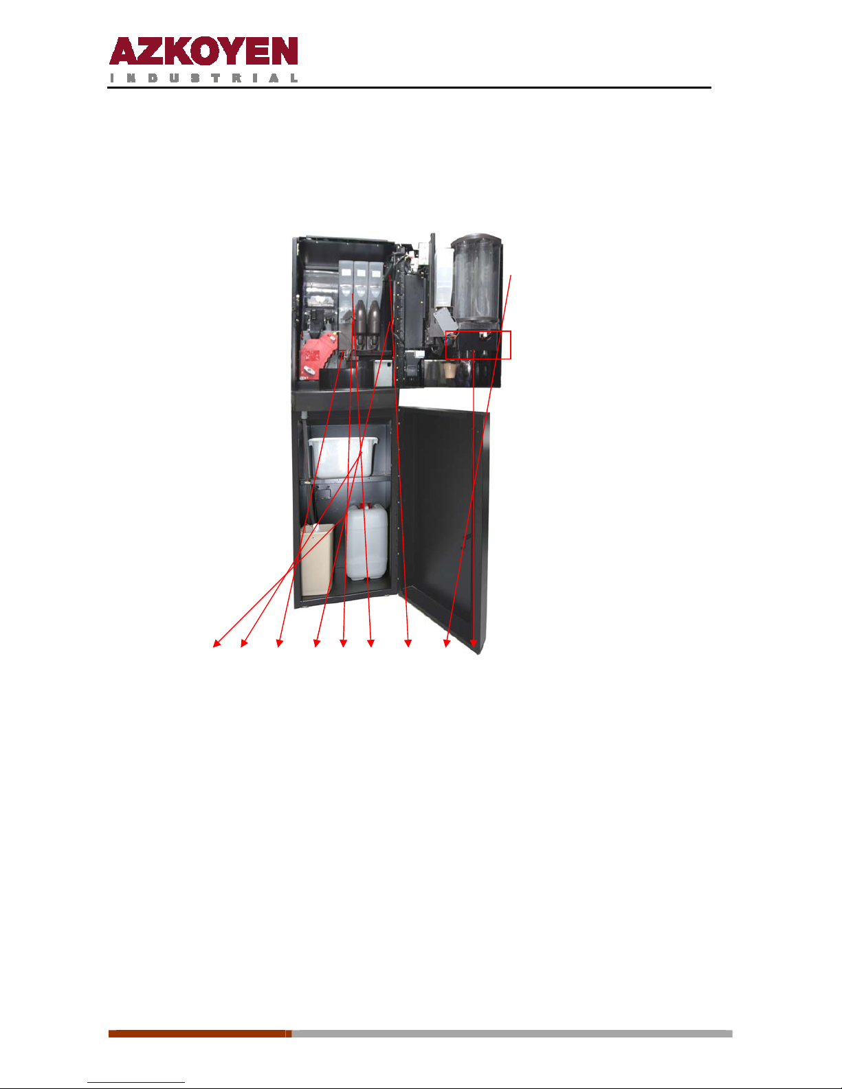
A1 A2 A3 A4 A5 A6 A7 A8 A9
A1. Residue liquid bucket
It collects all the residue liquids that the machine generates. It has a capacity of 8 litres.
When
it reaches a determined level a float device is activated to put the machine out of order
until it
is emptied.
A2. Coffee residue bucket
It collects the solid residue that the machine generates. It has a capacity for the residue of
7500 grams of ground and elaborated coffee beans.
Page 7
1ª 10012 - E 02 - 2006
7
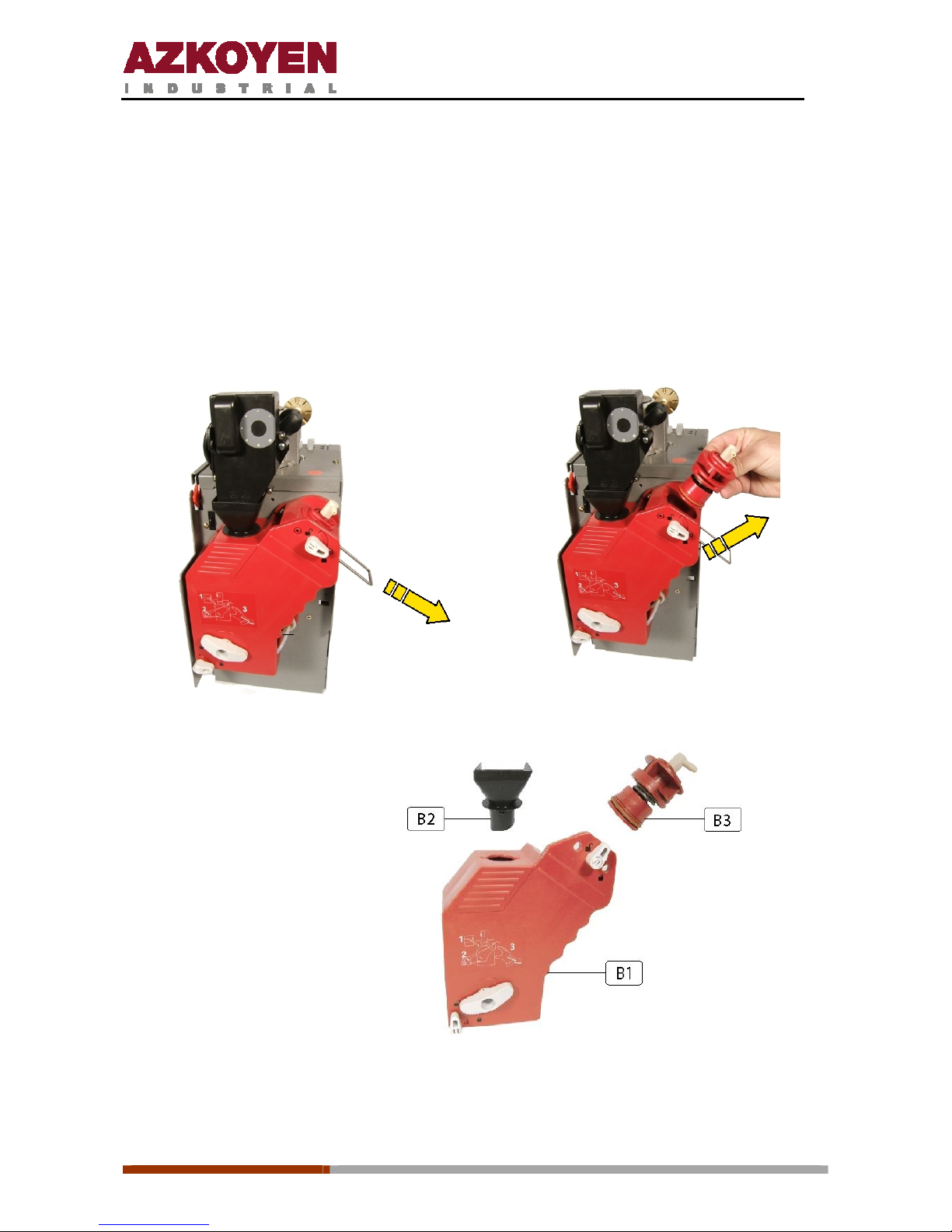
A3. Infusion element
Made of resin, it is the element that the machine uses to make the espresso coffee.
Between the piston and its support there is a spring and a espacer that, depending how it is
placed, will vary the capacity of ground coffee the chamber w il l hold.
The spacer should be placed between the piston and its support when the dosage is set for 5
to 6.5 g of ground coffee. When the dosage is set for 7 to 8 g of ground coffee, the space
should be placed on the piston support.
Pu
ll
out the clip
Remove the piston
B1.
Infusion element inferior
B2.
Loading funnel
B3. Pistón
Page 8
1ª 10012 - E 02 - 2006
8
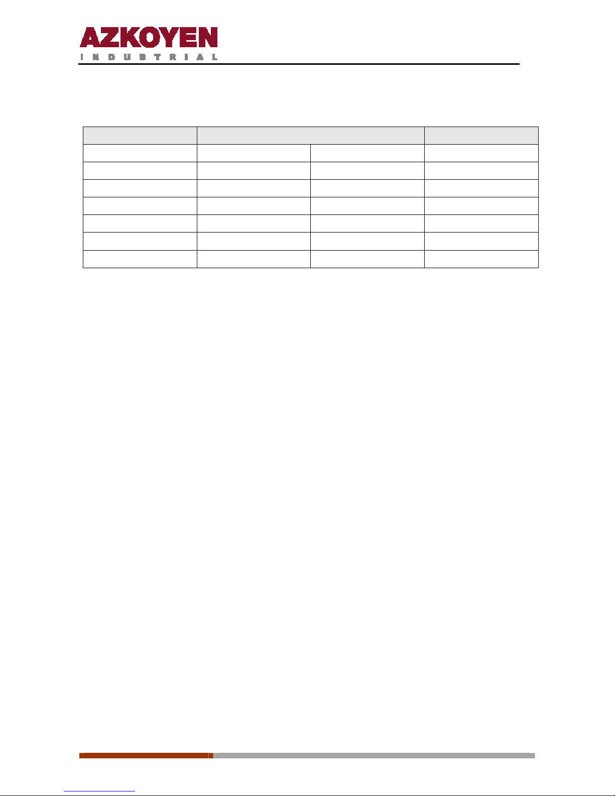
The possible regulation of the capacity of the infusion element, using the washer, and the
position of the dosage handle are shown in the table below:
Dose Piston washer position Dosage position
5 g Under 1
5.5 g
Under
2
6 g
Under
3
6.5 g
Under
4
7 g
Over
5
7.5 g
Over
6
8 g
Over
7
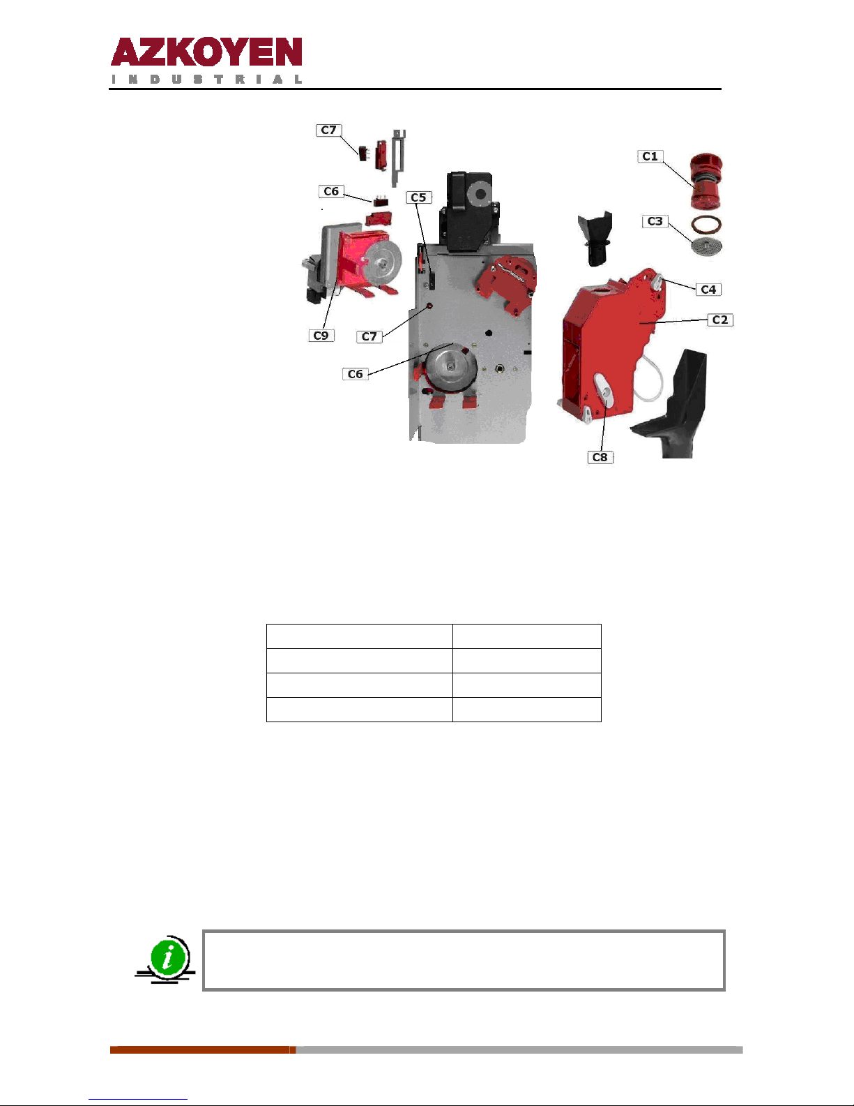
The infusion element has moving parts that are activated by a 24 Vdc motor that moves a
crank which moves the coffee from the dosage element to the piston. At the same time it also
moves a lever that activates a micro switch; this indicates the position of the infusion element
to the control board.
At rest, the infusion element cannot move from its position as it is held by the piston. Before
extracting the piston the black extraction button (C7) should be pressed (with the machine
switched on). On pressing the extraction button the infusion element wil l position itself in t he
coffee loading position. After this the two levers that hold it can be turned and it can be
removed with ease.
In the infusion element support there is another micro switch that deactivates when the
infusion element is removed. This wa y, the control bo ard knows wheth er the infusion element
is correctly positioned or not.
To replace the infusion element into the machine it may be in any position and it does not
matter if it moves while out of the machine. It only needs to be replaced and the two holding
levers fixed. When the presence micro switch is activated, the infusion element motor will
position it correctly.
Page 9
1ª 10012 - E 02 - 2006
9
C1. Piston
C2. Spring
C3. Washers
C4. Infusion element
C5. Lever
C6. Holding handle
C7. Extraction button
C8. Position micro switch
C9. Presence micro switch
C10. Infusion element
movement handle
C11. Filter
A4. Beaters
The mixing of the products with hot water from the boiler is done with these elements.
Technical characteristics:
Make of motor
Mabuchi
Voltage
24 Vdc
Power
20 w
Speed
16 rpm
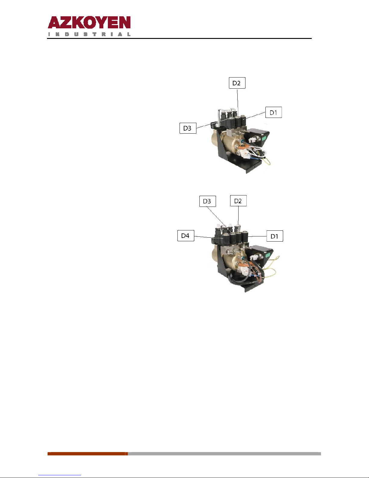
The EVs of the instant beverages are an important part of the beating process. They control
the hot water from the boiler to the beaters for the elaboration of the instant beverages.
They are fitted to a thermo compensated brass support that provides a constant temperature
by means of a tube through which hot water from the boiler flows. This circulation is produced
by convention; the water cools in the brass support and drops while the hot water from
the boiler enters at the top. This way, during the elaboration of the instant beverages, the
hot water that goes to the beaters does not suffer excessive temperature losses.
The working voltage of the EVs is 24 Vdc
Maximum pressure they accept is 15 Kg/cm²
Page 10
1ª 10012 - E 02 - 2006
10
The EVs are positioned horizontally and correspond to the following products:
Tempo ME
D1.
Decaffeinated
D2. Coffee
D3. Milk y chocolate
Tempo MI
D1. Coffee and decaffeinated
D2. Milk
D3. Chocolate
Tempo LE
D1. Descafeinado
D2. Milk and chocolate
D3. Coffee
D4. Tea
Tempo LI
D1. Tea
D2. Chocolate
D3. Milk
D4. Coffee and decaffeinated
Order of the EVs looking from the exterior of the machine
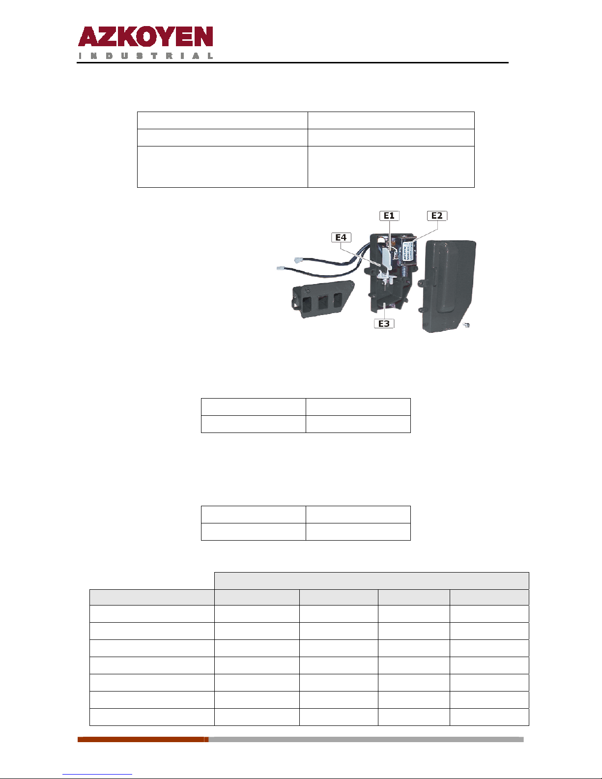
A5. Ground coffee dosage element
Situated on the side of the grinder, its function is to measure the quantity of ground coffee for
each service, and later put a dose into the infusion element.
The principle function is based on a moving wall that the ground coffee moves and a micro
switch th at is activate d by the mov ing wall. On activating the micro switch, the grinder stops
and the EV drops the ground coffee into the infusion element.
Page 11
1ª 10012 - E 02 - 2006
11
Technical characteristics:
Voltage 24 Vdc
Regulation Minimum 5g and maximum 8g
Regulation lever 7 points: Point 1 is 5 g
Point 7 is 8 g
E1. Micro switch
E2. Solenoid
E3. Micro activated flap
E4. Regulation lever
A6. Coffee bean hopper
The capacity is:
Series ME
1.3 kg
Series LE 2.2 kg
A7. Instant product hoppers
The capacities are:
Series ME and MI
1.6 litres
Series LE and LI
3 litres
The approximate weight of the product is:
Capacity in grams
Product
Series ME Series MI Series LE
Series LI
Instant coffee
280 280 525 525
Decaffeinated coffee
280 280 525 525
Milk
700 700 1300 1300
Chocolate
800 800 1500 1500
Tea
1000 1000 2000 2000
Soup
1600 1600 3000 3000
Sugar
1400 1400 2600 2600
Page 12
1ª 10012 - E 02 - 2006
12
A8. Programming box
This element is used for programming the machine.
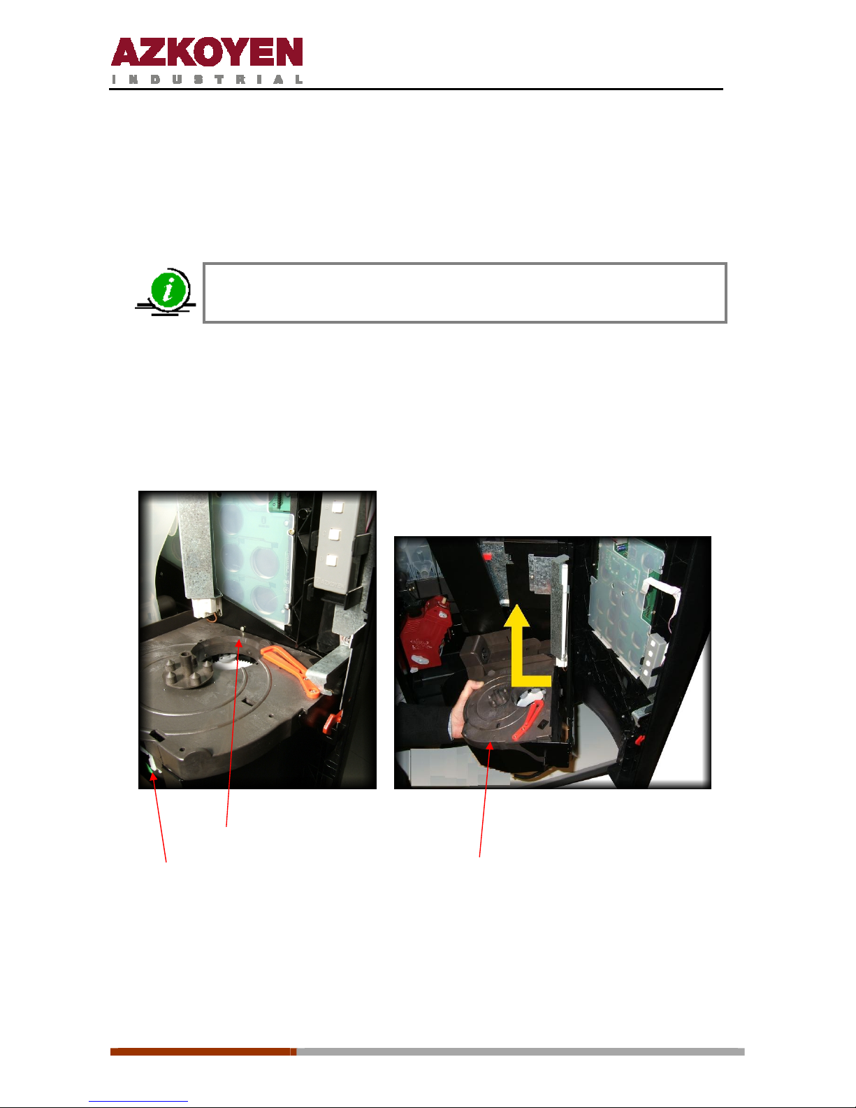
A9. Extractor systems for cups, sugar and spoons
The three systems are mounted in the one support.
The MI and LI series, standard, do not have a container for spoons
To remove the extractors from the machine, fo llow these steps:
1st Disconnect the wiring loom from the cup extractor board.
2nd Unscrew the screws indicated in the photo.
3rd Pull the extractors upwards until freeing them from the clips in the support.
screw
Wiring Cup extraction system
Tempo door: cup extraction system disassembly
First the wiring loom should be disconnected by removing the cover that protects the cup
extractor. The sugar and spoon extractor can be separated from the cup extractor by freeing
the clip indicated in the photo and pulling upwards.
Page 13
1ª 10012 - E 02 - 2006
13
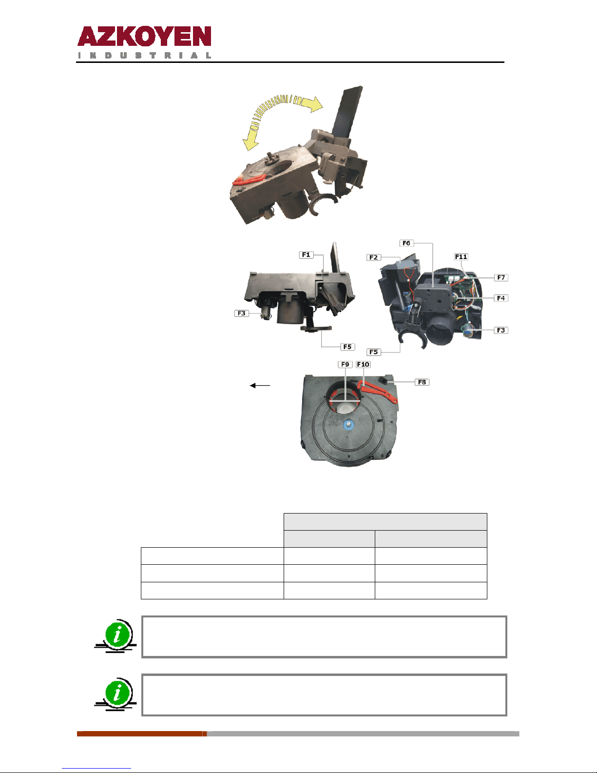
F1.
Clip
F2.
Sugar and spoon extractor motor
F3.
Cup extractor motor
F4.
Cup container movement motor
F5.
Cup support arm
F6.
Cup arm motor
F7.
Control board
F8.
Cup extraction button
F9.
Cup presence photocells
F10.
Hopper position micro
F11.
Sugar and spoon extractor
connector
Cup extractor characteristics:
Cup container
ME and MI Series LE, LI and LFB Series
Quantity
500
700
Ø of cups
70 to 71 mm
70 to 71 mm
Voltage to motor
24 Vdc
24 Vdc
There is a cup extractor designed for cups of 73 mm.
The cups should be opaque so the infrared detectors can detect them
Page 14
1ª 10012 - E 02 - 2006
14
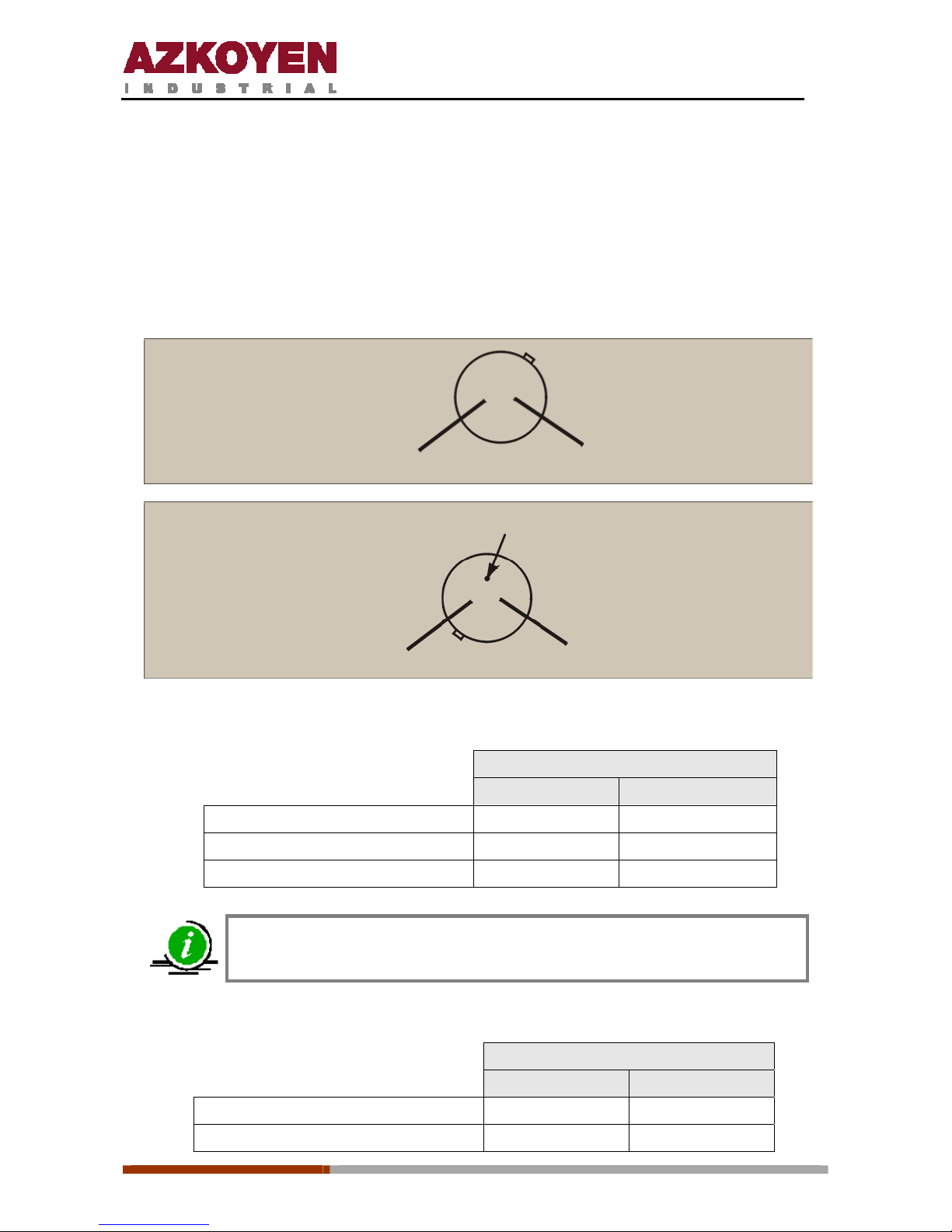
• The cup container is divided into 5 separate columns. When one of them runs out of cups,
the motor turns the container until the next column is situated over the extractor. After the
motor turns for 6.5 seconds and the photocells do not detect a new column of cups, the
machine will go out of order an d the display will show “Out of cups”.
• The cup container holder has a button to extract a cup when it is pressed.
• The electrical connections for the infrared photocell terminals that are used to detect the
cups are:
Spoon extractor characteristics:
Spoon container
ME and MI Series LE, Li and LFB Series
Quantity 250 350
Standard spoon measurement 90 x 9 x 1.5 mm 90 x 9 x 1.5 mm
Motor voltage 24 Vdc 24 Vdc
There is a Spoon extractor designed for spoons of 110 x 9 x 1.5 mm
Sugar extractor characteristics:
Sugar extractor
ME and MI Series LE and LI Series
Capacity 1400 2600
Motor voltage 24 Vdc 24 Vdc
PHOTODIODE
ANODE
CATHODE
RED
(Detection of cups)
BROWN
(Detection of cups)
TERMINAL CUT
PHOTOTRANSISTOR
COLLECTOR
EMITTER
YELLOW
(Detection of cups)
BLACK
(Detection of cups)
Page 15
1ª 10012 - E 02 - 2006
15
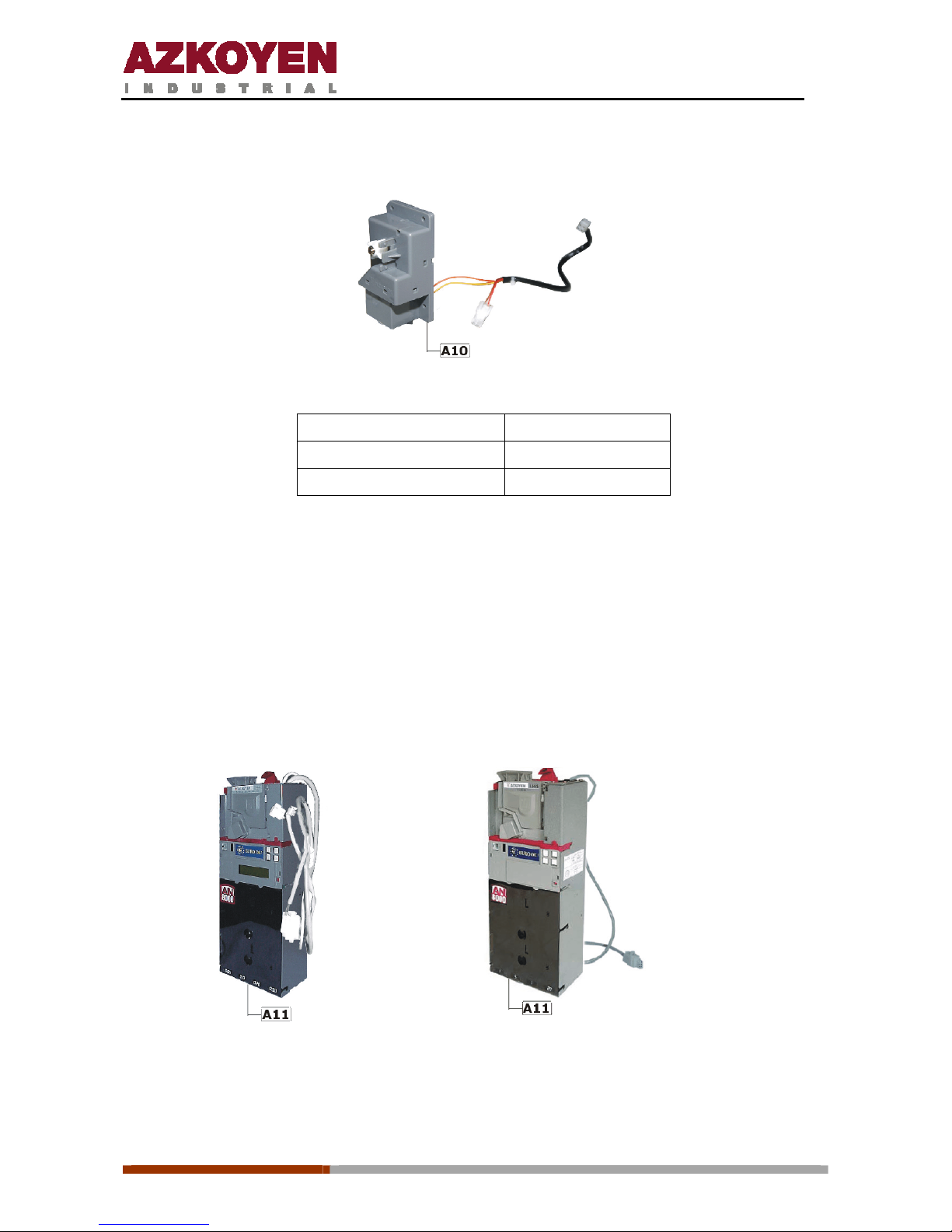
A10. Product extractors
Technical characteristics:
Motor manufacturer Mabuchi
Voltage 24 Vdc
Speed 40 rpm
A11. Coin system
All the models in the TEMPO L range use coin changers with Executive or MDB
communication protocol.
The models in the TEMPO M range use a coin validator. It is always “exact amount”; no
change given.
On the left of the door there is a space for the coin changer which is held with three screw s.
The connectors are situated on the upper part. When the machine is connected, it will
automatically detect if it has a coin changer with MDB or Executive communication protocol.
Executive coin changer MDB coin changer
Page 16
1ª 10012 - E 02 - 2006
16
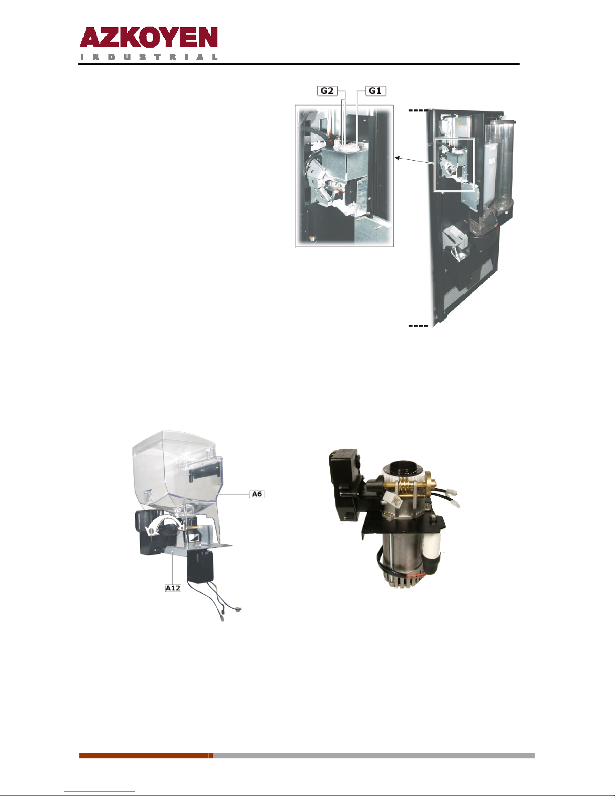
G1. Conector for MDB communication protocol coin
system
G2. Conectors for communication executive
protocol coin system
A12. Coffee grinder
It has the model M03 from Azkoyen installed, although before they had the grinder from
Componenti installed
Componenti M03
Page 17
1ª 10012 - E 02 - 2006
17
Technical characteristics:
Componenti M03
Voltage 230 Vca 230 Vca
Nominal power 65 w 350 w
Speed 1.250 rpm 1390 rpm
Diameter of the grinders 45 mm 63 mm
Grind points 0,026 mm 0,026 mm
Moving the handle anticlockwise gives a coarser grind and moving it clockwise gives a finer
grind.
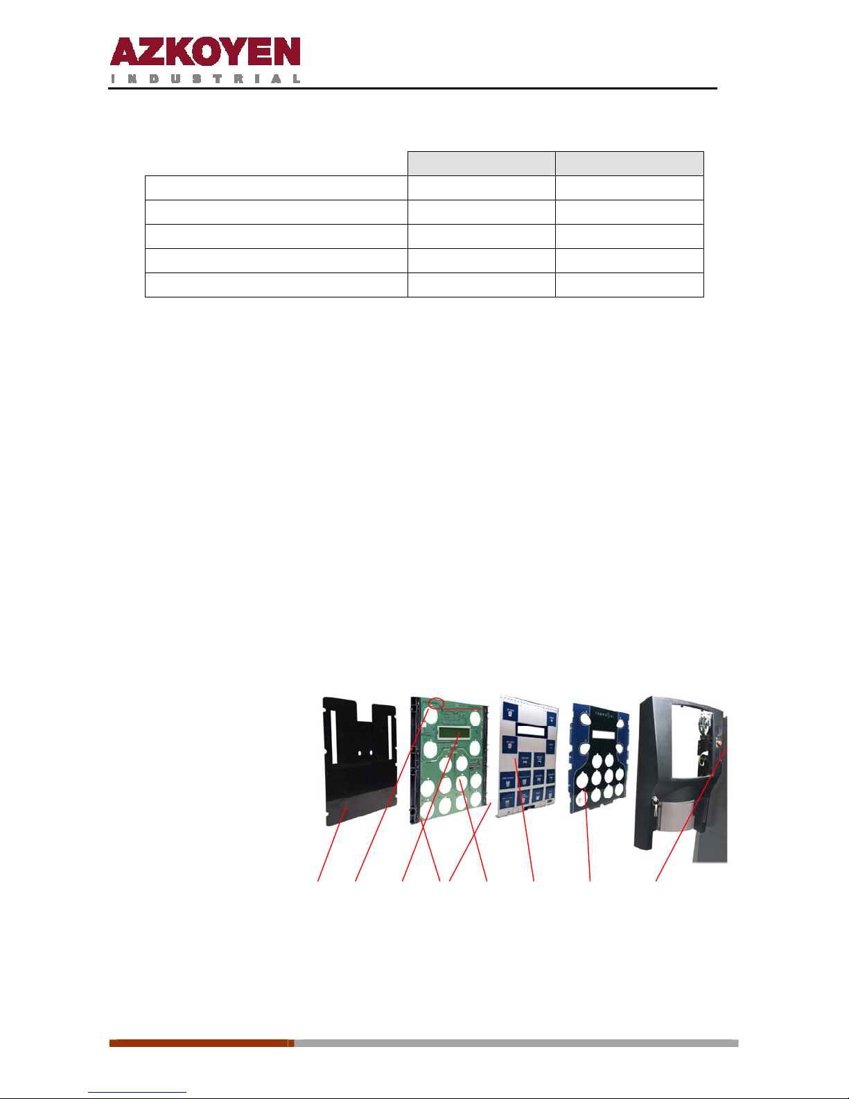
A13. Button panel and display
These machines have an innovative system for the product selection buttons. The system is
based on capacitive detection. To request a product it is not necessary to actually press the
button, it is enough to put your finger near the button and the machine will detect its presence
and start the elaboration of the requested beverage. All the product selections have a red led
diode that lights when the machine is e laborating that beverage. There is a pan el with a labe l
of all the available products in the machine between the Perspex protection and the circuit
board of the buttons.
On the circuit board there is also an alphanumeric display with two 16-character lines.
The panel with the product labels can be removed by pulling downwards. It is held
between two grooves on both sides of the circuit board so to replace it is necessary to
insert it in the grooves.
H1.
Reject button
H2. Exterior panel
H3.
Product labels
H4.
Button circuit board
H5.
Grooves for product labels
H6. Display
H7. Leds
H8. Protector
H8 H7 H6 H5 H4 H3 H2 H1
To help in the process of fitting the product label panel, the button circuit board that is held
with eight screws can be removed.
Page 18
1ª 10012 - E 02 - 2006
18
A14. Product door
Made of polycarbonate, its main purpose is to prevent the entry of insects in to the machine. It
can be removed by removing the holding plate on the interior of the machine.
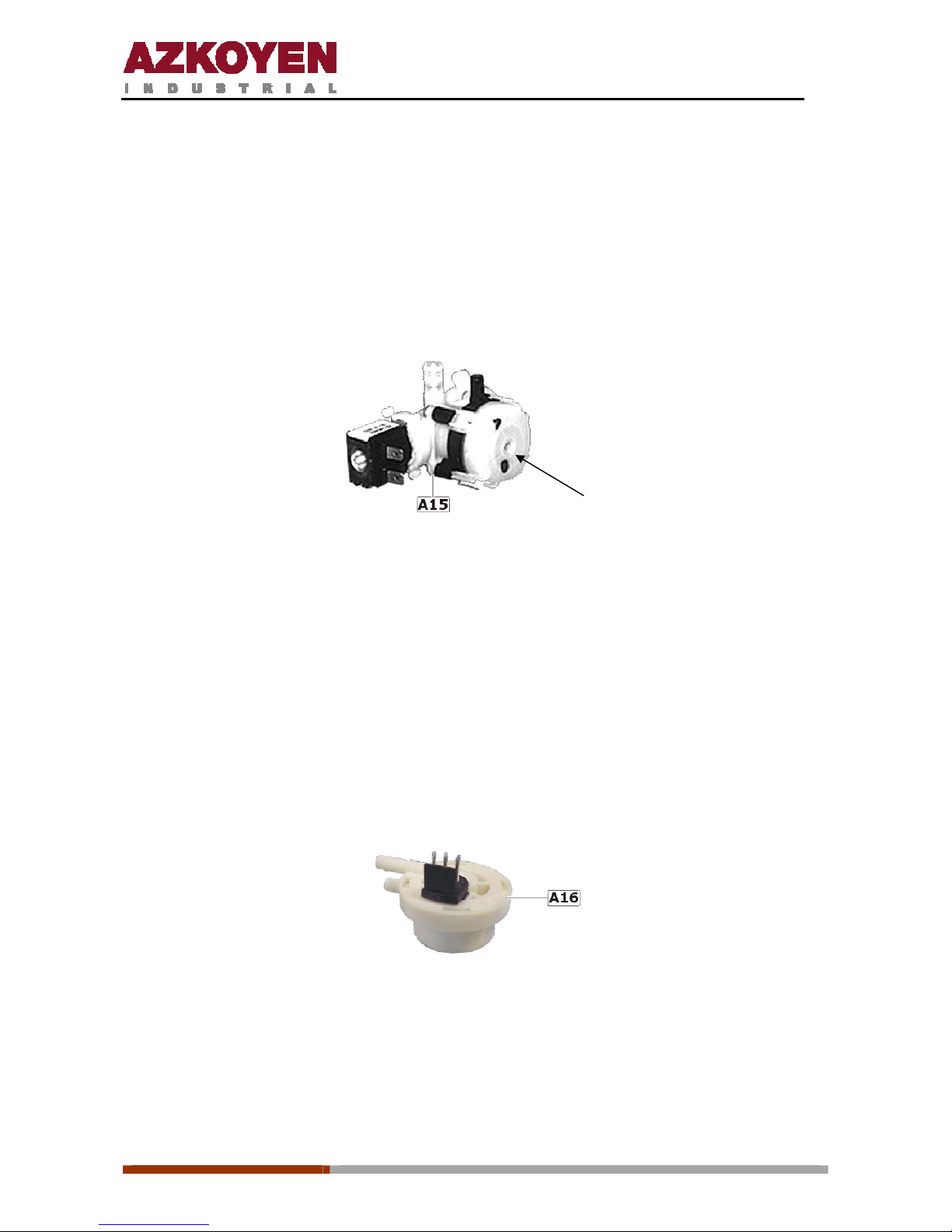
A15. Water inlet EV
It allows the entry of water from the mains to the cold water deposit. It works at 230 Vac.
This
EV is only fitted to machines th at are connected to the mains water supply.
unblock
It has a security block system for cases where, for lime scale or any solids from the main
water supply, the EV does not close properly. This system activates when the level in the
residue bucket is excessively high.
To unblock the EV, switch off the water pressure from the mains. If this is not possible, tap the
EV with a blunt object, for example an Allen key, on the inside of the hole on the top part of
the EV as shown in the photograph.
It you may also unblock the EV by tapping it with something like the handle of a screw driver.
A16. Volumetric counter
Its function is to measure the quantity of water that is pumped for the elaboration of the
espresso coffee.
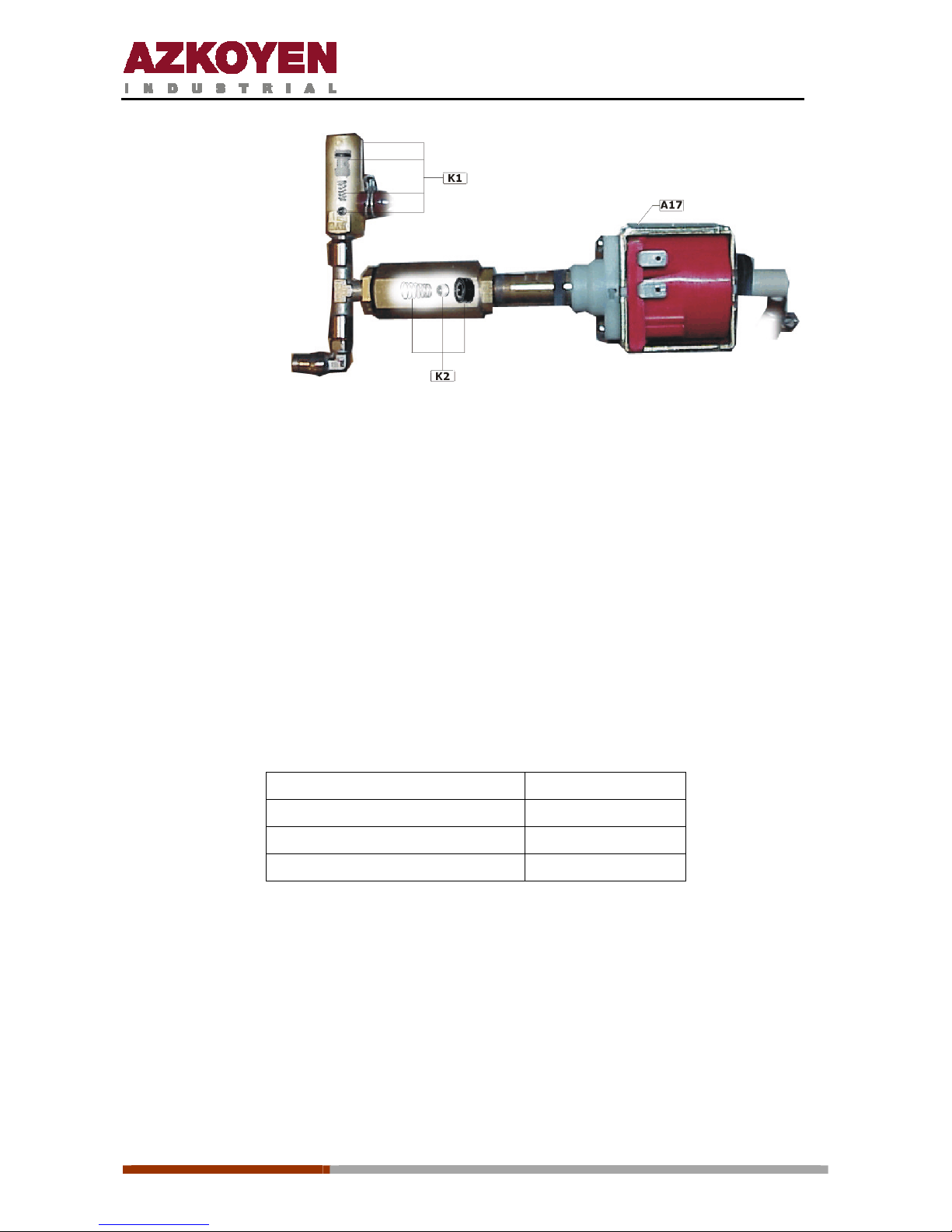
A17. Water pump
This element has the job of pumping water from the cold water deposit to the hot water boiler;
the cold water pushes the hot water towards the EVs for the instant products or towards the
infusion element for making espresso coffee.
Page 19
1ª 10012 - E 02 - 2006
19
K1. By-pass
K2. Anti return valve
When an espresso coffee is elaborated, the water pressure needed is quite high to be able to
pass through the compressed ground coffee in the infusion element. This resistance the coffee
offers makes the water pressure in the boiler increase up to a pressure of 9 Kg/cm². At this
pressure the by-pass (2) opens allowing a small amount of water to return; sufficient to
prevent the water pressure from going over the 9 Kg/cm².
The by-pass is a small hole covered with a ball that is h eld in place by a spring. This spring
will hold a pressure of 9 Kg/cm², but over this pressure it compresses and allows the
water to pass.
The pressure of 9 Kg/cm² is considered the ideal for elaborating espresso coffee.
When the instant beverages are elaborated, there is no resistance offered and so during there
elaboration the water pump works at lower pressures than when elaborating espresso coffees.
Technical characteristics:
Voltage Pulsing 110 V
Power 70 w
Working pressure 8 Kg/cm²
Maximum pressure 12 Kg/cm²
The pump has an anti return valve that prevents the return of water from the boiler.
Page 20
1ª 10012 - E 02 - 2006
20
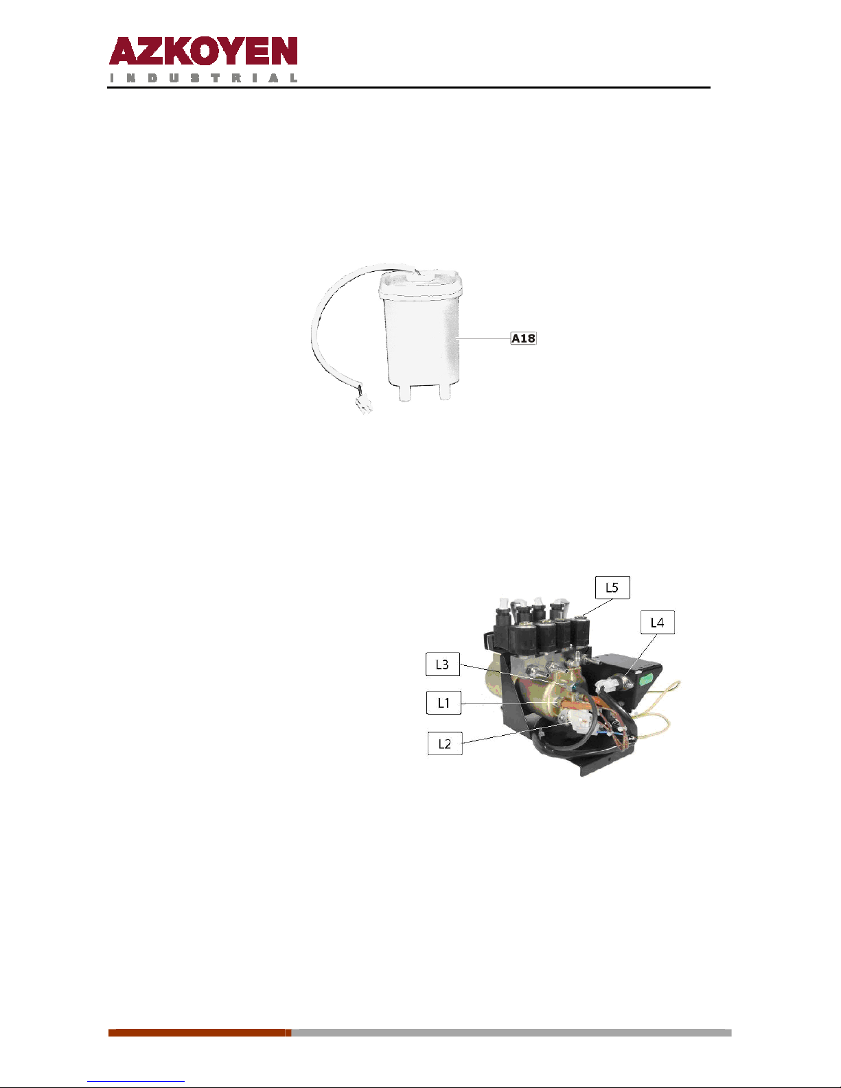
A18. Cold water deposit
Made of polypropylene, It has the capacity of 500 cc. It is at atmospheric pressure
and temperature. From this deposit is taken the water to elaborate the espresso coffee and
instant beverages.
The water level in the deposit is controlled by a float that activates a magnetic sw itch.
A19. Hot water boiler
The boiler works under pressure and has a capacity of 0.5 litres of water. The water for
elaborating espresso coffee and instant beverages is heated in this deposit.
L1.
1500 W heating element
L2.
Security thermostat 120º C
L3.
Temperature sensor (PTC)
L4. Triac
L5. Electrovalves
The boiler is made of brass and does not need any device to control th e level of water as the
boiler fills automatically from the moment the machine is switched on. After this the water that
is used is replaced with water from the cold deposit so the boiler is always full.
There are three outlets; one through a 3-way EV for the elaboration of espresso coffee. This
EV has an outlet from the boiler, another goes to the infusion element, and the third that, at
rest, allows the infusion element to be at atmospheric pressure.
Page 21
1ª 10012 - E 02 - 2006
21
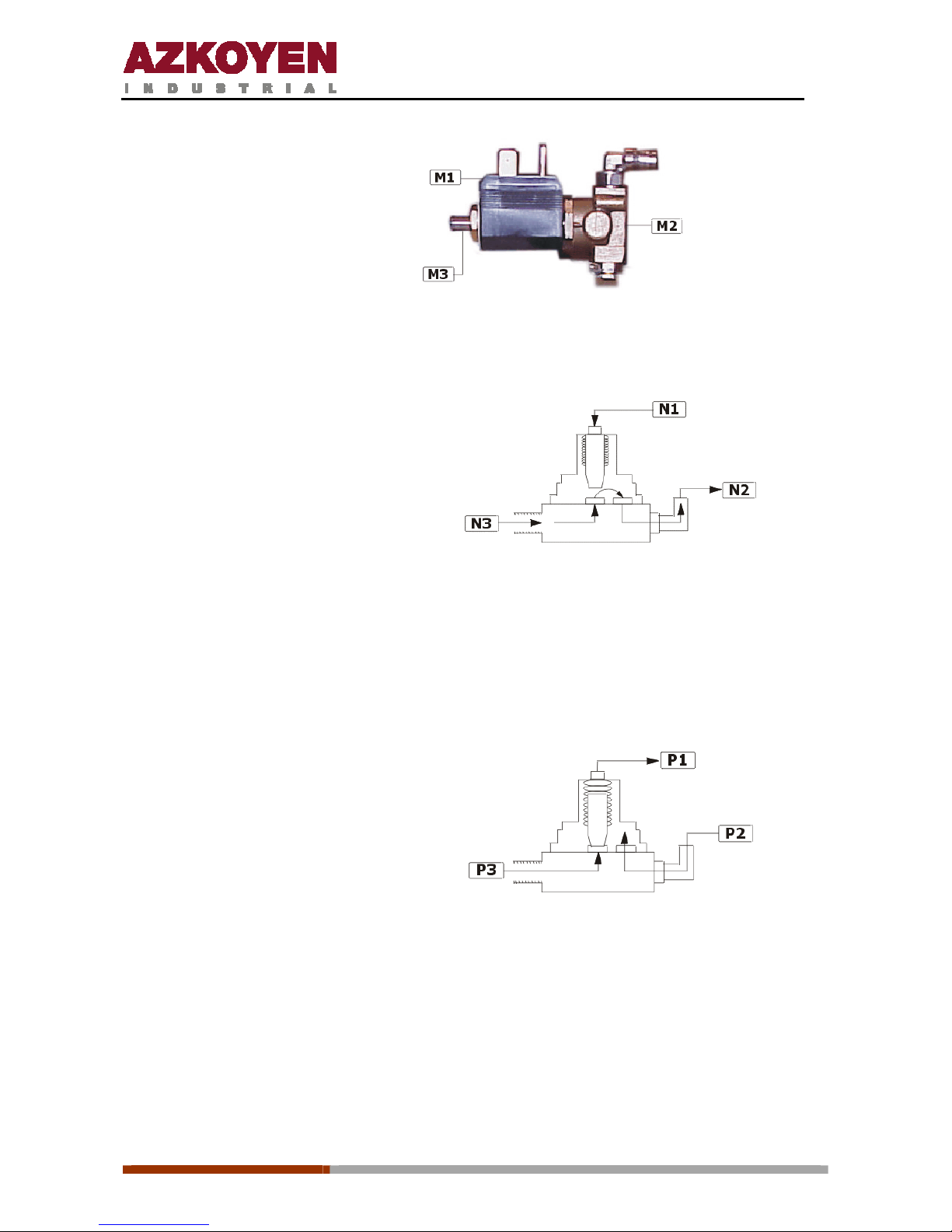
M1. Solenoid
M2. Valve
M3. 3º outlet
When the machine is in the espresso coffee making process, the third is closed while the
outlet from the boiler and the inlet to the infusion element are open to each other.
N1.
3
rd
closed
N2.
To the infusion element
N3.
From the boiler
When the machine finishes elaborating an espresso coffee, the EV goes to rest state and
closes the outlet from the boiler leaving the infusion element open to the third outlet. In this
way the water that did not pass through the coffee and was retained in the infusion element
goes out through the third outlet to the residue bucket.
The water recedes back from the infusion element towards the third outlet because of the
pressure it was submitted to by the pump in the infusion process.
P1. 3ª
open
P2.
Infusion element joined to atmospheric
pressure
P3.
Boiler water closed
The other two outlets are connected to the instant beverage EV. When the machine is at
rest, these outlets allow the circulation of water, through convection, between the boiler
and the brass support of the instant beverage EV. This way the support is thermo
compensated and the water that reaches the beaters is always at the correct temperature.
Page 22
1ª 10012 - E 02 - 2006
22
Technical characteristics:
Heating element voltage 230 Vac
Power 1.500 w
Temperature programming 40 a 99º C
Safety protection with manual reset 120º C
Voltage of EVs 24 Vac
Power of instant EV 8 w
Power of espresso coffee 10 w
Maximum pressure of EVs 15 Kg./cm²
Working temperature of EVs
-10º C a 140º C
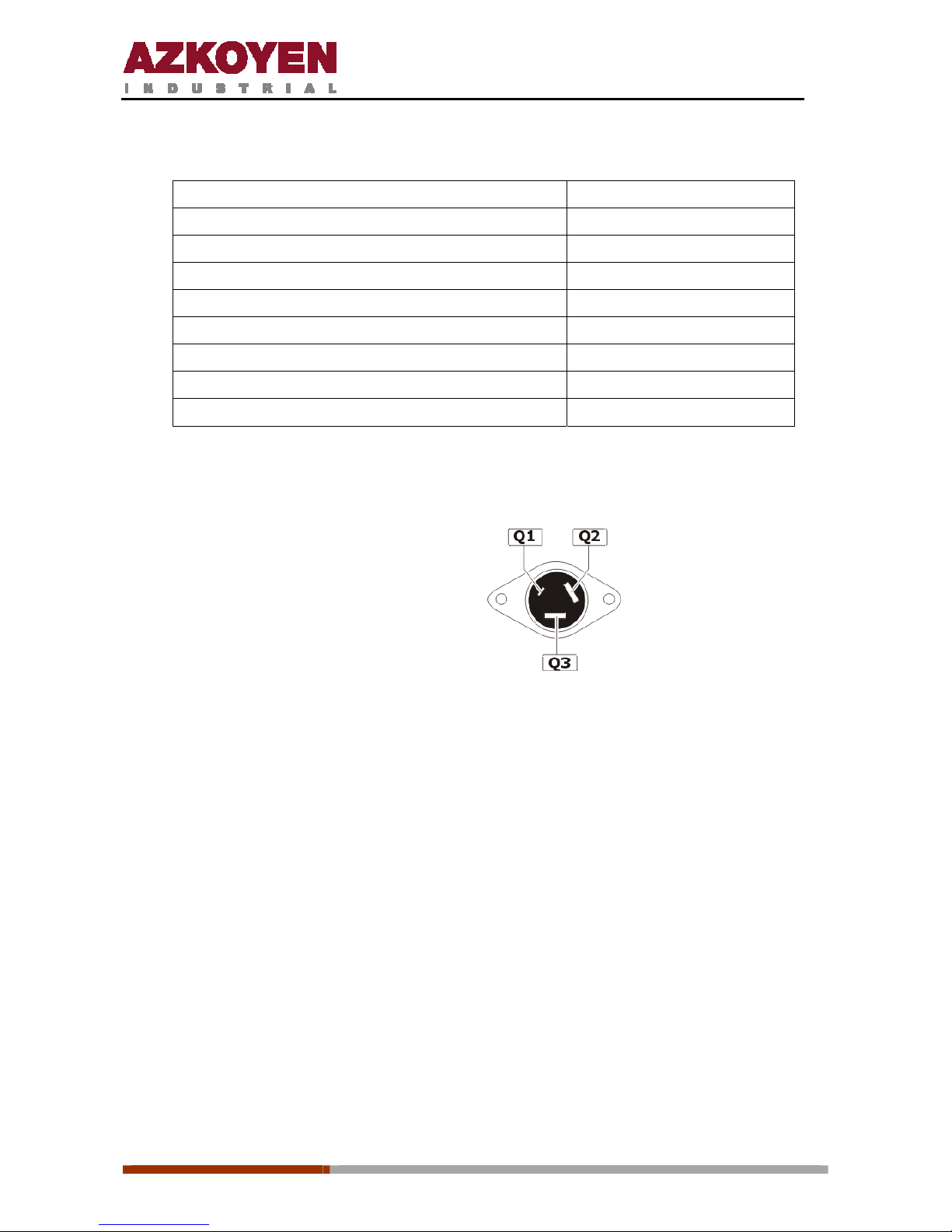
Control of the heating element is done wit h a triac that is situated on the boiler support.
Always respect the position of the connection cables.
Q1. White
Q2. Black
Q3. Brown
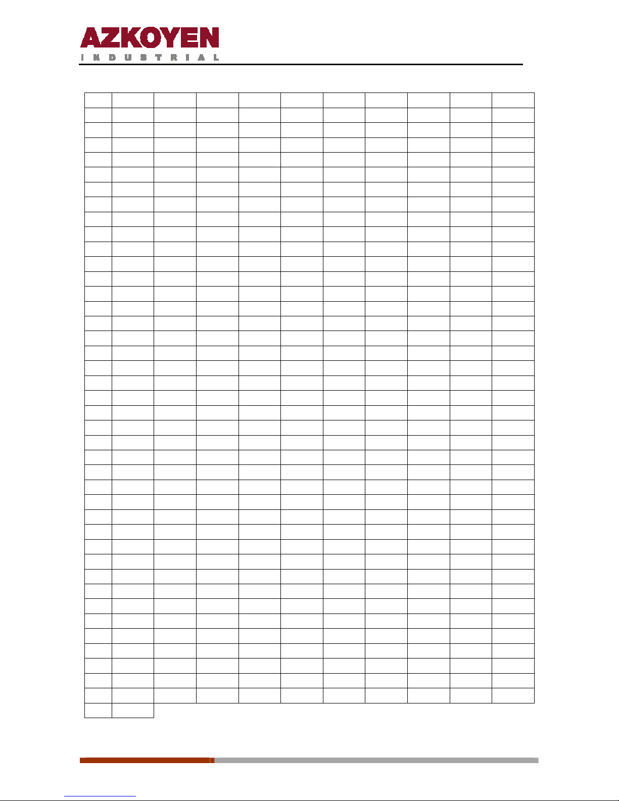
Temperature control of the water in the boiler is done with a PTC100. The following
table shows the resistance values that the PT100 gives according to the temperature
that it is submitted.
Page 23
1ª 10012 - E 02 - 2006
23
ºC 0 1 2 3 4 5 6 7 8 9
0 100,00 100,39 100,78 101,17 101,56 101,95 102,34 102,73 103,12 103,51
10 103,90 104,29 104,68 105,07 105,46 105,85 106,24 106,63 107,02 107,40
20 107,79 108,18 108,57 108,96 109,35 109,73 110,12 110,51 110,90 111,28
30 111,67 112,06 112,45 112,83 113,22 113,61 113,99 114,38 114,77 115,15
40 115,54 115,93 116,31 116,70 117,08 117,47 117,85 118,24 118,62 119,01
50 119,40 119,78 120,16 120,55 120,93 121,32 121,70 122,09 122,47 122,86
60 123,24 123,62 124,01 124,39 124,77 125,16 125,54 125,92 126,31 126,69
70 127,07 127,45 127,84 128,22 128,60 128,98 129,37 129,75 130,13 130,51
80 130,89 131,27 131,66 132,04 132,42 132,80 133,18 133,56 133,94 134,32
90 134,70 135,08 135,46 135,84 136,22 136,60 136,98 137,36 137,74 138,12
100 138,50 138,88 139,26 139,64 140,02 140,39 140,77 141,15 141,53 141,91
110 142,29 142,66 143,04 143,42 143,80 144,17 144,55 144,93 145,31 145,68
120 146,06 146,44 146,81 147,19 147,57 147,94 148,32 148,70 149,07 149,45
130 149,82 150,20 150,57 150,95 151,33 151,70 152,08 152,45 152,83 153,20
140 153,58 153,95 154,32 154,70 155,07 155,45 155,82 156,19 156,57 156,94
150 157,31 157,69 158,06 158,43 158,81 159,18 159,55 159,93 160,30 160,67
160 161,04 161,42 161,79 162,16 162,53 162,90 163,27 163,65 164,02 164,39
170 164,76 165,13 165,50 165,87 166,24 166,61 166,98 167,35 167,72 168,09
180 168,46 168,83 169,20 169,57 169,94 170,31 170,68 171,05 171,42 171,79
190 172,16 172,53 172,90 173,26 173,63 174,00 174,37 174,74 175,10 175,47
200 175,84 176,21 176,57 176,94 177,31 177,68 178,04 178,41 178,78 179,14
210 179,51 179,88 180,24 180,61 180,97 181,34 181,71 182,07 182,44 182,80
220 183,17 183,53 183,90 184,26 184,63 184,99 185,36 185,72 186,09 186,45
230 186,82 187,18 187,54 187,91 188,27 188,63 189,00 189,36 189,72 190,09
240 190,45 190,81 191,18 191,54 191,90 192,26 192,63 192,99 193,35 193,70
250 194,07 194,44 194,80 195,16 195,52 195,88 196,24 196,60 196,96 197,33
260 197,69 198,05 198,41 198,77 199,13 199,49 199,85 200,21 200,57 200,93
270 201,29 201,65 202,01 202,36 202,72 203,08 203,44 203,80 204,16 204,52
280 204,88 205,23 205,59 205,95 206,31 206,67 207,02 207,38 207,74 208,10
290 208,45 208,81 209,17 209,52 209,88 210,24 210,59 210,95 211,31 211,66
300 212,02 212,37 212,73 213,09 213,44 213,80 214,15 214,51 214,86 215,22
310 215,57 215,93 216,28 216,64 216,99 217,35 217,70 218,05 218,41 218,76
320 219,12 219,47 219,82 220,18 220,53 220,88 221,24 221,59 221,94 222,29
330 222,65 223,00 223,35 223,70 224,06 224,41 224,74 225,11 225,46 225,81
340 226,17 226,52 226,87 227,22 227,57 227,92 228,27 228,62 228,97 229,32
350 229,67 230,02 230,37 230,72 231,07 231,42 231,77 232,12 232,47 232,82
360 233,17 233,52 233,87 234,22 234,56 234,91 235,26 235,60 235,96 236,31
370 236,65 237,00 237,35 237,70 238,04 238,39 238,74 239,09 239,43 239,78
380 240,13 240,47 240,82 241,17 241,51 241,86 242,20 242,55 242,90 243,24
390 243,59 243,93 244,28 244,62 244,97 246,69 245,31 245,66 246,00 246,35
400 247,04
Page 24
1ª 10012 - E 02 - 2006
24
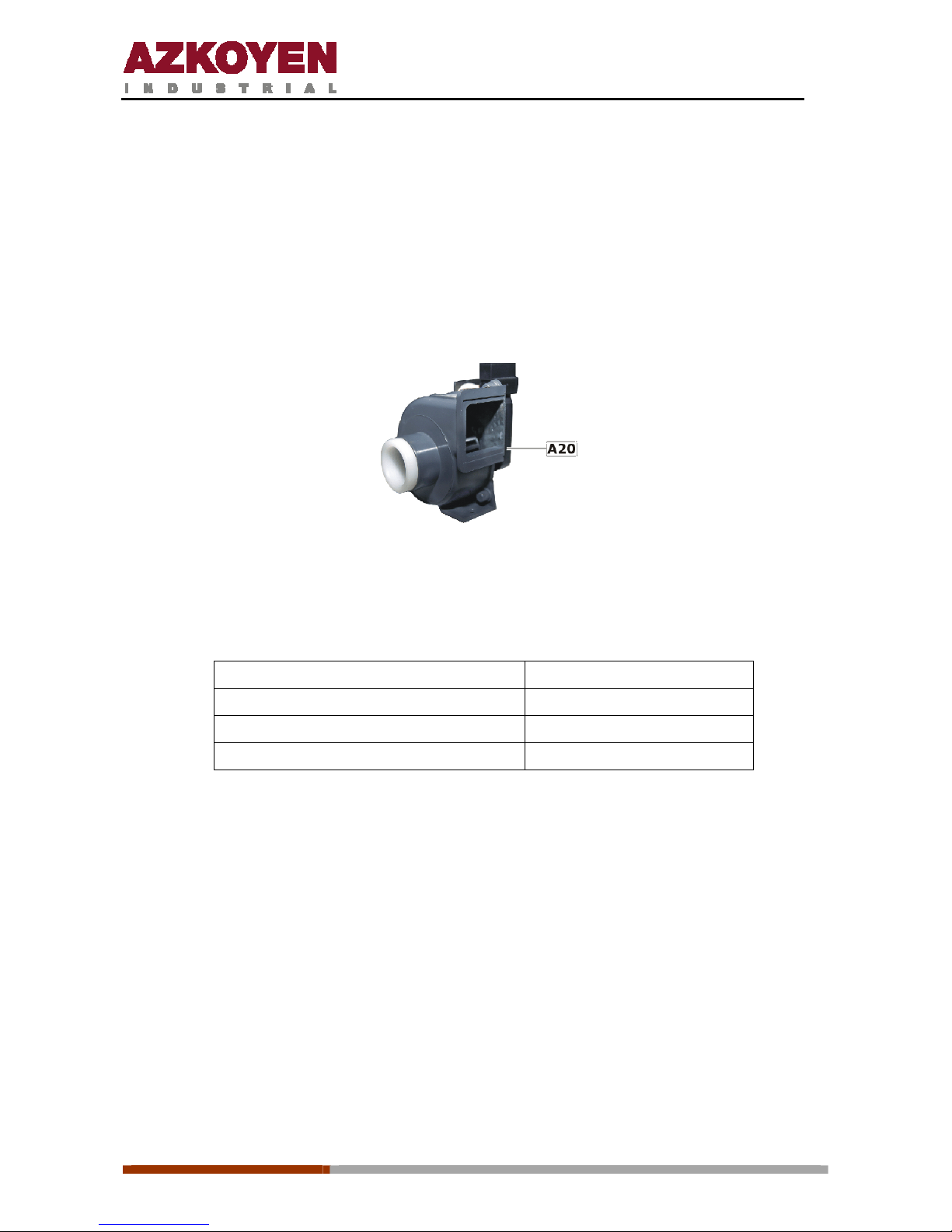
A20. Extractor
The steam and vapour that is generated by the beaters can reach the product containers and
if they become damp they form lumps in the powder. This consequently results in the
irregular extraction of the product. To avoid this, the extractor is used to remove the steam
and vapour
from the interior of the machine. It works on 230 Vac.
Extractor
A21. Transformer
Technical characteristics:
Primary 230 Vac
Secondary (blue-blue) 24 Vac
Secondary (black-black) 230 Vac
Power 96 w
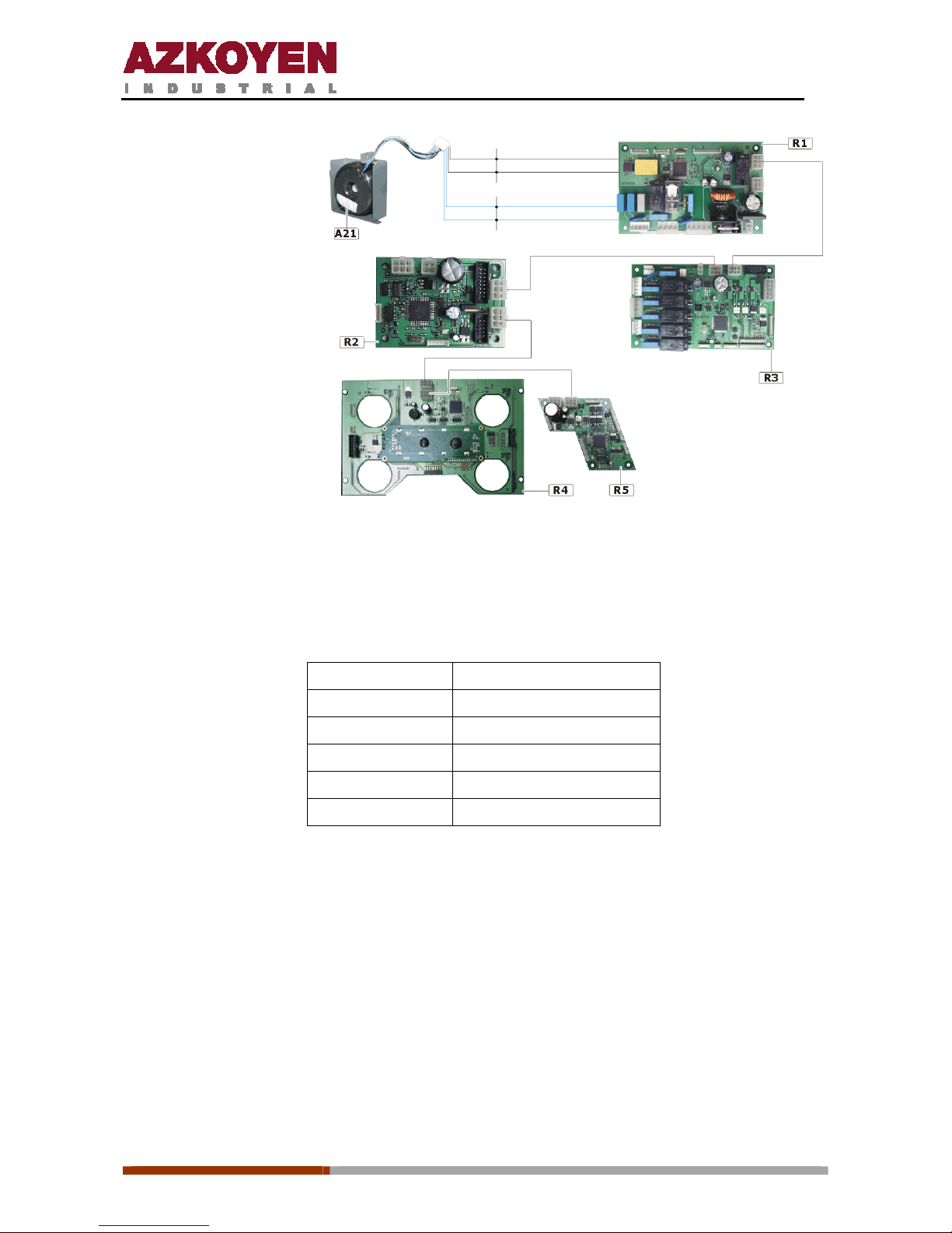
A22. Circuit boards
All the models in the City range have 5 circuit boards. The main module is the one that
provides the power supply to the other boards and takes the decisions for the correct working
of the machine. The other four boards control independently a determined number of elements
in the machine.
Page 25
1ª 10012 - E 02 - 2006
25
R1. Main module
R2. Payment module
R3. infusion module
R4. IDU module
R5. Cup module
The five boards are joined by one loom of 6 strands called a CAN bus. Two of these wires are
used for the transmission of 34 volts, another two for 8 volts and the remaining tw o are used
for the communication between boards. The colour and the function of each of the wires are
the following:
PIN 1. Orange Positive 34 volts
PIN 2. Grey Negative 34 volts
PIN 3. Red Positive 8 volts
PIN 4. Yellow Communication
PIN 5. Green Communication
PIN 6. Black Negative 8 volts
Black
Black
Blue
Blue
220Vac
24Vac
Page 26
1ª 10012 - E 02 - 2006
26
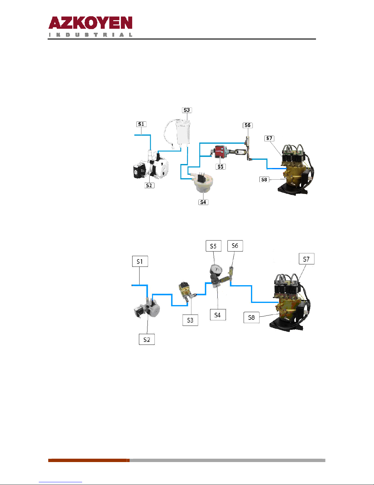
2.2. HYDRAULIC CIRCUIT OF THE ESPRESSO COFFEE
In the following diagram are represented all the elements of the machine that are needed to
control and make the water reach the infusion element or the instant beverage beaters.
S1.
Water inlet
S2.
Inlet electro valve
S3.
Cold water deposit
S4.
Flowmeter
S5.
Water pump
S6. Security
valve
S7. Electrovalves
S8.
Hot water boiler
2.3. HIDRAULIC CIRCUIT OF THE FRESH BREW MODEL
S1.
Water inlet
S2.
Inlet electro valve
S3. Flowmeter
S4. Pressure regulador
S5. Manometer
S6.
Security valve
S7. Electrovalves
S8.
Hot water boiler
This model will only work when connected to a mains water supply with a minimum pressure of
2 kg/cm². The machine comes with a pressure regulator of 2 kg/cm² and this is the pressure
that all the instant beverages and the teas are elaborated.
The pressure of the regulator can be modified by lifting the cover and turning it to the left or
right. Once regulated, push down the cover again. The manometer will show the pressure you
have set.
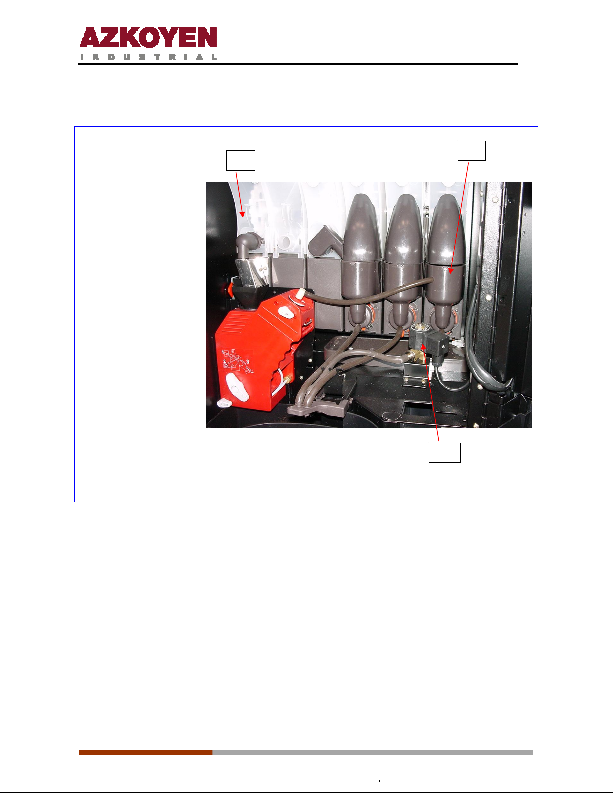
The tea is infused in the same way as in an infusion group for the espresso coffee machines.
The tea that has been infused goes to the instant tea beater, once the whole infusion process
is finished, and then an electro-valve is opened to let the infusion go to the cup. With this
Page 27
1ª 10012 - E 02 - 2006
27
method the infusion reaches the cup from a lesser height than the height of the outlet tube of
the infusion group, and thus avoiding bubbles in the tea.
T1. Container for green tea
(Infusion)
T2. Instant tea beater
T3. Electro-valve for tea
outlet
T1
T2
T3
Page 28
1ª 10012 - E 02 - 2006
28
3.
INSTALLATION AND SWITCHING ON
3.1. UNPACKING
The power supply of the machine requires a socket, or another system, that allows its disconnection.
The method used must guarantee the complete disconnection of both poles.
Elemental safety requirements:
a) Never touch any mechanisms with wet hands or feet.
b) Neve r co n n ec t or us e t he m ac hi ne b ar e fo ot .
c) Never pull on the flex to unplug the machine.
d) Never leave the machine exposed to the elements: sun, rain, snow, etc.
3.2. SWITCHING ON
Site the machine in its place and level it using the regulating feet.
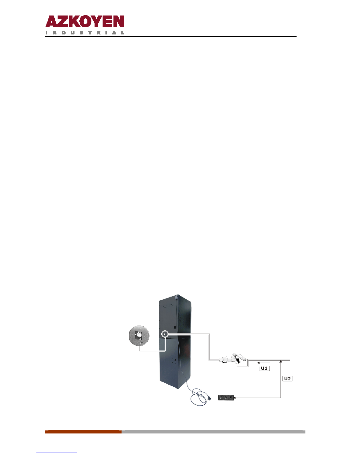
3.2.1. Water connection
The machine can be used connected to the mains or with an autonomous water deposit. To
connect the machine to the mains use a ¾” male connection. The mains supply must provide
drinking water at a minimum of 5 litres/minute and a pressure of between 0.5 and 10 kg/cm².
For the Fresh brew model, the minimum pressure is 2 kg/cm².
The connection hose for the mains is not supplied with the machine.
U1. Water
U2. Socket distance minimum
1 metre
Page 29
1ª 10012 - E 02 - 2006
29
Models LE and LI are prepared for connection to the mains water supply in the factory,
so no additional parts are necessary.
However, for models ME and MI, it is necessary to add: an electro valve for the
mains connection, a cold water deposit, a water level gauge and the connection hoses.
The reference
of this connection kit that includes this set is 41511891-0.
Depending on the quality of the water, hardness , chlorine, bleach, etc, the connection should be
complemented with a filter.
If the machine is fitted with a filter, the minimum water pressure should be 1 Kg/cm².
3.2.2. Electrical connection
The machine works with 230 Vac (50 Hz). The installation must have:
• An earthed socket
• A minimum power rating of 2500 w
• The installation site must have a breaker switch and a good earth connection
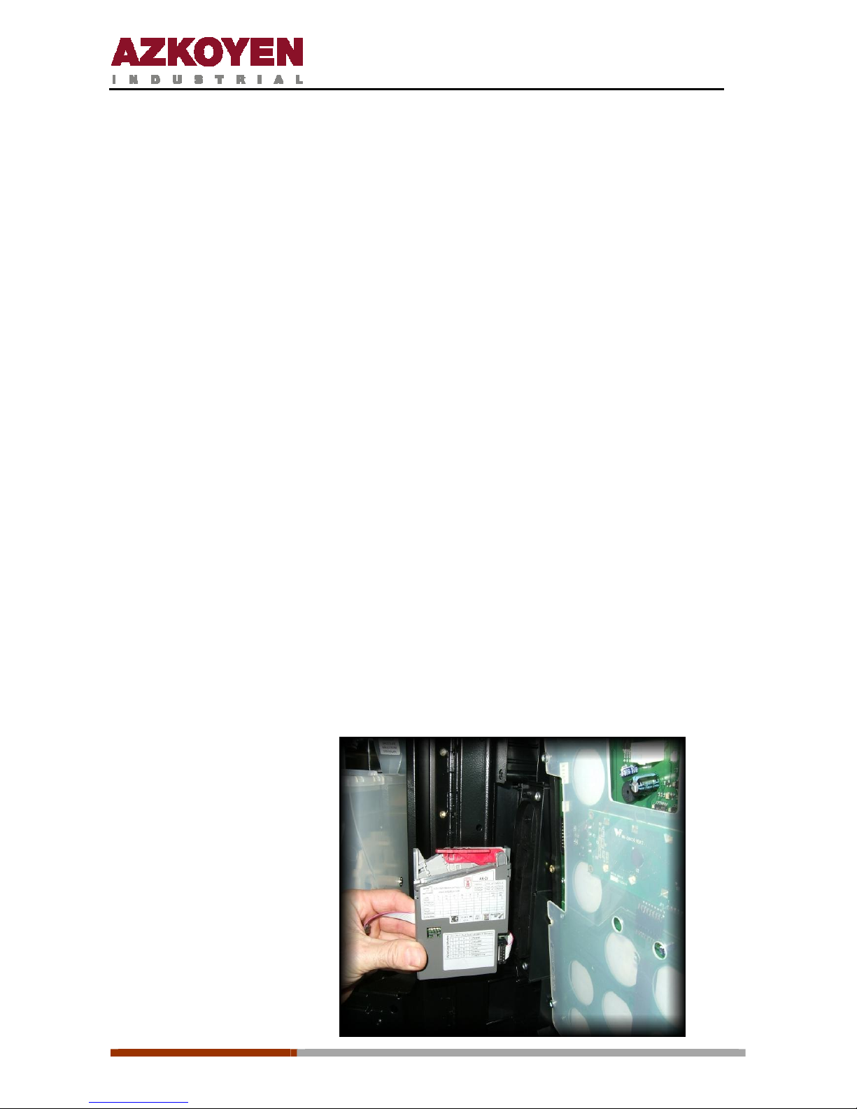
3.2.3. Connecting a Coin Validator (Ranges MI/ME)
The Tempo ME and Tempo MI models are factory prepared to install a coin validator, which can
be from Azkoyen or another manufacturer. The validator is not supplied with the machine.
The fitting of the validator is simple; it is clipped into the bracket.
The wiring loom for the validator is connected to JP8 on the MDP circuit board. The machine
only works with exact change.
Azkoyen A6 2i validator
Page 30
1ª 10012 - E 02 - 2006
30
3.2.4. Installing the coin changer with Executive or MDB protocol
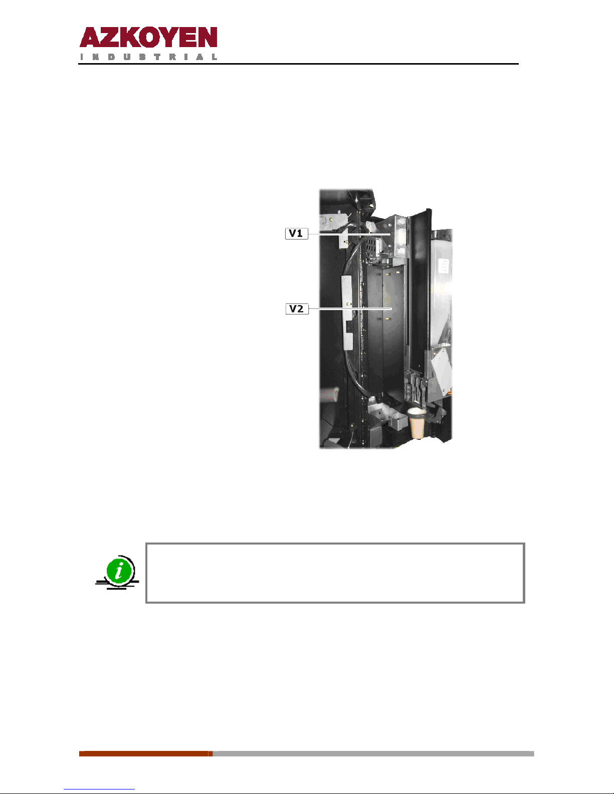
The Tempo LE and Tempo LI models admiten cualquier monedero con protocolo MDB o
Ejecutivo. Se fija mediante tres tornillos al soporte situado en la puerta. Este soporte es el
mismo para los dos modelos de monedero.
V1. Soporte conexiones
V2. Soporte monedero
3.2.5. Filling the product containers
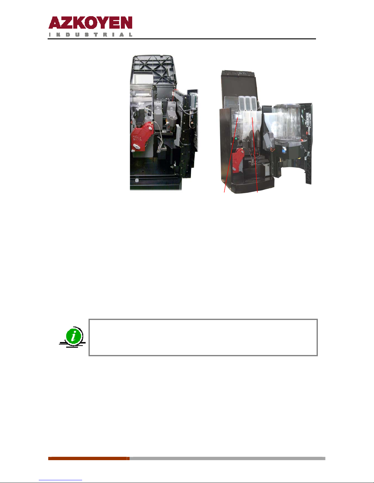
To put products in the containers, you should lift the cover of the machine. Otherwise it is
necessary to remove the container from the machine.
After filling the containers for instant beverages, it is advised to request a
service of each as the first time it is used, only a small quantity of product is
served
Page 31
1ª 10012 - E 02 - 2006
31
W1.
Coffee bean hopper
W2.
Instant powder hoppers
W1 W2
Now the machine can be switched on.
3.2.6. Filling the hot water boiler
On connecting the machine the hot water boiler fills automatically. In the espresso coffee
machines the following process occur:
- The cold water deposit fills up, if it is empty.
- The volumetric counter is tested and the boiler is filled wi th the EVs closed. When the
counter stops spinning, the boiler is full. Then the instant product EVs open to let out
the air in the lines and boiler.
If the counter does not spin for 10 seconds while filling the boiler the
machine will go out of order as there is no water. To reset this state, just
switch the machine off and then back on
Page 32
1ª 10012 - E 02 - 2006
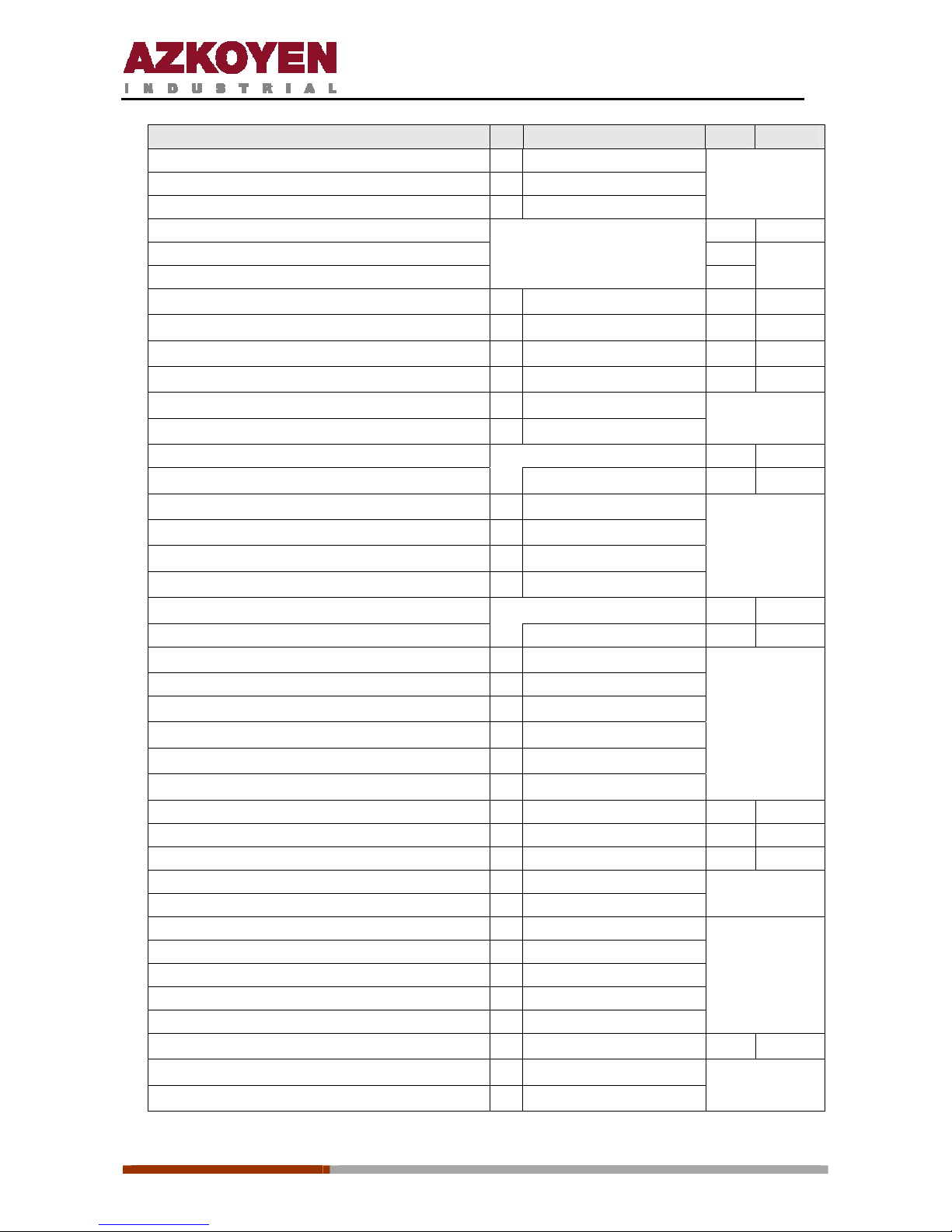
32
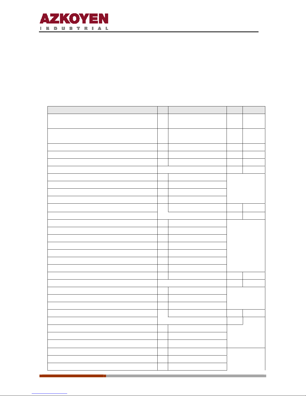
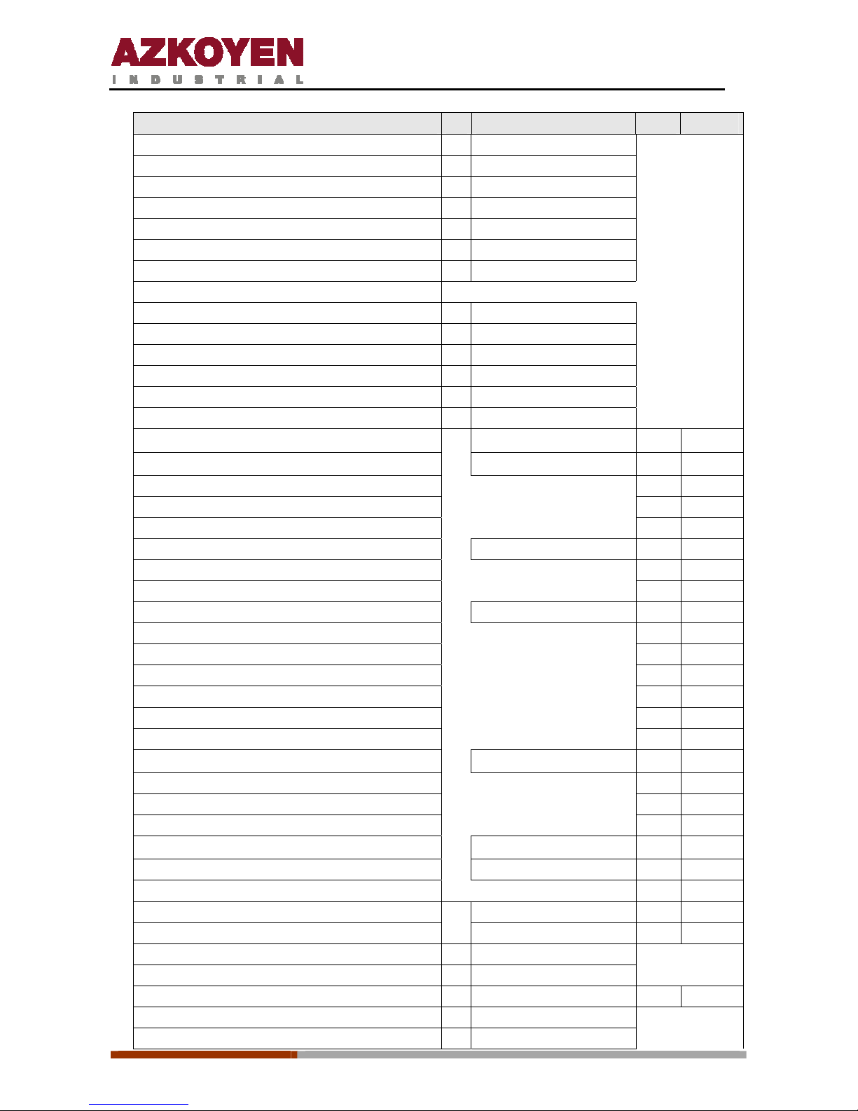
3.3. ERROR MESSAGES SHOWN ON THE DISPLAY
The description of the incident, the corresponding message that the display shows and the
codes that in each case will be transmitted when using VTM or EVADTS communication
protocols are:
Notes:
►: The machine is “out of order”
nn: number of the element that is faulty
Description Message on the Display VTM EVADTS
Fault in a CHANGER, type of fault 1
MDB: Sensor in tube defective
nn ERROR CHANGER 08 EAN1
Fault in a CHANGER, type of fault 2
MDB: Jam in tube
nn ERROR CHANGER 09 EAN2
Fault in a CHANGER, type of fault 3 nn ERROR CHANGER 0A EAN3
Fault in a CHANGER, type of fault 4 nn ERROR CHANGER 0B EAN4
Fault in a CHANGER, type of fault 5 nn ERROR CHANGER 0C EAN5
Fault in the validator 0D EAL
MDB: Validator disconnected 00 ERROR VALIDATOR
MDB: Error of checksum ROM 01 ERROR VALIDATOR
MDB: Jam of coins 02 ERROR VALIDATOR
VALID: Error in signal of coins 03 ERROR VALIDATOR
►
Fault in the module of recuperation ERROR RECUPERATION 0E EAB
Fault communication with the changer 11 EAR
MDB: Reply incorrect of the changer 02 ERROR CHANGER
MDB: Reply incorrect of the note reader 03 ERROR CHANGER
MDB: Reply incorrect of the card reader 04 ERROR CHANGER
MDB: Reply incorrect of the slave 05 ERROR CHANGER
MDB: Err. Product out of date (slave) 81 ERROR CHANGER
MDB: Err. Product sensor (slave) 82 ERROR CHANGER
MDB: Err. Keyboard in the slave 83 ERROR CHANGER
Fault button recuperation ERROR KEYBOARD 12 EGK
Fault keyboard selection 13 EGK
Number of button nn ERROR KEYBOAR D
Fault cup extractor EB ERROR CUP
Fault Infusion EC ERROR INFUSION
Fault keyboard selection, no keyboard ERROR KEYBOARD 14 EGK
Fault in the card reader 15
MDB: Error in the circuit board 00 ERROR CARD READER.
MDB: Circuit board not valid 01 ERROR CARD READER
MDB: Tamper Error (Fraud?) 02 ERROR CARD READER
MDB: Error defined by the manufacturer 03 ERROR CARD READER
MDB: Error in communications 04 ERROR CARD READER
MDB: Repair reader 05 ERROR CARD READER
Page 33
1ª 10012 - E 02 - 2006
33
Description Message on the Display VTM EVADTS
MDB: Not assigned 06 ERROR CARD READER
MDB: Error defined by the manufacturer 07 ERROR CARD READER
MDB: Error of the lector 08 ERROR CARD READER
MDB: Error in communications 09 ERROR CARD READER
MDB: Jam circuit board 0A ERROR CARD READER
MDB: Error defined by the manufacturer 0B ERROR CARD READER
MDB: Error refunding credit 0C ERROR CARD READER
Fault in the note reader
MDB: Motor defective 00 ERROR NOTE READER
MDB: Sensor defective 01 ERROR NOTE READER
MDB: Error checksum ROM 02 ERROR NOTE READER
MDB: Jam 03 ERROR NOTE REA DE R
MDB: Store / Stacker not present 04 ERROR NOTE READER
MDB: Lector deactivated 05 ERROR NOTE READER
►
Out of order because prices deprogrammed PRICE NOT PROGRAMMED 17 EAK
►
Out of order for all coins inhibited COINS INHIBIT. 18 EAC
Fault in extraction grid, type of ERROR 1 19 ELZ1
Fault in extraction grid, type of ERROR 2 1A ELZ2
Fault in extraction grid, type of ERROR 3 1B ELZ3
Fault detector product (fault type 1) FAULT IDETECT 1C
Fault in temperature 1D EJJ
Fault in product out of date 1E EJH
Fault detector product (fault type 2) FAULT IDETECT 1F
Switch on of the machine 20 OEZN
Swit ch off of the machine 21 OEZF
Activation of infra red reception 22 OEZI
Communication AZKOYEN protocol 23 OEZA
Communication EVADTS protocol 25 OEZE
Communication VTM under SMS 26 OEZS
►
Reset configuration Machine NOT CFG[F401] 30 ECZC
Reset program. Channels ,prices, etc 31 ECZP
Reset program. Messages 32 ECZM
Reset of accounting 33 ECZO
►
Error in EEPROM ERROR EEPROM ‘Module’ 37 ECO
Power low VOLTAGE LOW 38 ECA
Total memory erase order 39 ECN
Error clock EA ECL
Error temperature probe FAULT SENSOR TEMPER EB EJK
Temperature p robe open 01 OPEN SENSOR TEMP. AB
Temperature probe short circuited 02 OPEN SENSOR TEMP. CC
Error in system of door close DELIVERY DOOR OPEN 3D EGC
Gate closed 01 DELIVERY DOOR C
Gate open 02 DELIVERY DOOR A
Page 34
1ª 10012 - E 02 - 2006
34
Description Message on the Display VTM EVADTS
Gate undefined position, both micros closed 03 DEL. DOOR P.D. MC
Gate undefined position, both micros closed 04 DEL. DOOR P.D. MA
Detected manipulation of collection hatch 05 DEL. DOOR MANIP.
Product collection hatch open 41 EGC
Received module software by EVADTS 50
Received module software by MDB 51
►
Fault in system heater ERROR CALDERA 60 EDK
►
Error in the temperature probe 01 ERROR PROBE TEMP.
►
Error in the heating element 02 ERROR HEATING ELEMENT
►
Fault in water entry ERR. WATER LEVEL 61 EFL
►
Volume meter faulty 02 ERR: NO WATER
►
Error in the water level (no water) 03 NO MAINS WATER
Fault arm: not in out position 62 EBI1
►
Fault arm: not reached position ERROR ARM 63 EBI2
►
Arm not reached cup position 01 ERROR ARM P. CUP
►
Arm not reached liquid position 02 ERROR ARM P. LIQ.
►
Arm not reached sugar position 03 ERROR ARM P. SUGAR
►
Arm not reached stirrer position 04 ERROR ARM P. STIR.
►
Fault arm 3 faults without reset 64 EBI3
Fault system extract or of cups ERROR SYS. COPS 65 EBM
►
Error in the mfc of the cup hopper 01 ERROR CUP HOPPER
Cup hopper empty after 5 turns 02 NO CUPS
►
Error in the mfc of the extractor of cups 04 ERROR EXTRAC. CUPS
►
Cup arm turning 05 ARM HOP. TURNING
►
Cup extractor turning 06 CUP EXTR. H. TURNING
►
Cup hopper turning 07 HOPPER V. TURNING
Fault system extract or of st irre rs ERROR STIRRERS 66 EDF
Stirrer arm turning 01 ARM STIR. TURNING
Fault in the espresso infusion group ERROR GRP. ESPRESSO 67 EE
Error in the mfc of the doser 01 ERROR DOS.
Error in the positioner of the group 02 ERR. POS. GROUP
No coffee in grinder 03 NO GROUND COFFEE
No infusion gr oup 04 NO GROUP
Infusion time too long 05 LONG INF. TIME.
Retry of position of the group 06 RETRY. POS. GROUP
Retry of priming water pump in mach with deposit 07 RETRY PUMP PRIME
►
Fault in waste drawer ERROR IN WASTE 68 EDZ
►
Waste drawer full 00 WASTE DRAWER FULL
►
No waste drawer fitted 01 WASTE DRAWER NOT PRES.
Page 35

1ª 10012 - E 02 - 2006
35
3.4. Control points
Heating element
It is measured on the infusion board on the connector J12
Between pins 1 and 2 (black and brown) it will show 0 Vac when the heating element is
working. (Keeping in mind the 10 Amp fuse is correct)
Between pins 1 and 2 it will show 220 Vac when the heating element is not heating.
Infusion pump
It is measured on the infusion board on the connector J14
Between pins 1 and 4 it will show 200 Vac when the pump is working.
Water inlet electro-valve
It is measured on the infusion board on the connector J14
Between pins 2 and 4 it will show 200 Vac when the pump is working.
Motor of the infusion group
It is measured on the infusion board on the connector J15
Between pins 1 and 3 it will show 220 Vac when the group is working.
Dosage element
It is measured on the infusion board on the connector J15
Between pins 1 and 4 it will show 220 Vac when the dosage element is active.
Grinder
It is measured on the infusion board on the connector J15
Between pins 1 and 5 it will show 220 Vac when the grinder is working.
Transformer
It is measured on the PRI board on the connector JP1
Pins 1 and 2 = 220 Vac (black wires).
Pins 4 and 5 = 24 Vac (blue wires)
Infusion electro-valve
It is measured on the infusion board on the connector J9
Between pins 7 and 8 it will show 25 Vdc when the electro-valve is activated.
Page 36

1ª 10012 - E 02 - 2006
36
Volume counter
It is measured on the infusion board on the connector J10.
The pin 3 corresponds to +, the pin 4 to ground and the pin 2 to signal.
Wh en the counter spins, the reading will show 2.5 Vdc measuring between pins 2 and 4.
Water level buoy
It is measured on the infusion board on the connector J10.
Bet ween pins 1 and 4 it will show 0 Vdc when the deposit is contains water.
Bet ween pins 1 and 4 it will show 5 Vdc when the deposit is empty.
Micro-switch-switch for dosage element
It is measured on the infusion board on the connector J9.
Bet ween pins 1 and 6 it will show 5 Vdc when the dosage element is full.
Bet ween pins 1 and 6 it will show 0 Vdc when the dosage element is empty.
Micro-switch-switch for infusion group motor
It is measured on the infusion board on the connector J9.
Between pins 2 and 6 it will show 5 Vdc when the infusion group is in the coffee making
position.
Between pins 2 and 6 it will show 0 Vdc when the dosage element is in the loading
position.
Micro-switch-switch to detect infusion group presence
It is measured on the infusion board on the connector J9.
Bet ween pins 3 and 6 it will show 0 Vdc when the infusion group is fitted in the machine.
Between pins 3 an d 6 it will show 5 Vdc when th e infusion group h as been removed from
the machine.
Micro-switch for waste bucket
It is measured on the infusion board on the connector J11.
Bet ween pins 1 and 2 it will show 5 Vdc when the waste bucket is full.
Bet ween pins 1 and 2 it will show 0 Vdc when the waste bucket is not full.
Cup extractor motor
It is measured on the Cup Board on the connector J5.
Bet ween pins 9 and 11 it will show 0 Vdc when the motor is at rest.
Page 37

1ª 10012 - E 02 - 2006
37
Bet ween pins 9 and 11 it will show 25 Vdc when the motor is working.
Motor for turning the cup container
It is measured on the Cup Board on the connector J5.
Bet ween pins 7 and 10 it will show 30 Vdc when the motor is at rest.
Bet ween pins 7 and 10 it will show 0 Vdc when the motor is working.
Motor for the sugar extractor
It is measured on the Cup Board on the connector J7.
Bet ween pins 3 and 6 it will show 30 Vdc the motor is at rest.
Bet ween pins 3 and 6 it will show 0 Vdc when the motor is working.
Motor for the stirrer extractor
It is measured on the Cup Board on the connector J7.
Bet ween pins 3 and 5 it will show 30 Vdc the motor is at rest.
Bet ween pins 3 and 5 it will show 0 Vdc when the motor is working.
Photocell for detecting cup presence
It is measured on the Cup Board on the connector J5.
Bet ween pins 6 and 7 it will show 5 Vdc when there are cups between the photocells.
Bet ween pins 6 and 7 it will show 0 Vdc when there are no cups.
Micro-switch of the cup container lever
It is measured on the Cup Board on the connector J5.
Bet ween pins 3 and 7 it will show 5 Vdc when the lever is at rest.
Bet ween pins 3 and 7 it will show 0 Vdc when the lever closes the micro-switch.
Micro-switch for the cup extractor motor
It is measured on the Cup Board on the connector J5.
Bet ween pins 4 and 7 it will show 0 Vdc when the motor is at rest.
Bet ween pins 4 and 7 it will show 5 Vdc when the motor turns to extract a cup.
Micro-switch sugar arm
It is measured on the Cup Board on the connector J7.
Bet ween pins 2 and 3 it will show 5 Vdc when the arm is at rest.
Between pin s 2 an d 3 it w ill show 0 Vdc when th e arm moves t o deposit su gar in the cup,
it returns to 5 Vdc when it returns to its original position.
Page 38

1ª 10012 - E 02 - 2006
38
Temperature probe
It is measured on the infusion board on the connector J2. It measures the resistance
values (see the table for the PTC values).
4. CLEANING AND MAINTENANCE
Daily
Ô Liquid residue bucket. Empty the waste water and rinse with clean water.
Ô Solid waste bucket. Empty the coffee residues and rinse with clean water.
Ô Liquid collector tray. Clean with a water and dish washing liquid solution.
Ô Beaters. Carry out various auto-cleaning operations by pressing button “B” on the
programming handset.
Weekly
Ô Infusion group. Remove it from the machine and rinse it under a tap to remove
coffee particles. Before replacing the group, dry it with a cloth.
Ô Beaters. Remove the beaters, the outlet tubes and the chamber from the machine,
and clean everything with a water and dish washing liquid solution. If necessary,
only use a soft cloth to clean so as not to scratch their surfaces.
Ô Product collection cover. Clean it with a water and dish washing liquid solution.
Ô Cup support arm. Remove and clean it with a water and dish washing liquid
solution.
Three monthly
Ô Product hoppers. Remove them from the machine and empty them. Clean them
with a water and dish washing liquid solution. Dry them before replacing into the
machine. Clean the supports where the hoppers are fitted.
Ô Coffee bean hopper. Carry out the same as with the product hoppers.
Page 39
1ª 10012 - E 02 - 2006
39
Depending on the use of the machine
Ô Piston filter. Every 15,000 services, it is recommended to remove and clean it. If
necessary, it can be cleaned with a non metallic brush. If the holes are blocked, do
not introduce sharp objects into the holes to clean them. It is recommended to
replace the filter with a new one when is becomes blocked.
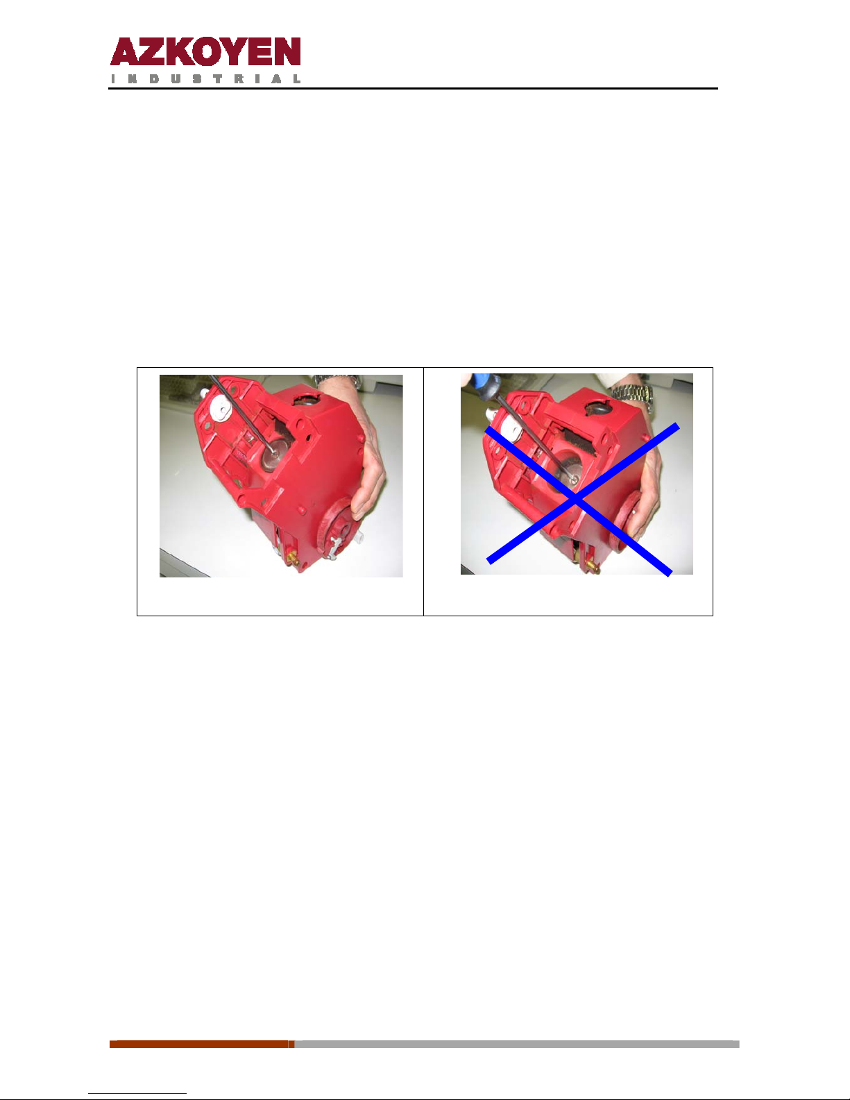
Ô Infusion group filter. Clean the infusion group filter at the same time as you clean
the piston filter. To remove the filter without damaging it, follow the guidelines
below: Move the group to the coffee cake extraction position. Hold the group and
the lever with one hand while loosening th e filter screw with th e other. On replacin g
the screw it is recommended to use Loctite 243 or a similar product to keep it tight.
OK
NO
Ô Piston seal. Substitute every 30,000 services
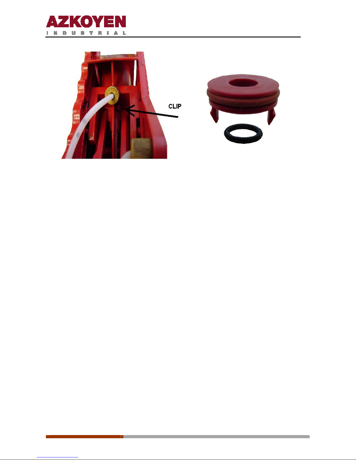
Ô Group seals. Substitute every 60,000 services. To get to these it is necessary to
remove the group filter. They are reachable by following the explanation below
.
1. Remove the filter holder and the group filter as shown above.
2. Press the clips (one on each side) indicated in the following photo until the part
is released at the gaskets.
3. After replacing the gaskets, fit the cover and gaskets back on the group.
Page 40
1ª 10012 - E 02 - 2006
40
Juntas
Maintenance tool
The maintenance tool is used in machines in the Tempo and City series to carry out various
advanced configuration and programming tasks.
The tool is micro-processor controlled and has a flash memory with a capacity to store at least
8 programme modules, 100 configurations or a combination of both.
The tool is connected directly to the machine to save or recuperate configurations. It can also
be connected to a PC to modify configurations or manage the module update programming
a
small non metallic brush.
Page 41

1ª 10012 - E 02 - 2006
41
5. WORKING CONDITIONS AND NORMS
The optimum working conditions of this equipment is achieved by fulfilling the following
requirements:
Temperatures:
Ô Storage: -25 to + 70ºC.
Ô Working: 0 to 50º C.
Ô Maximum relative humidity without condensation 85%
Norms that are met:
Ô The coffee machines meet the following EU directives: Directive 73/23/CEE electrical
safety and Directive 89/336/CEE electromagnetic compatibility.
Ô The mains connection cable has an earth wire as established in the electrical safety norm.
Ô The boiler has a temperature sensor that c ontrols the connection and disconnection of
the heating element automatically.
Ô The boiler has a temperature clixon that disconnects the heati ng el ement when it reaches
120º C.
Ô EN 60335-2-63:96
Ô EN 60 335-1(88) + A2(88) + A5(89) + A6(89) + A51(91) + A52(92) + A53(92) +
A54(92) + A55(93)
Ô EN 55014-1
Ô EN 61000-3-2
Ô EN 61000-3-3
Ô EN 55014-2:98 (EN 61000-4-2, 4-3, 4-4, 4-5, 4-6, 4-7, 4- 8 and 4-11)
Ô CE
For the correct working of all the elements, the maximum inclination the machine should
have on any of its axis should be ± 5º.
Page 42
1ª 10012 - E 02 - 2006
42
6. DIMENSIONS
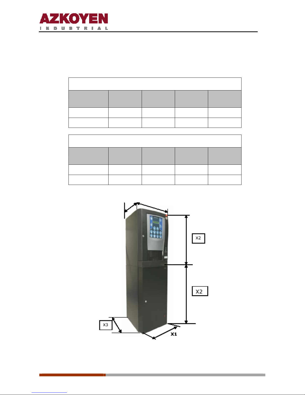
The measurements are in mm and the weights in Kg.
M A C H I N E
Tempo Width
X1
Height
X2
Depth
X3
Weight
ME/MI 600 1620 620 49/44
LE/LI 600 1830 620 60/55
C A B I N E T
Tempo Width
X1
Height
X2
Depth
X3
Weight
ME/MI 410 865 500 16/16
LE/LI 480 890 530 19/19
Page 43

1ª 10012 - E 02 - 2006
43
 Loading...