

Page 1
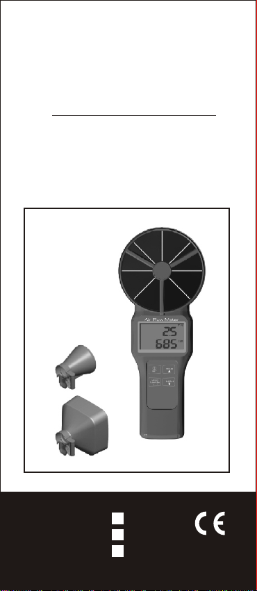
Operation Manual
10cm Vane
Wireless Air Flow Meter
with Airflow cone
Model:8903/8904/8906
Model:
89161
89171
89191
Page 2
Thank you for purchasing this wireless
INTRODUCTION
air flow meter. This meter is specially
designed for HVAC&R application that
combines those required measurements,
like Air Velocity, Air volume, Temp., RH,
WBT, DP, and CO2 in one handy meter.
Optional airflow cone helps in quick
volume measurement, just install the
compatible airflow cone, meter will
recognize the area for air volume
calculations automatically.
A hassle free way to take the value of
air volume .
Features :
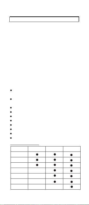
Wireless transfer with free App
available for both iOS & Android.
Available for air velocity, air volume,
temp., RH, WBT, DP, and CO2.
Big LCD digital display
Multi-points and Timed average
Metric& Imperial units selectable
Optional Round & Square airflow cone
Fast response &
Low battery indication
Blue back light for dark places use
Handheld size, easy to carry
Function Table
Air Velocity
Air volume
Air temp.
Humidity
Dew Point
Wet Bulb
CO2
Accurate reading
89161 8919189171
1
Page 3
MATERIAL SUPPLIED
This package contains:
The meter x 1
Battery x 4 (AAA size )
Operation manual x1
Hard carry case x1
Optional accessory:
Airflow cone set:
Round conex1 (dia.210mm)
Square conex1 (346x346mm)
CONTROLS AND INDICATORS
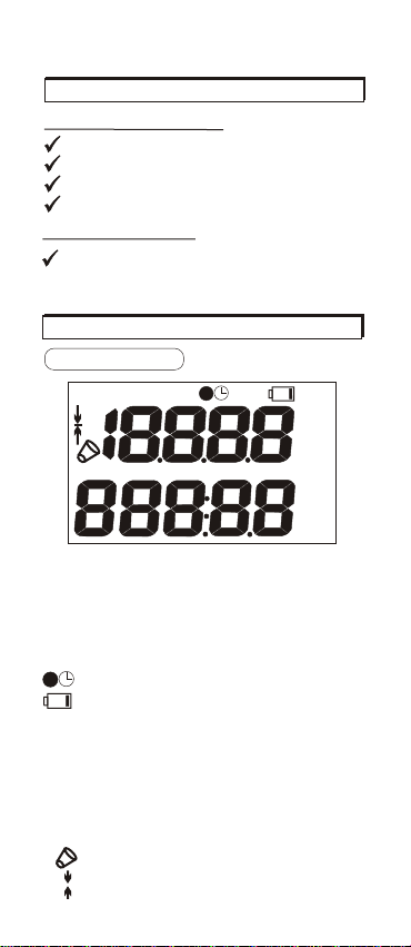
LCD DISPLAY
HOLD
inch
cm
Upper display: air velocity, RH, CO2 value.
(Depends on model) duration time in average.
Lower display: air volume, temp., WBT, DP
(Depends on model) value.
HOLD
MAXMIN:maximum & minimum reading
AVG: multi-points & timed average
: battery low voltage indicator
ppm
m/s,fpm: air velocity unit
%RH : relative humidity unit
OO
OO
: temperature unit
F
C
CMM,CFM: air volume unit
WBT, DP : wet bulb, dew point temp.
2
2
cm
inch
: area dimension unit
: air flow cone indicator
: vain icon in this meter
MIN
2
2
MAX
AVG
m/s
fpm
ppm
%RH
OO
C
CMM
CFM
WBT
DP
: freezes the current reading.
:CO2 unit
2
OO
F
Page 4
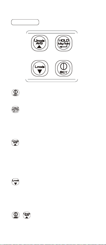
KEY PAD
-Power button
-Long press to enter or exit setup
mode.
-Freeze current reading on LCD
-Long press to review MIN and MAX
-In average mode, press to record
data or start timed recording.
-In setup mode, press to enter data
settings.
-Switch for upper display.
-Long press to enter average mode.
-In average mode, press to select
option of average mode, press again
to return to normal mode.
-In setup mode, press to select
category or increase value.
-Switch for lower display.
-In average mode, press to view
recorded and average reading of
all parameters.
-In setup mode, press to select
category or decrease value.
+ -Disable auto power off.
3
Page 5
MEASUREMENT
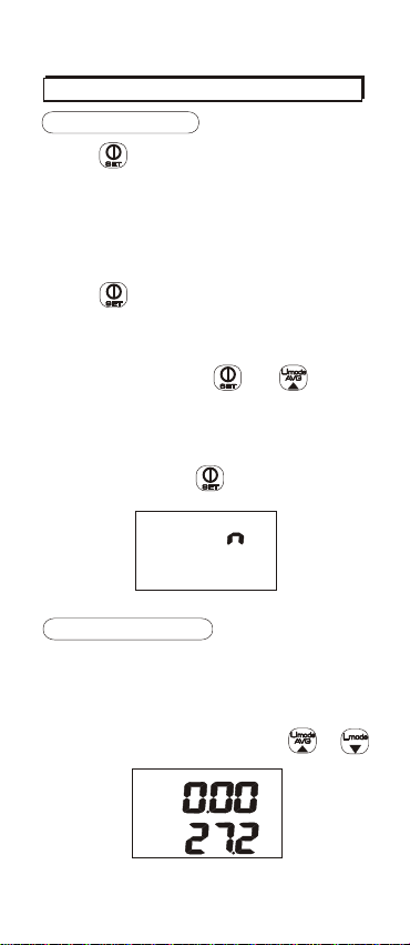
POWER ON/OFF
Press to turn on the meter. The
screen shows full display with blue
backlight on and enter normal mode.
(Model 89161/89171).
For model 89191,it proceeds 30
seconds warm up after turned on the
meter, then it enter normal mode.
Press again in any mode to turn
off the meter.
The meter is preset auto sleep in 20
minutes of inactivity. To disable this
function, hold down and for 2
seconds to turn on the meter while it is
off. It shows “n” on the LCD (see Fig.A)
and goes into normal mode(or 30 sec.
warm up for model 89191) and won’t
turn off itself until is pressed or out
of voltage.
Fig.A
SWITCH DISPLAY
When the meter is turned on, it shows
the current readings of air velocity on
the upper display and air temp. on the
lower(see Fig.B). To switch display of
other measurements, press or .
m/s
OO
C
Fig.B
4
Page 6
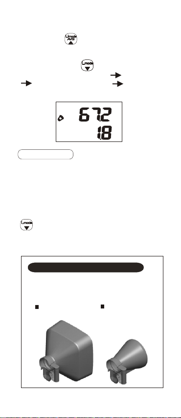
Short press , the upper display will
cycle among air velocity, RH, and
CO2 (89191 only).
And short press , the lower display
cycles among air temp. air volume
WBT(wet bulb temp) DP(dew
point temp)(Fig.C).
%RH
CMM
Fig.C
AIR VOLUME
To measure air volume, it is necessary
to get the outlet dimensions. Go to
Setup mode and input the AREA value
first before taking measurement. (See
page 9 , P2.0)
After AREA setting is completed, press
to switch the display to air volume
and the measured air volume will be
displayed on the lower LCD.
Measure with airflow cones
Two optional airflow cones are
available for using with this
anemometer and are sold as a set.
Square
346x346mm
Round
dia. 210mm
5
Page 7
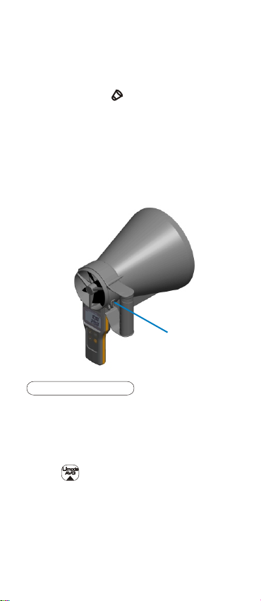
To measure air volume with use of an
airflow cone. Just plug on the cone and
the meter will automatically recognize
it and shows a on the display(Fig.C).
Then the meter will calculate the air
volume by the default dimensions
despite of any AREA value is input.
Note:
Be sure the airflow cone is well mounted
and locked tight. (See pic.1)
pic.1
Lock
RH(89171/89191 only)
The capacitive humidity sensor is built
in the center of the vane to measure air
flow relative humidity and is used for
calculating dew point and wet bulb
temperatures.
Press to switch to RH display. It
shows measured RH readings on the
upper display. And it is also possible to
display with RH offset. Go to Setup
mode (see page 9, P3.0) and input
offset value, then the displayed readings
will be the measured data with offset.
6
Page 8
CO2 (89191 only)
Model 89191 features additional CO2
measurement for HVAC application.
The NDIR CO2 sensor is built in the rear
side of the meter. Press to switch
to CO2 display and the current reading
will show on the upper LCD.
For places in high altitude, the pressure
compensation needs to be considered
in order to get accurate CO2 readings.
Go to Setup mode P4.0 and input the
pressure value according to your
location before taking measurements.
DATA HOLD
In normal mode, press and the
current readings are fixed on the LCD
with HOLD icon on the top and won’t
change until a second press on .
MIN/MAX
In normal mode, long press for 3
seconds and it displays the minimum
readings of all parameters since power
on with MIN icon on the top. Long press
this button again, it shows the maximum
readings with MAX on the top. (Fig.D)
Long press again and it returns to the
normal mode.
While reviewing the minimum and
maximum data, press and
and it switches to display MIN and MAX
readings of other parameters.
MAX
MAX
m/s
m/s
OO
OO
C
C
Fig.D
7
Page 9
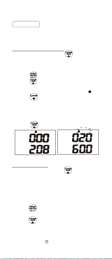
AVERAGE
This meter calculates multi-points
average and timed average of all
parameters.
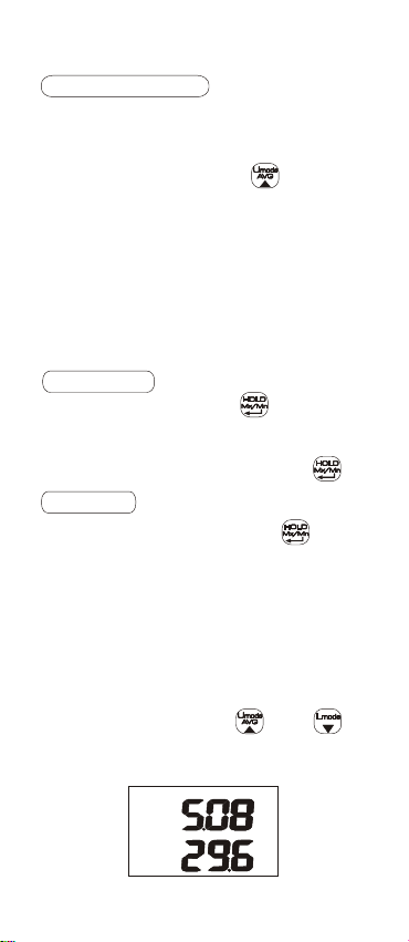
Multi-points average
In normal mode, press for 2 seconds
to enter multi-point average mode.(See
Fig.E, the upper display shows the record
number and the lower is the measured reading)
- Press to record readings.
- Press to see the multi-point average
once all data is recorded. It shows the
average readings with flashing” “.
AVGAVG
- Press to view the average reading
of each parameter.
(See Fig.F, the upper display means total
20 recorded data; and the lower display is
the average reading of RH.)
- Press to return to normal mode.
m/sAVG m/sAVG m/sAVG m/sAVG
AVG
AVG
%RH
%RH
Fig.E
Fig.F
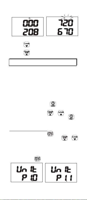
Timed average
In normal mode, press for 2 seconds
and it goes into multi-point average.
Press it again to enter timed average
mode. (See Fig.G, the upper display shows
the duration time in second, the maximum
time is 19999 seconds, and the lower is the
measured reading)
- Press to start recording, the upper
display starts the counting clock.
- Press to stop and calculate the
timed average. It shows the duration
seconds on the upper display and the
average readings at the lower display
with flashing” “. (See Fig.H)
AVG
AVG
8
Page 10
AVGAVGAVGAVG
AVGAVG
ppmp pm
OOCOO
C
Fig.G
Fig.H
- Press to view average reading of
other parameters.
- Press to return to normal mode.
SETUP
The setup mode is for those related
parameters setting that can ensure
more accurate measurements.
It includes:
P1.0: Unit selection
P2.0: AREA size
P3.0: RH offset
P4.0: Pressure input (model 89191 only)
In normal mode, press for 2 seconds
to enter SETUP mode. It starts with P1.0
unit selection. Press or to select
among P1.0 to P4.0. Long press
again to return to normal mode.
P1.0: Unit selection
In P1.0 (Fig.I), press to enter units
selection (Fig.J). Then press or
to switch from Metric to Imperial unit.
The units include air velocity(m/s, fpm),
temp.(C, F), air volume(cmm,cfm), and
area size(cm ,inch ). After finishing the
setting, press to return to P1.0.
2 2
2
2
cm
cm
m/s
OO
OO
C
C
CMM
CMM
Fig.I
Fig.J
9
Page 11
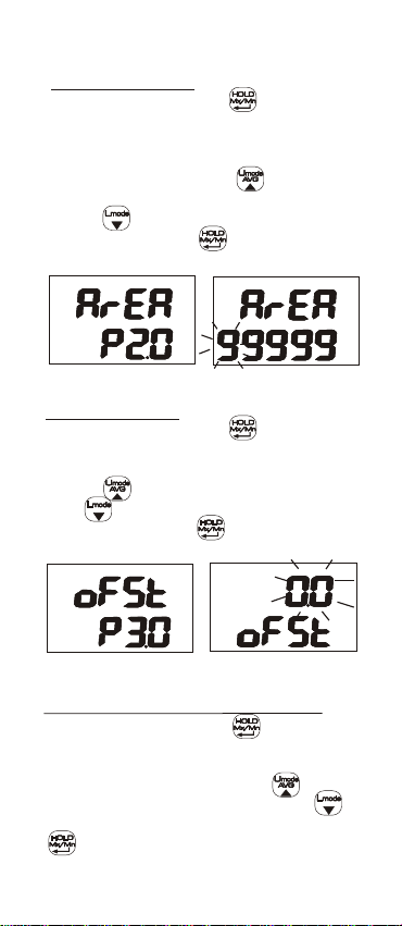
P2.0: AREA Size
In P2.0(Fig.K), press to enter AREA
size setting. It shows “99999” on the
lower display with the first digit flashing.
(Fig.L) The flashing digit means it is
ready to adjust. Press to change the
number and it will cycle from 0 to 9.
Press to move to next digit. After
completed, press again to return to
P2.0.
2
cm2cm
Fig.K
Fig.L
P3.0: RH offset
In P3.0(Fig.M), press to enter RH
offset setting. It shows blinking 0.0 RH
reading on the upper display(Fig.N).
Press to increase the offset value
and to decrease it. When finished
the setting, press again to return
to P3.0.
%RH%RH
Fig.M
Fig.N
P4.0:Pressure input (89191 only)
In P4.0 (Fig.O), press to enter
pressure input. It shows default 1013
hpa on the display with blinking value
at the upper (Fig.P). Press to
increase the pressure value and
to decrease it. Once finished, press
again to return to P3.0.
10
Page 12
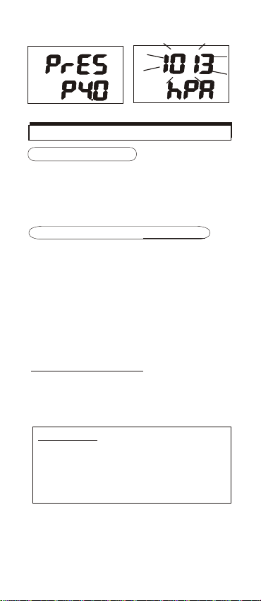
Fig.O
Fig.P
CALIBRATION
RH CALIBRATION
The humidity calibration of this meter
requires specific fixture and cannot be
done by end users. Please contact the
dealer for calibration service.
CO2 CALIBRATION(89191 only)
The meter is calibrated at standard
400ppm CO concentration in factory.
It’s suggested to do manual calibration
regularly to maintain good accuracy.
Note:
When the accuracy becomes a concern
after a long time use, return to dealers
for standard calibration.
400ppm calibration
400ppm calibration is suggested to be
done in outdoor fresh air that is well
ventilated and in sunny weather.
CAUTION:
Do not calibrate the meter in the air
with unknown CO concentration.
Otherwise, it will be calibrated as
default and leads to
inaccurate measurements.
2
2
400ppm
Place the meter in the calibration site
and follow the below procedure to
complete the 400ppm calibration.
11
Page 13
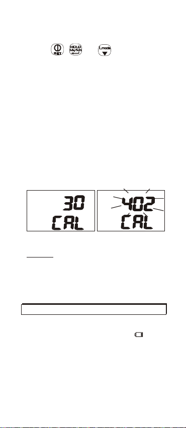
1. While the meter is turned off, hold
down , and simultaneously
to enter CO2 calibration mode. It runs
30 seconds countdown with CAL at
lower display(Fig.T), and then starts
400ppm calibration.
2. During calibration, a CO2 reading in
the range of 380 to 420ppm will be
flashing on the upper display.(Fig.U)
3. Wait for 10 minutes until the reading
stops flashing, the 400ppm calibration
is completed and it returns to normal
mode automatically. .
To abort the calibration, turn off the
meter at any time.
ppm
Fig.T
Fig.U
NOTE:
Be sure the batteries are with full
voltage during the calibration to
prevent from interruption and fail
in the calibration.
LOW-BATTERY
When the battery voltage falls below the
measurement required range, shows
on the LCD. Replace with fresh batteries
to ensure accurate measurements.
12
Page 14
Nice Flow App installation
Smart device system requirement
iOS version above iOS
Android version above 5.0
Please always remember to enable
the wireless function on smart device
before using this App.
App function
Main Page
Preference display
User can choose which parameters to be
displayed at the main page.
Default setting is to display all parameters,
press “ star ” button next to the parameter to
remove the one you don’t want to see at the
main page, and press again to add it back.
Main Page
Press to return to the main page and
view the current measuring values of
different meters.
(Maximum display 5 meters at one time)
Files
Press to check the history data of
Avg-Min-Max data.
About
Information of privacy and version.
Return
Return to previous page.
13
Page 15

Avg-Min-Max by App
This App is able to calculates
multi-points average / timed average,
and display together with Minimum /
Maximum values of all parameters after
starts the recording process.
User can determine when to start and
when to stop the calculation, or when
to take the measurements under
Point Avg. Mode by App.
The data will be saved automatically
after stop recording, it can be output in
csv format for further analyze.
Timed average
- Select one device at one time on main
page, you will see the detail of current
measurements of the specific meter.
- Press “Time Avg.” to enter the Timed average mode.
- Press “Start” to start recording, the
upper right corner display the time
duration of recording.
- Press “Stop” to stop recording, the
data will be saved automatically.
-Check the recording detail at “Files”
Multi-points average
- Select one device at one time on main
page, you will see the detail of current
measurements of the specific meter.
- Press “Point Avg.” to enter the Point
Average mode.
- Press “Start” to record, the upper
right corner display the total record
point
- Press “Stop” to stop recording, the
data will be saved automatically.
-Check the recording detail at “Files”
14
Page 16

Data Review & Output by App
Search Recorded Data
- Press “File” to enter the search page
- Enter serial number or file name at the
upper blank area, press “icon ” to
search.
- The search result will be listed, click
“File Name” to see the detail.
Edit File Name
- Select the file and you will see the
“Rename” option appear.
- Click “Rename”, click edit, enter file
name.
- Press Save to save the file name.
Send in CSV format
- Select the file and you will see the
“CSV” option appear
- You can select multiple files to send
them in CSV format for further analyze.
Delete File
- Select the file and you will see the
“delete” option appear.
- Click “delete” to delete the file, the
delete file will not be able to resume,
please be sure before press click.
15
Page 17

Setting by App
User is able to do the setting by App.
- Select one meter on main page
- Press “ SET ” on upper left corner for
general setting list as below:
Device Name
- Press Device Name to start.
- Enter maximum 6 characters for
device name setting.
- Press ok to confirm.
Unit Selection
- Press Unit to start.
- Select Metric or Imperial.
- Press ok to confirm.
RH off set(89171/89191 only)
- Press RH off set to start.
- Enter the number between 0~12 for
RH off set setting.
- Press ok to confirm.
Pressure input (89191 only)
- Press Absolute pressure to start.
- Enter number between 700~1990 for
pressure compensation.
- Press ok to confirm.
Outlet Area input
User can also input the outlet area via
App, please follow below steps:
- Ensure airflow cone is not installed
- Press the meter you would like to input
outlet area on main page
- Press “Volume Flow” for outlet area
input, 3 options available:
*Area: Enter the calculated outlet area
*Diameter: If the outlet is in round
shape, enter the diameter
*LxW: Enter the Length and Width of
the outlet area
16
Page 18

TROUBLESHOOTING
1. Power on but no display
1) Make sure the time of pressing
key is more than 200mS.
2) Check the batteries are in good
contact with correct polarity.
3) Replace new batteries and try again.
2. Display disappeared
Check whether the low battery
indicator shows before display
disappears, if yes, replace with new
batteries.
3. Error code and solution
1)Air Temp.
E02: Temp. is under low range limit.
Put the meter in room temp for
30 minutes. If E02 still shows,
send to the dealer for repair.
E03: Temp. is over high range limit.
Put the meter in room temp for
30 minutes. If E03 still shows,
send to the dealer for repair.
E31: temperature measuring AD
damaged. Send to the dealer
for repair.
2) RH
E04: temperature error caused the
RH error. Check the temp.
error solution.
E11: RH calibration error.
Try recalibration or send for
repair if it still can’t work.
E33: RH measurement circuit error.
Send to the dealer for repair.
17
Page 19

3) DP and WBT
E04: Temp. or RH error.
Check temp. or RH error
solution.
4) Air velocity
E03: Velocity is over high range limit.
Try in range measurement. If
it still shows in range velocity,
recalibrate it send for repair.
5) Air volume
E03: Reading exceeds display limit.
Check if the outlet area setting
is correct.
E04: Air velocity error.
Try recalibration or send for
repair if it still can’t work.
6)CO2
E03: Temp. is over high range limit.
Put the meter in room temp.
for 10 minutes and if E03 still
shows, recalibrate it or send
for repair.
E01/E33: Voltage too low or CO2
module error.
Check if battery low icon showed
on the LCD, if yes, replace with
new batteries.
Try recalibration, or send for
repair if it still can’t work.
7) Others
E32: Memory IC error.
Turn off the meter and turn it
on again. If E32 still shows,
send to the dealer for repair.
18
Page 20

TROUBLESHOOTING FOR APP
1. App no display
1) Make sure meter is power on with
display.
2) Turn off other BLE device.
3) Close the app and switch it on again.
FCC Radiation Exposure Statement
This equipment complies with FCC RF
radiation exposure limits set forth for an
uncontrolled environment. This
equipment should be installed and
operated with a minimum distance of 0.5
centimeters between the radiator and
your body.
This transmitter must not be co-located
or operating in conjunction with any
other antenna or transmitter.
The antennas used for this transmitter
must be installed to provide a separation
distance of at least 0.5 cm from all
persons and must not be co-located or
operating in conjunction with any other
antenna or transmitter.
19
Page 21
SPECIFICATION
Measuring r ange
Air velocity 0.20~30.00m/s
Air volume
Temperature
Relative Humidity
DP(Dew point temp.)
WBT(Wet bulb temp.)
CO2
Resolution
Accuracy
Air velocity +/-(1.5% of reading +0.3m/s) for under 20m/s
Temperature
Relative Humidity
CO2
CO2 Warm-up time
Vane / Meter siz e (mm)
Air flow cone size(mm)
Round Dia. 210
Square 346x346
Operating condition
(avoid condensation)
Storage c ondition
Power supply
Standard package
Optional accessory Air flow cone set ( w /soft carry case ),
89161 89191
0.1m/s, 0.1(0~9999.9) or 1(10000~99999), 0.1 C/ F, 0.1%RH
Meter, manual ,AAA bat.,Hard carry case
Extension set
Certification
This device complies with Part 15 of the
FCC Rules. Operation is subject to the
following two conditions:
(1) This device may not cause harmful
interference, and
(2) This device must accept any
interference received, including
interference that may cause
undesired operation.
89171
3
0 to 99,999 m /m
o o
-20.0~60.0 C (-5~140 F)
N/A
N/A
N/A
N/A N/A
+/-(3% of reading +0.3m/s) for above 20m/s
N/A
N/A
N/A
Dia. 100, 269(L)x106(W)x51(H)
-10~ 50 C, <90%RH(avoid condensation)
0.1%~99.9%RH
o
-5.0~59.9 C
o
-20.0~59.9 C
0~9999 ppm,
(5001~9999 ppm out o f scale range)
o o
o
+0.6 C
o
+3%RH(a t 25 C, 10~90%RH) ; +5%RH( oth ers )
+30ppm+5% of rdg.(0~5000ppm)
N/A
N/A
0 to 50 °C, <80%RH
o
AAA x 4pcs
30 seconds
20
Page 22

WARRANTY
The meter is warranted to be free from
defects in material and workmanship
for a period of one year from the date
of purchase. This warranty covers
normal operation and does not cover
battery, misuse, abuse, alteration,
tampering, neglect, improper maintenance
or damage resulting from leaking batteries.
Proof of purchase is required for
warranty repairs. Warranty is void if the
meter has been opened .
RETURN AUTHORIZATION
Authorization must be obtained from the
supplier before returning items for any
reason. When requiring a RA (Return
Authorization) , please include data
regarding the defective reason, the
meters are returned along with good
packing to prevent any damage in
shipment and insured against possible
damage or loss.
21
Page 23

Accuracy, the Zenith of
Measuring / Testing Instruments !
Anemometer
Data logger
Datalogging printer
Gas Leak Detector
CO meter
CO2 meter
Hygrometer/Psychrometer
RTD probe Thermometer
K.J.T.R.S.E. type Thermometer
Heat Index Meter / WBGT Meter
Infrared Thermometer
Manometer
Tachometer
Sound Level Meter
pH Meter
Conductivity Meter
T.D.S. Meter
D.O. Meter
ORP Meter
More products available !
2018.09 v.01
 Loading...