

Page 1
AZEL
TECHNOLOGIES
UNIVERSAL SINGLE ZONE SWITCHING RELAY
INSTALLATION AND OPERATING INSTRUCTIONS
SP-81
0513-1
APPLICATION
The SP-81 universal single zone switching relay is
operated by low voltage thermostats or any other low
voltage controllers having a SPST switching action. The
SP-81 provides intermediate switching to permit up to two
separate line voltage loads such as circulators.
FEATURES
. Modern Design with Indicator lights (LEDs) on the front
panel which provide functional status
. Fuse protection
. Power surge protection
. High Quality Electronics Circuit Board which simplifies
wiring and control Operation
. High Capacity Field Replaceable Transformer
. Easy-Connect Terminals/Screwless Terminals for
Thermostat Connections
. Common 24VAC transformer terminal provides
compatibility with electronic thermostat
. Compatible with Most Digital/Mechanical Thermostats
. 100% Factory Tested
. RoHS compliance & Environmental Friendly - Do Not
Contain hazardous substances (heavy metals such as
lead, mercury, cadmium etc).
. Extended 3 year warranty
MOUNTING
Mount the SP-81 to a suitable surface. Slotted keyholes and
standard holes are provided for mounting purposes.
ROUGH-IN WIRING
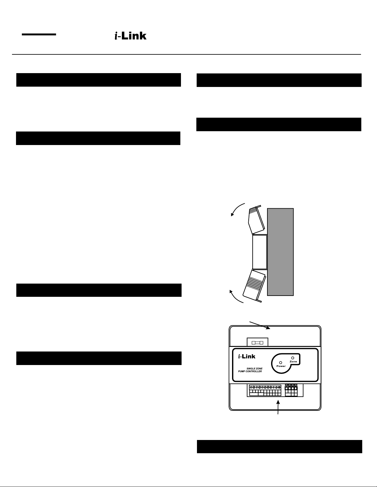
Loosen the screw on the top and bottom of the enclosure and
remove the wiring cover by swinging it away from the
base(grey color) with the edge of the cover as pivot(see
Figure 1). Note: The top fuse cover can be removed for
mounting holes or changing the fuse.
The base has standard 7/8” (22mm) knockouts which accept
common wiring hardware and conduit fittings. Before
removing the knockouts, check the wiring diagrams and use
the chamber with common voltages.
Fuse Cover
Side view
SPECIFICATIONS
Model: SP-81 Single Zone Switching Relay
Power Supply: 120 VAC, 50/60Hz
Dimensions: 6 3/8”(W) x 6 5/8”(H) x 2 3/4”(D)
Electrical Switch Rating: 10 A 1/3 HP @ 120VAC
Thermostat Anticipator Setting: 0.18 A
Enclosure: Flame Retardant Plastic 94V0
Shipping Weight: 2 lbs.
CAUTION!
1. Improper installation and operation of this control could result
damage to the equipment and possibly even personal injury. All
wiring must comply with national and local electrical codes,
ordinances, and regulations. Use Copper wires only. 120 VAC
wiring must have a minimum temperature rating of 75 C. 12-22
gauge wire is recommended for thermostat and 24 VAC source
connections. 12-18 gauge wire is recommended for 120 VAC
connections. Never connect the load terminals to a load that
takes more current than the amount listed for the relay in the
electrical ratings.
2. To prevent electrical shock hazard, disconnect power supply
before installing.
3. Azel Technologies is not liable for an special, incidental, indirect
or consequential damages resulting from the use of its products.
4. This literature is provided for informational purposes only.
Wiring Cover
Figure 1
The Front Upper cover can be removed to
Med. Temp
T T
24 VAC
OUT IN
Heat
Cool
access the mounting holes or the fuse.
FUSE
SP-81
3 4 3
N N L L
4 6 5 6
NC
C
NO
C
NO NC
Vac
R C R W
24
JUMPER
120 VAC
The Front Lower cover can be
L N NO C NC NO C NC S1 S1 S2 S2 S3 S3
removed to access the wiring
120 Vac Relay 1 Relay 2 Sensor Inputs
L N
L.E.D. SYSTEM STATUS INDICATION LIGHTS
RED light indicates thermostat calling for heat.
GREEN light indicates presence of power supply.
Page 2
OPERATION
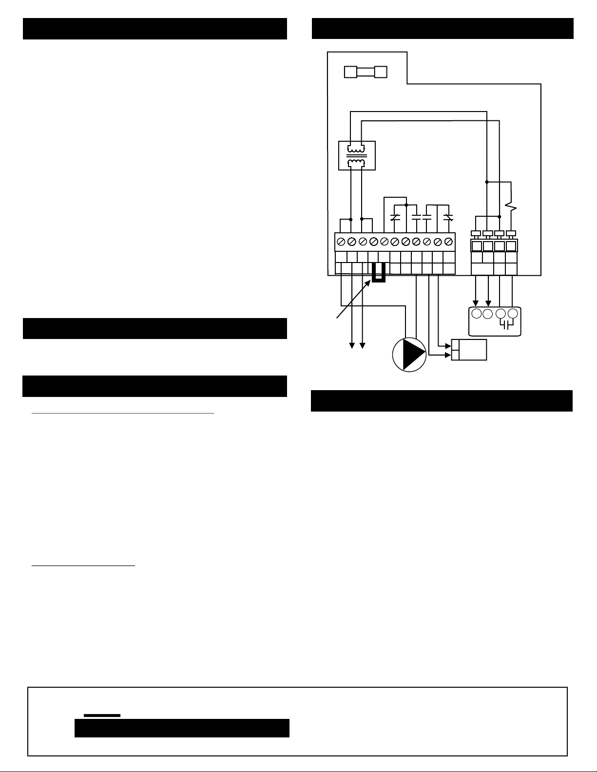
TYPICAL WIRING DIAGRAM
When the thermostats(or any other low voltage controller
having SPST switching action) calls for heat, the relay is
energized to turn on both circulator(or line voltage load)
and boiler controller.
Thermostat calling for heat (R/T and W/T circuit is
made):
! Terminals 3/C & 4/NO are closed to turn on the
circulator(jumper must be installed between L/JUMPER
and 3/JUMPER)
! Terminals 3/C & 4/NC are open
! Terminals 5/C & 6/NO are closed to turn on the
boiler/burner control
! Terminals 5/C & 6/NC are open
Thermostat not calling for heat (R/T and W/T circuit is
not made):
! Terminals 3/C & 4/NO are open(circulator is turned off)
! Terminals 3/C & 4/NC are closed
! Terminals 5/C & 6/NO are open(boiler/burner control is
turned off)
! Terminals 5/C & 6/NC are closed
Factory
JUMPER PLACEMENT
Installed
Jumper
Factory installed jumper between L(JUMPER) and 3(JUMPER)
allows power to be switched on terminal 4NC and 4NO
TERMINAL DESCRIPTION
Line Voltage Terminals(from left to right)
N 120 VAC Neutral Terminal Output to Circulator
N 120 VAC Neutral Terminal Input
L 120 VAC Hot Terminal Input
L/JUMPER See JUMPER PLACEMENT section
3/JUMPER See JUMPER PLACEMENT section
4/NC Normally Closed Terminal
3/C Common Terminal for 4/NC & 4/NO(connected to
3/JUMPER)
4/NO Normally Open Terminal (120 VAC Hot Output to
Circulator with jumper installed)
Note: Both N terminals are interconnected
Both L terminals are interconnected
Low Voltage Terminals
6/NO Normally Open Terminal
5/C Common Terminal for 6/NO & 6/NC
6/NC Normally Closed Terminal
R/24VAC 24VAC Hot Terminal Output
C/24VAC 24VAC Common Terminal Output
R/T 24VAC Thermostat Hot Terminal
R/W Thermostat Switching Terminal
Note: 24VAC outputs(R & C Terminals) can be used to power
electronic thermostat(eg. Azel Technologies D-135E)
FUSE
24 Vac
120 Vac
3 4 3
N N L L
JUMPER
120 VAC
(COM)
120 VAC
(HOT)
4 6 5 6
NC
C
NO
N
L
Circulator
R C R W
C
NO NC
Power to
thermostat
T
T
24
Vac
NC: Normally Closed
NO: Normally Open
C: Common
Relay
Coil
Med. Temp
T T
24 VAC
2 32 34 5
Boiler/
Burner
Control
Thermostat
(eg. Azel Tech, D-135E)
Note: Press down the white
OUT IN
lever to insert wire into the
screwless terminal blocks
TROUBLE SHOOTING
When 120VAC is supplied to SP-81, the green indicator
light should be on. When the thermostat calls for heat, both
the red indicator light and the circulator should be on.
! If the green light is on and the circulator cannot be
turned on by the thermostat(red light is off), remove
the thermostat and put a piece of wire across the
thermostat terminals (R/T and W/T) to simulate
thermostat calling for heat. If the circulator can be turned
on along with the red light, then check the thermostat for
functionality.
! If both green light and red light are on and the
circulator cannot be turned on, re-tighten the screws
for the jumper on terminal L and 3 and try again.
! If red light is on all the time, check the thermostat for
functionality. Remove the thermostat from the SP-81
and put a piece of wire across R/T and W/T terminal to
simulate the thermostat calling for heat. If everything
works properly, then the thermostat is faulty.
! If the green light is off, check the fuse and the
presence of 120VAC power supply . If the fuse is fine
and there is no power output on R C (24VAC) terminals,
the transformer (model: 0511F) needs to be replaced.
AZEL
TECHNOLOGIES INC.
www.azeltec.com
Please visit our website for other products
P.O. Box 53138
10 Royal Orchard Blvd.
Thornhill, Ontario, Canada L3T 7R9
Ph: 905-223-5567 Fax: 905-223-3778
Email: [email protected]
 Loading...