

Azbil VY5302A0031, VY5302A0011, VY5302A0023, VY5302A0041, VY5302A0042 Specifications & Instructions
...Page 1
ACTIVAL™
/
91
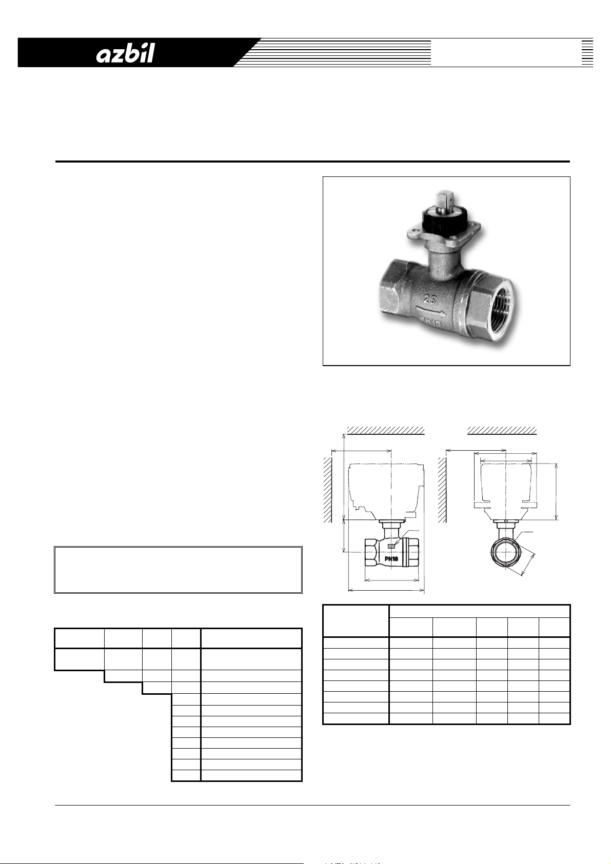
Two-way Ball Valve with Threaded-end Connection
General
ACTIVAL™ Model VY5302A is a two-way ball valve with
threaded-end connection (ISO 7-1: 1994). It proportionally
controls chilled/hot water for HVAC applications.
Model VY5302A has bronze valve body, stainless-steel ball
and stem, and the components exposed to process fluid are
made of other corrosion resistant materials.
Cv value and size variation of Model VY5302A are best
suited to HVAC control.
Model VY5302A is used in combination with the actuator
Model MY53X0A. Regarding the detailed information on the
actuator, refer to:
Specifications/Instructions of ACTIVAL Model MY53X0A
HVAC: Heating, ventilation, and air conditioning
ISO: International Organization for Standardization
AB-6594
Specifications/Instructions
Features
● Compact and lightweight:
Valve can be installed in a restricted space such as
inside of a compact AHU.
● Bronze valve body applicable to PN16.
● Easy assembly with Model MY53X0A actuator using no
tool, and no adjustment required.
● Equal percentage flow characteristic.
AHU: Air handling unit
IMPORTANT:
To control ACTIVAL with a third-party controller,
please consult with our sales person.
Model Numbers
Base model
number
VY53 Two-way valve with
Material
0 Bronze
2A00 Fixed
11 DN15 (1/2”) / 2.5 in Cv
12 DN15 (1/2”) / 4 in Cv
22 DN20 (3/4”) / 6.3 in Cv
23 DN25 (1”) / 10 in Cv
31 DN32 (11/4”) / 16 in Cv
41 DN40 (11/2”) / 25 in Cv
42 DN40 (11/2”) / 40 in Cv
51 DN50 (2”) / 40 in Cv
Size
Cv
Description
threaded-end connection
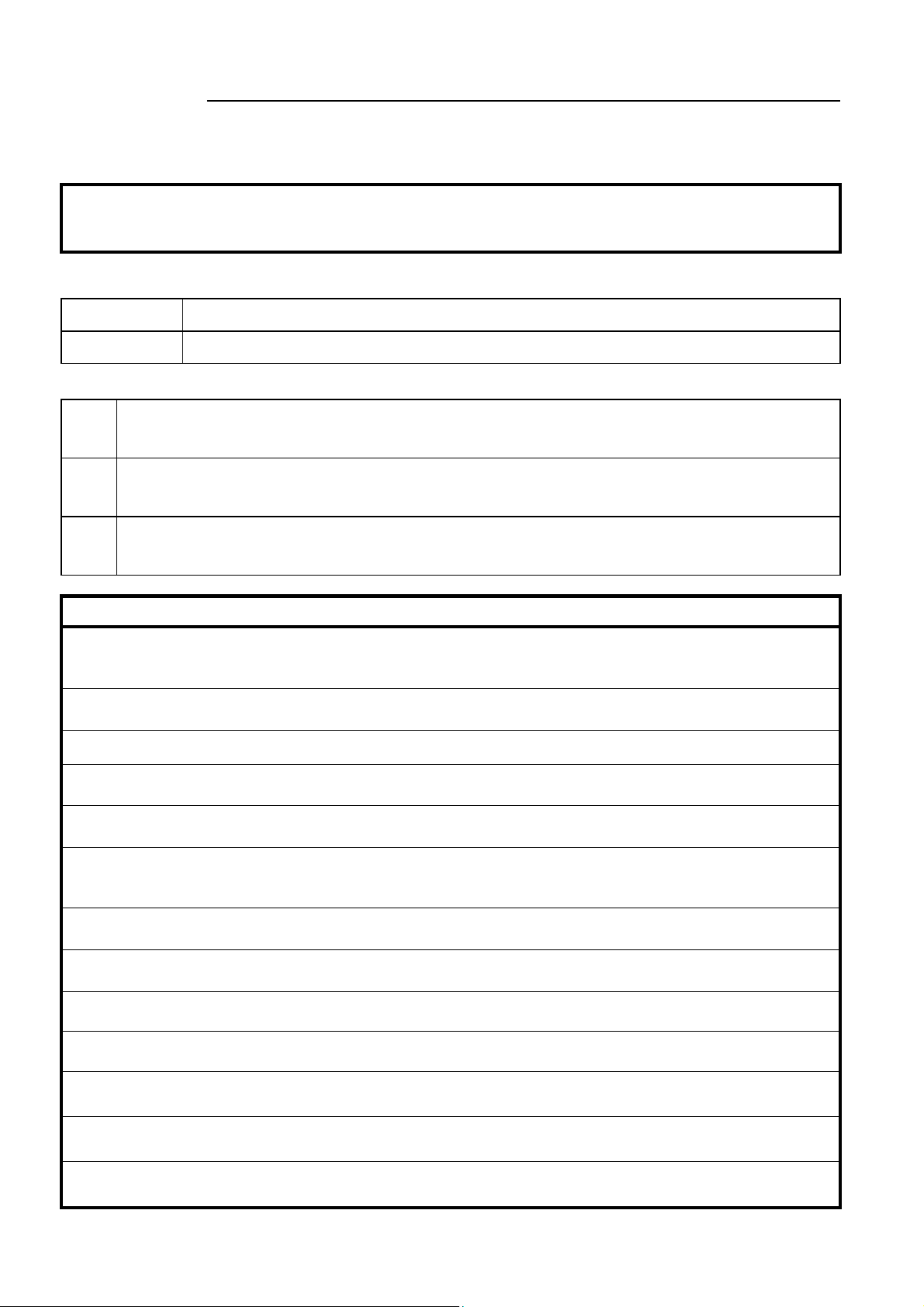
Dimensions and Maintenance Clearance
min.120
min.400
H
(MY53)
DN
Model number
VY5302A0011 DN15 Rc 1/2 63 47.5 27
VY5302A0012 DN15 Rc 1/2 63 47.5 27
VY5302A0022 DN20 Rc 3/4 72 50 33
VY5302A0023 DN25 Rc 1 85 53.5 41
VY5302A0031 DN32 Rc 11/4 98.5 68.5 50
VY5302A0041 DN40 Rc 11/2 108.5 72 56
VY5302A0042 DN40 Rc 11/2 108.5 72 56
VY5302A0051 DN50 Rc 2 109 73 69
Note:
* Rc: Internal tapered pipe thread complying with ISO 7-1: 1994.
Figure 1. Dimensions and maintenance clearance (mm)
L
120
Valve size Rc*
min.120
Dimensions
100
80
Rc
E
L
(mm) H(mm)E(mm)
1
Page 2
AB-6594
Safety Instructions
Please read instructions carefully and use the product as specified in this manual. Be sure to keep this manual near by for ready
reference.
Usage Restrictions
This product is targeted for general air conditioning. Do not use this product in a situation where human life may be affected. If
this product is used in a clean room or a place where reliability or control accuracy is particularly required, please contact our
sales representative. Azbil Corporation will not bear any responsibility for the results produced by the operators.
Warnings and Cautions
WARNING
CAUTION
Signs
Alerts users possible hazardous conditions caused by erroneous operation or erroneous use. The symbol inside I
indicates the specific type of danger.
(For example, the sign on the left warns of the risk of electric shock.)
Notifies users that specific actions are prohibited to prevent possible danger. The symbol inside Q graphically
indicates the prohibited action.
(For example, the sign on the left notifies that disassembly is prohibited.)
Instructs users to carry out a specific obligatory action to prevent possible danger. The symbol inside d graphically
indicates the actual action to be carried out.
(For example, the sign on the left indicates general instructions.)
Install and use the product under the operating conditions requirement (temperature, humidity, power, vibration,
shock, mounting direction, atmospheric condition, etc.) as listed in the specifications.
Failure to do so might cause fire or device failure.
Use the product within its lifespan and avoid instrumentations that keep the product to operate excessively.
Continued use beyond the lifespan might cause fire or device failure.
Installation and wiring must be performed by qualified personnel in accordance with all applicable safety standards.
Install the product in the proper position as specified in this manual.
Excessively tight connection to a pipe or improper installation position might damage the product.
After installation, make sure no fluid leaks from the valve-pipe connections.
Incorrect installation might cause fluid leakage.
Install the product so that no foreign objects remains inside the pipes. Be sure to provide a strainer (suitable for the
process fluid) on the inflow side of the piping. Flush the piping to remove the foreign objects after installation.
Foreign objects inside the piping might damage the product.
Do not excessively screw the valve into a pipe.
Doing so might damage or deform the inside of the valve causing leakage and malfunction.
Do not allow process fluid to freeze.
Doing so might damage the valve body causing leakage.
Do not install the product nearby a steam coil or a hot-water coil.
High temperature radiation might cause malfunction of the actuator assembled with the valve.
Do not use the product in an atmosphere corrosive to the product, its actuator, and their components.
Doing so might damage the product.
Do not disassemble the product.
Doing so might cause device failure.
Do not carelessly touch the product when being used to control hot water.
The product temperature goes high, and you might get burned.
Dispose of the product as industrial waste in accordance with your local regulations.
Do not reuse all or part of this product.
Alerts users that improper handling may cause death or serious injury.
Alerts users that improper handling may cause minor injury or material loss.
CAUTION
2
Page 3
AB-6594
r
Specifications
Item Specification
Type Two-way ball valve with threaded-end connection (internal), proportional control
Applicable actuator to be combined Model MY53X0A
Pressure rating PN16 (Max. working pressure: 1.6 MPa)
Valve size, Cv, close-off rating
Materials Body Cast bronze (equivalent to: - CuAn5An5Pb5-C (DIN EN1982) for global standard
End connection Internal threaded-end (equivalent to ISO 7-1: 1994)
Applicable fluid Chilled/hot water, brine (ethylene glycol solutions, 50 wt.% max.)
Allowable fluid temperature 0 C to 100 C (non-freezing)
Flow characteristic Equal percentage
Rangeability 100 : 1
Seat leakage in fully closed position 0.01 % of rated Cv value (0.0006 Cv or less for DN15 models)
Mounting position On vertical / horizontal pipe
Weight
(Actuator in combination is NOT
included.)
DIN: Deutsche Industrie Normen
EPDM: Ethylene-propylene-diene copolymer
JIS: Japanese Industrial Standards
PTFE: Polythetrafluoroethylene
Model numbe
VY5302A0011 DN15 (1/2”) 2.5 1.0 MPa
VY5302A0012 DN15 (1/2”) 4 1.0 MPa
VY5302A0022 DN20 (3/4”) 6.3 1.0 MPa
VY5302A0023 DN25 (1”) 10 1.0 MPa
VY5302A0031 DN32 (11/4”) 16 0.5 MPa
VY5302A0041 DN40 (11/2”) 25 0.5 MPa
VY5302A0042 DN40 (11/2”) 40 0.5 MPa
VY5302A0051 DN50 (2”) 40 0.5 MPa
Ball Cast stainless steel
Stem Stainless steel
Seat ring PTFE
O-ring EPDM
VY5302A0011 0.4 kg
VY5302A0012 0.4 kg
VY5302A0022 0.6 kg
VY5302A0023 0.8 kg
VY5302A0031 1.2 kg
VY5302A0041 1.5 kg
VY5302A0042 1.5 kg
VY5302A0051 1.8 kg
Nominal size Cv Close-off rating
- CAC406 (JIS) for Japanese standard)
3
Page 4

AB-6594
Parts Identification and Materials
Valve size: DN15 to DN40 Valve size: DN50
5. Stem
5. Stem
6. O-rings
1. Body
6. O-rings
2. Seat retainer
1. Body
2. Cap
4. Ball
4. Ball
No. Part name Material No. Part name Material
1
Body
2
Cap
3
Seat ring PTFE
4
Ball Stainless steel
5
Stem Stainless steel
6
O-ring EPDM
Figure 2. Parts identification and materials: DN15 to DN40 valve Figure 3. Parts identification and materials: DN50 valve
3. Seat rings
Cast bronze
(equivalent to: - CuAn5An5Pb5-C (DIN EN1982)
- CAC406 (JIS))
Cast bronze
(equivalent to CuAn5An5Pb5-C (DIN EN1982))
3. Seat rings
1
2
3
4
5
6
3. Seat rings
Body
Seat
retainer
Seat ring PTFE
Ball Stainless steel
Stem Stainless steel
O-ring EPDM
Cast bronze
(equivalent to: - CuAn5An5Pb5-C (DIN EN1982)
- CAC406 (JIS))
Copper alloy
3. Seat rings
Flow Characteristic
Cv (%)
100
75
50
25
0
25 50 75 100
Valve position (%)
Figure 4. Flow characteristic diagram
4
Page 5

AB-6594
Installation
CAUTION
Installation and wiring must be performed by qualified personnel in accordance with all applicable safety standards.
Install the product in the proper position as specified in this manual.
Excessively tight connection to a pipe or improper installation position might damage the product.
After installation, make sure no fluid leaks from the valve-pipe connections.
Incorrect installation might cause fluid leakage.
Install the product so that no foreign objects remains inside the pipes. Be sure to provide a strainer (suitable for the
process fluid) on the inflow side of the piping. Flush the piping to remove the foreign objects after installation.
Foreign objects inside the piping might damage the product.
● To remove foreign substances inside the pipes, install a strainer on the inflow side of each valve. In case that the strainers
cannot be installed on the inflow side of each valve, install it on the pipe diverting sections (sections diverting from main
piping system to sub piping system).
● Install the valve so that the flow direction of process fluid agrees with the arrow indicated on the valve body.
Installation location
CAUTION
Do not install the product nearby a steam coil or a hot-water coil.
High temperature radiation might cause malfunction of the actuator assembled with the valve.
Do not use the product in an atmosphere corrosive to the product, its actuator, and their components.
Doing so might damage the product.
● Install the valve assembled with the actuator in a position allowing easy access for maintenance and inspection. Fig. 1
shows the minimum clearance for maintenance and inspection. When installing the valve and actuator in a ceiling space,
provide an access panel within the 50 cm radius of the valve and actuator. And, place a drain pan under the valve.
● Do not mount the valve on a pipe where water hammer occurs, or where solid objects including slug may accumulate.
Mounting position
The valve (assembled with the actuator) can be mounted in any position ranging from upright to sideways (90 tilted). The valve
should be installed with its actuator vertically positioned above the valve body. However, the valve must be installed always in
upright position outdoors.
Correct examples Incorrect examples
Figure 5. Mounting positions of the valve
5
Page 6

AB-6594
Piping
● Install a bypass pipe and gate valves on the inflow, outflow, and bypass sides. Also, install a strainer (with 40 or more
meshes) on the inflow side.
● When installing the valve to pipes, do not allow any object, such as chips, to get inside a pipe or valve. Valve cannot fully
closes, or the valve seat may get damaged causing fluid leakage, due to an foreign object jammed inside the valve.
● When piping, do not apply too much sealing material, such as solidifying liquid and tape, to the pipe connection sections so
that these materials flow into the valve. Valve cannot fully closes, or the valve seat may get damaged causing fluid leakage,
due to the sealing material jammed inside the valve.
● When connecting the valve to pipes, hold the valve body (where a pipe is screwed) with a tool such as a wrench, and screw
the pipe into the valve. (See Fig. 6.) Do not apply excessive torque to the pipe. Refer to the table in Fig. 6 for the
recommended torque.
Incorrect
holding position
Torque
Valve size (DN) 15 20 25 32 40 50
Max. torque
Recommended torque to screw into the pipe
(Nm)
40 60 100 120 150 200
Correct holding
position
Figure 6. Valve connection to a pipe
● Before activating the valve and actuator, flush the pipes (with the valve and actuator installed) at the maximum flow rate to
remove all the foreign substances. Fully open (in 100 % position) the valve to flush. (Factory preset position: 100 %)
Heat insulation
Do not apply heat insulation to the joint surface. Correctly apply heat insulation to the valve as shown in Fig. 7.
Joint
surface
Joint surface
Heat insulation
material
Heat insulation
material
Correct application Incorrect application
Figure 7. Heat insulation
Factory preset position
ACTIVAL is set in fully open (100 %) position before shipment.
6
Page 7

AB-6594
/
r
A
Assembling the valve Model VY5302A with the actuator Model MY53X0A
IMPORTANT:
The actuator can be horizontally rotated every 90 degrees to fit into the valve mounting position (4 mounting
positions). Make sure the positions of the actuator and the valve as follows, referring to Fig. 8:
- Actuator: Indicator/manual lever points at 100 (fully open position).
- Valve: An arrow on the top of the stem points at 100 (fully open position).
(Align the hole on the side of the stem with the tip at the joint surface as ‘a’ in Fig. 8 shows.)
Set the ACTIVAL (actuator and valve) in 100 % position when changing the mounting position.
If the valve in 0 % position is assembled with the actuator in 100 % position, the actuator put torque on the
closed valve, and the gear of the actuator gets damaged.
If the valve and the actuator are assembled despite their positions unmatched, they might operate reversely
and become unable to control the process fluid.
Indicator
manual leve
ctuator
Model MY53X0A
Lock lever
Lever release button
Stem
a
Valve
Model VY5302A
Figure 8. Mounting the actuator onto the valve
Mounting procedure
1) Manually turn the indicator/manual lever of the actuator
to “100” with the lever release button pressed.
Turn.
Figure 9. Indicator/manual lever at 100 % (fully open) position
2) Move the lock lever to right-end to unlock.
Unlock.
Figure 10. Unlocking the lock lever
Press.
3) Confirm that the arrow on the top of the valve stem points
at “100”. A hole on the side of the stem faces the same
direction at which the tip of the valve joint surface (with
the actuator) points when the valve position is fully open.
(See ‘a’ in Fig. 8.)
Stem
Tip
Joint surface
Figure 11. Valve stem pointing at 100 % (fully open) position
4) Assemble Model MY53X0A actuator with the valve.
Engage 4 pins of the actuator with the mating holes on
the valve joint surface.
5) Move the lock lever to left-end to lock. Locked position is
indicated with the groove as shown in Fig. 12.
Locked position indication
Lock.
Figure 12. Locking the lock lever
7
Page 8

AB-6594
A
Inspection and Troubleshooting
CAUTION
The product temperature goes high, and you might get burned.
● Manually open/close the product at least once a month if it is left in inactive state for a long period after installation.
● Inspect the product according to Table 1.
● Visually inspect the product (e.g., fluid leakage) every six months. If any of the problems described in Table 2 are found,
take corresponding actions shown in the table.
If your problem is not solved by the corresponding action, please contact us.
Do not carelessly touch the product when being used to control hot water.
Table 1. Inspection items and details
Inspection item Inspection interval Inspection detail
Visual inspection Semiannual Loosened lock lever
Operating status Semiannual Unstable open/close operation
Routine inspection Any time Abnormal noise and vibration
Problem Part to check
Valve does not operate smoothly /
valve stops halfway /
valve does not operate at all.
Fluid leaks to the outside of the valve
when the assembled actuator fully
closes the valve.
Valve hunting occurs. Secondary pressure condition.
The auxiliary switch of the assembled
actuator does not operate.
Connecting part between the valve
and the actuator vibrates or produces
an abnormal noise.
Water flowing sound level is too high. Consult with our sales/service personnel.
The assembled actuator in operation
produces an abnormal noise.
Voltage/current input signal of the
assembled actuator disagrees with the
feedback output signal.
Conditions of the power applied and of the input
signal applied to the actuator.
Wiring condition/disconnected wires of the actuator.
Foreign substance jammed.
Confirm the mounting procedure referring to the
section Assembling the valve Model VY5302A
with the actuator Model MY53X0A.
Differential pressure condition.
Control stability.
Auxiliary switch (cam switch) condition.
Wiring condition/disconnected wires of the actuator.
Lock lever condition of the actuator.
Yoke damages.
Consult with our sales/service personnel.
To completely shut off the valve, valve open and close (0-100% position) operation is controlled by
10-90 % range of the actuator voltage/current input signal. Voltage/current input signal therefore
disagrees with the feedback signal, and this is not an error.
Valve and actuator damages
Fluid leakage from the gland/pipe connecting part
Abnormal noise and vibration
Unstable open/close operation
Valve hunting
Table 2. Troubleshooting
ction
Check the power supply and the controller
connected to.
Check the wiring.
Remove foreign substance by manually
opening the valve.
Dismount and remount the actuator according
to the correct mounting procedure.
Reset and adjust the valve inlet/outlet pressure.
Modify control parameter/PID setting of the
controller in connection to the assembled
actuator.
Redo the cam switch setting.
Check the wiring.
Lock the lock lever.
Consult with our sales/service personnel.
ACTIVAL is a trademark of Azbil Corporation in Japan or in other countries.
Specifications are subject to change without notice.
Building Systems Company
http://www.azbil.com/
Rev. 3.0 Sep. 2014 AB-6594
8
 Loading...