

Page 1
User’s Manual
for
Smart Loader Package
Model SLP-F7M
for
Micro Flow Rate Liquid Flow Meter
Model F7M
No. CP-SP-1423E
Thank you for purchasing this Azbil
Corporation product. This manual contains
information for ensuring the correct use of
the smart loader package.
Those designing, configuring, or
maintaining equipment that uses this
product should first read and understand
this manual. It provides necessary
information not only for initial setup,
but also for changing of settings,
troubleshooting, etc. Be sure to keep the
manual nearby for handy reference.
Page 2

NOTICE
Be sure that the user receives this manual before the product is used.
Copying or duplicating this user’s manual in part or in whole is forbidden.
The information and specifications in this manual are subject to change
without notice.
Considerable effort has been made to ensure that this manual is free from
inaccuracies and omissions. If you should find an error or omission, please
contact the azbil Group.
In no event is Azbil Corporation liable to anyone for any indirect, special or
consequential damages as a result of using this product.
© 2018-2019 Azbil Corporation. All Rights Reserved.
Page 3
Conventions Used in This Manual
The safety precautions explained in the following section aim to prevent injury to the operator and others, and to
prevent property damage.
Warnings are indicated when mishandling this
WARNING
product might result in death or serious injury.
CAUTION
product might result in minor injury to the user, or
only physical damage to the product.
In describing the product, this manual uses the icons and conventions listed below.
Handling Precautions:
Handling Precautions indicate items that the user should pay attention to when handling
the product.
Cautions are indicated when mishandling this
Note:
:
(1) (2) (3):
[OK] button: Indicates a selectable button on a personal computer screen.
[File]: Indicates messages and menus displayed on the personal computer.
[File] →
[Initialization]:
>> :
Notes indicate information that might benefit the user.
This indicates the item or page that the user is requested to refer to.
Numbers within parentheses indicate steps in a sequence or parts of an explanation.
Indicates menu selection on a personal computer.
Indicates the result of an operation, details displayed on the personal computer or other
devices, or the state of the device after operation.
[Ctrl] key: Indicates keys on the keyboard.
[Ctrl]+[A] key: Indicates the operation of pressing the [A]key on the keyboard while the [Ctrl]key is
pressed.
i
Page 4
Safety Precautions
To use loader communications, remove the cable from the F7M waterproof connector and
connect it to the adapter for loader communication cable. When handling the cable, make
sure that the electrodes of the connector are free from water drops and dust. Otherwise, a
failure or abnormal output might result. Also, be sure to turn off the F7M before removing
or connecting the connector. Otherwise, the F7M or the adapter for loader communication
cable may fail, and the power supply for the equipment may fail or catch fire.
The adapter for loader communication cable is not water resistant. Water drops or dust
entering inside or accumulating around the electrodes may damage the F7M or the adapter ,
or may cause external devices to catch fire or fail.
Do not apply excessive force to the plug of the USB loader cable when it is connected to the
adapter for loader communication cable. Doing so might damage the plug or the adapter.
After using loader communications, remove the cable for the F7M waterproof connector from
the adapter for loader communication cable, and insert it all the way into the waterproof
connector. If the cable is not inserted properly, the device's water resistance will be impaired,
the F7M or connected equipment may fail, and the connected equipment may catch fire.
CAUTION
ii
Page 5
The Role of This Manual
A total of 3 different manuals are available for Model SLP-F7M. Read them as necessary for your specific
requirements. If a manual you require is not available, contact the azbil Group or its dealer.
User’s Manual for Smart Loader Package Model SLP-F7M for Micro Flow Rate
Liquid Flow Meter Model F7M
Manual No. CP-SP-1423E
This manual.
The user can specify and check parameters of Model F7M on a PC using Model SLP-F7M
smart loader package.
Personnel in charge of the design or manufacture of equipment that incorporates
Model F7M should read this manual thoroughly.
This manual describes the installation of the software on a PC, the method for
connecting the loader to Model F7M, various functions and operations of Model SLPF7M, and procedures for configuring Model F7M.
Micro Flow Rate Liquid Flow Meter Model F7M User's Manual
Manual No. CP-SP-1421E
This manual describes the hardware and all the functions of Model F7M.
Personnel in charge of the design, manufacturing, operation, or maintenance of
equipment that incorporates Model F7M should read this manual thoroughly.
This manual covers installation, connections for wiring, all functions
and operating procedures of Model F7M, troubleshooting, and detailed
specifications.
Micro Flow Rate Liquid Flow Meter Model F7M9010/9030/9050 User’s Manual
Manual No. CP-UM-5922JE
This manual is supplied with the product.
Personnel in charge of the design or manufacture of equipment that
incorporates Model F7M and personnel in charge of installation of this device
should read this manual thoroughly.
The manual covers safety precautions, installation, wiring, and main
specifications.
iii
Page 6

Contents
Conventions Used in This Manual
Safety Precautions
The Role of This Manual
Chapter 1. INTRODUCTION
1 - 1 Overview
Features of the loader 1-1
Applicable versions 1-1
1 - 2 System Requirements 1-2
System Environment 1-2
Hardware Configuration 1-3
1 - 3 Installation 1-5
Installing the Loader 1-5
Installing the USB Loader Cable Device Driver 1-8
Installing the device driver 1-8
If the USB loader cable device driver cannot be installed 1-12
Checking and Installing Microsoft .NET Framework 1-14
1 - 4 Uninstallation 1-15
Uninstalling the Loader 1-15
Uninstalling the device driver 1-15
1-1
1-1
Chapter 2. STARTING AND EXITING THE LOADER 2-1
Starting the loader 2-1
Exiting the loader 2-2
Checking the communication port number 2-2
Chapter 3. HOW TO USE THE LOADER 3-1
3 - 1 Overview
Overview of functions 3-1
Components of the screen 3-1
Loader functions 3-2
3 - 2 Connecting the Loader to the Device 3-3
Procedures for device connection 3-3
3 - 3 Checking and Changing Parameters 3-6
Creating a parameter file without connecting the loader to the device 3-6
Checking parameters of the connected device 3-8
Writing parameters to the device 3-10
Saving parameters to a file 3-11
Checking saved parameters 3-11
3 - 4 List of Parameters 3-13
[Device info.] tab 3-13
[Parameters] tab 3-14
3 - 5 Checking Measured Values and Status 3-15
Displaying measured values and status of the device 3-15
3 - 6 Immediate Writing of Parameters 3-16
How to write monitoring parameters to the device immediately 3-16
3-1
iv
Page 7

3 - 7 List of Monitoring Parameters 3-18
[Monitor] tab 3-18
3 - 8 Operating the Device 3-20
Adjusting the zero point 3-20
Chapter 4. TROUBLESHOOTING 4-1
Types of abnormal status 4-1
Abnormal status and corrective actions 4-1
Error messages and corrective actions 4-4
Other troubleshooting 4-7
v
Page 8

-MEMO-
vi
Page 9
Chapter 1. INTRODUCTION
1 - 1 Overview
The SLP-F7M Smart Loader Package (hereafter “the loader”) is a simplified engineering tool for the F7M Micro Flow
Rate Liquid Flow Meter (“the device”). The user can configure various settings of the device and monitor the flow
rate and the operational status.
The loader runs on Windows 10 (32-bit and 64-bit) English version PCs. This user’s manual covers SLP-F7M ver.
2.0.0 and later. If an older version is being used, please download the latest loader from the Azbil Corporation
website.
Features of the loader
Functions Description
Configuration Various settings can be read from the device, checked or edited,
and written to the device.
In addition, parameter files can be created when the loader is not
connected to the device.
Monitoring The operational status of the device and alarms can be checked.
The settings for parameters that are shown with the [Write] button
can be written to the device immediately during monitoring.
Device operation The zero point of the device can be adjusted.
File functions Various settings and monitored data can be saved to a file.
Saved files can be opened to check the data.
Applicable versions
Some combinations of loader version and F7M ID code are not possible. Be sure to
check the version of the loader and the F7M.*
ID code Ver. is not printed
Ver. b or later ×
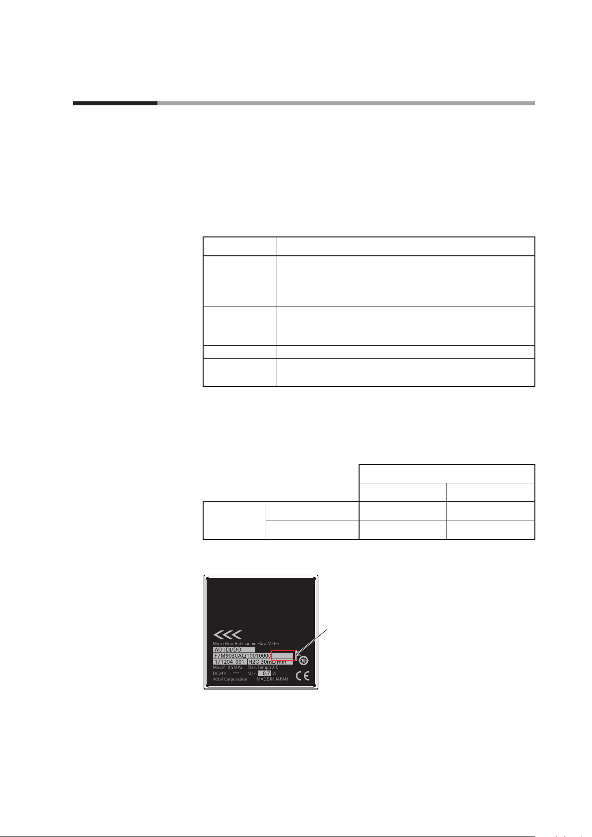
*1. The ID code is printed on the label on the back of the device.
For ver. b and later,
the code is printed as “Ver. _.”
Ver. b
*2. Please download the latest version of the loader from the following website.
https://www.azbil.com/products/factory/factory-product/flowmeter/rate-liquid/
f7m/software/index.html
1
Loader version
Earlier than 2.0.0 2.0.0 or later
*2
1-1
Page 10

Chapter 1. INTRODUCTION
1 - 2 System Requirements
The following system environment is required for use of the loader.
System Environment
Item Description
PC Compatible equipment Windows PC with an Intel CPU
Recommended: Core i3–i7, 1.5 GHz or more. Minimum: 1 GHz
Operating system*
Memory Recommended: 4 GB or more. Minimum: 2 GB
Hard disk Recommended free space: 20 GB or more. Minimum: 10 GB or more
Display Recommended: 1366 × 768 dot or more, 32-bit color or more
Pointing device A mouse or an equivalent device compatible with Windows.
USB port 1 port
Other hardware Adapter for loader
communication cable
USB loader cable USB loader cable (azbil brand, model No. 81441177-001)*
Cable for waterproof connector Cable (azbil brand, model No. F9Y7H_1)
Software Microsoft .NET Framework 4.6
If this software is not installed on the PC, download it from the Microsoft website*
USB loader cable device driver
Install the driver using its installation software, which is different from the installer for the loader.
Adobe Acrobat Reader XI or later version
This software is necessary for viewing PDF user's manuals. If the software is not installed on the PC,
download it from the Adobe's website and install it.
1 *2
Windows10 (64-bit and 32-bit English versions)
Adapter for loader communication cable (azbil brand, model No.
F9Y7A1)
3
4
and install it.
*1. The performance of the loader cannot be guaranteed if it is used on other operating systems.
*2. Specify “Smaller – 100%” (default) as the font size on Windows. Otherwise, loader windows may not be displayed
properly.
*3. Use Rev. 05 or later version of the USB loader cable.
*4. English versionWindows https://www.microsoft.com/en-US/download/details.aspx?id=48130 (as of 3/26/2019)
1-2
Page 11
Hardware Configuration
Connection method
z
Chapter 1. INTRODUCTION
The hardware configuration for loader communication is explained below.
• Turn off the supply of power to the device.
• Remove the cable from the waterproof connector on the device, and connect
the cable to the adapter for loader communication cable with cable B, which is
supplied with the adapter.
• Connect cable A, which is also supplied with the adapter, to the waterproof
connector on the device and to the adapter for loader communication cable.
• The device can now be turned on or off with the power switch on the adapter for
loader communication cable.
For normal operation
Remove the cable from
the waterproof connector
For loader communication
Cable A
(included with the adapter)
The device (F7M)
Cable (F9Y7H_1)
Cable B
(included with the adapter)
Cable (F9Y7H_1)
Windows PC
(with the loader installed)
←
Output
→
←
24 V DC
24 V DC
Adapter for loader communication cable
(F9Y7A1)
Note 1. During loader communication, output from the F9Y7H_1 cable cannot be checked with the loader.
Note 2. The underscore represents a digit that tells the material of the cable.
USB loader cable
(81441177-001)
USB port
1-3
Page 12

Chapter 1. INTRODUCTION
Note
Handling Precautions
• It is also possible, without using cable B, to directly connect the adapter for loader
communication cable to the cable removed from the waterproof connector on the
device.
• To use loader communications, remove the cable from the device waterproof
connector and connect it to the adapter for loader communication cable.
• When handling the cable, make sure that the electrodes of the connector are
free from water drops and dust. Otherwise, a failure or abnormal output might
result. Also, be sure to turn off the device before removing or connecting the
connector. Otherwise, the device or the adapter for loader communication
cable may fail, and the power supply for the equipment may fail or catch fire.
Separately sold products
z
• The adapter for loader communication cable is not water resistant. Water
drops or dust entering inside or accumulating around the electrodes may
damage the device or the adapter, or may cause external devices to catch fire
or fail.
• After using loader communications, remove the cable for the device
waterproof connector from the adapter for loader communication cable,
and insert it all the way into the waterproof connector. If the cable is not
inserted properly, the device's water resistance will be impaired, the device or
connected equipment may fail, and the connected equipment may catch fire.
• Application of excessive force to the plug of the USB loader cable might
interfere with communications. If this happens, reconnect the plug correctly
and restart communications.
• Adapter for loader communication cable (F9Y7A1)
• USB loader cable (81441177-001)
• Cable (F9Y7H_1)*
* The underscore represents a digit that tells the material of the cable.
1-4
Page 13
Chapter 1. INTRODUCTION
1 - 3 Installation
Please download the installer for the loader from the following website (in Japanese only):
https://www.compoclub.com/ The installer file is compressed. Expand it before use. (Expanded file name example:
setup_SLPSP7_en_V1_0_15.msi)
Installing the Loader
The following explanation of the loader installation and screens use 64-bit
Windows 10 as an example.
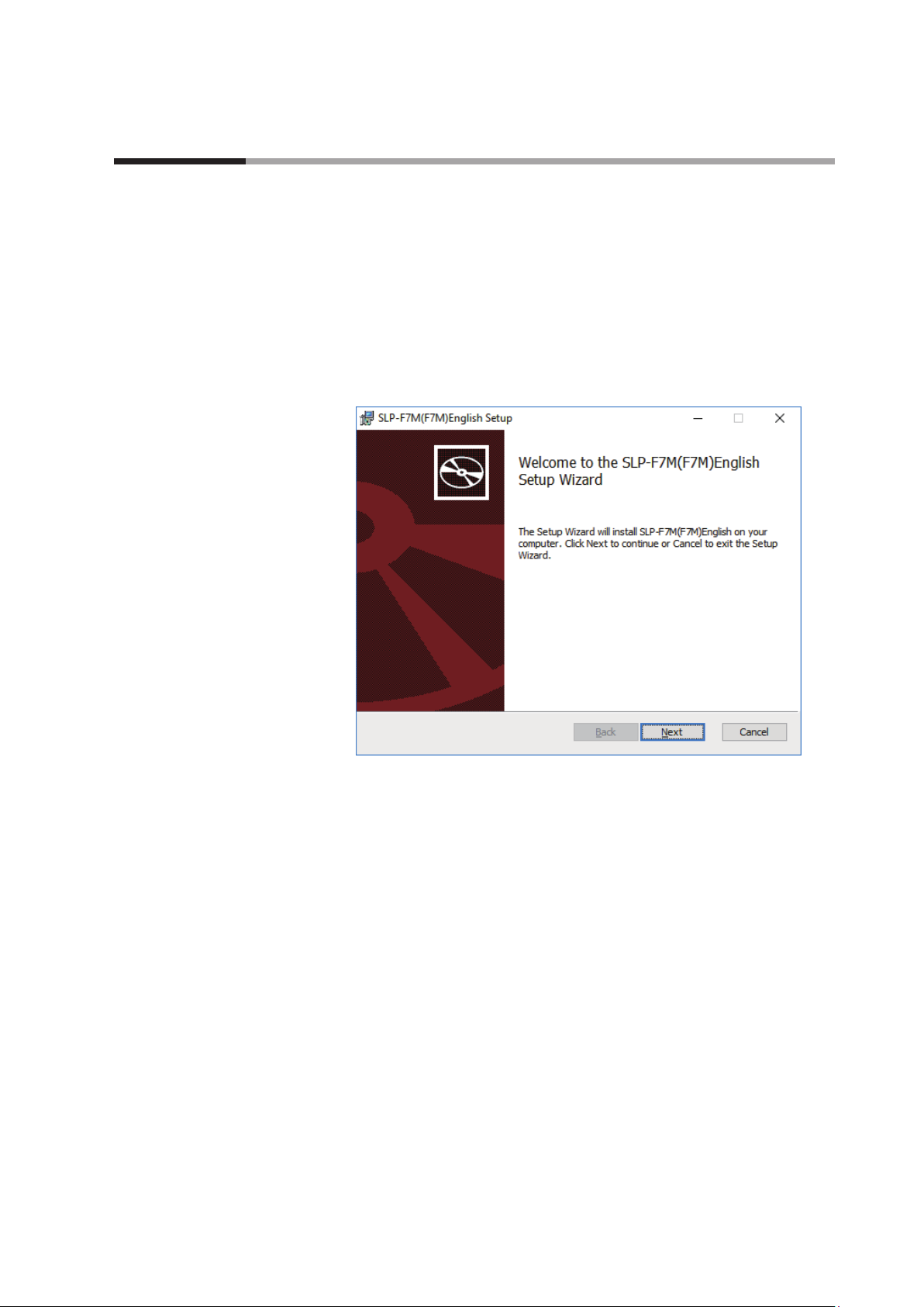
(1) Double-click setup_SLPF7M_en_V☐_☐_☐.msi* to launch the installer.
>> The setup wizard opens.
* ☐ represents a number. For example: setup_SLPF7M_en_V1_0_09.msi
(2) Click the [Next] button.
1-5
Page 14
Chapter 1. INTRODUCTION
>> The following screen is displayed.
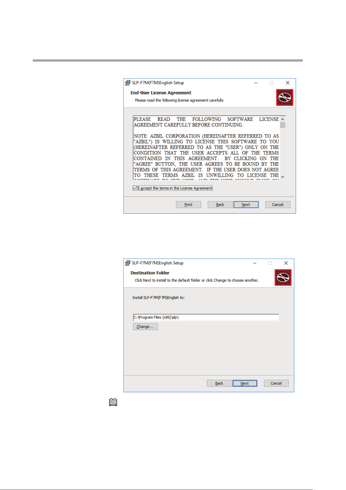
(3) If you accept the software license agreement and wish to install the software,
check the check box for [I accept the terms in the License Agreement] and
click the [Next] button.
>> The following screen is displayed.
1-6
Note
• Click the [Change...] button to change the destination folder.
(4) Click the [Next] button.
Page 15
>> The following screen is displayed.
Chapter 1. INTRODUCTION
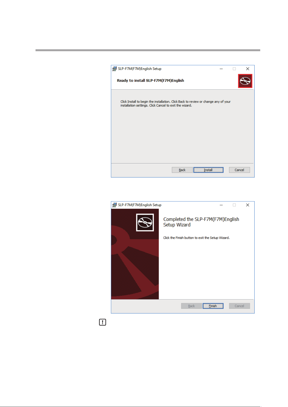
(5) Click the [Install] button.
>> When installation is complete, the following screen is displayed.
Handling Precautions
• A warning message about user account control might appear, depending
on the PC settings. Allow the software to make changes to the computer.
(6) Click the [Finish] button.
This completes the loader installation. Close the installer.
(7) If the installation files are no longer needed, delete the entire folder.
1-7
Page 16
Chapter 1. INTRODUCTION
Installing the USB Loader Cable Device Driver
A device driver must be installed before using the USB loader cable. Follow the
procedure below to install the device driver on the PC.
Installing the device driver
Handling Precautions
• Before installing the device driver, unplug the USB loader cable from the PC.
• Be sure to follow the procedure below when installing the device driver. The
USB cable may not be recognized if the procedure is not followed. If the loader
cable is not recognized, uninstall the device driver and reinstall it.
• If a problem occurs and installation is not successful, uninstall the driver and
reinstall it.
• To install the device driver, administrator rights on the computer are required.
Installation should be done by the administrator or by a user who belongs to
the administrator group.
• A USB loader cable with a label that does not indicate a revision number is not
compatible with Windows 10. (As of 12/11/2017, available USB loader cables have a
label saying “REV.06,” and are compatible with Windows 10.)
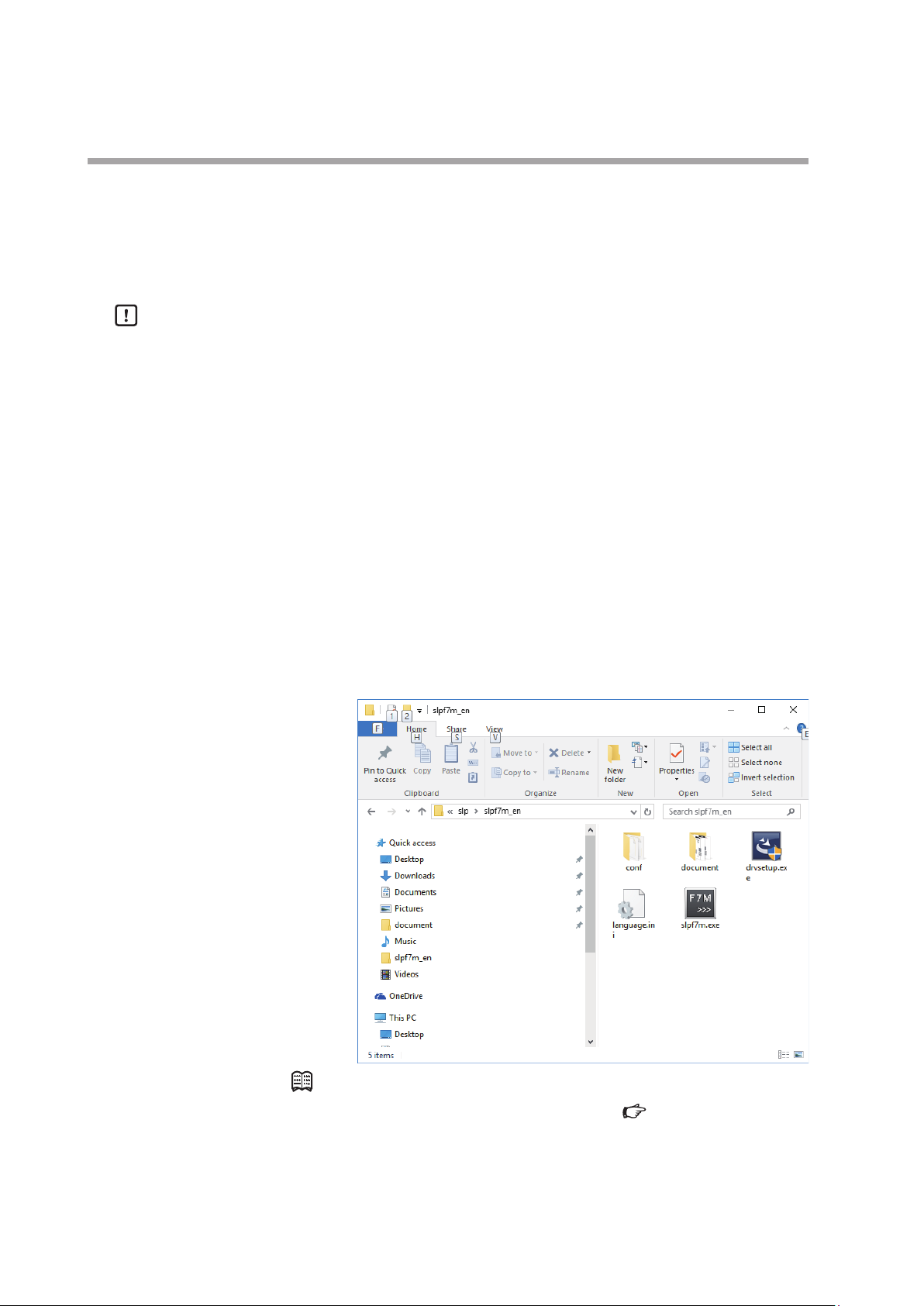
(1) Open the [slpf7m_en] folder where the loader was installed and double-click
drvsetup.exe.
1-8
Note
• If you did not change the destination folder in
(P.1-5), the file is stored in the following default folder:
• 64-bit Windows: C:\Program Files(x86)\slp\slpf7m_en
• 32-bitWindows: C:\Program Files\slp\slpf7m_en
Installing the Loader
Page 17
Chapter 1. INTRODUCTION
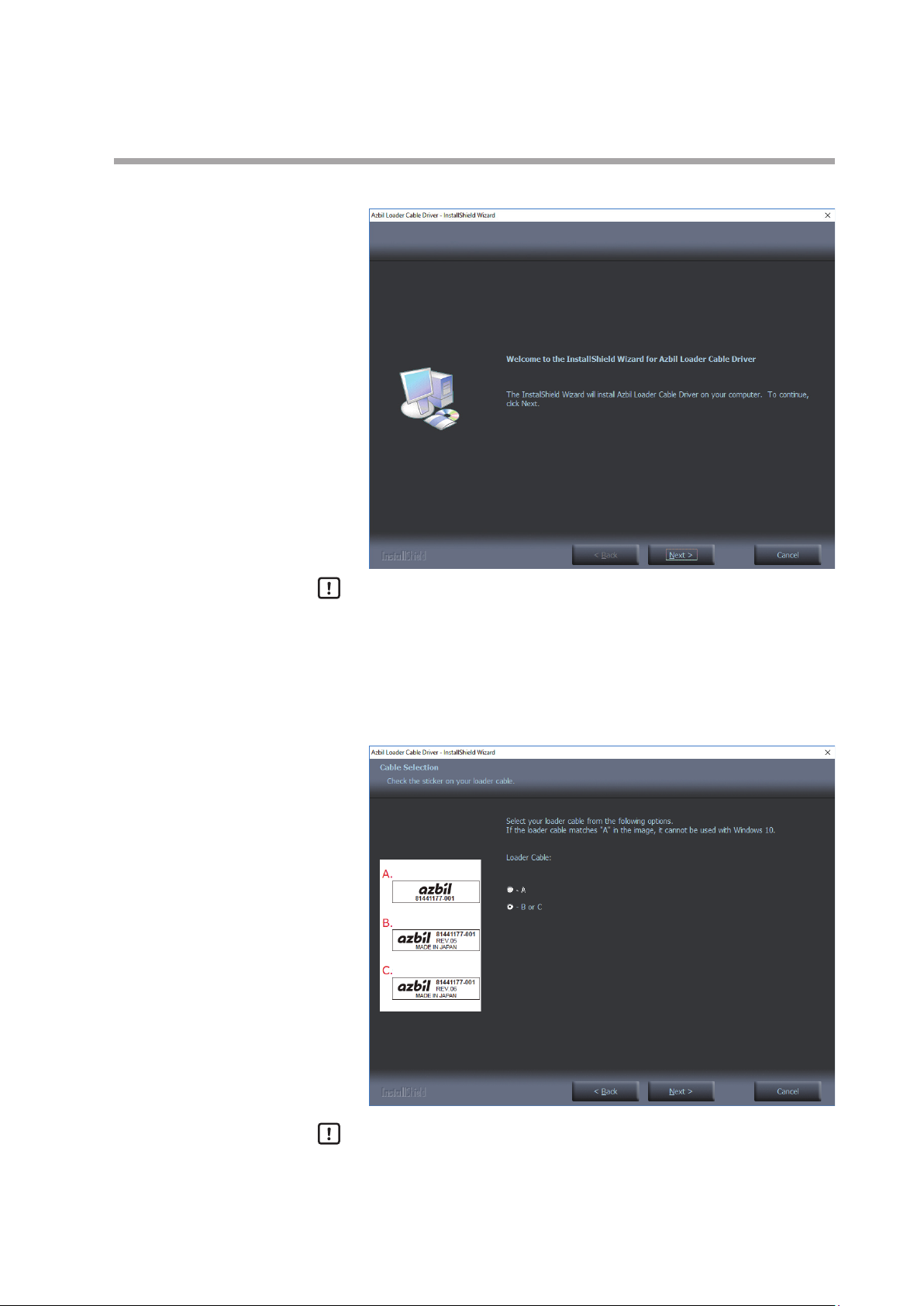
>> The installer is launched and the following window is displayed.
Handling Precautions
• A warning message about user account control might appear, depending
on the PC settings. Click the [Yes] button to allow the software to make
changes to the computer.
(2) Click the [Next ] button.
>> The following screen is displayed.
Handling Precautions
• The USB loader cable with label A cannot be used with Windows 10.
(USB loader cables that are available as of 12/11/2017 have label C with
“REV.06” printed, so they can be used for Windows 10.)
1-9
Page 18
Chapter 1. INTRODUCTION
(3) Select the label code A, B, or C of your USB loader cable in the window, and
click the [Next] button.
>> The following screen is displayed.
Handling Precautions
• If a message saying that the USB loader cable driver has already been
installed on your computer appears even if you uninstalled the driver in
the past, follow the procedure described in
device driver cannot be installed (P.1-12).
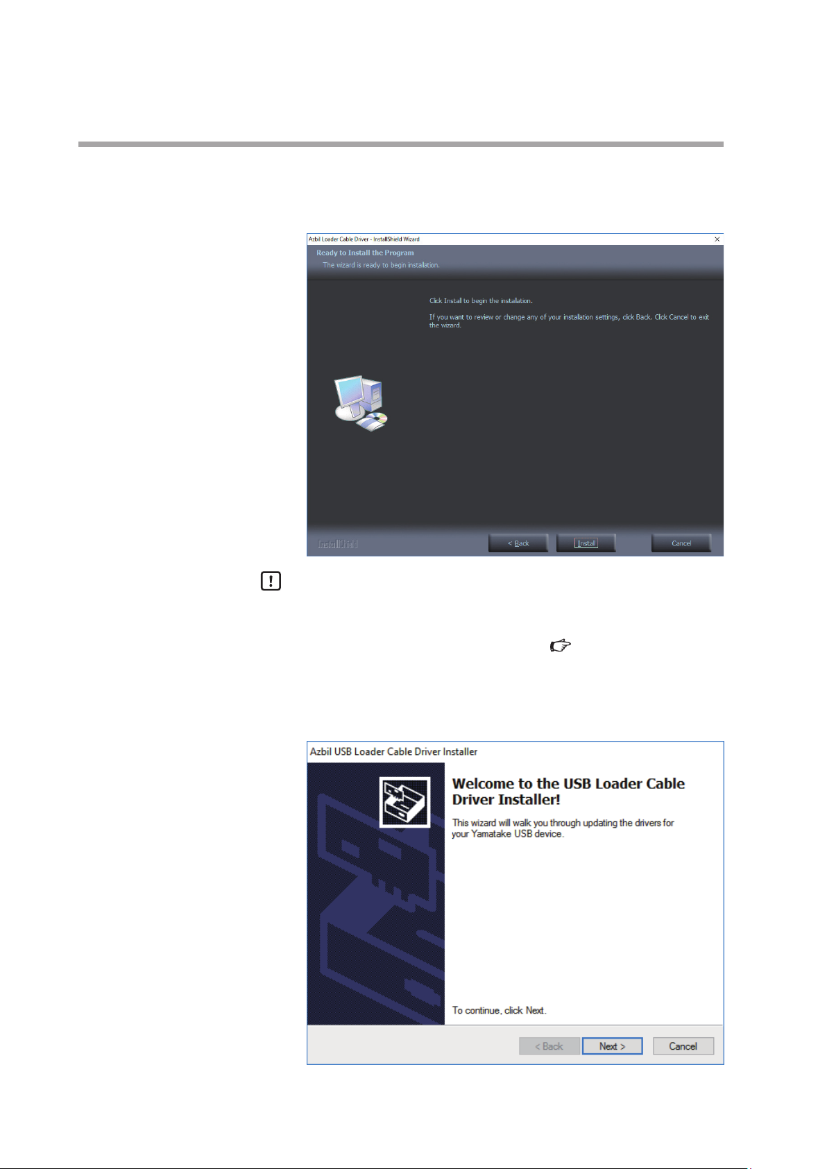
(4) Click the [Install] button.
>> The following screen is displayed.
If the USB loader cable
1-10
Page 19

(5) Click the [Next ] button.
>> The following screen is displayed.
Chapter 1. INTRODUCTION
(6) If you accept the software license agreement and wish to install the software,
select [AGREE] and click the [Next] button.
>> Installation of the device driver starts and the following window is
displayed.
1-11
Page 20

Chapter 1. INTRODUCTION
(7) Click the [Finish] button.
>> The following screen is displayed.
(8) Click the [Finish] button.
Installation of the device driver is complete.
If the USB loader cable device driver cannot be installed
When attempting to install the device driver on a PC on which a USB loader cable
was used in the past, the following window may appear, and it may not be possible
to install the driver, even if the previous device driver has already been uninstalled.
In this case, follow the procedure below.
Step 1. Install tools other than the driver as instructed in the window.
1-12
Page 21

Chapter 1. INTRODUCTION
(1) Click the [Next ] button.
>> Once the installation process is complete, the following screen is displayed.
(2) Click the [Finish] button.
>> The installer for the device driver closes.
Step 2. Follow the procedure described in
(P.1-15).
Step 3. Install the driver following the procedure described in
the USB Loader Cable Device Driver (P.1-8).
Uninstalling the device driver
Installing
1-13
Page 22

Chapter 1. INTRODUCTION
Checking and Installing Microsoft .NET Framework
(1) Right-click the [Start] button and select [Programs and Features].
>> The following screen is displayed.
(2) Select [Turn Windows features on or off ].
>> The following screen appears:
(3) Check that .NET Framework is enabled.
If not, click the checkbox to enable .NET Framework. If “.NET Framework” is
not displayed, the software has not been installed.
After confirming that .NET Framework is enabled, close the window.
Note
• If the software has not been installed on the PC, download it from the
Microsoft website* and install it.
Windows Update to make sure that Windows is in up to date.
* .NET Framework for English versionWindows https://www.microsoft.com/en-
US/download/details.aspx?id=48130 (as of 3/26/2019)
Before installing .NET Framework, execute
1-14
Page 23

1 - 4 Uninstallation
Uninstalling the Loader
(1) Right-click the [Start] button and select [Programs and Features].
(2) Double-click “SLP-F7M (F7M) English” under [Name].
Chapter 1. INTRODUCTION
>> The following screen is displayed.
>> The following screen is displayed.
(3) Click the [Yes] button. The program and related files will be deleted.
Handling Precautions
• A warning message about user account control might appear, depending
Uninstalling the device driver
Handling Precautions
• Before uninstalling the device driver, unplug the USB loader cable from the PC.
• After uninstalling the driver, restart the computer.
• To uninstall the driver, administrator rights on the computer are required.
Installation should be done by the administrator or by a user who belongs to
the administrator group.
on the PC settings. Click the [Yes] button to allow the software to make
changes to the computer.
1-15
Page 24

Chapter 1. INTRODUCTION
(1) Right-click the [Start] button and select [Programs and Features].
>> The following screen is displayed.
(2) Double-click “Azbil Loader Cable Driver.”
>> The following screen is displayed.
(3) Click the [Yes] button.
>> The device driver is deleted and the following window is displayed.
1-16
(4) Click the [Finish] button.
(5) Restart the computer.
Page 25

Chapter 2. STARTING AND EXITING THE LOADER
Handling Precautions
• If there are multiple USB ports, connect the USB loader cable to the same port
every time. If it is connected to a different port, driver reinstallation might be
required.
• Do not unplug the loader cable from the PC while the loader is running. Doing
so may cause faulty loader operation.
• Before starting the loader, close all other application software. Otherwise,
the loader may not work properly due to a particular combination of other
applications and drivers.
• In the Windows settings, select [Control Panel] → [Region] and press the
[Additional settings] button to check that ".” is set for [Decimal symbol]. If any
other symbol is set, the loader will not work properly.
• Check the Windows power option settings and make sure that the PC will not
automatically enter sleep mode. If the PC enters sleep mode, communication
with the device will stop.
Starting the loader
• For details on Windows and PC settings, refer to the user’s manuals provided
with Windows and your PC.
• Do not start multiple instances of the loader program at the same time. Doing
so may cause faulty loader operation.
Double-click the [SLP-F7M (F7M) English] icon on the desktop, or click the [Start]
button at the bottom left of the screen and select [All Apps] → [SLP] → [SLP-F7M
(F7M) English].
>> The following splash screen is displayed for 3 seconds.
>> After 3 seconds, the following initial screen is displayed.
2-1
Page 26

Chapter 2. STARTING AND EXITING THE LOADER
Note
• For details on the OS or the mouse, see the user’s manuals provided with
those products.
Exiting the loader
Select [File] → [Exit] or click the [×] icon in the upper right corner of the screen.
>>The loader closes.
Checking the communication port number
Select [Control Panel] → [Device Manager] and see [Port (COM and LPT)] to check
the COM number for “Yamatake USB Loader Comm.port.”
2-2
Page 27

Chapter 3. HOW TO USE THE LOADER
3 - 1 Overview
Overview of functions
Connect the loader to the device in order to change the parameters, monitor the
flow rate and device status, and for other operations (zero point adjustment, etc.).
Parameters and monitoring results can be saved to a file. The saved file can be
opened to check the data, and parameters can be written to the device.
In addition, with the device not connected, it is possible to edit new parameter
settings and save them to a file, and connect the device afterward to write the
parameters to the device.
Handling Precautions
• As a result of internal calculation (rounding), the value of the least significant
digit displayed on the loader might differ from the value the device has
internally.
• As a result of internal calculation, the least significant digit near either the
range high or range low limit may be judged to be outside the range limit,
with the result that the number cannot be input.
Components of the screen
Menu bar
Toolbar
Tab
Tree view
Status bar Panel view
Name Description
Menu bar All functions of the loader can be accessed from here by selecting any of the
Toolbar Icons for frequently used functions of the loader are provided for easy access to
Tab Information on the device is sorted into tabs.
Tree view Items in the tab are grouped by the device functions.
Panel view Information on the device (status, parameters, etc.) is displayed. Parameter
Status bar The status of communications between the loader and the device is displayed.
menus with the mouse or keys.
the necessary function.
Clicking any of the tabs displays the tree of related items.
Device info.: Model No., etc.
Parameters: Device parameters (configurable in this tab)
Monitor: Process values, abnormal status, etc., of the device
Selecting any of the groups displays related device information in the panel
view.
settings can be changed, with the exception of the items with a gray background.
3-1
Page 28

Chapter 3. HOW TO USE THE LOADER
Loader functions
The table below shows the functions of the loader. They can be executed from
the menu bar.
The functions with icons can also be executed from the toolbar.
parameters)
• File (F): The submenu includes file operations and exit from the
• Comm. (E): The submenu includes the function to execute before
• Parameters (P): The submenu includes functions for reading all
• Monitor (M): The submenu includes functions for starting and
• Device operation (O): Certain device functions can be executed from the
• Help (H): Loader information, etc., can be displayed from the
3 - 4 List of Parameters (P.3-13)(for device information and a list of
loader.
starting communications with the device.
parameters from the device and writing all parameters
to the device.
stopping monitoring.
submenu.
submenu.
Menu bar
Menu Submenu
File New Creates a file of parameters to be written to a device, while
the loader is not connected to the device.
Open Reads parameters that were saved to a file and displays them
on the loader screen. The parameters can be changed and
written to the device.
Save Saves the current parameters. Ctrl + S
Rename and save... Saves the current parameters to a file with a different file
name.
Exit Ends the loader program.
Comm. Comm. settings Communication settings of the loader can be changed. Ctrl + G
Activate comm. Execute this function before starting communication. Ctrl + A
Parameter
Read all parameters
Reads device information and parameters from the device. F1
Overview of functions Toolbar Shortcut keys
Ctrl + N
Ctrl + O
Shift + Ctrl + S
–
Alt + F4
from device
Write parameters to
device
Monitor Start monitoring Reads the process value and device status from the device
End monitoring Ends updating of values on the monitor screen. F5
Device
operation
Help User's Manual for SLP-F7M
Zero point adjustment Automatically adjusts the zero point of the instantaneous flow
Smart Loader Package for
F7M (PDF)
F7M Micro Flow Rate
Liquid Flow Meter User’s
Manual (PDF)
Version information The version information for the loader, etc., is displayed.
Writes only parameters to the device.
Device information is not written.
Settings cannot be written if the model No. of the connected
the device differs from the number in the loader.
and updates the monitoring display.
–
rate.
The user's manual for the loader can be viewed.* – –
The user's manual for the device can be viewed.* – –
– –
F2
F4
F6
* Adobe Acrobat Reader XI or later version is required to view the document.
3-2
Page 29

Chapter 3. HOW TO USE THE LOADER
3 - 2 Connecting the Loader to the Device
In order to check or change the data on the device, the loader must first be connected to the device.
The procedure for connection is as follows.
Steps 1–2: Connect the PC to the device.
Step 3: Start the loader.
Steps 4–5: Set the communication conditions.
Steps 6–8: Execute “Activate comm.”
Handling Precautions
• After the above procedure, a different device can be connected without
exiting the loader. To do so, change the device that is connected to the PC, and
activate communication with the device using steps (6)–(8).
Procedures for device connection
In order to connect the loader to the device, it is necessary to specify
communication settings for the loader and activate communication with the device.
(1) Turn the device off.
(2) Connect the device to the PC.
(3) Start the loader.
(4) Select [Comm. (E) ] → [Comm. settings] on the menu bar, or click the
button on the toolbar.
>> The following screen is displayed.
3-3
Page 30

Chapter 3. HOW TO USE THE LOADER
(5) In the COM port field, select the COM number for the USB loader cable, and
click the [OK] button.
>> The window closes.
Note
• To identify which of multiple communication ports is used, in Windows select
[Control Panel] → [Device Manager] and view [Ports (COM & LPT)] to check
the communication port number for “Yamatake USB Loader Comm. Port.”
(6) Select [Comm. (E)] → [Activate comm.] on the menu bar, or click the
button on the toolbar.
>> The following screen is displayed.
(7) Turn off the power switch on the adapter for loader communication cable.
Power switch
3-4
(8) Turn on the power switch and click the [OK] button within 10 seconds.
>> If communication activation is successful, the following screen is displayed.
Click the [End] button. Now you can execute functions that require
communication with the device.
Page 31

Chapter 3. HOW TO USE THE LOADER
>> If communication activation failed, the following screen is displayed.
Click the [End] button. Check the communication settings of the loader, the
state of the device, and the connection to the device, and then repeat steps
(1)–(8).
3-5
Page 32

Chapter 3. HOW TO USE THE LOADER
3 - 3 Checking and Changing Parameters
Parameters can be checked or changed by the following methods.
· Create a parameter file
· Open a parameter file
· Read all parameters from the device*
Changed parameters can be written to the device or saved by the following methods.
· Write all parameters to the device*
· Save the file
· Rename and save the file
* It is necessary to connect the loader to the device in advance. ( 3 - 2 Connecting the Loader to the Device (P.3-3))
Creating a parameter file without connecting the loader to the device
It is possible to create a parameter file for a device before connecting it to the loader,
and to write the saved parameters to the device afterward.
(1) Select [File] → [New] on the menu bar, or click the
>> The following window is displayed:
button on the toolbar.
3-6
(2) Select the model number of the device whose parameter file is to be created,
and click the [OK] button.
>> The following screen is displayed.
Handling Precautions
• The last letter is the ID code. Please select the model number that is
followed by the ID code printed on the label on the back of the device.
Page 33

Chapter 3. HOW TO USE THE LOADER
Handling Precautions
• The following device information is displayed after a model number is
selected.
Model No.: The model number selected in the [Select model number]
window.
(The digits representing the device specifications that do not affect the
loader function are displayed with hyphens.)
Serial No.: 0
Signal type: Analog output + DI + DO
Firmware version: 0000
(3) Check that the model number and the signal type are correct. Click the
[Parameters] tab and select a parameter group in the tree view, and make
necessary changes to the parameters.
(4) Select [File] → [Rename and save...] on the menu bar, or click the button on
the toolbar.
3-7
Page 34

Chapter 3. HOW TO USE THE LOADER
(5) Enter any name in the [File name] field (example: F7M_N1_1.f7m) and click
>> The following screen is displayed.
the [Save] button.
Note
•
Checking parameters of the connected device
The method of reading and displaying all parameters of the connected device is
explained below.
“All parameters” means all data on the [Device info.] and [Parameters] tabs.
(1) Connect the loader to the device. (
Device (P.3-3))
(2) On the menu bar, select [Parameters] → [Read all parameters from device].
>> The following screen is displayed.
Writing parameters to the device (P.3-10), Saving parameters to
a file (P.3-11) (for opening saved files and writing parameters to the device)
3 - 2 Connecting the Loader to the
3-8
(3) Click the [OK] button.
Page 35

>> The following screen is displayed.
(4) Click the [OK] button.
>> The following screen is displayed.
Chapter 3. HOW TO USE THE LOADER
(5) Click the [Parameters] tab and select the item to check in the tree view.
>> The following screen is displayed.
3-9
Page 36

Chapter 3. HOW TO USE THE LOADER
Writing parameters to the device
This section describes the procedure for writing parameters to the device.
After reading parameters to the loader, perform the following operations.
Handling Precautions
• Parameters cannot be written to the device if the model number of the device
is different from the number in the [Device info.] tab.
However, because the underlined digits in the following example represent
the device specifications that do not affect the loader function, even if there
are discrepancies in these digits, parameters can be written to the device.
Example: F7M9010AQ100100Y0
(1) Activate communication with the device.
(
3 - 2 Connecting the Loader to the Device (P.3-3))
(2) On the menu bar, select [Parameters] → [Write parameters to the device], or
click the
>> The following screen is displayed.
(3) Click the [OK] button.
>> The following screen is displayed.
button on the toolbar.
3-10
(4) Click the [OK] button.
Page 37

Saving parameters to a file
Parameters that were read from the device or that were changed can be saved to a
file using the following procedure.
Chapter 3. HOW TO USE THE LOADER
(1) Select [File] → [Rename and save...] on the menu bar, or click the
the toolbar.
>> The following screen is displayed.
button on
(2) Enter any name in the [File name] field and click the [Save] button.
Checking saved parameters
This section describes the procedure for displaying data (parameters) that have
been saved to a file.
(1) Select [File] → [Open] on the menu bar, or click the
button on the toolbar.
>> The following screen is displayed.
3-11
Page 38

Chapter 3. HOW TO USE THE LOADER
(2) Select the parameter file to open (extension: f7m) and click the [Open] button.
>> The following screen is displayed.
(3) Select a tab and an item in the tree view to check parameter settings.
3-12
Page 39

Chapter 3. HOW TO USE THE LOADER
3 - 4 List of Parameters
The following tables show the parameters that can be accessed by the loader.
Note
• F7M Micro Flow Rate Liquid Flow Meter User’s Manual CP-SP-1421E (for
details on parameters)
[Device info.] tab
Displays information such as model number. The settings of these parameters
cannot be changed.
Parameters Unit Description Factory default
Model No. – Device model No. (17 chars.) + ID code (1 alphabetical
char.) (In some cases, the ID code is not printed.)
Example: F7M9030AQ10010000b
Serial No. – Serial number of the device represented by a 9-digit
number
Signal type – Indicates the signal type of the device. Analog output + DI + DO
Firmware version – Indicates the firmware version of the device. –
Depends on the device
specifications.
Depends on the device.
3-13
Page 40

Chapter 3. HOW TO USE THE LOADER
[Parameters] tab
Parameters Unit Description Factory default
DI settings DI function – Zero point adjustment
Error reset
Liquid type selection*
DO settings DO function – Flow rate event 1
Flow rate event 2
Error indication output
Totalizer pulse output
DO polarity – Direct (normally open)
Reverse (normally closed)
Analog output
settings
Flow rate
correction
Totalizer pulse flow
rate
Upper limit validity – Invalid
Flow rate upper limit % FS 0.00–100.00 100.00
Hysteresis upper limit % FS 0.00–10.00 0.00
Delay upper limit s 0.0–60.0 0.0
Lower limit validity – Invalid
Flow rate lower limit % FS 0.00–100.00 0.00
Hysteresis lower limit % FS 0.00–10.00 0.00
Delay lower limit s 0.0–60.0 0.0
Span correction factor – 0.000–2.000 1.000
Zero-point correction V -1.000 to +1.000 0.000
Output at error – Present value
Voltage at error V 0.600–6.000 0.600
Flow rate CCF 1 – These parameters cannot be changed
Zero point adjustment 1mW 0.00
Flow rate CCF 2* – 1.000
Zero point adjustment 2*mW 0.00
mL/pulse 0.01, 0.1, 1, 10 0.1
Valid
Valid
Last good value (before error)
Specified value (set in [Voltage at error])
using the [Write parameters to the
device] menu. Write the settings from
the [Monitor] tab.
Error reset
Flow rate event 1
Direct
Valid
Valid
Present value
1.000
Offset correction value mL/min -10.00 to +10.00 0.00
Low-flow cutoff value % FS 0.0–100.0 1.0
Filter time constant s 0.0–60.0 0.0
Function
settings*
*Available on devices with ID code “b” or later
Automatic setting of
flow rate correction
factor (CCF)*
Temperature-based
correction (for water)*
Display ON/OFF using
DI status*
– ON
OFF
– ON
OFF
– ON
OFF
OFF
ON
OFF
3-14
Page 41

3 - 5 Checking Measured Values and Status
Displaying measured values and status of the device
(1) Connect the loader to the device. ( 3 - 2 Connecting the Loader to the
Device (P.3-3))
Chapter 3. HOW TO USE THE LOADER
(2) Obtain device information by executing steps 1 to 4 in
parameters of the connected device (P.3-8). If you have already executed
steps 1 to 4, this process is unnecessary.
(3) Click the [Monitor] tab and select the item to display in the tree view.
Monitoring information has not yet been read from the device. (The following
are the screens displayed when [Monitor] → [Process value] is selected)
(4) Click the [Monitor] → [Start monitoring] on the menu bar, or click the
button on the toolbar.
Checking
>> The following screen is displayed. The loader starts updating values and
information. When monitoring is in progress, “Monitoring” at the bottom
left of the screen is displayed in green and the word “Communicating...”
blinks.
3-15
Page 42

Chapter 3. HOW TO USE THE LOADER
3 - 6 Immediate Writing of Parameters
How to write monitoring parameters to the device immediately
Only when monitoring is in progress, parameters with the [Write] button can be
written to the device immediately.
(1) Connect the loader to the device. (
Device (P.3-3))
(2) Obtain device information by executing steps 1 to 4 in
parameters of the connected device (P.3-8). If you have already executed
steps 1 to 4, this process is unnecessary.
(3) Click the [Monitor] tab and select the desired item in the tree view. At this
point monitoring information has not yet been read from the device. [Write]
buttons are disabled and the monitoring parameters cannot be written to the
device immediately.
(The following figure shows the screen after clicking [Monitor] → [Fluid
settings correction].)
3 - 2 Connecting the Loader to the
Checking
(4) Click the [Monitor] → [Start monitoring] on the menu bar, or click the
button on the toolbar.
>> The following screen is displayed.
3-16
Page 43

Chapter 3. HOW TO USE THE LOADER
The loader starts updating values and information.
When monitoring is in progress, “Monitoring” at the bottom left of the screen
is displayed in green and the word “Communicating...” blinks.
Under these conditions, monitoring parameters can be written to the device
immediately by pressing the [Write] button.
(5) Change the value or option selection for the desired monitoring parameter
and press the [Write] button next to it. Only the setting for that monitoring
parameter is written to the device.
3-17
Page 44

Chapter 3. HOW TO USE THE LOADER
3 - 7 List of Monitoring Parameters
[Monitor] tab
Parameters Unit Description
Process value Instantaneous
flow rate
Abnormal status – Indicates the type of abnormal status. –
Fluid settings
correction*
Instantaneous
1
flow rate
Totalized flow mL Indicates the total volume of flow at that point in time.*
Totalized flow
count up
Liquid type – Indicates the currently selected liquid type. The type can be
Flow rate CCF 1 – Indicates the flow rate correction factor for liquid type 1. The
Zero point
adjustment 1
Flow rate CCF 2 – Indicates the flow rate correction factor for liquid type 2. The
Zero point
adjustment 2
Abnormal
Error – An error has a significant impact on the operation of the device.
status
Alarm – An alarm affects the measurement of flow rate.
Warning – A warning has a small impact on the measurement of flow rate.
Information – This is not technically an abnormal status. Information is
Sensor
information
Flow path
temperature
Circuit
temperature
Heater power mW Displays power consumption by the heater used for flow rate
Factory
default
mL/min Indicates the value calculated from the measured flow rate signal. –
mL/min Indicates the value calculated from the measured flow rate signal. –
1
– Totalizing of the flow volume can be started or stopped.*
1 *2
Stop
Start
Stop
Stop and reset counter to 0
Liquid
changed.*
1 *2
type 1
Liquid type 1
Liquid type 2
1.000
value can be changed.*
1 *3
0 to 100.000
mW Indicates the amount of zero point adjustment for liquid type 1.
The value can be changed.*
1 *3
0.00
-5.00 to +5.00
1.000
value can be changed.*
1 *3
0 to 100.000
mW Indicates the amount of zero point adjustment for liquid type 2.
The value can be changed.*
1 *3
0.00
-5.00 to +5.00
Chapter 4. TROUBLESHOOTING (for details and corrective
actions)
Chapter 4. TROUBLESHOOTING (for details and corrective
actions)
Chapter 4. TROUBLESHOOTING (for details and corrective
actions)
displayed for reference.
Chapter 4. TROUBLESHOOTING (for details and corrective
actions)
°C Displays an approximate temperature in the flow path. –
°C Displays the approximate temperature of the circuit. –
measurement.
–
–
–
–
–
–
3-18
Page 45

Chapter 3. HOW TO USE THE LOADER
Parameters Unit Description
Abnormal
status code
*1. Available on devices with ID code “b” or later.
*2. The setting can be changed only when monitoring is in progress.
Changes are temporary and the parameter is reset to the setting at the time when the device was shipped if the device
is turned off and back on.
*3. The setting can be changed only when monitoring is in progress.
Abnormal status
code 0
Abnormal status
code 1
Abnormal status
code 2
Abnormal status
code 3
Abnormal status
code 4
Abnormal status
code 5
Abnormal status
code 6
Abnormal status
code 7
– For maintenance –
– For maintenance –
– For maintenance –
– For maintenance –
– For maintenance –
– For maintenance –
– For maintenance –
– For maintenance –
Factory
default
3-19
Page 46

Chapter 3. HOW TO USE THE LOADER
3 - 8 Operating the Device
Adjusting the zero point
Note
• To reset the zero point of a device with ID code “b” or later to the value at the
time when the device was shipped, set [Zero point adjustment 1] and [Zero point
adjustment 2] to “0.00” (the value at the time of shipment).
( 3 - 6 Immediate Writing of Parameters
• If a device’s ID code is not indicated, it is not possible to restore the zero point
setting at the time when the device was shipped using the loader.
Instead, use the switch on the device to restore the setting.
For details, please refer to Micro Flow Rate Liquid Flow Meter Model F7M User’s
Manual (CP-SP-1421E).
• If [Automatic setting of flow rate correction factor (CCF)] is enabled, the CCF
based on the amount of adjustment after zero point adjustment is automatically
set. If this function is used to automatically set the CCF, flow rate accuracy is not
guaranteed. For higher accuracy, use the set value as a guideline for setting the
CCF manually.
Handling Precautions
• When zero point adjustment is in progress, do not turn off the device.
• Parameters other than zero point adjustment are written to the device by
[Writing all parameters], but the amount of zero point adjustment is written to
the device when zero point adjustment is complete.
The procedure for adjusting the zero point of the instantaneous flow rate after
connecting the loader to the device is given below.
(1) Connect the loader to the device. (
(2) Obtain device information by executing steps 1 to 4 in
(3) Select [Device operation] → [Zero point adjustment] on the menu bar.
3 - 2 Connecting the Loader to the
Device (P.3-3))
Checking
parameters of the connected device (P.3-8). If you have already executed
steps 1 to 4, this process is unnecessary.
3-20
>> The following screen is displayed.
Page 47

Chapter 3. HOW TO USE THE LOADER
(4) Check that the pipe is full of fluid and that the fluid is not moving, and then
click the [OK] button.
>> The following window is displayed.
>> When zero point adjustment is complete, the following screen is displayed.
(5) Pressing the [OK] button returns the display to the original screen.
3-21
Page 48

-MEMO-
Page 49

Chapter 4. TROUBLESHOOTING
Types of abnormal status
There are four types of abnormal status of the device: Error, alarm, warning, and
information.
Abnormal status can be checked by the loader.
Abnormal status of the device Description
Error An error has a significant impact on the operation of this device. If an error occurs,
flow rate measurement stops.
If the problem is caused by a transient failure such as electrical noise, the device may
return to normal after the power is turned off and back on. If not, request repair.
Alarm An alarm affects the measurement of flow rate.
If an alarm occurs, flow rate measurement continues, but the accuracy of the flow
rate is not guaranteed.
Warning A warning has a small impact on the measurement of flow rate.
If a warning occurs, digital output remains off when “DO function" is set to “Error
indication output.”
Whether a warning has occurred can be checked with the LED indicator or by the
loader.
If a warning occurs, flow rate measurement continues.
Information This is not technically an abnormal status. Information is displayed for reference.
Abnormal status can be checked by the loader.
Abnormal status and corrective actions
Type Er : Error
Al : Alarm
Wn : Warning
Inf : Information
Automatic recovery ✓ : Yes (when the cause is removed, the abnormal status
indication disappears)
– : No
No. Type Description Likely cause Corrective action
0 Al Zero point adjustment
error
(correction of more than
±40 % FS)
Wn Zero point adjustment
completed
(correction of more than
±25 % FS)
Inf Zero point adjustment
completed.
(succeeded)
The zero point was adjusted when
the fluid was moving.
Zero point adjustment succeeded. –
Check that the pipe is full of the
fluid to be measured and that
the fluid is not moving, and try
again.
Automatic
recovery
✓
4-1
Page 50

Chapter 4. TROUBLESHOOTING
No. Type Description Likely cause Corrective action
1 Wn Empty (flow path not full) The flow path of this device has
Fill the flow path with the fluid.
Automatic
recovery
not been full for some time.
Inf Flow rate measurement
error
A flow rate measurement error
occurred due to a cause such as
bubbles in the flow path of the
Check for problems in the
installation environment or
instrumentation.
device.
2 Wn Accuracy-guaranteed
flow rate exceeded
Fluid is flowing at a rate greater
than the rated (accuracy-
Use this device within the rated
flow rate range.
guaranteed) flow rate.
3 Wn Analog output range
exceeded
4 Wn Parameter error
(1) Checksum error
(2) Number of write
cycles exceeded
The rated flow rate was exceeded,
or an analog output correction
parameter value is invalid.
(1) A checksum error occurred
during parameter data reading
or writing.
(2) Parameters were written more
than the specified number of
Use this device within the rated
flow rate range.
Set a valid parameter value.
(1) Write parameters again.
(2) Replace the product.
times.
5 Wn Watchdog time-out A reset by a communication
command, or malfunction due to
electrical noise, etc.
6 Al Flow path or circuit
temperature out of range
Wn The fluid temperature or the
The sensor unit has failed.
ambient temperature does not
meet the specified operating
conditions.
If the warning persists after
turning the power off and back
on, request repair.
•
Check that the fluid
temperature and the
ambient temperature meet
the specified operating
conditions.
•
If the alarm persists after
turning the power off and
back on, request repair.
7 Al Measurable flow rate
exceeded
8 Al Totalizer pulse output
error (flow over range)
The flow rate is greater than 115
% of the measurable range.
When totalizer pulse was being
output, the flow rate exceeded
Use this device within the rated
flow rate range.
Use this device within the rated
flow rate range.
the rated measurable range for a
certain period of time.
Wn When totalizer pulse was being
output, the flow rate far exceeded
the rated measurable range for a
certain period of time.
9 – (Not used) – – –
10 Al Heater control error The heater, temperature sensor,
or electric circuit has failed, so the
heater cannot be controlled.
11 Er Parameter error A type of parameter not
supported by this device, or
an illegal parameter value, was
downloaded by the loader.
Al Parameter mismatch Parameter values are abnormal,
If the alarm persists after turning
the power off and back on,
request repair.
If the error, alarm, or information
persists after changing the
parameter and turning the
power off and back on, request
repair.
etc.
Inf Out-of-range parameter Parameter values are out of range.
✓
✓
✓
–
–
–
✓
✓
✓
–
4-2
Page 51

Chapter 4. TROUBLESHOOTING
No. Type Description Likely cause Corrective action
12 Er Nonvolatile memory error The data in the device is corrupt. If the error or information
Inf Backup parameter error The data in the backup area is
corrupt.
persists after changing the
parameter setting and turning
the power off and back on,
request repair.
13 Er Software execution error
14 Er Hardware error
15 Er Program ROM error A data discrepancy was detected
•
The heater or temperature
sensor has failed.
•
The electric circuit has failed.
•
The heater or temperature
sensor has failed.
•
The electric circuit has failed.
in a cyclic redundancy check
(CRC) of the ROM.
If the error persists after turning
the power off and back on,
request repair.
If the error persists after turning
the power off and back on,
request repair.
If the error persists after turning
the power off and back on,
request repair.
Automatic
recovery
–
–
–
–
–
4-3
Page 52

Chapter 4. TROUBLESHOOTING
Error messages and corrective actions
Menu Message Description Corrective action
[Comm. (E)] →
[Comm. settings]
[Comm. (E)] →
[Activate comm.]
[File] → [New] No model number has been
[File] → [Open] The model is not supported by
No COM port has been selected. The [OK] button was pressed
Communication activation failed.
Please check the communication
settings of the loader, the state of
the device, and the connection to
the device, and then try again.
selected.
the loader.
Reading of the file failed.
The read data contains errors. The file could not be opened
[File name]
File not found.
Check the file name and try again
with no COM port selected.
Communication activation
failed and the loader cannot
communicate with the device.
The [OK] button was pressed
with no model number
selected.
The selected file is for a model
that is not supported by the
loader, so the file could not be
opened.
due to errors in the file.
The file is probably corrupt.
The specified file cannot be
opened because the loader
cannot find it.
Select the COM port that is
assigned for communications
with the device, and click the
[OK] button.
Please check the
communication settings of the
loader, the state of the device,
and the connection to the
device, and then try again.
A model number must be
specified. Select the model
number of the device to be
connected and press the [OK]
button.
If a new version of the loader is
available on the Azbil website
(Compo Club), it might be
possible to open the file by
upgrading the loader.
If the file still cannot be opened,
it might be corrupt. Take the
same corrective action as for
“The read data contains errors.”
Specify the parameters again
and save them to a file.
(Execute [Read all parameters
from device] or select [File] →
[New] to display parameters,
change the settings, and save
them to a file.)
Please enter the correct file
name.
[File] → [Save]
[File] → [Rename
and save...]
4-4
No file is open. The user attempted to save a
[File name] already exists.
Do you want to replace it?
[File name]
This file is set to read-only
Try again with a different file
name.
[File name]
You don't have permission to save
in this location.
Contact the administrator to
obtain permission.
Would you like to save in the
[Document] folder instead?
file but no file was open.
A file with the same name was
found when [Rename and
save...] was executed.
It is possible to overwrite
the file data with the current
parameter settings.
The specified file is read-only
and cannot be overwritten.
You do not have access rights
for the specified destination
folder.
Execute [Rename and save...].
To overwrite the data, press the
[Yes] button.
If you wish not to overwrite
the data, press the [No] button,
change the file name, and save
it.
Change the file name and save
it.
To save the file to the
Documents folder, press the
[Yes] button.
To save the file to another
folder, select a folder that you
are permitted to access and
save the file.
Page 53

Chapter 4. TROUBLESHOOTING
Menu Message Description Corrective action
[Parameters]
→ [Read all
parameters from
device]
The model is not supported by
the loader.
Reading of parameters failed.
A product other than the
device is connected or the
device model not supported
by the loader is specified, so
parameters cannot be read
from the device.
Check the connected product.
Download the latest version of
the loader software from the
Azbil website (Compo Club),
install the loader, and try again.
[Parameters] → [Write
parameters to the
device]
Reading of parameters failed. Reading of parameters from
the device was aborted
because a communication
error, etc., occurred.
Parameters could not be written
to the device because the model
number of the device is different
from the number specified by the
loader.
The model number in the loader’s
device information must be the
same as the model number of the
connected device.
Model number specified by the
loader: F7M _ _ _ _ _ _ _ _
Model number of the connected
device: F7M _ _ _ _ _ _ _ _
Parameters could not be written
to the device because some of the
values were invalid.
Please specify valid values for
the following items and then try
again.
Writing of parameters failed. Writing parameters to the
Parameters could not be
written to the device because
the model number of the
connected device is different
from the model number
currently specified for work
using the loader.
Parameters could not be
written to the device because
the specified parameters
include out-of-range values,
or because the combination
of the specified parameters is
prohibited.
device was aborted because
a communication error, etc.,
occurred.
Please check the
communication settings for the
loader, the power to the device,
and the cable connections, and
then try again.
The model number in the
loader’s device information
must be the same as the model
number of the connected
device.
Please correct the value of the
parameter(s) displayed under
the message
and try again.
Please check the
communication settings for the
loader, the power to the device,
and the cable connections, and
then try again.
4-5
Page 54

Chapter 4. TROUBLESHOOTING
Menu Message Description Corrective action
[Monitor] → [Start
monitoring]
[Device operation]
→ [Zero point
adjustment]
[Help] → Menu
to open a user’s
manual
Parameter values The value is out of range. The entered value could not be
Monitoring could not be started
because the model number of
the device is different from the
number specified by the loader.
Please execute reading of all
parameters from the device and
try again.
Model number specified by the
loader: F7M _ _ _ _ _ _ _ _
Model number of the connected
device: F7M _ _ _ _ _ _ _ _
A communication error occurred.
Monitor startup failed.
Monitoring stopped due to a
communication error.
Zero point adjustment failed.
Zero point cannot be adjusted if
the flow rate exceeds the range
(±40 % FS).
Zero point adjustment failed.
Zero point cannot be adjusted if
an error or alarm occurred or if
zero point adjustment has already
been executed by pressing the
operation switch on the device.
Or, a communication error
occurred.
The specified file cannot be
opened.
The input value is invalid. The specified value could not
The number of characters exceeds
the limit.
Monitoring could not begin
because the model number
of the connected device is
different from the model
number currently specified for
work using the loader.
A communication error
occurred during monitor
startup.
A communication error
occurred during monitoring.
The flow rate is outside the
adjustment range.
The zero point cannot be
adjusted if an error or alarm
occurred, if zero point
adjustment is in progress, or if a
communication error occurred.
The software required to
display the user's manual (a
PDF file) is not installed on the
PC.
set because it is out of range.
be set because it includes
non-numeric values such as
letters or double-width Asian
characters, which are not
treated as numeric values.
The character string is too long. The number of characters must
The model number in the
loader’s device information
must be the same as the model
number of the connected
device.
Please check the
communication settings for the
loader, the power to the device,
and the cable connections, and
then try again.
Please check the
communication settings for the
loader, the power to the device,
and the cable connections, and
then try again.
Check that the pipe is full of
fluid and that the fluid is not
moving, and try again.
Remove all errors or alarms, if
any.
If zero point adjustment is
in progress, wait until it is
complete.
If a communications
error occurred, check the
communication settings for the
loader, the power to the device,
and the cable connections.
Then, try again.
Download Adobe Acrobat
Reader XI or later version from
Adobe’s website, install it, and
try again.
Enter a value that is between
the lower and upper limits
that are indicated within
the parentheses next to the
parameter.
Enter a numeric value.
be within the limit.
4-6
Page 55

Chapter 4. TROUBLESHOOTING
Other troubleshooting
Type Message Description Corrective action
Display Values are not displayed properly.
Files cannot be opened.
Other Some or all functions of the
loader (screen display, operation,
etc.) cannot be executed.
If a symbol other than “.” is set
as the decimal point symbol
in the Windows settings, the
loader will not work properly.
Due to unknown errors, the
loader does not operate
properly.
In the Windows settings, select
[Control Panel] → [Region]
and press the [[Additional
settings] button.
Check that “.” is set as the decimal
point symbol.
Exit the loader using the
following procedure and then
restart the loader:
Press the Ctrl + Alt + Delete keys.
Click [Task Manager].
Select [SLP-F7MJ91 for F7M
(32bit)] and click the [End Task]
button.
4-7
Page 56

-MEMO-
Page 57

Revision History of CP-SP-1423E
Date Rev. Revised pages Description
Apr. 2018 1
Apr. 2019 2
1-1 Description was added. Added “Applicable versions”.
1-3 Added notes to the figure.
1-14 Changed the URL in “Note.”
3-6 Changed a screenshot. Added “Handling Precautions.”
3-7, 3-9 Changed a screenshot.
3-13, 3-14 Changed the table in “[Device info.] tab.” Changed the table in “[Parameter]
t a b.”
3-15 Moved from p. 3-14.
3-15 Changed a screenshot.
3-16 Added “How to write monitoring parameters to the device immediately” in
section 3-6.
3-18 Changed the table in “List of Monitoring Parameters.”
3-20 Added descriptions to “Note” in “Adjusting the zero point.”
Page 58

1-12-2 Kawana, Fujisawa
https://www.azbil.com
Kanagawa 251-8522 Japan
Specifications are subject to change without notice.
1st edition: Apr. 2018 (V)
2nd edition Apr. 2019 (V)
(11)
 Loading...