

Page 1
CP-SP-1393E
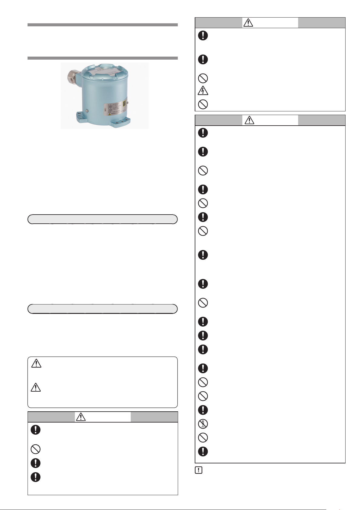
Intelligent Earthquake Sensor
Model SES70
User’s Manual
Thank you for purchasing this Azbil Corporation product.
This manual contains information for ensuring the safe and correct
use of the product. Also the manual provides necessary information
for installation, maintenance, and troubleshooting. It should be read
by those who design or maintain a control panel or other equipment
that uses this product. Be sure to keep the manual nearby for handy
reference.
For details refer to SES70 Intelligent Earthquake Sensor User’s Manual
for System Design, CP-SP-1376E.
Please read “Terms and Conditions” from the following URL before
ordering and use.
https://www.azbil.com/products/factory/order.html
NOTICE
Be sure that the user receives this manual before the product is used.
Copying or duplicating this user’s manual in part or in whole is forbidden. The information and specifications in this manual are subject to
change without notice.
Considerable effort has been made to ensure that this manual is free
from inaccuracies and omissions. If you should find an error or omission,
please contact the azbil Group.
In no event is Azbil Corporation liable to anyone for any indirect, special
or consequential damages as a result of using this product.
© 2015–2018 Azbil Corporation. All Rights Reserved.
Note: SES
™ is a trademark of Azbil Corporation.
SAFETY PRECAUTIONS
Safety precautions are for ensuring safe and correct use of this
product, and for preventing injury to the operator and other
people or damage to property. You must observe these safety
precautions. Also, be sure to read and understand the contents of
this user’s manual.
Key to symbols
WARNING
Warnings are indicated when mishandling this product might result in death or serious injury to the user.
CAUTION
Cautions are indicated when mishandling this product might result
in minor injury to the user, or only physical damage to this product.
WARNING
This device is certified as a pressure-resistant explosion-proof
construction (Ex d IIB T4). Install it in a location that complies with
this certification.
When there might be an explosive atmosphere do not open the
cover.
If you use the Smart Loader Package (sold separately), do so in a
non-hazardous area where there is no danger of explosion or fire.
Always use the cable gland and flameproof packing set supplied
with this unit. Use packing that is appropriate for the cable. If
the wrong packing is used the unit will no longer be a certified
explosion-proof product.
E1
WARNING
Use cables with a heat resistance of 80°C or more. If a cable with
a heat resistance of less than 80°C is used the unit will no longer
be a certified explosion-proof product. Moreover fire or device
failure may result.
After wiring work be sure to firmly tighten the cover screws.
Otherwise the unit will not satisfy the conditions for a pressureresistant explosion-proof construction.
In Taiwan, this device cannot be used in an explosive atmosphere.
Before doing wiring work be sure to disconnect the power. Failure
to do so may result in an electric shock.
If the cover is open in a hazardous area do not turn on the
electricity.
CAUTION
Only specialists with the proper knowledge and technical skill
concerning this type of equipment and this unit should carry
out the installation, wiring, inspection, and maintenance work.
This device does not incorporate any countermeasures against
lightning. As necessary, take appropriate measures to protect
equipment from lightning.
Do not use a walkie-talkie or other transceiver within 2 m of this
unit or cables connected to this unit. Doing so might cause this
unit to malfunction.
Use shielded cables for wiring.
Be sure to carry out the wiring work properly. Incorrect wiring
may cause device failure.
Take special care that crimp terminals (etc.) are not in contact
with adjacent terminals.
For control of critical equipment (e.g. for earthquake emergency shutdown), to avoid dependence on a single output use
this earthquake sensor together with another one, or use a
2-out-of-3 configuration.
If this unit malfunctions its electrical output may be incorrect.
If equipment safety might thereby be endangered, consider
having a fail-safe design for the system as a whole, with compartmentalization of controller and limits and with duplexing;
or use a redundant design.
Interference from a shock wave or electromagnetic wave may
activate the noise protection function of this unit preventing
vibration detection output or AO/DO output.
Do not subject this device to shock that exceeds the operating
conditions stated in the specifications. Doing do so may cause
device failure.
Handle the case and cover with care. If the threads are damaged, the cover will not open and close properly.
This device is a precision instrument. Impact from a 1cm fall is
enough to damage the internal sensor.
Be sure to handle it carefully. Take care to prevent impact when
removing this unit from the box, placing it on the floor temporarily during installation, etc.
During installation, take care not to bump this device against
metal objects such as pipes.
When connecting the wiring, be sure not to hit the sensor with a
crimping tool screwdriver or other tool.
When tightening the cable gland with a wrench, do not hit the
wrench with a hammer.
If there is a risk of impact to this unit after it is mounted install a
protective cover or like.
Do not disassemble or modify this device.
Do not subject this unit to impact or shock from a wrench or the
like when removing the unit for periodic inspection, etc.
When sending this unit back to Azbil Corporation for periodic
inspection, pack it in the shipping package specially made for it.
Contact the azbil Group for the shipping box.
Handling Precautions
•
Do not remove the seal from the cable gland connection
port until the wiring work is about to begin.
Page 2
UNPACKING
Flameproof
packing set
Cable gland
Adjustment hole for manufacturer
Along the Z axis, the direction of
positive direction.
The following items should be included in your purchase.
Product Qty. Notes
SES70 1
Flameproof packing set 1 for each cable diameter Flameproof packing (1) and washers (2) for 10–12mm outer diameter cable
Flameproof packing (1) and washers (2) for 12–14mm outer diameter cable
Cable gland set 1 Cable gland (1), cable clamp (1), lock nut (1)
Battery 1
Hexagon socket head setscrew 3 M6×10mm*
Cross-slot head screw with captive washer 3 for each length M5×30mm, M5×20mm
User's manuals 1 Manual No. CP-UM-5755
Handling notes 1 Manual No. CP-UM-5333E
*If the hexagon socket setscrews are used for level adjustment, use an M6 hex key.
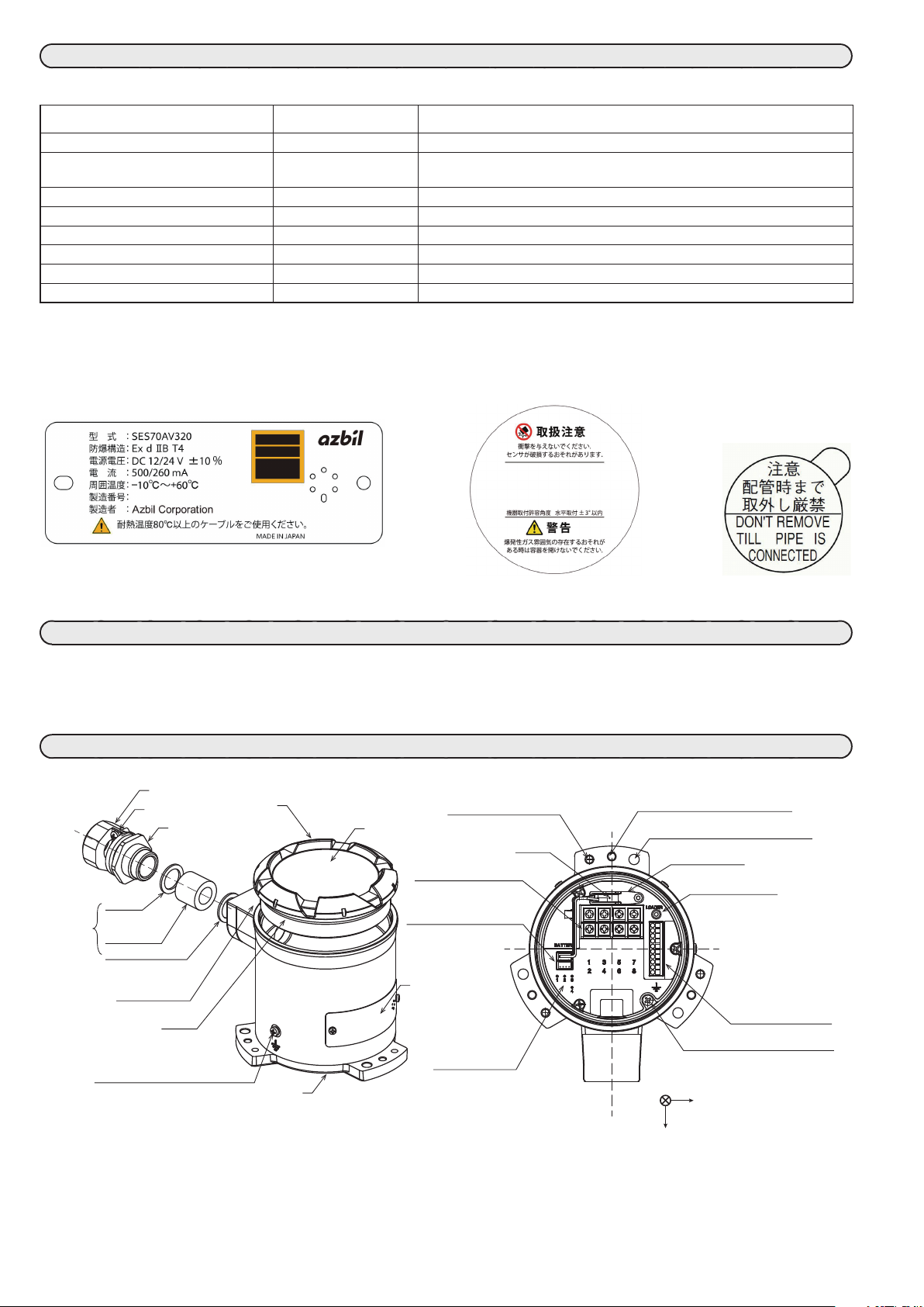
Nameplate, Label, and Seal
The following nameplate, label, and seal are attached to this unit.
Rating nameplate Warning label Seal
OVERVIEW
The Intelligent Earthquake Sensor calculates seismic intensity (SI), which represents estimated structural damage, and the Japan Meteorological
Agency (JMA) seismic intensity scale (shindo scale) equivalent value, based on acceleration signals generated from the built-in servo accelerometer.
Additionally, the unit judges ground liquefaction from the acceleration waveform characteristics and outputs the results.
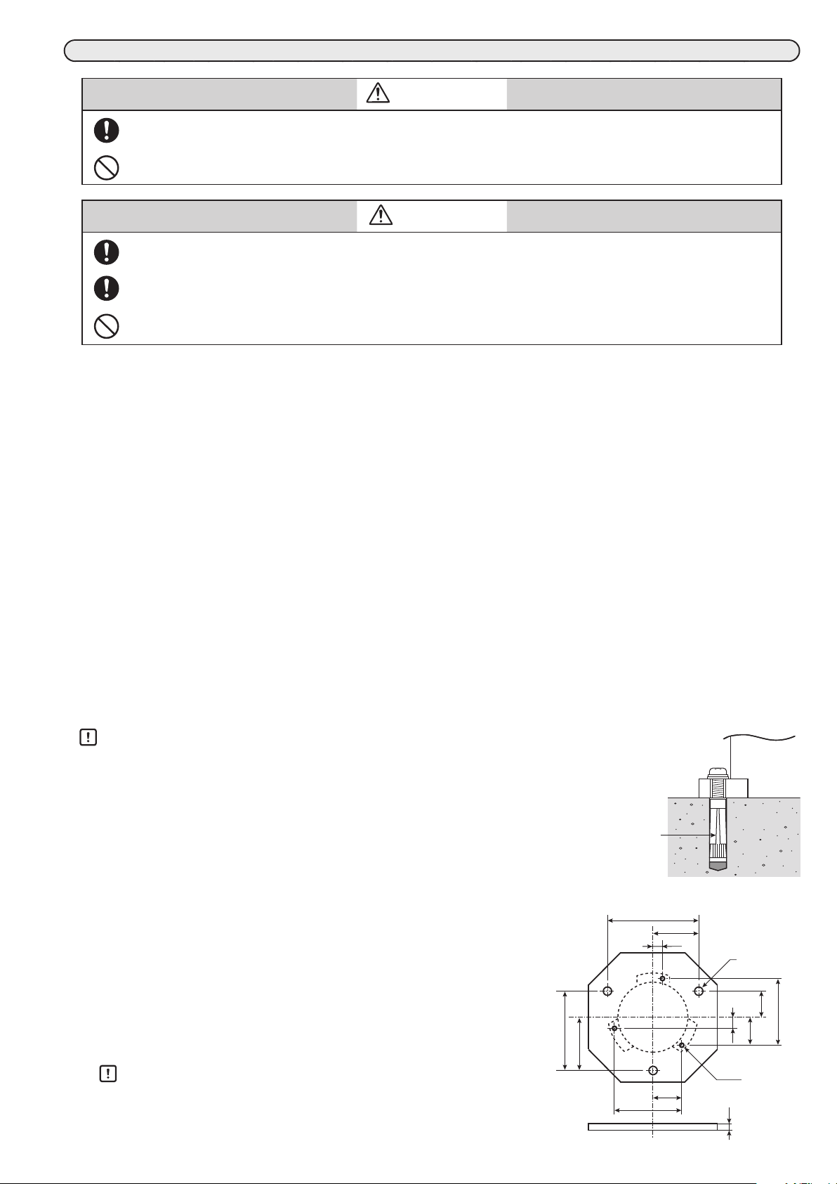
NAMES OF PARTS
Cable clamp
Lock nut
Washer
Flameproof
packing
Washer
Reference plane
O-ring
Ground terminal outside the case
(For cable connections,
use ring crimp terminals suitable
for cables whose cross-sectional
area is 4 mm
2
or larger.)
Cover
Level adjustment
M6 screw hole (3 places)
Warning label
Battery
Screw terminal block
(M3.5, 8terminals)
Battery connector (2 places)
Rating nameplate
Status display LEDs
LEDs 1 to 3: red
LED 4: green
Case
use only (3 places)
φ7 device mounting hole (3 places)
Battery holder
Loader jack socket
Spring terminal block
(10 terminals)
Ground terminal inside the case
Z
X
Acceleration measurement axes
Y
the earth's gravitation is the
E2
Page 3
INSTALLATION
W ARNING
This device is certified as a pressure-resistant explosion-proof construction (Ex d IIB T4). Install it in a location that
complies with this certification.
In Taiwan, this device cannot be used in an explosive atmosphere.
CAUTION
During installation or maintenance work, take care not to drop the unit accidentally to prevent injury to feet etc.
This device does not incorporate any countermeasures against lightning.
As necessary, take appropriate measures to protect equipment from lightning.
Do not subject this device to shock that exceeds the operating conditions stated in the specifications.
Doing do so may cause device failure.
Installation Location
Avoid installing the device where it will be subject to conditions such as the following.
•
Ambient temperature below −10°C or above +60°C
•
Humidity higher than 90%RH
•
Sudden temperature fluctuations causing condensation
•
Corrosive or combustible gas
•
Large amounts of conductive substances (e.g., dust, salt, or iron powder) or organic solvents
•
Direct shock or vibration other than earthquake motion
•
Direct sunlight
•
Large amounts of water or rain
•
Splashing by fluids (e.g., oil or chemicals)
•
Strong magnetic or electrical fields
Installation Instructions
This unit measures ground acceleration caused by earthquake motion in order to calculate the estimated amount of damage.
Installation of this unit on a concrete foundation separated from buildings is recommended so that building vibration does not affect measurement.
In addition, where needed to prevent direct exposure to sunlight or rain, provide a protective roof or cover.
Handling Precautions
•
Do not use the three adjustment holes (which are for manufacturer use only) when installing
the unit.
•
When installing the unit on a concrete foundation, check that the foundation is not hollow by
tapping it with a small hammer.
When installing this unit, select one of the methods shown below depending on the installation
conditions.
If the installation surface is level within ±3°
(1) Select a flat concrete surface for installation.
(2) Put three anchors or plug bolts in the surface, aligned with the three 7mm
mounting holes in the unit.
(3) Attach the unit with the three mounting screws (M5×30mm).
If the installation surface is not level
(1) Get a metal plate (10mm thick or more) with three holes for level adjustment
and three threaded M5 holes for attaching the unit.
The dimensions of the mounting plate are shown on the right.
Anchor
(bolt plug)
142
71
15
123
82
Sensor unit
Concrete
Unit: mm
φ13 (3 places)
41
43
17
103
Handling Precautions
•
If the mounting plate is attached to a concrete surface, use M10 or larger
anchors. The diameter of the corresponding holes in the plate is 13mm.
(2) Put three anchors in the concrete surface for attaching the mounting plate.
E3
104
44.5
M5 (3 places)
10
Page 4

(3) Attach the mounting plate to the anchors as shown in the figure on the right.
Mounting plate
M5
M10
Upper nut
Lower nut
Anchor
socket setscrew
M5 retaining
(4) Adjust the three lower nuts so that the mounting plate is level.
(5) Tighten the upper nuts to secure the plate.
Handling Precautions
•
Tighten the three upper nuts evenly so that the plate remains level.
•
After the mounting plate has been installed, make sure that it is level within ±2°.
(6) Temporarily tighten the mounting screws (M5×20mm) included with the unit.
(7) Check that the unit is level.
(8) Make fine adjustments of the M6 hexagon socket setscrews so that the unit is level.
(9) Tighten the three mounting screws (M5×20mm), which were previously tightened tem-
porarily to secure the unit.
What to check after installation
Place a level on the reference plane of this unit to check that the unit is level within ±3°.
If the unit is not installed correctly, malfunction could result.
WIRING
W ARNING
screw
Sensor unit
Concrete
Sensor unit
M6 hexagon
Mounting plate
Use cables with a heat resistance to temperatures of 80°C or more. If a cable with a heat resistance of less than 80°C
used, the unit will no longer be a certified explosion-proof product. Moreover, fire or device failure may result.
Always use the cable gland and flameproof packing set supplied with this unit. In addition, use packing that is appropriate for the cable. If the wrong packing is used, the unit will no longer be a certified explosion-proof product.
Before doing wiring work, be sure to disconnect the power. Failure to do so may result in an electric shock.
During installation, trial runs, and maintenance work, do not touch the power terminals. There is a risk of electric
shock.
During installation, trial runs, and maintenance, work if the unit malfunctions immediately disconnect the power.
If the cover is open in a hazardous area do not turn on the electricity.
When there might be an explosive atmosphere do not open the cover.
If you use the Smart Loader Package (sold separately), do so in a non-hazardous area where there is no danger of
explosion or fire.
CAUTION
Use shielded cables for wiring.
Be sure to carry out the wiring work properly. Incorrect wiring may cause device failure. Particularly, do not mistakenly connect the DO to the RS-485 terminal.
The power and signal lines must be isolated from the ground. Otherwise, noise could cause malfunction or device
failure.
Take special care that crimp terminals (etc.) are not in contact with adjacent terminals. Failure to do so may cause
fire or device failure.
Be sure to use bootlace ferrules when wiring the spring terminal block.
Do not use a walkie-talkie or other transceiver within 2 m of this unit or cables connected to this unit. Doing so may
cause this unit to malfunction.
Take care not to damage the threads on the case or cover. If the threads are damaged, the cover will not open and
close properly.
E4
Page 5

Wiring Procedure
The cable lead-in system of this unit uses flameproof packing. The compatible
cable outer diameter is 10 to 14mm. The following flameproof packing sets
are included with this unit.
• Flameproof packing set for 10 to 12mm outer diameter cable
• Flameproof packing set for 12 to 14mm outer diameter cable
(1) Loosen the setscrew to open the cover.
(2) Insert the cable into the unit as shown in the figure on the right, and con-
Cable gland connection port
Flameproof packing
Lock nut
Cable clamp
Washer
Washer
Clamp tightening screw
Cable gland
Cable
Flameproof
packing set
nect the cable to the terminal block.
(3) Screw in the cable gland so that the amount of compression corresponds to the cable diameter as specified in the “Cable outer diameter
and amount of packing compression” table below.
(4) Tighten the lock nut.
(5) Secure the cable using the cable clamp.(Tightening torque: 0.6Nm)
(6) Connect the battery cable included with this unit to the battery connector and insert the battery into the battery holder. The cable can be
connected to either battery connector.
Note
•
The table below shows the proper amount of packing compression for various cable diameters. The appropriate amount of packing compression varies depending on the cable diameter and the packing inner diameter. Measure the outer diameter of the cable and choose the
most appropriate amount of compression for the cable from the table below. The amount of compression can also be adjusted by the number of screw rotations. In the table, counting of the number of screw rotations begins when the cable gland contacts the packing.
Cable outer diameter and amount of packing compression Packing compression (left: before, right: after)
Cable outer
diameter (mm)
φ 10.0 min. 12 3.9 2.1
φ10.5 3.5 1.9
φ11.0 3.1 1.7
φ11.5 2.7 1.5
Less than φ 12.0 2.2 1.2
φ 12.0 min. 14 4.5 2.5
φ12.5 4.0 2.2
φ13.0 3.5 1.9
φ13.5 2.9 1.6
φ14.0 2.3 1.3
Packing inner
diameter (mm)
Packing compres-
sion (mm)
No. of screw
rotations
Before tightening
(A) (B)
Cable gland
Packing
Clamp tightening screw
Tighten the clamp tightening screws to a maximum torque of 0.6 N.m.
After tightening
Length A-B = Amount of compression of packing
Wiring diagram
0.5
Note:
•
Terminal SG (for RS-485) is connected to terminal 2 in the terminal
block inside the unit.
•
Do not connect the DO to the RS-485 terminals.
Screw terminal block
Terminal No. Signal
1 Power (+) (12/24 V DC)
2 Power (−) (0 V DC)
3, 4 Relay contact output 1 (vibration detection output 1)
5, 6 Relay contact output 2 (vibration detection output 2)
7, 8 Relay contact output 3 (vibration detection output 3)
Spring terminal block
Terminal No. Signal
9 Analog output 1: 4-20mA ([synthesized AC acceleration],
SI value, JMA seismic intensity scale equivalent value)
10 Analog output 2: 4-20mA (synthesized AC acceleration,
[SI value], the JMA seismic intensity scale equivalent value)
11 Digital output 1 (minor failure output*
12 Digital output 2 (serious failure output*
13 Digital output 3 (noise protection output, [positive logic],
14 Digital output 4 (liquefaction detection output)
15 Digital input (transition request to maintenance mode/
16 RS-485 DA
17 RS-485 DB
18 RS-485 SG
Note: The default setting is enclosed in brackets, [ ].
*1. A minor failure does not affect control output but a check should be
made for waveform record and clock data storage errors, as well as
clock data errors. The installation conditions should also be checked.
While LED 4 (green) is lit, LED 1 (red) is lit and digital output 1 (DO1)
turns ON. In any mode other than measurement mode, DO1 repeatedly turns ON and OFF. In addition, by changing the setting, it can be
made to turn ON only when a minor failure occurs.
*2. A serious failure may affect control output such as vibration detection
output and liquefaction detection output.
While LED 4 (green) is lit, LED 2 (red) is lit.
Then digital output 1 (DO1) turns ON.
Note that when a serious failure occurs, minor failure output (DO1) is
also generated.
E5
[positive logic], negative logic)
negative logic)
negative logic)
standby mode and diagnostic phase change request in
the maintenance sequence)
1
/mode display,
2
, [positivelogic],
Page 6

Handling Precautions
: Voltage-limiting element.
SES70
SurgeNon
•
Keep wiring away from cables connected to a commercial power supply or motor drive power supply that is likely to produce electrical
noise.
•
If this unit is used alone, its miswiring protection is effective. However if multiple units are connected through RS-485, miswiring of the
power source may cause device failure. Be sure to check that the wiring is correct before turning the power on.
•
For screw terminal connections, use crimp terminals that are the correct size for M3.5 screws.
•
For spring screw terminal connections, use wires whose nominal cross-sectional area is 0.25 to 0.75 mm2 (24 to 18 AWG), with bootlace
ferrules. Use bootlace ferrules and a crimping tool that comply with the following standards.
Do not insert stripped or soldered ends of stranded wires into the spring terminal block.
Bootlace ferrule: DIN 46228 sect. 4
Crimping tool: DIN 46228 parts 1 and 4
The compatible bootlace ferrules and crimping tool made by
Weidmuller Japan Co., Ltd. are shown on the right.
•
To connect a wire to the spring terminal block, insert a bootlace ferrule into the hole (push-in system).
•
To remove a wire from the spring terminal block, push the button on the block using a flat-head screwdriver (tip size: 0.4×2.5 mm) and
pull out the wire. The standard pushing force on the button and the pushed distance are 20 N and 1.7 mm respectively. If the pushing
force on the button is 40 N or greater, device failure could result.
•
For wiring for RS-485, do not connect an external terminating resistor.
•
For wiring, follow the wiring diagram.
•
Use shielded cables. Use a shielded cable to wire the ground terminal inside the case.
•
Use either of the following methods so that there is only one ground connection.
(1) Ground the other end of the shielded cable that is connected to the ground terminal inside the case.
(2) Ground the ground terminal that is outside the case.
The ground connection should have a resistance of 100 Ω or less.
•
If the battery included with this unit is not used, the clock data and recorded waveform data will not be backed up while power is not
being supplied. In this case, the unit will have a minor failure status.
•
If the battery is not connected to the unit or if the clock is not set, the unit will have a minor failure status.
•
If the removed battery is connected to the unit again, the unit may
take time to recognize the battery. Until it is recognized, the unit
will have a minor failure status.
•
If there is a risk of power surge caused by lightning, use Azbil
Corporation’s FA SurgeNon surge protector (QN430C series).
Make the wiring between the unit and the SurgeNon as short as
possible.
Compatible bootlace ferrules made by Weidmuller Japan
2
Connectable wire (mm
0.25 10 H0.25/12
0.34 H0.34/12
0.50 H0.5/14
0.75 H0.75/14
The manufacturer's compatible crimping tool: PZ 6 Roto
) Stripped wire length (mm) Part No.
Signal +
Signal −
FG
• Power source
• RS-485 host device
• Control devices (DO, DI, AO)
BEFORE USE
W ARNING
If you use the Smart Loader Package (SLP-SE7, sold separately), do so in a non-hazardous area where there is no
danger of explosion or fire.
Set the time using the SLP-SE7 Smart Loader Package (sold separately).
(1) While the power is not being supplied to the unit, open the cover and connect the loader.
(2) Turn on the power to the unit and wait for LED 4 (green) to be lit.
(3) Set the time on the unit’s built-in clock using the loader.
(4) Wait for LED 4 to be lit.
(5) Make sure that only LED 4 is lit (normal operation).
Handling Precautions
•
If another LED (red) is lit, an error has occurred. Take corrective action following the user’s manual for the loader.
(6) Make sure that the unit is working properly, and then turn off the power and disconnect the loader.
(7) Firmly tighten the cover until its flange tightly contacts the top edge of the case.
(8) Turn on the power. About 60 seconds later, the unit will be ready to measure seismic waves.
SLP-SE7 Smart Loader Package for SES70 Intelligent Earthquake Sensor (CP-SP-1394E)
Handling Precautions
•
If the time has not been set, the clock will start at 00:00 on January 1, 2050, and the unit will have a minor failure status.
•
When tightening the cover, take care to prevent cables from being caught.
E6
Page 7

MAINTENANCE AND TROUBLESHOOTING
W ARNING
When there might be an explosive atmosphere do not open the cover.
When discarding the battery, do not throw it into the fire. Doing so may cause it to explode.
Maintenance
Check the following regularly:
•
The case, cover, and cable gland are not damaged.
•
The cable gland and cover are not loose.
•
The terminal screws are not loose.
•
The O-ring attached to the cover is not damaged.
•
The reference plane is level within ±3°.
Specifications
Item Description
Basic
specifications
Electrical
specifications
Explosion-proof standard Ex d IIB T4 (TIIS pressure-resistant explosion-proof construction)
Rated acceleration range ±2000 Gal (in x, y, and z axis)
Acceleration measurement range ±2200 Gal (in x, y, and z axis)
Acceleration measurement
resolution
FSG sensitivity ±2 % FSG (±980 Gal)*
FSG middle point ±3 % FSG*
Measurement accuracy ±2 % of measured value (at 0 to 50 °C, at 100 Gal span min., in DC measurement)*
Output linearity ±2 % FSO (+2000 Gal) ± 2 % FSO (−2000 Gal)*
Sensitivity in other axial axis ±3 % in x, y, and z axis
Electrical noise 2 Gal (acceleration filter: 30 Hz) in x, y, and z axis
Acceleration sampling 10 ms sampling
Acceleration waveform recording 10 ms sampling for 360 s, waveforms in x, y, and z axis, 10 waveforms
Analog output accuracy ±0.2 % FS
Rated voltage 12 V DC ±10 % or 24 V DC ±10 %
Current consumption 500/260 mA (12/24 V DC)
Power ON inrush current 30 A/500 μs max.
Contact output (vibration detection
outputs 1 to 3)
Digital output 1 (minor failure de-
tection output)
Digital output 2 (serious failure de-
tection output)
Digital output 3 (noise protection
output)
Digital output 4 (liquefaction
output)
Analog output 1 4-20 mA current source (default setting: synthesized AC acceleration = 0 to 2000 Gal)*
Analog output2 4-20 mA current source (default setting: SI value = 0 to 200 kine)*
Analog output load resistance 300 Ω max.
Digital input (diagnostic input) Photocoupler input current source, 9 mA max.
Communication Loader communication: TTL, 115200 bps
Dielectric strength 500 V AC for 1 min or 600 V AC for 1 s
Insulation resistance 100 MΩ with 500 V DC megger
Troubleshooting
If this unit does not work or malfunctions, check the following:
•
Is the wiring loose or disconnected?
•
Are the supply power and load resistance correct?
•
Is faulty output being generated?
•
Also check the following using the loader (sold separately):
•
Is the acceleration or SI value abnormal?
•
Is an internal error displayed on the detailed error screen?
•
Is manual output selected?
•
SES70 Intelligent Earthquake Sensor User’s Manual For
System Design (CP-SP-1376E)
Model selection
•
Standard model SES70AV320-1110
•
With inspection report SES70AV320-111D
•
Inspection report+traceability certificate SES70AV320-111Y
SPECIFICATIONS
1 Gal (at static acceleration)
1
1
in x, y, and z axis
±2 Gal (at 0 to 50 °C, at less than 100 Gal span, in DC measurement) in x, y, and z axis
Relay 1a, 30 V DC, 0.5 A max.
Transistor output (Nch open drain), 30 V DC, 50 mA max. (default setting: ON in case of a minor failure,
ON/OFF action in any mode other than measurement mode)
Transistor output (Nch open drain), 30 V DC, 50 mA max. (default setting: ON in case of a serious failure)
Transistor output (Nch open drain), 30 V DC, 50 mA max. (default setting: ON when noise protection
detection is ON)
Transistor output (Nch open drain), 30 V DC, 50 mA max. (default setting: ON when liquefaction is
detected)
RS-485 communication: 3-wire system, 38400/19200/9600 bps (default setting: 38400 bps)
in x, y, and z axis
1
in x, y, and z axis
1
,
2
2
E7
Page 8

Item Description
Mechanical
specifications
Material Case and cover: aluminum alloy casting
Mounting angle Within ±3° from horizontal
Cable gland type G3/4 flameproof packing
Mass 1.9 kg
Environmental
specifications
Operating ambient temperature −10 to +60 °C (without freezing)
Guaranteed accuracy ambient
0 to +50 °C (without freezing)
temperature
Storage temperature −20 to +70 °C
Operating humidity 90 %RH max. (without condensation)
Waterproofing and dust-proofing IP67 (1 m under water for 30 min), JIS C0920 watertight (unless conduit is used without cable gland)*
Vibration resistance 19.6 m/s2 max.
2
Shock resistance 490 m/s
max.
Accessories 2 sets of flameproof packing (different types)
Flameproof packing (1) and washers (2) for 10 to 12 mm outer diameter cable
Flameproof packing (1) and washers (2) for 12 to 14 mm outer diameter cable
Cable gland set (cable gland, cable clamp, lock nut)
Battery (life: 10 years min. when power is supplied 6 months when no power is supplied, at 20 °C)
3 hexagon socket bolts (M6×10 mm)
Cross-slot head screws with captive washer (3 each of M5×30 mm and M5×20 mm)
User's manual, No. CP-SP-1393E
Accessories (sold separately) SLP-SE7 Smart Loader Package for SES70 Intelligent Earthquake Sensor
Replacement
parts
Replacement battery Part No. 81446431-001
Manufacturer: Azbil Corporation
Electrochemical: Manganese dioxide lithium battery
Nominal voltage: 3 V
Rated capacity: 240 mAh
Maintenance parts set for SES70 Part No. 81447670-001
Manufacturer: Azbil Corporation
Includes: a cable gland and an O-ring
*1. Measurement conditions
•
Supply voltage: 12 or 24 V DC ±10%
•
Ambient temperature: 0 to 50°C
•
Humidity: 50 ±20%RH
*2. Output of synthesized AC acceleration, SI value, or JMA seismic inten-
sity scale equivalent value can be selected.
*3. Waterproofing and dust-proofing are not tested by TIIS.
% FSG: percentage of the 1960 Gal span
% FSO: percentage of the 4000 Gal span
3
External dimensions Unit: mm
(44)
43
59.559.57544.544.5
Flameproof packing
Cable gland
G3/4
M4 ground terminal outside the case
(69)89
60
17
15
15
Level adjustment M6 screw holes (3)
3×R 69
50
φ7 unit mounting holes (3)
DISPOSAL
When discarding this device dispose of it properly as industrial
waste, following local regulations.
Dispose of used batteries appropriately according to local regulations.
109
122.5
1-12-2 Kawana, Fujisawa
Kanagawa 251-8522 Japan
: https://www.azbil.com
URL
E8
Specications are subject to change without notice.
1st edition: Feb. 2015 (V)
3rd edition: Dec. 2018 (M)
(10)
 Loading...