

Page 1
CP-UM-5445JE
デジタル指示調節計
SDC45/46
取扱説明書 設置編
このたびは当社製品をご購入いただき、まことにありがとうございま
す。この取扱説明書には、製品を安全に正しくご使用いただくための
必要事項が記載されております。また、この取扱説明書は、取り付け
時だけでなく、保守、トラブル時の対応などの際に必要です。当社製
品を使用した操作盤、装置の設計、保守を担当される方は、必ずお読
みになり、理解したうえでご使用ください。いつもお手元においてご
活用ください。
ご注文・ご使用に際しては、下記URLより「ご注文・ご使用に際して
のご承諾事項」を必ずお読みください。
http://www.azbil.com/jp/product/factory/order.html
お願い
この取扱説明書は、本製品をお使いになる担当者のお手元に確実に届
くようにお取りはからいください。
この取扱説明書の全部、または一部を無断で複写、または転載するこ
とを禁じます。この取扱説明書の内容を将来予告なしに変更すること
があります。
この取扱説明書の内容については、万全を期しておりますが、万一ご
不審な点や記入もれなどがありましたら、当社までご連絡ください。
お客さまが運用された結果につきましては、責任を負いかねる場合が
ございますので、ご了承ください。
© 2007–2018 Azbil Corporation All Rights Reserved.
● 機器の定格
AC電源モデル
供給電圧 AC100 ~240V(動作電源電圧AC85~264V)
電源周波数 50/60Hz
消費電力 30VA以下(SDC45)、40VA 以下(SDC46)
DC電源モデル
供給電圧 DC24V(動作電源電圧 DC21.6 ~ 26.4V)
消費電力 12W以下(SDC45)、15W 以下(SDC46)
● 環境条件
可燃性の液体や蒸気のあるところでは使用しないでください。
そのような環境下で使用すると安全性を損ないます。
使用温度範囲 0 ~ 50℃
使用湿度範囲 10 ~ 90%RH(結露なきこと)
許容振動 2m/s
過電圧カテゴリ CategoryⅡ(IEC60364-4-443、IEC60664-1)
汚染度 2
設置場所 屋 内
高 度 2000m以下
一時的過電圧 電源電圧+250V
● 機器の設置
計器を操作される方が計器の背面端子に触らないように、この製品
は必ずパネルに取り付けてください。供給電源およびリレー接点出
力を除く入出力のコモンモード電圧:対大地間の電圧は、
30V rms以下、42.4Vピーク以下、DC60V以下としてください。
● 適合規格
EN61010-1、EN61326-1(For use in industrial locations)
EMC試験中、±10%FSに相当する指示値や出力値の変動が生じ
る場合があります。
2
(10 ~ 60Hz)
関連取扱説明書
本書は使用上の注意事項と取り付け・結線・PVレンジ種類・主な仕様
などを説明したものです。詳しい取扱方法・設定方法などは、別冊の「詳
細編」および「表示・設定データ一覧」をご覧ください。
各種機能の操作については次の説明書があります。
必要に応じてお読みください。
SDC45/46 表示・設定データ一覧 CP-UM-5457
SDC45/46 詳細編 CP-SP-1218
SDC45V/46V 演算機能編 CP-SP-1275
スマートローダパッケージSLP-C45 CP-UM-5458
これらの資料は http://www.compoclub.com からダウンロードするこ
ともできます。
確認してください
お買い上げいただいたSDC45/46は次のものが同梱されています。
万一、異常や間違いがあった場合は、直ちにお買い上げの販売店までご
連絡ください。
取付器具 81405411-004 2個
ガスケット (SDC45用) 81421863-001 1個
(SDC46用) 81421864-001 1個
取扱説明書(本書) CP-UM-5445JE 1部
表示・設定データ一覧 CP-UM-5457 1部
安全要求事項(SAFETY REQUIREMENT)
人に損傷を与えるような感電の危険を減ずるために、この取扱説明書
に記載されているすべての安全に関わる注意事項に従ってください。
このシンボルは、触ると感電のおそれがあることをお客様に警告する
ものです。
• 当社が規定しない使い方をした場合、この製品に盛り込まれた安全保
護は損なわれます。
• 当社によって決められた以外の部品に交換しないでください。
• すべての配線作業は、それぞれの地域での規則に従って、認定されか
つ経験のある作業者によって行われなければなりません。
• 計器を操作される方がとどく範囲内に、この製品の主電源遮断用のス
イッチを必ず設けてください。
• AC電源モデルの主電源配線には、遅動タイプ(T)の、定格電流 1.0A、
定格電圧250Vのヒューズを設けてください。ヒューズは非接地側の
配線に設けてください。(IEC127)
• DC電源モデルの主電源に接続するDC電源装置には、クラスⅡの電
源装置を使用してください。
安全上の注意
この安全上の注意は、製品を安全に正しくお使いいただき、あなたや
他の人々への危害や財産への損害を未然に防止するためのものです。
安全上の注意は必ず守ってください。また、内容をよく理解してから
本文をお読みください。
● 警告表示の意味
警告
注意
取り扱いを誤った場合に、使用者が死亡または重傷
を負う危険の状態が生じることが想定される場合。
取り扱いを誤った場合に、使用者が軽傷を負うか、
または物的損害のみが発生する危険の状態が生じる
ことが想定される場合。
警告
FG端子をD種接地以上に確実に接続してから、測定対象や外部
制御回路への接続を行ってください。
本器への通電前に配線が正しく行われていることを確認してく
ださい。本器への配線間違いは故障の原因になり、また危険な
災害を招く原因にもなります。
本器の取り付け、取り外し、および結線のときは、本器および
接続機器の電源をすべて切ってください。
感電することがあります。
電源端子などの充電部には触らないでください。
感電のおそれがあります。
本器を分解しないでください。
感電・故障のおそれがあります。
注意
本器は、仕様に記載された使用条件(温度、湿度、電圧、振動、衝撃、
取付方向、雰囲気など)の範囲内で使用してください。
火災、故障のおそれがあります。
本器への結線は定められた基準に従い、指定された電源、およ
び施工方法で正しく配線してください。
火災、感電、故障のおそれがあります。
本器ケース内部に線くず、切粉、水などが入らないようにして
ください。火災、故障のおそれがあります。
端子ねじは仕様に記載されたトルクで確実に締め付けてくださ
い。締め付けが不完全だと感電、火災のおそれがあります。
本器の未使用端子を中継端子として使用しないでください。
火災、感電、故障のおそれがあります。
J1
Page 2
注意
48
96
11
130
43.8
96
96
11
130
91.4
50
92
+0.5
(48×N−4)
+0.5
50
92
+0.5
(96×N−4)
+0.5
本器の結線後は端子カバーを取り付けることをお勧めします。感
電のおそれがあります。(
本器のリレーは仕様に記載された寿命の範囲内で使用してくだ
さい。範囲を超えて使い続けると火災、故障のおそれがあります。
雷サージのおそれがある場合には、サージアブソーバ(サージ防
止器)を使用してください。火災、故障のおそれがあります。
本器の通風穴をふさがないでください。
火災、故障のおそれがあります。
キー操作の際には先のとがったもの(シャープペンシルの先や針
など)で押さないでください。故障の原因となります。
本器は電源投入後、設定により2 〜 60秒間は動作しません。
調節計からのリレー出力も同様に動作しないので、使用する場
合には注意してください。
取り外したバッテリは各自治体の条例、または規則に従って適
切に廃棄ください。
使用するセンサ種類にあった正しい設定をしてください。誤っ
た設定では正常なPV値を測定できないため、制御出力が100%
になるなど、危険な状態になる場合があります。
本器は別売品の端子カバーを用意しています
)
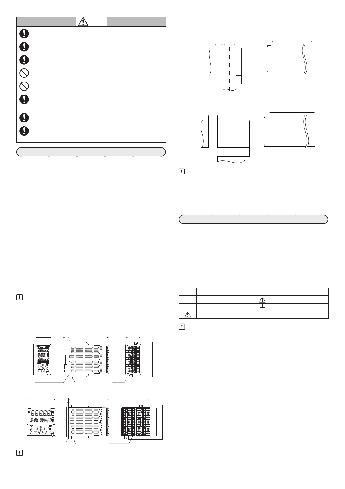
■ パネル穴あけ図
● SDC45
個別取付 密着取付(SDC45R を除く)
以上
● SDC46
個別取付 密着取付(SDC46R を除く)
以上
単位:mm
+0.5
44
0
+0.5
0
92
50
以上
+0.5
92
0
+0.5
0
92
0
0
0
0
設 置
■ 取付場所
本器を取り付けるときは、次のようなところに設置してください。
• 供給電源およびリレー接点出力を除く入出力のコモンモード電圧:
対大地間の電圧は、30V rms以下、42.4Vピーク以下、DC60V以下
としてください。
• 高温、低温、高湿度、低湿度にならないところ
• 硫化ガスなど腐食性ガスのないところ
• 粉じん、油煙などの少ないところ
• 直射日光および風雨の当たらないように適切な処理のされたところ
• 機械的振動、衝撃の少ないところ
• 高圧線の下、溶接機の近くおよび電気的ノイズの発生源の近くでな
いところ
• ボイラなどのような高圧点火装置から15m 以上離れたところ
• 電磁界の影響の少ないところ
• 可燃性の液体や蒸気のないところ
• 屋 内
■ 取付方法
• 取付角度は水平位置から、後下がり10 度以内、後上がり 10 度以内
としてください。
• パネルは板厚7mm 以下(ガスケット使用時は 5mm 以下)で剛性のあ
るものをご使用ください。
取り扱い上の注意
• 防水用として使用する場合は、必ず本体にガスケットを取り付けて
ください。
■ 外形寸法
● SDC45
2
端 子 ねじ
M3
端子ねじM3
ガスケット(付属品)
取付器具(付属品)
● SDC46
2
ガスケット(付属品)
取り扱い上の注意
取付器具(付属品)
• 付属の取付器具のねじを締めて、取付器具が動かなくなったガタの
ない状態で、さらに1回転だけねじを回してパネルに固定してくだ
さい。ねじを締めすぎるとケースが変形してしまいます。
単位:mm
91.4
110
91.4
50
以上
取り扱い上の注意
防水・防じん用として使用する場合は、必ず個別取付にしてください。
•
• SDC45R/46Rは必ず個別取付にしてください。
• 3台以上の密着で取り付ける場合は、周囲温度は 40℃を超えない
ようにしてください。
• 上下方向は50mm 以上の間隔を空けてください。
結 線
本器を操作される方の手が届く範囲内に、本器の主電源遮断用のスイッ
チを必ず設けてください。また、AC電源モデルの本器の電源配線には遅
動タイプ(T)の定格電流 1.0A、定格電圧 250V のヒューズを設けてくださ
い。スイッチとヒューズは非接地側の配線に設けてください。(IEC127)
UL規格対応のためには、下記ヒューズをご使用ください。
メーカー: LITTELFUSE INC.
型 番 : Type 215001 または Type 477001
定 格 : AC250V、1A
本器側面の端子配列ラベルで使用している記号の意味は下表のとおりです。
記号 内 容 記号 内 容
110
〜 交 流
直 流 機能接地端子(保護接地端
注意、感電の危険
取り扱い上の注意
• 結線は形番と端子番号を本体側面のラベルで確認してから行い、必
ず間違いのないことを確認してください。
•
端子の接続にはM3のねじに適合する圧着端子を使用してください。
• 一つの端子ねじに複数の圧着端子を配線する場合は、あらかじめ圧
着端子を曲げ、2枚までの接続としてください。
• 入出力信号線は動力線や電源線から50cm 以上離してください。
また、同一の配線管やダクト内を通さないでください。
• 圧着端子などが隣の端子と接触しないようにしてください。
• 本器に接続する機器または装置は、本器の電源、入出力部の最高使
用電圧に適した強化絶縁または2重絶縁が施されているものを使用
してください。
• 本器は電源投入後安定のため、設定により2 〜 60秒間は機能しな
いようになっています。その後運転状態に入りますが、規定の精度
を満足させるためには、ウォームアップ時間が30分以上必要です。
• カレントトランスにはヒータ電流の流れる導線を貫通させてくださ
い。また、ヒータ電流は仕様に記載した許容電流を超えて使用しな
いでください。本器を破損することがあります。
• カレントトランス入力は位相制御に使用できません。
• モータ駆動端子とMFB 入力端子は、同一ダクト内に配線したり、6
心ケーブルで配線しないでください。モータ起動時のノイズなどで
本器の故障の原因になります。
J2
注 意
子ではありません)
Page 3
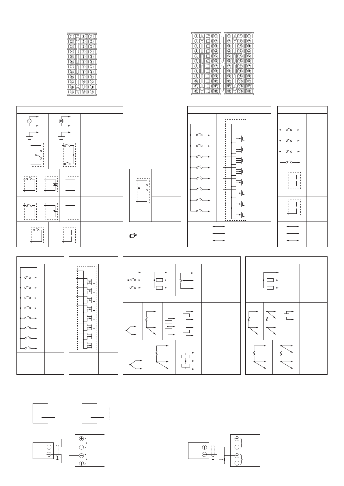
■ 結 線
①
①
①
①
④
④
⑦
⑦
⑦
⑦
⑥
⑨
⑨
⑨
⑧
⑪
⑪
⑩DA
⑩DA
①
①
①
①
Y
①
⑤
⑤
A
⑤
⑤
+
⑤
A
⑤
A
⑤
+
⑨
⑨
A
⑨
⑨
A
A
⑨
● SDC45背面
A
C F
A(SDC45/46 共通) C(SDC45 共通) C(SDC46 共通)
内 容 内 容 内 容
(1)
(1)
⑤
⑥
(1)
⑧
(1)
⑩
(1)
⑫
②
③
1
2
(2)
⑧
(2)
⑩
(2)
(2)
(2)
⑤
⑥
(3)
⑧
(3)
⑩
⑫
電 源
•
(1) AC 電源
②
③
1
2
+
−
AC100 〜 240V
(2) DC 電源
DC24V(無極性)
出力1、出力2
•
(OUT1/OUT2)
(1) リレー(1a1b)
(2) リレー(1a)
出力3(OUT3)
•
(1) リレー
+
(2) トライアック
−
(3) 電流、電圧パルス、
連続電圧
出力4(OUT4)
•
(1) リレー
+
(2) トライアック
−
(3) 電流、電圧パルス
出力5(OUT5)
•
(1) リレー
(2) 電流、連続電圧、
発信器用電源
A(SDC46モータ駆動
リレーモデル)
(1)
⑧
⑩
モータ駆動リレーモデルの
結線の詳細は、
D(SDC46 共通) E(SDC46共通) F(SDC45A/46A/45V/46V) F(SDC45R/46R)
内 容 内 容 内 容 内 容
D1
②
D2
③
D3
④
D4
⑤
D5
⑥
D6
⑦
D7
⑧
D8
⑨
— 未使用
⑩
—
⑪
—
⑫
デジタル
•
入力
(DI)
①
②
③
④
⑤
⑥
⑦
⑧
⑨
COM(−)
E1
E2
E3
E4
E5
E6
E7
E8
⑩
⑪
⑫
— 未使用
—
—
デジタル
•
出力
(DO)
(1)
(1)
(1)
⑥
−
⑦
+
⑧
*(4)は SDC45V/46V 3 入力モデルだけ
● 発信器用電源の端子番号
出力5 出力7(SDC46 だけ)
A列
⑪
⑫
+
ー
C列
⑧
⑨
注)発信 器用電源
+
ー
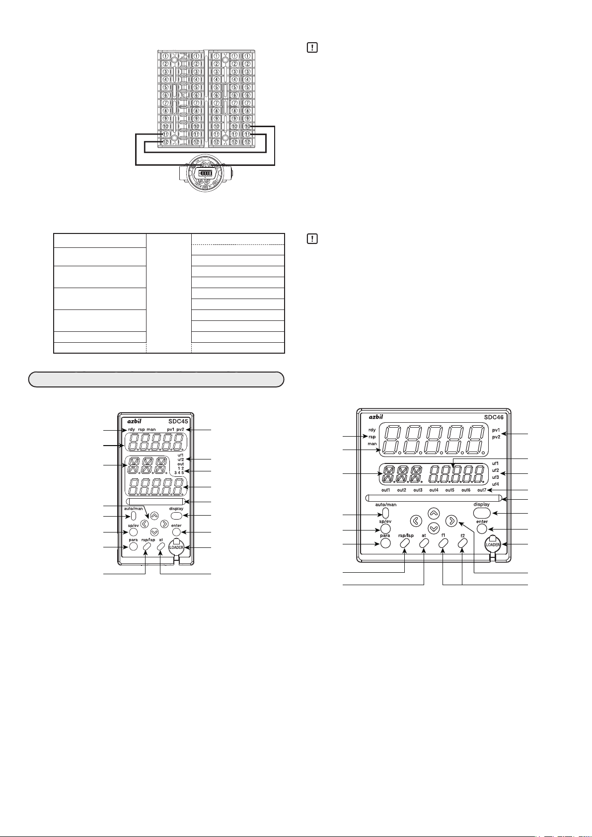
● SDC46背面
出力3(OUT3)
•
(1) モータ駆動
リレー
3
4
出力4(OUT4)
•
(1) モータ駆動
リレー
SDC45/46 詳細編
CP-SP-1218 を
ご覧ください。
(2)
F1
②
F2
③
(2)
⑩
−
⑪
+
⑫
DC24V、30mA
B
C
(2)
1
CT
②
2
CT
③
—
④
(3)
+
⑥
V/mA
−
⑦
mV
+
⑧
⑩
B
⑪
C
⑫
(1)
(3)
T
②
G
③
*
(4)
V
2( P V 2 2 )
−
⑥
⑦
⑧
(3)
V/mA
V/mA
mV
+
1( P V 2 1 )
−
+
−
+
⑥
⑦
⑧
⑩
⑪
⑫
入力定格
(入力端子間)
D EA C F
(2)
COM(−)
①
C1
C2
C3
C4
C5
C6
C7
C8
C1
②
②
C2
③
③
C3
④
④
C4
⑤
⑤
C5
⑥
⑥
C6
⑦
⑦
C7
⑧
⑧
C8
⑨
⑨
⑪DB
SG
その他入力
•
(1)デジタル入力(DI)
(2)カレントトランス
(3)モータフィード
未使用 ④
PV入力2(PV2)
•
( 1 )熱 電 対
(2)測温抵抗体
(3線式)
(3)直流電圧 / 電流
(4)直流電圧 / 電流+
PV入力1(PV1)
•
( 1 )熱 電 対
(2)測温抵抗体
(3線式)
(3)直流電圧 / 電流
⑫
入 力( C T )
バック入力(MFB)
*
直流電圧
•
(DI/DO)
(1) DI
(2) DO
•
(1)
(1)
デジタル
入出力
RS-485
通信
(2)
⑥
B
⑦
C
⑧
B
C
⑩
⑪
⑫
AC
AC
—
D
⑥
B
⑦
C
⑧
(2)
1
2
SG
②
③
(3)
⑦
⑨
V
−
D
B
C
C1
②
C2
③
C3
④
C4
⑤
+
−
+
−
⑪DB
⑫
( 1 )測 温 抵 抗 体
⑥
(2)測温抵抗体
⑦
(3)直流電圧
⑧
⑩
( 1 )測 温 抵 抗 体
⑪
(2)測温抵抗体
⑫
:DC − 100 ~+100mV(PV 入力、直流電圧mVレンジ)
DC−1 ~+ 10V(PV入力、直流電圧Vレンジ)
DC0 ~ 20mA(PV 入力、直流電流)
AC0 ~ 69mA(カレントトランス入力)
AC0 ~ 13.2V(ヒータ電源電圧入力)
ヒータ電源
•
電圧入力
(AC)
未使用
PV入力2
•
(PV2)
(3線式)
(4線式)
PV入力1
•
(PV1)
(3線式)
(4線式)
デジタル
•
入力(DI)
出力6
•
(OUT6)
電流
出力7
•
(OUT7)
電流発信器
用電源
RS-485
•
通信
● 電流入力の場合 ● 電圧入力の場合
発信器
発信器用電源
(DC24V)
PV入力
(4〜20mA)
J3
発信器
250Ω精密抵抗
発信器用電源
(DC24V)
PV入力
(DC1〜5V)
Page 4
● SDC46A1A2C0P0000における出力5 の電源と PV1 の接続例
圧力発信器など
D EA C F
取り扱い上の注意
• DC24V(出力5)
A列⑪:+
A列⑫:−
• PV1(DC4 〜 20mA)
F列⑩:+
F列⑪:−
+
−
● 入出力間アイソレーション
実線で囲まれたものは他の信号と絶縁されています。入出力の有無は形番によります。
電源は、すべての入出力、通信、内部回路と絶縁されています。
PV1
PV2/PV21/PV22
DI-C1 〜 DI-C8 OUT4
DI-D1 〜 DI-D8 OUT6
DI-F1 〜 DI-F2 DO-C1 〜 DO-C8
MFB RS-485通信
CT1/CT2/AC1/AC2 ローダ通信
内部回路
OUT1
OUT2
OUT3
OUT5
OUT7
DO-E1 〜 DO-E8
• 発信器用電源は、本器電源投入と同時に常時電圧を出力します。本
器電源投入前に接続を十分に確認してください。
また、本器電源を入れたまま発信器の接続、取り外しはしないでく
ださい。発信器の故障の原因になります。
• 配線には、シールド付きのものをお使いください。
• 発信器と本器の発信器用電源、PV入力を電流入力として接続した
場合は、必ずPV入力レンジを電流入力(DC4 〜 20mA)にしてから
動作チェックを実施してください。
PV入力レンジが正しく設定されていないとDC24Vが回路に印加
されず、発信器が動作いたしません。
取り扱い上の注意
• ローダジャック部は、内部回路とアイソレートされていません。
ローダを使用しない場合は、必ずキャップをしてください。
• モータ駆動リレーでは、OUT3と OUT4 は絶縁されていません。
各部の名称と機能
● SDC45正面
⑤
①
③
⑨
⑩
⑪
⑬
⑰
① 第 1 表示部 : PV 値(現在の温度など)や設定項目を表示します。
② 第 2 表示部 : SP値(設定温度など)や各設定項目の設定値を表示
します。
③ 補助表示部 : 設定項目の組番号、ループ
を表示します。
* PV 値の入力から PID 演算、制御出力に至るまでの一連の
つながりを総称して、「ループ」と呼びます。
④ MS(マルチステータス)表示灯
: MVや DI/DO 状態を表示します。
⑤ モード表示灯
rdy : READYモードのとき点灯します。
rsp : RSP(リモート設定入力)モードのとき点灯します。
man : MANUAL(手動)モードのとき点灯します。
⑥ 出力表示灯
out1 ~ out7 :
出力ONのとき点灯します。(SDC45はout1 ~ out5)
⑦ ユーザーファンクション表示灯
uf1 ~ uf4 : 設定にて定義した条件で点灯します。
(SDC45はuf1、uf2)
⑧ ループ番号表示灯
pv1、pv2 : 表示しているPV 値のループ番号が点灯します。
⑧
⑦
⑥
②
④
⑫
⑭
⑱
⑯
*
番号、チャンネル番号
● SDC46正面
⑤
①
③
⑩
⑪
⑬
⑰
⑯
⑨ [∧]、[∨]、[<]、[>]キー
: 数値の増減、桁移動や設定項目の移動に使用します。
⑩ [auto/man]キー : AUTO/MANUAL モードを切り替えるときに使用
します。
⑪ [sp/ev]キー : SP/EVバンクを設定するときに使用します。
⑫ [display]キー : 運転表示状態で表示の内容を切り替えるときに使用
します。
⑬ [para]キー : PARA バンクを設定するときに使用します。
⑭ [enter]キー : 設定の変更開始と変更中の数値を確定するときに使
用します。
⑮ [f1]、[f2]キー :
設定で割り付けた機能に使用します。(SDC46だけ)
⑯ [at]キー : オートチューニングの実行/停止を切り替えるとき
に使用します。また、設定にて割り付けた機能にも
使用できます。
⑰ [rsp/lsp]キー : RSP/LSPモードを切り替えるときに使用します。
また、設定で割り付けた機能にも使用できます。
⑱ ローダジャック : ローダケーブルを接続するためのジャックです。
(キャップ付き)
J4
⑧
②
⑦
⑥
④
⑫
⑭
⑱
⑨
⑮
Page 5
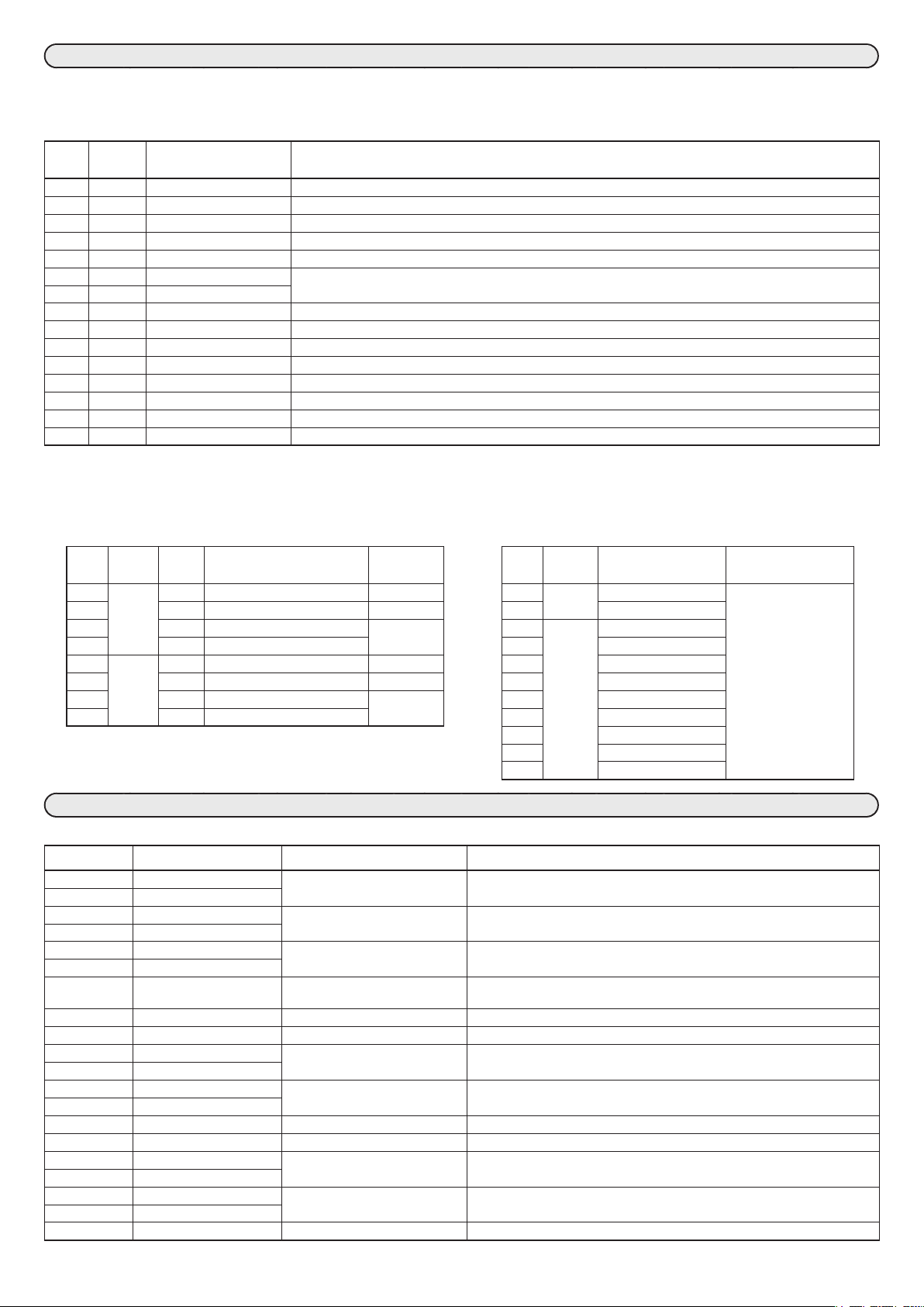
本入力指示精度はセンサタイプにより異なります。
3入力モデルの場合、PV21/22で熱電対は使えません。SDC45R/46Rで熱電対は使えません。
PV-0 1
設定値
センサ
タイプ
1 K −270.0 〜 + 1372.0℃
2 E −270.0 〜 + 1000.0℃
3 J − 200.0 〜 +1200.0℃ −100℃未満:±1.0℃、400℃未満:±0.5℃、400℃以上:±0.1%Reading±1digit
4 T − 270.0 〜 + 400.0℃ −200℃未満:±10.0℃、−100℃未満:±1.0℃、−100℃以上:±0.5℃
5 B 0.0 〜 1800.0℃ 260℃未満:±70℃、800℃未満:±4℃、800℃以上:±2℃
6 R −50.0 〜 + 1768.0℃ 0℃未満:±4.0℃、1000℃未満:±2.0℃、1000℃以上:±0.1%Reading±1digit
7 S −50.0 〜 + 1768.0℃
8
WRe5-26
9
PR40-20
10
Ni-Ni·Mo
11 N − 200.0 〜 +1300.0℃ 0℃未満:±4.0℃、0℃以上:±1.4℃
12 PL II 0.0 〜 1390.0℃ ±1.4℃
13 DIN U − 200.0 〜 + 600.0℃ 0℃未満:±1.0℃、0℃以上:±0.7℃
14 DIN L −200.0 〜 +900.0℃ 0℃未満:±1.5℃、0℃以上:±1.0℃
15
金鉄クロメル
0.0 〜 2300.0℃ 1400℃未満:±1.5℃、1400℃以上:±0.1%Reading±1digit
0.0 〜 1900.0℃ 300℃未満:±40℃、800℃未満:±20℃、800℃以上:±8℃
0.0 〜 1300.0℃ ±1.4℃
−273.0 〜 + 27.0℃ ±1.5℃
レンジ 入力指示精度
PV-01
設定値を表にない値に設定すると入力指示値は0.0固定となります。
−200℃未満:±20.0℃、−100℃未満:±1.0℃、400℃未満:±0.5℃、400℃以上:±0.1%Reading±1digit
−200℃未満:±15.0℃、−100℃未満:±1.0℃、400℃未満:±0.5℃、400℃以上:±0.1%Reading±1digit
3入力モデルの場合、PV21/22で測温抵抗体は使えません。
SDC45R/46Rのリニア入力で測温抵抗体は使えません。
SDC45A/46A/45V/46Vは21、22、31、32が使えます。
SDC45R/46Rは23、24、33、34が使えます。
PV-0 1
センサ
設定値
タイプ
21 Pt100 3 線式 − 200.0 〜 +850.0℃ ± 0.3℃ 41 電 流 4 〜 20mA ± 0.1%FS ± 1digit
22 3線式 −200.00 〜 + 300.00℃ ± 0.15℃ 42 0 〜 20mA
23 3線式 0.00 〜 100.00℃ ±0.050℃ 43 電 圧 0 〜 10mV
24 4線式 0.000 〜 32.000℃ 44 − 10 〜 + 10mV
31 JPt100 3線式 −200.0 〜 +640.0℃ ± 0.3℃ 45 0 〜 100mV
32 3線式 −200.00 〜 + 300.00℃ ± 0.15℃ 46 − 100 〜 + 100mV
33 3線式 0.00 〜 100.00℃ ±0.050℃ 47 0 〜 1V
34 4線式 0.000 〜 32.000℃ 48 − 1 〜 + 1V
結線
方法
レンジ 入力指示
精度
3入力モデルのPV21は41、42、49、50、51が使えます。
3入力モデルのPV22は49、50、51が使えます。
SDC45R/46Rのリニア入力は47、49、50が使えます。
SDC45R/46Rの測温抵抗体入力で直流電圧・直流電流は使えません。
PV-0 1
設定値
センサ
タイプ
49 1 〜 5V
50 0 〜 5V
51 0 〜 10V
レンジ 入力指示精度
本器異常時のアラーム表示と対策を示します。
アラ ームコード 異常名称 原 因 処 置
AL0 1
AL02
AL03
AL04
AL05
AL06
AL 17
AL2 1
AL22
AL25
AL26
AL7 1
AL72
AL8 1
AL82
AL83
AL96
AL97
AL98
AL99
*SDC45V/46Vだけ
PV1入力上限異常 センサ断線、誤配線、
PV1入力下限異常
PV2/PV21入力上限異常 センサ断線、誤配線、
PV2/PV21入力下限異常
PV22入力上限異常 センサ断線、誤配線、
PV22入力下限異常
制御用レンジ異常 制御用レンジ誤設定 制御用レンジ上下限の再設定
MFB入力異常 断線、誤配線 配線の確認
モータ調整異常 断線、誤配線、モータ電源断 配線の確認、モータ電源の確認、再調整
CT1入力異常 CT入力オーバーレンジ、
CT2入力異常
PV1冷接点補償異常 端子温度異常(熱電対) 周囲温度の確認
PV2冷接点補償異常
バッテリ電圧低下
内蔵時計異常
ボード構成異常 ハードウェア故障 本体交換
メインボード異常
パラメータ異常 データ確定中に電源断、
調整データ異常
ROM異常 ROM(メモリ)故障 電源再投入、本体交換
*
*
PV1レンジ種類誤設定
PV2/PV21レンジ種類誤設定
PV22レンジ種類誤設定
CT入力誤設定
バッテリ消耗 バッテリ交換
バッテリ消耗、ハードウェア故障 バッテリ交換後に時計を再設定、本体交換
ノイズなどでデータ破壊
配線の確認、PV1レンジ種類の再設定(
PV1レンジ上下限の再設定(
配線の確認、PV2/PV21レンジ種類の再設定(
PV2/PV21レンジ上下限の再設定(
配線の確認、PV22レンジ種類の再設定(
PV22レンジ上下限の再設定(
(
CT入力の確認、CT入力設定の再設定
電源再投入、データの再設定(
交換
:制御用レンジ下限、
Cnt.05
PV-04
PV-04
Cnt.06
AL97
:レンジ下限、
PV-04
:レンジ下限、
:設定データ、
)、
PV-0 1
:レンジ下限、
PV-0 1
:制御用レンジ上限)
PV-05
PV-0 1
)、
PV-05
AL98
:レンジ上限)
)、
:レンジ上限)
PV-05
:レンジ上限)
:調整データ)、本体
Page 6
形番構成
■ SDC45A/45V(形番が14 桁の場合)
基本
形番
モデル
出 力
電
源
1 、2 3 、4 5 6 、7 1 2
C45A
C45V
1
2
3 3入力(フルマルチ1点、リニア2点)
A
D
1
2
C0
D0
V0
RR
CC
VV
CV
SS モータ駆動トライアック+MFB入力 1点
0
R
C
D
P
0
*
1 SDC45Vでは選択できません
*
2 SDC45Vだけで選択できます
*
3 出力3、4に「SS」を選択した場合は
DI はありません
*
4 出力3、4に「SS」を選択した場合は
DI8 点です
*
5 出力3、4に「SS」を選択した場合は
選択できません
*
6 AC電源モデルだけで選択できます
■ SDC45R
基本
モデル
形番
C45R 高精度モデル(□ 48× 96)
1 2入力(測温抵抗体1点+リニア1点)
2 2入力(測温抵抗体2点)
出 力
電
源
1 、2 3 、4 5 6 、7 1 2
A AC100 〜 240V電源
D DC24V電源
1 リレー 1a1b:1点
2 リレー 1a:2点
CC 電流+電流
VV 電圧パルス+電圧パルス
R リレー 1a
0 なし
追加処理
オプ
ション
標準モデル
演算機能モデル
1入力(フルマルチ1 点)
2入力(フルマルチ2点)
AC100 〜 240V電源
DC24V 電源
リレー 1a1b:1点
リレー 1a:2点
電流(OUT3)
連続電圧(OUT3)
電圧パルス(OUT3)
リレー 1a+リレー 1a
電流+電流
電圧パルス+電圧パルス
電流(OUT3)+電圧パルス(OUT4)
なし
リレー 1a
電流
連続電圧
発信器用電源
なし
0
1
2
3
4
5
6
7
オプ
ション
DI2 点(DI-F1/2)
DI10 点
DI2点+DO8点
DI2点+DO8 点+RS-485
CT 入力2 点
CT入力2 点+DI8点
CT入力2点+DO8点
CT入力2 点+DO8点+ RS-485
0
なし
D
検査成績書付き
Y
トレーサビリティ証明対応
0
なし
1
すべて橙色表示
A
UL対応品
B
UL対応品、すべて橙色表示
追加処理
*4
*5
0 AC入力2点
1 AC入力 2 点+DI8 点
8 AC入力 2 点+RS-485
D 検査成績書付き
Y トレーサビリティ証明対応
0 なし
A UL 対応品
仕 様
*3
*3
*5
仕 様
■ SDC46A/46V(形番が14 桁の場合)
基本 形番モデル
C46A 標準モデル
C46V 演算機能モデル
*1
*2
*6
*3
*
1 SDC46Vでは選択できません
*
*5
*5
2 SDC46Vだけで選択できます
*
3 出力 3、4 に「CC」かつ出力 5 に「C」
を選択した場合は選択できません
*
4 出力 3、4に「R1」を選択した場合
は「0」だけ選択できます
*
5 出力 3、4に「SS」または「R1」を選
択した場合はDIはありません
*
6 出力 3、4に「SS」または「R1」を選
択した場合はDI12点となります
*
7 出力 3、4に「SS」または「R1」を選
択した場合は選択できません
*
8 AC 電源モデルだけで選択できま
す
電
出 力 オプ
源
1 、2 3 、4 5 6 、7 1 2
1 1入力(フルマルチ1点)
追加処理 仕 様
ション
*1
2 2入力(フルマルチ2点)
3 3 入力(フルマルチ1 点、リニア2点)
A AC100 〜 240V電源
D DC24V電源
1 リレー 1a1b:1点
2 リレー 1a:2点
C0 電流(OUT3)
D0 連続電圧(OUT3)
V0 電圧パルス(OUT3)
RR リレー 1a+リレー 1a
CC 電流+電流
VV 電圧パルス+電圧パルス
CV 電流(OUT3)+電圧パルス(OUT4)
SS モータ駆動トライアック+MFB入力1点
R1 モータ駆動リレー+ MFB入力1 点
0 なし
R リレー 1a
C 電流
D 連続電圧
P 発信器用電源
*4
*4
*4
*4
*4
0 なし
1 電流(OUT6)
2 発信器用電源(OUT7)
3 電流+電流
4 電流(OUT6)+発信器用電源(OUT7)
0 DI2点(DI-F1/2)
1 DI14点
2 DI14点+ DO8 点
3 DI14点+ DO8 点+RS-485
4 CT入力2点
5 CT入力 2 点+DI12 点
*3
*5
*6
*6
*6
*7
*7
6 CT入力 2 点+DI12 点+ DO8点
7
CT入力2点+DI12点+DO8点+RS-485
0 なし
D 検査成績書付き
Y トレーサビリティ証明対応
0 なし
1 すべて橙色表示
A UL 対応品
B UL 対応品、すべて橙色表示
*2
*8
*8
*7
*7
■ SDC46R
基本 形番モデル
C46R 高精度モデル(□ 96× 96)
電
出 力 オプ
源
1 、2 3 、4 5 6 、7 1 2
追加処理 仕 様
ション
1 2入力(測温抵抗体1点+リニア 1 点)
2 2入力(測温抵抗体2点)
A AC100 〜 240V電源
D DC24V電源
1 リレー 1a1b:1点
2 リレー 1a:2点
CC 電流+電流
VV 電圧パルス+電圧パルス
R リレー 1a
0 なし
3 電流+電流
0 AC入力2点
1 AC入力 2 点+DI12 点
8 AC入力 2 点+RS-485
D 検査成績書付き
Y トレーサビリティ証明対応
0 なし
A UL 対応品
■ SDC45A(形番が7桁の場合)
形番
オプ ション
1 2
基本 形番短縮
LED表示はすべて橙色です。
仕 様
C45A 標準モデル :警報出力2 点(OUT1/2)標準装備
0 —
0 一般形1 :リレー出力2 点(OUT3/4)+電流出力(OUT5)+DI2点
1 一般形2 :電流(OUT3)+電圧パルス(OUT4)+リレー出力(OUT5)
(DI-F1/2)
+DI2点(DI-F1/2)
2 位置比例形1:トライアック出力 2点(OUT3/4)+リレー出力(OUT5)
3 一般形3 :電流出力2 点(OUT3/4)+発信器用電源 DC24V(OUT5)
4 位置比例形2:トライアック出力 2点(OUT3/4)+発信器用電源 DC24V
+DI2点(DI-F1/2)
(OUT5)
0 なし
1 通信(RS-485)+ PV入力 2+ DO8 点
2 PV入力2 + DO8点
3 DO8点
4 PV入力2
■ SDC46A(形番が7桁の場合)
基本 形番短縮形番オプ ション 仕 様
C46A 標準モデル :
J6
1 2
警報出力2点(OUT1/2)+電流出力1点(OUT6)標準装備
0 —
0 一般形1 :リレー出力2点(OUT3/4)+電流出力(OUT5)+DI2点
1 一般形2 :電流(OUT3)+電圧パルス(OUT4)+リレー出力(OUT5)
(DI-F1/2)
+DI2点(DI-F1/2)
2 位置比例形1:トライアック出力 2点(OUT3/4)+リレー出力(OUT5)
3 一般形3 :リレー出力2 点(OUT3/4)+電流出力(OUT5)+発信器用
4 位置比例形2:トライアック出力 2点(OUT3/4)+リレー出力(OUT5)+
電源DC24V(OUT7)+ DI2点(DI-F1/2)
発信器用電源DC24V(OUT7)
0 なし
1 通信(RS-485)+ PV入力 2+ DI12 点+DO8 点
2 PV入力2 + DI12点+ DO8 点
3 DI12点+DO8 点
4 PV入力2
LED表示はすべて橙色です。
Page 7

保 守
清 掃 :計器の汚れを取る場合は、柔らかい布での乾拭きを行っ
部品交換 :部品交換は、おやめください。
ヒューズ交換:AC 電源モデルで電源配線に設けたヒューズを交換する
注:UL規格対応のためには、下記ヒューズをご使用ください。
メーカー :LITTELFUSE INC.
形 番 :Type 215001 または Type 477001
定 格 :AC250V、1A
てください。シンナー、ベンゼンなどの有機溶剤や洗剤
は使用しないでください。
ときは、必ず指定の規格品を使用してください。
規格 IEC127、遮断速度 遅動タイプ(T)、
定格電圧 250V、定格電流 1.0A
EU
入力インピーダンス :電流入力で 110 Ω以下
冷接点補償精度 :±0.5℃(基準条件)
冷接点補償方法 :計器内にて補償、および計器外での補償
許容入力電圧 :DC − 1.0 ~+3.5V(熱電対レンジ)
±1.0℃(周囲温度 0 ~ 50℃にて)
(0℃だけ)選択可能
DC−1.0 ~+2.5V(直流電圧、mV レンジ)
DC−10 ~+25V(直流電圧、V レンジ)
DC−1 ~+4V(直流電流レンジ)
■ モータフィードバック入力(MFB)
許容ポテンショメ−タ値
指示精度 :±0.2%FS(基準条件にて)
サンプリング周期 :100ms
:100 ~ 2,500Ω
廃棄について(SDC45V/46Vだけ)
注意
作業は、電源を切った状態で10分以上放置後に、電池を取り外
してください。感電、火傷のおそれがあります。
バッテリを取り外すと、一部の設定値や内部動作状態データが
消滅します。
取り外したバッテリは、各自治体の条例、または規則に従って
適切に処理してください。
本器を廃棄する場合は、下記に従ってバッテリを取り外し、各自治体の
条例、または規則に従って適切に処理してください。
■ バッテリの取り外し手順
① コンソール部を本体ケースより引き出します。
コンソール部とケース間の溝(上下左右にあります)にマイナスド
ライバを差し込み、ドライバをこじるようにして徐々に引き抜い
てください。
② バッテリを、バッテリホルダから取り外します。
バッテリを、持ち上げながら引いてください。
バッテリ
溝
取り扱い上の注意
• SDC45/46Vは、メモリバックアップ用としてバッテリを内蔵して
います。交換用バッテリは下記を使用してください。
当社形番:81446345-001
■ カレントトランス入力
使用カレントトランス :QN212A*(φ12、800ターン)
QN206A
*UL認定品ではありません。
入力レンジ :AC0 ~ 50A
測定電流範囲 :AC0.0 ~ 55.0A(AC0.4A 未満は精度規定外)
指示精度 :±3%FS±1digit
指示分解能 :AC0.1A
入力インピ−ダンス :10 Ω(typ)
*
(φ6、800ターン)
■ ヒータ電源電圧入力
入力周波数 :50Hz/60Hz
入力レンジ :AC0 ~ 12V
測定電圧範囲 :AC0 ~ 13.2V(AC0.5V 未満は精度規定外)
指示精度 : ± 0.5%FS ± 1digit
指示分解能 :AC0.01V
入力インピーダンス :126k Ω(typ)
推奨電源電圧検出用
トランス :81406725-003
*UL認定品ではありません。
*
■ 外部スイッチ入力
● デジタル入力(DI)
接続可能出力 :無電圧接点またはトランジスタ(シンク型)
開放時端子電圧 :DC7V± 15%(基準条件にて)
短絡時端子電流 :3 ~ 7mA(基準条件にて)
ON接点抵抗 :500Ω以下(基準条件にて)
OFF接点抵抗 :100kΩ以上(基準条件にて)
許容ON残留電圧 :1.5V以下(基準条件にて)
許容OFF漏れ電流 :0.1mA以下(基準条件にて)
仕 様
■ PV入力
熱電対 :K、E、J、T、B、R、S、N(JISC1602-1995)
WRe5-26(ASTME988-96(Reapproved2002))、
PR40-20(ASTME1751-00)、
Ni-Ni·Mo(ASTME1751-00)、
PLII(ASTME1751-00)、
DINU、DINL(DIN43710-1985)
金鉄クロメル(ASTME1751-00)
測温抵抗体 :Pt100(JIS C 1604-1997)
JPt100(JIS C 1604-1989)
直流電圧(mV レンジ):0 ~ 10mV、−10 ~+10mV、0 ~ 100mV、
−100 ~+100mV
直流電圧(V レンジ) :0 ~ 1V、−1 ~+1V、1 ~ 5V、0 ~ 5V、
0 ~ 10V
直流電流 :4 ~ 20mA、0 ~ 20mA
サンプリング周期 :25、50、100、300ms(設定による)
(SDC45A/46Aの場合)
100ms(SDC45V/46V/45R/46R の場合)
指示精度(基準条件にて)
熱電対 :±0.1%Reading±1digit(レンジ、計測温度に
よる)
測温抵抗体 :±0.05 ~ 0.3℃(レンジによる)
直流電圧・直流電流:±0.1%FS ± 1digit
■ 制御出力
(制御出力(OUT)・補助出力(AUX)・イベント出力(EV))
● リレー出力(出力 1、2)
接点構成 :1a1bまたは1a(形番により選択)
接点定格 : 3A AC250V/DC30V 1a1b、抵抗負荷
接点電圧 :AC250V以下/DC30V以下
電気的寿命 :10 万回以上(定格負荷)
最小開閉仕様 : 100mA/DC5V 1a1b、10mA/DC5V 1a
1A AC250V/DC30V 1a、抵抗負荷
● リレー出力(出力 3、4、5)
接点構成 :1a
接点定格 :3A AC250V/DC30V(抵抗負荷)
接点電圧 :AC250V以下/DC125V以下
電気的寿命 :10 万回以上(定格負荷)
最小開閉仕様 :100mA/DC5V
● 電流出力
出力電流 : DC4 ~ 20mA(DC2.4 ~ 21.6mA)
負荷抵抗 :600Ω以下
出力精度 :±0.1%FS以下(基準条件にて)
出力分解能 :1/15,000
開放時電圧 :DC23V 以下
J7
DC0 ~ 20mA(DC0.0 ~ 22.0mA)
Page 8

● 連続電圧出力
出力電圧 : DC0 ~ 5V(DC0.0 ~ 5.5V)
DC1 ~ 5V(DC0.6 ~ 5.4V)
DC0 ~ 10V(DC0.0 ~ 11.0V)
負荷抵抗 :1kΩ以上
負荷制限電流 :21mA 以下(基準条件における標準値)
出力精度 :±0.1%FS以下(基準条件にて)
出力分解能 :1/20,000(0 ~ 10Vレンジ)
● 電圧パルス出力
出力電圧 :DC12V+15%/−10%
負荷電流 :30mA以下
負荷制限電流 :52mA(基準条件における標準値)
OFF漏れ電流 :0.1mA以下
● モータ駆動トライアック出力(出力 3、4)
出力構成 :1a(出力3)+ 1a(出力 4)
適合モータ : ECM3000F1□□□
(AC100V リレー接点入力)
● モータ駆動リレー出力(出力 3、4)
接点構成 : 出力 3 と出力 4 の相互切替
(出力3と出力4の同時出力OFF機能あり)
接点定格 : 2A AC250V 以下 /(cos φ= 0.4)
2.5A DC24V(L/R = 0.7ms)
接点電圧 :AC250V以下/DC125V以下
電気的寿命 :10 万回以上(定格負荷)
最小開閉仕様 :40mA/DC24V
● 発信器用電源
出力電圧 :DC24V±10%
負荷電流 :30mA以下
負荷制限電流 :45mA(基準条件における標準値)
リップル電圧 :100mV 以下(基準条件にて)
● デジタル出力(DO)
出力形式 : トランジスタ(シンク型)
負荷電圧 :DC4.5 ~ 28V
負荷電流 :最大70mA/1点、最大500mA/1台
ON残留電圧 :0.5V以下
OFF漏れ電流 :0.1mA以下
■ RS-485通信
伝送路 :RS-485、3 線式マルチドロップ
伝送速度 :4800、9600、19200、38400bps
伝送距離 :500m 以下
接続台数 :最大 32 台(親局 1 台含む)
通信方式 :半 2 重、調歩同期式
終端抵抗 :150 Ω、1/2W を線路両端に接続
ビット長 :8 ビットまたは 7 ビット
ストップビット :1 ビットまたは 2 ビット
パリティビット : 偶数パリティ、奇数パリティ、またはパリティ
なし
通信プロトコル :CPL、Modbus 準拠
■ 環境条件
● 基準条件
周囲温度 :23±2℃(SDC45A/46A/45V/46V の場合)
周囲湿度 :60±5%RH
電源電圧 :AC105V±1%(AC100 ~ 240V電源モデル)
電源周波数 : 50±1Hzまたは60±1Hz
振 動 :0m/s
衝 撃 :0m/s
取付角度 :基準面±3°
23±0.1℃(SDC45R/46R の場合)
DC24V±5%(DC24V 電源モデル、
SDC45A/46A/45V/46Vの場合)
DC24V±2%(DC24V 電源モデル、
SDC45R/46Rの場合)
(AC100 ~ 240V 電源モデル)
2
2
● 動作条件
周囲温度 : 0 ~ 50℃(SDC45A/46A/45V/46Vの場合)
20 ~ 25℃(SDC45R/46R の場合)
周囲湿度 :10 ~ 90%RH(結露なきこと)
電源電圧 : AC85 ~ 264V(AC100 ~ 240V電源モデル)
DC21.6 ~ 26.4V(DC24V 電源モデル)
電源周波数 : 50±2Hzまたは60±2Hz
(AC100 ~ 240V 電源モデル)
振 動 :0 ~ 2m/s
衝 撃 :0 ~ 10m/s
2
(10 ~ 60Hz X、Y、Z 各方向 2h)
2
取付角度 :基準面±10°
高 度 :2000m以下
● 輸送保管条件
周囲温度 : − 20 ~+70℃
周囲湿度 :10 ~ 95%RH(結露なきこと)
2
振 動 :0 ~ 5m/s
衝 撃 :0 ~ 500m/s
(10 ~ 60Hz X、Y、Z 各方向 2h)
2
■ メモリバックアップ
バックアップ方式 : シリアルEEPROM
書替回数 : EEPROM 100 万回以下
バックアップ時間 : EEPROM 10年
SRAMのバッテリ+電気二重層コンデンサ
バックアップ(SDC45V/SDC46V)
SRAM 制限なし
SRAM 30min
(電気二重層コンデンサ、1時間以上充電後周
囲温度35℃以下無通電放置)
3年(バッテリ、周囲温度 10 ~ 35℃無通電放
置)
■ その他仕様
消費電力 : 30VA 以下(SDC45 AC100 ~ 240V電源モ
電源投入時突入電流 : 35A以下/10ms以下(AC100 ~ 240V電源モ
停電不感帯時間 : 20ms 以上
質 量 : 400g 以下(SDC45、専用取付部品を含む)
端子ねじ締付トルク :0.4 ~ 0.6N・m
保護構造 :IP65(動作条件にて)
適合規格 : EN61010-1、
過電圧カテゴリ : Category II(IEC60364-4-443、IEC60664-1)
許容汚染度 :Pollution degree 2
Modbus™ is a trademark and the property of Schneider Electric SE, its
subsidiaries and affiliated companies.
〔ご注意〕 この資料の記載内容は、お断りなく変更する場合もありますので
ご了承ください。
本 社 〒100-6419東京都千代田区丸の内 2-7-3 東京ビル
北海道支店
東北支店
北関東支店
東京支社
☎(011)211ー1136
☎(022)290ー1400
☎(048)621ー5070
☎(03)6432ー5142
製品のお問い合わせは…
コールセンター: 0466-20-2143
〈アズビル株式会社〉 http://www.azbil.com/jp/
〈COMPOCLUB〉 http://www.compoclub.com
J8
デル)
40VA以下(SDC46 AC100 ~ 240V 電源モ
デル)
12W以下(SDC45 DC24V 電源モデル)
15W以下(SDC46 DC24V 電源モデル)
デル)
20A以下/10ms以下(DC24V電源モデル)
700g以下(SDC46、専用取付部品を含む)
EN61326-1(For use in industrial locations)
EMC試験中、±10%FSに相当する指示値や
出力値の変動が生じる場合があります。
中部支社
関西支社
中国支店
九州支社
☎(052)324ー9773
☎(06)6881ー3383 4
☎(082)554ー0750
☎(093)285ー3530
2007年 4月 初版発行(W)
2018年 5月 改訂20 版(M)
(27)
Page 9

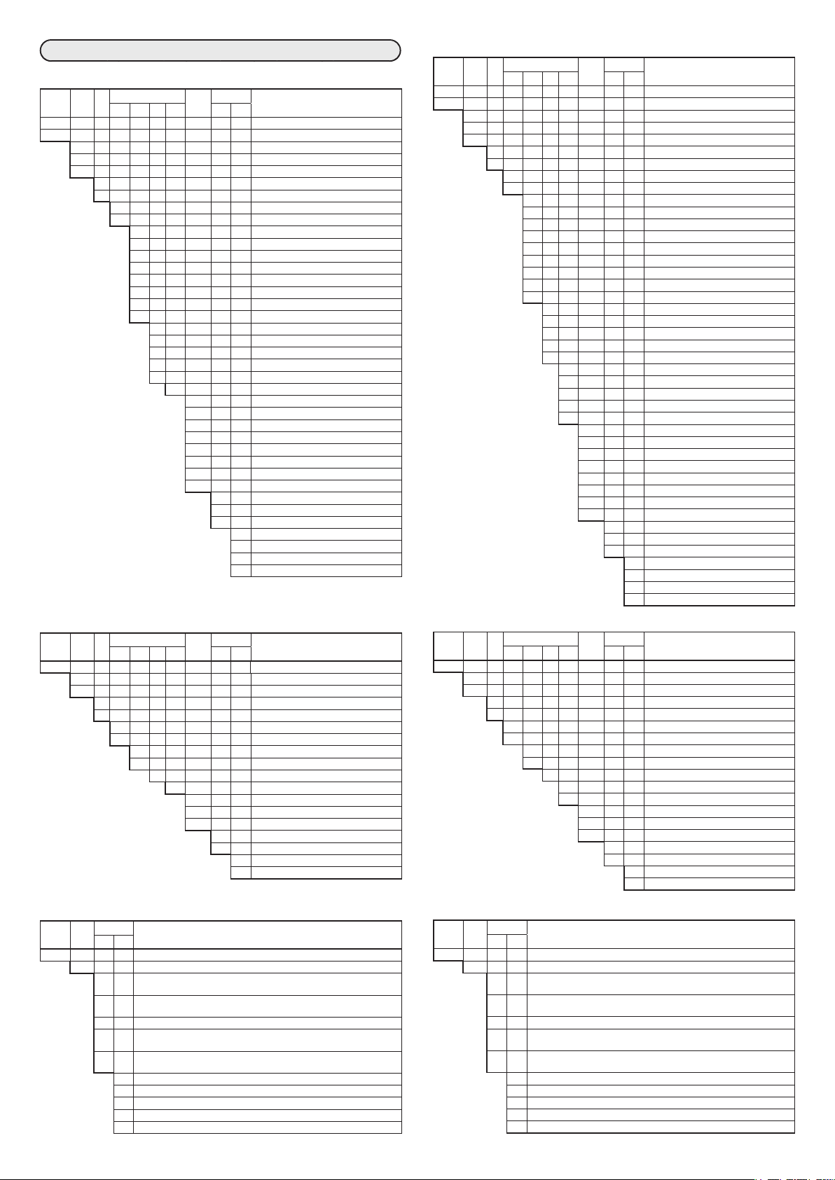
キー操作と表示の遷移
注:【 】はバンク名を表しています
運転表示
電源ON
設定表示
SP/EVバンク
【SP組選択】
(点滅)
[enter]キー
[
[sp/ev]キー
]キ ー
<
または
(点灯)
SPNO
L. 1.
SPNO
L.2.
1ループの場合
2 ループの場 合
【ループ1マルチSP】
[<]キ ー ま た は
[sp/ev]キー
[sp/ev]キー
2秒押し
AUTOモードのとき
MANUALモードのとき
2ループともAUTOモードのとき
MANUALモードのとき
[sp/ev]キー2秒押し
【ループ2マルチSP】
(点滅)
(点灯)
LSP.0 1
L. 1.
PI D.0 1
PI D.0 1
L. 1.
L. 1.
LSP.02
L. 1.
PI D.02
L. 1.
LSP.03
L. 1.
PI D.03
L. 1.
LSP.04
L. 1.
PI D.04
L. 1.
LSP.05
L. 1.
PI D.05
L. 1.
LSP.06
L. 1.
PI D.06
L. 1.
LSP.07
L. 1.
PI D.07
L. 1.
LSP.08
L. 1.
PI D.08
L. 1.
LSP.09
L. 1.
PI D.09
L. 1.
LSP. 10
L. 1.
PI D. 10
L. 1.
LSP. 1 1
L. 1.
PI D. 1 1
L. 1.
LSP. 12
L. 1.
PI D. 12
L. 1.
LSP. 13
L. 1.
PI D. 13
L. 1.
LSP. 14
L. 1.
PI D. 14
L. 1.
LSP. 15
L. 1.
PI D. 15
L. 1.
LSP. 16
L. 1.
PI D. 16
L. 1.
マルチSP使用時
C-010
(
(点滅)
(点灯)
LSP.0 1
L.2.
PI D.0 1
L.2.
LSP.02
L.2.
PI D.02
L.2.
LSP.03
L.2.
PI D.03
L.2.
LSP.04
L.2.
PI D.04
L.2.
LSP.05
L.2.
PI D.05
L.2.
LSP.06
L.2.
PI D.06
L.2.
LSP.07
L.2.
PI D.07
L.2.
LSP.08
L.2.
PI D.08
L.2.
LSP.09
L.2.
PI D.09
L.2.
LSP. 10
L.2.
PI D. 10
L.2.
LSP. 1 1
L.2.
PI D. 1 1
L.2.
LSP. 12
L.2.
PI D. 12
L.2.
LSP. 13
L.2.
PI D. 13
L.2.
LSP. 14
L.2.
PI D. 14
L.2.
LSP. 15
L.2.
PI D. 15
L.2.
LSP. 16
L.2.
PI D. 16
L.2.
=0)
ループ1PV値
[display]キー
ループ1PV値
ループ1SP値
ループ1PV値
[display]キー
ループ2PV値
SP/EVバンク表示させた直前の運転表示に戻る
【 ル ープ1レシピ 】 【ループ 2レシピ】
(点滅)
(点灯)
SP
1.0 1.
E0 1
E0 1
1.0 1.
1.
E0 1.SB
E0 1.SB
1.0 1.
1.
E02
E02
1.0 1.
1.
E02.SB
E02.SB
1.0 1.
1.
E03
E03
1.0 1.
1.
E03.SB
E03.SB
1.0 1.
1.
E04
E04
1.0 1.
1.
E04.SB
E04.SB
1.0 1.
1.
E05
E05
1.0 1.
1.
E05.SB
E05.SB
1.0 1.
1.
E06
E06
1.0 1.
1.
E06.SB
E06.SB
1.0 1.
1.
E07
E07
1.0 1.
1.
E07.SB
E07.SB
1.0 1.
1.
E08
E08
1.0 1.
1.
E08.SB
E08.SB
1.0 1.
1.
P
P
1.0 1.
1.
I
I
1.0 1.
1.
D
D
1.0 1.
1.
OL
OL
1.0 1.
1.
OH
OH
1.0 1.
1.
RE
RE
1.0 1.
1.
P-C
P-C
1.0 1.
1.
I -C
I -C
1.0 1.
1.
D-C
D-C
1.0 1.
1.
OL.C
OL.C
1.0 1.
1.
OH.C
OH.C
1.0 1.
1.
OI
OI
1.0 1.
1.
レシピ使用時(
16.
16.
16.
16.
16.
16.
16.
16.
16.
16.
16.
16.
16.
16.
16.
16.
16.
16.
16.
16.
16.
16.
16.
16.
16.
16.
16.
16.
(点滅)
(点灯)
SP
2.0 1.
E09
E09
2.0 1.
2. 16.
E09.SB
E09.SB
2.0 1.
2. 16.
E 10
E 10
2.0 1.
2. 16.
E 10.SB
E 10.SB
2.0 1.
2. 16.
E 1 1
E 1 1
2.0 1.
2. 16.
E 1 1.SB
E 1 1.SB
2.0 1.
2. 16.
E 12
E 12
2.0 1.
2. 16.
E 12.SB
E 12.SB
2.0 1.
2. 16.
E 13
E 13
2.0 1.
2. 16.
E 13.SB
E 13.SB
2.0 1.
2. 16.
E 14
E 14
2.0 1.
2. 16.
E 14.SB
E 14.SB
2.0 1.
2. 16.
E 15
E 15
2.0 1.
2. 16.
E 15.SB
E 15.SB
2.0 1.
2. 16.
E 16
E 16
2.0 1.
2. 16.
E 16.SB
E 16.SB
2.0 1.
2. 16.
P
P
2.0 1.
2. 16.
I
I
2.0 1.
2. 16.
D
D
2.0 1.
2. 16.
OL
OL
2.0 1.
2. 16.
OH
OH
2.0 1.
2. 16.
RE
RE
2.0 1.
2. 16.
P-C
2.0 1.
I -C
2.0 1.
D-C
2.0 1.
OL.C
2.0 1.
OH.C
2.0 1.
OI
2.0 1.
C-010
P-C
2. 16.
I -C
2. 16.
D-C
2. 16.
OL.C
2. 16.
OH.C
2. 16.
OI
2. 16.
=1)
[display]キー
ループ1MV値
ループ1PV値
ループ1SP値
【RSP】 【イ ベ ント 設 定 】
(点滅)
(点灯)
RSP
L. 1.
PI D
L. 1.
RSP使用時
加熱冷却制御時
ループ1PV値
ループ1加熱 側MV値
[display]キー
[display]キー
ループ1PV値
ループ1MV値
加熱冷却制御時
ループ1PV値
ループ1冷却側MV値
[display]キー
[display]キー
加熱冷却制御時
ループ1PV値
ループ1加熱 側MV値
[display]キー
加熱冷却制御時
ループ1PV値
ループ1冷却側MV値
[display]キー
ループ2PV値
ループ2SP値
[display]キー
(ループ1のとき) (ループ2のとき)
[display]キー
(点滅)
(点灯)
E0 1
E0 1.SB
E02
E02.SB
E03
E03.SB
E04
E04.SB
E05
E05.SB
E06
E06.SB
E07
E07.SB
E08
E08.SB
[<]キ ー
[sp/ev]キー
E09
E09.SB
E 10
E 10.SB
E 1 1
E 1 1.SB
E 12
E 12.SB
E 13
E 13.SB
E 14
E 14.SB
E 15
E 15.SB
E 16
E 16.SB
マルチSP使用時
C-010
(
=0)
または
PARAバンク
【モ ード】
(点滅)
[enter]キー
[<]キ ー
[para]キー
または
(点灯)
R---R
L. 1.
A---M
L. 1.
AT
L. 1.
L---R
L. 1.
CB
L. 1.
R---R
L.2.
A---M
L.2.
AT
L.2.
L---R
L.2.
CB
L.2.
[<]キ ー
または
[ p a r a ]キ ー
[para]キー
2秒押し
[para]キー 2 秒押し
【ループ1PID】
(点滅)
(点灯)
p-0 1
L. 1.
I -0 1
L. 1.
d-0 1
L. 1.
OL-0 1
L. 1.
OH-0 1
L. 1.
RE-0 1
L. 1.
p-0 1C
L. 1.
I -0 1C
L. 1.
d-0 1C
L. 1.
OL.0 1C
L. 1.
OH.0 1C
L. 1.
p- 16
L. 1.
I - 16
L. 1.
d- 16
L. 1.
OL- 16
L. 1.
OH- 16
L. 1.
RE- 16
L. 1.
p- 16C
L. 1.
I - 16C
L. 1.
d- 16C
L. 1.
OL. 16C
L. 1.
OH. 16C
L. 1.
【ループ2PID】
(点滅)
(点灯)
p-0 1
L.2.
I -0 1
L.2.
d-0 1
L.2.
OL-0 1
L.2.
OH-0 1
L.2.
RE-0 1
L.2.
p-0 1C
L.2.
I -0 1C
L.2.
d-0 1C
L.2.
OL.0 1C
L.2.
OH.0 1C
L.2.
p- 16
L.2.
I - 16
L.2.
d- 16
L.2.
OL- 16
L.2.
OH- 16
L.2.
RE- 16
L.2.
p- 16C
L.2.
I - 16C
L.2.
d- 16C
L.2.
OL. 16C
L.2.
OH. 16C
L.2.
【SPコンフ】
(点滅)
(点灯)
LMT.0 1
L. 1.
LMT.02
L. 1.
CSP.0 1
L. 1.
CSP.02
L. 1.
CSP.03
L. 1.
CSP.04
L. 1.
CSP.05
L. 1.
CSP.06
L. 1.
CSP.07
L. 1.
CSP.08
L. 1.
CSP.09
L. 1.
CSP. 10
L. 1.
CSP. 1 1
L. 1.
CSP. 12
L. 1.
RRA.0 1
L. 1.
RRA.02
L. 1.
RRA.03
L. 1.
RRA.04
L. 1.
RRA.05
L. 1.
RRA.06
L. 1.
RRA.07
L. 1.
RRA.08
L. 1.
LMT.0 1
L.2.
LMT.02
L.2.
CSP.0 1
L.2.
CSP.02
L.2.
CSP.03
L.2.
CSP.04
L.2.
CSP.05
L.2.
CSP.06
L.2.
CSP.07
L.2.
CSP.08
L.2.
PARAバンク表示させた直前の運転表示に戻る
【イベ ントコン フ】
CSP.09
L.2.
CSP. 10
L.2.
CSP. 1 1
L.2.
CSP. 12
L.2.
RRA.0 1
L.2.
RRA.02
L.2.
RRA.03
L.2.
RRA.04
L.2.
RRA.05
L.2.
RRA.06
L.2.
RRA.07
L.2.
RRA.08
L.2.
(点滅)
(点灯)
EP-0 1
0 1.
EP-02
0 1.
EP-03
0 1.
EP-04
0 1.
EP-05
0 1.
EP-06
0 1.
EP-07
0 1.
EP-08
0 1.
EP-09
0 1.
EP-0 1
16.
EP-02
16.
EP-03
16.
EP-04
16.
EP-05
16.
EP-06
16.
EP-07
16.
EP-08
16.
EP-09
16.
【制御】
I NP.0 1
L. 1.
I NP.02
L. 1.
I NP.03
L. 1.
CNT.0 1
L. 1.
CNT.03
L. 1.
CNT.04
L. 1.
CNT.05
L. 1.
CNT.06
L. 1.
CNT.07
L. 1.
CNT.08
L. 1.
CNT.09
L. 1.
CNT. 10
L. 1.
ETD.0 1
L. 1.
ETD.02
L. 1.
ETD.03
L. 1.
ETD.04
L. 1.
ETD.05
L. 1.
ETD.06
L. 1.
ETD.07
L. 1.
ETD.08
L. 1.
ETD.09
L. 1.
ETD. 12
L. 1.
ETD. 13
L. 1.
ETD. 14
L. 1.
ETD. 15
L. 1.
ETD. 16
L. 1.
ETD. 17
L. 1.
ETD. 18
L. 1.
ETD. 19
L. 1.
ETD.20
L. 1.
*1 SDC45V/46Vだけ
(点滅)
(点灯)
*1
*1
*1
I NP.0 1
L.2.
I NP.02
L.2.
I NP.03
L.2.
CNT.0 1
L.2.
CNT.03
L.2.
CNT.04
L.2.
CNT.05
L.2.
CNT.06
L.2.
CNT.07
L.2.
CNT.08
L.2.
CNT.09
L.2.
CNT. 10
L.2.
ETD.0 1
L.2.
ETD.02
L.2.
ETD.03
L.2.
ETD.04
L.2.
ETD.05
L.2.
ETD.06
L.2.
ETD.07
L.2.
ETD.08
L.2.
ETD.09
L.2.
ETD. 12
L.2.
ETD. 13
L.2.
ETD. 14
L.2.
ETD. 15
L.2.
ETD. 16
L.2.
ETD. 17
L.2.
ETD. 18
L.2.
ETD. 19
L.2.
ETD.20
L.2.
ループ2PV値
[display]キー
ループ2MV値
[display]キー
【操作量】
(点滅)
(点灯)
*1
MV-0 1
MV-0 1
L. 1.
MV-02
L. 1.
MV-03
L. 1.
MV-04
L. 1.
MV-05
L. 1.
MV-06
L. 1.
MV-07
L. 1.
MV-08
L. 1.
MV-09
L. 1.
MV- 10
L. 1.
MV- 1 1
L. 1.
MV- 12
L. 1.
MV- 13
L. 1.
CAS.0 1
L. 1.
CAS.02
L. 1.
CAS.03
L. 1.
CAS.04
L. 1.
CAS.05
L. 1.
CAS.06
L. 1.
TR-0 1
L. 1.
TR-02
L. 1.
TR-03
L. 1.
L.2.
MV-02
L.2.
MV-03
L.2.
MV-04
L.2.
MV-05
L.2.
MV-06
L.2.
MV-07
L.2.
MV-08
L.2.
MV-09
L.2.
MV- 10
L.2.
MV- 1 1
L.2.
MV- 12
L.2.
MV- 13
L.2.
CAS.0 1
L.2.
CAS.02
L.2.
CAS.03
L.2.
CAS.04
L.2.
CAS.05
L.2.
CAS.06
L.2.
TR-0 1
L.2.
TR-02
L.2.
TR-03
L.2.
*1
*1
加熱冷却制御時 加熱冷却制御時
ループ2PV値
[display]キー
ループ2加熱側MV値
【 セ ット ア ッ プ 】
(点滅)
(点灯)
C-00 1
C-040
【優先度】
(点滅)
(点灯)
LPR.0 1
1.
LPR.02
1.
LPR.03
1.
LPR.04
1.
LPR.05
1.
LPR.06
1.
PR-0 1
1.
PR-02
1.
PR-03
1.
PR-04
1.
LPR.0 1
2.
LPR.02
2.
LPR.03
2.
LPR.04
2.
LPR.05
2.
LPR.06
2.
PR-0 1
2.
PR-02
2.
PR-03
2.
PR-04
2.
ループ2PV値
ループ2冷却側MV 値
【PV】
(点滅)
(点灯)
PV-0 1
1.
PV-02
1.
PV-03
1.
PV-04
1.
PV-05
1.
PV-06
1.
PV-07
1.
PV-09
1.
PV- 10
1.
PV- 1 1
1.
PV- 12
1.
PV- 13
1.
PV- 14
1.
PV- 16
1.
PV-20
1.
PV-0 1
3.
PV-02
3.
PV-03
3.
PV-04
3.
PV-05
3.
PV-06
3.
PV-07
3.
PV-09
3.
PV- 10
3.
PV- 1 1
3.
PV- 12
3.
PV- 13
3.
PV- 14
3.
PV- 16
3.
PV-20
3.
[display]キー
【出力】
(点滅)
(点灯)
CO-0 1
1.
CO-02
1.
CO-03
1.
CO-04
1.
CO-05
1.
CO-06
1.
CO-07
1.
CO-08
1.
TPO.0 1
1.
TPO.02
1.
TPO.03
1.
TPO.04
1.
TPO.05
1.
TPO.06
1.
TPO.08
1.
CO-0 1
7.
CO-02
7.
CO-03
7.
CO-04
7.
CO-05
7.
CO-06
7.
CO-07
7.
CO-08
7.
TPO.0 1
7.
TPO.02
7.
TPO.03
7.
TPO.04
7.
TPO.05
7.
TPO.06
7.
TPO.08
7.
次ページ
へ続く
J9
Page 10

PARAバンク
PARAバンク表示させた
直前の運転表示に戻る
[display]キー
注:【 】はバンク名を表しています
■バンク内の移動
順送り
•
[sp/ev]キーまたは[∨]キー(SP/EV バンクの場合)
[para]キーまたは[∨]キー(PARA バンクの場合)
逆送り
•
[∧]キー
前ページ
からの続き
[enter]キー
[
または
[para]キー
【CT入力】
(CT入力付きモデルだけ)
(点滅)
[para]キー
2秒押し
(点灯)
]キ ー
<
CT-0 1
1.
CT-02
1.
CT-03
1.
CT-04
1.
CT-05
1.
CT-06
1.
CT-07
1.
CT-08
1.
CT-09
1.
CT- 10
1.
CT-0 1
2.
CT-02
2.
CT-03
2.
CT-04
2.
CT-05
2.
CT-06
2.
CT-07
2.
CT-08
2.
CT-09
2.
CT- 10
2.
[<]キ ー
または
[ p a r a ]キ ー
【AC入力】
(AC 入力付きモデ ルだけ)
(点滅)
(点灯)
AC-0 1
1.
AC-02
1.
AC-0 1
2.
AC-02
2.
【位置比例】
(モータ駆動モデルだけ)
(点滅)
(点灯)
PP-0 1
1.
PP-02
1.
PP-03
1.
PP-04
1.
PP-05
1.
PP-06
1.
PP-07
1.
PP-08
1.
PP-09
1.
PP- 10
1.
【折線テーブル】
(点滅)
(点灯)
TB.BP
TB.B. 12
1.
1.
TB.A.0 1
TB.B. 13
1.
1.
TB.A.02
TB.B. 14
1.
1.
TB.A.03
TB.B. 15
1.
1.
TB.A.04
TB.B. 16
1.
1.
TB.A.05
TB.B. 17
1.
1.
TB.A.06
TB.B. 18
1.
1.
TB.A.07
TB.B. 19
1.
1.
TB.A.08
TB.B.20
1.
1.
TB.A.09
1.
TB.A. 10
1.
TB.A. 1 1
TB.BP
1.
8.
TB.A. 12
TB.A.0 1
1.
8.
TB.A. 13
TB.A.02
1.
8.
TB.A. 14
TB.A.03
1.
8.
TB.A. 15
TB.A.04
1.
8.
TB.A. 16
TB.A.05
1.
8.
TB.A. 17
TB.A.06
1.
8.
TB.A. 18
TB.A.07
1.
8.
TB.A. 19
TB.A.08
1.
8.
TB.A.20
TB.A.09
1.
8.
TB.B.0 1
TB.A. 10
1.
8
TB.B.02
TB.A. 1 1
1.
8
TB.B.03
TB.A. 12
1.
8
TB.B.04
TB.A. 13
1.
8
TB.B.05
TB.A. 14
1.
8
TB.B.06
TB.A. 15
1.
8
TB.B.07
TB.A. 16
1.
8
TB.B.08
TB.A. 17
1.
8
TB.B.09
TB.A. 18
1.
8
TB.B. 10
TB.A. 19
1.
8
TB.B. 1 1
TB.A.20
1.
8
TB.B.0 1
8.
TB.B.02
8.
TB.B.03
8.
TB.B.04
8.
TB.B.05
8.
TB.B.06
8.
TB.B.07
8.
TB.B.08
8.
TB.B.09
8.
TB.B. 10
8.
TB.B. 1 1
8.
TB.B. 12
8.
TB.B. 13
8.
TB.B. 14
8.
TB.B. 15
8.
TB.B. 16
8.
TB.B. 17
8.
TB.B. 18
8.
TB.B. 19
8.
TB.B.20
8.
【内部接点入力】
(点滅)
(点灯)
I C-0 1
0 1.
I C-02
0 1.
I C-03
0 1.
I C-04
0 1.
I C-0 1
02.
I C-02
02.
I C-03
02.
I C-04
02.
I C-0 1
19.
I C-02
19.
I C-03
19.
I C-04
19.
I C-0 1
20.
I C-02
20.
I C-03
20.
I C-04
20.
【デジタル出力】
(点滅)
(点灯)
DO.E.0 1
1.
DO.E.02
1.
DO.E.0 1
2.
DO.E.02
2.
DO.E.0 1
7.
DO.E.02
7.
DO.E.0 1
8.
DO.E.02
8.
【論理演算】
(点滅)
(点灯)
BF-0 1
0 1.
BF-02
0 1.
BF-03
0 1.
BF-04
0 1.
BF-05
0 1.
BF-06
0 1.
BF-07
0 1.
BF-08
0 1.
BF-09
0 1.
BF- 10
0 1.
BF- 1 1
0 1.
BF- 12
0 1.
BF- 13
0 1.
BF-0 1
16.
BF-02
16.
BF-03
16.
BF-04
16.
BF-05
16.
BF-06
16.
BF-07
16.
BF-08
16.
BF-09
16.
BF- 10
16.
BF- 1 1
16.
BF- 12
16.
BF- 13
16.
【 ユ ー ザ ー 定 義 ビ ット 】
(点滅)
(点灯)
UDB.AL
UDB.0 1
UDB.02
UDB.03
UDB.04
UDB.05
UDB.06
UDB.07
UDB.08
【温度圧力補正】
(SDC45V/46Vだけ)
(点滅)
(点灯)
PV.C.0 1
PV.C.02
PV.C.03
PV.C.04
PV.C.05
PV.C.06
PV.C.07
PV.C.08
PV.C.09
PV.C. 10
PV.C. 1 1
PV.C. 12
PV.C. 13
【入力演算】
(SDC45V/46Vだけ)
(点滅)
(点灯)
Bp
F0 1.
I N-0 1
F0 1.
I N-02
F0 1.
TYPE
F0 1.
PA-0 1
F0 1.
PA-02
F0 1.
PA-03
F0 1.
DI .SEL
F0 1.
DI
F0 1.
DO
F0 1.
OUT
F0 1.
TYPE
F02.
PA-0 1
F02.
PA-02
F02.
PA-03
F02.
DI .SEL
F02.
DI
F02.
DO
F02.
OUT
F02.
TYPE
F 10.
PA-0 1
F 10.
PA-02
F 10.
PA-03
F 10.
DI .SEL
F 10.
DI
F 10.
DO
F 10.
OUT
F 10.
【出力演算】
(SDC45V/46Vだけ)
(点滅)
(点灯)
Bp
F0 1.
I N-0 1
F0 1.
I N-02
F0 1.
TYPE
F0 1.
PA-0 1
F0 1.
PA-02
F0 1.
PA-03
F0 1.
DI .SEL
F0 1.
DI
F0 1.
DO
F0 1.
OUT
F0 1.
TYPE
F02.
PA-0 1
F02.
PA-02
F02.
PA-03
F02.
DI .SEL
F02.
DI
F02.
DO
F02.
OUT
F02.
TYPE
F 10.
PA-0 1
F 10.
PA-02
F 10.
PA-03
F 10.
DI .SEL
F 10.
DI
F 10.
DO
F 10.
OUT
F 10.
【表 示・キ ー 】
(点滅)
(点灯)
MS-0 1
1.
MS-02
1.
MS-03
1.
MS-04
1.
MS-05
1.
FK-0 1
1.
FK-02
1.
FK-03
1.
FK-04
1.
FK-05
1.
FK-06
1.
FK-07
1.
FK-08
1.
FK-09
1.
UFL.0 1
1.
UFL.02
1.
MS-0 1
4.
MS-02
4.
MS-03
4.
MS-04
4.
MS-05
4.
FK-0 1
4.
FK-02
4.
FK-03
4.
FK-04
4.
FK-05
4.
FK-06
4.
FK-07
4.
FK-08
4.
FK-09
4.
UFL.0 1
4.
UFL.02
4.
【運転表示順番登録】
(点滅)
(点灯)
DT-0 1
DT-02
DT-03
DT-04
DT-05
DT-06
DT-07
DT-08
DT-09
DT- 10
【ユーザー運転画面作成】
(点滅)
(点灯)
UDD- 1
0 1.
UDD-2
0 1.
UDD-3
0 1.
UDD-4
0 1.
UDD- 1
10.
UDD-2
10.
UDD-3
10.
UDD-4
10.
【RS-485通信】
(RS-485付きモデルだけ)
(点滅)
(点灯)
COM.0 1
COM.02
COM.03
COM.04
COM.05
COM.06
COM.07
【ロック】
(点滅)
(点灯)
K.LOC 1
K.LOC2
C.LOC 1
C.LOC
2
L.LOC 1
L.LOC
2
PASS
PAS 1A
PAS2A
PAS 1B
PAS2B
【モニタ】
(点滅)
(点灯)
AL
1.
PV.LP
1.
SP
1.
MV
1.
MV.HT
1.
MV.CL
1.
ATN
1.
SPNO
1.
PI DNO
1.
PV
1.
MFB
1.
MFB.C
1.
CT-ON
1.
CT-OF
1.
AC.V
1.
AC.P
1.
FRQ
1.
OUT.P
1.
OUT.B
1.
DI
1.
DO
1.
DLY.0 1
1.
DLY.09
1.
T-RUN
1.
T-EEP
1.
T-RLY
1.
T-KEY
1.
CAL.0 1
1.
CAL.09
1.
CAL. 17
1.
CAL.25
1.
CAL.33
1.
CAL.4 1
1.
CAL.49
1.
CAL.57
1.
AL
8.
PV.LP
8.
SP
8.
MV
8.
MV.HT
8.
MV.CL
8.
ATN
8.
SPNO
8.
PI DNO
8.
PV
8.
MFB
8.
MFB.C
8.
CT-ON
8.
CT-OF
8.
AC.V
8.
AC.P
8.
FRQ
8.
OUT.P
8.
OUT.B
8.
DI
8.
DO
8.
DLY.08
8.
DLY. 16
8.
T-RUN
8.
T-EEP
8.
T-RLY
8.
T-KEY
8.
CAL.08
8.
CAL. 16
8.
CAL.24
8.
CAL.32
8.
CAL.40
8.
CAL.48
8.
CAL.56
8.
CAL.64
8.
【計器情報】
(点滅)
(点灯)
I D-0 1
I D-02
I D-03
I D-04
I D-05
I D-06
I D-07
I D-08
I D-09
I D- 10
I D- 1 1
I D- 12
I D- 13
I D- 14
I D- 15
I D- 16
I D- 17
I D- 18
I D- 19
I D-20
I D-2 1
I D-22
I D-23
I D-24
I D-25
I D-26
I D-27
I D-28
I D-29
I D-30
I D-3 1
I D-32
I D-33
[<]キーまたは
[para]キー
J10
Page 11

CP-UM-5445JE (Not for use in Japan)
SDC45/46
Digital Indicating Controller
User’s Manual
for Installation
Thank you for purchasing an Azbil Corporation product.
This manual contains information for ensuring the correct use of this
product. It also provides necessary information for installation, maintenance, and troubleshooting.
This manual should be read by those who design and maintain equipment that uses this product.
Be sure to keep this manual nearby for handy reference.
Please read “Terms and Conditions” from the following URL before ordering and use.
http://www.azbil.com/products/factory/order.html
NOTICE
Be sure that the user receives this manual before the product is used.
Copying or duplicating this user’s manual in part or in whole is forbidden.
The information and specifications in this manual are subject to change
without notice.
Considerable effort has been made to ensure that this manual is free from
inaccuracies and omissions. If you should find an error or omission, please
contact the azbil Group.
In no event is Azbil Corporation liable to anyone for any indirect, special or
consequential damages as a result of using this product.
© 2007–2018 Azbil Corporation All Rights Reserved.
MANUALS
This manual explains the handling precautions, mounting, wiring, PV range
type and main specifications only. See the separate manuals listed below for detailed handling procedures, setting methods, etc.
These manuals also contain information on using various functions. Please read
them as necessary.
•
SDC45/46 Displays and Settings (CP-SP-1265E)
•
SDC45/46 Installation and Configuration (CP-SP-1218E)
•
SDC45V/46V Computational Functions (CP-SP-1275E)
•
SLP-C45 Smart Loader Package (CP-UM-5458E)
Manuals can be downloaded from http://www.azbil.com./
l Equipment ratings
AC models
Supply voltage: 100 to 240VAC (operating power supply voltage: 85
Frequency: 50/60Hz
Power consumption:
DC models
Supply voltage:
Power consumption:
l Operating conditions
Do not use this product in explosive atmospheres or near flammable fluids
or steam. Under such circumstances, safety will be impaired.
Operating temperature: 0 to 50°C
Operating humidity: 10 to 90% RH (without condensation)
Vibration: 2 m/s
Overvoltage category:
Pollution degree: 2
Installation location: Indoors
Elevation: 2000 m max.
Temporary overvoltage: supply voltage + 250 V
l Installation
Be sure to mount this product in a panel so that operators do not touch
the rear terminal block. With the exception of supply power and relay
contact output, the I/O common mode voltage to ground must be
30Vrms max., 42.4V peak max., 60VDC max.
l Standards compliance
EN61010-1, EN61326-1 (For use in industrial locations)
During EMC testing, the reading or output may fluctuate by ±10%FS.
to 264VAC)
30VA max. (SDC45), 40VA max. (SDC46)
24VDC (operating supply voltage: 21.6 to 26.4VDC)
12W max. (SDC45), 15W max. (SDC46)
2
(10 to 60Hz)
Category II (IEC60364-4-443, EN60664-1)
SAFETY PRECAUTIONS
Safety precautions are for ensuring safe and correct use of this product,
and for preventing injury to the operator and other people or damage
to property. You must observe these safety precautions. Also, be sure to
read and understand the contents of this user’s manual.
l Key to symbols
WARNING
Warnings are indicated when mishandling this product might result in death or serious injury to the user.
CAUTION
Cautions are indicated when mishandling this product might result
in minor injury to the user, or only physical damage to this product.
UNPACKING
Check the following items when removing the SDC45/46 from its package:
Mounting bracket 81405411-004 2
Gasket
User's manual CP-UM-5445JE 1 This manual
Displays and Settings CP-UM-5457 1 Japanese
If there is any problem with your order, please contact your sales representative
immediately.
Item Part No. Qty. Remarks
(for SDC45)
(for SDC46)
81421863-001 1
81421864-001 1
SAFETY REQUIREMENTS
To reduce risk of electric shock which could cause personal injury, follow all safety notices in this documentation.
This symbol warns the user of a potential shock hazard where hazardous live voltages may be accessible.
•
The use of this product in a manner not specified by the manufacturer will
impair its built-in safety features.
•
Do not replace any component or part not explicitly specified as replaceable
by your supplier.
•
All wiring should follow local regulations and be carried out by certified and
experienced personnel.
•
Be sure to mount a switch for shutoff of the main power to this unit within
reach of the operator.
•
For AC models, connect a slow-action fuse (type T) having a rated current of
1.0A and rated voltage of 250V to the power wiring on the non-grounded
side. (IEC127)
•
For DC models, connect a ClassII power supply unit to the AC power source.
WARNING
Before connecting the SDC45/46 to the measurement target or to
external control circuits, make sure that the frame ground (FG) terminal is properly grounded with an earth of less than 100Ω.
Incorrect wiring of the SDC45/46 can damage the SDC45/46 and
lead to other hazards. Check that the SDC45/46 has been correctly
wired before turning the power ON.
Before removing, mounting, or wiring the SDC45/46, be sure to
turn off the power to the SDC45/46 and all connected devices.
Failure to do so might cause electric shock.
Do not touch electrically charged parts such as the power terminals. Doing so might cause electric shock.
Do not disassemble the SDC45/46. Doing so might cause electric
shock or device failure.
CAUTION
Use the SDC45/46 within the operating ranges recommended
in the specifications (temperature, humidity, voltage, vibration,
shock, mounting direction, atmosphere, etc.). Failure to do so
might cause fire or device failure.
Wire the SDC45/46 properly using the specified types of wire and
following recognized installation methods. Failure to do so might
cause electric shock, fire or device failure.
Do not allow wire clippings, metal shavings or water to enter the
controller case. They might cause fire or device failure.
Firmly tighten the terminal screws to the torque listed in the specifications. Insufficient tightening of terminal screws might cause
electric shock or fire.
Do not use unused terminals on the SDC45/46 as relay terminals.
Doing so might cause electric shock, fire or device failure.
E1
Page 12

CAUTION
96
11
96
11
50 min.
92
(48×N−4)
50 min.
(96×N−4)
+0.5
We recommend attaching the terminal cover (sold separately) after
wiring the SDC45/46. Failure to do so might cause electric shock.
Use the relays within the recommended service life.
Failure to do so might cause fire or device failure.
If there is a risk of a power surge caused by lightning, use a surge
absorber (surge protector) to prevent fire or device failure.
Do not block ventilation holes. Doing so might cause fire or device
failure.
Do not operate the keys with a mechanical pencil or other sharptipped object. Doing so might cause device failure.
This device does not operate for 2 to 60seconds (depending on
the settings) after the power has been turned ON. Since, in the
same way, relay output from this device does not operate, take
sufficient care if relay output is used.
Dispose of the battery appropriately, following local regulations.
Be sure that the settings are correct for the sensor type.
If the settings are incorrect, the normal PV will not be measured
correctly. In that case a dangerous situation, such as a constant
100% control output, could occur.
■ Panel cutout dimensions
l SDC45 Unit: mm
Stand-alone mounting Gang-mounting (SDC45A/V only)
+0.5
44
0
+0.5
0
92
50
min.
+0.5
0
l SDC46 Unit: mm
Stand-alone mounting Gang-mounting (SDC46A/V only)
+0.5
92
0
+0.5
+0.5
0
92
50
min.
0
92
+0.5
0
0
MOUNTING
■ Location
Install the controller in a location that meets the following criteria:
•
Voltage to ground of 30Vrms max., 42.4 V peak max., and 60VDC max.
•
No high/low temperature/humidity.
•
Free from sulfide gas or corrosive gas.
•
Not dusty or sooty.
•
Protected from direct sunlight, wind, and rain.
•
Little mechanical vibration or shock.
•
Not close to high voltage line, welding machine or other electrical noise
generating source.
•
At least 15meters away from the high voltage ignition device for a boiler.
•
No strong magnetic fields.
•
No flammable liquid or gas.
•
Indoors
■ Mounting procedure
•
Mount horizontally so that the top surface is not tilted front-to-back more
than 10°up or down.
•
The mounting panel should be rigid and no more than 7mm thick (5mm
max. when a gasket is used).
Handling Precautions
•
When used as a waterproof unit, be sure to install a gasket.
■ External dimensions
l SDC45 Unit: mm
48
Gasket (accessory)
l SDC46 Unit: mm
96
Gasket (accessory)
Handling Precautions
•
To fasten this controller onto the panel, tighten the mounting bracket
screws until there is no play between the bracket and panel, and then
turn one more full turn. Excessively tightening the screws may deform
the controller case.
130
2
Mounting bracket (accessory)
2
M3 terminal screw
130
Mounting bracket (accessory)
M3 terminal screw
91.4
43.8
91.4
110
91.4
110
Handling Precautions
•
For waterproof or dustproof use, be sure to mount with the stand-alone
mounting method.
•
Mount the SDC45R/46R with the stand-alone mounting method only.
•
When three or more units are gang-mounted horizontally, the maximum
allowable ambient temperature is 40°C.
•
Provide a space of at least 50mm or more above and below the controller.
WIRING
Be sure to provide a switch within operator reach for shutting off the main
power supply to the controller. Also, for AC power supply models, the main supply wiring requires a time-lagged(T) fuse rated at 1.0A, 250V.
Add a switch and fuse to the wiring on the non-grounded side (IEC127).
For compliance with UL marking, use the following fuses.
Manufacturer: Littelfuse, Inc.
Part No.: 0215001 or 0477001
Rating: 250VAC, 1A
Symbols used on the wiring label on the controller side:
Symbol Meaning
AC power supply
DC power supply
Caution, danger of electric shock
Caution
Functional ground terminal (not a protective ground terminal)
Handling Precautions
•
Before wiring the SDC45/46, verify the controller’s model No. and terminal Nos. written on the label on the side. Inspect all wiring once wiring
work has been completed.
•
Use M3 crimp-type terminal lugs for wiring to terminals.
•
To connect 2 (max.) crimp terminals to the same terminal screw, bend
the crimp terminals beforehand.
•
Leave a distance of at least 50cm between I/O lead wires or communications lead wires and power lead wires. Also, do not pass these lead wires
through the same conduit or wiring duct.
•
Be careful not to allow any crimp-type terminal lugs to touch adjacent
terminals.
•
Make sure that devices and equipment connected to this device have
reinforced insulation or double insulation suitable for the maximum operating voltage of this device’s power supply, inputs, and outputs.
•
The controller requires 2 to 60seconds, depending on the settings,
to start up once the power is turned ON. A warm-up time of at least
30minutes is recommended to allow the controller to attain the specified accuracy.
•
If using a current transformer, pass a wire carrying current for the heater
through the transformer. To prevent damage to the controller, make sure
the amount of heater current is within the specifications.
•
The current transformer input cannot be used for phase control.
•
Do not wire in the same duct for the motor drive terminals and the MFB
input terminals and also do not use 6-core cable. Failure to follow the instruction might cause controller malfunction due to noise during motor
E2
startup operation.
Page 13

■ Wiring
DA
DA
①
A
⑤
A
⑤
A
⑤
+
⑨
A
A
⑨
l SDC45 rear panel
A
C F
A (both SDC45 and 46) C (SDC45) C (SDC46)
Description Description Description
(1)
(2) •Power supply
(1) AC power supply 100
to 240VAC
(2) DC power supply
24VDC (non polar)
(1)
(2)
1
•Output 1, Output 2
1
(OUT1/OUT2)
(1) Relay (1a1b)
2
2
(2) Relay (1a)
(1) (2) (3) •Output 3 (OUT3)
A (SDC46 Motor drive
relay model)
(1)
(1) Relay
(2) Triac
(3) Current, voltage pulse,
continuous voltage
(1)
(2) (3) •Output 4 (OUT4)
(1) Relay
(2) Triac
(3) Current, voltage pulse
(1)
(2) •Output 5 (OUT5)
(1) Relay
(2) Current, vontinuous
voltage, transmitter
power supply
SDC45/46
Installation and
Configuration
(CP-SP-1218E)
D (SDC46) E (SDC46) F (SDC45A/46A/45V/46V) F (SDC45R/46R)
Description Description Description Description
—
D1
D2
D3
D4
D5
D6
D7
D8
•Digital
input
(DI)
•Unused
COM (−)
E1
E2
E3
E4
E5
E6
E7
E8
—
•Digital
output
(DO)
•Unused
(1)
(1)
(1)
(2)
F1
F2
(2)
(2)
— —
— —
* 3-input SDC45V/46V model only.
l Terminal numbers for transmitter power supply
Output 5 Output 7 (SDC46)
A-column C-column Note. Transmitter
power supply
function 24VDC,
30mA max.
l SDC46 rear panel
•Output 3
(OUT3)
(1) Motor drive
3
relay
4
•Output 4
(OUT4)
(1) Motor drive
(1)
(2)
COM (−)
C1
C2
C3
C4
C5
C6
C7
C8
C1
C2
C3
C4
C5
C6
C7
C8
D EA C F
•Digital input/
output
(DI/DO)
(1) DI
(2) DO
relay
•RS-485
DB
SG
(3)
1
CT
2
CT
—
(3)
B
C
A
B
C
V/mA
mV
(4)*
V/mA
(3)
V/mA
mV
•Other input
Y
(1) Digital input (DI)
(2) Current transformer
T
G
(3) Motor feedback
•Unused
•PV input 2 (PV2)
(1) Thermocouple
V
2 (PV22)
(2) Resistance tem-
(3) DC voltage/current
1 (PV21)
(4) DC voltage/current
•PV input 1(PV1)
(1) Thermocouple
(2) Resistance tem-
(3) DC voltage/current
input (CT)
input (MFB)
perature detector
(3-wire system)
+ DC voltage*
perature detector
(3-wire system)
AC
AC
(1)
(2)
D
⑥
B
B
⑦
C
C
⑧
(1)
⑩
B
⑪
C
⑫
—
(2)
DB
SG
•Heater power sup-
1
②
2
③
•Unused
(3)
⑥
⑦
⑧
V
−
⑥
⑦
⑧
•PV input 2 (PV2)
(1) Resistance tem-
(2) Resistance tem-
(3) DC voltage
•PV input 1(PV1)
(1) Resistance tem-
D
⑩
B
(2) Resistance tem-
⑪
C
⑫
Input rating (between input terminals): −100 to +100mVDC (PV input, DC mV range)
−1 to +10VDC (PV input, DC V range)
0 to 20mADC (PV input, DC current)
0 to 69mAAC (current transformer input)
0 to 13.2VAC (heater power supply voltage input)
•Digital
input (DI)
C1
C2
C3
C4
•Output 6
(OUT6)
Current
•Output 7
(OUT7)
Current
Transmitter
power supply
•RS-485
ply voltage input
(AC)
perature detector
(3-wire system)
perature detector
(4-wire system)
perature detector
(3-wire system)
perature detector
(4-wire system)
l Current input l Voltage input
24 V DC
Transmitter
PV input
(4 to 20 mA)
E3
Transmitter
250 Ω precision resistor
24 V DC
PV input
(1 to 5 V DC)
Page 14

l Example of wiring between the output 5 power supply and PV1 on the SDC46A1A2C0P0000
Pressure transmitter, etc.
D EA C F
•24VDC (output 5)
A11: +
A12: −
•PV1 (4 to 20mADC)
F10: +
F11: −
+
−
Handling Precautions
•
The power supply for the transmitter always outputs the voltage at the
same time when the power to this unit is turned ON. Therefore, carefully check the connections before turning ON the power to this unit.
Additionally, do not connect or disconnect the transmitter with the
power to this unit turned ON. Doing so might cause the transmitter to
malfunction.
•
Always use shielded wires for wiring.
•
If a transmitter is connected to the power supply for the transmitter of
this unit using the PV input as current input, be sure to set the PV input
range to current input (4 to 20mADC) before doing an operational
check. If the PV range is not configured properly, 24 VDC will not be
supplied to the circuits, and the transmitter will not operate.
l I/O isolation
Items surrounded by solid lines are isolated from other signals. Availability of inputs and outputs varies depending on the model number. The power circuit is isolated from all inputs/outputs, communications and internal circuits.
PV1
PV2/PV21/PV22
DI-C1 to DI-C8 OUT4
DI-D1 to DI-D8 OUT6
DI-F1 to DI-F2 DO-C1 to DO-C8
MFB RS-485
CT1/CT2/AC1/AC2 Loader
Internal circuit
OUT1
OUT2
OUT3
OUT5
OUT7
DO-E1 to DO-E8
Handling Precautions
•
The loader jack is not isolated from the internal circuits. Always put the
cap on the loader jack when the loader is not used.
•
On a motor driving relay model, OUT3 and OUT4 are not isolated.
NAMES AND FUNCTION OF PARTS
l SDC45 front panel
(5)
(1)
(3)
(9)
(10)
(11)
(13)
(17)
(1) Upper display: Displays PV (present temperature etc.) or setup items.
(2) Lower display: Displays SP (set temperature, etc.) and other parameters.
(3) Auxiliary display: Displays group No., loop* No., and channel No. of setup
item.
* The series of connections from PV input to PID operation
through to control output is generically called a loop.
(4) Multi-status indicator:
Indicates MV or DI/DO status.
(5) Mode indicators:
rdy: Lights up in READY mode.
rsp: Lights up in RSP (remote setting input) mode.
man: Lights up in MANUAL mode.
(6) Output indicators:
out1 to 7: Light up when the output is ON (SDC45: out1 to 5).
(7) User function indicators:
uf1 to 4: Light under user-assigned conditions (SDC45: uf1, uf2).
(8) Loop number indicators:
pv1, pv2: Light up to indicate which loop has the displayed PV
value.
(8)
(7)
(6)
(2)
(4)
(12)
(14)
(18)
(16)
l SDC46 front panel
(5)
(1)
(3)
(10)
(11)
(13)
(17)
(16)
(9) [ ], [ ], [<], [>] keys:
Used to increment/decrement numeric values and shift
between digits or settable items.
(10) [auto/man] key: Used to change AUTO/MANUAL mode.
(11) [sp/ev] key: Used to set the SP/EV bank.
(12) [display] key: Used to change the display contents in the operation dis-
play mode.
(13) [para] key: Used to set the PARA bank.
(14) [enter] key: Used in initiating setup and to confirm changed values.
(15) [f1], [f2] keys: Used for user-assigned functions (SDC46 only).
(16) [at] key: Used to execute/cancel auto-tuning, or for user-assigned
functions.
(17) [rsp/lsp] key: Used to change between remote and local set point, or for
user-assigned functions.
(18) Loader jack: Jack for connection of PC loader cable (with cap)
E4
(8)
(2)
(7)
(6)
(4)
(12)
(14)
(18)
(9)
(15)
Page 15

PV RANGE TABLE
Input indication accuracy differs depending on the sensor type. If
is set to a value that is not in the tables below, the input indication will be fixed at 0.0.
PV-01
■ Thermocouple
On the 3-input model, thermocouple input cannot be used for PV21/22. For the SDC45R/46R, thermocouple cannot be used.
PV-0 1
setting
1 K −270.0 to +1372.0°C −454 to +2502°F Under −200°C: ±20.0°C, Under −100°C: ±1.0°C, Under 400°C: ±0.5°C,
2 E −270.0 to +1000.0°C −454 to +1832°F Under −200°C: ±15.0°C, Under −100°C: ±1.0°C, Under 400°C: ±0.5°C,
3 J −200.0 to +1200.0°C −328 to +2192°F Under −100°C: ±1.0°C, Under 400°C: +0.5°C, 400°C and above: +0.1 % rdg. ±1digit
4 T −270.0 to +400.0°C −454 to +752°F Under −200°C: ±10.0°C, Under −100°C: ±1.0°C, −100°C and above: ±0.5°C
5 B 0.0 to 1800.0°C 32 to 3272°F Under 260°C: ±70°C, Under 800°C: ±4°C, 800°C and above: ±2°C
6 R −50.0 to +1768.0°C −58 to +3214°F Under 0°C: ±4.0°C, Under 1000°C: ±2.0°C, 1000°C and above: ±0.1 % rdg. ±1digit
7 S −50.0 to +1768.0°C −58 to +3214°F
8 WRe5-26 0.0 to 2300.0°C 32 to 4172°F Under 1400°C: ±1.5°C, 1400°C and above: ±0.1 % rdg. ±1digit
9 PR40-20 0.0 to 1900.0°C 32 to 3452°F Under 300°C: ±40°C, Under 800°C: ±20°C, 800°C and above: ±8°C
10 Ni-Ni·Mo 0.0 to 1300.0°C 32 to 2372°F ±1.4°C
11 N −200.0 to +1300.0°C −328 to +2372°F Under 0°C: ±4.0°C, 0°C and above: ±1.4°C
12 PL II 0.0 to 1390.0°C 32 to 2534°F ±1.4°C
13 DIN U −200.0 to +600.0°C −328 to +1112°F Under 0°C: ±1.0°C, 0°C and above: ±0.7°C
14 DIN L −200.0 to +900.0°C −328 to +1652°F Under 0°C: ±1.5°C, 0°C and above: ±1.0°C
15 Gold-iron/Chromel −273.0 to +27.0°C −459 to +80°F ±1.5°C
Sensor type Range Input indication accuracy
400°C and above: ±0.1 % rdg. ±1digit
400°C and above: ±0.1 % rdg. ±1digit
■ Resistance temperature detector
On the 3-input model, RTD input cannot be used for PV21/22.
For the linear input of the SDC45R/46R, an RTD cannot be used.
For the SDC45A/46A/45V/46V, 21, 22, 31 and 32 can be used.
For the SDC45R/46R, 23, 24, 33 and 34 can be used.
Sensor
PV-0 1
setting
type
21 Pt100 3-wire system −200.0 to +850.0 °C −328.0 to +1562.0 °F ±0.3°C 41 Current 4 to 20 mA ±0.1%FS±1digit
22 3-wire system −200.00 to +300.00 °C −328.0 to +572.0 °F ±0.15°C 42 0 to 20 mA
23 3-wire system 0.00 to 100.00 °C 32.00 to 212.00 °F ±0.050°C 43 Voltage 0 to 10 mV
24 4-wire system 0.000 to 32.000 °C 44 −10 to +10 mV
31 JPt100 3-wire system −200.0 to +640.0 °C −328.0 to +1184.0 °F ±0.3°C 45 0 to 100 mV
32 3-wire system −200.00 to +300.00 °C −328.0 to +572.0 °F ±0.15°C 46 −100 to +100 mV
33 3-wire system 0.00 to 100.00 °C 32.00 to 212.00 °F ±0.050°C 47 0 to 1 V
34 4-wire system 0.000 to 32.000 °C 48 −1 to +1 V
Wiring
method
Range
Input
indication
accuracy
■ DC voltage, DC current
On the 3-input model, PV21 can be set to 41, 42, 49, 50, or 51;
and PV22 can be set to 49, 50 or 51. For the linear input of the
SDC45R/46R, 47, 49 and 50 can be used. For the RTD input of the
SDC45R/46R, DC voltage or DC current cannot be used.
Sensor
PV-0 1
setting
type
49 1 to 5 V
50 0 to 5 V
51 0 to 10 V
Range
ALARM CODE LIST
Alarm codes and countermeasures in case of abnormal operation of this controller.
Alarm
code
PV1 input failure (over-range) Sensor burnout, incorrect wiring, incor-
AL0 1
AL02
PV1 input failure (under-range)
AL03
PV2/PV21 input failure (over-range) Sensor burnout, incorrect wiring, incor-
AL04
PV2/PV21 input failure (under-range)
AL05
PV22 input failure (over-range) Sensor burnout, incorrect wiring, incor-
AL06
PV22 input failure (under-range)
Control range error Incorrect control range
AL 17
MFB input failure Burnout, incorrect wiring.
AL2 1
AL22
Motor adjustment failure Burnout, incorrect wiring, Motor power
AL25
CT1 input failure CT input over-range, Incorrect CT range
AL26
CT2 input failure
Abnormal PV1 CJ compensation Abnormal terminal temperature.
AL7 1
AL72
Abnormal PV2 CJ compensation
Battery low* Dead battery
AL8 1
AL82
Internal clock failure* Dead battery, Hardware failure.
AL83
Board configuration problem Hardware failure.
AL96
Main board failure
AL97
Parameter failure Power was turned OFF while setting
AL98
Adjustment data problem
AL99
ROM failure ROM (memory) is faulty.
*SDC45V/46V only
Failure name Cause Corrective action
rect PV1 range type setting.
Check the wiring, reset PV1 range type (
lower value. (
: range lower value,
PV-04
PV-01
PV-05
Check the wiring, reset PV2/PV21 range type (
rect PV2/PV21 range type setting.
range upper/lower value. (
: range lower value,
PV-04
upper value.)
rect PV22 range type setting.
Check the wiring, reset PV22 range type (
upper/lower value. (
: range lower value,
PV-04
PV-01
value.)
Reset the control range high and low limits. (
control,
: range high limit for control)
Cnt.06
Check the wiring.
Readjust the motor after checking the wiring and motor power.
shutdown.
Check CT input.
type setting.
Reset CT input.
Check the ambient temperature.
(thermocouple)
Replace the battery.
Reset the clock after battery is replaced. Replace the unit.
Replace the unit.
Restart the system. Reset data or replace the unit. (
data. Data is corrupted due to noise, etc.
: adjustment data)
AL98
Restart the system. Replace the unit.
E5
) or reset PV1 range upper/
: range upper value.)
PV-02
) or reset PV22 range
PV-05
Cnt.05
Input indication
accuracy
) or reset PV2/PV21
: range
PV-05
: range upper
: range low limit for
: setting data,
AL97
Page 16

MODEL SELECTION TABLE
■ SDC45A/V (with 14-digit model No.)
Basic
Input
model
Power
supply
model
No.
C45A Standard model
C45V Computation function model
1 1 input (1 full multiple)*
2 2 inputs (2 full multiple)
3 3 inputs (1 full multiple, 2 linear)*
*1 Not available for SDC45V.
*2 SDC45V only.
*3 There are no digital inputs if “SS” is
selected for Output 3, 4.
*4 There are 8 digital inputs if “SS” is
selected for Output 3, 4.
*5 Cannot be selected if “SS” is selected
for Output 3, 4.
*6 AC Power supply model only.
■ SDC45R
Basic
Input
model
Power
supply
model
No.
C45R High accuracy model
1 2 inputs (1 RTD, 1 linear)
2 2 inputs (2 RTDs)
■ SDC45A (with 7-digit model No.) All LEDs are orange.
Basic
model
C45A Standard model : 2 alarm out puts (OUT 1/2)
No.
Set
No.
Option
1 2
0 None
0 Regular ty pe 1: 2 rel ay outputs (OUT 3/4) + 1 curre nt output (OUT
1 Regular ty pe 2: 1 current out put (OUT 3) + 1 voltage pu lse output
2 Position proportion type 1: 2 triac ou tputs (OUT 3/4) + 1 relay outp ut (OUT 5)
3 Regular ty pe 3: 2 current out puts (OUT 3/4) + transmit ter power
4 Position proportion type 2: 2 triac ou tputs (OUT 3/4) + transmit ter power sup-
Output
1, 2 3, 4 5 6, 7 1 2
Option
Addition
Specifications
A 100 to 240 VAC
D 24 VDC
1 1 form 1a1b relay
2 2 form 1a relays
C0 Current output (OUT 3)
D0 Continuous voltage output (OUT 3)
V0 Voltage pulse output (OUT 3)
RR 2 form 1a relays
CC 2 current outputs
VV 2 voltage pulse outputs
CV Current (OUT 3) + voltage pulse (OUT 4)
SS Motor drive triac + MFB input *
0 None
R Form 1a relay
C Current output
D Continuous voltage output
P Transmitter power supply
0 None
0 2 digital inputs (DI-F1/2)*
1 10 digital inputs*
4
2 2 digital inputs + 8 digital outputs*
3 2 digital inputs + 8 digital outputs + RS-485
communication*
4 2 CT inputs*
3
5
5 2 CT inputs + 8 digital inputs*
6 2 CT inputs + 8 digital outputs*
7 2 CT inputs + 8 digital outputs + RS-485
communication*
5
0 None
D Inspection certificate
Y
Complying with the traceability certification
0 None
1 Orange LEDs only
A UL-marked product
B UL-marked product, orange LEDs only
Output
1, 2 3, 4 5 6, 7 1 2
Option
Addition
Specifications
(mask size: 48W × 96Hmm)
A 100 to 240VAC
D 24VDC
1 1 form 1a1b relay
2 2 form 1a relays
CC 2 current outputs
VV 2 voltage pulse outputs
R Form 1a relay
0 None
0 2 AC inputs
1 2 AC inputs + 8 digital inputs
8 2 AC inputs + RS-485 communication
D I nspection certificate
Y
Complying with the traceability certification
0 None
A UL-marked product
Specifications
5) + 2 digital i nputs (DI-F1/2)
(OUT 4) + 1 relay ou tput (OUT 5) + 2 digital i nputs
(DI -F1/2 )
supply (24VDC ) (OUT 5) + 2 digital inpu ts (DI-F1/2)
ply (24VDC) (OU T 5)
0 None
1 Commu nications (RS- 485) + PV input 2 + 8 digi tal outputs
2 PV inp ut 2 + 8 digital outpu ts
3 8 digital outputs
4 PV inp ut 2
■ SDC46A/V (with 14-digit model No.)
Basic
Input
model
No.
C46A Standard model
C46V Computation function model
1
2
6
3
3
Power
model
supply
1 1 input (1 full multiple) *
2 2 inputs (2 full multiple)
3 3 inputs (1 full multiple, 2 linear) *
*1 Not available for SDC46V.
5
5
*2 SDC46V only.
*3 Not available if “CC” is selec ted for
Output 3, 4 and “C” is selected for
Output 5.
*4 Selection must be “0” if “R1” is
selected for Output 3, 4.
*5 There are no digital inputs if “SS” or
“R1” is selected for Output 3, 4.
*6 There are 12 digital inputs if “SS” or
“R1” is selected for Output 3, 4.
*7 Not available if “SS” or “R1” is selected
for Output 3, 4.
*8 AC Power supply model only.
Output
1, 2 3, 4 5 6, 7 1 2
A 100 to 240VAC
D 24 VDC
1 1 form 1a1b relay
2 2 form 1a relays
C0 Current output (OUT 3)
D0 Continuous voltage output (OUT 3)
V0 Voltage pulse output (OUT 3)
RR 2 form 1a relays
CC 2 current outputs
VV 2 voltage pulse outputs
CV Current (OUT 3) + voltage pulse (OUT 4)
SS Motor drive triac + MFB input *
R1 Motor drive relay + MFB input *
0 None *
R Form 1a relay *
C Current output *
D Continuous voltage output *
P Transmitter power supply *
Addition
Option
0 None
1 Current output (OUT 6)
2 Transmitter power supply (OUT 7)
3 2 current outputs *
4 Current (OUT 6) + transmitter power supply
0 2 digital inputs (DI-F1/2) *
1 14 digital inputs *
2 14 digital inputs + 8 digital outputs *
3 14 digital inputs + 8 digital outputs + RS-
4 2 CT inputs *
5 2 CT inputs + 12 digital inputs *
6 2 CT inputs + 12 digital inputs + 8 digital
7 2 CT inputs + 12 digital inputs + 8 digital
(OUT 7)
485 communication *
outputs *7
outputs + RS-485 communication *
0 None
D Inspection certificate
Y
Complying with the traceability certification
0 None
1 Orange LEDs only
A UL-marked product
B UL-marked product, orange LEDs only
Specifications
4
7
1
2
8
8
4
4
4
4
3
5
6
6
6
7
7
■ SDC46R
Basic
Input
model
Power
supply
model
No.
C46R High accuracy model
1 2 inputs (1 RTD, 1 linear)
2 2 inputs (2 RTDs)
Output
1, 2 3, 4 5 6, 7 1 2
Option
Addition
(mask size: 96W × 96H mm)
A 100 to 240 VAC
D 24 VDC
1 1 form 1a1b relay
2 2 form 1a relays
CC 2 current outputs
VV 2 voltage pulse outputs
R Form 1a relay
0 None
3 2 current outputs
0 2 AC inputs
1 2 AC inputs + 12 digital inputs
8 2 AC inputs + RS-485 communication
D Inspection certificate
Y Complying with the traceability certification
0 None
A UL-marked product
Specifications
■ SDC46A (with 7-digit model No.) All LEDs are orange.
Basic
model
C46A Standard model :
E6
No.
Set
No.
Option
1 2
0 None
0 Regular ty pe 1: 2 relay outputs (OUT 3/4) + 1 current output (OUT 5)
1 Regular ty pe 2: 1 current output (OUT 3) + 1 voltage pulse output
2 Position proportion type 1: Position proportion type 1: 2 triac outputs (OUT 3/4)
3 Regular ty pe 3: 2 relay outputs (OUT 3/4) + 1 current output (OUT5)
4 Position proportion type 2: 2 triac outputs (OUT 3/4) + 1 relay output (OUT 5) +
0 None
1 Communications (RS-485) + PV input 2 + 12 digital inputs + 8 digital outputs
2 PV input 2 + 12 digital inputs + 8 digital outputs
3 12 digital inputs + 8 digital outputs
4 PV input 2
Specifications
2 alarm outputs (OUT 1/2) + 1 current output (OUT 6)
+ 2 digital inputs (DI-F1/2)
(OUT 4) + 1 relay output (OUT 5) + 2 digital inputs
(DI-F1/2)
+ 1 relay output (OUT 5)
+ transmitter power supply (24VDC) (OUT 7) +
2digital inputs (DI-F1/2)
transmitter power supply (24 VDC) (OUT 7)
Page 17

MAINTENANCE
Battery
Cleaning: If the module is dirty, wipe it with a soft, dry cloth. Do not use
Part replacement: Do not replace any parts of this unit.
Fuse replacement: When replacing the fuse connected to the electric wiring, al-
a detergent or an organic solvent like thinner or benzene.
ways use the specified standard fuse.
Standard IEC127, Shut-down speed Slow-action type(T),
Rated voltage 250V, Rated current 1.0A
EU
DISPOSAL SDC45V/46V ONLY
CAUTION
When discarding this device, shut off the power and wait 10minutes
or longer before removing the battery.
Failure to do so might cause an electric shock or burn.
When the battery is removed, some settings and internal operation status data will be lost.
Please dispose of used batteries properly, in accordance with local
bylaws and regulations.
When discarding this device, remove the battery following the procedure given
below, and then dispose of it appropriately, following local regulations.
■ Battery removal procedure
(1) Remove the case.
Insert the flat head of a screwdriver into the grooves (on the top, bottom,
right and left sides) between the front panel
and the case, and then gradually pull the case
off while gently prying with the screwdriver.
(2) Remove the battery from the battery holder.
Pull the battery upward.
Handling Precautions
•
The SDC45V/46V has a memory backup battery. The replacement battery listed below is available.
Model No.: 81446345-001
SPECIFICATIONS
■ PV Input
Thermocouple: K, E, J, T, B, R, S, N (JIS C 1602-1995),
Resistance temperature detector (RTD):
DC voltage (mV range): 0 to 10mV, −10 to +10mV, 0 to 100mV,
DC voltage (V range): 0 to 1V, −1 to +1V, 1 to 5V, 0 to 5V, 0 to 10V
DC current: 4 to 20 mA, 0 to 20 mA
Sampling cycle: 25, 50, 100, 300ms (determined by the sampling
Indication accuracy (under standard conditions)
Thermocouple: ±0.1% rdg. ±1digit (determined by the range and
Resistance temperature detector (RTD):
DC voltage/DC current:
Input impedance: 110 Ω or less for current input
Cold junction compensation accuracy:
Cold junction compensation method:
Allowable input voltage: −1.0 to +3.5VDC (Thermocouple range)
WRe5-26 (ASTM E988-96 (reapproved 2002)),
PR40-20 (ASTM E1751-00),
Ni-Ni·Mo (ASTM E1751-00),
PLII (ASTM E1751-00),
DIN U, DIN L (DIN 43710-1985),
Gold-iron/chromel (ASTM E1751-00)
Pt100 (JIS C 1604-1997), JPt100 (JIS C 1604-1989)
−100 to +100mV
cycle setting) (SDC45A/46A)
100ms (SDC45V/46V/45R/46R)
measured temperature)
±0.05 to 0.3°C (determined by the range)
±0.1%FS ±1 digit
±0.5°C (standard conditions)
±1.0°C (in the 0 to 50°C ambient temperature range)
Internal/external (0°C only) compensation
selectable
−1.0 to +2.5VDC (mV-range)
−10 to +25VDC (V-range)
−1 to +4VDC (DC current range)
Grooves
■ Motor feedback input (MFB)
Allowable potentiometer value:
100 to 2,500Ω
Indication accuracy: ±0.2%FS (standard conditions)
Sampling cycle: 100ms
■ Current transformer input
Compatible current transformer:
Input range: 0 to 50AAC
Current measurement range:
Indication accuracy: ±3%FS ±1 digit
Indication resolution: 0.1AAC
Input impedance: 10Ω (typ)
QN212A* (12φ, 800T), QN206A* (6φ, 800T)
* Not UL-certified.
0.0 to 55.0AAC (Accuracy may be out of specifica-
tions for less than 0.4AAC.)
■ Heater power supply voltage input
Input frequency: 50Hz/60Hz
Input range: 0 to 12VAC
Voltage measurement range:
Indication accuracy: ±0.5%FS ±1 digit
Indication resolution: 0.01VAC
Input impedance: 126kΩ (typ)
Transformer for detecting heater power supply voltage:
0 to 13.2VAC (Accuracy may be out of specifica-
tions for less than 0.5VAC.)
81406725-003*
* Not UL-certified.
■ External switch input
● Digital input (DI)
Connectable outputs: Dry contact or transistor (sink type)
Open terminal voltage:
Terminal current (during short-circuit):
Allowable ON contact resistance:
Allowable OFF contact resistance:
Allowable ON residual voltage:
Allowable OFF-state leakage current:
*Under standard conditions.
7VDC ±15%*
3 to 7mA*
500Ω max.*
100kΩ min.*
1.5V max.*
0.1mA max.*
■ Control output (Control output (OUT)/auxiliary output (AUX)/
event output (EV))
● Relay output (outputs 1 and 2)
Contact configuration: 1a1b or 1a, selected by the model No.
Contact rating: 3A 250VAC/30VDC 1a1b, resistance load
Contact voltage: 250VAC max./30VDC max.
Life: Min. 100,000 operations (under rated conditions)
Min. switching specifications:
● Relay output (outputs 3, 4 and 5)
Contact configuration: 1a
Contact rating: 3A 250VAC/30VDC (resistance load)
Contact voltage: 250VAC max./125VDC max.
Life: Min. 100,000 operations (under rated conditions)
Min. switching specifications:
● Current output
Output current: 4 to 20mADC (2.4 to 21.6mADC)
Load resistance: 600Ω max.
Output accuracy: ±0.1%FS max. (standard conditions)
Output resolution: 1/15,000
Voltage (open): 23VDC max.
● Continuous voltage output
Output current: 0 to 5VDC (0.0 to 5.5VDC),
Load resistance: 1kΩ min.
Load limit current:
Output accuracy: ±0.1%FS max. (standard conditions)
Output resolution: 1/20,000 (for 0 to 10V)
E7
1A 250VAC/30VDC 1a, resistance load
100mA/5VDC 1a1b
10mA/5VDC 1a
100mA/5VDC
0 to 20mADC (0.0 to 22.0mADC)
1 to 5VDC (0.6 to 5.4VDC)
0 to 10VDC (0.0 to 11.0VDC)
21mA max. (standard value under standard conditions)
Page 18

● Voltage pulse output
Output current: 12 VDC +15%/−10%
Load current: 30mA max.
Load limit current:
OFF-state leakage current:
52mA (standard value under standard conditions)
0.1mA max.
● Motor drive output (triac output) (outputs 3 and 4)
Contact configuration: 1a (output 3) + 1a (output 4)
Compatible motors: ECM3000F1_ _ _ (100VAC, relay contact input)
● Motor drive output (relay output) (outputs 3 and 4)
Contact configuration: Swapping of outputs 3 and 4 (With function of
Contact rating: 2A 250VAC max./(cosφ=0.4)
Contact voltage: 250VAC max./125 VDC max.
Life: Min. 100,000 operations (under rated conditions)
Min. switching specifications:
simultaneously turning off outputs 3 and 4)
2.5A 24VDC (L/R=0.7ms)
40mA/24VDC
● Transmitter power supply function
Output current: 24VDC ±10%
Load current: 30mA max.
Load limit current:
45mA (standard value under standard conditions)
Ripple voltage: 100mV max.(standard conditions)
● Digital output (DO)
Output type: Transistor (sink type)
Load voltage: 4.5 to 28VDC
Load current: 70mA max./point, 500mA max./unit
ON-state residual voltage:
OFF-state leakage current:
0.5V max.
0.1mA max.
■ RS-485 communications
Transmission line: RS-485, 3wire multi-drop
Transmission speed: 4800, 9600, 19200, 38400bps
Communication distance:
500m max.
Connectable units: 32 max. (including master station)
Communication system: Half-duplex, start/stop synchronization
Terminating resistor: 150Ω 1/2W, at both ends of the line
Bit length: 8 bits/7 bits
Stop bit length: 1 bits/2 bits
Parity bit: Even parity, odd parity, or no parity
Communication protocol:
CPL, Modbus conforming
■ Environmental conditions
● Standard conditions
Ambient temperature:
Ambient humidity: 60 ±5%RH
Power supply voltage: 105VAC ±1% (100 to 240VAC power model)
Power frequency:
Vibration resistance: 0m/s
Shock resistance: 0m/s
Mounting angle: Reference plane ±3°
23 ±2°C (SDC45A/46A/45V/46V)
23 ±0.1°C (SDC45R/46R)
24VDC ±5% (24VDC power model,
SDC45A/46A/45V/46V)
24VDC ±2% (24VDC power model, SDC45R/46R)
50 ±1Hz or 60 ±1Hz (100 to 240VAC power model)
2
2
■ Memory backup
Backup system: Serial EEPROM, battery and double layer capaci-
Number of rewrite operations:
Backup life: EEPROM 10years
tor for SRAM (SDC45V/SDC46V)
Max. 1,000,000 for EEPROM; no limitation for
SRAM
SRAM
30min by double layer capacitor (while changing
battery, at an ambient temperature of 35°C or less,
after capacitor is charged for 1h or more)
3years by battery (at 10 to 35°C ambient temperature, without connection to power)
■ Other specifications
Power consumption:
Power ON inrush current:
Allowable transient power loss:
Mass:
Terminal screw tightening torque:
Protection: IP65 (under operating conditions)
Standards compliance: EN61010-1,
Overvoltage category: Category II (IEC60364-4-443, IEC60664-1)
Allowable pollution degree:
30VA max. (SDC45 100 to 240VAC power model)
40VA max. (SDC46 100 to 240VAC power model)
12W max. (SDC45 24VDC power model)
15W max. (SDC46 24VDC power model)
35A max./10ms max. (100 to 240VAC power model)
20A max./10ms max. (24VDC power model)
20ms min.
Approx. 400g (SDC45, including dedicated
mounting bracket)
Approx. 700g (SDC46, including dedicated
mounting bracket)
0.4 to 0.6N·m
EN61326-1(For use in industrial locations)
During EMC testing,the reading or output may
fluctuate by ±10%FS.
Pollution degree 2
● Operating conditions
Ambient temperature:
Ambient humidity: 10 to 90% RH (without condensation)
Power supply voltage: 85 to 264VAC (100 to 240VAC power model)
Power frequency: 50 ±2Hz or 60 ±2Hz (100 to 240VAC power model)
Vibration resistance: 0 to 2m/s
Shock resistance: 0 to 10m/s
Mounting angle: Reference plane ±10°
Altitude: 2000m max.
0 to 50°C (SDC45A/46A/45V/46V)
20 to 25°C (SDC45R/46R)
21.6 to 26.4VDC (24VDC power model)
2
(10 to 60Hz for 2h each in X, Y, and Z
directions)
2
● Transportation conditions
Ambient temperature: −20 to +70°C
Ambient humidity: 10 to 95%RH (without condensation)
Vibration resistance: 0 to 5m/s
2
(10 to 60Hz for 2h each in X, Y, and
Z directions)
Shock resistance: 0 to 500m/s
2
E8
Modbus™ is a trademark and the property of Schneider Electric SE, its subsidiaries
and affiliated companies.
Specifications are subject to change without notice.
(09)
1-12-2 Kawana, Fujisawa
Kanagawa 251-8522 Japan
: http://www.azbil.com
URL
1st edition: Aug. 2007 (W)
20th edition: May 2018 (M)
Page 19

Flowchart of key operations and displays
Note: Bank names are enclosed in brackets, [ ]
Operation display
1-loop
2-loop
Power ON
Setting display
SP/EV bank
[SP group selection] [Loop 1 multi-SP]
(Flashing)
[enter] key
[V] key or
[sp/ev] key
SPNO
L. 1.
SPNO
L.2.
(Lit)
[V] key or
[sp/ev] key
Keep [sp/ev]key
pressed for 2s
(Flashing)
(Lit)
LSP.0 1
L. 1.
PI D.0 1
PI D.0 1
L. 1.
L. 1.
LSP.02
L. 1.
PI D.02
L. 1.
LSP.03
L. 1.
PI D.03
L. 1.
LSP.04
L. 1.
PI D.04
L. 1.
LSP.05
L. 1.
PI D.05
L. 1.
LSP.06
L. 1.
PI D.06
L. 1.
LSP.07
L. 1.
PI D.07
L. 1.
LSP.08
L. 1.
PI D.08
L. 1.
LSP.09
L. 1.
PI D.09
L. 1.
LSP. 10
L. 1.
PI D. 10
L. 1.
LSP. 1 1
L. 1.
PI D. 1 1
L. 1.
LSP. 12
L. 1.
PI D. 12
L. 1.
LSP. 13
L. 1.
PI D. 13
L. 1.
LSP. 14
L. 1.
PI D. 14
L. 1.
LSP. 15
L. 1.
PI D. 15
L. 1.
LSP. 16
L. 1.
PI D. 16
L. 1.
Multi-SP is used
AUTO mode is selected
Loop 1 PV value
Loop 1 SP value
MANUAL mode is selected
AUTO mode is selected for both 2 loops
MANUAL mode is selected
Keep [sp/ev] key pressed for 2s
[Loop 2 multi-SP]
(Flashing)
(Lit)
LSP.0 1
L.2.
PI D.0 1
L.2.
LSP.02
L.2.
PI D.02
L.2.
LSP.03
L.2.
PI D.03
L.2.
LSP.04
L.2.
PI D.04
L.2.
LSP.05
L.2.
PI D.05
L.2.
LSP.06
L.2.
PI D.06
L.2.
LSP.07
L.2.
PI D.07
L.2.
LSP.08
L.2.
PI D.08
L.2.
LSP.09
L.2.
PI D.09
L.2.
LSP. 10
L.2.
PI D. 10
L.2.
LSP. 1 1
L.2.
PI D. 1 1
L.2.
LSP. 12
L.2.
PI D. 12
L.2.
LSP. 13
L.2.
PI D. 13
L.2.
LSP. 14
L.2.
PI D. 14
L.2.
LSP. 15
L.2.
PI D. 15
L.2.
LSP. 16
L.2.
PI D. 16
L.2.
(
=0)
C-0 10
Back to the screen displayed immediately before the SP/EV bank.
[Loop 1 recipe] [Loop 2 recipe] [RSP] [Event setup]
(Flashing)
(Lit)
SP
1.0 1.
E0 1
E0 1
1.0 1.
E0 1.SB
1.0 1.
E02
1.0 1.
E02.SB
1.0 1.
E03
1.0 1.
E03.SB
1.0 1.
E04
1.0 1.
E04.SB
1.0 1.
E05
1.0 1.
E05.SB
1.0 1.
E06
1.0 1.
E06.SB
1.0 1.
E07
1.0 1.
E07.SB
1.0 1.
E08
1.0 1.
E08.SB
1.0 1.
P
1.0 1.
I
1.0 1.
D
1.0 1.
OL
1.0 1.
OH
1.0 1.
RE
1.0 1.
P-C
1.0 1.
I -C
1.0 1.
D-C
1.0 1.
OL.C
1.0 1.
OH.C
1.0 1.
OI
1.0 1.
16.
1.
E0 1.SB
16.
1.
E02
16.
1.
E02.SB
16.
1.
E03
16.
1.
E03.SB
16.
1.
E04
16.
1.
E04.SB
16.
1.
E05
16.
1.
E05.SB
16.
1.
E06
16.
1.
E06.SB
16.
1.
E07
16.
1.
E07.SB
16.
1.
E08
16.
1.
E08.SB
16.
1.
P
16.
1.
I
16.
1.
D
16.
1.
OL
16.
1.
OH
16.
1.
RE
16.
1.
P-C
16.
1.
I -C
16.
1.
D-C
16.
1.
OL.C
16.
1.
OH.C
16.
1.
OI
16.
1.
Recipe is used (
[display] key
Loop 1 PV value
Loop 2 PV value
(Flashing)
(Lit)
SP
2.0 1.
E09
2.0 1.
E09.SB
2.0 1.
E 10
2.0 1.
E 10.SB
2.0 1.
E 1 1
2.0 1.
E 1 1.SB
2.0 1.
E 12
2.0 1.
E 12.SB
2.0 1.
E 13
2.0 1.
E 13.SB
2.0 1.
E 14
2.0 1.
E 14.SB
2.0 1.
E 15
2.0 1.
E 15.SB
2.0 1.
E 16
2.0 1.
E 16.SB
2.0 1.
P
2.0 1.
I
2.0 1.
D
2.0 1.
OL
2.0 1.
OH
2.0 1.
RE
2.0 1.
P-C
2.0 1.
I -C
2.0 1.
D-C
2.0 1.
OL.C
2.0 1.
OH.C
2.0 1.
OI
2.0 1.
C-0 10
E09
2. 16.
E09.SB
2. 16.
E 10
2. 16.
E 10.SB
2. 16.
E 1 1
2. 16.
E 1 1.SB
2. 16.
E 12
2. 16.
E 12.SB
2. 16.
E 13
2. 16.
E 13.SB
2. 16.
E 14
2. 16.
E 14.SB
2. 16.
E 15
2. 16.
E 15.SB
2. 16.
E 16
2. 16.
E 16.SB
2. 16.
P
2. 16.
I
2. 16.
D
2. 16.
OL
2. 16.
OH
2. 16.
RE
2. 16.
P-C
2. 16.
I -C
2. 16.
D-C
2. 16.
OL.C
2. 16.
OH.C
2. 16.
OI
2. 16.
=1)
Loop 1 PV value
Loop 1 MV value
[display] key
(Flashing)
(Lit)
RSP
L. 1.
PI D
L. 1.
RSP is used
[display] key
Loop 1 PV value
Loop 1 SP value
[display]key
(Flashing)
E0 1
E0 1.SB
E02
E02.SB
E03
E03.SB
E04
E04.SB
E05
E05.SB
E06
E06.SB
E07
E07.SB
E08
E08.SB
Multi-SP is used
(
C-0 10
Heat/Cool control
Loop 1 PV value
Loop 1 MV value (Heat)
[display] key
[V] key or
[sp/ev] key
(Lit)
E09
E09.SB
E 10
E 10.SB
E 1 1
E 1 1.SB
E 12
E 12.SB
E 13
E 13.SB
E 14
E 14.SB
E 15
E 15.SB
E 16
E 16.SB
=0)
[display] key
Loop 1 PV value
Loop 1 MV value
(Loop 1)
PARA bank
[enter] key
[V] key or
[para] key
Heat/Cool control
Loop 1 PV value
Loop 1 MV value (Cool)
[display] key
[Mode]
(Flashing)
Keep [para] key
pressed for 2s
(Lit)
R---R
L. 1.
A---M
L. 1.
AT
L. 1.
L---R
L. 1.
CB
L. 1.
R---R
L.2.
A---M
L.2.
AT
L.2.
L---R
L.2.
CB
L.2.
[V] key or
[para] key
[display] key
Heat/Cool control
Loop 1 PV value
[display] key
Loop 1 MV value (Heat)
Keep [para] key pressed for 2s
[Loop 1 PID]
(Flashing)
(Lit)
p-0 1
L. 1.
I -0 1
L. 1.
d-0 1
L. 1.
OL-0 1
L. 1.
OH-0 1
L. 1.
RE-0 1
L. 1.
p-0 1C
L. 1.
I -0 1C
L. 1.
d-0 1C
L. 1.
OL.0 1C
L. 1.
OH.0 1C
L. 1.
p- 16
L. 1.
I - 16
L. 1.
d- 16
L. 1.
OL- 16
L. 1.
OH- 16
L. 1.
RE- 16
L. 1.
p- 16C
L. 1.
I - 16C
L. 1.
d- 16C
L. 1.
OL. 16C
L. 1.
OH. 16C
L. 1.
[Loop 2 PID]
(Flashing)
(Lit)
p-0 1
L.2.
I -0 1
L.2.
d-0 1
L.2.
OL-0 1
L.2.
OH-0 1
L.2.
RE-0 1
L.2.
p-0 1C
L.2.
I -0 1C
L.2.
d-0 1C
L.2.
OL.0 1C
L.2.
OH.0 1C
L.2.
p- 16
L.2.
I - 16
L.2.
d- 16
L.2.
OL- 16
L.2.
OH- 16
L.2.
RE- 16
L.2.
p- 16C
L.2.
I - 16C
L.2.
d- 16C
L.2.
OL. 16C
L.2.
OH. 16C
L.2.
Heat/Cool control
Loop 1 PV value
Loop 1 MV value (Cool)
Back to the screen displayed immediately before the PARA bank.
[SP configuration]
(Flashing)
(Lit)
LMT.0 1
CSP.09
L. 1.
L.2.
CSP. 10
LMT.02
L.2.
L. 1.
CSP.0 1
CSP. 1 1
L. 1.
L.2.
CSP.02
CSP. 12
L. 1.
L.2.
CSP.03
RRA.0 1
L. 1.
L.2.
CSP.04
RRA.02
L. 1.
L.2.
CSP.05
RRA.03
L. 1.
L.2.
CSP.06
RRA.04
L. 1.
L.2.
CSP.07
RRA.05
L. 1.
L.2.
CSP.08
RRA.06
L. 1.
L.2.
CSP.09
RRA.07
L. 1.
L.2.
CSP. 10
RRA.08
L. 1.
L.2.
CSP. 1 1
L. 1.
CSP. 12
L. 1.
RRA.0 1
L. 1.
RRA.02
L. 1.
RRA.03
L. 1.
RRA.04
L. 1.
RRA.05
L. 1.
RRA.06
L. 1.
RRA.07
L. 1.
RRA.08
L. 1.
LMT.0 1
L.2.
LMT.02
L.2.
CSP.0 1
L.2.
CSP.02
L.2.
CSP.03
L.2.
CSP.04
L.2.
CSP.05
L.2.
CSP.06
L.2.
CSP.07
L.2.
CSP.08
L.2.
[display] key
[Event configuration]
(Flashing)
(Lit)
EP-0 1
0 1.
EP-02
0 1.
EP-03
0 1.
EP-04
0 1.
EP-05
0 1.
EP-06
0 1.
EP-07
0 1.
EP-08
0 1.
EP-09
0 1.
EP-0 1
16.
EP-02
16.
EP-03
16.
EP-04
16.
EP-05
16.
EP-06
16.
EP-07
16.
EP-08
16.
EP-09
16.
Loop 2 PV value
Loop 2 SP value
[Control]
(Flashing)
(Lit)
I NP.0 1
L. 1.
I NP.02
L. 1.
I NP.03
L. 1.
CNT.0 1
L. 1.
CNT.03
L. 1.
CNT.04
L. 1.
CNT.05
L. 1.
CNT.06
L. 1.
CNT.07
L. 1.
CNT.08
L. 1.
CNT.09
L. 1.
CNT. 10
L. 1.
ETD.0 1
L. 1.
ETD.02
L. 1.
ETD.03
L. 1.
ETD.04
L. 1.
ETD.05
L. 1.
ETD.06
L. 1.
ETD.07
L. 1.
ETD.08
L. 1.
ETD.09
L. 1.
ETD. 12
L. 1.
ETD. 13
L. 1.
ETD. 14
L. 1.
ETD. 15
L. 1.
ETD. 16
L. 1.
ETD. 17
L. 1.
ETD. 18
L. 1.
ETD. 19
L. 1.
ETD.20
L. 1.
*1 Only SDC45V/46V
[display] key
*1
I NP.0 1
L.2.
*1
I NP.02
L.2.
*1
I NP.03
L.2.
CNT.0 1
L.2.
CNT.03
L.2.
CNT.04
L.2.
CNT.05
L.2.
CNT.06
L.2.
CNT.07
L.2.
CNT.08
L.2.
CNT.09
L.2.
CNT. 10
L.2.
ETD.0 1
L.2.
ETD.02
L.2.
ETD.03
L.2.
ETD.04
L.2.
ETD.05
L.2.
ETD.06
L.2.
ETD.07
L.2.
ETD.08
L.2.
ETD.09
L.2.
ETD. 12
L.2.
ETD. 13
L.2.
ETD. 14
L.2.
ETD. 15
L.2.
ETD. 16
L.2.
ETD. 17
L.2.
ETD. 18
L.2.
ETD. 19
L.2.
ETD.20
L.2.
*1
*1
*1
Loop 2 PV value
Loop 2 MV value
(Loop 2)
[display]key
[MV]
(Flashing)
(Lit)
MV-0 1
L. 1.
MV-02
L. 1.
MV-03
L. 1.
MV-04
L. 1.
MV-05
L. 1.
MV-06
L. 1.
MV-07
L. 1.
MV-08
L. 1.
MV-09
L. 1.
MV- 10
L. 1.
MV- 1 1
L. 1.
MV- 12
L. 1.
MV- 13
L. 1.
CAS.0 1
L. 1.
CAS.02
L. 1.
CAS.03
L. 1.
CAS.04
L. 1.
CAS.05
L. 1.
CAS.06
L. 1.
TR-0 1
L. 1.
TR-02
L. 1.
TR-03
L. 1.
MV-0 1
L.2.
MV-02
L.2.
MV-03
L.2.
MV-04
L.2.
MV-05
L.2.
MV-06
L.2.
MV-07
L.2.
MV-08
L.2.
MV-09
L.2.
MV- 10
L.2.
MV- 1 1
L.2.
MV- 12
L.2.
MV- 13
L.2.
CAS.0 1
L.2.
CAS.02
L.2.
CAS.03
L.2.
CAS.04
L.2.
CAS.05
L.2.
CAS.06
L.2.
TR-0 1
L.2.
TR-02
L.2.
TR-03
L.2.
[display] key
[Setup]
(Flashing)
(Lit)
C-00 1
C-040
Heat/Cool control Heat/Cool control
Loop 2 PV value
Loop 2 MV value (Heat)
[display] key
Loop 2 PV value
Loop 2 MV value (Cool)
[display] key
[Priority]
(Flashing)
(Lit)
LPR.0 1
1.
LPR.02
1.
LPR.03
1.
LPR.04
1.
LPR.05
1.
LPR.06
1.
PR-0 1
1.
PR-02
1.
PR-03
1.
PR-04
1.
LPR.0 1
2.
LPR.02
2.
LPR.03
2.
LPR.04
2.
LPR.05
2.
LPR.06
2.
PR-0 1
2.
PR-02
2.
PR-03
2.
PR-04
2.
[PV]
(Flashing)
(Lit)
PV-0 1
1.
PV-02
1.
PV-03
1.
PV-04
1.
PV-05
1.
PV-06
1.
PV-07
1.
PV-09
1.
PV- 10
1.
PV- 1 1
1.
PV- 12
1.
PV- 13
1.
PV- 14
1.
PV- 16
1.
PV-20
1.
PV-0 1
3.
PV-02
3.
PV-03
3.
PV-04
3.
PV-05
3.
PV-06
3.
PV-07
3.
PV-09
3.
PV- 10
3.
PV- 1 1
3.
PV- 12
3.
PV- 13
3.
PV- 14
3.
PV- 16
3.
PV-20
3.
[Output]
(Flashing)
(Lit)
CO-0 1
1.
CO-02
1.
CO-03
1.
CO-04
1.
CO-05
1.
CO-06
1.
CO-07
1.
CO-08
1.
TPO.0 1
1.
TPO.02
1.
TPO.03
1.
TPO.04
1.
TPO.05
1.
TPO.06
1.
TPO.08
1.
CO-0 1
7.
CO-02
7.
CO-03
7.
CO-04
7.
CO-05
7.
CO-06
7.
CO-07
7.
CO-08
7.
TPO.0 1
7.
TPO.02
7.
TPO.03
7.
TPO.04
7.
TPO.05
7.
TPO.06
7.
TPO.08
7.
Continued
on the
next page
E9
Page 20

PARA bank
Continued
from the
previous
page
[V] key or
[para] key
(only with CT input model)
[enter] key
[CT input]
(Flashing)
(Lit)
CT-0 1
1.
CT-02
1.
CT-03
1.
CT-04
1.
CT-05
1.
CT-06
1.
CT-07
1.
CT-08
1.
CT-09
1.
CT- 10
1.
CT-0 1
2.
CT-02
2.
CT-03
2.
CT-04
2.
CT-05
2.
CT-06
2.
CT-07
2.
CT-08
2.
CT-09
2.
CT- 10
2.
[V] key or
[para] key
Keep [para]key
pressed for 2s
[AC input]
(only with AC input model)
(Flashing)
(Lit)
AC-0 1
1.
AC-02
1.
AC-0 1
2.
AC-02
2.
[Position proportional]
(only with motor drive model)
(Flashing)
(Lit)
PP-0 1
1.
PP-02
1.
PP-03
1.
PP-04
1.
PP-05
1.
PP-06
1.
PP-07
1.
PP-08
1.
PP-09
1.
PP- 10
1.
Back to the screen displayed immediately before the PARA bank.
[display]key
[Linearization table]
(Flashing)
(Lit)
TB.BP
TB.B. 12
1.
1.
TB.A.0 1
TB.B. 13
1.
1.
TB.A.02
TB.B. 14
1.
1.
TB.A.03
TB.B. 15
1.
1.
TB.A.04
TB.B. 16
1.
1.
TB.A.05
TB.B. 17
1.
1.
TB.A.06
TB.B. 18
1.
1.
TB.A.07
TB.B. 19
1.
1.
TB.A.08
TB.B.20
1.
1.
TB.A.09
1.
TB.A. 10
1.
TB.A. 1 1
TB.BP
1.
8.
TB.A. 12
TB.A.0 1
1.
8.
TB.A. 13
TB.A.02
1.
8.
TB.A. 14
TB.A.03
1.
8.
TB.A. 15
TB.A.04
1.
8.
TB.A. 16
TB.A.05
1.
8.
TB.A. 17
TB.A.06
1.
8.
TB.A. 18
TB.A.07
1.
8.
TB.A. 19
TB.A.08
1.
8.
TB.A.20
TB.A.09
1.
8.
TB.B.0 1
TB.A. 10
1.
8
TB.B.02
TB.A. 1 1
1.
8
TB.B.03
TB.A. 12
1.
8
TB.B.04
TB.A. 13
1.
8
TB.B.05
TB.A. 14
1.
8
TB.B.06
TB.A. 15
1.
8
TB.B.07
TB.A. 16
1.
8
TB.B.08
TB.A. 17
1.
8
TB.B.09
TB.A. 18
1.
8
TB.B. 10
TB.A. 19
1.
8
TB.B. 1 1
TB.A.20
1.
8
[Internal contact input]
(Flashing)
TB.B.0 1
8.
TB.B.02
8.
TB.B.03
8.
TB.B.04
8.
TB.B.05
8.
TB.B.06
8.
TB.B.07
8.
TB.B.08
8.
TB.B.09
8.
TB.B. 10
8.
TB.B. 1 1
8.
TB.B. 12
8.
TB.B. 13
8.
TB.B. 14
8.
TB.B. 15
8.
TB.B. 16
8.
TB.B. 17
8.
TB.B. 18
8.
TB.B. 19
8.
TB.B.20
8.
I C-0 1
0 1.
I C-02
0 1.
I C-03
0 1.
I C-04
0 1.
I C-0 1
02.
I C-02
02.
I C-03
02.
I C-04
02.
I C-0 1
19.
I C-02
19.
I C-03
19.
I C-04
19.
I C-0 1
20.
I C-02
20.
I C-03
20.
I C-04
20.
(Lit)
[Digital output]
(Flashing)
(Lit)
DO.E.0 1
1.
DO.E.02
1.
DO.E.0 1
2.
DO.E.02
2.
DO.E.0 1
7.
DO.E.02
7.
DO.E.0 1
8.
DO.E.02
8.
[Logical operation]
(Flashing)
(Lit)
BF-0 1
0 1.
BF-02
0 1.
BF-03
0 1.
BF-04
0 1.
BF-05
0 1.
BF-06
0 1.
BF-07
0 1.
BF-08
0 1.
BF-09
0 1.
BF- 10
0 1.
BF- 1 1
0 1.
BF- 12
0 1.
BF- 13
0 1.
BF-0 1
16.
BF-02
16.
BF-03
16.
BF-04
16.
BF-05
16.
BF-06
16.
BF-07
16.
BF-08
16.
BF-09
16.
BF- 10
16.
BF- 1 1
16.
BF- 12
16.
BF- 13
16.
[User-defined bit]
(Flashing)
(Lit)
UDB.AL
UDB.0 1
UDB.02
UDB.03
UDB.04
UDB.05
UDB.06
UDB.07
UDB.08
[Temperature and pressure
compensation] (only SDC45V/46V)
(Flashing)
(Lit)
PV.C.0 1
PV.C.02
PV.C.03
PV.C.04
PV.C.05
PV.C.06
PV.C.07
PV.C.08
PV.C.09
PV.C. 10
PV.C. 1 1
PV.C. 12
PV.C. 13
[Input computation]
(only SDC45V/46V)
(Flashing)
(Lit)
Bp
F0 1.
I N-0 1
F0 1.
I N-02
F0 1.
TYPE
F0 1.
PA-0 1
F0 1.
PA-02
F0 1.
PA-03
F0 1.
DI .SEL
F0 1.
DI
F0 1.
DO
F0 1.
OUT
F0 1.
TYPE
F02.
PA-0 1
F02.
PA-02
F02.
PA-03
F02.
DI .SEL
F02.
DI
F02.
DO
F02.
OUT
F02.
TYPE
F 10.
PA-0 1
F 10.
PA-02
F 10.
PA-03
F 10.
DI .SEL
F 10.
DI
F 10.
DO
F 10.
OUT
F 10.
[Output computation]
(only SDC45V/46V)
(Flashing)
(Lit)
Bp
F0 1.
I N-0 1
F0 1.
I N-02
F0 1.
TYPE
F0 1.
PA-0 1
F0 1.
PA-02
F0 1.
PA-03
F0 1.
DI .SEL
F0 1.
DI
F0 1.
DO
F0 1.
OUT
F0 1.
TYPE
F02.
PA-0 1
F02.
PA-02
F02.
PA-03
F02.
DI .SEL
F02.
DI
F02.
DO
F02.
OUT
F02.
TYPE
F 10.
PA-0 1
F 10.
PA-02
F 10.
PA-03
F 10.
DI .SEL
F 10.
DI
F 10.
DO
F 10.
OUT
F 10.
[Display/Key]
(Flashing)
(Lit)
MS-0 1
1.
MS-02
1.
MS-03
1.
MS-04
1.
MS-05
1.
FK-0 1
1.
FK-02
1.
FK-03
1.
FK-04
1.
FK-05
1.
FK-06
1.
FK-07
1.
FK-08
1.
FK-09
1.
UFL.0 1
1.
UFL.02
1.
MS-0 1
4.
MS-02
4.
MS-03
4.
MS-04
4.
MS-05
4.
FK-0 1
4.
FK-02
4.
FK-03
4.
FK-04
4.
FK-05
4.
FK-06
4.
FK-07
4.
FK-08
4.
FK-09
4.
UFL.0 1
4.
UFL.02
4.
[Operation display
order setup]
(Flashing)
(Lit)
DT-0 1
DT-02
DT-03
DT-04
DT-05
DT-06
DT-07
DT-08
DT-09
DT- 10
[User operation
display assignment]
(Flashing)
(Lit)
UDD- 1
0 1.
UDD-2
0 1.
UDD-3
0 1.
UDD-4
0 1.
UDD- 1
10.
UDD-2
10.
UDD-3
10.
UDD-4
10.
[RS-485 communication]
(only SDC45V/46V)
(Flashing)
(Lit)
COM.0 1
COM.02
COM.03
COM.04
COM.05
COM.06
COM.07
[Lock]
(Flashing)
(Lit)
K.LOC 1
K.LOC2
C.LOC 1
C.LOC
L.LOC 1
L.LOC
PASS
PAS 1A
PAS2A
PAS 1B
PAS2B
Note: Bank names are enclosed in brackets, [ ]
Movement within bank
•Forward movement
[sp/ev] key or [V] key (SP/EV bank)
[para] key or [V] key (PARA bank)
•Backward movement
[ ] key
[Monitor]
(Flashing)
(Lit)
AL
CAL.4 1
1.
1.
PV.LP
CAL.49
1.
1.
SP
CAL.57
1.
1.
MV
2
2
1.
MV.HT
1.
MV.CL
1.
ATN
1.
SPNO
1.
PI DNO
1.
PV
1.
MFB
1.
MFB.C
1.
CT-ON
1.
CT-OF
1.
AC.V
1.
AC.P
1.
FRQ
1.
OUT.P
1.
OUT.B
1.
DI
1.
DO
1.
DLY.0 1
1.
DLY.09
1.
T-RUN
1.
T-EEP
1.
T-RLY
1.
T-KEY
1.
CAL.0 1
1.
CAL.09
1.
CAL. 17
1.
CAL.25
1.
CAL.33
1.
AL
8.
PV.LP
8.
SP
8.
MV
8.
MV.HT
8.
MV.CL
8.
ATN
8.
SPNO
8.
PI DNO
8.
PV
8.
MFB
8.
MFB.C
8.
CT-ON
8.
CT-OF
8.
AC.V
8.
AC.P
8.
FRQ
8.
OUT.P
8.
OUT.B
8.
DI
8.
DO
8.
DLY.08
8.
DLY. 16
8.
T-RUN
8.
T-EEP
8.
T-RLY
8.
T-KEY
8.
[Instrument information]
CAL.08
8.
CAL. 16
8.
CAL.24
8.
CAL.32
8.
CAL.40
8.
CAL.48
8.
CAL.56
8.
CAL.64
8.
(Flashing)
(Lit)
I D-0 1
I D-02
I D-03
I D-04
I D-05
I D-06
I D-07
I D-08
I D-09
I D- 10
I D- 1 1
I D- 12
I D- 13
I D- 14
I D- 15
I D- 16
I D- 17
I D- 18
I D- 19
I D-20
I D-2 1
I D-22
I D-23
I D-24
I D-25
I D-26
I D-27
I D-28
I D-29
I D-30
I D-3 1
I D-32
I D-33
[V] key or
[para] key
E10
 Loading...