

Page 1

CP-UM-5288JE
①
⑥
⑨
⑩
②
⑤
⑧⑧ ⑦⑦
注 意
デジタル指示調節計
SDC25/26
取扱説明書 設置編
このたびは当社製品をご購入いただき、まことにありがとうございます。
この製品を正しく安全にお使いいただくために、この取扱説明書を必ず
お読みになり、理解したうえでお使いください。
本書は、いつもお手元においてご使用ください。
ご注文・ご使用に際しては、下記URLより「ご注文・ご使用に際して
のご承諾事項」を必ずお読みください。
https://www.azbil.com/jp/product/factory/order.html
お願い
この取扱説明書は、本製品をお使いになる担当者のお手元に確
実に届くようにお取りはからいください。
この取扱説明書の全部、または一部を無断で複写、または転載
することを禁じます。この取扱説明書の内容を将来予告なしに
変更することがあります。
この取扱説明書の内容については、万全を期しておりますが、
万一ご不審な点や記入もれなどがありましたら、当社までご連
絡ください。
お客さまが運用された結果につきましては、責任を負いかねる
場合がございますので、ご了承ください。
© 2003–2018 Azbil Corporation. All Rights Reserved.
本書は使用上の注意事項と取り付け・結線・PVレンジ種類・パラメー
タ一覧・おもな仕様などを説明したものです。詳しい取り扱い方法・
設定方法などは、別冊の「詳細編」をご覧ください。
各種機能の操作については次の説明書があります。必要に応じてお読
みください。
デジタル指示調節計 SDC25/26 取扱説明書 詳細編 CP-SP-1149
デジタル指示調節計 SDC15/25/26/35/36用
スマートローダパッケージSLP-C35 取扱説明書
CP-UM-5290
デジタル指示調節計 SDC25/26 キー操作ダイジェスト CP-SP-1217
これらの資料はhttps://www.compoclub.com からダウンロードす
ることもできます。
確認してください
お買い上げいただいたSDC25/26は次のものが同梱されています。
・ 取付器具 81409654-001 2個
・ 取扱説明書(本書) CP-UM-5288JE 1部
安全上の注意
当社が規定しない使い方をした場合、この製品に盛り込まれた安全保護は損
なわれます。
● 警告表示の意味
警告
注意
取り扱いを誤った場合に、使用者が 死亡または重傷を
負う危険の状態が生じることが想定される場合。
取り扱いを誤った場合に、使用者が軽傷を負うか、ま
たは物的損害のみが発生する危険の状態が生じること
が想定される場合。
警 告
導電性の汚染が生ずる環境、もしくは結露などによって導電
性となる乾燥した非導電性の汚染が生ずる環境で使用しない
でください。トラッキング現象などによる部品故障や、その
部品故障に起因する火災を引き起こすおそれがあります。
本器の電源配線には仕様に記載されているヒューズを設けて
ください。トラッキング現象に起因する火災や、他要因によ
る部品故障に起因する火災のおそれがあります。
本器への通電前に配線が正しく行われていることを確認して
ください。本器への配線間違いは故障の原因になり、また危
険な災害を招く原因にもなります。
本器へ結線や取り付け、取り外しは電源の供給元を切った状
態で行ってください。
感電、故障の原因になります。
電源端子などの充電部には触らないでください。
感電のおそれがあります。
本器を分解しないでください。感電、故障のおそれがあります。
J1
本器は、仕様に記載された使用条件(温度、湿度、電圧、振動、
衝撃、取付方向、雰囲気など)の範囲内で使用してください。
火災、故障のおそれがあります。
本器の通風穴をふさがないでください。
火災、故障のおそれがあります。
本器への結線は定められた基準に従い、指定された電源、お
よび施工方法で正しく配線してください。
火災、感電、故障のおそれがあります。
本器ケース内部に線くず、切粉、水などが入らないようにし
てください。火災、故障のおそれがあります。
端子ねじは仕様に記載されたトルクで確実に締め付けてくだ
さい。締め付けが不完全だと火災、感電のおそれがあります。
本器の未使用端子を中継端子として使用しないでください。
火災、感電、故障のおそれがあります。
本器の結線後は端子カバーを取り付けることをお勧めします。
感電のおそれがあります。
(本器は別売品の端子カバーを用意しています)
本器のリレーは仕様に記載された寿命の範囲内で使用してく
ださい。範囲を超えて使い続けると火災、故障のおそれがあ
ります。
雷サージのおそれがある場合には、サージアブソーバ(サージ
防止器)を使用してください。火災、故障のおそれがあります。
キー操作の際には先のとがったもの(シャープペンシルの先や
針など)で押さないでください。故障の原因となります。
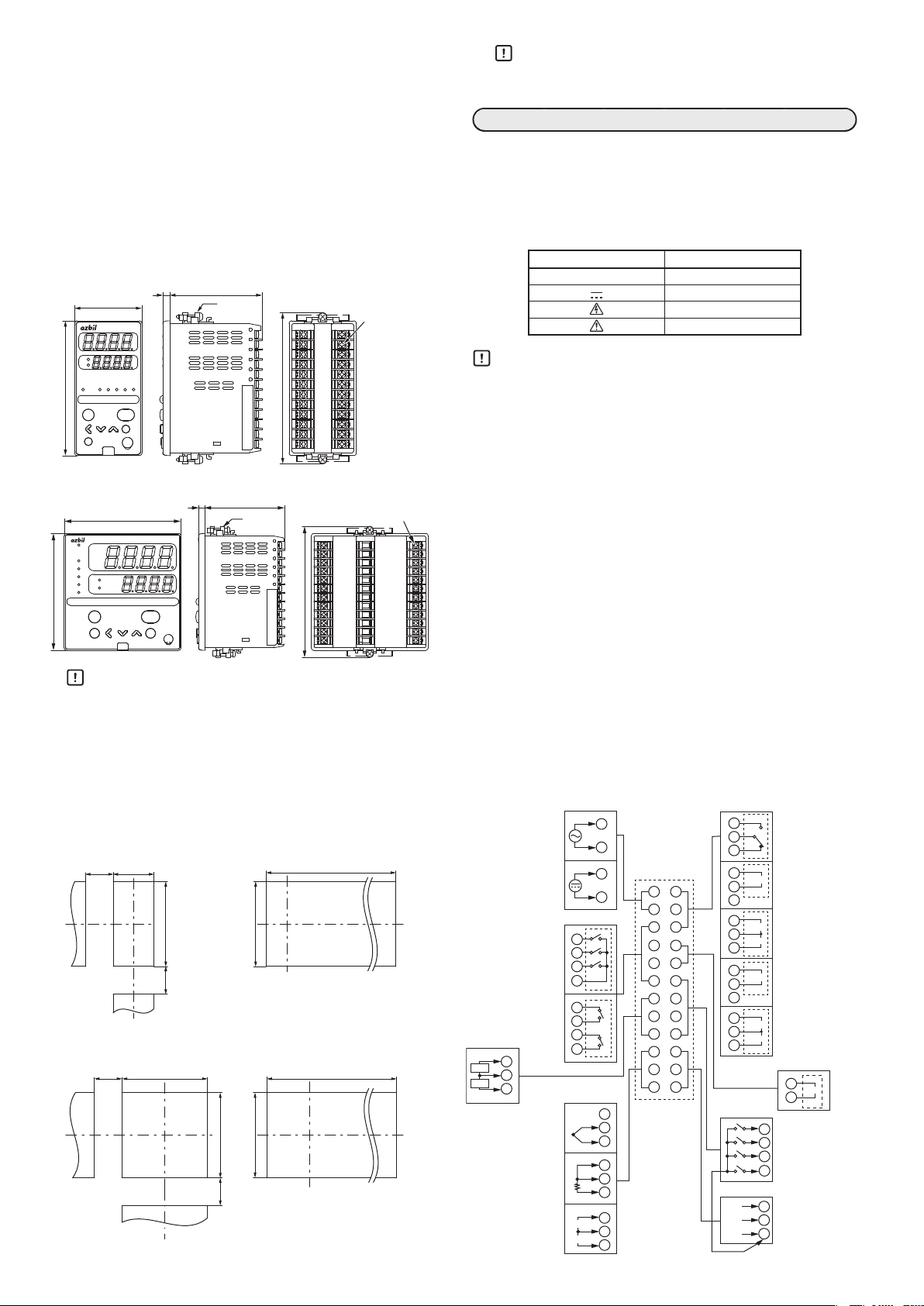
各部の名称と機能
SDC25
pv
sp
out
man ev1 ev2 ev3 ot1 ot2
display
mode
enter
para
②
③
⑥
⑨
⑩
man
pv
ev1
ev2
ev3
sp
ot1
out
ot2
④
⑤
mode
para
①第 1 表示部 :PV値(現在の温度など)や設定項目を表示します。
②第 2 表示部 :SP値(設定温度など)や各設定項目の設定値を表示
します。第2表示部がSPを表示しているときは、
spが点灯し、操作量(MV)を表示しているときは、
outが点灯します。
③モード表示灯
man :MANUAL モード(手動)のとき点灯します。
ev1 〜 ev3 :イベントリレー出力がONしているとき点灯します。
ot1・ot2 :制御出力が ON しているとき点灯します。
④MS(マルチステータス)表示灯
:点灯条件と点灯状態を組みにして、優先度のついた
3組を設定できます。
⑤[mode]キー :1秒以上押し続けると、あらかじめ設定してある操
作ができます。
⑥[display]キー:運転表示で表示内容を切り替えます。バンク設定表
示から運転表示に戻します。
⑦
[<]、[∨]、[∧]キー
:数値の増減、桁送りに使用します。
⑧[para]キー :表示の切り替えをします。
⑨[enter]キー :設定の変更開始と変更中の数値の確定を行います。
⑩
ローダコネクタ
:スマートローダパッケージに同梱されている専用
ケーブルを使用してパソコンと接続します。
SDC26
display
enter
設 置
■ 取付場所
本器を取り付けるときは、次のような場所に設置してください。
•供給電源およびリレー接点出力を除く入出力のコモンモード
電圧:対大地間の電圧は、30Vr.m.s.以下、42.4V ピーク以
下、DC60V以下としてください。
•高温、低温、高湿度、低湿度にならない
•硫化ガスなど腐食性ガスやシリコーンガスのない
•粉じん、油煙などの少ない
場所
•直射日光および風雨の当たらないように適切な処理のされ
た
場所
•機械的振動、衝撃の少ない
場所
場所
場所
Page 2
•高圧線の下、溶接機の近くおよび電気的ノイズの発生源の
端子ねじ M3
5
65
96
65
5
96
密着取付個別取付
密着取付個別取付
電 源
電 流
制御出力
近くでない
•ボイラなどのような高圧点火装置から15m以上離れた
•電磁界の影響の少ない
•可燃性の液体や蒸気のない
場所
場所
場所
場所
取り扱い上の注意
3台以上密着して取り付ける場合は、周囲温度は40 ℃を
•
超えないようにしてください。
結 線
•屋内
すべての配線作業は、それぞれの地域の規則に従って、認定された経
■ 取付方法
•取付角度は水平位置から、後下がり10度以内、後上がり 10
度以内としてください。
•パネルは板厚9 mm 以下で剛性のあるものをご使用ください。
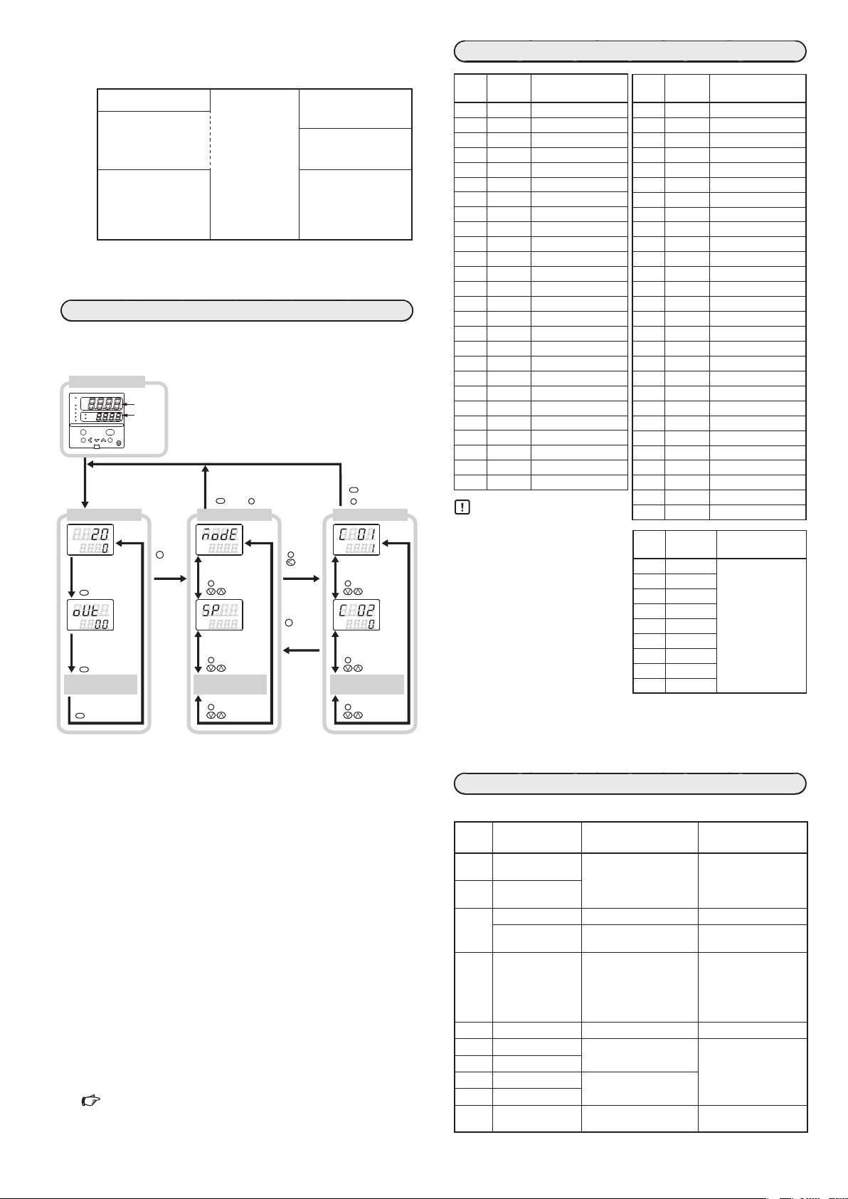
■ 外形寸法
● C25
pv
out
● C26
man
ev1
ev2
ev3
ot1
ot2
48
SDC25
sp
ot2ot1ev3ev2ev1man
display
mode
enter
para
96
pv
sp
out
mode
para
SDC26
display
enter
取付器具
(付属品)
取付器具
(付属品)
108
108
単位:mm
端子ねじ M3
験のある作業者が行ってください。本器を操作される方の手が届く範
囲内に、本器の主電源遮断用のスイッチを必ず設けてください。
また、AC電源モデルの本器の電源配線には遅動タイプ(T)の定格電
流0.5A、定格電圧250Vのヒューズを設けてください。(IEC127)
本器側面の端子配列ラベルで使用している記号の意味は下表のとおり
です。
記 号 内 容
〜
交 流
直 流
注意、感電の危険
注 意
取り扱い上の注意
結線は本器の形番と端
•
から行い、必ず間違いのないことを確認してください。
端子の接続にはM3のねじに適合する圧着端子を使ってください。
•
入出力信号線は動力線や電源線から50 cm以上離してください。
•
また、同一の配線管やダクト内を通さないでください。
圧着端子などが隣の端子と接触しないようにしてください。
•
一つの端子ねじに複数の圧着端子を配線する場合は、あらかじ
•
め圧着端子を曲げ、2枚までの接続としてください。
本器の電源がOFFのときは電流入力回路が切断されます。複
•
数台の電流入力を直列計装し、本器の電源を個別にON/OFF
させたい場合は、別売の抵抗(81401325)をつけて電圧入力レ
ンジで受けてください。
カレントトランスにはヒータ電流の流れる導線を貫通させてく
•
ださい。また、ヒータ電流は仕様に記載した許容電流を超えて
使用しないでください。本器を破損することがあります。
カレントトランス入力は位相制御に使用できません。
•
制御出力1と制御出力2の間は絶縁されていません。必要に応じ
•
子番号を本体側面のラベルで確認して
てアイソレータを使用してください。
RS-485の伝送路の両端に終端抵抗をつけないでください。通
•
取り扱い上の注意
付属の取付器具のねじを締めて、取付器具が動かなくなっ
•
たガタのない状態からさらに半回転だけねじを回してパネ
ルに固定してください。
ねじを締めすぎるとケースが変形するおそれがあります。
本器を操作される方が背面端子に触らないように、必ずパ
•
ネルに取り付けてください。
■ パネル穴あけ図
単位:mm
● C25
30以上
44
+0.5
0
+0.5
0
92
30
以上
+0.5
0
92
(48×N-4)
+0.5
0
● C26
30以上
+0.5
92
0
+0.5
0
92
30
以上
+0.5
(96×N-4)
0
92
+0.5
0
信できなくなります。
本器に接続する機器または装置は、本器の電源、入出力部の最
•
高使用電圧に適した強化絶縁が施されているものを使用してく
ださい。
本器は電源投入後、安定のため最大5秒間は機能しないように
•
なっています。その後運転状態に入りますが、規定の精度を満
足させるためには、ウォームアップ時間が30分以上必要です。
● 結 線
COM
DA
DB
SG
13
14
15
13
14
13
14
15
13
14
13
14
15
DI
4
3
2
1
通 信
+
-
+
1
-
+
2
+
-
+
1
-
2
+
18
19
20
21
22
23
24
AC電源
AC100~240 V
DC電源
AC24 V/DC24 V
(無極性)
独立接点
CT入力
7
CT1
8
CT2
9
測温抵抗体
直流電流
直流電圧
リレ ー
リレ ー
熱電対
1
2
1
2
イ ベ ント 出 力
3
3
2
4
1
5
COM
6
3
2
4
5
1
6
PV入力
-
+
C
B
A
+
mA
-
V
+
1
13
2
14
3
15
4
16
5
17
6
18
7
19
8
20
9
21
10
22
11
23
12
24
10
11
12
10
11
12
10
11
12
リレ ー
電圧パルス
電圧パルス
電圧パルス
電 流
電 流
電 流
補助出力
16
+
-
17
デジタル 入力
RS-485
J2
Page 3
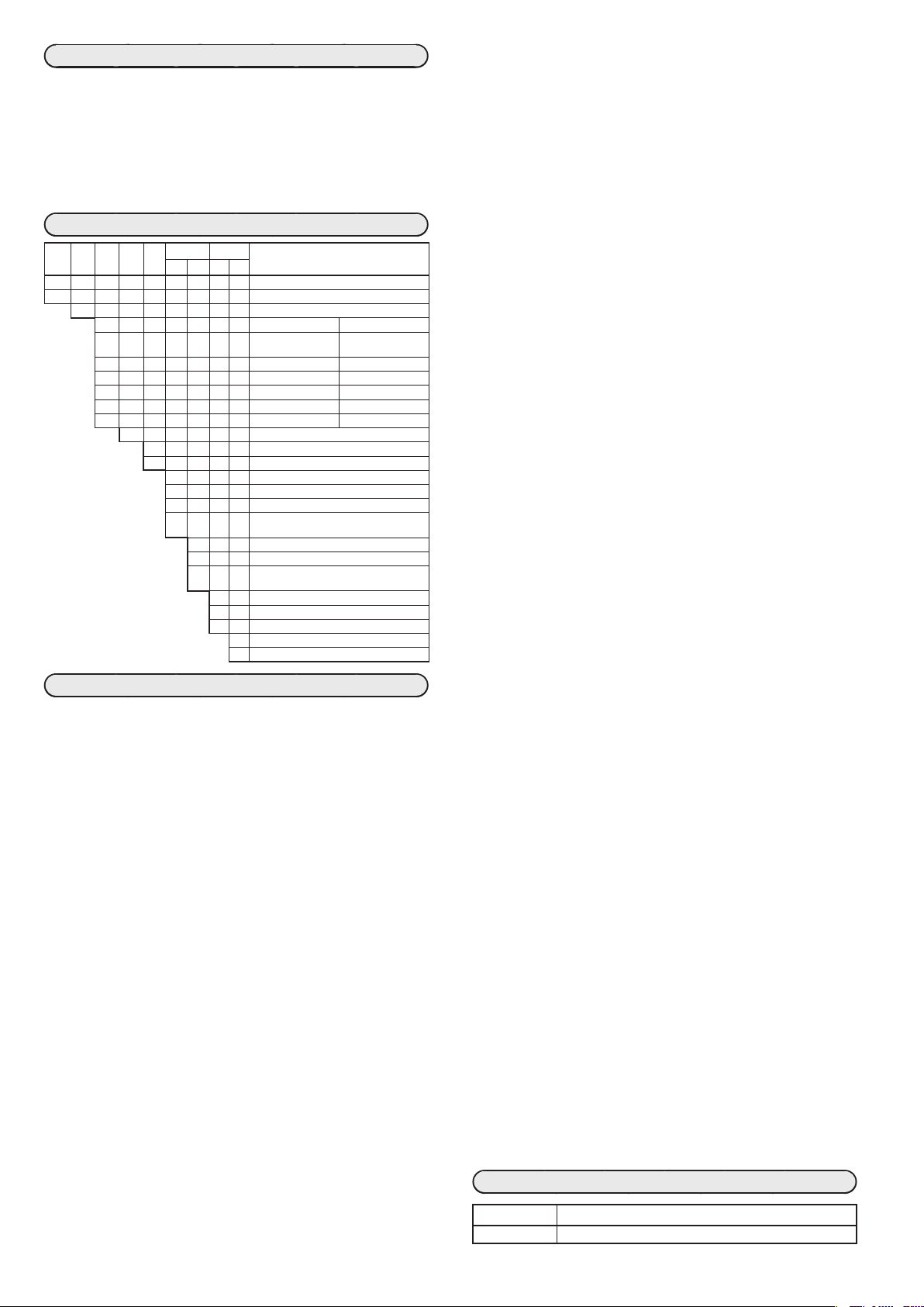
キー操作のフローを示します。
電源投入時表示
データの設定方法には、標準タイプと特殊タイプがあります。
ここでは標準タイプで説明しています。
man
ev1
ev2
ev3
ot1
ot2
その他の表示・設定
(displayキー操作の繰り返し)
display
この図に書いてある表示や設定の状態は、説明のための例です。
実際には形番や設定内容により表示しない表示や設定があります。
バンク設定表示のC0 1はバンク選択がセットアップバンクのときに表示します。
● 入出力間アイソレーション
実線で囲まれたものは他の信号と絶縁されています。入出力
の有無は形番によります。
電 源
PV入力
CT入力1
CT入力2
ローダ通信
内部回路
デジタル入力1
デジタル入力2
デジタル入力3
デジタル入力4
RS-485通信
*
独立接点の場合、イベント出力 1 とイベント出力 2 の間は
制御出力1
制御出力2
補助出力
イベント出力1
イベント出力2
イベント出力3
*
*
絶縁されています。
設定操作
SDC26
pv
sp
out
mode
para
運転表示 バンク選択表示 バンク設定表示
PV/SP表示
display
キーを 押す
MV表示
display
キーを 押す
キーを 押す
[∨][∧]キーを押してセットアップバンク
[enter]キーを押してください。次に[∨][∧]キーを押して第
[enter]キーを押すと、第2表示部がフラッシング(点滅)します。
[<][∨][∧]キーで桁の移動や値の増減をしてください。
[∨][∧]キーを押して SP バンクSPを表示させ、[enter]キー
[enter]キーを押すと、第2表示部がフラッシング(点滅)します。
[<][∨][∧]キーで桁の移動や値の増減をしてください。
取り扱い方法、設定方法の詳細は、別冊の
消 灯
消 灯
display
enter
電源投入後 5~6 秒 の間は、第1表示部・第2表示部
が 消 灯 の ま ま 、モ ー ド 表 示 灯 が 順 に 点 灯 し て い き ま す 。
すべてが点灯すると、運転表示に切り替わります。
3分以上
キーを 押さない
display
mode
PVレンジ種類設定
para
温度単位設定
para
その他の設定
(para、∨、∨キー操作の繰り返し)
para
para
キーを
2秒以上
押す
3分以上キーを押さない
display
mode
または キーを押す
モ ード バ ン ク 選 択
para
キーを 押す
キーを 押す
SPバンク選択
para
キーを 押す
キーを 押す
その他のバンク
(para、∨、∨キー操作の繰り返し)
para
キーを 押す
キーを 押す
各 バンク
選択表示で
enter
または
キーを
押す
para
キーを
2秒以上
押す
または
キーを 押す
キーを 押す
キーを 押す
キーを 押す
キーを 押す
キーを 押す
キーを 押す
● PVレンジ種類の設定例
バンク選択表示がモードバンク選択
1表示部にC01を表示させてください。
希望の数値で[enter]キーを押すと、フラッシングが終了し、
データが確定します。
MOdE
のときに
Stup
を表示させ、
● SP1の設定例
バンク選択表示がモードバンク選択
を押してください。次に[∨][∧]キーを押して第 1 表示部に
SP-1
を表示させてください。
希望の数値で[enter]キーを押すと、フラッシングが終了し、
データが確定します。
デジタル指示調節計SDC25/26 詳細編 CP-SP-1149
または、デジタル指示調節計 SDC25/26 キー操作ダイジェ
スト CP-SP-1217 をご覧ください。
MOdE
のときに
PVレンジ表
C0 1�
入力タイプ レンジ
設定値
1 K -200〜+1200 ℃
2 K 0〜1200 ℃
3 K 0.0〜800.0 ℃
4 K 0.0〜600.0 ℃
5 K 0.0〜400.0 ℃
6 K -200.0〜+400.0 ℃
7 K -200.0〜+200.0 ℃
8 J 0〜1200 ℃
9 J 0.0〜800.0 ℃
10 J 0.0〜600.0 ℃
11 J -200.0〜+400.0 ℃
12 E 0.0〜800.0 ℃
13 E 0.0〜600.0 ℃
14 T -200.0〜+400.0 ℃
15 R 0〜1600 ℃
16 S 0〜1600 ℃
17 B 0〜1800 ℃
18 N 0〜1300 ℃
19 PL II 0〜1300 ℃
20 WRe5-26 0〜1400 ℃
21 WRe5-26 0〜2300 ℃
22 Ni-Ni・Mo 0〜1300 ℃
23 PR40-20 0〜1900 ℃
24 DIN U -200.0〜+400.0 ℃
25 DIN L -100.0〜+800.0 ℃
26
金鉄クロメル
0.0K〜360.0K
取り扱い上の注意
精度はレンジにより異なります。
•
No.17(センサタイプB)は、
•
260 ℃以下:±4.0 %FS、
260 〜 800 ℃:± 0.4 %FS
20 ℃未満は表示されません。
No.23(センサタイプPR40-20)
は、0 〜 300 ℃:± 2.5 %FS、
300 〜 800 ℃:± 1.5 %FS、
800 〜 1900 ℃:± 0.5 %FS。
No.26(センサタイプ金鉄クロ
メル)は、±2.0 Kとなります。
小数点表示のあるレンジは、
•
小数点以下一桁表示ができます。
使用するセンサのタイプとレンジのC0 1設定値を正しく設定し
•
てください。大きな温度誤差などで異常な出力をする場合があ
ります。
アラームコード一覧表
本器異常時のアラーム表示と対策を示します。
J3
アラーム
コード
AL0 1
AL02
AL03
AL 1 1
AL70
AL95
AL96
AL97
AL98
AL99
*1
異常名称 原 因 処 置
PV入力異常
(オーバーレンジ)
PV入力異常
(アンダーレンジ)
CJ異常 • 端子温度異常(熱電対) • 周囲温度の確認
PV入力異常 • センサ断線
CT入力異常
(オーバーレンジ)
(CT入力1/2 の
片方または両方)
A/D変換異常 • A/D変換部故障 • 本体交換
パラメータ異常
調整データ異常
パラメータ異常
調整データ異常
ROM異常 • ROM(メモリ)故障 • 電源再投入
AL95/97
は設定データ、
• センサ断線
• 誤配線
• PVレンジ種類誤設定
• 誤配線(測温抵抗体)
• 表示範囲上限を超える電
流を測定
• CTターン数誤設定
• CT電力線貫通回数誤設定
• 誤配線
• データ確定中に電
• ノイズなどでデータ破壊
*2
• ノイズなどでデータ破壊
*2
AL96/98
C0 1�
入力タイプ レンジ
設定値
41 Pt100 -200.0〜+500.0 ℃
42 JPt100 -200.0〜+500.0 ℃
43 Pt100 -200.0〜+200.0 ℃
44 JPt100 -200.0〜+200.0 ℃
45 Pt100 -100.0〜+300.0 ℃
46 JPt100 -100.0〜+300.0 ℃
47 Pt100 -100.0〜+200.0 ℃
48 JPt100 -100.0〜+200.0 ℃
49 Pt100 -100.0〜+150.0 ℃
50 JPt100 -100.0〜+150.0 ℃
51 Pt100 -50.0〜+200.0 ℃
52 JPt100 -50.0〜+200.0 ℃
53 Pt100 -50.0〜+100.0 ℃
54 JPt100 -50.0〜+100.0 ℃
55 Pt100 -60.0〜+40.0 ℃
56 JPt100 -60.0〜+40.0 ℃
57 Pt100 -40.0〜+60.0 ℃
58 JPt100 -40.0〜+60.0 ℃
59 Pt100 -10.00〜+60.00 ℃
60 JPt100 -10.00〜+60.00 ℃
61 Pt100 0.0〜100.0 ℃
62 JPt100 0.0〜100.0 ℃
63 Pt100 0.0〜200.0 ℃
64 JPt100 0.0〜200.0 ℃
65 Pt100 0.0〜300.0 ℃
66 JPt100 0.0〜300.0 ℃
67 Pt100 0.0〜500.0 ℃
68 JPt100 0.0〜500.0 ℃
C0 1�
入力タイプ レンジ
設定値
81 0〜10 mV -1999〜+9999の
-10〜+10 m V
82
83 0〜100 mV
範囲でスケーリング
小数点位置可変
84 0〜1 V
86 1〜5 V
87 0〜5 V
88 0〜10 V
89 0〜20 mA
90 4〜20 mA
• 配線の確認
• PVレンジ種類の再設定
• 配線の確認
• 表示範囲に合ったター
ン数のCT使用
• CTターン数の再設定
• CT電力線貫通回数の再
設定
• 配線の確認
源断
• 電源再投入
• データの再設定
• 本体交換
• 本体交換
は調整データ *2 RAM領域
*1
Page 4
保 守
清 掃 : 本器の汚れを取る場合は、柔らかい布での乾拭きを
行ってください。シンナー、ベンゼンなどの有機溶剤
や洗剤は使用しないでください。
部品交換 :部品交換は、おやめください。
ヒューズ交換: AC 電源モデルで電源配線に設けたヒューズを交換す
るときは、必ず指定の規格品を使用してください。
規格 IEC127、遮断速度 遅動タイプ(T)、
定格電圧 250V、定格電流 0.5A
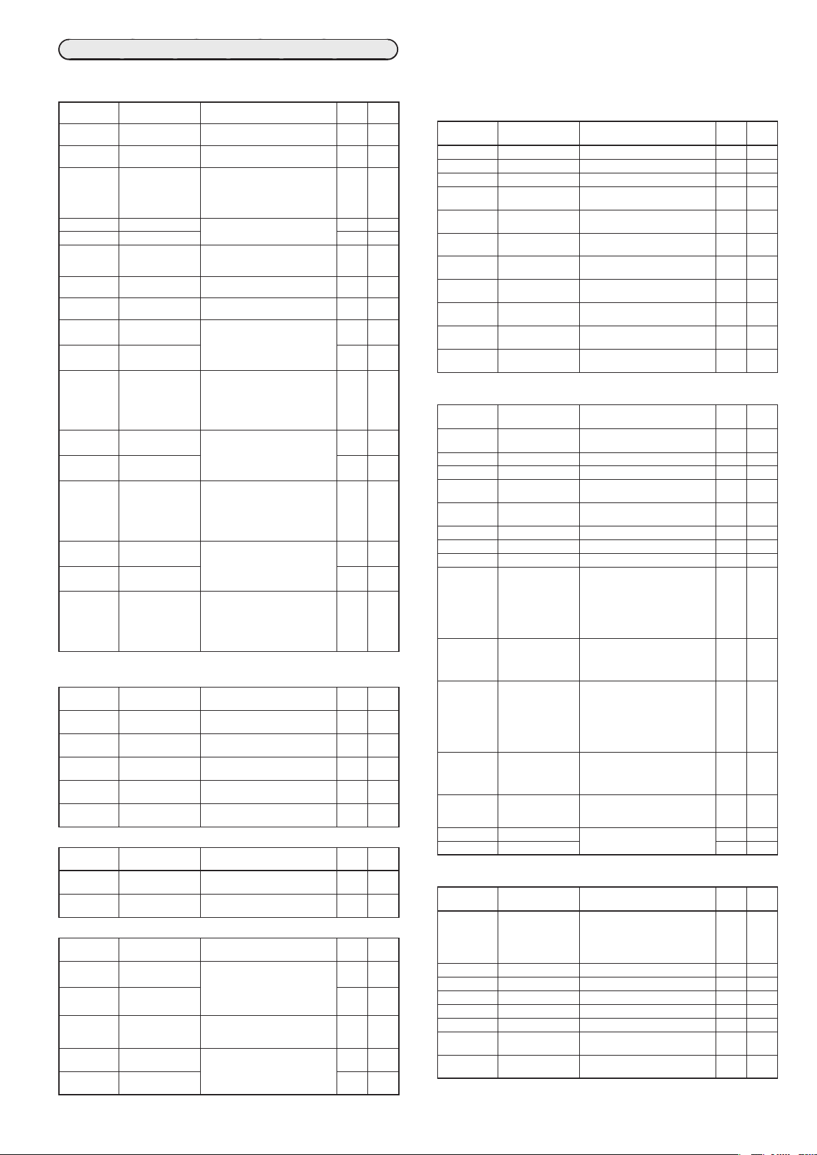
形番構成表
基本形番取り 付け制御出力PV入力電源 オ プシ ョン 追加処理 仕 様
1 2
C25 マスクサイズ48 mm× 96 mm
C26 マスクサイズ96 mm× 96 mm
T パネル取付形
R0 リレー出力 NO なし(制御出力 1の
V0 電圧パルス出力
VC 電圧パルス出力
VV 電圧パルス出力
C0 電流出力 なし
CC 電流出力 電流出力
U ユニバーサル
A AC電源(AC100 〜 240 V)
D DC電源(AC24 V/DC24 V)
*2
*2
*3
*3
*
1 SSR駆動用
*
2 D C 電源では選 択できません
*
3 カレントトランスは別売です
1 2
制御出力1 制御出力2
リレー出力 NC)
*1
*1
*1
1
2
4 イベントリレー出力 2点(独立接点)
5 イベントリレー出力 2点(独立接点)、
0 なし
1
2
イベントリレー出力3点
イベントリレー出力3 点、補助出力(電流出力)
補助出力(電流出力)
カレントトランス入力2点、デジタル入力4点
カレントトランス入力2 点、デジタル入力4 点、
RS-485通信
0 追加処理なし
D 検査成績書添付
Y トレーサビリティ証明対応
0 なし
A UL 対応品
なし
電流出力
電圧パルス出力
仕 様
zPV入力
熱電対 :K、J、E、T、R、S、B、N(JISC1602-1995)
測温抵抗体 :
直流電圧 :0〜10mV、-10〜+10mV、0〜100mV、0〜
直流電流 :0〜20mA、4〜20mA
サン プリング 周期
指示精度 :±0.3%FS±1digit
許容入力 :•-0.5〜+12V(熱電対、測温抵抗体、直流電圧)
zデジタル入力
点 数 :4点
入力形式
許容ON接点抵抗:250Ω以下
許容OFF接点抵抗:100kΩ以上
許容ON残留電圧:1.0V以下
ON時端子電流
最小ホールド時間:600ms以上
zカレントトランス入力
点 数 :2点
入力対象 :カレントトランス 巻数100 〜 4000ターン
計測電流下限 :AC0.4A(800ターン、電力線貫通回数1にて)
計測電流上限 :AC50.0A(800ターン、電力線貫通回数1にて)
PLⅡ(EngelhardIndustries 資料(ITS90))
WRe5-26(ASTME988-96(Reapproved2002))
Ni-Ni・Mo(ASTME1751-00)
PR40-20(JohnsonMatthey 資料)
DINU、DINL(DIN43710-1985)
金鉄クロメル(林電工資料)
Pt100(JISC1604-1997)、JPt100(JISC1604-1989)
1V、1〜5V、0〜5V、0〜10V
:300ms
熱電対の負の領域は±0.6
%FS±1digit(周囲温
度23±2℃にて)
•30mA以下または 4V 以下(直流電流)
許容入力値以上の電圧または電流が入力される
と破損することがあります。
:
無電圧接点またはオープンコレクタ
:
約7.5mA(短絡時)、約5.0mA(接点抵抗250Ω時)
(100ターン単位で対応)
計算式(ターン数÷(2000×電力線貫通回数))
計算式(ターン数÷(16×電力線貫通回数))
許容計測電流 :
AC70.0A以下(800ターン、電力線貫通回数 1 にて)
計算式(ターン数÷(16×電力線貫通回数)×1.4)
表示範囲下限 :AC0.0A
表示範囲上限 :AC70.0A(800ターン、電力線貫通回数1にて)
計算式(ターン数÷(16×電力線貫通回数)×1.4)
表示精度 :±5%FS
表示分解能 :AC0.1A
z制御出力
•リレー出力
接点定格 :
制御出力1NO側AC250V/DC30V、3A(抵抗負荷)
制御出力2NC側AC250V/DC30V、1A(抵抗負荷)
寿 命 :NO側5万回以上、NC側10万回以上
最小開閉仕様 :5V、100mA
最小開時間/閉時間
:250ms
•電圧パルス出力(SSR駆動用)
開放時端子間電圧
:DC19V±15%
内部抵抗 :82Ω± 0.5%
許容電流 :DC24mA 以下(これ以上の電流を出力すると出力
回路を破壊することがあります)
最小OFF時間/
*1
ON時間
•電流出力
:時間比例周期10s未満のとき1ms
時間比例周期10s以上のとき250ms
出力形式 :DC0 〜 20mAまたは4 〜 20mA電流出力
許容負荷抵抗 :600Ω以下
出力精度 :±0.3%FS(周囲温度23±2℃にて)
ただし0〜1mAは±1%FS
z補助出力
出力形式 :DC0 〜 20mA または 4 〜 20mA 電流出力
許容負荷抵抗 :600Ω以下
出力精度 :±0.3%FS(周囲温度23±2℃にて)
ただし0 〜 1mAは± 1%FS
zイベントリレー出力(ev1 〜 ev3)
接点定格 :AC250V/DC30V2A(抵抗負荷)
寿 命 :10万回以上
最小開閉仕様 :5V、10mA(参考値)
zRS-485通信
伝送路 :3線式
伝送速度 :4800、9600、19200、38400bps
通信プ ロトコル :CPL、Modbus準拠
終端抵抗 :接続禁止
z環境条件
•動作条件
周囲温度 :0 〜 50℃(密着取付の場合は 0 〜 40℃)
周囲湿度 :10 〜 90%RH(結露なきこと)
定格電源電圧 :AC電源モデル AC100 〜 240V50/60Hz
DC電源モデル AC24V50/60Hz、DC24V
電源電圧範囲 :AC電源モデル AC85 〜 264V、50/60± 2Hz
DC電源モデル AC21.6 〜 26.4V50/60±2Hz、
DC21.6 〜 26.4V
•輸送条件
周囲温度 :-20 〜+ 70℃
周囲湿度 :10 〜 95% RH(結露なきこと)
zその他仕様
消費電力 :AC電源モデル 12VA以下
DC電源モデル 12VA以下(AC24V)
8W 以下(DC24V)
停電不感時間 :AC電源モデル 20ms以下
DC電源モデル 停電なきこと
高 度 :2000m以下
質 量 :C2548×96 約250g(専用取付器具を含む)
C2696×96 約300g(専用取付器具を含む)
端子ねじ締付トルク
:0.4〜0.6N・m
適合規格 :EN61010-1、
EN61326-1(Foruseinindustriallocations)
EMC試験中、±10%FSに相当する指示値や出力
値の変動が生じる場合があります。
過電圧カテゴリ:CategoryⅡ(IEC60364-4-443、IEC60664-1)
許容汚染度 :Pollutiondegree2
付属品一覧表
名 称 形 番
取付器具 81409654-001(付属品)
J4
Page 5
SDC25/26パラメータ一覧表
【運転表示一覧表】
■運転表示
表 示 項 目 内 容 初期値 表 示
第1表示:PV
第2表示:SP
LSP 1
第2表示:LSP
第1表示:PV
第2表示:MV
HEAt
COOL
第1表示:PV
(表示例)
At 1
Ct 1
Ct2
E 1
E 1.Sb
t 1.--�
(表示例)
E2
E2.Sb
t2.--�
(表示例)
E3
E3.Sb
t3.--�
(表示例)
SP(目標値) S P リ ミ ッ ト 下 限(
LSP組番号
(表示例)
(第1 桁=最右桁の数値)
MV(操作量) -10.0 〜+110.0 %
加熱MV(操作量) 設定不可
冷却MV(操作量) — 0
AT進捗
(第1 桁=最右桁の数値)
C T( カ レ ン ト ト ラ ン ス )
入力1電流値
C T( カ レ ン ト ト ラ ン ス )
入力2電流値
内部イベント1 主設定
内部イベント1 副設定 0 0
タイマ残り時間1 設定不可
内部イベント2 主設定
内部イベント2 副設定 0 0
タイマ残り時間2 設定不可
内部イベント3 主設定
内部イベント3 副設定 0 0
タイマ残り時間3 設定不可
C08
上 限(
1 〜 LSP使用組数(
AUTOモードで設定不可
(数値の点滅なし)
MANUALモードで設定可能
(数値の点滅あり)
-10.0 〜+ 110.0 %
設定不可
1 〜 :AT起動中(値が減っていく)
0 :AT 終了
設定不可 — 0
設定不可 — 0
内部イベント動作種類により設定可能
な範囲が異なる
-1999
〜
9999U:設定値が絶対値の場合
0
-199.9
第1表示:「t 1.」の横に ONディレイ、
OFFディレイの区別を表示
第2表示:内部イベント 1ディレイ
時間単位(E
単位(0.1s、s、minのどれか)で表示
内部イベント動作種類により設定可能
な範囲が異なる
-1999
〜
9999U:設定値が絶対値の場合
0
-199.9
第1表示:「
OFFディレイの区別を表示
第2表示:内部イベント 2ディレイ
時間単位(
単位(0.1s、s、minのどれか)で表示
内部イベント動作種類により設定可能
な範囲が異なる
-1999
〜
9999U:設定値が絶対値の場合
0
-199.9
第1表示:「
OFFディレイの区別を表示
第2表示:内部イベント 3 ディレイ
時間単位(
単位(0.1 s、s、minのどれか)で表示
【パラメータ設定表示一覧表】
■モードバンク:
表 示 項 目 内 容 初期値 表 示
A--M
r--r
At
dO.Lt
C.dI 1
■SP バンク:
表 示 項 目 内 容 初期値 表 示
〜
SP- 1
SP-4
〜
PId. 1
PId.4
■イベントバンク:
表 示 項 目 内 容 初期値 表 示
E 1〜E5
〜
E 1.Sb
E5.Sb
〜
E 1.Hy
E5.Hy
〜
E 1.On
E5.On
〜
E 1.OF
E5.OF
MOdE
AUTO/MANUAL
モード切り替え
RUN/READYモード
切り替え
AT停止/ 起動
切り替え
全DOラッチ解除
通信DI1
AUTO
:AUTO(自動)モード
MAN
:MANUAL(手動)モード
RUN
:RUNモード
RDY
:READYモード
At.OF
At.ON
Lt.ON
:ラッチ継続
Lt.OF
:ラッチ解除
dI .OF
dI .On
SP
LSP1〜4組のSP SPリミット下限(
PID組番号
(LSP1〜4用)
C08
上 限(
1〜4 1 1
Ev
内部イベント1〜5
主設定
内部イベント1〜5
副設定
内部イベント1〜5
ヒステリシス
内部イベント1〜5
ONディレイ
内部イベント1〜5
OFFディレイ
-1999〜+9999
小数点位置は内部イベント動作種類
に合うように変わります
一部の動作種類では、0〜9999とな
ります
0〜9999
小数点位置は内部イベント動作種類
に合うように変わります
0.0 〜 999.9(ディレイ時間単位
0.1 sの場合)
0 〜 9999(ディレイ時間単位 0.1 s
以外の場合)
C07
)
〜
〜
〜
〜
〜
〜
:AT 停止
:AT 起動
:OFF
:ON
)
)〜 S P リ ミ ッ ト
C30
、最大4) 1 0
+9999U:下記以外の場合
+999.9 %:MVの場合
1.C3
の3桁目)に従った
+9999U:下記以外の場合
+999.9 %:MVの場合
t2.
」の横に ONディレイ、
E2.C3
の3桁目)に従った
+9999U:下記以外の場合
+999.9 %:MVの場合
t3.
」の横に ONディレイ、
E3.C3
の3桁目)に従った
C07
)〜SPリミット
レベル
0 0
— 0
— 0
— 0
0 0
— 0
0 0
— 0
0 0
— 0
レベル
AUTO 0
RUN 0
AT停止 0
ラッチ継続0
OFF 0
レベル
0 0
レベル
0 0
0 0
5 0
0 2
0 2
表示レベルの意味 0:簡単・標準・多機能で表示、
1:標準・多機能で表示、
2:多機能で表示
初期値は形番により変わるものがあります。
■PID バンク:PI
表 示 項 目 内 容 初期値 表 示
P- 1〜P-4
I - 1〜I -4
d- 1〜d-4
〜
rE- 1
rE-4
OL- 1〜OL-4
〜
OH- 1
OH-4
〜
P- 1C
P-4C
〜
I - 1C
I -4C
〜
d- 1C
d-4C
OL. 1C
〜
OL.4C
OH. 1C
〜
OH.4C
■パラメータバンク:
表 示 項 目 内 容 初期値 表 示
CtrL
At.OL
At.OH
dI FF
OFFS
FL
rA
bI
CyU
Cy
CyU2
Cy2
tP.ty
SPU
SPd
■拡張調整バンク:
表 示 項 目 内 容 初期値 表 示
At.ty
JF.bd
SP.LG
At-P
At-I
At-d
Ctr.A
JF.Ov
d
比例帯(PID1 〜 4 組)0.1 〜 999.9 % 5.0 0
積分時間(PID1〜 4 組)
微分時間(PID1〜 4 組)
マニュアルリセット
(PID1 〜 4組)
操作量下限
(PID1 〜 4組)
操作量上限
(PID1 〜 4組)
冷却側比例帯
(PID1 〜 4組)
冷却側積分時間
(PID1 〜 4組)
冷却側微分時間
(PID1 〜 4組)
冷却側操作量下限
(PID1 〜 4組)
冷却側操作量上限
(PID1 〜 4組)
0 〜 9999 s(0 で積分動作なし) 120 0
0 〜 9999 s(0 で微分動作なし) 30 0
-10.0 〜+ 110.0 % 50.0 0
-10.0 〜+ 110.0 % 0.0 1
-10.0 〜+ 110.0 % 100.0 1
0.1 〜 999.9 % 5.0 0
0 〜 9999 s(0 で積分動作なし) 120 0
0 〜 9999 s(0 で微分動作なし) 30 0
-10.0 〜+ 110.0 % 0.0 1
-10.0 〜+ 110.0 % 100.0 1
PArA
制御方式 0:ON/OFF 制御
AT時操作量下限 - 10.0 〜+110.0 % 0.0 0
AT時操作量上限 - 10.0 〜+110.0 % 100.0 0
ON/OFF制御
ディファレンシャル
ON/OFF制御
動作点オフセット
PVフィルタ 0.0 〜 120.0 s 0.0 0
PVレシオ 0.001 〜 9.999 1.000 1
PVバイアス - 1999 〜+9999 U 0 0
時間比例単位1 0:1 s 単位
時間比例周期1 5 〜 120 s
時間比例単位2 0:1 s 単位
時間比例周期2 5 〜 120 s
時間比例動作種類 0: 制御性重視型
SPランプ上昇勾配 0.0 〜 999.9 U
SPランプ下降勾配 0.0 2
1:PID固定
0 〜 9999 U 5 0
-1999 〜+ 9999 U 0 2
1: 0.5 s固定
(サイクルタイム設定不可)
2: 0.25 s固定
(サイクルタイム設定不可)
3: 0.1 s固定
(サイクルタイム設定不可)
(出力にリレー出力を含む場合)
1 〜 120 s
(出力にリレー出力を含まない場合)
1: 0.5 s固定
(サイクルタイム設定不可)
2: 0.25 s固定
(サイクルタイム設定不可)
3: 0.1 s固定
(サイクルタイム設定不可)
(出力にリレー出力を含む場合)
1 〜 120 s
(出力にリレー出力を含まない場合)
操作端寿命重視型(時間比例周期
1 :
内では1回だけのON/OFF動作)
(0.0 Uは勾配なし)
または1
10
または
10
または
または
0.0 2
Et
AT種類 0: 通常(標準的な制御特性)
JF整定幅 0.00 〜 10.00 0.30 2
SPラグ定数 0.0 〜 999.9 0.0 2
AT時比例帯調整係数 0.00 〜 99.99 1.00 2
AT時積分時間調整係数
AT時微分時間調整係数
制御アルゴリズム 0:PID(従来型PID)
JFオーバーシュート
抑制係数
1: 即応(外乱に速やかに反応する
制御特性)
2: 安定(PV の上下動が少ない制御
特性)
0.00 〜 99.99 1.00 2
0.00 〜 99.99 1.00 2
1:Ra-PID(高性能型 PID)
0 〜 100 0 1
レベル
レベル
0
0 2
2
0 2
2
0
1
レベル
0 0
0 1
0
0
0
2
J5
Page 6

【セットアップ設定表示一覧表】
■セットアップバンク:
表 示 項 目 内 容 初期値 表 示
C 0 1
C 02
C 03
C 04
C 05
C 06
C 07
C 08
C 09
C 13
C 14
C 15
C 16
C 17
C 18
C 19
C 20
C 2 1
C 22
C 26
C 27
C 28
C 29
C 30
C 32
C 36
C 37
C 38
C 39
C 40
C 4 1
C 42
C 43
C 44
C 45
C 46
PVレンジ種類 熱電対のレンジ :1 〜 26
温度単位 0:摂氏(℃)
冷接点補償 0:冷接点補償を行う(内部)
小数点位置 0:小数点なし
PVレンジ下限 PVレンジ種類が熱電対、測温抵抗
PVレンジ上限 PVレンジ種類が熱電対、測温抵抗
SPリミット下限 PV レンジ下限〜 PVレンジ上限
SPリミット上限
開平演算
ドロップアウト
PID演算補正 0:有効
制御動作(正逆) 0:加熱制御(逆動作)
PV異常時操作量選択 0:制御演算を継続する
PV異常時操作量 - 10.0 〜+110.0 %
READY時操作量
(加熱冷却制御の場合
は加熱側)
READY時操作量
(冷却側)
MANUAL変更時動作 0:バンプレス
プリセットMANUAL値
PID演算初期化
機能選択
PID演算初期操作量 - 10.0 〜+110.0 %
加熱冷却制御選択 0:使用しない
加熱冷却切り替え 0:通常
加熱冷却制御不感帯 -100.0 〜+ 100.0 %
加熱冷却制御
切り替え点
LSP使用組数 1〜4
SPランプ単位 0:0.1 U/s
CT1動作 0:ヒータ断線検出
CT1監視出力 0:制御出力1
CT1測定待ち時間 30 〜 300 ms
CT2動作 0:ヒータ断線検出
CT2監視出力 0:制御出力1
CT2測定待ち時間 30 〜 300 ms
制御出力1レンジ 1:4 〜 20 mA
制御出力1種類 0:MV
制御出力1
スケーリング下限
制御出力1
スケーリング上限
制御出力1
MVスケーリング幅
StUP
測温抵抗体のレンジ :41 〜 68
直流電圧・直流電流のレンジ
:81 〜 84、86 〜 90
1:使用しないでください
1:冷接点補償を行わない(外部)
1:小数点以下1桁
2:小数点以下2桁
3: 小数点以下3桁
(熱電対/測温抵抗体の小数点付きレ
ンジの場合、0 〜 1)
体の場合、レンジの下限を表示する
が、設定不可
PVレンジ種類が直流電圧・直流電
流の場合、-1999 〜+ 9999 U
体の場合、レンジの上限を表示する
が、設定不可
PVレンジ種類が直流電圧・直流電
流の場合、-1999 〜+ 9999 U
0.0〜100.0 %(0.0で開平演算なし)
1:無効
1:冷却制御(正動作)
1:PV異常時操作量を出力する
10.0 〜+110.0 %
-
-10.0 〜+ 110.0 %
1:プリセット
-10.0 〜+ 110.0 %
(電源ON時に、MANUAL モードだっ
たときも使用する)
0:自動
1:初期化しない
2: 初期化する(現在値と異なる SP
値を入力したとき)
1:使用する
1:省エネ
-10.0 〜+ 110.0 %
1:0.1 U/min
2:0.1 U/h
1:電流値測定
1:制御出力2
2:イベント出力1
3:イベント出力2
4:イベント出力3
1:電流値測定
1:制御出力2
2:イベント出力1
3:イベント出力2
4:イベント出力3
2:0 〜 20 mA
1:加熱MV(加熱冷却制御用)
2:冷却MV(加熱冷却制御用)
3:PV
4:レシオ・バイアス・フィルタ前PV
5:SP
6:偏差(PV -SP)
7:CT1電流値
8:CT2電流値
9:MFB(C25/26 では無効)
10:SP+MV
11:PV+MV
-1999 〜+ 9999
(小数点位置と単位は、制御出力1 の
種類によって変わる)
0 〜 9999
(制御出力1種類が 10、11のとき有効)
レベル
88 0
0 0
0 2
0 0
0 0
1000 0
0 1
1000 1
0.0 2
0 2
0 0
0 2
0.0 2
0.0 1
0.0 1
0 1
0.0
または
50.0
0 2
0.0
または
50.0
0 0
0 1
0.0 0
50.0 2
1 0
1 2
0 0
0 0
30 0
0 0
0 0
30 0
1 0
0 0
0.0 0
100.0 0
200 0
表 示 項 目 内 容 初期値 表 示
C 47
C 48
C 49
C 50
C 5 1
C 52
C 53
C 54
C 55
C 56
C 64
C 65
C 66
C 67
C 68
C 69
C 70
C 7 1
C 72
C 73
1
2
C 74
C 75
C 76
C 77
C 78
C 79
C 80
制御出力2レンジ 制御出力 1と同じ
制御出力2種類
制御出力2
スケーリング下限
制御出力2
スケーリング上限
制御出力2
MVスケーリング幅
補助出力レンジ 制御出力1 と同じ
補助出力種類
補助出力
スケーリング下限
補助出力
スケーリング上限
補助出力
MVスケーリング幅
通信種類 0:CPL
機器アドレス 0 〜 127(0 のとき通信しない)
伝送速度 0:4800 bps
データ形式
(データ長)
データ形式
(パリティ)
データ形式
(ストップビット)
通信最小応答時間 1 〜 250 ms
キー操作種類 0:標準タイプ
modeキー機能 0:無効
モード表示設定 モードバンクの設定表示有無を下記
PV/SP値表示設定 基本表示の表示有無を下記の重み付
操作量表示設定 基本表示の表示有無を下記の重み付
イベント設定値
表示設定
イベント残り時間
表示設定
CT入力電流値
表示設定
表示レベル 0:簡単設定
LEDモニタ 0:使用しない
-1999 〜+ 9999
(小数点位置と単位は、制御出力2 の
種類によって変わる)
0 〜 9999
(制御出力2種類が 10、11 のとき有効)
-1999 〜+ 9999
(小数点位置と単位は、補助出力種
類によって変わる)
〜 9999
0
(補助出力種類が10、11のとき有効)
1:Modbus/ASCII形式
2:Modbus/RTU形式
1:9600 bps
2:19200 bps
3:38400 bps
ビット
0:7
1:8ビット
0:偶数パリティ
1:奇数パリティ
2:パリティなし
ビット
0:1
1:2ビット
1:特殊タイプ
1:AUTO/MANUAL切り替え
2:RUN/READY切り替え
3:AT停止/ 起動
4:LSP組切り替え
5:全DOラッチ解除
6:無効
7:通信DI1切り替え
8:無効
の重み付けの和で決める
ビット 0: AUTO/MANUAL表示
なし:0、あり:+ 1
ビット 1: RUN/READY表示
なし:0、あり:+ 2
ビット 3: AT停止/ 起動表示
なし:0、あり:+ 8
ビット 4: DOラッチ解除表示
なし:0、あり:+ 16
ビット 5: 通信DI1 ON/OFF表示
なし:0、あり:+ 32
その他 無効な設定
けの和で決める
ビット 0: PV表示
なし:0、あり:+ 1
ビット 1: SP表示
なし:0、あり:+ 2
ビット 2: LSP組番号表示
なし:0、あり:+ 4
その他無効な設定 0、+8
けの和で決める
ビット 0: MV表示
なし:0、あり:+ 1
ビット 1: 加熱MV/冷却 MV 表示
なし:0、あり:+ 2
ビット 3: AT進捗表示
なし:0、あり:+ 8
その他無効な設定 0、+4
0: 運転表示に内部イベント設定値
を表示しない
1: 運転表示に内部イベント1 設定値
を表示する
2: 運転表示に内部イベント1 〜 2
設定値を表示する
3: 運転表示に内部イベント1 〜 3
設定値を表示する
0 :
運転表示に内部イベントのON/OFF
ディレイ残り時間を表示しない
1 :
運転表示に内部イベント1の ON/
OFFディレイ残り時間を表示する
2: 運転表示に内部イベント1 〜 2
のON/OFFディレイ残り時間を
表示する
3: 運転表示に内部イベント1 〜 3
のON/OFFディレイ残り時間を
表示する
0 :
運転表示にCTの電流値を表示しない
1 :
運転表示にCT1電流値を表示する
2: 運転表示にCT1、CT2 電流値を
表示する
1:標準設定
2:多機能設定
1:RS-485通信送信時点滅
2:RS-485通信受信時点滅
3:全DI状態の OR(論理和)
4:READY時点滅
0、+4、+64、+ 128
レベル
1 0
3 0
0 0
1000 0
200 0
1 0
3 0
0 0
1000 0
200 0
0 0
0 0
2 0
1 0
0 0
0 0
3 2
0 2
1 0
255 1
15 1
15 1
0 1
0 1
0 1
1 0
0 2
J6
Page 7

表 示 項 目 内 容 初期値 表 示
C 8 1
C 82
C 83
C 84
C 85
C 86
C 87
C 88
C 89
C 90
C 9 1
C 92
C 93
C 97
MS表示灯点灯条件
(第1優先)
MS表示灯点灯状態
(第1優先)
MS表示灯点灯条件
(第2優先)
MS表示灯点灯状態
(第2優先)
MS表示灯点灯条件
(第3優先)
MS表示灯点灯状態
(第3優先)
MS表示灯偏差範囲 0 〜 9999 U
特殊機能 0 〜 15(電源 ON時に 0になる)
ツェナーバリア調整 調整による書き替えは可能
CT1ターン数 0 :800 ターン
CT1電力線貫通回数 0 :1 回
CT2ターン数 0 :800 ターン
CT2電力線貫通回数 0 :1 回
測定入力異常(アン
ダ ー レ ン ジ )発 生 種 類
■イベントコンフバンク:
表 示 項 目 内 容 初期値 表 示
内部イベント1 〜 5 コ
〜
E 1.C 1
E5.C 1
ンフ1
動作種類
0:常時開(常時 OFF=0)
1:常時閉(常時 ON=1)
2 〜 6:内部イベント1 〜 5
7 〜 9: 内部イベント6 〜 8(本器で
は無効)
10 〜 13:未定義
14: MV1(ON/OFF、時間比例 1、
加熱側、OPEN側出力)
15: MV2(時間比例 2、冷却側、
CLOSE側出力)
16 〜 17:未定義
18 〜 21:DI1 〜 DI4
22 〜 25:未定義
26 〜 30:内部接点1 〜 5
31 〜 33:未定義
34 〜 37:通信DI1 〜 DI4
38:MANUAL
39:READY
40:未定義
41:AT
42:ランプ中
43:未定義
44:アラーム
45:PVアラーム
46:未定義
47:modeキー押し状態
48:イベント出力1端子の状態
49:制御出力1端子の状態
0:点灯
1:遅い点滅
2:2回点滅
3:速い点滅
4:左→右
5:右→左
6:左右往復
7:偏差OK
8:偏差グラフ
9:MVグラフ
10:加熱側MVグラフ
11:冷却側MVグラフ
12:無効
13:DIモニタ
14:内部接点モニタ
15:内部イベントモニタ
MS表示灯点灯条件(第1 優先)と同じ
MS表示灯点灯状態(第1 優先)と同じ
MS表示灯点灯条件(第1 優先)と同じ
MS表示灯点灯状態(第1 優先)と同じ
手動による数値入力は不可
1 〜 40 : 設定値の100 倍をターン
1 〜 6 :回数
1 〜 40 : 設定値の100 倍をターン
1 〜 6 :回数
0:-10 %FS
1: -5 mV(C0 1:PVレンジ種類の
数とする
数とする
値が17、23のときだけ有効)
EvCF
0:イベントなし
1:PV上限
2:PV下限
3:PV上下限
4:偏差上限
5:偏差下限
6:偏差上下限
7:偏差上限(最終 SP基準)
8:偏差下限(最終 SP基準)
9:偏差上下限(最終 SP基準)
10:SP上限
11:SP下限
12:SP上下限
13:MV上限
14:MV下限
15:MV上下限
16:CT1ヒータ断線/ 過電流
17:CT1ヒータ短絡
18:CT2ヒータ断線/ 過電流
19:CT2ヒータ短絡
20:ループ診断1
21:ループ診断2
22:ループ診断3
23:アラーム(状態)
24:READY(状態)
25:MANUAL(状態)
26:無効
27:AT起動中(状態)
28:SPランプ中(状態)
29:制御正動作(状態)
30:無効
31:無効
32:タイマ(状態)
33: MFB上下限
39 2
1 2
44 2
6 2
1 2
9 2
5 2
0 2
0.00 2
8 2
1 2
8 2
1 2
0 0
0 0
レベル
レベル
表 示 項 目 内 容 初期値 表 示
〜
E 1.C2
E5.C2
〜
E 1.C3
E5.C3
■DI 割り付けバンク:
表 示 項 目 内 容 初期値 表 示
〜
dI 1. 1
dI 5. 1
〜
dI 1.2
dI 5.2
〜
dI 1.3
dI 5.3
〜
dI 1.4
dI 5.4
dI 1.5
dI 5.5
〜
dI 1.6
dI 5.6
〜
dI 1.7
dI 5.7
〜
dI 1.8
dI 5.8
〜
dI 1.9
dI 5.9
J7
内部イベント1 〜 5 コ
ンフ2
1桁目:正逆 0:正
2桁目:待機 0:なし
3桁目:READY時動作 0:継続
4桁目:未定義 0 0
内部イベント1 〜 5 コ
ンフ3
1桁目:アラームOR 0:なし
2桁目:特殊OFF 0: 通常どおり
3桁目: ディレイ時間単位0:0.1 s
4桁目:未定義 0 0
右側から1、2、3、4桁とする 0000 0
1:逆
1:待機
2:待機+SP変更時待機
1:強制OFF
右側から1、2、3、4桁とする 0000 2
1:アラーム正+OR動作
2:アラーム正+AND動作
3:アラーム逆+OR動作
4:アラーム逆+AND動作
イベント設定値(主)=0 の場合、
1 :
イベントOFF
1:1 s
2:1 min
dI
内部接点1 〜 5
動作種類
内部接点1 〜 5
入力ビット演算
内部接点1 〜 5
入力割り付けA
内部接点1 〜 5
入力割り付けB
内部接点1 〜 5
〜
入力割り付けC
内部接点1 〜 5
入力割り付けD
内部接点1 〜 5
反転A〜D
1桁目:反転A
(入力割り付けA の反転)
2桁目:反転B
(入力割り付けBの反転)
3桁目:反転C
(入力割り付けCの反転)
4桁目:反転D
(入力割り付けDの反転)
内部接点1 〜 5
反転
内部接点1 〜 5
内部イベント番号指定
0:機能なし
1:LSP組選択(0/+1)
2:LSP組選択(0/+2)
3:LSP組選択(0/+4)
4:PID組選択(0/+1)
5:PID組選択(0/+2)
6:PID組選択(0/+4)
7:RUN/READY切り替え
8:AUTO/MANUAL切り替え
9:無効
10:AT停止/ 起動
11:無効
12: 制御動作正逆切り替え
(設定どおり/設定の反対)
13:SPランプ許可/ 禁止
14: PV値ホールド
(ホールドせず/ホールド)
15: PV最大値ホールド
(ホールドせず/ホールド)
16: PV最小値ホールド
(ホールドせず/ホールド)
17:タイマ停止/起動
18:全DOラッチ解除(継続 /解除)
19:無効
20:無効
0:使用しない(デフォルトの入力)
1:演算1((A and B)or(C and D))
2:演算2((A or B)and(C or D))
3:演算3(A or B or C or D)
4:演算4(A and B and C and D)
0:常に開(OFF、0)
1:常に閉(ON、1)
2:DI1
3:DI2
4:DI3
5:DI4
6 〜 9:未定義
10:内部イベント1
11:内部イベント2
12:内部イベント3
13:内部イベント4
14:内部イベント5
15 〜 17:未定義
18:通信DI1
19:通信DI2
20:通信DI3
21:通信DI4
22:MANUALモード
23:READYモード
24:未定義
25:AT起動中
26:SPランプ中
27:未定義
28:アラームあり
29:PVアラームあり
30:未定義
31:modeキー押し状態
32:イベント出力1端子状態
33:制御出力1端子状態
右側から1、2、3、4桁とする 0000 2
0:反転しない
1:反転する
0:反転しない
1:反転する
0:すべての内部イベント
1 〜 5:内部イベント番号
0
0
0
0
0
0
0 0
0 2
2〜5
または
0
0 2
0 2
0 2
0
0
0
0
0 2
0 2
レベル
レベル
2
Page 8

■DO 割り付けバンク:
表 示 項 目 内 容 初期値 表 示
Ot 1. 1〜Ot2.
1
Ev 1. 1
Ev3. 1
Ot 1. 2
Ot2. 2
Ev 1.2
Ev3.2
Ot 1.3
Ot2.3
Ev 1.3
Ev3.3
Ot 1.4
Ot2.4
Ev 1.4
Ev3.4
Ot 1.5〜Ot2.
5
Ev 1.5
Ev3.5
Ot 1.6
Ot2.6
Ev 1.6
Ev3.6
Ot 1.7
Ot2.7
Ev 1.7
Ev3.7
Ot 1.8
Ot2.8
Ev 1.8
Ev3.8
制御出力1 〜 2、
イベント出力1 〜 3
動作種類
〜
制御出力1 〜 2、
〜
イベント出力1 〜 3
出力割り付けA
〜
制御出力1 〜 2、
〜
イベント出力1 〜 3
出力割り付けB
〜
制御出力1 〜 2、
〜
イベント出力1 〜 3
出力割り付けC
〜
制御出力1 〜 2、
イベント出力1 〜 3
出力割り付けD
〜
制御出力1 〜 2、
〜
イベント出力1 〜 3
反転A〜D
〜
1桁目:反転A 0:反転しない
2桁目:反転B 0
3桁目:反転C 0
4桁目:反転D 0
制御出力1 〜 2、
〜
イベント出力1 〜 3
反転
〜
制御出力1 〜 2、
〜
イベント出力1 〜 3
ラッチ
〜
dO
0:デフォルトの出力
1:MV1(ON/OFF 制御出力、時間
比例出力、加熱冷却制御の加熱
側時間比例出力)
2:MV2(加熱冷却制御の冷却側時
間比例出力)
3:演算1((A and B)or(C and D))
4:演算2((A or B)and(C or D))
5:演算3(A or B or C or D)
6:演算4(A and B and C and D)
0:常に開(OFF、0)
1:常に閉(ON、1)
2:内部イベント1
3:内部イベント2
4:内部イベント3
5:内部イベント4
6:内部イベント5
7 〜 13:未定義
14:MV1
15:MV2
16、17:未定義
18:DI1
19:DI2
20:DI3
21:DI4
22 〜 25:未定義
26:内部接点1
27:内部接点2
28:内部接点3
29:内部接点4
30:内部接点5
31 〜 33:未定義
34:通信DI1
35:通信DI2
36:通信DI3
37:通信DI4
38:MANUALモード
39:READYモード
40:未定義
41:AT起動中
42:SPランプ中
43:未定義
44:アラームあり
45:PVアラームあり
46:未定義
47:modeキー押し状態
48:イベント出力1端子状態
49:制御出力1端子状態
右側から1、2、3、4桁とする 0000 2
1:反転する
0:反転しない
1:反転する
0: なし
1: あり(ONでラッチ)
2: あり(OFFでラッチ、電源投入
初期化時は除く)
0 2
14、15
または2
〜4
0 2
0 2
0 2
0
0 2
0 2
レベル
2
■ロックバンク:
表 示 項 目 内 容 初期値 表 示
LOC
C.LOC
L.LOC
PASS
PS 1A
PS2A
PS 1b
PS2b
■計器情報バンク:
表 示 項 目 内 容 初期値 表 示
I d0 1
I d02
I d03
I d04
I d05
I d06
I d07
I d08
LOC
キーロック 0: すべて設定が可能
通信ロック 0:RS-485 通信read/write 可能
ローダロック 0:ローダ通信 read/write 可能
パスワード表示 0〜15
パスワード1A 0000 〜 FFFF(16 進数) 0000 0
パスワード2A 0000 〜 FFFF(16 進数) 0000 0
パスワード1B 0000 〜 FFFF(16 進数) 0000 0
パスワード2B 0000 〜 FFFF(16 進数) 0000 0
1: モード、イベント、運転表示、
SP、UF、ロック、マニュアル
MV の設定が可能
2: 運転表示、SP、UF、ロック、
マニュアルMVの設定が可能
3: UF 、ロック、マニュア ル MV の
設定が可能
1:RS-485通信read/write 不可
1:ローダ通信read/write不可
5:パスワード1A 〜 2B表示
0 0
0 2
0 2
0 0
Id
ROM ID 1 固定 — 2
ROM バージョン1 XX. XX(小数点以下 2 桁) — 2
ROM バージョン2 XX. XX(小数点以下 2 桁) — 2
SLP対応バージョン — 2
EST対応バージョン — 2
デートコード 年 西暦-2000 例:2003 年は「3」 — 2
デートコード 月日 月+(日÷ 100)
製造番号 — 2
例:12月1 日は「12.01」
— 2
レベル
レベル
■ユーザーファンクションバンク:
表 示 項 目 内 容 初期値 表 示
UF- 1
UF-2
UF-3
UF-4
UF-5
UF-6
UF-7
UF-8
ユーザーファンク
ション定義1
ユーザーファンク
ション定義2
ユーザーファンク
ション定義3
ユーザーファンク
ション定義4
ユーザーファンク
ション定義5
ユーザーファンク
ション定義6
ユーザーファンク
ション定義7
ユーザーファンク
ション定義8
UF
各設定の第1表示部の表示で、設定
例外は下記のとおり
----
: 未登録
□
P-
: 使用中PID 組の比例帯
□
I-
: 使用中PID 組の積分時間
□
d-
: 使用中PID 組の微分時間
□
rE-
: 使用中PID組のマニュアル
リセット
□
OL-
: 使用中PID組の操作量下限
□
OH-
: 使用中PID組の操作量上限
□
C
P-
: 使用中PID 組の冷却側
比例帯
□
C
I-
: 使用中PID 組の冷却側
積分時間
□
C
d-
: 使用中 PID 組の冷却側
微分時間
□
C
Ol.
: 使用中PID組の冷却側
操作量下限
□
C
Oh.
: 使用中PID 組の冷却側
操作量上限
- - - - 1
- - - - 1
- - - - 1
- - - - 1
- - - - 1
- - - - 1
- - - - 1
- - - - 1
レベル
〔ご注意〕 この資料の記載内容は、お断りなく変更する場合もありますので
ご了承ください。
本 社 〒100-6419 東京都千代田区丸の内 2-7-3 東京ビル
北海道支店
東北支店
北関東支店
東京支社
☎(011)211 ー 1136
☎(022)290 ー 1400
☎(048)621 ー 5070
☎(03)6432 ー 5142
製品のお問い合わせは…
中部支社
関西支社
中国支店
九州支社
☎(052)324 ー 9773
☎(06)6881 ー 3383~4
☎(082)554 ー 0750
☎(093)285 ー 3530
コール センター : 0466-20-2143
〈アズビル株式会社〉 https://www.azbil.com/jp/
〈COMPO CLUB〉 https://www.compoclub.com
2003年 9月 初版発行
2018年10月 改訂 23 版(V)
J8
(28)
Page 9

CP-UM-5288JE (Not for use in Japan)
(1)
(5)
(8)(8) (7)(7)
SDC25/26
Single Loop Controller
User’s Manual for Installation
Thank you for purchasing an Azbil Corporation product.
Before operating this product described in this User’s Manual,
please take note of the following points regarding safety.
Be sure to keep this manual nearby for handy reference.
Please read “Terms and Conditions” from the following URL before ordering and use.
https://www.azbil.com/products/factory/order.html
NOTICE
Be sure that the user receives this manual before the product is used.
Copying or duplicating this user’s manual in part or in whole is forbidden. The information and specifications in this manual are subject to change without notice.
Considerable effort has been made to ensure that this manual is free
from inaccuracies and omissions. If you should find an error or omission, please contact the azbil Group.
In no event is Azbil Corporation liable to anyone for any indirect,
special or consequential damages as a result of using this product.
© 2003–2018 Azbil Corporation. All Rights Reserved.
This manual explains the handling precautions, mounting, wiring,
PVrange type, list of parameters and main specifications only. See the
separate “Installation & Configurations” manual listed below for the detail
handling procedures and the setting methods, etc. These manuals also
contain information on using various functions. Please read if necessary.
SDC25/26 Single Loop Controller User’s Manual for Installation &
Configuration CP-SP-1149E
SLP-C35 Smart Loader Package for SDC15/25/26/35/36 Single Loop
Controller User’s Manual CP-UM-5290E
SDC25/26 Quick Reference Guide CP-SP-1217E
WARNING
Do not disassemble the SDC25/26.
Doing so might cause electric shock or faulty operation.
CAUTION
Use the SDC25/26 within the operating ranges recommended
in the specifications (temperature, humidity, voltage, vibration,
shock, mounting direction, atmosphere, etc.).
Failure to do so might cause fire or faulty operation.
Do not block ventilation holes.
Doing so might cause fire or faulty operation.
Wire the SDC25/26 properly according to predetermined standards. Also wire the SDC25/26 using specified power leads according to recognized installation methods.
Failure to do so might cause electric shock, fire or faulty operation.
Do not allow lead clippings, chips or water to enter the controller
case. Doing so might cause fire or faulty operation.
Firmly tighten the terminal screws at the torque listed in the specifications. Insufficient tightening of terminal screws might cause
electric shock or fire.
Do not use unused terminals on the SDC25/26 as relay terminals.
Doing so might cause electric shock, fire or faulty operation.
We recommend attaching the terminal cover (sold separately)
after wiring the SDC25/26.
Failure to do so might cause electric shock.
Use the relays within the recommended service life.
Failure to do so might cause fire or faulty operation.
If there is a risk of a power surge caused by lightning, use a surge
absorber (surge protector) to prevent fire or device failure.
Do not operate the keys with a propelling pencil or sharp-tipped
object. Doing so might cause faulty operation.
PART NAMES AND FUNCTIONS
UNPACKING
Check the following items when removing the SDC25/26 from its package:
Name Part No. Q'ty Remarks
Mounting Bracket
User's Manual
81409654-001
CP-UM-5288JE
2
1 This Manual
SAFETY PRECAUTIONS
The use of this product in a manner not specified by the manufacturer
will impair its built-in safety features.
z Key to symbols
SDC25
pv
sp
out
man ev1 ev2 ev3 ot1 ot2
display
mode
enter
para
(2)
(3)
(4)
(6)
(9)
(10)
man
pv
ev1
ev2
ev3
sp
ot1
out
ot2
(5)
mode
para
(1) Upper display: Displays PV values (present temperature, etc.) or
display
enter
SDC26
(2)
(6)
(9)
(10)
setup items.
WARNING
Warnings are indicated when mishandling this product
might result in death or serious injury to the user.
CAUTION
Cautions are indicated when mishandling this product
might result in minor injury to the user, or only physical
damage to this product.
(2) Lower display: Displays SP values (set temperature, etc.) and
other parameter values. When the lower display
shows the SP value, the “sp” lamp lights up. When
the display shows the manipulated variable (MV),
the “out” lamp lights up.
(3) Mode indicator man: Lights when MANUAL (manual mode).
ev1 to ev3: Lights when event relays are ON.
ot1, ot2: Lights when the control output is ON.
WARNING
Do not use this device in an environment with conductive pollution, or with dry non-conductive pollution which can become
conductive due to condensation, etc. Otherwise, problems such
as tracking phenomena may damage parts, resulting in fire.
Be sure to use the fuse described in the specifications for the
power wiring of this device. Otherwise, tracking phenomena or
parts failure due to other factors may cause fire.
Note that incorrect wiring of the SDC25/26 can damage the
SDC25/26 and lead to other hazards. Check that the SDC25/26 has
been correctly wired before turning the power ON.
Before wiring, or removing/mounting the SDC25/26, be sure to
turn the power OFF.
Failure to do so might cause electric shock or faulty operation.
Do not touch electrically charged parts such as the power terminals. Doing so might cause electric shock.
(4) MS (Multi-status) indicator:
In the combination of the lighting condition and
the lighting status as a group, the priority 3groups
can be set.
(5) [mode] key: The operation which has been set beforehand can
be done by pushing the key for 1s or more.
(6) [display] key: Used to change the display contents in the opera-
tion display mode. Display is returned from bank
setup display to operation display.
(7) [<], [
], [ ] keys: Used for incrementing numeric values and per-
forming arithmetic shift operations.
(8) [para] key: Switches the display.
(9) [enter] key: Used to set the setup values at the start of change
and during the change.
(10)
Loader connector: Connects to a personal computer by using a dedi-
cated cable supplied with the Smart Loader
Package.
E1
Page 10

MOUNTING
5
65
96
screw M3
Terminal screw M3
65
5
96
Individual mounting
Gang-mounting
Gang-mounting
Individual mounting
Power supply
Control outputs
Transformer
Voltage pulse
Voltage pulse
Voltage pulse
Location
Install the controller in a location that meets the following criteria:
•
Common mode voltages of I/O except power supply and relay contact output: The voltage to ground is 30Vr.m.s. max., 42.4V peak
max., and 60V DC max.
•
Neither high nor low temperature/humidity.
•
Free from silicone gas and other corrosive gases such as sulfide gas.
•
Little dust or soot.
•
Protected from direct sunlight, wind or rain.
•
Little mechanical vibration and shock.
•
Not close to a high voltage line, welding machine or other source of
electrical noise.
•
At least 15 meters away from a high voltage ignition device for a boiler.
•
No strong magnetic field.
•
No flammable liquid or gas.
•
Indoors
Mounting Procedure
•
The mounting must be horizontal within 10 degrees tilted in back side
lowering or within 10 degrees tilted in back side rising.
•
The mounting panel should be used with a thickness of less than 9mm
of firm board.
External Dimensions
z C25 unit: mm
Mounting bracket
(Accessory)
Mounting bracket
(Accessory)
Terminal
108
108
z C26
man
ev1
ev2
ev3
ot1
ot2
48
SDC25
pv
sp
out
ot2ot1ev3ev2ev1man
display
mode
enter
para
96
pv
sp
out
mode
para
SDC26
display
enter
Handling Precautions
•
When three or more units are gang-mounted horizontally, the
maximum allowable ambient temperature is 40°C.
WIRING
All wiring should follow local regulations and be carried out by certified and
experienced personnel. Be sure to provide a switch within operator reach for
shutting OFF the main power supply to the controller in the main supply wiring. Also, in case of AC power supply models, the main supply wiring also requires a time-lagged type (T) fuse (rated current: 0.5A, rated voltage: 250V).
(IEC127) The following table
shows the meaning of the symbols in the terminal wiring label
on the controller side:
Handling Precautions
•
Before wiring the SDC25/26, verify the controller’s model No. and
terminal Nos. written on the label on the side of the body. Inspect all
wiring once wiring work for the SCD25/26 has been completed.
•
Use M3 crimp-type terminal lugs for wiring to terminal.
•
Leave at least 50 cm between I/O signal wires and power wires. Do
not put them in the same electrical conduit or duct.
•
Be careful not to allow any crimp-type terminal lugs to touch adjacent terminals.
•
To connect 2 (max.) crimp terminals to the same terminal screw,
bend the crimp terminals beforehand.
•
When the power to this controller is turned off, the current input
circuit is cut off. If multiple current-input type SDCs are connected in
series and you want to turn them on/off individually, convert them
to voltage input by adding resistors (No. 81401325, sold separately)
to the circuit.
•
Prepare a heater current conductor to send a heater current through
the current transformer. Do not use a heater current that exceeds the
specified permissible current as this may damage the controller.
•
The current transformer input cannot be used for phase control.
•
There is no isolation provided between control output 1 and control
output 2. Install an isolator as required.
•
Do not connect a terminating resistor to either end of the RS-485
communications line. Doing so may interfere with communication.
•
Make sure that devices and equipment connected to this device
have reinforced insulation suitable for the maximum operating voltage of this device’s power supply and input/output ports.
•
The controller requires maximum 5 seconds to start up once the
power is turned ON. The controller can be used once it has started
up. However, it is recommended to allow a warm-up time of at least
30 minutes to attain the specified accuracy.
z Connection of C25/26
Symbols Meaning
AC power supply
DC power supply
Caution, there is danger of electric shock
Caution
Panel Cutout Dimensions
z C25 unit: mm
z C26
Handling Precautions
•
To fasten this controller onto the panel, tighten a mounting
bracket screws, and turn one more half turn when there is no
play between the bracket and panel. Excessively tightening
the screws may deform the controller case.
•
Be sure to mount the unit in a panel so that operators do not
touch the rear terminal block.
30
+0.5
44
min.
0
+0.5
0
92
30
min.
30
min.
92
+0.5
0
+0.5
0
92
30
min.
+0.5
0
92
+0.5
0
92
(48×N−4)
(96×N−4)
+0.5
0
+0.5
0
E2
Current
inputs
AC power supply
100 to 240 V AC
DC power supply
24 V AC/24 V DC
(non polar)
Relay
Relay
(independent
contact)
Inputs
7
CT1
8
CT2
9
Thermocouple
RTD
DC current
DC voltage
1
2
1
2
Event outputs
3
3
2
4
1
5
COM
6
3
2
4
5
1
6
PV inputs
10
−
11
+
12
C
10
B
11
A
12
+
10
mA
−
11
V
+
12
13
14
15
13
1
13
2
14
3
15
4
16
5
17
6
18
7
19
8
20
9
21
10
22
11
23
12
24
14
13
14
15
13
14
13
14
15
Auxiliary output
16
17
COM
Communication
DA
DB
SG
1
2
1
2
DI
4
3
2
1
+
−
+
−
+
+
−
+
−
+
+
−
18
19
20
21
22
23
24
Relay
Current
Current
Current
Current
Digital input
RS-485
Page 11

z I/O isolation
Items surrounded by solid lines are insulated from other signals.
Availability of input or output is based on a model number.
Power supply
PV input
Current Transformer input 1
Current Transformer input 2
Loader communication
Digital input 1
Digital input 2
Digital input 3
Digital input 4
RS-485 Communication
Internal
Circuit
Control output 1
Control output 2
Auxiliary output
Event output 1*
Event output 2*
Event output 3
* In case of independent contact, the part between the event
output 1 and the event output 2 is isolated.
KEY OPERATION AND SETTING
The following shows the flow of key operation:
There are the standard type and special type in the data setup method.
Here, the method is explained in the standard type.
Display when the power is turned ON.
man
ev1
ev2
ev3
ot1
ot2
SDC26
pv
sp
out
mode
para
OFF
OFF
display
enter
Operation display Bank selection display Bank setup display
Keep the
para
key
PV/SP display
display
MV display
display
Other display and setup
(Operate the
[display] key repeatedly.)
display
pressed
for 2 sec.
or longer.
key.Press the
key.Press the
key.Press the
The display and setup status shown above are examples for explanation. Therefore,
some displays or settings are not shown actually according to the model and/or setup
contents. After the setup bank is selected in the Bank selection display, C0 1 is shown in
the Bank setup display.
z Setting example of the PV range type
If the mode bank (MOdE) is selected, use the [ ][ ]keys to move to
the setup bank (StUP), and then press the [enter]key. Next, press
the [
][ ]keys as necessary to display C01 on the upper display.
Move the digit or increase/decrease the numeric value by pressing
the [<][
][ ]keys. When the [enter]key is pressed at the desired
numeric value, the flashing will stop and the data will be set.
z Setting example of the SP1
If the mode bank (MOdE) is selected, use the [ ][ ]keys to move to
the setup bank (SP), and then press the [enter]key. Next, press the
[
][ ]keys as necessary to display SP-1 on the upper display.
When the [enter]key is pressed, the numerical value on the lower
display will start to flash. Move the digit or increase/decrease
the numeric value by pressing the [<][
[enter]key is pressed at the desired numeric value, the flashing
will stop and the data will be set.
For details of the handling and setting methods, refer to the following
user’s manual:
Single Loop Controller SDC25/26 User’s Manual “Installation &
Configurations” CP-SP-1149E or SDC25/26 Quick Reference Guide
CP-SP-1217E.
The mode indicators are lit sequentially form
the left during a period of 5 to 6 sec after the
power has been turned ON while both the
upper display and lower display are OFF.
When all mode indicators have been lit, the
display is changed to the operation display.
No key operation for 3 minutes
or more.
mode
display
Press the or key.
Mode bank selection
para
key.Press the
SP bank selection
para
key.Press the
Other banks
(Operate the [para], [ ]
and [ ] keys repeatedly.)
para
key.Press the
Press the
enter
or
key.
key.Press the
key.Press the
Keep the
para
key
pressed
for 2 sec.
or longer.
key.Press the
(Operate the [para], [ ]
and [ ] keys repeatedly.)
][ ]keys. When the
No key operation for
3 minutes or more.
mode
display
Press the or key.
PV range type setup
para
key.Press the
key.Press the
Temperature unit setup
para
key.Press the
key.Press the
Other setup
para
key.Press the
key.Press the
PV RANGE TABLE
C0 1�
Input
set
type
value
1 K
2 K
3 K
4 K
5 K
6 K
7 K
8 J
9 J
10 J
11 J
12 E
13 E
14 T
15 R
16 S
17
18
19 PLII
20
Wre5-26
21
Wre5-26
22
Ni-NiMo
23
PR40-20
24 DIN U
25 DIN L
26
Gold iron
chromel
−200 to +1200°C
−200.0 to +400.0°C
−200.0 to +200.0°C
−200.0 to +400.0°C
−200.0 to +400.0°C
B
N
−200.0 to +400.0°C
−100.0 to +800.0°C
Range
0 to 1200°C
0.0 to 800.0°C
0.0 to 600.0°C
0.0 to 400.0°C
0 to 1200°C
0.0 to 800.0°C
0.0 to 600.0°C
0.0 to 800.0°C
0.0 to 600.0°C
0 to 1600°C
0 to 1600°C
0 to 1800°C
0 to 1300°C
0 to 1300°C
0 to 1400°C
0 to 2300°C
0 to 1300°C
0 to 1900°C
0.0K to 360.0K 0 to 360K
−300 to +2200°F
0 to 2200°F
0 to 1500°F
0 to 1100°F
0 to 700°F
−300 to +700°F
−300 to +400°F
0 to 2200°F
0 to 1500°F
0 to 1100°F
−300 to +700°F
0 to 1500°F
0 to 1100°F
−300 to +700°F
0 to 3000°F
0 to 3000°F
0 to 3300°F
0 to 2300°F
0 to 2300°F
0 to 2400°F
0 to 4200°F
0 to 2300°F
0 to 3400°F
−300 to +700°F
−150 to +1500°F
Handling Precautions
•
The accuracy varies according to
the range.
•
The accuracy of the B thermocouple is ±4.0%FS for a range of
260°C or less, ±0.4%FS for 260 to
800°C. The PV values under 20°C
are not shown.
The accuracy of the No.23(sensor
type PR40-20) is ±2.5%FS for 0 to
300°C, and ±1.5%FS for 300 to
800°C, ±0.5%FS for 800 to 1900°C.
The accuracy of the No.26 (sensor type gold iron chromel) is ±2.0K.
The accuracy of the No.19 (sensor type PLII) in the range of 0 to 32°F does
not meet the indication accuracy.
•
The ranges with a decimal point show figures under decimal point.
•
Make sure to set the correct number in setup display C0 1, according to
the type and range of the sensor used. If the setting is wrong, problems
such as large temperature errors in the output may occur.
C0 1�
Input
set
type
value
41 Pt100
42 JPt100
43 Pt100
44 JPt100
45 Pt100
46 JPt100
47 Pt100
48 JPt100
49 Pt100
50 JPt100
51 Pt100
52 JPt100
53 Pt100
54 JPt100
55 Pt100
56 JPt100
57 Pt100
58 JPt100
59 Pt100
60 JPt100
61 Pt100 0.0 to 100.0°C 0 to 200°F
62 JPt100 0.0 to 100.0°C 0 to 200°F
63 Pt100 0.0 to 200.0°C 0 to 400°F
64 JPt100 0.0 to 200.0°C 0 to 400°F
65 Pt100 0.0 to 300.0°C 0 to 500°F
66 JPt100 0.0 to 300.0°C 0 to 500°F
67 Pt100 0.0 to 500.0°C 0 to 900°F
68 JPt100 0.0 to 500.0°C 0 to 900°F
set value
−200.0 to +500.0°C −300 to +900°F
−200.0 to +500.0°C −300 to +900°F
−200.0 to +200.0°C −300 to +400°F
−200.0 to +200.0°C −300 to +400°F
−100.0 to +300.0°C −150 to +500°F
−100.0 to +300.0°C −150 to +500°F
−100.0 to +200.0°C −150 to +400°F
−100.0 to +200.0°C −150 to +400°F
−100.0 to +150.0°C −150 to +300°F
−100.0 to +150.0°C −150 to +300°F
−50.0 to +200.0°C −50 to +400°F
−50.0 to +200.0°C −50 to +400°F
−50.0 to +100.0°C −50 to +200°F
−50.0 to +100.0°C −50 to +200°F
−10.00 to +60.00°C −10 to +140°F
−10.00 to +60.00°C −10 to +140°F
C0 1�
Input type Range
81 0 to 10mV The scaling and
−
10 to +10mV
82
83 0 to 100mV
84 0 to 1V
86 1 to 5V
87 0 to 5V
88 0 to 10V
89 0 to 20mA
90 4 to 20mA
Range
−60.0 to +40.0°C −60 to +100°F
−60.0 to +40.0°C −60 to +100°F
−40.0 to +60.0°C −40 to +140°F
−40.0 to +60.0°C −40 to +140°F
the decimal point
position can be
changed variably
in a range of
to +9999.
ALARM CODE TABLE
This table shows the alarm display and measures for the abnormal operation
of this controller.
E3
Alarm
code
AL0 1
AL02
AL03
AL 1 1
AL70
AL95
AL96
AL97
AL98
AL99
Failure name Cause Corrective action
PV input failure
(over range)
PV input failure
(under range)
CJ failure Terminal temperature is
PV input failure Sensor line break,
CT input failure
(over range)
(CT input 1 or 2, or both)
Sensor line break,
incorrect wiring, incorrect
PV range type setting
faulty (thermocouple).
incorrect wiring (RTD)
A current exceeding the
upper limit of the display
range was measured.
The number of CT turns or
the number of CT power
wire loops is incorrectly
set, or wiring is incorrect.
Checking wiring or reset
PVrange type.
Checking the ambient
temperature.
Checking wiring.
Use a CT with the correct
number of turns for the
display range, reset the
number of CT turns, reset
the number of CT power
wire loops, and/or check
the wiring.
A/D conversion failure Defective A/D converter Replace unit.
Parameter failure Power turned OFF during
Adjustment data failure
Parameter failure
(RAMarea)
Adjustment data failure
(RAMarea)
fixing data
Data corrupted due to
noise, etc.
Data corrupted due to
noise, etc.
Re-start the system.
Reset data or replace unit.
(AL95/97: setting data,
AL96/98: tuning data)
ROM failure ROM (memor y) error Re -start the system.
Replace unit.
−
1999
Page 12

MAINTENANCE
Cleaning:
Parts replacement: Do not replace the parts.
Fuse replacement: On AC models, when replacing the fuse for the power,
When wiping out the SDC25/26, use the soft and dried
cloth. Do not use a detergent or an organic solvent like
thinner or benzene.
make sure that the replacement fuse complies with
applicable standards. Use a time lag fuse (T) compliant
with IEC127 and rated at 250V, 0.5A.
MODEL SELECTION TABLE
Optional
Basic
Mounting Control
model
No.
C25 48 × 96 size model
C26 96 × 96 size model
T Panel mounting type
For SSR drive
*1.
*2. Can not be selected for DC model.
*3. Current transformer is sold separately.
PV
output
Power
input
supply
R0 Relay contact output
V0
VC
VV
C0 Current output —
CC Current output Current output
U Universal
A AC model (100 to 240VAC) 50/60Hz
D DC model (24VAC/24V DC)
*2 4 Event relay output: 2 points, (independent
*2 5 Event relay output: 2 points (independent
Additional
functions
processing
1 2
1 2
Control output 1 Control output 2
Voltage pulse output*
Voltage pulse output*1Current output
Voltage pulse output*1Voltage pulse output*
1 Event relay output: 3 points
2 Event relay output: 3 points, Auxiliary
0 None
*3 1 Current transformer input: 2 points
*3 2 Current transformer input: 2 points
output (current output)
contact)
contact), Auxiliary output (current output)
Digital input: 4 points
Digital input: 4 points
RS-485 communication
0 No additional treatment
D Inspection certificate provided
Y Complying with the traceability certificate
0 None
A UL-marked product
N.O.
Specifications
None (relay
output for control
output1: N.C.)
1
—
SPECIFICATIONS
z PV input
Thermocouple:
Resistance temperature detector (RTD):
DC voltage:
DC current:
Sampling cycle:
Indication accuracy:
Allowable input:
z Digital input
Number of input points: 4 points
Input type:
Allowable ON contact resistance:
Allowable OFF contact resistance:
Allowable ON residual voltage:
Terminal current (ON):
Minimum hold time:
z Current transformer input
Number of input points:
Input object:
Current measurement lower limit:
K, J, E, T, R, S, B, N (JIS C1602-1995)
PL II (Engelhard Industries Data (ITS90))
WRe5-26 (ASTM E988-96 (Reapproved 2002))
Ni-Ni·Mo (ASTM E1751-00)
PR40-20 (Johnson Matthey Data)
DIN U, DIN L (DIN 43710-1985)
Gold iron chromel (Hayashidenko Data)
Pt100 (JIS C1604-1997)
JPt100 (JIS C1604-1989)
0 to 10mV, −10 to +10mV, 0 to 100mV,
0 to 1V, 1 to 5V, 0 to 5V, 0 to 10V
0 to 20mA, 4 to 20mA
300ms
±0.3%FS±1digit, ±0.6%FS±1digit for a
negative area of the thermocouple (at ambient
temperature 23±2°C)
• −0.5 to +12V (thermocouple, RTD, DC,
voltage)
• 30mA max. or 4V max. (DC current)
More than the allowable input voltage or current may damage this device.
Dry contact or open collector
Max. 250Ω
Min. 100kΩ
Max. 1.0V
Approx. 7.5mA (in case of short circuit).
Approx. 5.0mA (in case of contact resistance
250Ω)
600ms or more
2 points
Current transformer with 100 to 4,000 turns
(availability is by 100-turn units)
0.4A AC (800 turns, 1 time)
Formula; Number of turns ÷ (2000 × number
of power wire loops)
Current measurement upper limit:
50.0A AC (800 turns, 1 time)
Formula; Number of turns ÷ (16 × number of
power wire loops)
Allowable measured current:
70.0A AC (800 turns, 1 time)
Formula; Number of turns ÷ (16 × number of
power wire loops) × 1.4
Display range lower limit:
Display range upper limit:
0.0A AC
70.0A AC (800 turns, 1 time)
Formula; Number of turns ÷ (16 × number of
power wire loops) × 1.4
Display accuracy:
Display resolution:
±5%FS
0.1A AC
z Control Output
• Relay output
Contact rating:
Control output 1: N.O. contacts,
250VAC/30VDC, 3A (resistive load)
Control output 2: N.C. contacts,
250VAC/30VDC, 1A (resistive load)
Life: N.O. contacts, 50,000 cycles min.
N.C. contacts, 100,000 cycles min.
Min. switching specifications: 5V, 100mA
Min. open/close periods: 250 ms
• Voltage pulse output (for SSR drive)
1
Open circuit voltage:
Internal resistance: 82Ω±0.5%
Allowable current:
19VDC±15%
Max. 24mA DC (a higher current might cause
output circuit failure)
Min OFF time/ON time: 1ms when the time proportional cycle time is
less than 10s.
250ms when the time proportional cycle time
is more than 10s.
• Current output
Output type:
0 to 20mA DC or 4 to 20mA DC
Allowable load resistance: Max. 600Ω
Output accuracy: ±0.1%FS (at ambient temperature 23±2°C)
±1%FS at 0 to 1mA
z Auxiliary output
Output type:
Allowable load resistance:
Output accuracy:
0 to 20mA DC or 4 to 20mA DC
Max. 600Ω
±0.3%FS (at ambient temperature 23±2°C)
±1%FS at 0 to 1mA
z Event relay outputs (ev1 to ev3)
Contact rating:
Life:
Min. switching specification:
250VAC/30VDC 2A (resistive load)
100,000 cycles min.
5V, 10mA (reference value)
z RS-485 communication
Transmission line:
Transmission speed:
Communication protocol:
Terminating resistor:
3-wire system
4800, 9600, 19200, 38400bps
CPL and Modbus conforming
Do not connect a terminating resistor.
z Environmental condition
• Operating conditions
Ambient temperature:
Ambient humidity:
Rated power supply voltage:
0 to 50°C (Gang-mounting: 0 to 40°C)
10 to 90%RH (non-condensing)
AC model 100 to 240VAC, 50/60Hz
DC model 24VAC 50/60Hz, 24VDC
Power supply voltage range:
AC model 85 to 264VAC, 50/60±2Hz
DC model 21.6 to 26.4VAC, 50/60±2Hz
21.6 to 26.4VDC
• Transport conditions
Ambient temperature:
Ambient humidity:
–20 to +70°C
10 to 95%RH (non-condensing)
z Other specifications
Power consumption:
Non-detected failure time:
Altitude:
Mass:
Terminal screw tightening torque:
Applicable standards:
Over-voltage category:
Allowable pollution degree:
Max. 12VA for AC model
Max. 12VA for DC model at 24VAC
Max. 8W for DC model at 24VDC
Max. 20ms (AC model)
No power failure allowed (DC model)
2000m or less
C25 Approx. 250g (with mounting bracket)
C26 Approx. 300g (with mounting bracket)
0.4 to 0.6N·m
EN61010-1,
EN61326-1 (For use in industrial locations)
During EMC testing, the reading or output
may fluctuate by ±10%FS.
Category II (IEC60364-4-443, IEC60664-1)
Pollution degree 2
ACCESSORIES
Name Model No.
Mounting bracket 81409654-001 (Accessory)
E4
Page 13

SDC25/26 LIST OF PARAMETERS
[List of Operation Displays]
Operation Displays
Display Item Contents Initial
Upper
display: PV
Lower
display: SP
LSP 1 *
Lower
display: LSP
Upper
display: PV
Lower
display: MV
HEAt
COOL
Upper
display: PV
At 1 *
Ct 1
Ct2
E 1
E 1.Sb
t 1.--*
E2
E2.Sb
t2.--*
E3
E3.Sb
t3.--*
*Display example
[List of Parameter Setting Displays]
A--M
r--r
At
dO.Lt
C.dI 1
SP- 1 to
SP-4
PI d. 1 to
PI d.4
E 1 to E5
E 1.Sb to
E5.Sb
E 1.Hy to
E5.Hy
E 1.On to
E5.On
E 1.OF to
E5.OF
SP (Target value)
LSP No. (1st digit: Value
at the right end digit)
MV (Manipulated
Variable)
Heat MV (Manipulated
Variable)
Cool MV (Manipulated
Variable)
AT progress display
(1st digit = Numeric
v
alue at right end digit)
CT (Current transformer)
current value 1
CT (Current transformer)
current value 2
Internal event 1
main setting
Internal event 1
sub-setting
imer remaining time 1 Setting is disabled.
T
Internal event 2
main setting
Internal event 2
sub-setting
imer remaining time 2 Setting is disabled.
T
Internal event 3
main setting
Internal event 3
sub-setting
imer remaining time 3 Setting is disabled.
T
SP low limit (C07) to SP high limit (C08)
1 to LSP system group (C30 Max. 4)
–10.0 to +110.0%
Setting is disabled in AUTO mode.
(Numeric value does not flash.)
Setting is enabled in MANUAL mode.
(Numeric value flashes.)
Setting is disabled
–10.0 to +110.0%
Setting is disabled.
Except for 0: During execution of AT (Value is
decreased.)
0: Completion of AT
Setting is disabled. — 0
Setting is disabled. — 0
Setting range is different depending on the
internal event operation type.
–1999 to +9999U: Except below.
0 to 9999U: Setting value is an absolute value.
–199.9 to +999.9%: For MV.
Upper display: The distinction by ON delay or OFF
delay is displayed at the side location of “t1.”.
Lower display: Displayed by the unit (either
one of 0.1s, s, or min) based on the internal
event 1 delay time unit (E 1. the 3rd digit of C3).
etting range is different depending on the
S
internal event operation type.
–1999 to +9999U: Except below.
0 to 9999U: Setting value is an absolute value.
–199.9 to +999.9%: For MV.
Upper display: The distinction by ON delay or
OFF delay is displayed at the side location of “t2.”.
Lower display: Displayed by the unit (either
one of 0.1s, s, or min) based on the internal
event 2 delay time unit (E2. the 3rd digit of C3).
etting range is different depending on the
S
internal event operation type.
–1999 to +9999U: Except below.
0 to 9999U: Setting value is an absolute value.
–199.9 to +999.9%: For MV.
Upper display: The distinction by ON delay or OFF
delay is displayed at the side location of “t3.”.
Lower display: Displayed by the unit (either
one of 0.1s, s, or min) based on the internal
event 3 delay time unit (E3. the 3rd digit of C3).
Mode bank: MOdE
Display Item Contents Initial
AUTO/MANUAL mode
selection
RUN/READY mode
selection
AT Stop/Start selection
Release all DO latches
Communication DI 1
AUTO: AUTO mode
MAN: MANUAL mode
RUN: RUN mode
RDY: READY mode
At.OF: AT Stop
At.ON: AT Start
Lt.ON: Latch continue
Lt.OF: Latch release
dI .OF: OFF
dI .On: ON
SP bank: SP
Display Item Contents Initial
SP of LSP1 group to SP
of LSP4 group
PID group No. (for LSP1
to 4)
SP low limit (C07) to SP high limit (C08)
1 to 4 1 1
Event bank: Ev
Display Item Contents Initial
Internal event 1 to 5,
mainsetting
Internal event 1 to 5,
sub-setting
Internal event 1 to 5,
hysteresis
Internal event 1 to 5,
ON delay
Internal event 1 to 5,
OFF delay
–1999 to +9999
The decimal point position varies by meeting
the internal event operation type.
0 to 9999 for some operation type.
0 to 9999
The decimal point position varies by meeting
the internal event operation type.
0.0 to 999.9 (For the delay time unit 0.1s)
0 to 9999 (Except for the delay time unit 0.1s)
value
0 0
1 0
— 0
— 0
— 0
— 0
0 0
0 0
— 0
0 0
0 0
— 0
0 0
0 0
— 0
value
AUTO 0
RUN 0
AT Stop 0
Latch
continue
OFF 0
value
0 0
value
0 0
0 0
5 0
0 2
0 2
User
level
User
level
User
level
User
level
User level details 0: Display in basic/standard/high function,
1: Display in standard/high function,
2: Display in high function.
Initial value may vary depending on model No.
PID bank: PI d
Display Item Contents Initial
P- 1 to P-4
I - 1 to I -4
d- 1 to d-4
rE- 1 to
rE-4
OL- 1 to
OL-4
OH- 1 to
OH-4
P- 1C to
P-4C
I- 1C to
I-4C
d- 1C to
d-4C
OL. 1C to
OL.4C
OH. 1C to
OH.4C
Proportional band
(PID1 to 4 group)
Integration time
(PID1 to 4 group)
Derivative time
(PID1 to 4 group)
Manual reset
(PID1 to 4 group)
MV low limit
(PID1 to 4 group)
MV high limit
(PID1 to 4 group)
Cool-side proportional
band (PID1 to 4 group)
Cool-side integration
time (PID1 to 4 group)
Cool-side derivative
time (PID1 to 4 group)
Cool-side MV low limit
(PID1 to 4 group)
Cool-side MV high limit
(PID1 to 4 group)
o 999.9% 5.0 0
0.1 t
o 9999s or 0.0 to 999.9s (0: No integral
0 t
control action)
0 t
o 9999s or 0.0 to 999.9s (0: No derivative
control action)
–10.0 t
o +110.0% 50.0 0
–10.0 t
o +110.0% 0.0 1
–10.0 t
o +110.0% 100.0 1
0.1 to 999.9% 5.0 0
0 to 9999s or 0.0 to 999.9s (0: No integral
control action)
0 to 9999s or 0.0 to 999.9s (0: No derivative
control action)
–10.0 to +110.0% 0.0 1
–10.0 to +110.0% 100.0 1
value
120 0
30 0
120 0
30 0
User
level
Parameter bank: PAra
Display Item Contents Initial
CtrL
At.OL
At.OH
dI FF
OFFS
FL
rA
bI
CyU
Cy
CyU2
Cy2
tP.ty
SPU
SPd
*1. When the output includes the relay output.
*2. When the output does not include the relay output.
Control method 0: ON/OFF control
MV low limit at AT –10.0 to +110.0% 0.0 0
MV high limit at AT –10.0 to +110.0% 100.0 0
ON/OFF control
differential
ON/OFF control
operating point offset
PV filter 0.0 to 120.0s 0.0 0
PV ratio 0.001 to 9.999 1.000 1
PV bias –1999 to +9999U 0 0
Time proportional cycle
unit 1
Time proportional
cycle1
Time proportional cycle
unit 2
Time proportional
cycle 2
Time proportional
operation type
SP ramp-up 0.0 to 999.9U (0.0: No ramp) 0.0 2
SP ramp-down 0.0 2
1: PID fixed
0 to 9999U 5 0
–1999 to 9999U 0 2
0: 1s unit
1: 0.5s fixed (Cycle time is disabled.)
2: 0.25s fixed (Cycle time is disabled.)
3: 0.1s fixed (Cycle time is disabled.)
1
5 to 120s *
2
1 to 120s *
0: 1s unit
1: 0.5s fixed (Cycle time is disabled.)
2: 0.25s fixed (Cycle time is disabled.)
3: 0.1s fixed (Cycle time is disabled.)
1
5 to 120s *
2
1 to 120s *
0: Controllability aiming type
1: Actuator life aiming type (Only one ON/
OFF operation within time proportional
cycle time)
value
0 or 1 0
0 2
10 or 2 0
0 2
10 or 2 0
0 or 1 2
User
level
Extension tuning bank: Et
Display Item Contents Initial
At.ty
0
JF.bd
SP.LG
At-P
At-I
At-d
Ctr.A
JF.Ov
AT type 0: Normal (Standard control characteristics)
Just-FiTTER setting band 0.00 to 10.00 0.30 2
SP lag constant 0.0 to 999.9 0.0 2
AT proportional band
tuning factor
AT integration time
tuning factor
AT derivative time
tuning factor
Control algorithm 0: PID (conventional PID)
Just-FiTTER overshoot
suppression factor
1: Immediate response (Control characteristics
immediately responding to the external
disturbance.)
2: Stable (Control characteristics with less up/
down function of PV)
0.00 to 99.99 1.00 2
0.00 to 99.99 1.00 2
0.00 to 99.99 1.00 2
1: RationaLOOP (high performance type)
0 to 100 0 1
E5
value
0 0
0 1
User
level
Page 14

[List of Setup Setting Displays]
Setup bank: StUP
Display Item Contents Initial
PV input range type Thermocouple: 1 to 26
C 0 1
Temperature unit 0: Centigrade (°C)
C 02
Cold junction
C 03
compensation (T/C)
Decimal point position 0: No decimal point
C 04
PV range low limit When the PV input range type is thermocouple or
C 05
PV range high limit When the PV input range type is thermocouple or
C 06
SP low limit PV input range low limit to PV input range high limit 0 1
C 07
SP high limit 1000 1
C 08
Square root extraction
C 09
dropout
PID calculation
C 13
adjustment function
Control action (direct/
C 14
reverse)
Selection of MV at PV
C 15
alarm occurrence
MV at PV alarm
C 16
occurrence
MV at READY (at heat-
C 17
side for heat/cool control)
MV at READY (at cool-
C 18
side)
Operation at MANUAL
C 19
change
Preset MANUAL value –10.0 to +110.0% (Used even at MANUAL mode
C 20
PID operation
C 2 1
initialization function
selection
Initial output of PID
C 22
control
Heat/cool control
C 26
selection
Heal/cool selection 0: Normal
C 27
Dead zone –100.0 to +100.0% 0.0 0
C 28
Heal/cool control
C 29
selection point
LSP setting system 1 to 4 1 0
C 30
SP ramp unit 0: 0.1U/s
C 32
CT1 operation type 0: Heater burnout detection
C 36
CT1 output 0: Control output 1
C 37
CT1 measurement wait
C 38
time
CT2 operation type Same as C T1. 0 0
C 39
CT2 output Same as CT1. 0 0
C 40
CT2 measurement wait
C 4 1
time
Control output 1 range Current output:
C 42
Control output 1 type 0: MV
C 43
Control output 1 scaling
C 44
low limit
Control output 1 scaling
C 45
high limit
Control output 1 MV
C 46
scalable bandwidth
Control output 2 range Same as control output 1. 1 0
C 47
Control output 2 type 3 0
C 48
Control output 2 scaling
C 49
low limit
Control output 2 scaling
C 50
high limit
RTD: 41 to 68
DC current/voltage: 81 to 84, 86 to 90
1: Fahrenheit (°F)
0: Cold junction compensation is performed.
(Internal)
1: Cold junction compensation is not performed.
(External)
1: One digit after decimal point
2: Two digits after decimal point
3: Three digits after decimal point
(Select “0” or “1” for the thermocouple/RTD range
with decimal point)
RTD, the setting is disabled although range low limit
is displayed.
–1999 to +9999U when the PV input range type is DC
voltage/current.
RTD, the setting is disabled although range high limit
is displayed.
–1999 to +9999U when the PV input range type is DC
voltage/current.
0.0 to 100.0% (0.0: No square root extraction) 0.0 2
0: Enabled
1: Disabled
0: Heat control (reverse action)
1: Cool control (direct action)
0: Control operation is continued.
1: MV at PV alarm occurrence is outputted.
–10.0 to +110.0% 0.0 2
–10.0 to +110.0% 0.0 1
–10.0 to +110.0% 0.0 1
0: Bump-less
1: Preset
when power is ON.)
0: Automatic
1: Not initialized
2: Initialized (when SP value different from current
value is inputted.)
–10.0 to +110.0% 0.0 or
0: Disabled
1: Enabled
1: Energy saving
–10.0 to +110.0% 50.0 2
1: 0.1U/min
2: 0.1U/h
1: Current value measurement
1: Control output 2
2: Event output 1
3: Event output 2
4: Event output 3
30 to 300ms 30 0
Same as CT1. 30 0
1: 4 to 2mA
2: 0 to 20mA
1: Heat MV (for heat/cool control)
2: Cool MV (for heat/cool control)
3: PV
4: PV before ratio bias filter
5: SP
6: Deviation (PV-SP)
7: CT1 current value
8: CT2 current value
9: MFB (Invalid on SDC25/26)
10: SP+MV
11: PV+MV
–1999 to +9999 (The decimal point position and unit
may vary depending on the control output 1 type.)
0 to 9999 (Available when control output 1 type is
10 or 11.)
–1999 to +9999 (The decimal point position and unit
may vary depending on the control output 2 type.)
value
88 0
1000 0
0.0 or
50.0
50.0
0.0 0
100.0 0
200 0
1000 0
User
level
0 0
0 2
0 0
0 0
0 2
0 0
0 2
0 1
0 2
0 0
0 1
1 2
0 0
0 0
1 0
0 0
0 0
Display Item Contents Initial
Control output 2 MV
C 5 1
scalable bandwidth
Auxiliary output range Same as control output 1 1 0
C 52
Auxiliary output type 3 0
C 53
Auxiliary output scaling
C 54
low limit
Auxiliary output scaling
C 55
high limit
Auxiliary output MV
C 56
scalable bandwidth
Communication type 0: CPL
C 64
Station address 0 to 127 (Communication is disabled when “0” is set.) 0 0
C 65
Transmission speed 0: 4800bps
C 66
Data format (data length) 0: 7bit
C 67
Data format (parity) 0: Even parity
C 68
Data format (stop bits) 0: 1bit
C 69
Communication
C 70
minimum response time
Key operation type 0: Standard type
C 7 1
mode key function 0: Invalid
C 72
Mode display setup Whether the mode bank setup display is enabled or
C 73
1
2
PV/SP value display setup Whether the basic display is enabled or disabled is
C 74
MV display setup Whether the basic display is enabled or disabled is
C 75
Event setting value
C 76
display setup
Event remaining time
C 77
display setup
CT input current value
C 78
display setup
User level 0: Basic configuration
C 79
LED monitor 0: Disabled
C 80
0 to 9999 (Available when control output 2 type is
10 or 11.)
–1999 to +9999 (The decimal point position and unit
may vary depending on the auxiliary output type.)
0 to 9999 (Available when auxiliary output type is
10 or 11.)
1: Modbus/ASCII format
2: Modbus/RTU format
1: 9600bps
2: 19200bps
3: 38400bps
1: 8bit
1: Odd parity
2: No parity
1: 2bits
1 to 250ms 3 2
1: Special type
1: AUTO/MANUAL selection
2: RUN/READY selection
3: AT Stop/Start
4: LSP group selection
5: Release of all DO latches
6: Invalid
7: Communication DI1 selection
8: Invalid
disabled is determined by the sum of the following
weighting:
Bit 0: AUTO/MANUAL display
0: Disabled, +1: Enabled
RUN/READY display
Bit 1:
0: Disabled, +2: Enabled
Bit 2:
LSP/RSP display
0: Disabled, +4: Enabled
Bit 3:
AT stop/start display
0: Disabled, +8: Enabled
Bit 4:
DO latch release
0: Disabled, +16: Enabled
Bit 5:
Communication DI1 ON/OFF display
0: Disabled, +32: Enabled
O
ther invalid setup: 0, +64, +128
determined by the sum of the following weighting:
Bit 0: PV display
Bit 1:
Bit 2:
O
ther invalid setup: 0, +8
determined by the sum of the following weighting:
Bit 0: MV display
Bit 1:
Bit 2:
Bit 3:
O
ther invalid setup: 0, +4
0: In the operation display mode, the internal event
setting value is not displayed.
1: In the operation display mode, the internal event 1
setting value is displayed.
2: In the operation display mode, the internal event 1
to 2 setting value is displayed.
3: In the operation display mode, the internal event 1
to 3 setting value is displayed.
0: In the operation display mode, the ON/OFF
delay remaining time of the internal event is not
displayed.
1: In the operation display mode, the ON/OFF delay
remaining time of the internal event 1 is displayed.
2: In the operation display mode, the ON/OFF delay
remaining time of the internal event 1 to 2 is
displayed.
3: In the operation display mode, the ON/OFF delay
remaining time of the internal event 1 to 3 is
displayed.
0: In the operation display mode, the CT current
value is not displayed.
1: In the operation display mode, the CT1 current
value is displayed.
2: In the operation display mode, CT1 , CT2 current
value are displayed.
1: Standard configuration
2: High function configuration
1: Flashing at RS-485 communication signal
transmission
2: Flashing at RS-485 communication signal receiving
3: OR (logical sum) of all DI status
4: Flashing at READY
0: Disabled, +1: Enabled
SP display
0: Disabled, +2: Enabled
LSP group No. display
0: Disabled, +4: Enabled
0: Disabled, +1: Enabled
Heat MV/cool MV display
0: Disabled, +2: Enabled
MFB display
0: Disabled, +4: Enabled
AT progress display
0: Disabled, +8: Enabled
value
200 0
0 0
1000 0
200 0
0 0
2 0
1 0
0 0
0 0
0 2
1 0
255 1
15 1
15 1
0 1
0 1
0 1
1 0
0 2
User
level
E6
Page 15
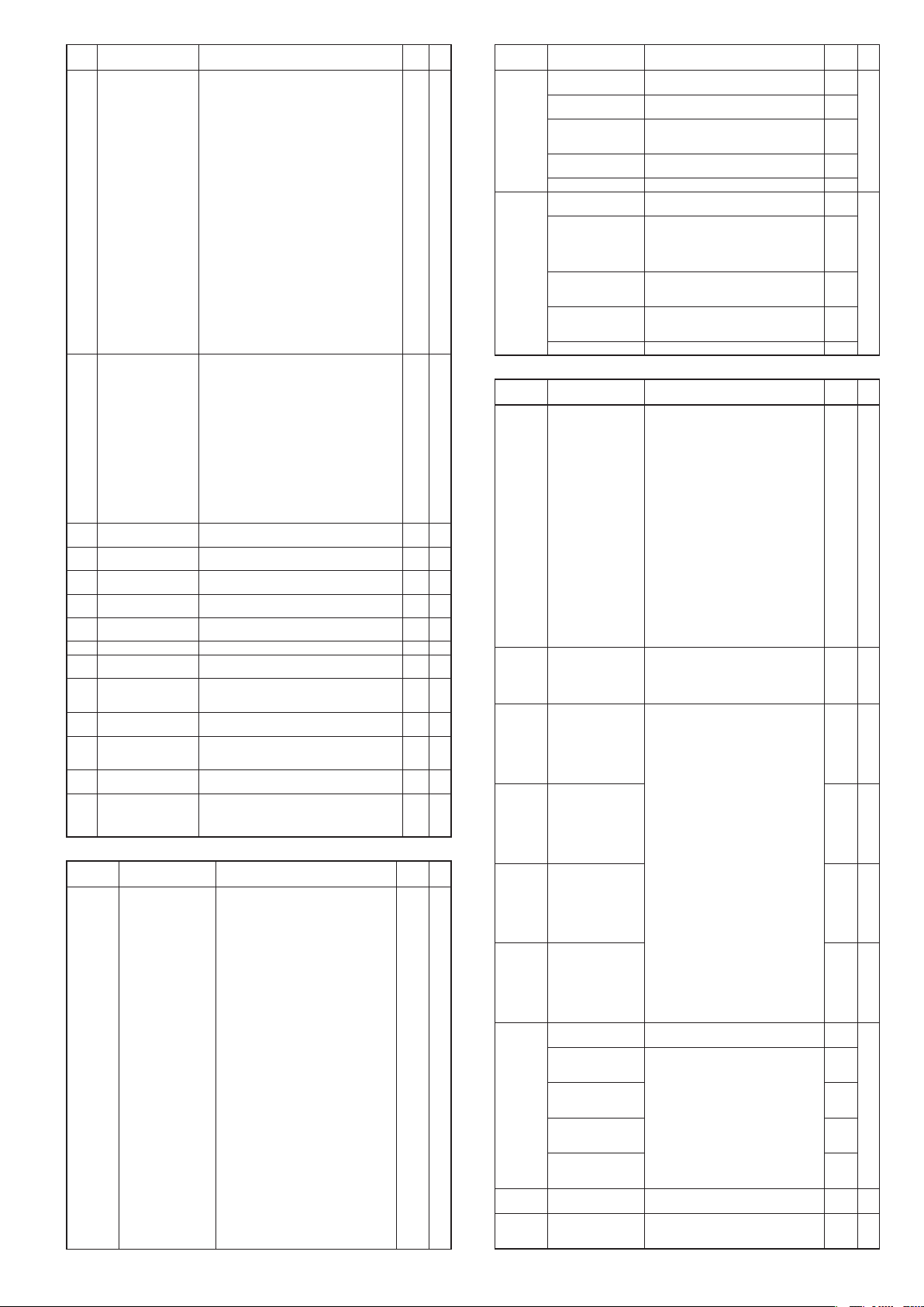
Display Item Contents Initial
MS indicating lamp
C 8 1
ON condition
(1st priority)
MS indicating lamp ON
C 82
status (1st priority)
MS indicating lamp ON
C 83
condition (2nd priority)
MS indicating lamp ON
C 84
status (2nd priority)
MS indicating lamp ON
C 85
condition (3rd priority)
MS indicating lamp ON
C 86
status (3rd priority)
MS indicating lamp
C 87
deviation range
Special function 0 to 15 (0 at power supply ON.) 0 2
C 88
Zener barrier adjustment Rewriting by adjustment is enabled.
C 89
Number of CT1 turns 0: 800 turns
C 90
Number of CT1 power
C 9 1
wire loops
Number of CT2 turns 0: 800 turns
C 92
Number of CT2 power
C 93
wire loops
PV input failure
C 97
(under range) type
0: Nor
mally open (Normally OFF=0)
1: Normally close (Normally ON=1)
2 to 6: Internal event 1 to 5
7 to 9: Internal event 6 to 8 (Invalid in this unit)
10 to 13: Undefined
14: MV1 (ON/OFF, time proportional 1, heat-side,
OPEN-side output)
15: MV2 (time proportional 2, cool-side, CLOSE-side
output)
16, 17: Undefined
18 to 21: DI1 to DI4
22 to 25: Undefined
26 to 30: Internal contact 1 to 5
31 to 33: Undefined
34 to 37: Communication DI1 to DI4
38: MANUAL
39: READY
40: RSP
41: AT
42: During ramp
43: Undefined
44: Alarm
45: PV alarm
46: Undefined
47: Mode key function selection status
48: Event output 1 status
49: Control output 1 status
0: Lit
1: Slow flashing
2: 2 times flashing
3: Fast flashing
4: Left → Right
5: Right → Left
6: Right to left going and returning
7: Deviation OK
8: Deviation graph
9: MV graph
10: Heat-side MV graph
11: Cool-side MV graph
12: MFB graph
13: DI monitor
14: Internal contact monitor
15: Internal event monitor
Same as MS indicating lamp ON condition (1st
priority)
Same as MS indicating lamp ON status (1st priority) 6 2
Same as MS indicating lamp ON condition (1st
priority)
Same as MS indicating lamp ON status (1st priority) 9 2
0 to 9999U 5 2
Numerical value inputting manually is disabled
1 to 40: Setting value multiplied by one hundred
becomes number of winding.
0: 1 time
1 to 6: Number of times
1 to 40: Setting value multiplied by one hundred
becomes number of winding.
0: 1 time
1 to 6: Number of times
0: –10%FS
1:
–5mV(This setting is applicable if C0 1 (PV input
range type) is set for sensor type B (No. 17) or
PR40-20 (No. 23))
value
39 2
1 2
44 2
1 2
0.00 2
8 2
1 2
8 2
1 2
0 0
Event assignment bank: EvCF
Display Item Contents Initial
E 1.C 1 to
E5.C 1
Operation type of
internal event 1 to 5
Configuration 1
Operation type
0: No event
1: PV high limit
2: PV low limit
3: PV high/low limit
4: Deviation high limit
5: Deviation low limit
6: Deviation high/low limit
7: Deviation high limit (Final SP reference)
8: Deviation low limit (Final SP reference)
9: Deviation high/low limit (Final SP reference)
10: SP high limit
11: SP low limit
12: SP high/low limit
13: MV high limit
14: MV low limit
15: MV high/low limit
16: CT1 heater burnout/over-current
17: CT1 heater short-circuit
18: CT2 heater burnout/over-current
19: CT2 heater short-circuit
20: Loop diagnosis 1
21: Loop diagnosis 2
22: Loop diagnosis 3
23: Alarm (status)
24: READY (status)
25: MANUAL (status)
26: Invalid
27: During AT execution (status)
28: During SP ramp (status)
29: Control direct action (status)
30: Invalid
31: Invalid
32: Timer (status)
33: MFB high/low limit
value
0 0
User
level
User
level
Display Item Contents Initial
E 1.C2 to
E5.C2
E 1.C3 to
E5.C3
Internal event 1 to 5
Configuration 2
1st digit: Direct/Reverse 0: Direct
2nd digit: Stand-by 0: None
3rd digit: EVENT state
at READY
4th digit: Undefined 0 0
Internal event 1 to 5
Configuration 3
1st digit: Alarm OR 0: No event
2nd digit: Special OFF 0: As normal execution
3rd digit: Delay time unit 0: 0.1s
4th digit: Undefined 0 0
Digits are called as 1st digit, 2nd digit, 3rd digit
and 4th digit from the right end digit.
1: Reverse
1: Standby
2: Standby + Standby at SP change
0: Continue
1: Forced OFF
Digits are called as 1st digit, 2nd digit, 3rd digit
and 4th digit from the right end digit.
1: Alarm direct + OR operation
2: Alarm direct + AND operation
3: Alarm reverse + OR operation
4: Alarm reverse + AND operation
1: Event OFF at the event setting value
(main)=0
1: 1s
2: 1min
DI assignment bank: dI
Display Item Contents Initial
dI 1. 1 to
dI 5. 1
dI 1.2 to
dI 5.2
dI 1.3 to
dI 5.3
dI 1.4 to
dI 5.4
dI 1.5 to
dI 5.5
dI 1.6 to
dI 5.6
dI 1.7 to
dI 5.7
dI 1.8 to
dI 5.8
dI 1.9 to
dI 5.9
Internal contact 1 to 5
Operation type
Internal contact 1 to 5
Input bit operation
Internal contact 1 to 5
Input assignment A
Internal contact 1 to 5
Input assignment B
Internal contact 1 to 5
Input assignment C
Internal contact 1 to 5
Input assignment D
Internal contact 1 to 5
Polarity A to D
1st digit: Polarity A
(Polarity of input
assig
nment A)
2nd digit: Polarity B
(Polarity of input
assig
nment B)
3rd digit: Polarity C
(Polarity of input
assig
nment C)
4th digit: Polarity D
(Polarity of input
assig
nment D)
Internal contact 1 to 5
Polarity
Internal contact 1 to 5
Internal event
No
.assignment
0: No function
1: LSP group selection (0/+1)
2: LSP group selection (0/+2)
3: LSP group selection (0/+4)
4: PID group selection (0/+1)
5: PID group selection (0/+2)
6: PID group selection (0/+4)
7: RUN/READY selection
8: AUTO/MANUAL selection
9: Invalid
10: AT Stop/Start
11: Invalid
12: Control action direct/reverse selection (As
per setting/opposite operation of setting)
13: SP ramp Enabled/Disabled
14: PV Hold (No-hold/Hold)
15: PV maximum value hold (No-hold/Hold)
16: PV minimum value hold (No-hold/Hold)
17: Timer Stop/Start
Release of all DO latches (Continue/Release)
18:
19: Invalid
20: Invalid
0: Disabled. (Input of default)
1: Function 1 ((A and B) or (C and D))
2: Function 2 ((A or B) and (C or D))
3: Function 3 (A or B or C or D)
4: Function 4 (A and B and C and D)
0: Normally open (OFF, 0)
1: Normally close (ON, 1)
2: DI1
3: DI2
4: DI3
5: DI4
6 to 9: Undefined
10: Internal event 1
11: Internal event 2
12: Internal event 3
13: Internal event 4
14: Internal event 5
15 to 17: Undefined
18: Communication DI1
19: Communication DI2
20: Communication DI3
21: Communication DI4
22: MANUAL mode
23: READY mode
24: Undefined
25: During AT execution
26: During SP ramp
27: Undefined
28: Alarm is enabled.
29: PV alarm is enabled.
30: Undefined
31: Mode key function selection status
32: Event output 1 status
33: Control output 1 status
Digits are called as 1st digit, 2nd digit, 3rd digit
and 4th digit from the right end digit.
0: Direct
1: Reverse
0: Direct
1: Reverse
0: Every internal event
1 to 5: Internal event numbers
value
0000 0
0
0
0
0000 2
0
0
0
value
0 0
0 2
2 to 5
or 0
0 2
0 2
0 2
0000 2
0
0
0
0
0 2
0 2
User
level
User
level
2
E7
Page 16

Do assignment bank: dO
Display Item Contents Initial
Ot 1. 1 to
Ot2. 1
Ev 1. 1 to
Ev3. 1
Ot 1.2 to
Ot2.2
Ev 1.2 to
Ev3.2
1.3 to
Ot
Ot2.3
Ev 1.3 to
Ev3.3
Ot 1.4 to
Ot2.4
Ev 1.4 to
Ev3.4
Ot 1.5 to
Ot2.5
Ev 1.5 to
Ev3.5
Ot 1.6 to
Ot2.6
Ev 1.6 to
Ev3.6
Ot 1.7 to
Ot2.7
Ev 1.7 to
Ev3.7
Ot 1.8 to
Ot2.8
Ev 1.8 to
Ev3.8
Control output 1 to 2,
event output 1 to 3
ation type
Oper
Control output 1 to 2,
event output 1 to 3
O
utput assignment A
Control output 1 to 2,
event output 1 to 3
O
utput assignment B
Control output 1 to 2,
event output 1 to 3
utput assignment C
O
Control output 1 to 2,
event output 1 to 3
utput assignment D
O
Control output 1 to 2,
event output 1 to 3
olarity A to D
P
1st digit: Polarity A 0: Direct
2nd digit: Polarity B 0
3rd digit: Polarity C 0
4th digit: Polarity D 0
Control output 1 to 2,
event output 1 to 3
olarity
P
Control output 1 to 2,
event output 1 to 3 Latch
0: Input of default
1: MV1 (ON/OFF control output, time
proportional output, heat-side proportional
output of heat/cool control)
2: MV2 (cool-side proportional output of heat/
cool control)
3: Function 1 ((A and B) or (C and D))
4: Function 2 ((A or B) and (C or D))
5: Function 3 (A or B or C or D)
6: Function 4 (A and B and C and D)
0: Normally open (OFF, 0)
1: Normally close (ON, 1)
2: Internal event 1
3: Internal event 2
4: Internal event 3
5: Internal event 4
6: Internal event 5
7 to 13: Undefined
14: MV1
15: MV2
16, 17: Undefined
18: DI1
19: DI2
20: DI3
21: DI4
22 to 25: Undefined
26: Internal contact 1
27: Internal contact 2
28: Internal contact 3
29: Internal contact 4
30: Internal contact 5
31 to 33: Undefined
34: Communication DI1
35: Communication DI2
36: Communication DI3
37: Communication DI4
38: MANUAL mode
39: READY mode
40: Undefined
41: During AT execution
42: During SP ramp
43: Undefined
44: Alarm is enabled.
45: PV alarm is enabled.
46: Undefined
47: Mode key function selection status
48: Event output 1 status
49: Control output 1 status
Digits are called as 1st digit, 2nd digit, 3rd digit
and 4th digit from the right end digit.
1: Reverse
0: Direct
1: Reverse
0: Disabled
1: Enabled (La
2: Enabled (Latch at OFF, except at the time of
tch at ON)
initialization after power ON)
User function bank: UF
Display Item Contents Initial
UF- 1
UF-2
UF-3
UF-4
UF-5
UF-6
UF-7
UF-8
User function
definition1
User function
definition2
User function
definition3
User function
definition4
User function
definition5
User function
definition6
User function
definition7
User function
definition8
This is the display in upper display. The setup
exception is as follows:
----: Yet to be registered.
P-_ : Proportional band of the PID group in
use
I -_ : Integration time of the PID group in
use
d-_ : Derivative time of the PID group in
use
rE-_ : Manual reset of the PID group in use
OL-_ : MV low limit of the PID group in use
OH-_ : MV high limit of the PID group in use
P-_ C: Cool-side proportional band of the
PID group in use
I -_ C: Cool-side integration time of the PID
group in use
d-_ C: Cool-side derivative time of the PID
group in use
Ol._ C: Cool-side MV low limit of the PID
group in use
Oh._ C: Cool-side of MV high limit of the PID
group in use
value
0 2
14, 15
or
2 to 4
0 2
0 2
0 2
0000 2
0
0 2
0 2
value
- - - - 1
- - - - 1
- - - - 1
- - - - 1
- - - - 1
- - - - 1
- - - - 1
- - - - 1
User
level
User
level
Lock bank: LOC
Display Item Contents Initial
LOC
C.LOC
2
L.LOC
PASS
PS 1A
PS2A
PS 1b
PS2b
Key lock 0: All settings are enabled.
Communication lock 0: RS-485 communication read/write is
Loader lock 0: Loader communication read/write is
Password display 0 to 15
Password 1A 0000 to FFFF (hexadecimal value) 0000 0
Password 2A 0000 to FFFF (hexadecimal value) 0000 0
Password 1B 0000 to FFFF (hexadecimal value) 0000 0
Password 2B 0000 to FFFF (hexadecimal value) 0000 0
1: Mode, event, operation display, SP, UF, lock,
manual MV, and mode key can be set.
2: Operation display, SP, UF, lock, manual MV,
and mode key can be set.
3: UF, lock, manual MV, and mode key can
be set.
enabled.
1: RS-485 communication read/write is
disabled.
enabled.
1: Loader communication read/write is
disabled.
5: Password 1A to 2B display
value
0 0
0 2
0 2
0 0
User
level
Instrument information bank: I d
Display I tem Contents Initial
I d0 1
I d02
I d03
I d04
I d05
I d06
I d07
I d08
ROM ID 1 fixed — 2
ROM version 1 XX. XX (2 digits after decimal point) — 2
ROM version 2 XX. XX (2 digits after decimal point) — 2
SLP support Information — 2
EST support version — 2
Manufacturing date code
(year)
Manufacturing date code
(month, day)
Serial No. — 2
Year −2000
Ex.: “3” means the year 2003.
Month + Day ÷ 100
Ex.: “12.01” means the 1st day of December
Specications are subject to change without notice.
value
— 2
— 2
User
level
(10)
1-12-2 Kawana, Fujisawa
Kanagawa 251-8522 Japan
: https://www.azbil.com
URL
E8
1st edition: Sep. 2003
23rd edition: Oct. 2018 (V)
 Loading...