

Page 1
Operator Panel
for Infilex™ AC / Infilex™ GC / Infilex™ GD
Model QY5100W0000 (Panel Mount Type)
Model RY5001Q0000 (Integral Type)
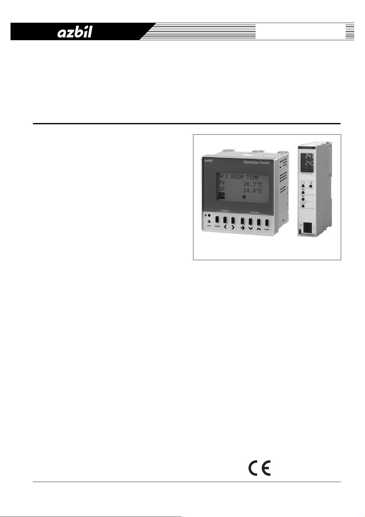
General
Operator Panel is a user terminal for data display and
configuration, which can be connected to a remote unit:
Infilex AC, Infilex GC, or Infilex GD. Two types of Operator
Panel are available. Panel mount type (Model
QY5100W0000) is mounted on the door of the control
panel cabinet. Integral type (Model QY5100W0000) is
attached directly to the remote unit or to its I/O module to
integrate with the remote unit.
The Operator Panel can display all the points that the
remote unit has. Points to be modified (by changing their
data configuration) or operated, such as parameters, AO
(analog output), and DO (digital output), can be modified or
operated through the Operator Panel.
By connecting the Operator Panel to a remote unit (Infilex
AC, Infilex GC, or Infilex GD), the remote unit can be
managed not only through client PC of our BMS (building
management system), savic-net
Operator Panel at the installation site. This greatly
improves the efficiency of the building management.
Additionally, the Operator Panel facilitates status indication
of the points, and allows a remote unit to be easily used as
standalone.
Features
• Display of points:
All points of the remote unit can be managed through
the Operator Panel.
The Operator Panel displays the points as follows:
- Group-points mode
Points divided into up to 4 groups are displayed
per group.
- All-points mode
All the points of the remote unit are displayed.
The points that can be modified or operated through the
Operator Panel can be modified or operated in either
mode. Additionally, one point selected among the
ON/OFF points and the alarm points of the remote unit
can be continuously displayed.
• Operation restriction:
ON/OFF operation and data configuration change
through the Operator Panel can be restricted.
™
FX, but also through the
Specifications/Instructions
• Functions for a standalone remote unit:
When the remote unit connected to the Operator Panel
is standalone, an operation schedule of the point
specified to continuously display its status can be set
through the Operator Panel. Additionally, the Operator
Panel has a manual override function for AO and DO.
• LCD backlight and LED:
Model QY5100W000 is equipped with an LCD
backlight, and Model RY5001Q0000 is equipped with
a 7 segment LED. Operator Panel thus displays the
data and allows the operators to operate even in a
dark place.
• CE Marking certified product:
Operator Panel (both panel mount type and integral
type) conforms to all the applicable standards of CE
Marking (Class A).
Model QY5100W0000
(Panel mount type)
Model RY5001Q0000
(Integral type)
AB-6546
1
Page 2
AB-6546
Safety Instructions
Please read instructions carefully and use the product as specified in this manual. Be sure to keep this manual near by for
ready reference.
Usage Restrictions
This product is targeted for general air conditioning. Do not use this product in a situation where human life may be affected. If
this product is used in a clean room or a place where reliability or control accuracy is particularly required, please contact Azbil
Corporation’s sales representative. Azbil Corporation will not bear any responsibility for the results produced by the operators.
WARNING
• DANGER: To prevent the risk of severe or fatal electrical shock, always disconnect power source and product
power supply before performing any wiring.
• Be sure to ground with 100 Ω or lower ground resistance. Improper grounding may cause electrical shock or
equipment damages.
• Do not detach the terminal cover at any time except when wiring. After wiring, be sure to attach the terminal cover.
Before attaching/detaching the terminal cover, make sure that the wires are not current-carrying to prevent
electrical shock.
• Disconnect power before the product replacement to prevent electrical shock.
• Do not disassemble the product. Disassembly may result in electrical shock.
CAUTION
• Installation and wiring must be performed by qualified personnel in accordance with all applicable safety
Trademark information:
Infilex, savic-net, and Neopanel are trademarks of Azbil Corporation in Japan or in other countries.
standards.
• All wiring must comply with local codes of indoor wiring and electric installation rules.
• Use crimp terminal lugs with insulation for electric wires connected to the product screw terminals.
• Connect cables to the power source with terminals or the like for permanent connection.
• Make sure all the wires are tightly connected to prevent heat generation or equipment damages.
• Install a circuit breaker or circuit protector in the power supply circuit that supplies the power to the product.
• Lightning protection based on regional characteristics and building structure is needed in order to minimize
lightning damages.
• If more than the rated power supply voltage is applied, product replacement is required for safety.
• Noise protection is necessary when the product is installed in a location close to many noise sources.
• Do not block the vent holes on the upper or lower part of the product to prevent equipment damages. Remove
protective sheet after installation and wiring.
• This product must be operated under the operating conditions (power, temperature, humidity, vibration, shock,
installation position, atmospheric condition, etc) specified in this manual to prevent equipment damages.
• Install this product in a location out of reach of unauthorized people.
(e.g. Panel mount type: door of the control panel cabinet / Integral type: inside of the control panel cabinet)
• Do not incinerate this product for waste disposal . Do not reuse all or part of this product, either.
2
Page 3
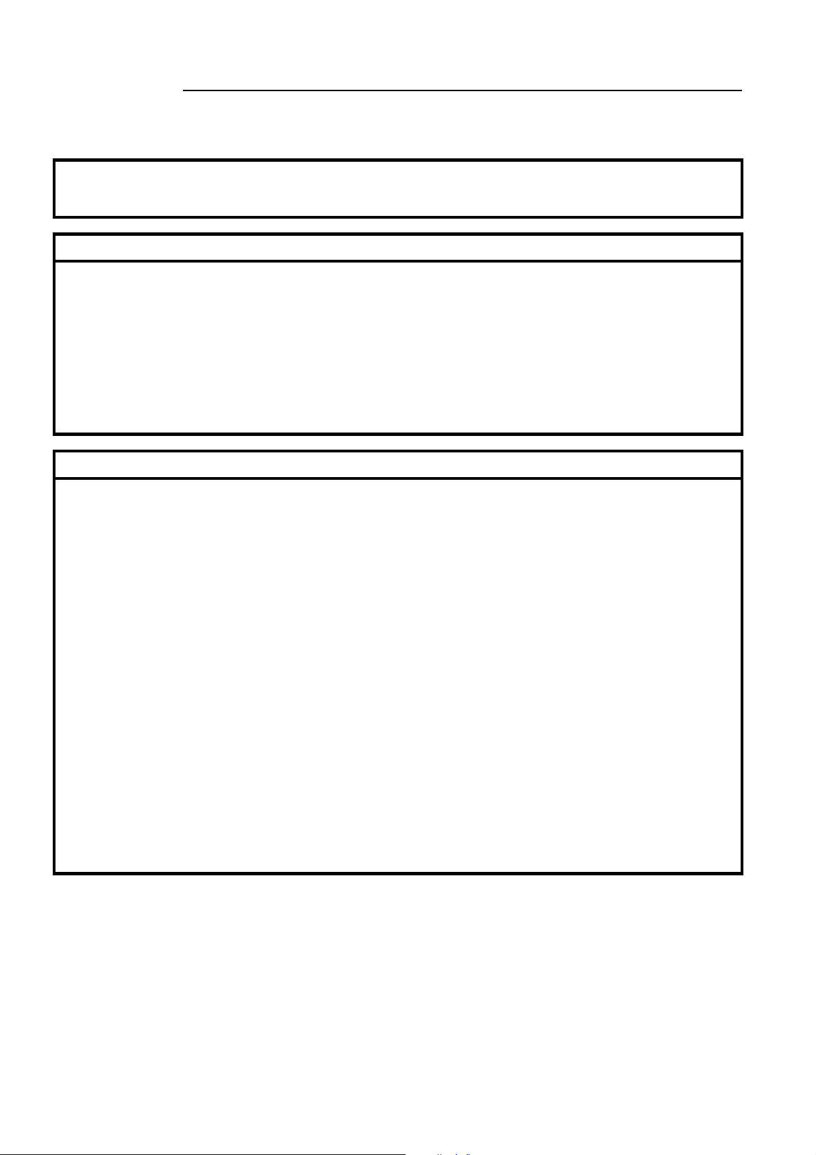
Connection
Infilex AC/
Infilex GC/
Infilex GD
Functions
Functions common
to:
- Operator Panel
connected with the
system
- Operator Panel
connected with the
standalone remote
unit.
and
AB-6546
UT (user
terminal)
module
DP-bus
(Display panel)
Model QY5100W0000
Operator
Panel
(Panel mount type)
Figure 1. Connection examples
Infilex AC/
Infilex GC/
Infilex GD
Model RY5001Q0000
(Integral type)
Operator
Panel
(1/2)
Function Description
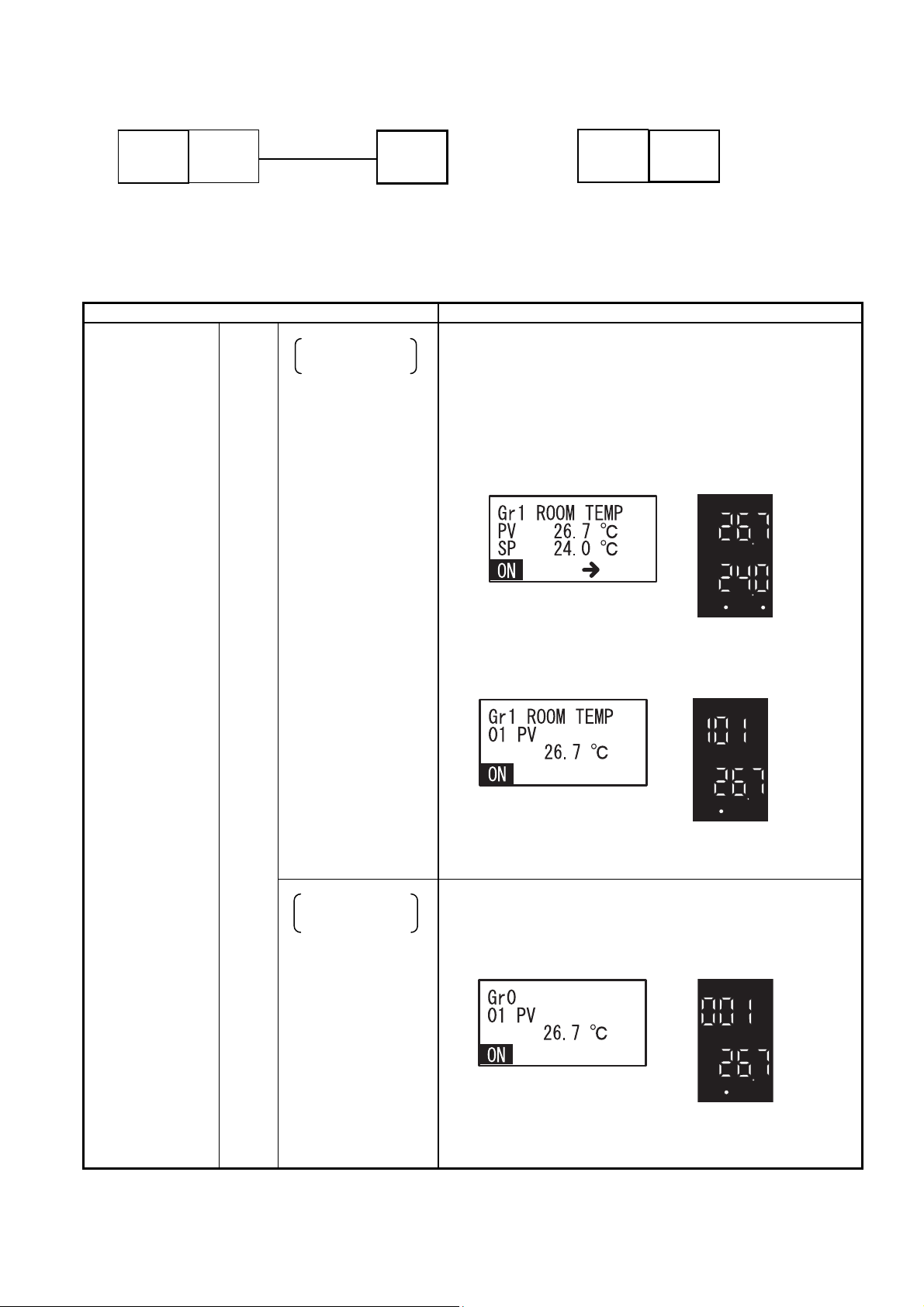
Group-points mode
Display and
data configuration
Points classified by group are displayed. Up to 4 groups can be
configured, and up to 16 points per group can be registered in any
order. Two points (points 1 and 2) are displayed on the group top
display, and the points are respectively displayed on the group scroll
display.
Points to be modified (by changing their data configuration) or
operated, such as parameters, AO, and DO, can be modified or
ON
ALM
OFF
Model RY5001Q0000
(Integral type)
ON
ALM
OFF
Model RY5001Q0000
(Integral type)
ψ
ψ
Display and data configuration of the points
All-points mode
data configuration
Display and
operated in the group-points mode.
Model QY5100W0000
(Panel mount type)
Model QY5100W0000
(Panel mount type)
Group top display
Group scroll display
All points of the remote unit (max. 99 points) are displayed. The
points are respectively displayed.
Points to be modified (by changing their data configuration) or
operated, such as parameters, AO, and DO, can be modified or
operated in the all-points mode.
Model QY5100W0000
(Panel mount type)
ON
OFF
Model RY5001Q0000
(Integral type)
ψ
ALM
3
Page 4
AB-6546
(2/2)
Function Description
Functions common
to:
- Operator Panel
connected with the
system
and
- Operator Panel
connected with the
standalone remote
unit.
Group-points mode
All-points mode
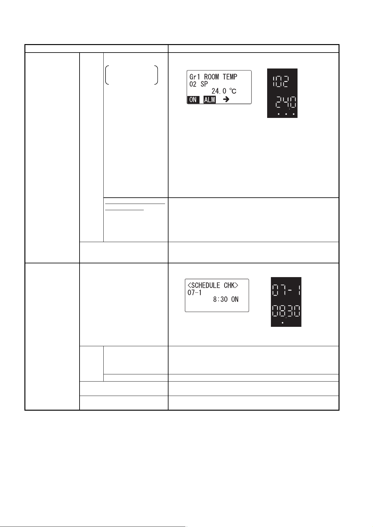
Display of:
- operating status
- alarm status
One point among the ON/OFF and alarm points is specified to
continuously display its status on the bottom line of the screen.
Model QY5100W0000
(Panel mount type)
ψ
ON
ALM
OFF
Model RY5001Q0000
(Integral type)
The above illustration shows that a point with ON/OFF and alarm
status is specified and continuously displayed, indicating the
Display and data configuration of the points
operating status ‘ON’ and the alarm status ‘reported.’
When the operating status is ‘OFF’ and the alarm status is ‘not
reported,’
- Model QY5100W0000: [ON] or [ALM] is not displayed.
- Model RY5001Q0000: Green dot above [OFF] is on and
the green dot above [ALM] is off.
Available only for Model
QY5100W0000
Display of:
- Group name
- Point abbreviated
name
- Engineering unit
Operation restriction
Group names, abbreviated point names, and engineering unit are
displayed.
Note that an abbreviated point name is displayed using up to 4
alphanumeric characters, and a group name is displayed using up
to 12 alphanumeric characters.
Operation and data configuration functions can be restricted to
prevent careless configuration change or undesirable ON/OFF
operation.
Functions of
Operator Panel
connected with the
standalone remote
unit
Schedule display*
Operation schedules for current day and the following day are
displayed.
Operation schedule
The operation schedule can be set through the Operator Panel
Model QY5100W0000
(Panel mount type)
ψ
ON
ALM
OFF
Model RY5001Q0000
(Integral type)
when it is connected to the standalone remote unit. Up to 8
setting*
Schedule
Holiday schedule
Current date and time setting
schedules per day can be set and displayed for 8 days of the week
(Monday through Sunday and one holiday).
Dates for the holiday operation schedule can be set and displayed.
Current date and time (year, month, day, hour, and minute) can be
set.
Manual override
For inspection and maintenance, manual operation and setting can
be set to override the output signals from the remote unit.
∗Note:
Schedule display and setting functions are applicable only to the ON/OFF point specified to continuously display its status. If an alarm
point is specified, the schedule display and setting function is not applicable.
4
Page 5

Points to be continuously displayed on the screen (point types with their operating/alarm status)
Point type Operating status Alarm status
SAP
(Status Alarm Point)
CAP
(Command with Status Alarm Point)
SOP*
1
(Status Only Point)
COP
(Command Only Point)
CCP
(Command with COS (Change of Status) Point)
AOP
(Alarm Only Point)
Notes:
∗1 Status Only Point, which does not have any command, can be specified to continuously display on the screen.
∗2 If CCP or CAP disagrees with its COS, its indicator [ON] or [OFF] flashes.
9 9
2
9*
9
9
9
2
9*
9
AB-6546
5
Page 6

AB-6546
Specifications: Model QY5100W0000 (Panel Mount Type)
Main unit specifications
Item Specification
Power supply Model QY5100W0000
Environmental
conditions
Status indication LED (Green) Power ON: Power ON, OFF: Power OFF
Communication DP-bus
Display
Weight 400 g
Material / color Modified PPE / light gray
connection
Rated operating
conditions
Transport and storage
conditions
LCD
Key
Power M3 screw Terminal
Communication (DP-bus) M3 screw (Modular connection*)
Rated voltage 100 V AC to 240 V AC, 50 Hz/60 Hz
Allowable voltage range 85 V AC to 264 V AC
Power consumption 8 VA
Ambient temperature 0 °C to 50 °C
Ambient humidity 10 %RH to 85 % RH (Non-condensing)
Altitude 2000 m or lower
Vibration 5.9 m/s
Ambient temperature -20 °C to 60 °C
Ambient humidity 5 %RH to 85 % RH (Non-condensing)
Vibration (for storage) 5.9 m/s2 or less (at 10 Hz to 150 Hz)
Vibration (for transport) 9.8 m/s
Transmission system RS-485
Transmission speed 4800 bps
Transmission distance 10 m
Number of remote units to
be connected
Resolution 128 × 64 (dots)
Gradation 2 tones: black and white
Backlight LED backlight
Contrast adjustment Trimmer
Material Silicon rubber Input
Key names [mode], [<], [>], [→], [∧], [∨], [enter]
2
or less (at 10 Hz to 150 Hz)
2
or less (at 10 Hz to 150 Hz)
1
∗ Modular adaptor is pre-connected to the M3 screw terminals.
Wiring specifications
Item Wiring Wiring length Condition
Power supply JIS* IV 2.0 mm2 or JIS CVV 2.0 mm2 or greater ⎯ ⎯
Ground JIS IV 2.0 mm2 or JIS CVV 2.0 mm2 or greater ⎯ Ground resistance: 100 Ω or lower
DP-bus Model DY7210 Connector cable,
Model DY7220 Short connector cable, or
Cable compliant to EIA/TIA-568 Category 5 or above
∗JIS: Japanese Industrial Standards
10 m ⎯
Model Numbers: Model QY5100W0000 (Panel Mount Type)
Base model number Power ⎯ Description
QY5100
W 100 V AC to 240 V AC
Note:
Operation manual for Model QY5100W0000 (AB-6547) is available. When you order the product, request the manual if necessary.
Operator Panel for Infilex AC / Infilex GC / Infilex GD
Panel mount type (Mounted on the door of the control panel cabinet.)
0000 ⎯
6
Page 7

AB-6546
Specifications: Model RY5001Q0000 (Integral Type)
Main unit specifications
Item Specification
Environmental
conditions
Display
Weight 170 g
Material / color Modified PPE / light gray
Rated operating
conditions
Transport and
storage
conditions
LED
Key
Ambient temperature 0 °C to 50 °C
Ambient humidity 10 %RH to 90 %RH (Non-condensing)
Altitude 2000 m or lower
Vibration When assembled with Infilex AC:
5.9 m/s
When assembled with Infilex GC/Infilex GD:
3.2 m/s
Ambient temperature -20 °C to 60 °C
Ambient humidity 5 %RH to 95 %RH (Non-condensing)
Vibration (for storage) When assembled with Infilex AC:
Vibration (for transport) 9.8 m/s
7 segment LED
Dot LED for status indication [OFF], [ON], and [→] in green
Material Silicon rubber Input
Key names [MODE], [∧], [∨], [ENTER], [→]
5.9 m/s
When assembled with Infilex GC/Infilex GD:
3.2 m/s
2
or less at 10 Hz to 150 Hz
4 digit × 2 lines (Upper line in green, lower line in red)
Upper line: Point number is displayed.
Lower line: Max. 6 digit number is displayed. (Upper 2 digits are
displayed first, and lower 4 digits are displayed with [∧] key.) For the
decimal number, max. 3 digits after the decimal point are displayed.
[ALM] in red.
2
or less at 10 Hz to 150 Hz
2
or less at 10 Hz to 150 Hz
2
or less at 10 Hz to 150 Hz
2
or less at 10 Hz to 150 Hz
Wiring specifications
Item Wiring Wiring length Condition
Remote Controller bus Model DY7210 Connector cable,
Model DY7220 Short connector cable, or
EIA/TIA-568 Category 3 or over
50 m ⎯
Model Numbers: Model RY5001Q0000 (Integral Type)
Base model number ⎯ ⎯ Description
RY5001
Q ⎯
Note:
Operation manual for Model RY5001Q0000 (AB-6642) is available. When you order the product, request the manual if necessary.
Operator Panel for Infilex AC / Infilex GC / Infilex GD
Integral type (Assembled with Infilex AC / Infilex GC / Infilex GD)
0000 ⎯
CE Marking Conformity
This product must be installed in a panel cabinet. Besides, the product in the panel cabinet must be out of reach of
unauthorized people who are not well-trained for electric facilities.
This product complies with the following Electromagnetic Compatibility (EMC) and the Low Voltage Directive (LVD).
EMC: EN61326-1 Class A, Table 2 (For use in an industrial electromagnetic environment)
LVD: EN61010-1 Overvoltage category II
Pollution degree 2
7
Page 8

AB-6546
r
r
Dimensions: Model QY5100W0000 (Panel Mount Type)
<Main unit dimensions>
<Mounting panel cutout dimensions>
91.8
91
70
Figure 2. Main unit dimensions (mm): Model QY5100W0000
+0.5
92
30 or wide
Figure 3. Mounting panel cutout dimensions (mm): Model QY5100W0000
0
91.8
96
+0.5
0
92
30 or wide
96
8
Page 9

Dimensions: Model RY5001Q0000 (Integral Type)
<Main unit dimensions>
Figure 4. Main unit dimensions (mm): Model RY5001Q0000
30
AB-6546
90
140
9
Page 10

AB-6546
A
Parts Identification: Model QY5100W0000 (Panel Mount Type)
Displays the operation status
and/or alarm status of the
selected point.
Contrast adjustment trimmer
djusts the contrast of the LCD by
turning the trimmer.
(To darken, turn the trimmer
clockwise. To lighten, turn it
counterclockwise.)
Is lit when the power is ON.
Data display panel
Displays the point data,
schedule, operation
restriction, etc.
Operation status display
Alarm status display
Power LED (green)
1) 2) 3) 4) 5) 6) 7)
(1) [mode] key Changes over the point display modes (group-points modes (groups
1 to 4) and all-points mode).
When the Operator Panel is connected to a standalone remote unit,
changes over the schedule display/setting, and current day/time
setting modes.
(2) [<] key Changes to display the point data to the previous point data.
(3) [>] key Changes to display the point data to the next point data.
(4) [→] key For a configuration changeable point, switches the normal display
(5) [∨] key For numeric data configuration, decreases the selected numeric
(6) [∧] key For numeric data configuration, increases the selected numeric digit.
(7) [enter] key Fixes the configured point data.
Figure 5. Parts identification: Model QY5100W0000
(display only) to the configuration change display.
In the configuration change display, selects a digit of the point data to
change.
digit. (The digit (9 to 0) descends one by one. After 0, the digit
returns to 9.)
For ON/OFF operation, switches ON to OFF.
For positive/negative numeric data configuration, changes + to -.
(The digit (0 to 9) ascends one by one. After 9, the digit returns to 0.)
For ON/OFF operation, switches OFF to ON.
For positive/negative numeric data configuration, changes - to +.
When the [enter] and [mode] keys are concurrently kept pressed for
an extended period of time, a point display mode (or a mode unique to
the Operator Panel connected to a standalone remote unit) is
changed to the operation restriction mode.
Configuration changeable/
unchangeable status indicator
Indicates that the currently
displayed point data is changeable.
Point data displayed without the
indicator is unchangeable.
Operation keys
10
Page 11

Parts Identification: Model RY5001Q0000 (Integral Type)
(5)
g
™
(1)
(2)
(3)
(4)
(1) [MODE] key Changes over the point display modes (group-points modes (groups 1
(2) [∧] key Changes to display the point data to the previous point data.
(3) [∨] key Changes to display the point data to the next point data.
(4) [ENTER] key Fixes the configured point data.
(5) [→] key For a configuration changeable point, switches the normal display
to 4) and all-points mode).
When the Operator Panel is connected to a standalone remote unit,
changes over the schedule display/setting, and current day/time setting
modes.
For numeric data configuration, increases the selected numeric digit.
(The digit (0 to 9) ascends one by one. After 9, the digit returns to 0.)
For ON/OFF operation, switches OFF to ON.
For positive/negative numeric data configuration, changes - to +.
For numeric data configuration, decreases the selected numeric digit.
(The digit (9 to 0) descends one by one. After 0, the digit returns to 9.)
For ON/OFF operation, switches ON to OFF.
For positive/negative numeric data configuration, changes + to -.
When the [ENTER] and [MODE] keys are concurrently kept pressed for
an extended period of time, the normal display mode (or a mode unique
to the Operator Panel connected to a standalone remote unit) is
changed to the operation restriction mode.
(display only) to the configuration change display.
In the configuration change display, selects a digit of the point data to
change.
Data display panel
Displays the point data, schedule, operation restriction, etc.
uration changeable/unchangeable status indicator
Confi
Indicates that the currently displayed point data is changeable.
Point data displayed without the indicator is unchangeable.
Operation status display / Alarm status display
Displays the operation status and/or alarm status of the selected point.
Indicates the start-up time with ON LED and the shut-down time with OFF LED when
schedule is displayed.
Port for Remote Controller bus
Connects to Neopanel
Ask Azbil Corporation’s sales personnel for details regarding Neopanel and
Attachment hole for the point assignment list holder
Holds the point assignment list holder* indicating point names and their engineering
units/status.
∗ Note:
Point assignment list holder (Part No. 83167015-001)
is optional requiring separate order.
For a poing assignment list, photocopy the blank point
assignment list included in AB-6642 operation manual
of Model RY5001Q0000 and fill out the list.
Also, digital data (in spreadsheet format) of point
assignment list is available. Ask Azbil Corporation’s
sales personnel for details.
Figure 6. Parts identification: Model RY5001Q0000
or Neoplate with LAN cable.
AB-6546
11
Page 12

AB-6546
f
r
Installation
IMPORTANT:
Do not install Operator Panel in a high temperature environment including locations exposed to heat radiation
from heating/cooling system equipment or to the direct sunlight. Also, install in a location where the displaying
contents can be seen clearly.
Model QY5100W0000 (panel mount type)
Precautions
• Use a minimum of 2 mm thick steel plate for the
mounting panel. (e.g., door of a control panel
cabinet where the Operator Panel is installed.)
• The allowable mounting angle is ranging from
upright position to 10° tilted upwards or
downwards.
• The angle of visibility is 80° (vertical and
horizontal). Be sure to install Model
QY5100W0000 in a location where its LCD is
visible.
• Do not remove the protective sheet until the
wiring work is completed.
Installation procedure
1) Insert Model QY5100W0000 from the front of the
mounting panel.
2) From the rear of the mounting panel, attach the
mounting brackets to Model QY5100W0000.
3) Keep the mounting brackets pushed until its
claws are engaged with the grooves on Model
QY5100W0000.
4) Tighten the screws of the mounting brackets attached to the top and the bottom of Model QY5100W0000.
Mounting bracket screws
Mounting brackets
Cutout portion o
the mounting panel
Mounting panel
Grooves on the top and
bottom sides fo
mounting brackets
Min. 2 mm thick
Main unit of Model QY5100W0000
Figure 7. Model QY5100W0000 installation
IMPORTANT:
Tighten the screws supplied with the mounting brackets until the mounting brackets get unshaken. Then, rotate (to tighten)
the screws once to fix Model QY5100W0000 on the mounting panel.
If the screws are tightened excessively, the case of Model QY5100W0000 may get deformed.
Model RY5001Q0000 (integral type)
Model RY5001Q0000, as well as the other modules (I/O and UT) connected to the Infilex GC/Infilex GD/Infilex AC basic unit,
is mounted on a DIN rail. The connectable modules including Model RY5001Q0000 vary because the power supplied by the
basic unit is limited. For details about installing Model RY5001Q0000, please refer to the respective
Specifications/Instructions and Installation Manual.
Product Document number Document type
Infilex AC (for NC-bus) AB-6438 Specifications/Instructions
Infilex AC (for LonTalk protocol) AB-6584 Specifications/Instructions
Infilex AC (for IP) AB-6489 Specifications/Instructions
Infilex GC (for NC-bus) AB-6528 Specifications/Instructions
Infilex GC (for LonTalk protocol) AB-6580 Specifications/Instructions
Infilex GC (for IP) AB-6541 Specifications/Instructions
Infilex GD (for NC-bus) AB-6529 Specifications/Instructions
Infilex GD (for LonTalk protocol) AB-6581 Specifications/Instructions
Infilex GD (for IP) AB-6542 Specifications/Instructions
Modules (I/O, UT, Operator Panel) AB-6527 Specifications/Instructions
Infilex Series for LonTalk Protocol AB-6651 Installation Manual
12
Page 13

AB-6546
Wiring: Model QY5100W0000 (Panel Mount Type)
WARNING
• Be sure to ground with 100 Ω or lower ground resistance. Improper grounding may cause electrical shock or
equipment damages.
CAUTION
• Install a circuit breaker or circuit protector in the power supply circuit that supplies the power to the product.
IMPORTANT:
• Use max. φ5.8 mm (outer diameter) crimp terminal lugs.
• Multiple cables cannot be connected together to the power supply terminal. Avoid daisy-chain connection for the power
supply terminals of Model QY5100W0000.
Connecting procedure
1) Connect the UT (user terminal) module and Model QY5100W0000 with the modular cable. Then, connect power supply.
2) After the wiring installation is completed, peel off the protective sheet before supplying the power.
Power supply terminals
arrangement
H
G
E
Operator Panel Model QY5100W0000
(Rear side)
13
∼
14
15
Figure 8. Connection to UT module
Figure 9. Protective sheet
2. Connect.
1. Connect.
UT module
Modular cable
Protective sheet
Wiring: Model RY5001Q0000 (Integral Type)
Model RY5001Q0000 is directly attached to a Infilex GC/Infilex GD/Infilex AC basic unit or to its I/O module, etc. Wires
connection therefore is not necessary unless Neopanel or Neoplate is connected to Model RY5001Q0000.
(Neopanel/Neoplate is connected to Model RY5001Q0000 with LAN cable. A modular jack (port for Remote Controller bus) is
provided on the front lower side of Model RY5001Q0000. (Refer to Fig. 6.)
13
Page 14

AB-6546
Maintenance
Model QY5100W0000 (panel mount type)
Wipe off the LCD with dry soft cloth when needed.
Any periodic part replacement is required. However, if the
brightness or contrast of the LCD deteriorates, replace the
LCD module.
LCD module: Part No. 83167012-001
If any part other than LCD module gets damaged (e.g. fuse
disconnection), the whole unit requires to be replaced.
LCD module replacement
IMPORTANT:
• Only authorized service personnel are allowed to
replace the LCD.
• Do not touch the power supply part during LCD
replacement.
• Before replacing the LCD, be sure to turn off the
power completely. Always replace the LCD with
the power disconnected.
• Plastic screws are used to prevent static
electricity. Be sure not to excessively tighten them
so as not to break the screws, or be sure not to
lose them. Metal screws cannot be substituted for
the plastic screws.
• Be sure to discharge static electricity charged in
your body (by touching the unpainted metal part of
the panel, etc.) before and during the LCD module
installation.
Required tools:
• Slotted screwdriver
• Phillips screwdriver
1) Remove the front panel using a slotted screwdriver.
Figure 10. Front panel removal
Front panel
2) Remove the transparent cover. Insert a slotted
screwdriver in the clearance on the right, and pry the
transparent cover.
Transparent
cover
Figure 11. Transparent cover removal (1/2)
Hold the pried cover with fingers to pull it out.
Figure 12. Transparent cover removal (2/2)
3) Remove the screw at the lower left of the LCD board.
Figure 13. Screw removal
4) Remove the upper portion of the LCD module. At this
time, note that the LCD module is connected to the LCD
board with the connector.
Figure 14. LCD module removal
Connector
LCD module
14
Page 15

AB-6546
5) Disconnect the connector to remove the LCD module.
Connector
Figure 15. Connector disconnection
6) Mount a new LCD module.
Connect the connector and hook the LCD module with
the claws of the LCD board.
Insert the screw into the hole located at the lower left of
the LCD board, and then engage the LCD module with
the boss at the lower right of the LCD board.
Claw
Boss
Figure 16. LCD module mounting
Screw
7) When the LCD module fits to the LCD board, tighten the
screw at the lower left of the LCD board (in one location).
Model RY5001Q0000 (integral type)
Any part replacement is not available for Model
RY5001Q0000. If any part of Model RY5001Q0000 gets
damaged, the whole unit requires to be replaced.
For details regarding the maintenance, ask Azbil
Corporation’s sales personnel.
IMPORTANT:
Screw-tightening torque is 0.07 N⋅m (0.7 kgf⋅cm).
Larger torque than 0.07 N⋅m may break the screw.
8) Attach the transparent cover to the LCD module. (The
wider side surface (to be inserted into the LCD module)
needs to be located on the right.)
9) Mount the front panel.
15
Page 16

AB-6546
Specifications are subject to change without notice.
Building Systems Company
http://www.azbil.com/
Rev. 5.0 Sep 2015 AB-6546
(J: AI-6546 Rev. 3.4) Printed in Japan.
16
 Loading...