

Azbil MQV9020, MQV9200, MQV0005, MQV0020, MQV9500 User Manual
...
™
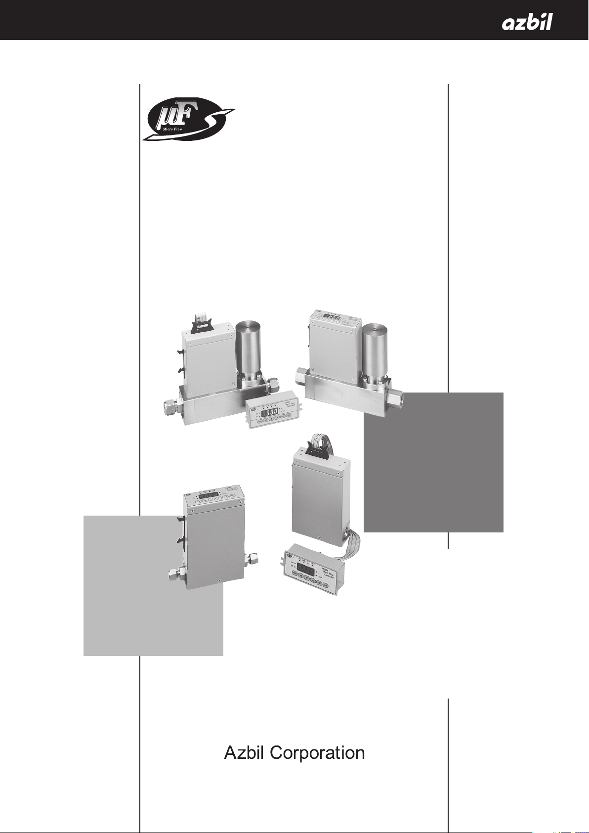
Digital Mass Flow Controller
Standard Gas Model
MQV9005/9020/9200/9500
0002/0005/0020/0050/0200/0500
User’s Manual
No. CP-SP-1204E
Thank you for purchasing an Azbil
Corporation product.
This manual contains information for
ensuring the correct use of this product.
It also provides necessary information
for installation, maintenance, and
troubleshooting.
This manual should be read by those who
design and maintain equipment that uses
this product. Be sure to keep this manual
nearby for handy reference.

IMPORTANT
“Natural gas” in this document refers to city gas in Japan.
NOTICE
Be sure that the user receives this manual before the product is used.
Copying or duplicating this user’s manual in part or in whole is forbidden.
The information and specifications in this manual are subject to change
without notice.
Considerable effort has been made to ensure that this manual is free from
inaccuracies and omissions. If you should find an error or omission, please
contact the azbil Group.
In no event is Azbil Corporation liable to anyone for any indirect, special or
consequential damages as a result of using this product.
© 2006-2018 Azbil Corporation All Rights Reserved.
Micro Flow™, µF™ are trademarks of Azbil Corporation in Japan.
Conventions Used in This Manual
The safety precautions explained in the following section aim to prevent injury to the operator and others, and to
prevent property damage.
Warnings are indicated when mishandling this product
WARNING
CAUTION
In describing the product, this manual uses the icons and conventions listed below.
Use caution when handling the product.
The indicated action is prohibited.
Always follow the indicated instructions.
might result in death or serious injury.
Cautions are indicated when mishandling this product
might result in minor injury to the user, or physical damage
to the product.
Handling Precautions:
Handling Precautions indicate items that the user should pay attention to when handling
the product.
Note:
(1)(2)(3): Numbers within parentheses indicate steps in a sequence or parts of an explanation.
0FF
>>: Indicates the result of an operation, details displayed on the personal computer or other
Notes indicate information that might benefit the user.
This indicates the item or page that the user is requested to refer to.
Indicates a selectable button on a personal computer screen.
devices, or the state of the device after operation.
ii
Safety Precautions
Never allow gases that are within explosive limits to pass through this device. Doing so might
result in an explosion.
If the MQV is to be used for oxygen, make sure that it is a model designed for oxygen use.
Even if a device is designed for oxygen gas, do NOT use it for oxygen gas if it has been used
for some other gas even once. Oil contained in another gas may be deposited on the gascontacting parts and ignite upon reacting with oxygen.
If the device is used for burner air-fuel ratio control, take the necessary countermeasures
with the equipment to prevent the occurrence of backfire and to avoid any influence to the
device even if backfire occurs. Pressure increase or fire in the pipes caused by the backfire of
the burner could damage the controller.
This device cannot be used for measurement or control of hydrogen or helium gas. Use a
model specially designed for hydrogen and helium gases. For information on whether this
device can be used for gases other than the standard compatible gases, be sure to contact
the azbil Group in advance.
Prevent foreign matter from entering the device. If rust, water droplet, oil mist, or dust in the
pipes enters the device, measurement or control error or damage might occur.
If there is a possibility of foreign matter entering the device, provide a filter, strainer or mist
trap capable of eliminating foreign matter 0.1 µm or greater in diameter at the upstream. Be
sure to inspect and replace the filter at regular intervals.
Use this device within the operating differential pressure range. Not doing so may cause
hunting. Continuous hunting could damage the valve.
WARNING
CAUTION
Do not subject this device to pressure above its pressure resistance. Doing so might damage
it.
Be sure to use within the flow-rate range stipulated in the product specifications.
To prevent excessive flow, use a suitable means to control the supply pressure or use a
throttle valve or the like to control the flow rate.
If the flow rate exceeds the upper limit, both the flow rate display and the output voltage/
current may indicate considerably lower values than the actual flow rate.
If damage could result from the abnormal functioning of this device, include appropriate
redundancy in the system design.
iiii
CAUTION
The valve on this device cannot completely shut a flow off. If complete shutoff is required,
provide a shutoff valve separately. When the external valve is closed, it is necessary also to
fully close the valve of the device using either of the following methods:
•
Set the flow rate setpoint to zero.
•
Make the valve operation mode to fully closed.
If this valve remains in normal control status when the external shutoff valve is closed (zero
flow rate), there will be an excessively large flow as soon as the external shutoff valve is
opened. For the MQV0050(J, K), MQV0200(J, K), and MQV0500(J, K), if the external shutoff
valve is closed continuously for 5 minutes or more in control mode or with the valve forced
fully open, the valve overheating limit (AL71) will be activated and the current to the valve
will be forcibly limited.
Before connecting pipes with Swagelok or VCR connections, check the precautions in the
instruction provided by the connecting joint manufacturer.
When separately purchasing a connecting joint, use the following made by Swagelok Co.,
Ltd:
1/4” Swagelok: SS-400-1-6ST (standard)
SS-400-1-6STSC11 (oil-inhibited)
1/2” Swagelok: SS-810-1-8ST (standard)
SS-810-1-8STSC11 (oil-inhibited)
1/4” VCR: SS-4-VCR-1-00032SC11
1/2” VCR: SS-8-VCR-1-8STSC11 or equivalent
Observe the following when using the device (oil-free model) for oxygen gas:
•
Piping should be carried out by a specialist skilled in handling oxygen gas.
•
Use oil-free pipes and parts.
•
Be sure to remove foreign matter, burrs, etc. from the pipes before connecting the device.
The device is a precision instrument. Do not drop it or subject it to impact, or it might be
damaged.
When installing joints (UNF connections), secure the lower part of the main unit in a vise or
the like gripped between rags to protect the finished surfaces, and turn the joint to tighten.
Mount securely in order to prevent vibration. Otherwise, equipment failure could result.
Mount the device horizontally. Do not mount it with the display facing down. Doing so might
cause measurement error or equipment failure.
For the MQV0050(J, K)/0200(J, K)/0500(J, K). use the largest pipe possible in order to reduce
pressure loss in the pipes, and do not install any equipment near the MQV that can cause a
large pressure loss. If there is a large pressure loss in the pipes or equipment, the pressure
of the gas supply to this device (operation differential pressure) will be affected and will
fluctuate greatly with the flow rate. This could result in unstable control.
When making the pipe connections, hold the hexagonal part of the connector section and
turn the pipe to tighten. After connecting, check that there are no gas leaks.
iiiiii
CAUTION
If using Rc connections, take care not to coat with too much sealant. Foreign matter or burrs
in the pipes may also cause measurement errors.
Do not apply a negative voltage or a voltage exceeding 5 V to the external setup voltage
input terminal. Doing so might cause malfunction or equipment failure.
When using a relay for external contact input and/or external 3-way switching input, always
use a relay designed for micro-current use (with gold contacts). Failure to do so could cause
faulty contact, resulting in malfunction.
If there is a risk of a power surge caused by lightning, use a surge protector to prevent fire or
equipment failure.
Gas type switching by external contact input, flow rate switching, and analog input/output
voltage range switching by external 3-way input switching should be done only after
setting the operation mode to fully closed. Switching while controlling could cause large
fluctuations.
Be sure to check that the wiring is correct before turning the power on. Incorrect wiring could
cause damage or malfunction.
Do not apply excessive force to the cables or connector while the connector cable or the AC
adapter is connected. Doing so may damage the connector or the circuit board.
Do not operate the console keys using a sharp object such as a mechanical pencil or
screwdriver. Doing so might damage the console.
When discarding the device, dispose of it as industrial waste, following local regulations.
iviv
The Role of This Manual
A total of 2 different manuals are available for the MQV. Read them as necessary for your specific requirements. If a
manual you require is not available, contact the azbil Group or its dealer.
Digital Mass Flow Controller Standard Gas Model
MQV9005/9020/9200/9500/0002/0005/0020/0050/0200/0500
Manual No. CP-SP-1204E
This manual.
First-time users of the MQV, and those in charge of maintenance or hardware design for
incorporating a MQV controller in instrumentation should read this manual.
This manual outlines the product, tells how to install, wire, and incorporate the product
into instrumentation, and describes its operation, inspection and maintenance,
troubleshooting, and hardware specifications.
MQV9005/9020/9050/9200/9500/0002/0005/0010/0020/0050/0100/0200/0500
Digital Mass Flow Controller User’s Manual for Communication Functions
Manual No. CP-SP-1197E
Personnel who use this device’s communications functions should read this
manual. The manual gives an overview of communications, describes wiring,
transmission protocols, communications data, and troubleshooting, and gives
communications specifications.
vv

Organization of This User’s Manual
This manual is organized as follows.
Chapter 1. INTRODUCTION
This chapter briefly describes this device and its features, and gives a model
selection guide.
Chapter 2. NAMES AND FUNCTIONS OF PARTS
This chapter describes the names and functions of this device’s parts.
Chapter 3. MOUNTING AND WIRING
This chapter describes installation, mounting, wiring and initial settings of this
device.
Chapter 4. BASIC OPERATION
This chapter gives the basis of how to operate this device.
Chapter 5. ADVANCED OPERATION
This chapter describes how to set functions, parameters, controller information
display, and flow rate range.
Chapter 6. MAINTENANCE AND TROUBLESHOOTING
This chapter describes how to investigate and remedy trouble that may occur
during operation of this device.
Chapter 7. SPECIFICATIONS
This chapter describes the device’s specifications and external dimensions.
vivi

Contents
Conventions Used in This Manual
Safety Precautions
The Role of This Manual
Organization of This User’s Manual
Chapter 1. INTRODUCTION
Introduction ...................................................................................................................................................... 1-1
Features ............................................................................................................................................................... 1-1
Functions ............................................................................................................................................................ 1-2
Model selection guide .................................................................................................................................. 1-7
Basic operation and advanced operation .........................................................................................1-10
Chapter 2. NAMES AND FUNCTIONS OF PARTS
Display ................................................................................................................................................................. 2-1
Main unit (MQV9005/9020/9200/9500/0002/0005/0020/0050) ............................................. 2-2
Main unit (MQV0050(J, K) /0200/0500) ................................................................................................ 2-2
Chapter 3. MOUNTING AND WIRING
Mounting ............................................................................................................................................................ 3-2
Piping.................................................................................................................................................................... 3-6
Wiring ................................................................................................................................................................... 3-7
Chapter 4. BASIC OPERATION
4 - 1 Switching Displays .............................................................................................................................................. 4-1
Basic operation ................................................................................................................................................ 4-1
4 - 2 Setting the Flow Rate ......................................................................................................................................... 4-4
Digital flow rate setup .................................................................................................................................. 4-5
Flow rate setup by external contact input (Advanced use) ........................................................ 4-7
Flow rate setup by external 3-way switching input (Advanced use) .....................................4-8
Analog flow rate setup ................................................................................................................................. 4-9
4 - 3 Selecting the Operating Mode ....................................................................................................................4-10
Operating mode selection ........................................................................................................................4-10
Operating mode display ............................................................................................................................4-10
Chapter 5. ADVANCED OPERATION
Setup mode transition operation ........................................................................................................... 5-1
5 - 1 Functions ................................................................................................................................................................. 5-2
Setup method ................................................................................................................................................... 5-2
Function setup items.....................................................................................................................................5-3
5 - 2 Parameters ............................................................................................................................................................5-11
Setup method .................................................................................................................................................5-11
Parameter setup item list ..........................................................................................................................5-12
viivii

5 - 3 Device Information Display ......................................................................................................................... 5-15
Setup method ................................................................................................................................................ 5-15
Device information display item .......................................................................................................... 5-16
5 - 4 Flow Rate Range Change Function and Settings and Display Resolutions After
Change of Range ............................................................................................................................................... 5-17
Setup resolution in the analog setup................................................................................................. 5-18
Chapter 6. MAINTENANCE AND TROUBLESHOOTING
Alarm code display ......................................................................................................................................... 6-1
Troubleshooting guide ................................................................................................................................6-2
Chapter 7. SPECIFICATIONS
Specifications ...................................................................................................................................................7-1
Gas type and control range ..................................................................................................................... 7-11
Relationship between differential pressure and flow rate ..................................................... 7-12
Optional parts (sold separately) ........................................................................................................... 7-14
External dimensions ................................................................................................................................... 7-15
viii
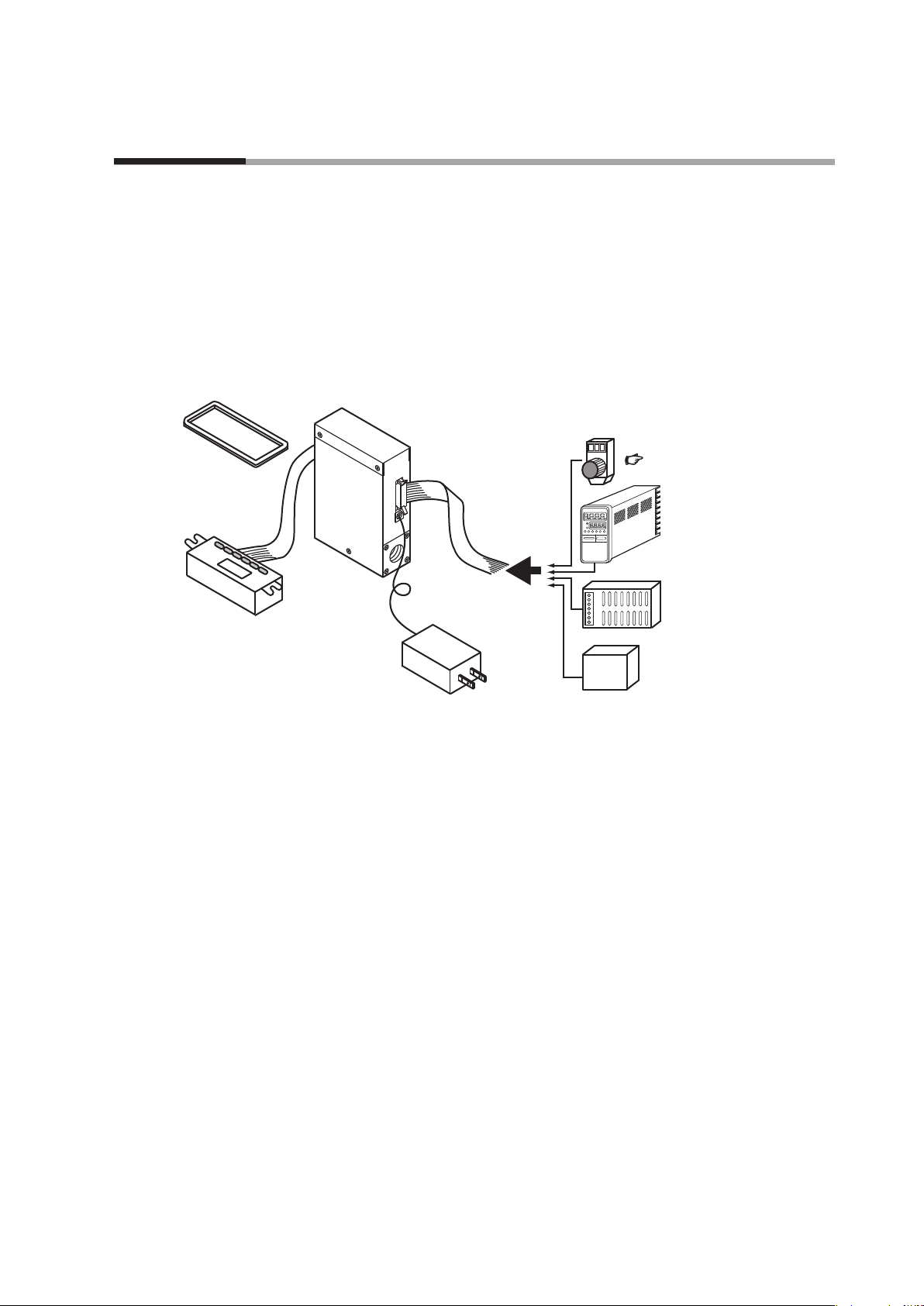
Chapter 1. INTRODUCTION
function)
Potentiometer (sold separately)
Separate display unit
Front cover for
Introduction
MQV high performance, digital mass flow controllers with advanced functions have
been developed for the general industrial application. They feature flow rate control
with high speed and wide rangeability. MQV controllers integrate three component
technologies: the ultra quick response µF (Micro Flow) thermal flow sensor, made
with proprietary Azbil Corporation technology, a proportional solenoid valve, and
advanced actuator control technology. Integrating these technologies has achieved
a high-speed control with low differential pressure.
separate display
(sold separately)
MQV
Features
Cable with dedicated
connector (sold separately)
AC adapter
(sold separately)
for setting ow rate
P.7-14
Controller
(e.g. SDC25/26)
24 V DC power supply
(e.g. WN790A)
RS-485 device
(for models supporting
optional RS-485
communications
Device Configuration
• High-speed controllability
Fast response of 300 ms or less*
(500 ms for the MQV9005/9020, 700 ms for the MQV0050(J, K), MQV0200, and
MQV0500.)
* Response time is the time required for the controlled flow rate to reach ±2 % of the
set value, starting from the fully closed state or from when the set value is changed
during control.
• Low differential pressure operation
MQV controllers can operate at a low differential pressure of 50 kPa or less.
• Wide control range
Wide control range of 1 to 100 % FS (2 to 100 % FS for the MQV9005)
• Wide product line-up
There are two types of models, those with integrated display and those with
separate display. On models with separate display, the display unit can be
detached to allow remote operation via the dedicated 2 m cable.
1-1

Chapter 1. INTRODUCTION
• User-friendly
Runs on a general-purpose 24 V DC power supply, and the MQV's internal
power circuit and input/output circuits are isolated. When multiple MQV are
driven through the analog inputs and outputs, as with a PLC, they can all use
a common power supply even if the PLC's analog modules are not isolated by
channel. Therefore, even without individual power supplies for each device,
problems with one circuit do not affect adjacent ones. Also provided is a handy
AC adapter (sold separately) for easy use in the laboratory.
• Display direction can be changed (models with integrated display only)
The direction of the display can be rotated 180˚ to match the direction of the gas
flow, in case it was mounted the other way.
• Improved design (separate display model)
A front cover (sold separately) hides the mounting screws of the separate display
on the panel surface and improves the appearance.
Functions
• Various additional functions
The functions listed below are all standard.
All MQV models have the functions described below.
For function setup, Chapter 5. ADVANCED OPERATION.
• Multi-setup (function setup C-04)
Quickly switch to one of eight preset flow set value by key operation or external
input. If “Switching of SP No.” is set to external 3-way switching input, up to
three set values can be switched.
• Gas type switching (function setup C-18, C-26)
The gas type to be used can be selected from the standard compatible gases by
key operation. Additionally, two kinds of gas type settings can be changed by
external contact input.
• Gas type setup (function setup C-18)
The user can set gas type conversion factors for gases other than the standard
compatible gases, and for mixed gases.
For information on gas type conversion factors for various gases, contact the
azbil Group.
1-2
• Control flow range setting (function setup C-24, C-25)
The control flow range can be changed to the desired range (10 to 100 % of
the flow range at factory setting) in units of 1 % FS. The setup and display
resolution levels can be improved by reducing the control flow range.
Additionally, two kinds of control flow ranges can be switched through external
contact input.
• Direct setup (function setup C-2 1)
When changing the flow set value by key input, the controlled flow rate can
follow the set value while changes are being made (the flow set value can be
changed quickly). This function is useful when the user frequently changes set
value, for example when adjusting the flow set value during a trial run.

Chapter 1. INTRODUCTION
• SP ramp control (function setup C-27)
This function is used to set the set value change ramp amount (the rate of
change per second) to a constant value for the start of control and for set value
changes. With this function, the set value change ramp amount can be set more
precisely than with the slow start function. Two different types of ramps can be
set, and there are the following 2 control modes:
•
SP ramp control 1
In SP ramp-up: Ramp 1
In SP ramp-down: Ramp 2
•
SP ramp control 2
In external contact OFF: Ramp 1
In external contact ON: Ramp 2
• SP limit (function setup C-35)
The lower and upper limits of the set value range can be set to desired levels.
(This prevents mistaken high/low settings.)
• Slow start (function setup C-1 7)
Sudden changes in the controlled flow rate, when control is started or when the
set value is changed, can be suppressed. The control speed can be changed in
eight stages within a range of about 1 to 6 seconds.
• Flow rate totalization (function setup C-09 to C-12)
MQV9005: in 0.1 mL units
MQV9020: in 1 mL units
MQV9200/9500: in 0.01 L units
MQV0002/0005: in 0.1 L units
MQV0020/0050: in 1 L units
MQV0050(J, K): in 0.001 m
MQV0200/0500: in 0.01 m3 units
Integrated flow count can be up to eight digits long (to 99,999,999) for each
unit. (Display alternates between first and last 4 digits.) The count can be
reset by key operation or external contact input. Use of external contact input
makes it possible to remotely operate the start, temporary stop, and reset of
totalization. When resetting the integrated count by key operation, the count
restarts automatically after it has been reset. On the other hand, when resetting
with the external contact input (by contact ON), the count restarts when the
contact is turned OFF.
3
units
• Event lamp lighting/output (function setup C-07, C-08)
Two of the event types listed below can be selected. Output ON delay time can
also be set (but delay cannot be set for totalizer pulse output).
•
Integrated flow event output (when the integrated flow event setting is
exceeded.)
•
Totalized pulse output (pulse can be output for each totalizing flow display
unit.)
•
OK output (the control flow rate is within the set value ± allowable range.)
1-3

Chapter 1. INTRODUCTION
•
Flow rate upper or lower limit output (output in comparison with optional
upper or lower limit flow rate set value )
•
Output mode (The four modes — control / fully open / control or fully open /
fully closed — can be identified and output.)
• OK lamp ON/output (function setup C-07, C-08)
The OK lamp can be set to light when the control flow rate is within the set
value ± allowable range. This function is very handy for verifying at a glance
whether or not there is a proper response to a new set value after its value is
changed. OK lamp output can also be used as an interlock signal for subsequent
processes by assigning it to event output and including it in a sequence program.
• PV filter (function setup C-23)
This function is used to average the instantaneous flow rate (control flow rate)
detected value. Use of this function makes it possible to suppress effects of slight
pressure fluctuations.
• Control dead band setup (prevention of valve operation) (function setup
C-22)
This function is used to stop the valve from driving as long as the control flow
rate is within the OK range. Additionally, the OK range (width of dead band)
can be set to the desired level.
• Valve amperage display (function setup C-20)
The electric current supplied to the valve can be displayed in units of 0.0 to
100.0 %. Additionally, use of the valve amperage alarm detection function
makes it possible to detect an inlet pressure change or clogging of the piping at
the outlet.
• Gas type external switching (function setup C-10 to C-12, C-18, C-26)
Two preset types of gases (including one with a user-determined gas type
conversion factor) can be switched by external contact input.
• Control flow rate range external switching (function setup C-10 to C-12,
C-24, C-25)
Two preset control flow ranges can be switched by external contact input.
• PV forced zero (function setup C-29)
This function forcibly sets the detected instantaneous flow rate to 0 (zero) after
the delay time elapses when the flow rate setpoint has been set to 0 (zero) or the
valve mode has been changed to fully closed. This function makes it possible
to ignore the deviation of the instantaneous flow rate zero point caused by
inclination of the piping or the like.
1-4
• Flow rate display unit change (function setup C-37)
This function is used to change the flow rate display unit to L/min or mL/min of
the MQV9200/9500/0002/0005. When multiple devices are used side-by-side,
this function can make the flow rate display units uniform.

Chapter 1. INTRODUCTION
• PV display decimal point change (function setup C-38)
This function is used to shift the decimal point position of the instantaneous
flow rate display one digit left or right. When multiple devices are used side-byside, the number of digits after the decimal point of the flow rate display can be
made uniform.
• Valve forcibly open or close (function setup C-02, C-09 to C-12)
This function is used to forcibly open or close the valve fully by key operation,
external contact input, or external 3-way switching input.
• Automatic shut-off (function setup C-13, C-16)
The valve can be shut off automatically under the following conditions:
•
When the totalized flow count reaches the preset value.
•
When one of the alarms, including flow rate alarms, is triggered.
• ALM (alarm) lamp ON/output/valve shut-off (function setup C-15, C-16 C-20)
The alarm output can be set for high and low deviations in the flow set value
and instantaneous flow rate. Additionally, an alarm judgment delay time can
also be set. If a flow rate alarm occurs or if an alarm occurs during self-diagnosis
of this controller, the valve can be forced fully closed or opened.
Handling Precautions
•
The valve on this device cannot completely shut off.
•
If complete shutoff is required, provide a shutoff valve separately.
• Automatic reset of cumulative count at start of control function (function
setup C-14)
Start of control and reset of totalized flow count can be done simultaneously by
a single action (by key or external switching input). Combining this function
with the automatic shut-off function described above is handy for shutting the
valve off in cases where a fixed totalized flow amount is counted repeatedly.
• Analog scaling (function setup C-28)
This function is used to optionally change the flow rate (between 10 % FS and
100 % FS) corresponding to 100 % FS analog input/output (5 V or 20 mA).
• Analog input (flow set value) range selection (function setup C-05, C-09)
In analog setup, the desired input range can be selected from those shown below
either by key operation or by external 3-way switching input. When doing so,
the voltage input and current input are selected automatically, as they are linked
with the settings of function setup C-06 (analog output type selection). For
example, when the voltage output (0 to 5 V or 1 to 5 V) is selected in C-06,
the voltage input is selected automatically. Likewise, when the current output
(0 to 20 mA or 4 to 20 mA output) is selected, the current input is selected
automatically.
1-5

Chapter 1. INTRODUCTION
•
Internal reference 0 to 5 V input*/External reference 0 to 20 mA input
•
External reference 0 to 5 V input/External reference 0 to 20 mA input
•
External reference 1 to 5 V input/External reference 4 to 20 mA input
* The internal reference 0 to 5 V is used when the 5 V output terminal voltage
(pin No. 20) of this controller is used as the reference.
• Analog output type/range selection (function setup C-06, C-09)
Output can be set either to instantaneous flow rate (PV) or flow set value (SP).
Furthermore, a voltage/current output range can be selected from (1) to (4)
shown below by key operation. Additionally, (1)/(2) or (3)/(4) can be changed
through the external 3-way switching input. (Combinations are switched
because of linkage with the analog input range selection.)
Instantaneous flow rate (PV) output Flow set value (SP) output
(1) 0 to 5 V output
(1) 0 to 5 V output
(2) 1 to 5 V output
(3) 0 to 20 mA output
(4) 4 to 20 mA output
(2) 1 to 5 V output
(3) 0 to 20 mA output
(4) 4 to 20 mA output
1-6
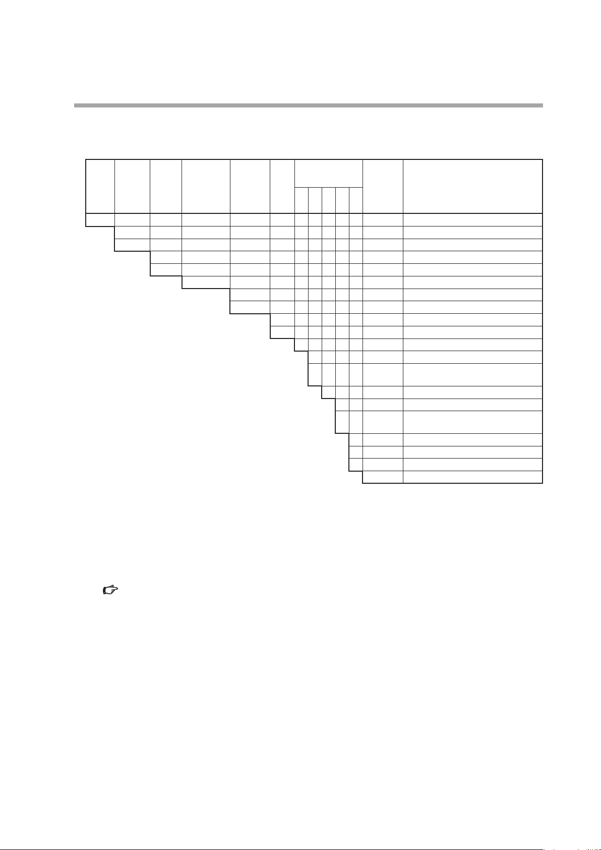
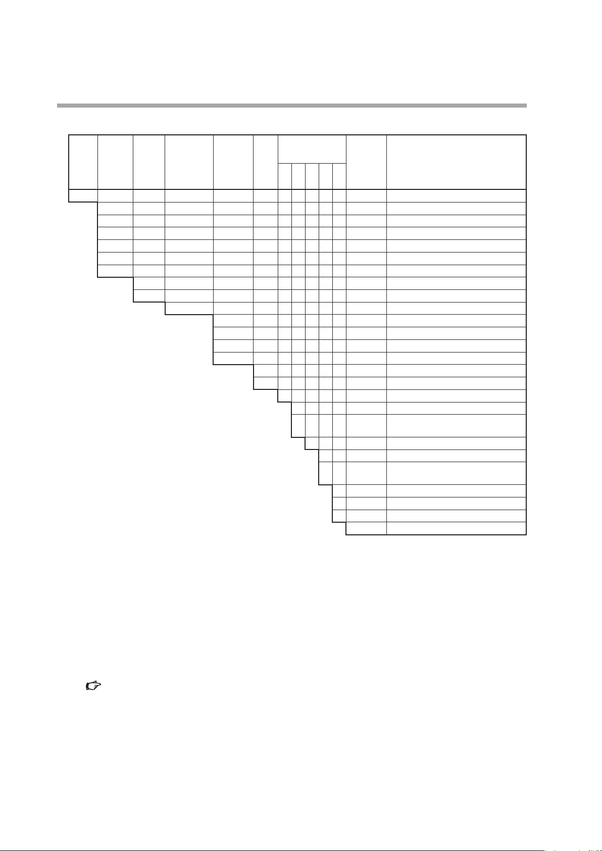
Model selection guide
MQV9005/9020
z
Chapter 1. INTRODUCTION
Standard
Basic
model
control
flowrate
No.
range
MQV Digital mass flow controller, MQV
9005 0.10 to 5.00 mL/min (standard)
9020 0.2 to 20.0 mL/min (standard)
Display
Material of
gascontacting
parts
B Integrated display (body length 90 mm)
C Separate display (body length 90 mm)
S SUS316
Connection
method
Gas
type
S 1/4" Swagelok
V 1/4" VCR
N Air, nitrogen
S Oxygen
Optional
functions
1 2 3 4 5
0 Without optional functions
0 Without optional functions
1 Model with RS-485 communications
0 Without optional functions
Appended
No.
(CPL) function
0 Without optional functions
1 Gas-contacting parts treated to be oil
0 Without optional functions
D With inspection certificate
Y With traceability certificate
0 Product version
free
*5
Description
*2, *4
*3, *4
*1, *4
*1, *4
*1. mL/min (standard) indicates the volumetric flow rate per minute (mL/min) converted to conditions of 20 ˚C and
101.325 kPa (1 atm). The reference temperature can be changed to 0, 25, or 35 ˚C.
*2. Air/nitrogen is the factory setting. By changing the setting, this model can be used for argon.
*3. Oxygen is the factory setting. By changing the setting, this model can be used for air/nitrogen, argon. However, once
this device has been used for gas other than oxygen, never reuse it for oxygen.
*4. The flow rate ranges in the table are for use of this device with air. The controllable flow range may vary depending
on the type of gas.
Gas type and control range (P.7-11).
*5. When oxygen is selected as the gas type, selection “1,” “gas-contacting parts treated to be oil free,” must be selected
for Optional function 4.
1-7
Chapter 1. INTRODUCTION
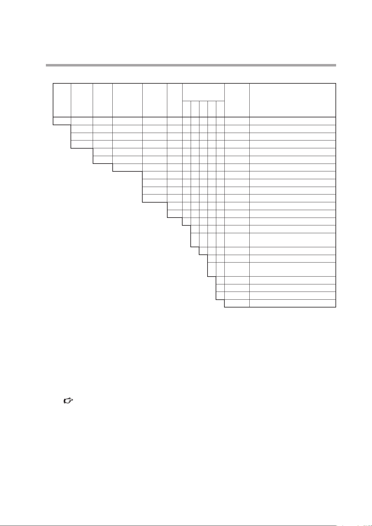
MQV9200/9500/0002/0005/0020/0050
z
Basic
model
No.
Standard
control
flowrate
range
Display
Material of
gascontacting
parts
Connection
method
Gas
type
Optional
functions
1 2 3 4 5
Appended
No.
Description
MQV Digital mass flow controller, MQV
9200 2 to 200 mL/min (standard)
*1, *4
9500 0.004 to 0.500 L/min (standard)
0002 0.02 to 2.00 L/min (standard)
0005 0.04 to 5.00 L/min (standard)
0020 0.2 to 20.0 L/min (standard)
0050 0.4 to 50.0 L/min (standard)
*1, *4
*1, *4
*1, *4
*1, *4
B Integrated display (body length 90 mm)
C Separate display (body length 90 mm)
S SUS316
R Rc 1/4"
S 1/4" Swagelok
V 1/4" VCR
U 9/16-18UNF
N Air, nitrogen
S Oxygen
*2, *4
*3, *4
0 Without optional functions
0 Without optional functions
1 Model with RS-485 communications
(CPL) function
0 Without optional functions
0 Without optional functions
1 Gas-contacting parts treated to be oil
*5
free
0 Without optional functions
D With inspection certificate
Y With traceability certificate
0 Product version
*1, *4
*1. L/min (standard) and mL/min (standard) indicate the volumetric flow rate per minute (L/min and mL/min) converted
to conditions of 20 ˚C and 101.325 kPa (1 atm). The reference temperature can be changed to 0, 25, or 35 ˚C.
*2. Air/nitrogen is the factory setting. By changing the setting, this model can be used for argon, carbon dioxide (CO
city gas 13A (LNG: 46 MJ/m
3
), city gas 13A (LNG: 45 MJ/m3), propane 100 %, methane 100 %, or butane 100 %.
Additionally, semi-standard gas models that can be used for ammonia or acetylene (seal material: EPDM) can also be
manufactured.
*3. Oxygen is the factory setting. By changing the setting, this model can be used for air/nitrogen, argon, carbon dioxide
(CO
), city gas 13A, propane 100 %, methane 100 %, or butane 100 %. However, once this device has been used for
2
gas other than oxygen, never reuse it for oxygen.
*4. The flow rate ranges in the table are for use of this device with air. The controllable flow range may vary depending
on the type of gas.
Gas type and control range (P.7-11).
*5. When oxygen is selected as the gas type, selection “1,” “gas-contacting parts treated to be oil free,” must be selected
for Optional function 4.
1-8
),
2
MQV0050(J, K)/0200/0500
z
Chapter 1. INTRODUCTION
Standard
Basic
model
control
flowrate
No.
range
MQV Digital mass flow controller, MQV
0050 0.4 to 50.0 L/min (standard)
0200 2 to 200 L/min (standard)
0500 4 to 500 L/min (standard)
Display
Material of
gascontacting
parts
J Integrated display (body length 150 mm)
K Separate display (body length 150 mm)
S SUS316
Connection
method
Gas
type
R Rc 1/2"
S 1/2" Swagelok
V 1/2" VCR
U 3/4-16UNF
N Air, nitrogen
S Oxygen
Optional
functions
1 2 3 4 5
0 Without optional functions
0 Without optional functions
1 Model with RS-485 communications
0 Without optional functions
Appended
No.
(CPL) function
0 Without optional functions
1 Gas-contacting parts treated to be oil
0 Without optional functions
D With inspection certificate
Y With traceability certificate
0 Product version
free
*5
Description
*1, *4
*1, *4
*2, *4
*3, *4
*1, *4, *6
*1. The notations mL/min (standard) and L/min (standard) indicate the volume flow rate per minute converted to 20 ˚C,
one atmosphere (101.3 kPa (abs)). The reference temperature can also be changed to 0 ˚C, 25 ˚C or 35 ˚C.
*2. Air/nitrogen is the factory setting. By changing the setting, this model can be used for argon, carbon dioxide (CO
city gas 13A (LNG: 46 MJ/m
3
), city gas 13A (LNG: 45 MJ/m3), propane 100 %, methane 100 %, or butane 100 %.
),
2
Additionally, semi-standard gas models that can be used for ammonia or acetylene (seal material: EPDM) can also be
manufactured. (MQV0200/0500 only)
*3. Oxygen is the factory setting. By changing the setting, this model can be used for air/nitrogen, argon, carbon dioxide
(CO
), city gas 13A (LNG: 45 MJ/m3), propane 100 %, methane 100 %, or butane 100 %. However, once this device has
2
been used for a gas other than oxygen, never reuse it for oxygen.
*4. The flow rate ranges in the above table are for use of this device for air. The controllable flow range may vary
depending on the type of gas.
Gas type and control range (P.7-11).
*5. When oxygen is selected as the gas type, selection “1,” “gas-contacting parts treated to be oil free,” must be selected
for Optional function 4.
*6. The MQV0050(J, K) is for low differential pressure and is controllable to a high flow rate range with lower differential
pressure than the MQV0050(B, C).
1-9
Chapter 1. INTRODUCTION
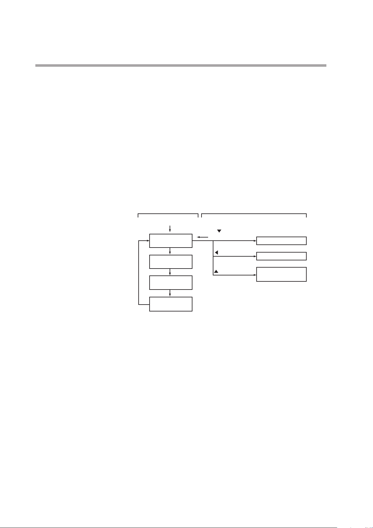
Basic operation Advanced operation
DISP key
Basic operation and advanced operation
This device provides two kinds of operations, basic operation and advanced
operation. Basic operation is the state of the device during normal use. In
basic operation, the contents of the 7-segment display can be changed to show
instantaneous flow rate, flow set value, totalized flow value, or amperage to the
valve in normal operation mode. Also, how to set the flow set value is described in
the basic operation part.
Advanced operation is for selecting various functions or setting parameters of the
device. When the device is used with the factory settings, no setup operation is
needed. However, to change the gas type, set a range, set an external contact input,
set upper and lower alarm limits, or set communication conditions (for models
with communication functions), it is necessary to configure various settings using
advanced operation. The diagram below gives an outline of operation flow. Basic
and advanced operation are described in Chapters 4 and 5, respectively.
Power ON
Instantaneous
ow rate display
DISP key
Flow set value
display
DISP key
Totalized ow
display
DISP key
Valve amperage
display
DISP key
key+ENT key
(3 s or more)
key (3 s or more)
key (3 s or more)
Function setup mode
Parameter setup mode
Controller information
display mode
1-10
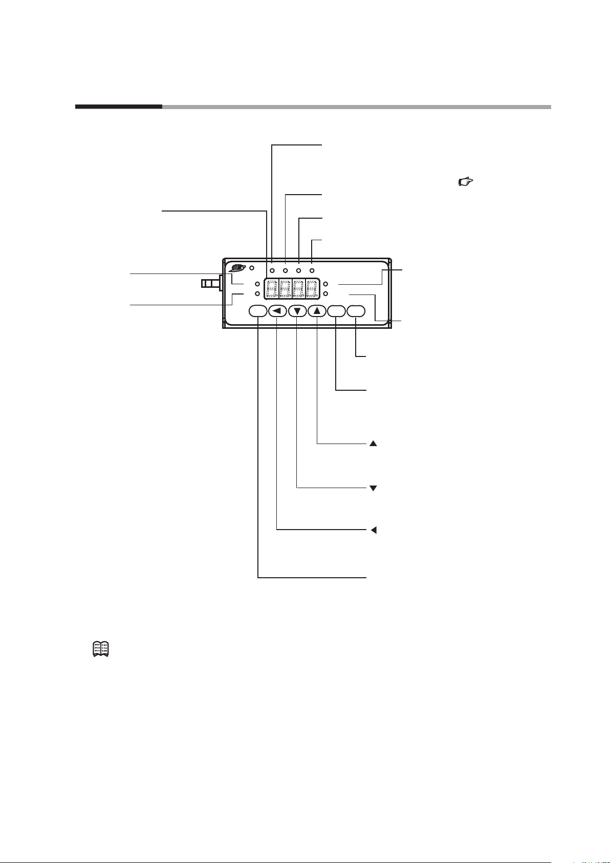
Chapter 2. NAMES AND FUNCTIONS OF PARTS
PV lamp:
OK lamp:
Use this key to change the operating mode.
reset alarm and move to the function setup mode.
Display
Lit when the deviation between the ow set value
and instantaneous ow rate is in the allowable range.
Set the allowable range in the parameter setup.
7-segment display:
Displays the instantaneous ow rate,
ow set value, totalized ow, amperage
to the valve and the operating mode.
It also displays parameter setup values, function
setup values and details of alarms.
SP lamp:
Lit when the ow rate
setpoint is displayed.
Lit when the instantaneous ow
rate is displayed.
ALM lamp:
Lit when an alarm occurs.
EV1 lamp
Lit when event 1 output is ON.
EV2 lamp:
Lit when event 2 output is ON.
OK ALM EV1 EV2
SP
PV
RUN ENT DISP
(For details on how to set parameters, )
:
L
L/min
Digital
Mass Flow
Controller
DISP key:
Use this key to switch the details displayed
on the 7-segment display.
ENT key:
Use this key to x and store the set value
to memory.
Also use it to reset the cumulative ow and to
L lamp
*1:
Lit when the totalized ow is
displayed.
Blinks when the cumulative
ow event occurs.
L/min lamp
Lit when the instantaneous ow rate
or ow set value is displayed.
P.5-11
*2:
Note
key:
Use this key to increment the setting value.
Additionally, this key is used to change to
the device information display mode.
key:
Use this key to decrement the setting value.
Also use it to move to the function setup mode.
key:
Use this key to move to a desired digit
when changing setting value. Also use it to
move to the parameter setup mode.
RUN key:
*1. This lamp is used for mL or m3 instead of L on some models.
*2. This lamp is used for mL/min instead of L/min on some models.
•
Technical terms used in this manual are defined as follows:
•
SP (setpoint): The flow set value (or flow rate setpoint)
•
PV (process variable): Instantaneous flow rate (or controlled flow rate)
•
Operating mode: 3 modes (valve fully closed/valve control/ valve fully
open)
2-1
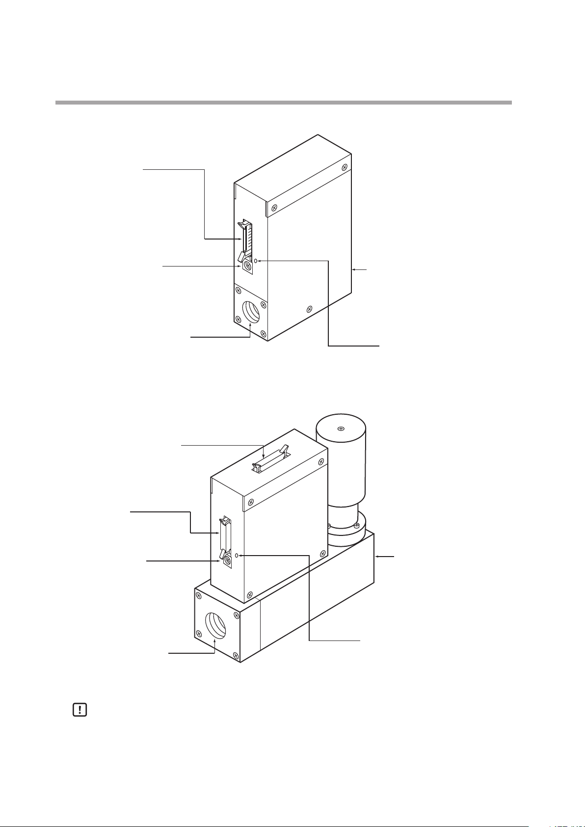
Chapter 2. NAMES AND FUNCTIONS OF PARTS
gas enters.
Jack for PC loader connection
Connector port:
This is used for I/O signals.
Use cable with dedicated
connector.
Jack for AC adapter:
Connect dedicated adapter here.
Model No.: 81446957-001
(24 V DC, 750 mA)
Pipe connection port (inlet):
This is the port through which
gas enters.
Pipe connection port (outlet):
Connector port:
This is used for I/O signals.
Use cable with dedicated
connector.
Connector for separate display:
This is used for connecting the
separate display unit.
Main unit (MQV9005/9020/9200/9500/0002/0005/0020/0050)
Jack for AC adapter:
Connect dedicated adapter here.
Model No.: 81446957-001
(24 V DC, 750 mA)
Pipe connection port (inlet):
This is the port through which
Main unit (MQV0050(J, K) /0200/0500)
Pipe connection port (outlet):
This is the port from which
gas is discharged.
2-2
Handling Precautions
This is the port from which
gas is discharged.
Jack for PC loader connection
•
The former AC adapter (model No. 81446682-001, 15 V DC/350 mA) can not be
used with MQV.
Chapter 3. MOUNTING AND WIRING
Never allow gases that are within explosive limits to pass through this device. Doing so might
result in an explosion.
If the MQV is to be used for oxygen, make sure that it is a model designed for oxygen use. Even
if a device is designed for oxygen gas, do NOT use it for oxygen gas if it has been used for some
other gas even once. Oil contained in another gas may be deposited on the gas-contacting
parts and ignite upon reacting with oxygen.
Prevent foreign matter from entering the device. If rust, water droplet, oil mist, or dust in the
pipes enters the device, measurement or control error or damage might occur.
If there is a possibility of foreign matter entering the device, provide a filter, strainer or mist
trap capable of eliminating foreign matter 0.1 µm or greater in diameter at the upstream. Be
sure to inspect and replace the filter at regular intervals.
Use the device within the operating differential pressure range. Also, do not subject it to
pressure beyond the rated pressure resistance range. Doing so might damage it.
Do not subject this device to pressure above its pressure resistance. Doing so might damage it.
Be sure to use within the flow-rate range stipulated in the product specifications.
To prevent excessive flow, use a suitable means to control the supply pressure or use a throttle
valve or the like to control the flow rate.
If the flow rate exceeds the upper limit, both the flow rate display and the output voltage/
current may indicate considerably lower values than the actual flow rate.
If damage could result from the abnormal functioning of this device, include appropriate
redundancy in the system design.
The valve on this device cannot completely shut a flow off. If complete shutoff is required,
provide a shutoff valve separately. When the external valve is closed, it is necessary also to
fully close the valve of the device using either of the following methods:
If this valve remains in normal control status when the external shutoff valve is closed (zero
flow rate), there will be an excessively large flow as soon as the external shutoff valve is
opened. For the MQV0050(J, K), MQV0200(J, K), and MQV0500(J, K), if the external shutoff
valve is closed continuously for 5 minutes or more in control mode or with the valve forced
fully open, the valve overheating limit (AL71) will be activated and the current to the valve will
be forcibly limited.
WARNING
CAUTION
•
Set the flow rate setpoint to zero.
•
Make the valve operation mode to fully closed.
3-1
Chapter 3. MOUNTING AND WIRING
Before connecting pipes with Swagelok or VCR connections, check the precautions in the
instruction provided by the connecting joint manufacturer.
When purchasing a connecting joint, use the following made by Swagelok Co., Ltd:
1/4" Swagelok: SS-400-1-6ST (standard)
1/2" Swagelok: SS-810-1-8ST (standard)
1/4" VCR: SS-4-VCR-1-00032SC11
1/2" VCR: SS-8-VCR-1-8STSC 11 or equivalent
When controlling oxygen flow, use an oxygen model and observe the following:
The device is a precision instrument. Do not drop it or subject it to impact, or it might be
damaged.
SS-400-1-6STSC11 (oil-inhibited)
SS-810-1-8STSC11 (oil-inhibited)
•
Piping should be carried out by a specialist skilled in handling oxygen gas.
•
Use oil-free pipes and parts.
•
Be sure to remove foreign matter, burrs, etc. from the pipes before connecting the device.
CAUTION
Mounting
Installation locations
z
Avoid mounting the device in the following locations:
•
Locations subject to high and low temperature and humidity
•
Locations whose atmospheres contain large amounts of dirt and dust, salt, conductive
substances such as iron powder, water droplet, oil mist or organic solvents
•
Locations subject to direct sunlight and rain
•
Locations directly subject to mechanical vibration or shock
•
Locations close to sources of electrical noise
•
Locations where strong magnetic or electrical fields are generated
Handling Precautions
•
The valve of this device cannot completely shut a flow off. If complete
shutoff is required, provide a shutoff valve separately.
Changing the display direction (models with integrated display only)
z
The display can be turned 180˚, in case the controller has been mounted with the
display upside-down.
3-2

Chapter 3. MOUNTING AND WIRING
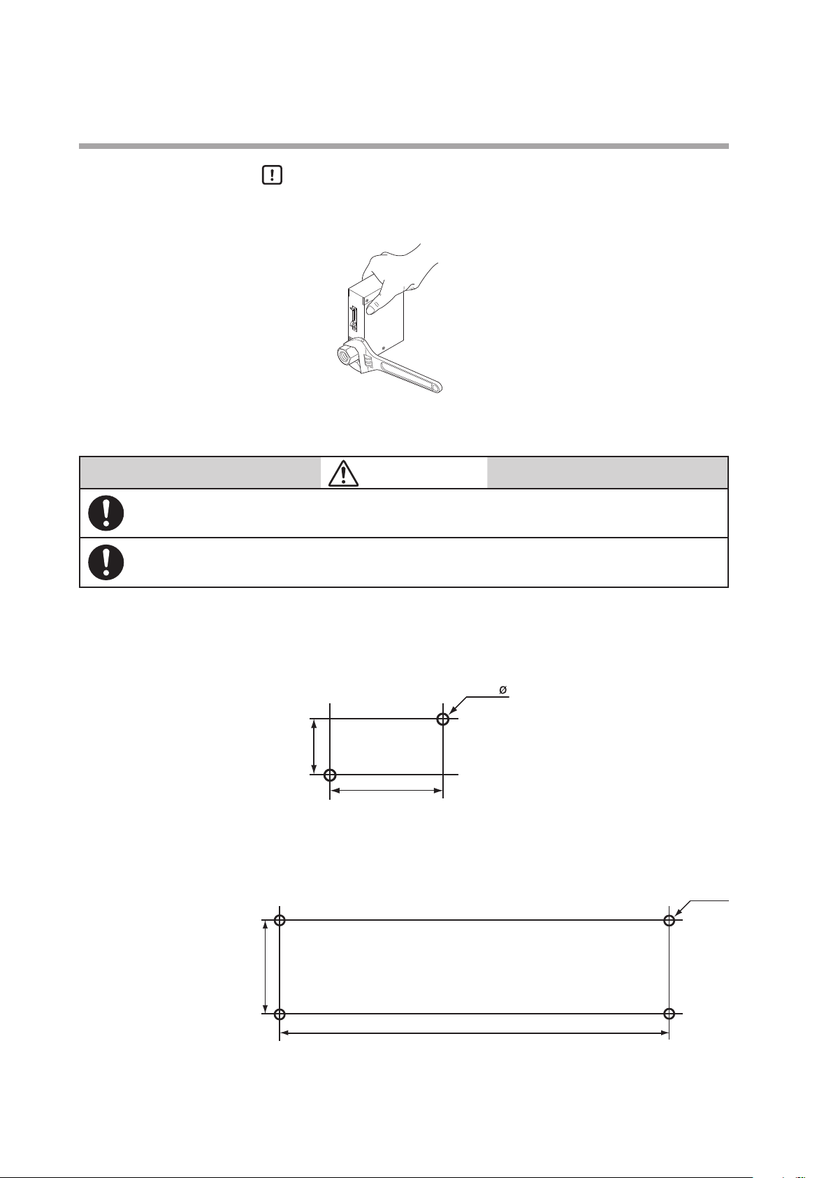
When installing joints (UNF connections), secure the lower part of the main unit in a vise or the
like gripped between rags to protect the finished surfaces, and turn the joint to tighten. The
device may be damaged if the lower main unit is not secured.
Connector latches
Main unit
•
Procedure
(1) Turn the power OFF.
(2) Remove the four screws holding the display.
(3) Lift up the display from the main unit, and turn it 180˚ counterclockwise.
(4) Put the display back on the main unit, and fasten with the four screws
(5) To return the display to its original position on the body, turn it 180˚
Handling Precautions
•
Before changing the display direction, be sure to turn the power OFF.
•
Prevent foreign objects from falling inside the main unit when the display
is taken off. Failure to do so might cause trouble or malfunction.
•
Do not remove the connectors used inside the main unit.
Installing joints (UNF) connections
z
taken off in step (2).
clockwise.
CAUTION
Rag
3-3
Chapter 3. MOUNTING AND WIRING
Incorrect
Mount securely in order to prevent vibration. Otherwise, equipment failure could result.
Mount the device horizontally. Do not mount it with the display facing down. Doing so might
cause measurement error or equipment failure.
15
4.5
27
4.5 ø
Installation procedure
z
Handling Precautions
•
Do not hold the top part of the main unit with your hand. Doing so might
deform the case.
•
Take special care not to damage the connector latches.
CAUTION
z MQV9200/9500/0002/0005/0020/0050
Install the device with two M4 screws using the mounting holes on the base of the
device.
z MQV0050(J, K)/0200/0500
Install the device with four M4 screws using the mounting holes on the base of the
device.
unit: mm
30
unit: mm
110
3-4
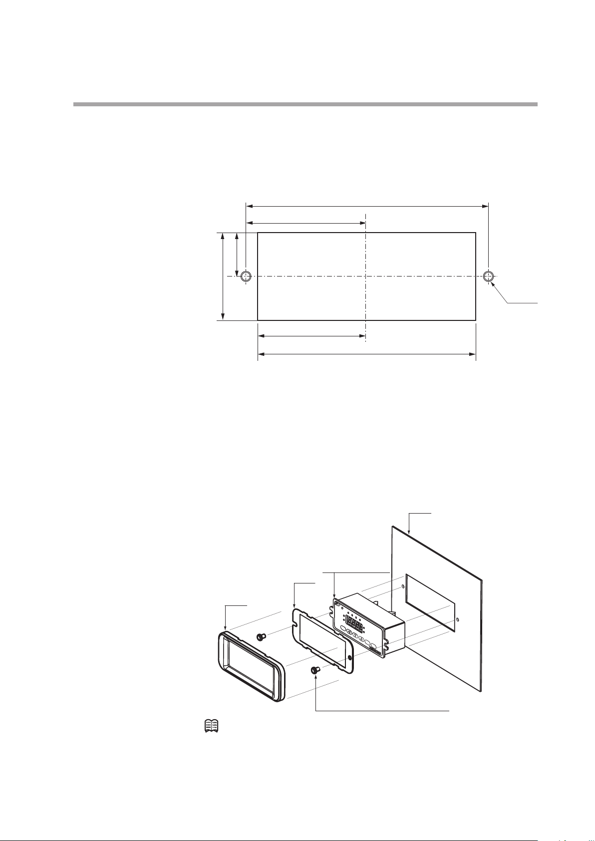
Installing the separate display unit
35 ±0.2
Panel cutout dimensions
(cross recessed head machine screws)
Panel
z
For models with a separate display
(1) Make mounting holes in the panel according to the panel cutout dimensions.
17.5 ±0.2
Chapter 3. MOUNTING AND WIRING
unit: mm
100 ±0.2
50 ±0.2
M4 (2)
45 ±0.2
(2) Mount the display and secure it by tightening the screws.
Installing the front cover for the separate display unit
z
For models with a separate display, a front cover (decorative frame) can be
mounted. Use of this cover makes it possible to hide the mounting screws,
improving the appearance.
Items needed for installation
• Front cover (81446858-001), 1 set
• Phillips screwdriver
Plate
Mask
90 ±0.2
Separate display
unit
Procedure
(1) As shown in the figure, put the plate over the display panel, and then secure it
(2) Fit the mask onto the display to mount it.
Mounting screws
Note
•
The front cover set includes one mask, one plate, and two mounting screws.
to the display by tightening the screws.
3-5
Chapter 3. MOUNTING AND WIRING
Mount this device horizontally. However, do not mount with the display facing down. Doing so
might cause measurement error or device failure.
For the MQV0050(J, K)/0200(J, K)/0500(J, K), use the largest pipe possible in order to reduce
pressure loss in the pipes, and do not install any equipment near the device that can cause
a large pressure loss. If there is a large pressure loss in the pipes or equipment, the pressure
of the gas supply to this device (operation differential pressure) will be affected and will
fluctuate greatly with the flow rate. This could result in unstable control.
When making the pipe connections, hold the hexagonal part of the connector section and turn
the pipe to tighten. After connecting, check that there are no gas leaks.
If using Rc connections, take care not to coat with too much sealant. Foreign matter or burrs in
the pipes may also cause measurement errors.
Correct
Incorrect
Sealant
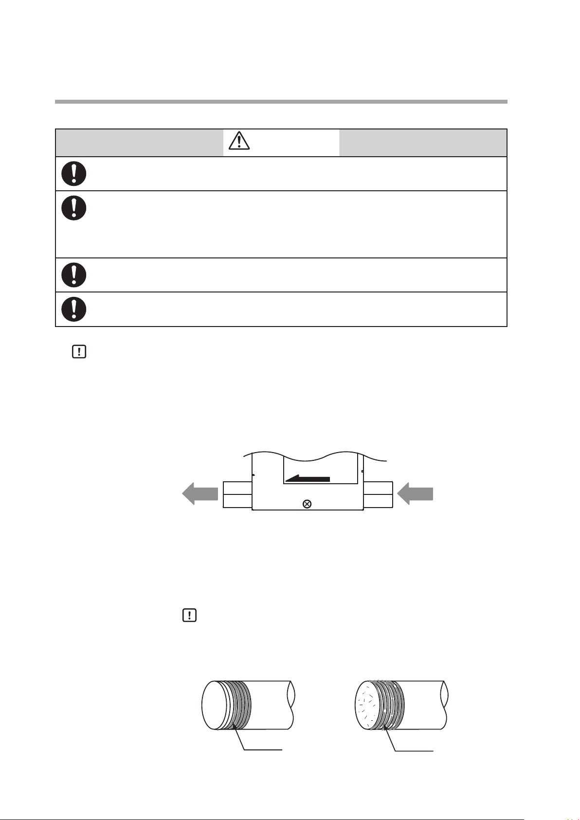
Piping
CAUTION
Handling Precautions
•
Make sure that the gas flows into the device in the direction indicated by the
FLOW arrow on the main unit. Otherwise, the flow rate cannot be controlled
correctly.
•
Do not touch the pipe sections of a controller treated to be oil-free with your
bare hands. Doing so will degrade the oil-free treatment.
•
Do not hold the top part of the main unit with your hand when connecting
piping. Doing so might deform the case.
Fasten and connect pipes to the body using a wrench (spanner) or similar tool on
the hexagonal sections of the joints.
Coating sealant (Rc connection)
z
Handling Precautions
•
FLOW
GasGas
Coat with an appropriate amount of sealant. Do not coat the top two
threads. Remove any dirt or burrs from inside the pipes.
3-6
Sealant
Wiring
Do not apply a negative voltage or a voltage exceeding 5 V to the external setup voltage input
terminal. Doing so might cause malfunction or equipment failure.
When using a relay for external contact input and/or external 3-way switching input, always
use a relay designed for micro-current use (with gold contacts). Failure to do so could cause
faulty contact, resulting in malfunction.
If there is a risk of a power surge caused by lightning, use a surge protector to prevent fire or
equipment failure.
Gas type switching by external contact input, flow rate switching, and analog input/output
voltage range switching by external 3-way input switching should be done only after setting
the operation mode to fully closed. Switching while controlling could cause large fluctuations.
Be sure to check that the wiring is correct before turning the power on. Incorrect wiring could
cause damage or malfunction.
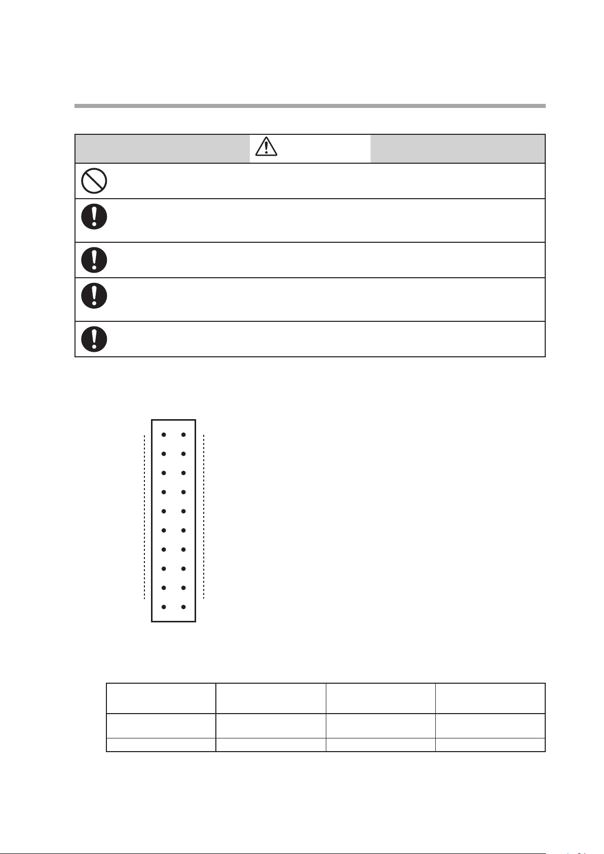
View from connector insertion side
Chapter 3. MOUNTING AND WIRING
CAUTION
Connector pin layout
z
Connector model No. (device side): HIF3BA-20PA-2.54DS
20 19
2
Table of compatible connectors (all made by HIROSE ELECTRIC CO., LTD.)
z
1
Manufacturer: HIROSE ELECTRIC CO., LTD.
Connector type
Contact crimp type HIF3BA-20D-2.54C HIF3-2226SCC AWG#22 to #26
Cable clamp type HIF3BA-20D-2.54R Not required AWG#28 (flat cable only)
Compatible connector
model No.
Compatible contact
model No.
Compatible wire
(single wire allowed)
3-7
 Loading...