

Page 1
™
Digital Mass Flow Controller
Standard Gas Model
MQV9005/9020/9200/9500
0002/0005/0020/0050/0200/0500
User’s Manual
No. CP-SP-1204E
Thank you for purchasing an Azbil
Corporation product.
This manual contains information for
ensuring the correct use of this product.
It also provides necessary information
for installation, maintenance, and
troubleshooting.
This manual should be read by those who
design and maintain equipment that uses
this product. Be sure to keep this manual
nearby for handy reference.
Page 2

IMPORTANT
“Natural gas” in this document refers to city gas in Japan.
NOTICE
Be sure that the user receives this manual before the product is used.
Copying or duplicating this user’s manual in part or in whole is forbidden.
The information and specifications in this manual are subject to change
without notice.
Considerable effort has been made to ensure that this manual is free from
inaccuracies and omissions. If you should find an error or omission, please
contact the azbil Group.
In no event is Azbil Corporation liable to anyone for any indirect, special or
consequential damages as a result of using this product.
© 2006-2018 Azbil Corporation All Rights Reserved.
Micro Flow™, µF™ are trademarks of Azbil Corporation in Japan.
Page 3
Conventions Used in This Manual
The safety precautions explained in the following section aim to prevent injury to the operator and others, and to
prevent property damage.
Warnings are indicated when mishandling this product
WARNING
CAUTION
In describing the product, this manual uses the icons and conventions listed below.
Use caution when handling the product.
The indicated action is prohibited.
Always follow the indicated instructions.
might result in death or serious injury.
Cautions are indicated when mishandling this product
might result in minor injury to the user, or physical damage
to the product.
Handling Precautions:
Handling Precautions indicate items that the user should pay attention to when handling
the product.
Note:
(1)(2)(3): Numbers within parentheses indicate steps in a sequence or parts of an explanation.
0FF
>>: Indicates the result of an operation, details displayed on the personal computer or other
Notes indicate information that might benefit the user.
This indicates the item or page that the user is requested to refer to.
Indicates a selectable button on a personal computer screen.
devices, or the state of the device after operation.
ii
Page 4
Safety Precautions
Never allow gases that are within explosive limits to pass through this device. Doing so might
result in an explosion.
If the MQV is to be used for oxygen, make sure that it is a model designed for oxygen use.
Even if a device is designed for oxygen gas, do NOT use it for oxygen gas if it has been used
for some other gas even once. Oil contained in another gas may be deposited on the gascontacting parts and ignite upon reacting with oxygen.
If the device is used for burner air-fuel ratio control, take the necessary countermeasures
with the equipment to prevent the occurrence of backfire and to avoid any influence to the
device even if backfire occurs. Pressure increase or fire in the pipes caused by the backfire of
the burner could damage the controller.
This device cannot be used for measurement or control of hydrogen or helium gas. Use a
model specially designed for hydrogen and helium gases. For information on whether this
device can be used for gases other than the standard compatible gases, be sure to contact
the azbil Group in advance.
Prevent foreign matter from entering the device. If rust, water droplet, oil mist, or dust in the
pipes enters the device, measurement or control error or damage might occur.
If there is a possibility of foreign matter entering the device, provide a filter, strainer or mist
trap capable of eliminating foreign matter 0.1 µm or greater in diameter at the upstream. Be
sure to inspect and replace the filter at regular intervals.
Use this device within the operating differential pressure range. Not doing so may cause
hunting. Continuous hunting could damage the valve.
WARNING
CAUTION
Do not subject this device to pressure above its pressure resistance. Doing so might damage
it.
Be sure to use within the flow-rate range stipulated in the product specifications.
To prevent excessive flow, use a suitable means to control the supply pressure or use a
throttle valve or the like to control the flow rate.
If the flow rate exceeds the upper limit, both the flow rate display and the output voltage/
current may indicate considerably lower values than the actual flow rate.
If damage could result from the abnormal functioning of this device, include appropriate
redundancy in the system design.
iiii
Page 5
CAUTION
The valve on this device cannot completely shut a flow off. If complete shutoff is required,
provide a shutoff valve separately. When the external valve is closed, it is necessary also to
fully close the valve of the device using either of the following methods:
•
Set the flow rate setpoint to zero.
•
Make the valve operation mode to fully closed.
If this valve remains in normal control status when the external shutoff valve is closed (zero
flow rate), there will be an excessively large flow as soon as the external shutoff valve is
opened. For the MQV0050(J, K), MQV0200(J, K), and MQV0500(J, K), if the external shutoff
valve is closed continuously for 5 minutes or more in control mode or with the valve forced
fully open, the valve overheating limit (AL71) will be activated and the current to the valve
will be forcibly limited.
Before connecting pipes with Swagelok or VCR connections, check the precautions in the
instruction provided by the connecting joint manufacturer.
When separately purchasing a connecting joint, use the following made by Swagelok Co.,
Ltd:
1/4” Swagelok: SS-400-1-6ST (standard)
SS-400-1-6STSC11 (oil-inhibited)
1/2” Swagelok: SS-810-1-8ST (standard)
SS-810-1-8STSC11 (oil-inhibited)
1/4” VCR: SS-4-VCR-1-00032SC11
1/2” VCR: SS-8-VCR-1-8STSC11 or equivalent
Observe the following when using the device (oil-free model) for oxygen gas:
•
Piping should be carried out by a specialist skilled in handling oxygen gas.
•
Use oil-free pipes and parts.
•
Be sure to remove foreign matter, burrs, etc. from the pipes before connecting the device.
The device is a precision instrument. Do not drop it or subject it to impact, or it might be
damaged.
When installing joints (UNF connections), secure the lower part of the main unit in a vise or
the like gripped between rags to protect the finished surfaces, and turn the joint to tighten.
Mount securely in order to prevent vibration. Otherwise, equipment failure could result.
Mount the device horizontally. Do not mount it with the display facing down. Doing so might
cause measurement error or equipment failure.
For the MQV0050(J, K)/0200(J, K)/0500(J, K). use the largest pipe possible in order to reduce
pressure loss in the pipes, and do not install any equipment near the MQV that can cause a
large pressure loss. If there is a large pressure loss in the pipes or equipment, the pressure
of the gas supply to this device (operation differential pressure) will be affected and will
fluctuate greatly with the flow rate. This could result in unstable control.
When making the pipe connections, hold the hexagonal part of the connector section and
turn the pipe to tighten. After connecting, check that there are no gas leaks.
iiiiii
Page 6
CAUTION
If using Rc connections, take care not to coat with too much sealant. Foreign matter or burrs
in the pipes may also cause measurement errors.
Do not apply a negative voltage or a voltage exceeding 5 V to the external setup voltage
input terminal. Doing so might cause malfunction or equipment failure.
When using a relay for external contact input and/or external 3-way switching input, always
use a relay designed for micro-current use (with gold contacts). Failure to do so could cause
faulty contact, resulting in malfunction.
If there is a risk of a power surge caused by lightning, use a surge protector to prevent fire or
equipment failure.
Gas type switching by external contact input, flow rate switching, and analog input/output
voltage range switching by external 3-way input switching should be done only after
setting the operation mode to fully closed. Switching while controlling could cause large
fluctuations.
Be sure to check that the wiring is correct before turning the power on. Incorrect wiring could
cause damage or malfunction.
Do not apply excessive force to the cables or connector while the connector cable or the AC
adapter is connected. Doing so may damage the connector or the circuit board.
Do not operate the console keys using a sharp object such as a mechanical pencil or
screwdriver. Doing so might damage the console.
When discarding the device, dispose of it as industrial waste, following local regulations.
iviv
Page 7
The Role of This Manual
A total of 2 different manuals are available for the MQV. Read them as necessary for your specific requirements. If a
manual you require is not available, contact the azbil Group or its dealer.
Digital Mass Flow Controller Standard Gas Model
MQV9005/9020/9200/9500/0002/0005/0020/0050/0200/0500
Manual No. CP-SP-1204E
This manual.
First-time users of the MQV, and those in charge of maintenance or hardware design for
incorporating a MQV controller in instrumentation should read this manual.
This manual outlines the product, tells how to install, wire, and incorporate the product
into instrumentation, and describes its operation, inspection and maintenance,
troubleshooting, and hardware specifications.
MQV9005/9020/9050/9200/9500/0002/0005/0010/0020/0050/0100/0200/0500
Digital Mass Flow Controller User’s Manual for Communication Functions
Manual No. CP-SP-1197E
Personnel who use this device’s communications functions should read this
manual. The manual gives an overview of communications, describes wiring,
transmission protocols, communications data, and troubleshooting, and gives
communications specifications.
vv
Page 8

Organization of This User’s Manual
This manual is organized as follows.
Chapter 1. INTRODUCTION
This chapter briefly describes this device and its features, and gives a model
selection guide.
Chapter 2. NAMES AND FUNCTIONS OF PARTS
This chapter describes the names and functions of this device’s parts.
Chapter 3. MOUNTING AND WIRING
This chapter describes installation, mounting, wiring and initial settings of this
device.
Chapter 4. BASIC OPERATION
This chapter gives the basis of how to operate this device.
Chapter 5. ADVANCED OPERATION
This chapter describes how to set functions, parameters, controller information
display, and flow rate range.
Chapter 6. MAINTENANCE AND TROUBLESHOOTING
This chapter describes how to investigate and remedy trouble that may occur
during operation of this device.
Chapter 7. SPECIFICATIONS
This chapter describes the device’s specifications and external dimensions.
vivi
Page 9

Contents
Conventions Used in This Manual
Safety Precautions
The Role of This Manual
Organization of This User’s Manual
Chapter 1. INTRODUCTION
Introduction ...................................................................................................................................................... 1-1
Features ............................................................................................................................................................... 1-1
Functions ............................................................................................................................................................ 1-2
Model selection guide .................................................................................................................................. 1-7
Basic operation and advanced operation .........................................................................................1-10
Chapter 2. NAMES AND FUNCTIONS OF PARTS
Display ................................................................................................................................................................. 2-1
Main unit (MQV9005/9020/9200/9500/0002/0005/0020/0050) ............................................. 2-2
Main unit (MQV0050(J, K) /0200/0500) ................................................................................................ 2-2
Chapter 3. MOUNTING AND WIRING
Mounting ............................................................................................................................................................ 3-2
Piping.................................................................................................................................................................... 3-6
Wiring ................................................................................................................................................................... 3-7
Chapter 4. BASIC OPERATION
4 - 1 Switching Displays .............................................................................................................................................. 4-1
Basic operation ................................................................................................................................................ 4-1
4 - 2 Setting the Flow Rate ......................................................................................................................................... 4-4
Digital flow rate setup .................................................................................................................................. 4-5
Flow rate setup by external contact input (Advanced use) ........................................................ 4-7
Flow rate setup by external 3-way switching input (Advanced use) .....................................4-8
Analog flow rate setup ................................................................................................................................. 4-9
4 - 3 Selecting the Operating Mode ....................................................................................................................4-10
Operating mode selection ........................................................................................................................4-10
Operating mode display ............................................................................................................................4-10
Chapter 5. ADVANCED OPERATION
Setup mode transition operation ........................................................................................................... 5-1
5 - 1 Functions ................................................................................................................................................................. 5-2
Setup method ................................................................................................................................................... 5-2
Function setup items.....................................................................................................................................5-3
5 - 2 Parameters ............................................................................................................................................................5-11
Setup method .................................................................................................................................................5-11
Parameter setup item list ..........................................................................................................................5-12
viivii
Page 10

5 - 3 Device Information Display ......................................................................................................................... 5-15
Setup method ................................................................................................................................................ 5-15
Device information display item .......................................................................................................... 5-16
5 - 4 Flow Rate Range Change Function and Settings and Display Resolutions After
Change of Range ............................................................................................................................................... 5-17
Setup resolution in the analog setup................................................................................................. 5-18
Chapter 6. MAINTENANCE AND TROUBLESHOOTING
Alarm code display ......................................................................................................................................... 6-1
Troubleshooting guide ................................................................................................................................6-2
Chapter 7. SPECIFICATIONS
Specifications ...................................................................................................................................................7-1
Gas type and control range ..................................................................................................................... 7-11
Relationship between differential pressure and flow rate ..................................................... 7-12
Optional parts (sold separately) ........................................................................................................... 7-14
External dimensions ................................................................................................................................... 7-15
viii
Page 11
Chapter 1. INTRODUCTION
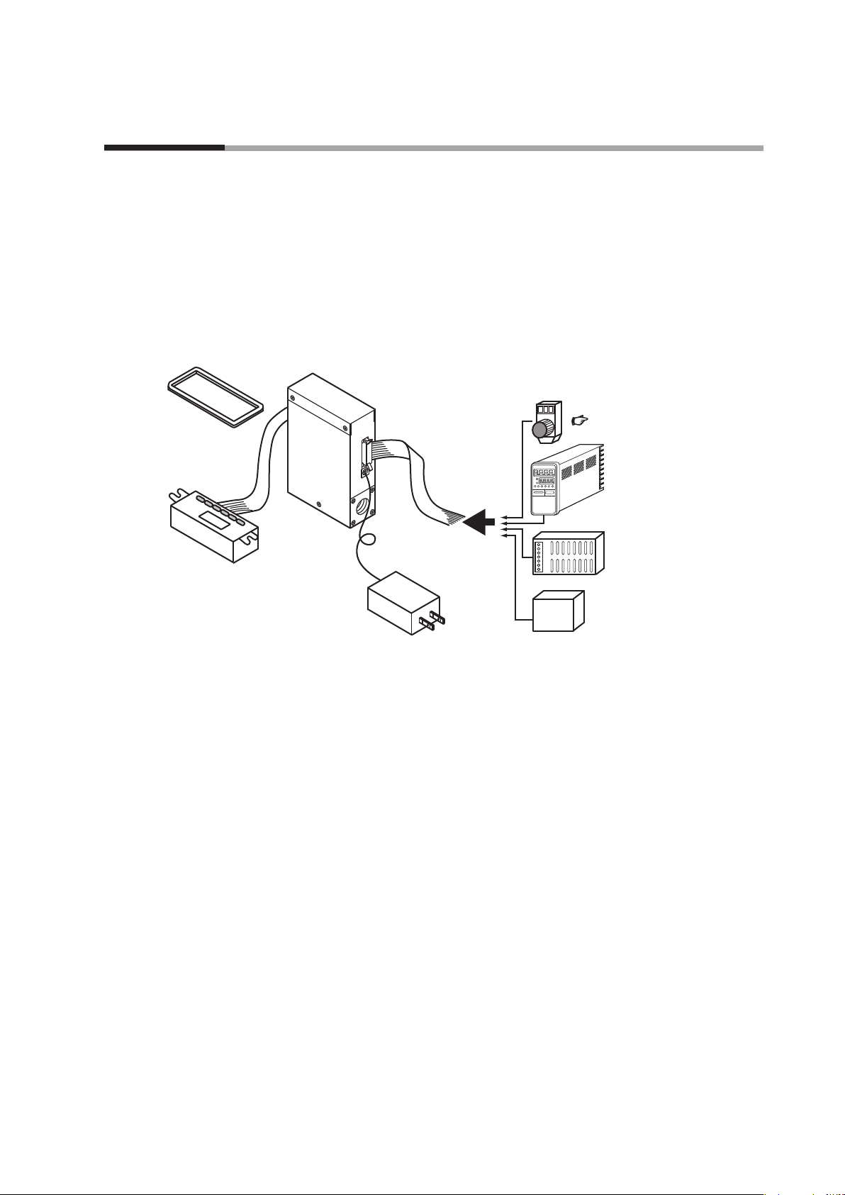
function)
Potentiometer (sold separately)
Separate display unit
Front cover for
Introduction
MQV high performance, digital mass flow controllers with advanced functions have
been developed for the general industrial application. They feature flow rate control
with high speed and wide rangeability. MQV controllers integrate three component
technologies: the ultra quick response µF (Micro Flow) thermal flow sensor, made
with proprietary Azbil Corporation technology, a proportional solenoid valve, and
advanced actuator control technology. Integrating these technologies has achieved
a high-speed control with low differential pressure.
separate display
(sold separately)
MQV
Features
Cable with dedicated
connector (sold separately)
AC adapter
(sold separately)
for setting ow rate
P.7-14
Controller
(e.g. SDC25/26)
24 V DC power supply
(e.g. WN790A)
RS-485 device
(for models supporting
optional RS-485
communications
Device Configuration
• High-speed controllability
Fast response of 300 ms or less*
(500 ms for the MQV9005/9020, 700 ms for the MQV0050(J, K), MQV0200, and
MQV0500.)
* Response time is the time required for the controlled flow rate to reach ±2 % of the
set value, starting from the fully closed state or from when the set value is changed
during control.
• Low differential pressure operation
MQV controllers can operate at a low differential pressure of 50 kPa or less.
• Wide control range
Wide control range of 1 to 100 % FS (2 to 100 % FS for the MQV9005)
• Wide product line-up
There are two types of models, those with integrated display and those with
separate display. On models with separate display, the display unit can be
detached to allow remote operation via the dedicated 2 m cable.
1-1
Page 12

Chapter 1. INTRODUCTION
• User-friendly
Runs on a general-purpose 24 V DC power supply, and the MQV's internal
power circuit and input/output circuits are isolated. When multiple MQV are
driven through the analog inputs and outputs, as with a PLC, they can all use
a common power supply even if the PLC's analog modules are not isolated by
channel. Therefore, even without individual power supplies for each device,
problems with one circuit do not affect adjacent ones. Also provided is a handy
AC adapter (sold separately) for easy use in the laboratory.
• Display direction can be changed (models with integrated display only)
The direction of the display can be rotated 180˚ to match the direction of the gas
flow, in case it was mounted the other way.
• Improved design (separate display model)
A front cover (sold separately) hides the mounting screws of the separate display
on the panel surface and improves the appearance.
Functions
• Various additional functions
The functions listed below are all standard.
All MQV models have the functions described below.
For function setup, Chapter 5. ADVANCED OPERATION.
• Multi-setup (function setup C-04)
Quickly switch to one of eight preset flow set value by key operation or external
input. If “Switching of SP No.” is set to external 3-way switching input, up to
three set values can be switched.
• Gas type switching (function setup C-18, C-26)
The gas type to be used can be selected from the standard compatible gases by
key operation. Additionally, two kinds of gas type settings can be changed by
external contact input.
• Gas type setup (function setup C-18)
The user can set gas type conversion factors for gases other than the standard
compatible gases, and for mixed gases.
For information on gas type conversion factors for various gases, contact the
azbil Group.
1-2
• Control flow range setting (function setup C-24, C-25)
The control flow range can be changed to the desired range (10 to 100 % of
the flow range at factory setting) in units of 1 % FS. The setup and display
resolution levels can be improved by reducing the control flow range.
Additionally, two kinds of control flow ranges can be switched through external
contact input.
• Direct setup (function setup C-2 1)
When changing the flow set value by key input, the controlled flow rate can
follow the set value while changes are being made (the flow set value can be
changed quickly). This function is useful when the user frequently changes set
value, for example when adjusting the flow set value during a trial run.
Page 13

Chapter 1. INTRODUCTION
• SP ramp control (function setup C-27)
This function is used to set the set value change ramp amount (the rate of
change per second) to a constant value for the start of control and for set value
changes. With this function, the set value change ramp amount can be set more
precisely than with the slow start function. Two different types of ramps can be
set, and there are the following 2 control modes:
•
SP ramp control 1
In SP ramp-up: Ramp 1
In SP ramp-down: Ramp 2
•
SP ramp control 2
In external contact OFF: Ramp 1
In external contact ON: Ramp 2
• SP limit (function setup C-35)
The lower and upper limits of the set value range can be set to desired levels.
(This prevents mistaken high/low settings.)
• Slow start (function setup C-1 7)
Sudden changes in the controlled flow rate, when control is started or when the
set value is changed, can be suppressed. The control speed can be changed in
eight stages within a range of about 1 to 6 seconds.
• Flow rate totalization (function setup C-09 to C-12)
MQV9005: in 0.1 mL units
MQV9020: in 1 mL units
MQV9200/9500: in 0.01 L units
MQV0002/0005: in 0.1 L units
MQV0020/0050: in 1 L units
MQV0050(J, K): in 0.001 m
MQV0200/0500: in 0.01 m3 units
Integrated flow count can be up to eight digits long (to 99,999,999) for each
unit. (Display alternates between first and last 4 digits.) The count can be
reset by key operation or external contact input. Use of external contact input
makes it possible to remotely operate the start, temporary stop, and reset of
totalization. When resetting the integrated count by key operation, the count
restarts automatically after it has been reset. On the other hand, when resetting
with the external contact input (by contact ON), the count restarts when the
contact is turned OFF.
3
units
• Event lamp lighting/output (function setup C-07, C-08)
Two of the event types listed below can be selected. Output ON delay time can
also be set (but delay cannot be set for totalizer pulse output).
•
Integrated flow event output (when the integrated flow event setting is
exceeded.)
•
Totalized pulse output (pulse can be output for each totalizing flow display
unit.)
•
OK output (the control flow rate is within the set value ± allowable range.)
1-3
Page 14

Chapter 1. INTRODUCTION
•
Flow rate upper or lower limit output (output in comparison with optional
upper or lower limit flow rate set value )
•
Output mode (The four modes — control / fully open / control or fully open /
fully closed — can be identified and output.)
• OK lamp ON/output (function setup C-07, C-08)
The OK lamp can be set to light when the control flow rate is within the set
value ± allowable range. This function is very handy for verifying at a glance
whether or not there is a proper response to a new set value after its value is
changed. OK lamp output can also be used as an interlock signal for subsequent
processes by assigning it to event output and including it in a sequence program.
• PV filter (function setup C-23)
This function is used to average the instantaneous flow rate (control flow rate)
detected value. Use of this function makes it possible to suppress effects of slight
pressure fluctuations.
• Control dead band setup (prevention of valve operation) (function setup
C-22)
This function is used to stop the valve from driving as long as the control flow
rate is within the OK range. Additionally, the OK range (width of dead band)
can be set to the desired level.
• Valve amperage display (function setup C-20)
The electric current supplied to the valve can be displayed in units of 0.0 to
100.0 %. Additionally, use of the valve amperage alarm detection function
makes it possible to detect an inlet pressure change or clogging of the piping at
the outlet.
• Gas type external switching (function setup C-10 to C-12, C-18, C-26)
Two preset types of gases (including one with a user-determined gas type
conversion factor) can be switched by external contact input.
• Control flow rate range external switching (function setup C-10 to C-12,
C-24, C-25)
Two preset control flow ranges can be switched by external contact input.
• PV forced zero (function setup C-29)
This function forcibly sets the detected instantaneous flow rate to 0 (zero) after
the delay time elapses when the flow rate setpoint has been set to 0 (zero) or the
valve mode has been changed to fully closed. This function makes it possible
to ignore the deviation of the instantaneous flow rate zero point caused by
inclination of the piping or the like.
1-4
• Flow rate display unit change (function setup C-37)
This function is used to change the flow rate display unit to L/min or mL/min of
the MQV9200/9500/0002/0005. When multiple devices are used side-by-side,
this function can make the flow rate display units uniform.
Page 15

Chapter 1. INTRODUCTION
• PV display decimal point change (function setup C-38)
This function is used to shift the decimal point position of the instantaneous
flow rate display one digit left or right. When multiple devices are used side-byside, the number of digits after the decimal point of the flow rate display can be
made uniform.
• Valve forcibly open or close (function setup C-02, C-09 to C-12)
This function is used to forcibly open or close the valve fully by key operation,
external contact input, or external 3-way switching input.
• Automatic shut-off (function setup C-13, C-16)
The valve can be shut off automatically under the following conditions:
•
When the totalized flow count reaches the preset value.
•
When one of the alarms, including flow rate alarms, is triggered.
• ALM (alarm) lamp ON/output/valve shut-off (function setup C-15, C-16 C-20)
The alarm output can be set for high and low deviations in the flow set value
and instantaneous flow rate. Additionally, an alarm judgment delay time can
also be set. If a flow rate alarm occurs or if an alarm occurs during self-diagnosis
of this controller, the valve can be forced fully closed or opened.
Handling Precautions
•
The valve on this device cannot completely shut off.
•
If complete shutoff is required, provide a shutoff valve separately.
• Automatic reset of cumulative count at start of control function (function
setup C-14)
Start of control and reset of totalized flow count can be done simultaneously by
a single action (by key or external switching input). Combining this function
with the automatic shut-off function described above is handy for shutting the
valve off in cases where a fixed totalized flow amount is counted repeatedly.
• Analog scaling (function setup C-28)
This function is used to optionally change the flow rate (between 10 % FS and
100 % FS) corresponding to 100 % FS analog input/output (5 V or 20 mA).
• Analog input (flow set value) range selection (function setup C-05, C-09)
In analog setup, the desired input range can be selected from those shown below
either by key operation or by external 3-way switching input. When doing so,
the voltage input and current input are selected automatically, as they are linked
with the settings of function setup C-06 (analog output type selection). For
example, when the voltage output (0 to 5 V or 1 to 5 V) is selected in C-06,
the voltage input is selected automatically. Likewise, when the current output
(0 to 20 mA or 4 to 20 mA output) is selected, the current input is selected
automatically.
1-5
Page 16

Chapter 1. INTRODUCTION
•
Internal reference 0 to 5 V input*/External reference 0 to 20 mA input
•
External reference 0 to 5 V input/External reference 0 to 20 mA input
•
External reference 1 to 5 V input/External reference 4 to 20 mA input
* The internal reference 0 to 5 V is used when the 5 V output terminal voltage
(pin No. 20) of this controller is used as the reference.
• Analog output type/range selection (function setup C-06, C-09)
Output can be set either to instantaneous flow rate (PV) or flow set value (SP).
Furthermore, a voltage/current output range can be selected from (1) to (4)
shown below by key operation. Additionally, (1)/(2) or (3)/(4) can be changed
through the external 3-way switching input. (Combinations are switched
because of linkage with the analog input range selection.)
Instantaneous flow rate (PV) output Flow set value (SP) output
(1) 0 to 5 V output
(1) 0 to 5 V output
(2) 1 to 5 V output
(3) 0 to 20 mA output
(4) 4 to 20 mA output
(2) 1 to 5 V output
(3) 0 to 20 mA output
(4) 4 to 20 mA output
1-6
Page 17
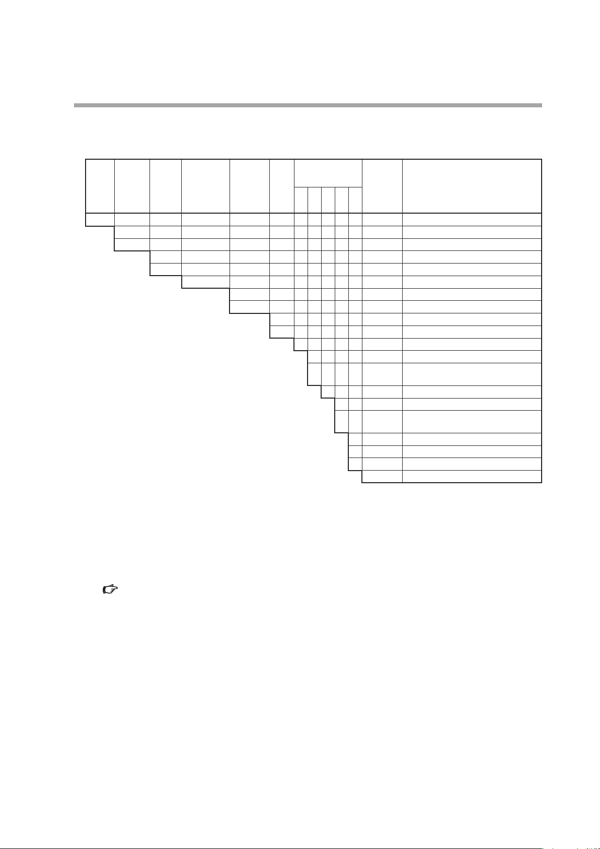
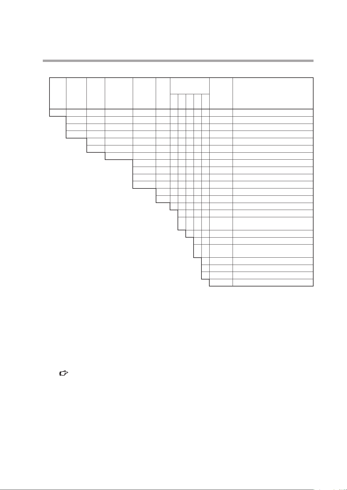
Model selection guide
MQV9005/9020
z
Chapter 1. INTRODUCTION
Standard
Basic
model
control
flowrate
No.
range
MQV Digital mass flow controller, MQV
9005 0.10 to 5.00 mL/min (standard)
9020 0.2 to 20.0 mL/min (standard)
Display
Material of
gascontacting
parts
B Integrated display (body length 90 mm)
C Separate display (body length 90 mm)
S SUS316
Connection
method
Gas
type
S 1/4" Swagelok
V 1/4" VCR
N Air, nitrogen
S Oxygen
Optional
functions
1 2 3 4 5
0 Without optional functions
0 Without optional functions
1 Model with RS-485 communications
0 Without optional functions
Appended
No.
(CPL) function
0 Without optional functions
1 Gas-contacting parts treated to be oil
0 Without optional functions
D With inspection certificate
Y With traceability certificate
0 Product version
free
*5
Description
*2, *4
*3, *4
*1, *4
*1, *4
*1. mL/min (standard) indicates the volumetric flow rate per minute (mL/min) converted to conditions of 20 ˚C and
101.325 kPa (1 atm). The reference temperature can be changed to 0, 25, or 35 ˚C.
*2. Air/nitrogen is the factory setting. By changing the setting, this model can be used for argon.
*3. Oxygen is the factory setting. By changing the setting, this model can be used for air/nitrogen, argon. However, once
this device has been used for gas other than oxygen, never reuse it for oxygen.
*4. The flow rate ranges in the table are for use of this device with air. The controllable flow range may vary depending
on the type of gas.
Gas type and control range (P.7-11).
*5. When oxygen is selected as the gas type, selection “1,” “gas-contacting parts treated to be oil free,” must be selected
for Optional function 4.
1-7
Page 18

Chapter 1. INTRODUCTION
MQV9200/9500/0002/0005/0020/0050
z
Basic
model
No.
Standard
control
flowrate
range
Display
Material of
gascontacting
parts
Connection
method
Gas
type
Optional
functions
1 2 3 4 5
Appended
No.
Description
MQV Digital mass flow controller, MQV
9200 2 to 200 mL/min (standard)
*1, *4
9500 0.004 to 0.500 L/min (standard)
0002 0.02 to 2.00 L/min (standard)
0005 0.04 to 5.00 L/min (standard)
0020 0.2 to 20.0 L/min (standard)
0050 0.4 to 50.0 L/min (standard)
*1, *4
*1, *4
*1, *4
*1, *4
B Integrated display (body length 90 mm)
C Separate display (body length 90 mm)
S SUS316
R Rc 1/4"
S 1/4" Swagelok
V 1/4" VCR
U 9/16-18UNF
N Air, nitrogen
S Oxygen
*2, *4
*3, *4
0 Without optional functions
0 Without optional functions
1 Model with RS-485 communications
(CPL) function
0 Without optional functions
0 Without optional functions
1 Gas-contacting parts treated to be oil
*5
free
0 Without optional functions
D With inspection certificate
Y With traceability certificate
0 Product version
*1, *4
*1. L/min (standard) and mL/min (standard) indicate the volumetric flow rate per minute (L/min and mL/min) converted
to conditions of 20 ˚C and 101.325 kPa (1 atm). The reference temperature can be changed to 0, 25, or 35 ˚C.
*2. Air/nitrogen is the factory setting. By changing the setting, this model can be used for argon, carbon dioxide (CO
city gas 13A (LNG: 46 MJ/m
3
), city gas 13A (LNG: 45 MJ/m3), propane 100 %, methane 100 %, or butane 100 %.
Additionally, semi-standard gas models that can be used for ammonia or acetylene (seal material: EPDM) can also be
manufactured.
*3. Oxygen is the factory setting. By changing the setting, this model can be used for air/nitrogen, argon, carbon dioxide
(CO
), city gas 13A, propane 100 %, methane 100 %, or butane 100 %. However, once this device has been used for
2
gas other than oxygen, never reuse it for oxygen.
*4. The flow rate ranges in the table are for use of this device with air. The controllable flow range may vary depending
on the type of gas.
Gas type and control range (P.7-11).
*5. When oxygen is selected as the gas type, selection “1,” “gas-contacting parts treated to be oil free,” must be selected
for Optional function 4.
1-8
),
2
Page 19
MQV0050(J, K)/0200/0500
z
Chapter 1. INTRODUCTION
Standard
Basic
model
control
flowrate
No.
range
MQV Digital mass flow controller, MQV
0050 0.4 to 50.0 L/min (standard)
0200 2 to 200 L/min (standard)
0500 4 to 500 L/min (standard)
Display
Material of
gascontacting
parts
J Integrated display (body length 150 mm)
K Separate display (body length 150 mm)
S SUS316
Connection
method
Gas
type
R Rc 1/2"
S 1/2" Swagelok
V 1/2" VCR
U 3/4-16UNF
N Air, nitrogen
S Oxygen
Optional
functions
1 2 3 4 5
0 Without optional functions
0 Without optional functions
1 Model with RS-485 communications
0 Without optional functions
Appended
No.
(CPL) function
0 Without optional functions
1 Gas-contacting parts treated to be oil
0 Without optional functions
D With inspection certificate
Y With traceability certificate
0 Product version
free
*5
Description
*1, *4
*1, *4
*2, *4
*3, *4
*1, *4, *6
*1. The notations mL/min (standard) and L/min (standard) indicate the volume flow rate per minute converted to 20 ˚C,
one atmosphere (101.3 kPa (abs)). The reference temperature can also be changed to 0 ˚C, 25 ˚C or 35 ˚C.
*2. Air/nitrogen is the factory setting. By changing the setting, this model can be used for argon, carbon dioxide (CO
city gas 13A (LNG: 46 MJ/m
3
), city gas 13A (LNG: 45 MJ/m3), propane 100 %, methane 100 %, or butane 100 %.
),
2
Additionally, semi-standard gas models that can be used for ammonia or acetylene (seal material: EPDM) can also be
manufactured. (MQV0200/0500 only)
*3. Oxygen is the factory setting. By changing the setting, this model can be used for air/nitrogen, argon, carbon dioxide
(CO
), city gas 13A (LNG: 45 MJ/m3), propane 100 %, methane 100 %, or butane 100 %. However, once this device has
2
been used for a gas other than oxygen, never reuse it for oxygen.
*4. The flow rate ranges in the above table are for use of this device for air. The controllable flow range may vary
depending on the type of gas.
Gas type and control range (P.7-11).
*5. When oxygen is selected as the gas type, selection “1,” “gas-contacting parts treated to be oil free,” must be selected
for Optional function 4.
*6. The MQV0050(J, K) is for low differential pressure and is controllable to a high flow rate range with lower differential
pressure than the MQV0050(B, C).
1-9
Page 20
Chapter 1. INTRODUCTION
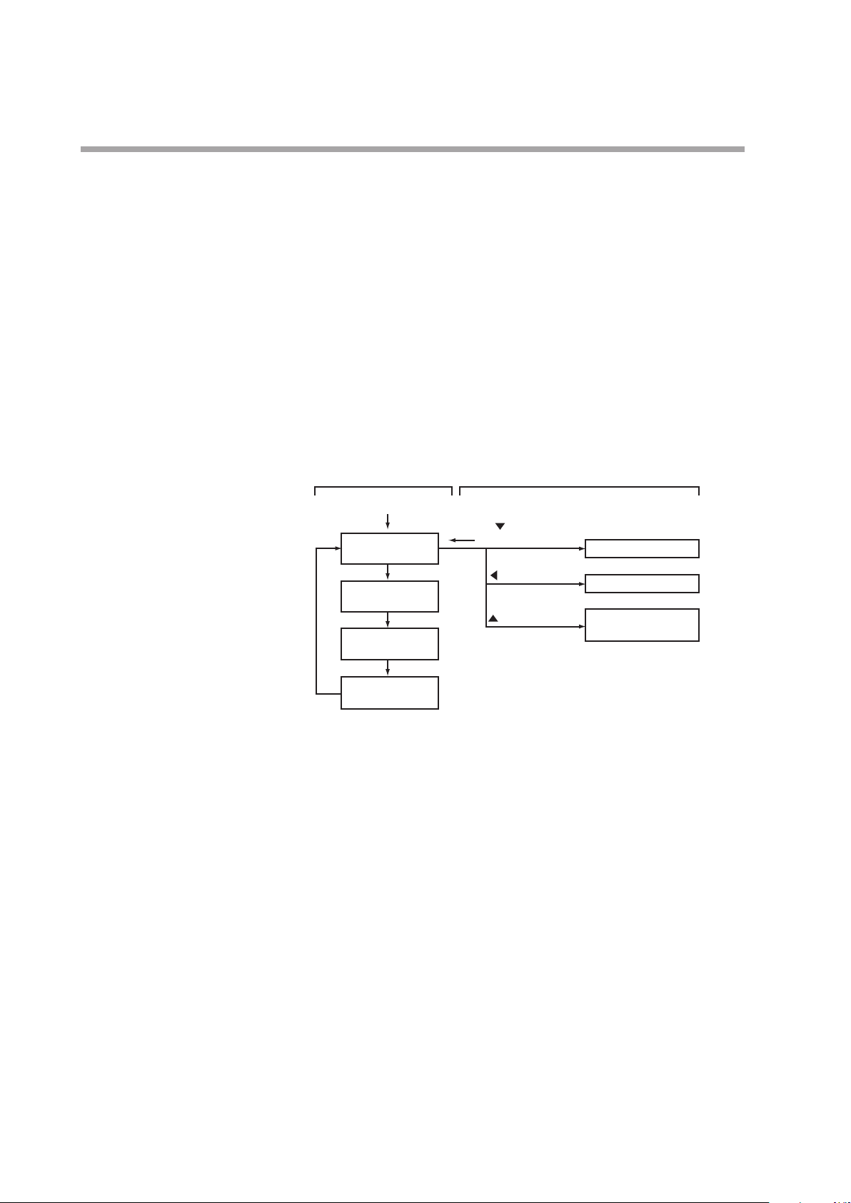
Basic operation Advanced operation
DISP key
Basic operation and advanced operation
This device provides two kinds of operations, basic operation and advanced
operation. Basic operation is the state of the device during normal use. In
basic operation, the contents of the 7-segment display can be changed to show
instantaneous flow rate, flow set value, totalized flow value, or amperage to the
valve in normal operation mode. Also, how to set the flow set value is described in
the basic operation part.
Advanced operation is for selecting various functions or setting parameters of the
device. When the device is used with the factory settings, no setup operation is
needed. However, to change the gas type, set a range, set an external contact input,
set upper and lower alarm limits, or set communication conditions (for models
with communication functions), it is necessary to configure various settings using
advanced operation. The diagram below gives an outline of operation flow. Basic
and advanced operation are described in Chapters 4 and 5, respectively.
Power ON
Instantaneous
ow rate display
DISP key
Flow set value
display
DISP key
Totalized ow
display
DISP key
Valve amperage
display
DISP key
key+ENT key
(3 s or more)
key (3 s or more)
key (3 s or more)
Function setup mode
Parameter setup mode
Controller information
display mode
1-10
Page 21
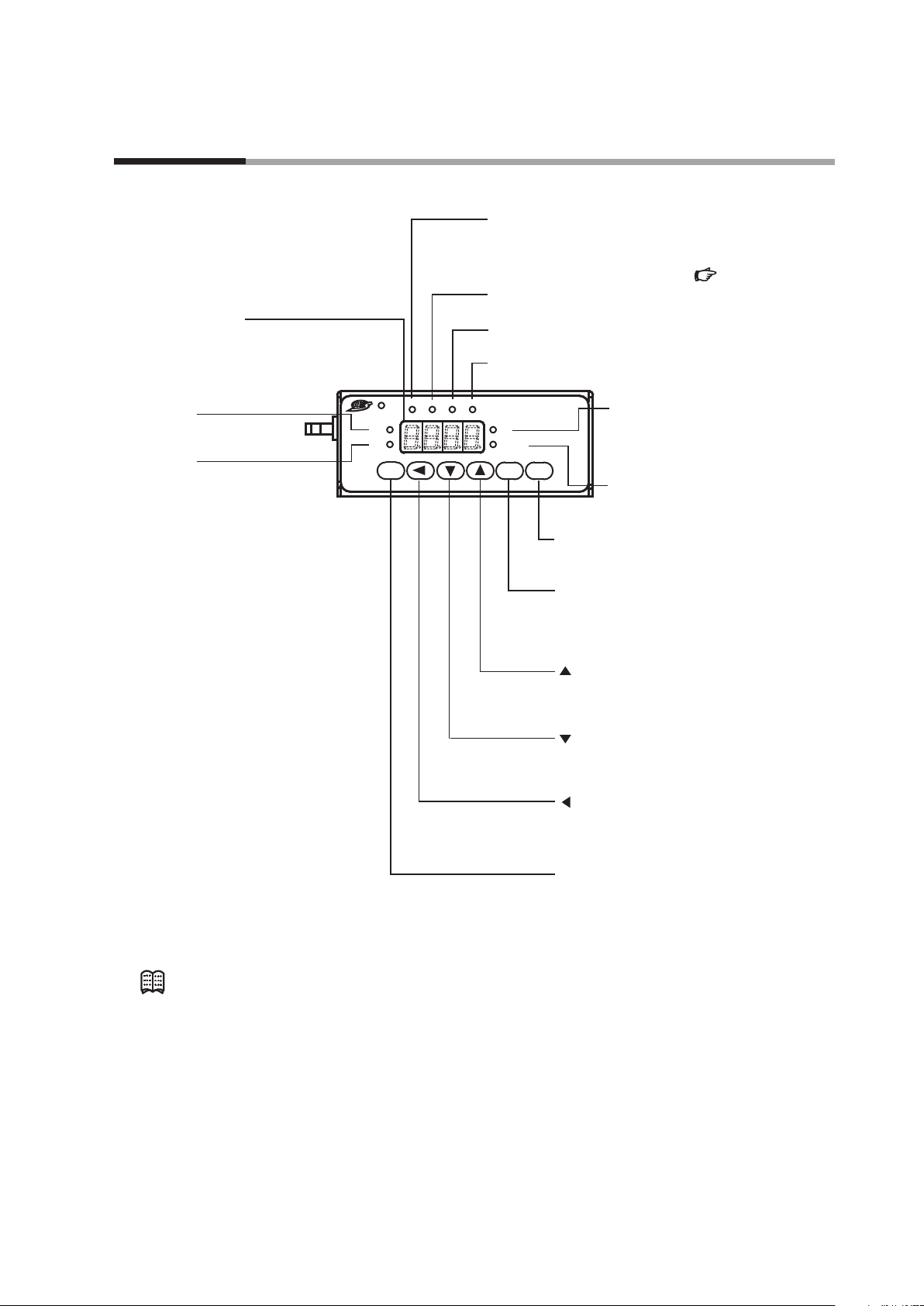
Chapter 2. NAMES AND FUNCTIONS OF PARTS
PV lamp:
OK lamp:
Use this key to change the operating mode.
reset alarm and move to the function setup mode.
Display
Lit when the deviation between the ow set value
and instantaneous ow rate is in the allowable range.
Set the allowable range in the parameter setup.
7-segment display:
Displays the instantaneous ow rate,
ow set value, totalized ow, amperage
to the valve and the operating mode.
It also displays parameter setup values, function
setup values and details of alarms.
SP lamp:
Lit when the ow rate
setpoint is displayed.
Lit when the instantaneous ow
rate is displayed.
ALM lamp:
Lit when an alarm occurs.
EV1 lamp
Lit when event 1 output is ON.
EV2 lamp:
Lit when event 2 output is ON.
OK ALM EV1 EV2
SP
PV
RUN ENT DISP
(For details on how to set parameters, )
:
L
L/min
Digital
Mass Flow
Controller
DISP key:
Use this key to switch the details displayed
on the 7-segment display.
ENT key:
Use this key to x and store the set value
to memory.
Also use it to reset the cumulative ow and to
L lamp
*1:
Lit when the totalized ow is
displayed.
Blinks when the cumulative
ow event occurs.
L/min lamp
Lit when the instantaneous ow rate
or ow set value is displayed.
P.5-11
*2:
Note
key:
Use this key to increment the setting value.
Additionally, this key is used to change to
the device information display mode.
key:
Use this key to decrement the setting value.
Also use it to move to the function setup mode.
key:
Use this key to move to a desired digit
when changing setting value. Also use it to
move to the parameter setup mode.
RUN key:
*1. This lamp is used for mL or m3 instead of L on some models.
*2. This lamp is used for mL/min instead of L/min on some models.
•
Technical terms used in this manual are defined as follows:
•
SP (setpoint): The flow set value (or flow rate setpoint)
•
PV (process variable): Instantaneous flow rate (or controlled flow rate)
•
Operating mode: 3 modes (valve fully closed/valve control/ valve fully
open)
2-1
Page 22
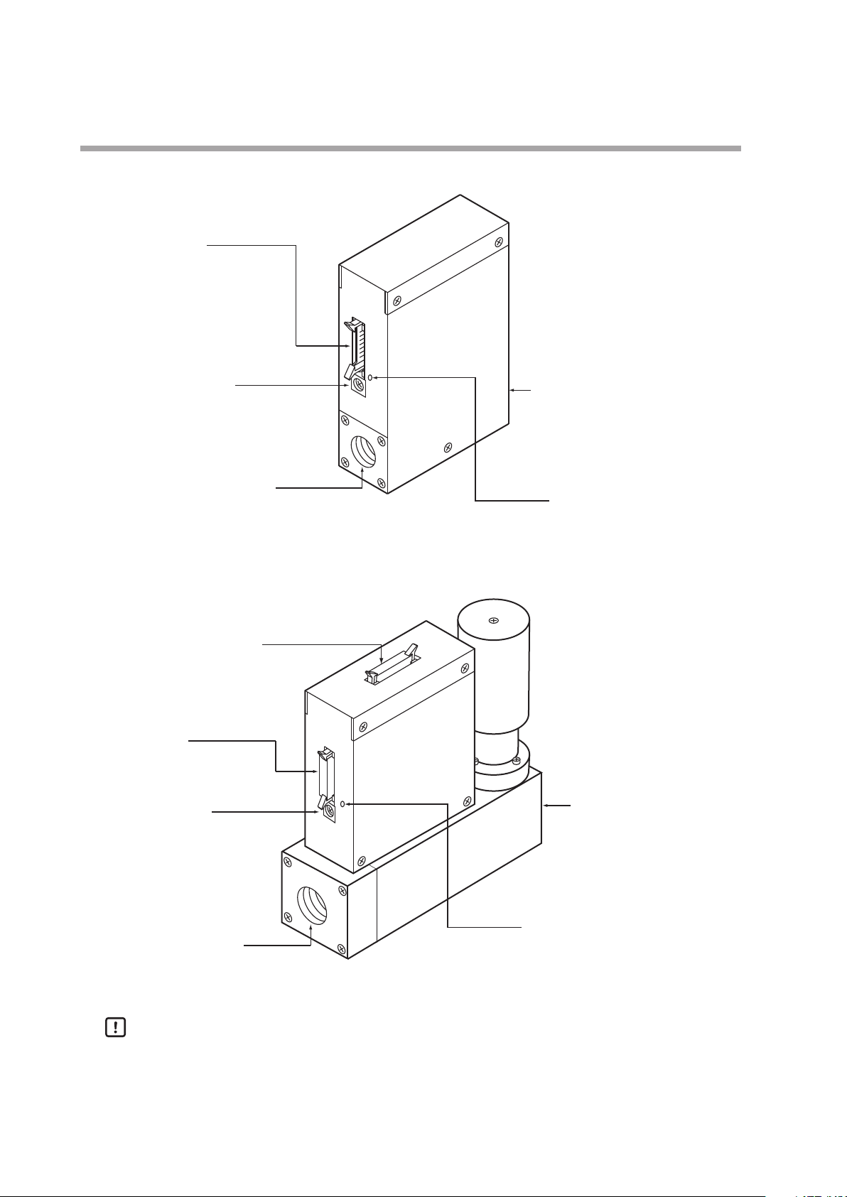
Chapter 2. NAMES AND FUNCTIONS OF PARTS
gas enters.
Jack for PC loader connection
Connector port:
This is used for I/O signals.
Use cable with dedicated
connector.
Jack for AC adapter:
Connect dedicated adapter here.
Model No.: 81446957-001
(24 V DC, 750 mA)
Pipe connection port (inlet):
This is the port through which
gas enters.
Pipe connection port (outlet):
Connector port:
This is used for I/O signals.
Use cable with dedicated
connector.
Connector for separate display:
This is used for connecting the
separate display unit.
Main unit (MQV9005/9020/9200/9500/0002/0005/0020/0050)
Jack for AC adapter:
Connect dedicated adapter here.
Model No.: 81446957-001
(24 V DC, 750 mA)
Pipe connection port (inlet):
This is the port through which
Main unit (MQV0050(J, K) /0200/0500)
Pipe connection port (outlet):
This is the port from which
gas is discharged.
2-2
Handling Precautions
This is the port from which
gas is discharged.
Jack for PC loader connection
•
The former AC adapter (model No. 81446682-001, 15 V DC/350 mA) can not be
used with MQV.
Page 23
Chapter 3. MOUNTING AND WIRING
Never allow gases that are within explosive limits to pass through this device. Doing so might
result in an explosion.
If the MQV is to be used for oxygen, make sure that it is a model designed for oxygen use. Even
if a device is designed for oxygen gas, do NOT use it for oxygen gas if it has been used for some
other gas even once. Oil contained in another gas may be deposited on the gas-contacting
parts and ignite upon reacting with oxygen.
Prevent foreign matter from entering the device. If rust, water droplet, oil mist, or dust in the
pipes enters the device, measurement or control error or damage might occur.
If there is a possibility of foreign matter entering the device, provide a filter, strainer or mist
trap capable of eliminating foreign matter 0.1 µm or greater in diameter at the upstream. Be
sure to inspect and replace the filter at regular intervals.
Use the device within the operating differential pressure range. Also, do not subject it to
pressure beyond the rated pressure resistance range. Doing so might damage it.
Do not subject this device to pressure above its pressure resistance. Doing so might damage it.
Be sure to use within the flow-rate range stipulated in the product specifications.
To prevent excessive flow, use a suitable means to control the supply pressure or use a throttle
valve or the like to control the flow rate.
If the flow rate exceeds the upper limit, both the flow rate display and the output voltage/
current may indicate considerably lower values than the actual flow rate.
If damage could result from the abnormal functioning of this device, include appropriate
redundancy in the system design.
The valve on this device cannot completely shut a flow off. If complete shutoff is required,
provide a shutoff valve separately. When the external valve is closed, it is necessary also to
fully close the valve of the device using either of the following methods:
If this valve remains in normal control status when the external shutoff valve is closed (zero
flow rate), there will be an excessively large flow as soon as the external shutoff valve is
opened. For the MQV0050(J, K), MQV0200(J, K), and MQV0500(J, K), if the external shutoff
valve is closed continuously for 5 minutes or more in control mode or with the valve forced
fully open, the valve overheating limit (AL71) will be activated and the current to the valve will
be forcibly limited.
WARNING
CAUTION
•
Set the flow rate setpoint to zero.
•
Make the valve operation mode to fully closed.
3-1
Page 24
Chapter 3. MOUNTING AND WIRING
Before connecting pipes with Swagelok or VCR connections, check the precautions in the
instruction provided by the connecting joint manufacturer.
When purchasing a connecting joint, use the following made by Swagelok Co., Ltd:
1/4" Swagelok: SS-400-1-6ST (standard)
1/2" Swagelok: SS-810-1-8ST (standard)
1/4" VCR: SS-4-VCR-1-00032SC11
1/2" VCR: SS-8-VCR-1-8STSC 11 or equivalent
When controlling oxygen flow, use an oxygen model and observe the following:
The device is a precision instrument. Do not drop it or subject it to impact, or it might be
damaged.
SS-400-1-6STSC11 (oil-inhibited)
SS-810-1-8STSC11 (oil-inhibited)
•
Piping should be carried out by a specialist skilled in handling oxygen gas.
•
Use oil-free pipes and parts.
•
Be sure to remove foreign matter, burrs, etc. from the pipes before connecting the device.
CAUTION
Mounting
Installation locations
z
Avoid mounting the device in the following locations:
•
Locations subject to high and low temperature and humidity
•
Locations whose atmospheres contain large amounts of dirt and dust, salt, conductive
substances such as iron powder, water droplet, oil mist or organic solvents
•
Locations subject to direct sunlight and rain
•
Locations directly subject to mechanical vibration or shock
•
Locations close to sources of electrical noise
•
Locations where strong magnetic or electrical fields are generated
Handling Precautions
•
The valve of this device cannot completely shut a flow off. If complete
shutoff is required, provide a shutoff valve separately.
Changing the display direction (models with integrated display only)
z
The display can be turned 180˚, in case the controller has been mounted with the
display upside-down.
3-2
Page 25

Chapter 3. MOUNTING AND WIRING
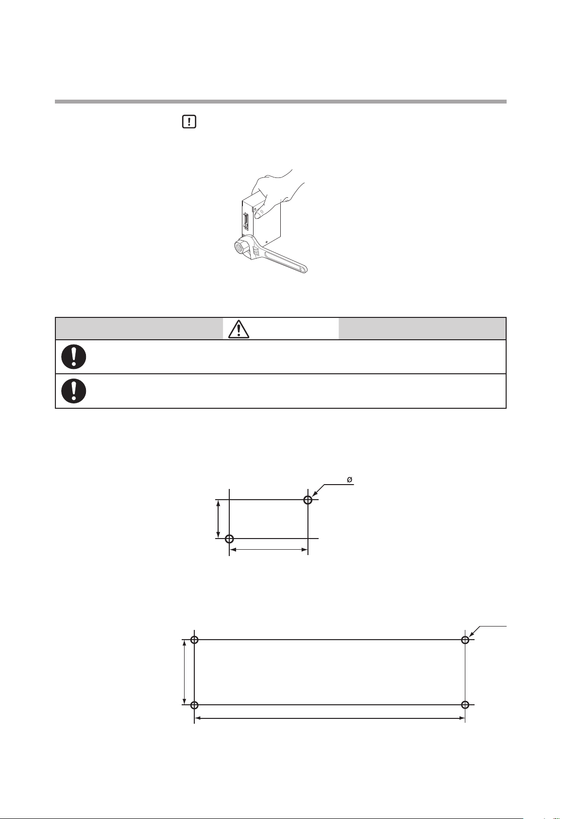
When installing joints (UNF connections), secure the lower part of the main unit in a vise or the
like gripped between rags to protect the finished surfaces, and turn the joint to tighten. The
device may be damaged if the lower main unit is not secured.
Connector latches
Main unit
•
Procedure
(1) Turn the power OFF.
(2) Remove the four screws holding the display.
(3) Lift up the display from the main unit, and turn it 180˚ counterclockwise.
(4) Put the display back on the main unit, and fasten with the four screws
(5) To return the display to its original position on the body, turn it 180˚
Handling Precautions
•
Before changing the display direction, be sure to turn the power OFF.
•
Prevent foreign objects from falling inside the main unit when the display
is taken off. Failure to do so might cause trouble or malfunction.
•
Do not remove the connectors used inside the main unit.
Installing joints (UNF) connections
z
taken off in step (2).
clockwise.
CAUTION
Rag
3-3
Page 26
Chapter 3. MOUNTING AND WIRING
Incorrect
Mount securely in order to prevent vibration. Otherwise, equipment failure could result.
Mount the device horizontally. Do not mount it with the display facing down. Doing so might
cause measurement error or equipment failure.
15
4.5
27
4.5 ø
Installation procedure
z
Handling Precautions
•
Do not hold the top part of the main unit with your hand. Doing so might
deform the case.
•
Take special care not to damage the connector latches.
CAUTION
z MQV9200/9500/0002/0005/0020/0050
Install the device with two M4 screws using the mounting holes on the base of the
device.
z MQV0050(J, K)/0200/0500
Install the device with four M4 screws using the mounting holes on the base of the
device.
unit: mm
30
unit: mm
110
3-4
Page 27
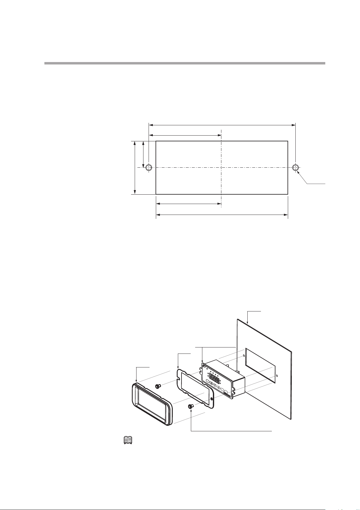
Installing the separate display unit
35 ±0.2
Panel cutout dimensions
(cross recessed head machine screws)
Panel
z
For models with a separate display
(1) Make mounting holes in the panel according to the panel cutout dimensions.
17.5 ±0.2
Chapter 3. MOUNTING AND WIRING
unit: mm
100 ±0.2
50 ±0.2
M4 (2)
45 ±0.2
(2) Mount the display and secure it by tightening the screws.
Installing the front cover for the separate display unit
z
For models with a separate display, a front cover (decorative frame) can be
mounted. Use of this cover makes it possible to hide the mounting screws,
improving the appearance.
Items needed for installation
• Front cover (81446858-001), 1 set
• Phillips screwdriver
Plate
Mask
90 ±0.2
Separate display
unit
Procedure
(1) As shown in the figure, put the plate over the display panel, and then secure it
(2) Fit the mask onto the display to mount it.
Mounting screws
Note
•
The front cover set includes one mask, one plate, and two mounting screws.
to the display by tightening the screws.
3-5
Page 28
Chapter 3. MOUNTING AND WIRING
Mount this device horizontally. However, do not mount with the display facing down. Doing so
might cause measurement error or device failure.
For the MQV0050(J, K)/0200(J, K)/0500(J, K), use the largest pipe possible in order to reduce
pressure loss in the pipes, and do not install any equipment near the device that can cause
a large pressure loss. If there is a large pressure loss in the pipes or equipment, the pressure
of the gas supply to this device (operation differential pressure) will be affected and will
fluctuate greatly with the flow rate. This could result in unstable control.
When making the pipe connections, hold the hexagonal part of the connector section and turn
the pipe to tighten. After connecting, check that there are no gas leaks.
If using Rc connections, take care not to coat with too much sealant. Foreign matter or burrs in
the pipes may also cause measurement errors.
Correct
Incorrect
Sealant
Piping
CAUTION
Handling Precautions
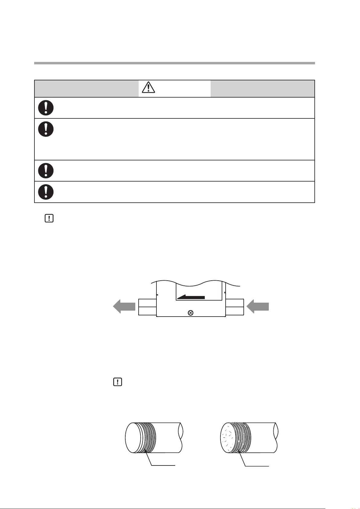
•
Make sure that the gas flows into the device in the direction indicated by the
FLOW arrow on the main unit. Otherwise, the flow rate cannot be controlled
correctly.
•
Do not touch the pipe sections of a controller treated to be oil-free with your
bare hands. Doing so will degrade the oil-free treatment.
•
Do not hold the top part of the main unit with your hand when connecting
piping. Doing so might deform the case.
Fasten and connect pipes to the body using a wrench (spanner) or similar tool on
the hexagonal sections of the joints.
Coating sealant (Rc connection)
z
Handling Precautions
•
FLOW
GasGas
Coat with an appropriate amount of sealant. Do not coat the top two
threads. Remove any dirt or burrs from inside the pipes.
3-6
Sealant
Page 29
Wiring
Do not apply a negative voltage or a voltage exceeding 5 V to the external setup voltage input
terminal. Doing so might cause malfunction or equipment failure.
When using a relay for external contact input and/or external 3-way switching input, always
use a relay designed for micro-current use (with gold contacts). Failure to do so could cause
faulty contact, resulting in malfunction.
If there is a risk of a power surge caused by lightning, use a surge protector to prevent fire or
equipment failure.
Gas type switching by external contact input, flow rate switching, and analog input/output
voltage range switching by external 3-way input switching should be done only after setting
the operation mode to fully closed. Switching while controlling could cause large fluctuations.
Be sure to check that the wiring is correct before turning the power on. Incorrect wiring could
cause damage or malfunction.
View from connector insertion side
Chapter 3. MOUNTING AND WIRING
CAUTION
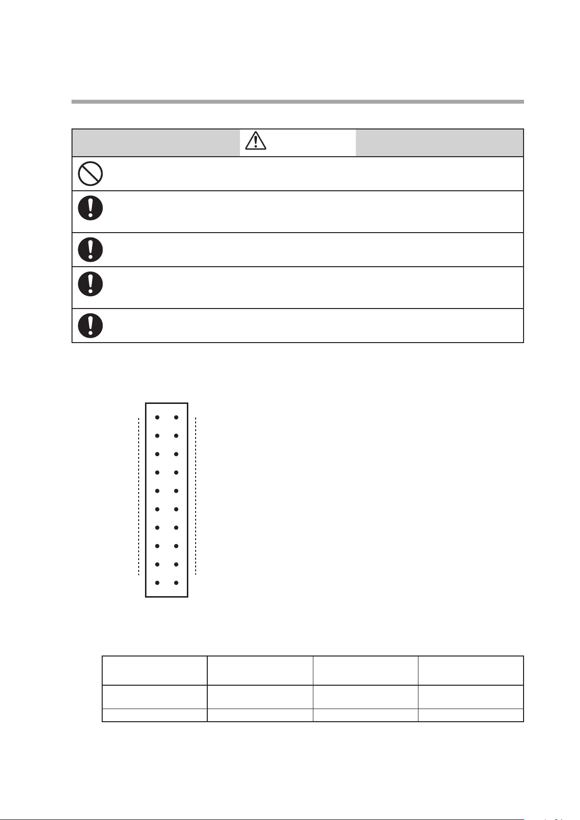
Connector pin layout
z
Connector model No. (device side): HIF3BA-20PA-2.54DS
20 19
2
Table of compatible connectors (all made by HIROSE ELECTRIC CO., LTD.)
z
1
Manufacturer: HIROSE ELECTRIC CO., LTD.
Connector type
Contact crimp type HIF3BA-20D-2.54C HIF3-2226SCC AWG#22 to #26
Cable clamp type HIF3BA-20D-2.54R Not required AWG#28 (flat cable only)
Compatible connector
model No.
Compatible contact
model No.
Compatible wire
(single wire allowed)
3-7
Page 30

Chapter 3. MOUNTING AND WIRING
4
24 V DC
POWER GND
POWER (24 V)
POWER (24 V)
or 9 D.GND
DB
8
6
DB
DA
SG
Connector signal names
z
Pin number Signal name Description Remarks
20 +5 V (5 mA max.) 5 V DC reference voltage outputa 5 mA max.
19 FLOW OUT Instantaneous flow rate (PV) or
18 A.GND Analog ground Analog signal common
17 FLOW SP INPUT Setpoint flow rate (SP) voltage
16 MODE INPUT External 3-way switching input 3-stage switching input
15 DI3 External contact input 3 2-stage switching input
14 DI2 External contact input 2
13 DI1 External contact input 1
12 EV2 OUT Event output 2 Open collector non-insulated output
11 EV1 OUT Event output 1
10 ALM OUT Alarm output
9 D.GND Digital ground Digital signal common
8 DB RS-485 communications DB Do not connect on models without the
7 DA RS-485 communications DA
6 D.GND Digital ground Digital signal common
5 TEST For test Do not use.
4 POWER GND Power supply ground Connect two wires each in parallel to the
3 POWER GND Power supply ground
2 POWER (24 V) Power supply + (24 V DC)
1 POWER (24 V) Power supply + (24 V DC)
flow rate setpoint (SP) output
input
0 to 5 V/1 to 5 V/0 to 20 mA/ 4 to 20 mA
output
0 to 5 V/1 to 5 V/0 to 20 mA/ 4 to 20 mA
input
(OPEN/GND/5 V)
(OPEN/GND)
communications function.
power supply to reduce voltage drop
caused by wiring resistance.
Wiring
z
• Power supply
POWER GND
3
+-
2
1
• RS-485 communications (for models with optional RS-485 only)
7
DA
Note
•
For details on wiring for RS-485 communication, Digital Mass Flow
Controller User's Manual: Communications, CP-SP-1197E.
3-8
Page 31

• Alarm output/event output
12
Load
EV2 OUT
or 6 D.GND
15
9
DI3
or 6 D.GND
19
0 to 5 V/1 to 5 V
0 to 20 mA/4 to 20 mA
0 to 5 V/1 to 5 V
0 to 20 mA/4 to 20 mA
FLOW OUT
FLOW SP INPUT
20
+5 V
FLOW SP INPUT
Chapter 3. MOUNTING AND WIRING
Load
Load
+ -
11
EV1 OUT
10
ALM OUT
9
Handling Precautions
•
Take special care that the event and alarm outputs do not exceed the
output rating of the device. Additionally, when driving a relay, use an
appropriate coil surge absorption diode built-in relay. Failure to do so
might cause the device to malfunction.
• External contact input
DI2
14
13
DI1
Handling Precautions
•
When switching by relay contact, use an appropriate relay intended for
micro-current use (with gold contacts). Failure to do so could cause faulty
contact, resulting in malfunction.
• Analog I/O
+
Output
—
+
Input
—
• When using potentiometer (0 to 5 V)
18
A.GND (0 V)
17
18
17
A.GND
3-9
Page 32

Chapter 3. MOUNTING AND WIRING
20
OPEN
+5 V
MODE INPUT
• External 3-way switching input
0 V
Operation of external 3-way switching input
18
5 V
A.GND (0 V)
16
Handling Precautions
•
When switching by relay, use an appropriate relay intended for microcurrent use (with gold contacts). Failure to do so could cause faulty
contact, resulting in malfunction.
Input state of pin No.16
Assigned function
Switching of operating mode 1 Control Fully closed Fully open
Switching of operating mode 2 Fully closed Control Fully open
Switching of SP No. SP-0 SP-1 SP-2
Switching of totalizing operation Continue
Switching of analog I/O
voltage range
* "Internal reference" refers to the use of the 5 V DC reference voltage pin (No. 20) on
this device, and is used when the setting value is set by an externally connected
potentiometer.
Input Internal
Output
OPEN GND 5V
Reset Stop counting
counting
External
reference
0 to 5 V or
0 to 20 mA
0 to 5 V/0 to
20 mA
reference
0 to 5 V or
external
reference
0 to 20 mA
0 to 5 V/0 to
20 mA
*
External
reference
1 to 5 V or
4 to 20 mA
1 to 5 V/4 to
20 mA
Note
•
For details on how to assign external 3-way switching input functions,
Chapter 5, ADVANCED OPERATION Function setup items
C-09
(P.5-4).
3-10
Page 33

Example of wiring
Input/output circuit
Instantaneous owrate output
z
Chapter 3. MOUNTING AND WIRING
Potentiometer
(5 kΩ)
Event output 2
Event output 1
Alarm output
(Output common)
0 V
+
-
OPEN
+5 V
DB
DA
SG
+5 V (5 mA max.)
FLOW OUT
A.GND
FLOW SP INPUT
MODE INPUT
DI3
DI2
DI1
EV2 OUT
OUT
EV1
ALM OUT
D.GND
DB
DA
D. GND
TEST
Internal circuit
20
19
18
17
16
15
14
13
12
11
10
9
8
7
6
5
Handling Precautions
•
Do not input any signal to pin No. 5.
•
The power circuit is isolated from the input/output circuit inside this device.
•
Even though the analog GND and digital GND are connected internally, always
carry out the grounding wiring individually.
•
When the AC adapter plug is inserted into the AC adapter power supply
terminal, the power supply changes from the DC power supply to the AC
adapter.
•
The former AC adapter 81446682-001 (15 V DC, 350 mA) cannot be used with
this device.
+
-
Power supply
(24 V DC)
POWER GND
POWER GND
POWER (24 V)
POWER (24 V)
AC adapter input
4
3
2
1
Power circuit
+
-
3-11
Page 34

Chapter 3. MOUNTING AND WIRING
20
Connector terminal block
z
Sometimes two or more connections must be made to the same pin during wiring.
In this case, use a connector terminal block. If you need a 20-core cable for the
connectors on the device and connector terminal block, contact the azbil Group or
your dealer.
Note
•
Recommended connector terminal block
Manufacturer: Toyo Giken
Model: PCN-1H-20
M ounting connector
HIROSE ELECTRIC CO., LTD., HIF3BA-20PA-2.54DSA
Compatible connector (other side)
HIROSE ELECTRIC CO., LTD., HIF3BA-20D-2.54R
This terminal block can be mounted directly on a DIN rail.
The following table shows the correspondence between connector pin Nos. and
terminal block Nos:
Handling Precautions
•
For details regarding the cable with connector on both ends, contact
the azbil Group. (The optional dedicated connector, 81446681-001 or
81446951-001, cannot be used to connect to the connector terminal
block.)
•
The specifications of the recommended connector terminal block are
subject to change. Contact the manufacturer beforehand for details.
Pin No. Terminal block No.
20 B-10
19 A-10
18 B-9
17 A-9
16 B-8
15 A-8
14 B-7
13 A-7
12 B-6
11 A-6
10 B-5
9 A-5
8 B-4
7 A-4
6 B-3
5 A-3
4 B-2
3 A-2
2 B-1
1 A-1
2
19
Cable with connector
on both ends
Connector terminal
block
1
MQV
3-12
Page 35

Chapter 4. BASIC OPERATION
Do not operate the console keys using a sharp object such as a mechanical pencil or
screwdriver. Doing so might damage the console.
Power ON
go out)
4 - 1 Switching Displays
CAUTION
Basic operation
Basic operation is used to change the display to instantaneous flow rate (PV), flow
set value (SP), totalized flow value, or valve amperage.
Normally, when the power is turned ON, the instantaneous flow rate is displayed
in basic operation mode. When this is the case, operating the DISP key changes the
contents of the 7-segment display as described below.
Instantaneous ow rate display (PV and L/min lamps lit)
DISP key
Flow set value display (SP and L/min lamps lit)
DISP key
Totalized ow display (L lamp lit)
DISP key
Valve amperage display (SP, PV, L, and L/min lamps
DISP key
Handling Precautions
•
If there is no operator input for approximately 10 seconds while the flow set
value is being displayed, the display automatically reverts to the instantaneous
flow rate display.
•
On the MQV9005/9020/9200, the mL/min lamp replaces the L/min lamp.
On the MQV9005/9020, the mL lamp replaces the L lamp, and on the
MQV0050(J, K)/0200/0500, the m3 lamp replaces the L lamp.
Indicating instantaneous flow rate (PV display)
z
When the power is turned ON, the PV and L/min lamps light, and the
instantaneous flow rate is indicated on the display.
Handling Precautions
•
When the operating mode is set to fully closed, and the flow rate is zero,
and when the operating mode is switched to the control mode or fully
open mode, the operating mode (
one second.
•
When an alarm occurs, the alarm code and the PV are displayed
alternately.
OFF/ON/FULL
) is displayed for about
4-1
Page 36

Chapter 4. BASIC OPERATION
Indicating the flow set value (SP display)
z
If DISP key is pressed while the instantaneous flow rate is displayed, the PV lamp
goes out, the SP lamp lights and the flow set value (SP) is indicated on the display.
Handling Precautions
•
If the SP value is not changed for about 10 seconds while the flow
set value is displayed, the instantaneous flow rate is redisplayed
automatically. For details on how to change the flow rate, 4 - 2 S etting
the Flow Rate (P.4-4).
•
When multiple setpoints (2 to 8 SPs) have been selected in
function setup, when switching by external input, the flow set value (SP
value) is displayed for about one second, and then the display switches to
the SP No.
c-04
in the
Indicating the totalized flow
z
When the DISP key is pressed while the flow set value (SP) is displayed, the SP and
L/min lamps go out, the L lamp lights up, and the totalized flow value is indicated
on the display.
When the totalized flow value is 10,000 or higher, the number is displayed in two
parts, the last four digits, followed by the first four digits. When the value is the last
four digits, the decimal point on the display is lit up.
For example, when the totalized flow value is "123,456L", "3 4 5 6." is displayed.
Press the DISP key to display " 1 2". To alternately display the first and last four
digits, press the
Handling Precautions
•
When an alarm occurs, the alarm code and the totalized flow value are
displayed alternately.
Resetting the totalized flow count
z
The totalized flow value is reset to zero by holding down the ENT key for two
seconds or more while the totalized flow value is displayed.
Note (Advanced operation)
•
Totalized flow event output function
When "1: Totalized flow rate count up ON" is selected as the event output
type for function setup
totalized flow value reaches the totalized flow event setting. This threshold
value for the totalized flow event is set in the parameter setup mode.
key.
C-07
or
, the event output turns ON when the
C-08
4-2
•
Totalized flow event automatic valve shut-off function
When "1: Function enabled" is set for the automatic valve shut-off function
in function setup C-13, the valve will be automatically closed fully if the
totalized flow value reaches the preset value.
The threshold value for the totalized flow event is set in the parameter setup
mode.
For details on function setup and parameter setup, Chapter 5.
ADVANCED OPERATION.
Page 37

Valve amperage display
z
Chapter 4. BASIC OPERATION
If DISP key is pressed while the totalized flow is displayed, the PV, SP, L and L/
min lamps go out, and the electrical current to the valve (
indicated on the 7-segment display.
Note (Advanced operation)
•
When "1: Only upper limit alarm used," "2: Only lower limit alarm used,"
or "3: Upper and lower limit alarm used" is selected for valve amperage
alarm type (
activated if the valve current exceeds the upper limit set value or goes below
the lower limit value. The valve amperage upper and lower limits are set in
the parameter setup mode.
For details on function setup and parameter setup, Chapter 5.
ADVANCED OPERATION.
in the function setup), the valve amperage alarm will be
C-20
0.0
to 1
00.0
[ %]) is
Handling Precautions
•
The valve amperage can vary greatly according to the differential
pressure even at the same flow rate. The valve amperage alarm function
cannot be used unless the differential pressure is stable.
•
Even under stable differential pressure conditions, the relationship
between the valve amperage and flow rate has hysteresis characteristics
(amperage may vary even at the same flow rate).
When using the valve amperage alarm, be sure to test sufficiently under
operating conditions. That way, an appropriate alarm current setting can
be determined.
4-3
Page 38

Chapter 4. BASIC OPERATION
*
Factory setting
4 - 2 Setting the Flow Rate
Set the ow rate as shown below.
Digital setup
Flow set value Selection from function setup C-03
Analog setup
*
Selection from function setup C-04
Multi-setup
Voltage setup
Selection from function setup C-05 and C-06
Current setup
Two kinds of setup methods, that is, digital and analog setup, are provided to set
the flow rate. Additionally, the digital setup further provides two kinds of setup
methods, single setup and multi-setup.
In single setup, the flow rate is set through key input or communications. In multisetup, the flow rate is set through the key input, communications, external contact
input, or external 3-way switching input. One flow set value can be set in the single
setup while up to eight flow set values can be set in the multi-setup.
*
Key input or communicationsSingle setup
Key input or communications
External contact inputs
External 3-way switching input
Internal reference 0 to 5 V input
External reference 0 to 5 V/1 to 5 V input
External reference
0 to 20 mA/4 to 20 mA input
In the analog setup, the flow rate is set through the external voltage/current input.
The factory setting is digital setup.
Either digital setup or analog setup is selected as the flow rate setup method (
in the function setup).
0: Digital setup (flow rate is set through the key input or communication.)
1: Analog setup (flow rate is set through the external analog voltage/current.)
For further detailed setup, make selections in
For details on function setup,
Handling Precautions
•
Setup by communications is available only for models with RS-485
communications.
C-04
to
in the function setup.
C-06
Chapter 5. ADVANCED OPERATION.
C-03
4-4
Page 39

Digital flow rate setup
Chapter 4. BASIC OPERATION
Up to eight SP values can be set on this device. The operating procedure may vary
depending on the number of SP values to be set.
Single setup (number of SPs in function setup
z
Follow the procedure below to change the SP value:
(1) Press the DISP key.
>> The SP (flow rate setpoint) is shown on the 7-segment display
(2) Change the SP value by pressing the
be changed by pressing the key.
>> The digit currently being changed starts blinking.
(3) When you have reached the target value, press the ENT key.
>> The SP value is set, and saved.
Note (Advanced use, direct setup function)
•
Control can be executed using an SP value currently being changed
(indicated by blinking display) when the direct setup function is enabled
for the instantaneous flow rate direct setup function ON/OFF (
function setup). In this case, the ENT key need not be pressed to enter the SP
value.
Handling Precautions
•
When switching the display by pressing the DISP key, first press the ENT
key to enter the SP value, and switch the display.
For details on how to set up functions, Chapter 5. ADVANCED
OPERATION.
C-04
is 1)
or keys. You can move to the digit to
in the
C-2 1
Multi-setup (number of SPs in function setup
z
In multi-setup, up to eight SP values can be switched by key operation and by
external contact input.
Follow the procedure below to change the SP No. and SP value:
(1) Press the DISP key.
>> The display switches to SP No.
(2) Press the
>> The SP No. is entered.
(3) Change the SP value by pressing the
be changed by pressing the key.
>> The digit currently being changed blinks while the SP value is being changed.
(4) When you have reached the target value, press the ENT key to enter the new SP
value.
>> The SP value and SP No. are updated, and the SP value of the selected SP No. is
new the active SP.
or keys to change the SP No. and press the ENT key.
C-04
is 2 to 8)
SP-0
to
after about one second.
SP-7
or keys. You can move to the digit to
4-5
Page 40

Chapter 4. BASIC OPERATION
Note (Advanced use, direct setup function)
•
Control can be executed using an SP No. or SP value currently being
changed (indicated by blinking display) when the direct setup function
is enabled for the instantaneous flow rate direct setup function ON/OFF
(
in the function setup). In this case, the ENT key need not be pressed
C-21
to enter the SP value.
Handling Precautions
•
When switching the display by pressing the DISP key, first press the ENT
key to enter the SP value.
For details on how to set up functions, Chapter 5. ADVANCED
OPERATION.
Handling Precautions (Common to single setup and multi-setup)
•
When "1: Analog setup" is selected as the flow rate setup method (
in the function setup) and the SP value is controlled by external voltage
input, the SP value and SP No. cannot be changed with the or key.
C-03
•
If no operation is made for approximately 10 s after the operation stated
in (1) has been performed, the display automatically returns to the
instantaneous flow rate display.
•
If the DISP key is pressed during the operations in steps (2) and (3)
(setting is blinking), the SP No. and SP value return to their previous
values without saving of new values.
•
When the SP value is updated in step (3) for single setup or in step (4) for
multi-setup, the display automatically returns to the instantaneous flow
rate display after approximately 2 s have elapsed.
4-6
Page 41

Flow rate setup by external contact input (Advanced use)
When assigning "3: Switching of SP No." at external contact input function
assignment C- 1 0 to C- 1 2 in the function setup, up to eight SP values can be
changed by means of external contact ON and OFF combinations.
Chapter 4. BASIC OPERATION
(1) When the number of preset SP values is set to 5 to 8 in function setup
Assign "3: Switching of SP No." to all of C- 10 to C- 12 in the function setup.
Input 3 (DI3) Input 2(DI2) Input 1(DI1) Selected SP
External contact
input state
(2) When the number of SP values is set to 3 or 4 in function setup
OFF OFF OFF SP-0
OFF OFF ON SP-1
OFF ON OFF SP-2
OFF ON ON SP-3
ON OFF OFF SP-4
ON OFF ON SP-5
ON ON OFF SP-6
ON ON ON SP-7
C-04
Assign "3: Switching of SP No." to two of C- 10 to C- 12 in the function setup.
External contact input pair
External contact
input state
Input 2 (DI2) Input 1 (DI1)
Input 3 (DI3) Input 1 (DI1)
Input 3 (DI3) Input 2 (DI2)
OFF OFF SP-0
OFF ON SP-1
ON OFF SP-2
ON ON SP-3
Selected SP
C-04
.
.
(3) When the number of SP values is set to 2 in function setup
External contact
input state
Handling Precautions
•
When changing the SP number by external contact input, the and keys
cannot be used (but the SP value can be changed).
.
C-04
Assign "3: Switching of SP No." to one of C- 10 to C- 12 in the function setup.
Input 1 to 3 (DI1 to DI3) Selected SP
OFF SP-0
ON SP-1
4-7
Page 42

Chapter 4. BASIC OPERATION
Flow rate setup by external 3-way switching input (Advanced use)
When "2: Switching of SP No." is assigned at external 3-way switching function
in the function setup, three SP values (
C-09
the external 3-way switching input as described in the table below.
External 3-way switching input state Selected SP
OPEN SP-0
0 V SP-1
5 V SP-2
SP-0
Handling Precautions
•
When the SP No. is switched by the external 3-way switching input, you
cannot switch the SP No. using or keys, though you can switch the SP
value.
to
) can be changed with
SP-2
4-8
Page 43

Analog flow rate setup
Chapter 4. BASIC OPERATION
The SP value (flow set value) can be changed by analog voltage by selecting analog
setting as the flow rate setting method in function setup
. For details on how
C-03
to set up the function, Chapter 5. ADVANCED OPERATION.
The setup voltage/current range can be selected in the input range selection for
analog setup (
in the function setup).
C-05
The selection of voltage input/current input is linked automatically with the settings
for analog output type and range selection (
in the function setup). For
C-06
example, when current output is selected as analog output type and range selection
in
, the input type becomes current input type. Then, analog setup voltage/
C-06
current for SP value can be calculated by the equations below.
Function setup
C-05
0 Internal reference 0 to 5 V
1 External reference 0 to 5 V/
2 External reference 1 to 5 V/
* Internal reference 0 to 5 V input means that the 5 V-reference voltage input of connector pin No. 20 of this controller
is used and a voltage is input with the optional potentiometer (variable resistor with dial).
In this case, no external power supply for setup is needed. The reference voltage (5 V) is not accurate, so to actually
measure and calculate the reference voltage output from this controller, use a voltage tester for the setup voltage
calculation.
Input voltage/current range Setup voltage/current equation
*
/
Setup voltage [V] = Setting flow rate ÷ Full-scale flow rate x
External reference 0 to 20 mA
External reference 0 to 20 mA
External reference 4 to 20 mA
Reference output voltage
Setup current [mA] = Setting flow rate ÷ Full-scale flow rate x 20
Setup voltage [V] = Setting flow rate ÷ Full-scale flow rate x 5
Setup current [mA] = Setting flow rate ÷ Full-scale flow rate x 20
Setup voltage [V] = Setting flow rate ÷ Full-scale flow rate x 4 + 1
Setup current [mA] = Setting flow rate ÷ Full-scale flow rate x 16 + 4
Note (Advanced use)
•
When "1: Function enabled" is selected for analog optional scaling function
in the function setup, the full scale flow rate can be changed to a
C-28
desired level during analog setup. In this case, the full-scale flow rate of the
analog flow rate output voltage/current (PV output voltage/current) is also
changed as it is linked with the above flow rate. The scaling flow rate is set in
the parameter setup mode.
For details on how to set up functions, Chapter 5. ADVANCED
OPERATION.
4-9
Page 44

Chapter 4. BASIC OPERATION
(2 s or more)
(less than 2 s)
(less than 2 s)
4 - 3 Selecting the Operating Mode
Operating mode selection
Three kinds of valve operating modes are provided, "control mode," "fully closed
mode," and "fully open mode."
The factory setting is the control mode. The operating mode can be forcibly
changed to "fully closed mode" (valve is fully closed) or "fully open mode" (valve is
fully open).
As shown in the diagram below, the mode is changed alternately between the
control mode and fully closed mode every time the RUN key is pressed.
Additionally, to change the mode from the control mode to the fully open mode,
keep the RUN key pressed for 2 seconds or longer.
Control mode
Operating mode display
Operation mode 7-segment display OK lamp Remarks
Fully closed mode
Control mode
Fully open mode
RUN key
Fully closed mode
RUN key
Fully open mode
RUN key (less than 2 s)
RUN key
RUN key (2 s or more)
The operating mode is shown on the 7-segment display during instantaneous flow
rate display. Additionally, the OK lamp blinks in the fully open mode.
Out
Out or lit
Full
Note (Advanced use, Selecting the operating mode through external input)
•
When "operating mode change (5, 6, or 8)" is selected for external contact
Blinking
is always displayed after checking that the flow
OFF
rate is zero (0).
is displayed for approximately 1 second when
On
the mode changes to the control mode.
is displayed for approximately 1 second when
Full
the mode transits to the fully open mode.
input function assignment C- 10 to C- 12 in the function setup, the
operating mode can be changed through external contact input.
4-10
•
When "operating mode change (1, or 5)" is selected for external 3-way
switching input function assignment
in the function setup, the
C-09
operating mode can be changed through the external 3-way switching input.
For details on how to set up functions, Chapter 5. ADVANCED
OPERATION.
Page 45

Handling Precautions
•
When "0: RUN key disabled" is selected for "
operating mode selection when power turned ON" in the function setup, the
operating mode is not changed even though the RUN key is pressed.
•
When "operating mode change (5, 6, or 8)" is selected for external contact
input function assignment C- 10 to C- 12 in the function setup, changes
by external contact take precedence over RUN key operation. In the same
manner, when "operating mode change (1 or 5)" is selected for external 3-way
switching function
input takes precedence over the RUN key operation.
•
The fully open mode cannot directly be changed to the control mode. To make
the change, press the RUN key to change the fully open mode to the fully
closed mode. After that, press the RUN key again to change the fully closed
mode to the control mode.
Chapter 4. BASIC OPERATION
: RUN key operation and
C-02
in the function setup, the external 3-way switching
C-09
4-11
Page 46

Page 47

Valve amperage display
Basic operation Advanced operation
DISP key
Chapter 5. ADVANCED OPERATION
The advanced operation provides three kinds of modes, "Function setup mode," "Parameter setup mode," and
"Controller information display mode."
Setup mode transition operation
Normally, when the power is turned ON, the instantaneous flow rate is displayed in
the basic operation mode.
When keys are operated as described in the diagram below during instantaneous
flow rate display, the operation changes to the specified mode.
When the operating mode changes to "Function setup mode" or "Parameter setup
mode," the specified setup can be changed.
In the "Device information display mode," you can check the statuses of major setup
items (gas type, full scale flow rate, reference temperature, and communications
address).
Power ON
DISP key
Instantaneous ow rate display
DISP key
Flow set value display
DISP key
Totalized ow display
DISP key
key + ENT key
(3 s or more)
key (3 s or more)
key (3 s or more)
Function setup mode
Parameter setup mode
Device information display mode
5-1
Page 48

Chapter 5. ADVANCED OPERATION
Valve amperage display
Basic operation Advanced operation
DISP key
5 - 1 Functions
This section describes how to set up functions.
Instantaneous ow rate display
DISP key
Flow set value display
DISP key
Totalized ow display
DISP key
Setup method
Follow the procedure below to set functions such as event output type and external
contact input assignments:
Power ON
DISP key
key + ENT key
(3 s or more)
key (3 s or more)
key (3 s or more)
Function setup mode
Parameter setup mode
Device information display mode
(1) Press the DISP key several times to display the instantaneous flow rate.
>> The PV and L/min lamps light (mL/min in MQV9005/9020/9200).
(2) Hold down the
and the ENT keys for three seconds or more.
>> Item C-0 1 is displayed on the 7-segment display and mode changes to the
function setup mode.
(3) Press the
or key to select the desired setup item number, and then press the
ENT key.
>> The current setting value blinks on the 7-segment display.
(4) Press the
or key to select the desired setting.
(5) When you have selected the desired setting, press the ENT key to enter the
setting.
>> The setting value is updated. (At this point, the setting value is saved.)
(6) If you want to set up other items, return to step (3) and repeat the procedure.
Otherwise, proceed to step (7).
(7) Press the DISP key.
>> The function setup mode changes to the instantaneous flow rate display.
Handling Precautions
•
If you do not press any keys for one minute after entering the function setup
mode, the display automatically returns to the instantaneous flow rate display.
•
If you press the DISP key without pressing the ENT key after carrying out the
5-2
operation in step (4), the setting remains at the previous value without being
updated.
Page 49

Function setup items
Chapter 5. ADVANCED OPERATION
The following table shows the function setup items:
Display Item Item Description Setup Item and Description
C-01
C-02
C-03
C-04
C-05
Key lock 0: Key lock disabled
1: Settings other than flow rate
setting (SP) are key-locked
2: All settings are key-locked
RUN key operation
and operation
mode selection
when power
turned ON
Flow rate setup
method
*1
(SP setup method
selection)
Number of flow
set value
(number of SPs
selection)
Input range
selection of
*2, *3
analog setup
(analog SP input
range selection)
0: RUN key disabled (Operation
starts in the control mode
when the power is turned ON)
1: RUN key enabled (1)
(Operation is started up in the
operating mode used before
power shutdown when the
power is turned ON)
2: RUN key enabled (2)
(Operation is started up in the
fully closed mode when the
power is turned ON)
0: Digital setup (set
by key operation or
communications)
1: Analog setup (set by external
analog input voltage)
0: Number of SPs = 1
(SP-0 only)
1: Number of SPs = 2
(SP-0, SP-1)
2: Number of SPs = 3
(SP-0 to SP-2)
3: Number of SPs = 4
(SP-0 to SP-3)
4: Number of SPs = 5
(SP-0 to SP-4)
5: Number of SPs = 6
(SP-0 to SP-5)
6: Number of SPs = 7
(SP-0 to SP-6)
7: Number of SPs = 8
(SP-0 to SP-7)
(1) Analog output selection is
set at voltage output
(C-06 = 0, 1, 4, or 5).
0: 0 to 5 V internal reference
input
1: 0 to 5 V external reference
input
2: 1 to 5 V external reference
input
(2) Analog output selection is
set at current output
(C-06 = 2, 3, 6, or 7)
0: 0 to 20 mA external reference
input
1: 0 to 20 mA external reference
input
2: 4 to 20 mA external reference
input
Factory
Setting
0 The key lock can be cancelled even
while it is enabled.
When an attempt is made to change
a key-locked setting, LOc. is indicated
on the display.
1 Determines whether or not the
operating mode is changed (fully
closed/control/fully open) by the RUN
key. Additionally, the operating mode
at power ON can be selected.
For how to select the operating
mode:
4 - 3 Selecting the Operating
Mode (P.4-10).
0
0 How to switch the SP number using
external contact input and external
3-way switching input:
Multi-setup (P.4-5).
1 Internal reference 0 to 5 V input is
the setting to use the 5 V-reference
voltage from this device when
inputting a voltage with the optional
potentiometer (variable change
resistor with dial). Using this method,
no external power supply for setup is
needed.
The voltage input/current input is
automatically selected as it is linked
with the set value of C-06:
Table in Note *2 (P.5-9).
Remarks
5-3
Page 50

Chapter 5. ADVANCED OPERATION
Display Item Item Description Setup Item and Description
C-06
Analog output
type and range
*2, *3
selection
0: 0 to 5 V instantaneous flow
rate output
1: 1 to 5 V instantaneous flow
rate output
2: 0 to 20 mA instantaneous
flow rate output
3: 4 to 20 mA instantaneous
flow rate output
4: 0 to 5 V setting flow rate
output
5: 1 to 5 V setting flow rate
output
6: 0 to 20 mA setting flow rate
output
7: 4 to 20 mA setting flow rate
output
C-07
C-08
Event output 1
type assignment
Event output 2
type assignment
0: Not used (OFF at all times)
1: ON when the totalized flow
event occurs
2: Totalized pulse output
3: ON when the flow rate is OK
4: ON in control mode
5: ON in fully open mode
6: ON in control or fully open
mode
7: ON in fully closed mode
8: PV upper limit event
9: PV lower limit event 1
10: PV lower limit event 2
-1 to -10: Inverse output of
above 1 to 10
(Normal operation: ON,
Event occurrence: OFF)
C-09
External 3-way
switching function
0: Not used
1: Switching of operating mode 1
2: Switching of SP No.
3: Switching of totalizing
operation
4: Switching of analog I/O
voltage range
(simultaneous external
switching of C-05 and C-06)
5: Switching of operating mode 2
Factory
Setting
Remarks
0 The scale can also be changed to the
desired flow rate range.
For details,
C-28 (Optional
analog scaling function)(P.5-8).
0 The event output delay time is set
in the parameter setup mode (
P.5-11).
0
Note, however, that delay cannot be
set for totalizer pulse output.
9: Events are output even in fully
closed operation mode.
10: Events are not output in fully
closed operation mode.
-1 to -10: OFF at all times during
power shutoff
0 External inputs OPEN/GND/5V are
switched as shown below.
1: Control/fully closed/fully open
2: SP-0/SP-1/SP-2
3: Continue count/reset count/stop
count
*3
4: See the table in note
(page 5-10).
0 to 5 V/0 to 5 V/1 to 5 V
5: Fully closed/control/fully open
5-4
Page 51

Chapter 5. ADVANCED OPERATION
Display Item Item Description Setup Item and Description
C-10
C-11
C-12
C-13
C-14
C-15
External contact
1 input function
assignment
(2-way switching)
External contact
2 input function
assignment
(2-way switching)
External contact
3 input function
assignment
(2-way switching)
Automatic valve
shut-off when
the totalized flow
event occurs
On/off of totalized
flow reset function
at start of control
Flow rate alarm
setup type
0: Not used
1: Reset totalized flow count
2: Stop totalizing flow count
3: Switching of SP No.
4: Switching of instantaneous
flow rate setup method
5: Valve forced fully closed
6: Valve forced fully open
7: Switching of slow start
operation or switching of
instantaneous SP ramp
control operation
8: Switching of operating mode
(control by contact ON, forced
fully closed by contact OFF)
9: Flow rate zero adjustment
10: Switching of gas type setup
11: Switching of flow rate range
12: Switching of SP ramp
13: Alarm reset
0: Function disabled
1: Function enabled
0: Function disabled
1: Function enabled
0: Function disabled
1: Only upper limit alarm used
2: Only lower limit alarm used
3: Upper / lower limit alarm
used
Factory
Setting
0 3: For details on how to switch three
or more SP Nos.,
setup (number of SPs in function
setup C-04 is 2 to 8) (P.4-5).
0
4: The C-03 (analog/digital) setting is
shown when the contact is ON.
7: “Slow start ON” must be selected in
0
0 When the totalized flow count
0 When control is resumed from the
3 Set the alarm flow rate in the
C-1 7 (Slow start when the contact
is ON).
Similarly, in case of SP ramp control,
"SP ramp control 1 or 2" must be
selected in C-27.
(Ramp control when the contact is
ON.)
5, 6, 8: If the forced fully closed and
fully open are input from two
sources at the same time, both
inputs become invalid.
9: Set the operation mode to full close
or set the flow rate to zero and
perform the contact ON operation
for a minimum of 10 seconds.
(P.6-3).
10: C-18 becomes active by contact
OFF and C-26 becomes active by
contact ON.
11: C-24 becomes active by contact
OFF and C-25 becomes active by
contact ON.
12: Parameter setup ramp 1 is
selected when the contact is OFF.
Ramp 2 is selected when the
contact is ON.
13: All alarm detections are cancelled
while the contact ON is being
continued.
reaches the totalized flow event
setting, the valve is closed fully.
This totalized flow event preset value
can be set in the parameter setup
mode.
5 - 2 Parameters (P.5-11).
fully closed operating mode, the
totalized flow count is automatically
reset.
parameter setup mode.
5 - 2 Parameters (P.5-11).
Remarks
z Multi-
z Flow rate zero adjustment
5-5
Page 52

Chapter 5. ADVANCED OPERATION
Display Item Item Description Setup Item and Description
C-16
Operation
selection at alarm
occurrence
0: Control continued and alarm
output OFF anytime (alarm
ignored)
1: Control continued and alarm
output ON
2: Forced fully closed and alarm
output ON
3: Forced fully open and alarm
output ON
-1: Control continued and alarm
output ON
-2: Forced fully closed and alarm
output ON
-3: Forced fully open and alarm
output ON
C-1 7
Slow start setup
*7
0: Slow start disabled
1 to 8: Slow start enabled
(equivalent to approx. 1 to 6
seconds settling time)
C-18
Gas type selection 10: Conversion factor for each gas
type set by the user
1: Air, nitrogen.
2: Oxygen
3: Argon
4: Carbon dioxide (CO
)
2
5: Natural gas 13A (LNG)(1)
(Heating value: 46 MJ/m
3
6: 100 % propane
7: 100 % methane
8: 100 % butane
11: Natural gas 13A (LNG)(2)
(Heating value: 45 MJ/m
C-19
Temperature
at reference
conditions
0: 20 ˚C, 1 atmosphere
1: 0 ˚C, 1 atmosphere
2: 25 ˚C, 1 atmosphere
3: 35 ˚C, 1 atmosphere
C-20
Valve amperage
alarm setup
0: Valve amperage alarm
disabled
1: Only upper limit alarm
enabled
2: Only lower limit alarm
enabled
3: Upper / lower limit alarm
enabled
C-21
Direct setup
function
0: Function disabled
1: Function enabled
Factory
Setting
Remarks
1 Alarm code displays even if “0” is
selected.
-1 to -3: Output logic 1 to 3 is inverted
(ON at all times).
(However, they are turned OFF at
all times during power shutoff.)
0 Slow start is used when the external
contact input turns ON when slow
start operation switching is selected
at C-10 to C-12.
(See
Remarks)
An initial gas type is set at the factory.
If the flow rate range changes due
to a change in the gas type, the flow
rate OK range and flow rate alarm
range in the parameter setup must be
changed.
)
When “0” is selected, set the
conversion factor (CF) in the
parameter setup mode.
5 - 2 Parameters (P.5-11).
3
)
If “10” is selected for any of C-10 to
C-12 (external contact input function
assignment) and only when an
objective contact is turned ON, the
gas type is the one selected by C- 26
(gas type selection 2).
2: Selectable only on the oxygen
model
0
0 Set up the alarm current value in the
parameter setup.
5 - 2 Parameters (P.5-11).
0 SP value being changed (flashing) is
used for control.
5-6
Page 53

Chapter 5. ADVANCED OPERATION
Display Item Item Description Setup Item and Description
C-22
C-23
Control dead zone
setting
PV filter
(process for
filtering of
instantaneous
flowrate)
0: Function disabled
1: Function enabled
0: Without filter
1: Two samplings moving
average
2: Four samplings moving
average
3: Eight samplings moving
average
C-24
C-25
Flow rate range
setup 1
Flow rate range
setup 2
0: Standard range
10 to 99: 10 % to 99 % of
standard range. (When
calculating the range
reduction, the value is cut off
at the least significant digit.)
-10 to -99: 10 % to 99 % of
standard range. (When
calculating the range
reduction, the value is not
cut off at the least significant
digit.)
C-26
Gas type selection 20: Conversion factor for each gas
type set by the user
1: Air, nitrogen
2: Oxygen
3: Argon
4: Carbon dioxide (CO
)
2
5: Natural gas 13A (LNG) (1)
(Heating value: 46 MJ/m
3
6: 100 % propane
7: 100 % methane
8: 100 % butane
11: Natural gas 13A (LNG) (2)
(Heating value: 45 MJ/m
Factory
Setting
Remarks
0 Valve operation stops while the
control flow rate is within the OK
judgment range.
The OK judgment range can be set in
the parameter setup mode.
5 - 2 Parameters (P.5-11).
0 If the PV filter is used at a "2" or "3"
setting, the operational differential
pressure must be lower than the
standard differential pressure.
Do not change the setting while
control is in progress.
0 The setup and display resolution
levels can be improved by reducing
the flow rate range.
0
5 - 4 Flow Rate Range Change
Function and Settings and Display
Resolutions After Change of Range
(P.5-17) for details.
If a value of 10 to 99 is set, the value
is cut off at the least significant
digit when calculating the range
reduction.
Example:
Standard range = 30.0 L/min.
and range setup = 67
Calculation formula:
30.0 x 0.67 = 20.1
→ Since the value is cut off at the
least significant digit, the flow rate
range becomes 20.0 L/min.
The range selected by C-25
becomes active if "11" is selected for
assignments C-10 to C-12 (external
contact input function assignment)
and only when the objective contact
is turned ON. However, the range
selected by C-24 becomes active
otherwise.
(See
Remarks)
The gas type of the model number is
factory set.
This setting is valid only when "10:
Switching of gas type setup" is
selected at external contact input
function assignment, for any of C-10
to C-12.
the Remarks column for C-10 to
)
C-12 and C-18 for details. (P.5-5,
P.5-6)
3
)
5-7
Page 54

Chapter 5. ADVANCED OPERATION
Display Item Item Description Setup Item and Description
C-27
SP ramp control
function
*7
0: Function disabled
1: SP ramp control 1.
(In SP ramp-up: ramp 1,
in SP ramp-down: ramp 2)
2: SP ramp control 2.
(In external contact OFF:
ramp 1,
in external contact ON: ramp
2)
C-28
C-29
Optional analog
scaling function
Forced PV
(instantaneous
flow rate) zero
0: Function disabled
1: Function enabled
0: Function disabled
1: Function enabled
function
C-30
Communications
address setting
*4
0: Communications function
disabled
1 to 127: Communications
address
C-31
Transfer speed
selection
*4
0: 38400 bps
1: 19200 bps
2: 9600 bps
3: 4800 bps
4: 2400 bps
C-32
Data format
selection
*4
0: 8 data bits, even parity, 1 stop
bit
1: 8 data bits, no parity, 2 stop
bits
C-35
SP limit function 0: SP limit function disabled
1: Only upper limit enabled
2: Only lower limit enabled
3: Upper and lower limits
enabled
Factory
Setting
Remarks
0 The SP change ramp level (the rate of
change per second) can be set to a
constant value for control startup and
setting flow rate changed.
Setting of ramps 1 and 2 is done in
parameter setup mode.
5 - 2 Parameters (P.5-11)
for details.
In case of SP ramp control 2, the
operation is performed by ramp 2
when “12” is selected in either one
of C-10 to C-12 (external contact
input function assignment) and also
when the target contact is ON, but
otherwise operation is performed by
ramp 1. If "7" is selected anywhere
in C-10 to C-12, SP ramp control
is performed only when the target
contact is ON.
0 The flow rate at analog input / output
100 % (5 V) can be optionally set.
The flow rate is set in parameter
setup mode.
5 - 2 Parameters (P.5-11).
0 Instantaneous flow rate is made zero
forcibly after the flow rate is set to
zero or the mode is changed to valve
forced fully closed mode and delay
time has elapsed.
Instantaneous flow rate variation
in zero position caused by the
inclination of pipe is neglected. Delay
time is set in parameter setup mode.
5 - 2 Parameters (P.5-11).
0
1
0
0 The upper and lower limit values of
the flow rate setup range can be set
to desired levels.
Upper and lower limits are set in
parameter setup mode.
5 - 2 Parameters (P.5-11).
5-8
Page 55

Chapter 5. ADVANCED OPERATION
Display Item Item Description Setup Item and Description
C-36
Operational
differential
*5
pressure
setting (control
optimization)
0: Low differential pressure
(50 ± 50 kPa)
1: Standard differential pressure
(200 ± 100 kPa)
2: High differential pressure
(300+0, -100 kPa)
C-37
Flow rate display
unit change
*6
function
0: Flow rate is displayed in the
standard flow rate unit.
1: Flow rate is displayed in
[L/min] at all times.
-1: Flow rate is displayed in
[mL/min] at all times.
C-38
PV (instantaneous
flow rate) display
decimal point
position change
function
0: Decimal point position is not
changed
1: Decimal point position is
shifted one digit left
-1: Decimal point position is
shifted one digit right
Factory
Setting
Remarks
1 When the setting corresponds to the
actual operating differential pressure,
control can be optimized.
(When "0" is set, the control response
speed becomes fast.
When "2" is set, the control response
speed becomes slow.)
0 0: When the flow rate range or
gas type is changed, the unit is
automatically changed to the
display unit so that the range after
change becomes the maximum
resolution.
1: A value less than 0.001[L/min] is
not displayed
0 The decimal point position of the SP
display is not changed.
1: When the standard decimal point
position is the 4th digit (0.xxx), the
function is invalid even though this
setting is selected. If the flow rate
exceeds the display range, a dash is
displayed for all digits (----).
-1: When the standard flow rate
display does not have a decimal
point, it is invalid even though this
function is selected.
*1. When "4: flow rate setting method switching" is selected in the external contact inputs c-10 to c-12 in the function
setup, switching according to external input takes precedence.
*2. According to the settings in c-05 and c-06, the analog input and output ranges are changed as shown in the table
below.
Settings
in C-06
0
1
2
3
4
5
6
7
0 1 2
0 to 5 V internal reference input/
0 to 5
V instantaneous flow rate output
0 to 5 V internal reference input/
1 to 5
V instantaneous flow rate output
0 to 20 mA external reference input/
0 to 20
mA instantaneous flow rate
output
0 to 20 mA external reference input/
4 to 20
mA instantaneous flow rate
output
0 to 5 V internal reference input/
0 to 5
V setting flow rate output
0 to 5 V internal reference input/
1 to 5
V setting flow rate output
0 to 20 mA external reference input/
0 to 20
mA setting flow rate output
0 to 20 mA external reference input/
4 to 20 mA setting flow rate output
Settings in function setup C-05
0 to 5 V external reference input/
0 to 5 V instantaneous flow rate output
0 to 5 V external reference input/
1 to 5 V instantaneous flow rate output
0 to 20 mA external reference input/
0 to 20 mA instantaneous flow rate
output
0 to 20 mA external reference input/
4 to 20 mA instantaneous flow rate
output
0 to 5 V external reference input/
0 to 5 V setting flow rate output
0 to 5 V external reference input/
1 to 5 V setting flow rate output
0 to 20 mA external reference input/
0 to 20 mA setting flow rate output
0 to 20 mA external reference input/
4 to 20 mA setting flow rate output
1 to 5 V external reference input/
0 to 5 V instantaneous flow rate output
1 to 5 V external reference input/
1 to 5 V instantaneous flow rate output
4 to 20 mA external reference input/
0 to 20 mA instantaneous flow rate
output
4 to 20 mA external reference input/
4 to 20 mA instantaneous flow rate
output
1 to 5 V external reference input/
0 to 5 V setting flow rate output
1 to 5 V external reference input/
1 to 5 V setting flow rate output
4 to 20 mA external reference input/
0 to 20 mA setting flow rate output
4 to 20 mA external reference input/
4 to 20 mA setting flow rate output
5-9
Page 56

Chapter 5. ADVANCED OPERATION
*3. When "4: Switching of analog I/O voltage range" is selected for external 3-way switching function assignment c-09 in
the function setup, external 3-way switching input takes precedence over others. Additionally, the analog input and
output ranges change as shown in the table below according to the input status and the setting status of c-06.
Settings
in C-06
0 0 to 5 V internal reference input/
0 to 5 V instantaneous flow rate
1
output
2 0 to 20 mA external reference
input/
3
0 to 20 mA instantaneous flow rate
output
4 0 to 5 V internal reference input/
0 to 5 V setting flow rate output
5
6 0 to 20 mA external reference
input/
7
0 to 20 mA setting flow rate output
*4. This setting can be made only for models with RS-485 communications.
*5. This setting cannot be made for the MQV0050 (J, K).
*6. This setting can be made only for the MQV9200/9500/0002/0005.
*7. The SP display on the main unit shows the final SP that was reached. This setting is also valid if C-03, “Flow rate setup
method selection” is set to “1: Analog setup (by external analog input voltage).”
OPEN 0 V 5 V
External 3-way switching input state
0 to 5 V external reference input/
0 to 5 V instantaneous flow rate
output
0 to 20 mA external reference
input/
0 to 20 mA instantaneous flow rate
output
0 to 5 V external reference input/
0 to 5 V setting flow rate output
0 to 20 mA external reference
input/
0 to 20 mA setting flow rate output
1 to 5 V external reference input/
1 to 5 V instantaneous flow rate
output
4 to 20 mA external reference
input/
4 to 20 mA instantaneous flow rate
output
1 to 5 V external reference input/
1 to 5 V setting flow rate output
4 to 20 mA external reference
input/
4 to 20 mA setting flow rate output
Handling Precautions
•
When the operational differential pressure setting (C-36) is changed to
"0: Low differential pressure (50 ± 50 kPa)," always use the device with an
operational differential pressure less than 100 kPa. Failure to do so may cause
overshoot or hunting of the flow rate.
5-10
Page 57

Valve amperage display
Basic operation Advanced operation
DISP key
5 - 2 Parameters
This section describes parameter setup.
Setup method
Follow the procedure below to set constants such as flow rate deviation alarm upper
and lower limit setting values and event output delay times :
Power ON
DISP key
Instantaneous ow rate display
DISP key
Flow set value display
DISP key
Totalized ow display
DISP key
Chapter 5. ADVANCED OPERATION
key + ENT key
(3 s or more)
key (3 s or more)
key (3 s or more)
Function setup mode
Parameter setup mode
Device information display mode
(1) Press the DISP key several times to display the instantaneous flow rate.
>> The PV and L/min lamps light (mL/min in MQV9200).
(2) Hold down the
key for three seconds or more.
>> Item No. 0.rnG is displayed on the 7-segment display and the mode changes to
the parameter setup mode.
(3) Press the
or key to select the desired setup item numbers, and press the
ENT key.
>> The current setting blinks on the 7-segment display.
(4) Press the
or key to change the setting to the desired setting. You can move
to the digit to be changed by pressing the key.
(5) When you have finished changing the setting, press the ENT key to enter the
setting.
>> At this point, the setting is updated.
(6) If you want to set up other items, return to step (3) and repeat the procedure.
Otherwise, proceed to step (7).
(7) Press the DISP key.
>> The mode return to the instantaneous flow rate mode from the parameter setup
mode.
Handling Precautions
•
If you do not press any keys for one minute after entering the parameter setup
mode, the display automatically returns to the regular (instantaneous flow
rate) display.
•
If you press the DISP key without pressing the ENT key after carrying out step
(4), the setting remains at the previous value without being updated.
5-11
Page 58

Chapter 5. ADVANCED OPERATION
Parameter setup item list
No. Display Description
1
2
3
0.rnG
0.hy5
a.h1
Flow rate OK judgment
range
*1 *14 *14
Flow rate OK judgment
hysteresis
*1 *14 *14
Instantaneous flow rate
deviation upper limit
*2, *3 *14 *14
alarm
4
a.h.hy
Instantaneous flow rate
deviation upper limit
*2, *3 *14 *14
alarm hysteresis
5
a. lO
Instantaneous flow rate
deviation lower limit
*2, *3 *14 *14
alarm
6
a.l.hy
Instantaneous flow rate
deviation lower limit
*2, *3 *14 *14
alarm hysteresis
7
a.dly
Flow rate deviation
alarm/valve amperage
*4
alarm judgment delay
time
10
8
9
e.1.dl
e.2.dl
c.f.
Event 1 output delay 0.0 s 0.0 to 999.9 s
*5
Event 2 output delay 0.0 s 0.0 to 999.9 s
*5
User setup conversion
factor
*6
Factory
Setting
Setting Range
(2 % FS) (0.5 to 100 % FS)
(1 % FS) (0.5 to 100 % FS)
(10 % FS) (0.5 to 100 % FS)
(2 % FS) (0.5 to 100 % FS)
(10 % FS) (0.5 to 100 % FS)
(2 % FS) (0.5 to 100 % FS)
10.0 s 0.5 to 999.9 s
1.000 0.100 to 9.999
Related
Function Setup
C-0 7
C-08
C-22
C-15
C-16
C-15
C-16
C-20
C-07
C-08
C-18
C-26
Remarks
Unit : L/min (standard)
(mL/min (standard) for
the MQV9005/9020/9200.)
Delay does not apply to
totalizer pulse output.
11
12
13
14
a.i.h1
a.i.lO
e.i.Sp
Valve amperage upper
limit alarm
*7
Valve amperage lower
limit alarm
*7
Event 1 output upper/
lower limit flow rate
*8 *14 *14
100.0 % 0.1 to 100.0 %
0.0 % 0.0 to 99.9 %
(0 % FS) (0 to 100 % FS)
setup
e.2.Sp
Event 2 output upper/
lower limit flow rate
*8
setup
(0 % FS) (0 to 100 % FS)
*14 *14
C-16
C-20
C-07
C-08
At the factory setting, alarms
are not detected.
Handling Precautions,
P.5-14.
Unit : L/min (standard)
(mL/min (standard) for
the MQV9200)
5-12
Page 59

Chapter 5. ADVANCED OPERATION
ON(OK)
OFF
0.hy50.hy5
No. Display Description
15
16
17
18
19
rap. i
rap.2
a.SCL
E.a.lO
E.a.HI
SP ramp control ramp 1 0 MQV 9200/9500 :
*9
SP ramp control ramp 2
*9
Optional analog scaling (100 %
*10 *14 *14
Cumulative flow event
setting (last 4 digits)
*11
Cumulative flow event
setting (first 4 digits)
*11
Factory
Setting
Setting Range
0.0 to 999.9
MQV 9005/0002/0005:
0.000 to 9.999
MQV 9020/0020/0050
0.00 to 99.99
MQV 0200/0500 :
0.0 to 999.9
(10 to 100 % FS)
FS)
0 0 to 9999
0 0 to 9999
Related
Function Setup
C-27
C-28
C-07
C-08
C-13
Remarks
Sets the flow rate change per
second.
Flow rate unit: L/min
(standard)
(mL/min (standard) for the
MQV9005/9020/9200/9500)
Ramp control does not
function if the value stays
at the factory setting (ramp
zero).
(The SP takes effect
immediately after a change.
The update cycle for the SP is
5 ms.)
Sets the flow rate
corresponding to 100 % of
analog input / output (5V).
Unit : L/min(standard)
(mL/min (standard) for
the MQV9005/9020/9200.)
The unit (decimal point
position) may vary depending
on the model.
Flow rate totalization
(P.1-3).
20
21
p.0.dl
SP.l.h
PV forced zero function
delay
*12
SP upper limit flow rate (100 %
3.0s 0.0 to 999.9s
(0 to 100 % FS)
C-29
C-35
FS)
*13 *14 *14
22
SP.l.l
SP lower limit flow rate (0 % FS) (0 to 100 % FS)
*13 *14 *14
*1. Operation during judgment of flow rate OK.
SP
0.rnG0.rnG
*2. Operation during judgment of flow rate deviation upper and lower limit alarms
Be sure to set so that a.lO ≥ a.L.hy or a.hi ≥ a.h.hy.
Unit : L/min (standard)
(mL/min [standard] for
the MQV9005/9020/9200)
PV
5-13
Page 60

Chapter 5. ADVANCED OPERATION
ON(ALM)
OFF
a.h.hya.L.hy
SP
a. hia. lO
*3. Only items corresponding to the alarm type selected in flow rate alarm setup (c-15 in the function setup) can be set.
*4. These alarms can be set when (1 to 3) is set for flow rate alarm setup type (c-15) and valve amperage alarm setup type
(c-20) in the function setup.
*5. This cannot be set when "0: Not used (OFF all times)" has been selected for c-07 and c-08 event output type
assignment in the function setup.
*6. This can be set only when "0: Conversion factor for each gas type set by the user" has been selected for the c-18 or
c-26 gas type selection 1 or 2 in the function setup.
*7. This can be set only if a suitable alarm type is selected in the c-20 valve amperage alarm setup (in the function setup).
*8. This can be set only when "8 to 10: PV upper / lower limit event 1, 2" has been selected for the c-07 and c-08 event
output type assignment in the function setup.
*9. This can be set only when "1 and 2: SP ramp control" has been selected for the c-27 SP ramp control function in the
function setup.
*10. This can be set only when "1: Function enabled" has been selected for the c-28 analog optional scaling function in the
function setup.
*11. This can be set only when "1: Cumulative flow event" has been selected as event output type in c-07 or c-08 in
the function setup or when "1: Function enabled" has been selected for the automatic valve shut-off function upon
occurrence of the cumulative flow event (c-13).
*12. This can be set only when "1: Function enabled" has been selected for the c-29 forced PV zero function in the function
setup.
*13. This can be set only if suitable limit type is selected for the c-35 SP limit function in the function setup.
*14. When the full scale flow rate is changed by changing function setup C-18 or C-26 (gas type setup) or C-24 or C-25
(control flow rate range setting), the parameter setup must also be changed. In this case, the setting range can be
obtained by multiplying the modified full scale flow rate by the ratio enclosed in brackets.
PV
5-14
Handling Precautions
•
The valve amperage changes greatly according to the differential pressure
even if the flow rate is the same. For this reason, the valve amperage alarm
function cannot be used under unstable differential pressure conditions.
•
Even under stable differential pressure conditions, hysteresis characteristics
(electric current to the valve differs even if the flow rate is the same) are
applied to the relationship between the valve amperage and the flow rate.
So, to use the valve amperage alarm function, first sufficiently test under
operating conditions to check the valve amperage range, and then determine
the alarm amperage setting.
Page 61

5 - 3 Device Information Display
Valve amperage display
Basic operation
DISP key
Advanced operation
This section describes device information display.
Power ON
DISP key
Instantaneous ow rate display
DISP key
Flow set value display
DISP key
Totalized ow display
DISP key
Setup method
Four items of those set on the device, that is, gas type, full-scale flow rate, reference
temperature, and communications address* are displayed sequentially.
Chapter 5. ADVANCED OPERATION
Chapter 5. ADVANCED OPERATION
key + ENT key
(3 s or more)
key (3 s or more)
key (3 s or more)
Function setup mode
Parameter setup mode
Device information display mode
(1) Press the DISP key several times to display the instantaneous flow rate.
>> The instantaneous flow rate is displayed and the PV and L/min lamps light (the
mL/min lamp lights on the MQV9005/9020/9200)
(2) Hold down the
key for three seconds or more.
>> The GA5 is displayed on the 7-segment display and the mode changes to the
device information display mode.
(3) Release the
(4) Press the
key once.
or key to select the desired setting.
>> When releasing the key, the display item and currently set value are alternately
displayed automatically.
(5) If you want to set up other items, return to step (3) and repeat the procedure.
Otherwise, proceed to step (6).
(6) Press the DISP key.
>> The mode returns to the instantaneous flow rate display mode.
* The communications address is displayed only on models with the RS-485
communications option.
Handling Precautions
•
If you do not press any keys for one minute after entering the device
information display mode, the display automatically returns to the
instantaneous flow rate display.
5-15
5-15
Page 62

Chapter 5. ADVANCED OPERATION
Chapter 5. ADVANCED OPERATION
Device information display item
No.
1
2
3
4
Display
Item
Ga5
f.Scl
S.deG
C.AD5
Description Setting Range and Description
Gas type 0: Conversion factor for each
gas type set by the user
1: Air/nitrogen
2: Oxygen
3: Argon
4: Carbon dioxide (CO
5: Natural gas 13A(LNG)(1)
(Heating value: 46 MJ/m
6: 100 % propane
7: 100 % methane
8: 100 % butane
11: Natural gas 13A(LNG)(2)
(Heating value: 45 MJ/m
Full-scale flow rate (10 to 100 % of standard range)
Reference
0 to 35
temperature
*
Communications
0 to 127
address
Related
Function Setup
Remarks
c-18, c-26
)
2
3
)
3
)
c-18, c-24,�
c-25, c-26
Unit : L/min(standard)
(mL/min [standard] for
the MQV9005/9020/9200)
c-19
c-30
Unit: °C
"0" means communications
function disabled.
* Only for models with RS-485 communications.
5-16
5-16
Page 63

Chapter 5. ADVANCED OPERATION
5 - 4 Flow Rate Range Change Function and Settings and
Display Resolutions After Change of Range
The flow rate range can be reduced to a level of 99 % down to 10 % of the standard range using the flow rate range
setup (C-24 or C-25). However, the minimum control flow rate is the same as for the standard range. As the range
is reduced, the setup and display resolution levels are improved as described in the table below.
Settings and display resolutions after change of range
MQV9005 MQV9020 MQV9200 MQV9500 *
Full scale flow rate
[mL/min]
5.00 to 3.02 0.02 — — — — 0.500 to 0.302 0.002
3.00 to 1.21 0.01 20.0 to 12.1 0.1 200 to 121 1 0.300 to 0.121 0.001
1.200 to 0.302 0.005 12.00 to 6.05 0.05 120.0 to 60.5 0.5 (120.0 to 60.5) (0.5)
0.600 to 0.302 0.002 6.00 to 3.02 0.02 60.0 to 30.2 0.2 (60.0 to 30.2) (0.2)
0.300 to 0.100 0.001 3.00 to 1.00 0.01 30.0 to 10.0 0.1 (30.0 to 10.0) (0.1)
The display unit of the flow rate shown in ( ) for the MQV9500 is mL/min.
*
Resolution
[mL/min]
Full scale flow rate
[mL/min]
Resolution
[mL/min]
Full scale flow rate
[mL/min]
Resolution
[mL/min]
Full scale flow rate
[L/min]
Resolution
[L/min]
MQV0002 MQV0005 MQV0020 MQV0050
Full scale flow rate
[L/min]
— — 5.00 to 3.02 0.02 — — 50.0 to 30.2 0.2
2.00 to 1.21 0.01 3.00 to 1.21 0.01 20.0 to 12.1 0.1 30.0 to 12.1 0.1
1.200 to 0.605 0.005 1.200 to 0.605 0.005 12.00 to 6.05 0.05 12.0 to 6.05 0.05
0.600 to 0.302 0.002 0.600 to 0.302 0.002 6.00 to 3.02 0.02 6.00 to 3.02 0.02
0.300 to 0.100 0.001 0.300 to 0.100 0.001 3.00 to 1.00 0.01 3.00 to 1.00 0.01
Full scale flow rate
[L/min]
— — 500 to 302 2
200 to 121 1 300 to 121 1
120.0 to 60.5 0.5 120.0 to 60.5 0.5
60.0 to 30.2 0.2 60.0 to 30.2 0.2
30.0 to 10.0 0.1 30.0 to 10.0 0.1
Resolution
[L/min]
MQV0200 MQV0500
Resolution
[L/min]
Full scale flow rate
[L/min]
Full scale flow rate
[L/min]
Resolution
[L/min]
Resolution
[L/min]
Full scale flow rate
[L/min]
Resolution
[L/min]
Full scale flow rate
[L/min]
Resolution
[L/min]
Handling Precautions
•
Even after flow rate range is changed, the accuracy specifications are the
same as for the standard range. (The full scale designated by % FS shows the
numeric value of the standard range.)
•
Even though the flow rate range is changed, the minimum control flow rate is
the same as for the standard range.
•
The scaling of the analog input/output is automatically changed to ensure
that the modified flow rate range is FS.
5-17
Page 64

Chapter 5. ADVANCED OPERATION
Setup resolution in the analog setup
When "1: Analog setup" is selected in C-03 (flow rate setup) and setup is done
using an external analog voltage or analog current, a higher resolution can be set
than in the digital setup.
Analog setup signal Flow rate setup resolution
0 to 5 V or 0 to 20 mA About 1/3700 of the full scale flow rate
1 to 5 V or 4 to 20 mA About 1/3000 of the full scale flow rate
Example: Setting MQV0050 (50 L/min range) with an analog current of 4 to 20 mA
Setup resolution 50 L/min ÷ 3000 0.017 L/min (standard)
5-18
Page 65

Chapter 6. MAINTENANCE AND TROUBLESHOOTING
Alarm code display
When a flow rate deviation alarm occurs or when an alarm occurs during selfdiagnostics, the device forcibly switches to the operating mode currently selected
for “Operation selection at alarm occurrence” (c-16 in the function setup).
Additionally, the alarm code and normal display are alternately shown at the upper
4-digit portion of the 7-segment display.
Alarm Code Problem Causes Remedy
AL01
AL02
AL 1 1
AL12
AL 71
AL81
AL82
AL91
AL92
AL93
Flow rate deviation lower limit
alarm
Flow rate deviation upper limit
alarm
Valve amperage lower limit
alarm
Valve amperage upper limit
alarm
Valve overheat prevention limit
operation
Sensor error 1
(Heater voltage error)
Sensor error 2
(Measured flow rate signal error)
Adjustment data error Data corrupted due to electrical noise. Ask for repair
Sensor calibration data error Data corrupted due to electrical noise. Ask for repair
User setup data error Power shut-off during user setup data
Insufficient alarm judgment delay/power
voltage/inlet pressure, excessive inlet
pressure/operating temperature, etc.
Insufficient alarm judgment delay, valve
trouble, sensor trouble, etc.
Insufficient alarm judgment delay, alarm
setting current value too high, excessive
inlet pressure, etc.
Insufficient alarm judgment delay,
alarm setting current value too low,
insufficient power voltage, insufficient
inlet pressure, etc.
The gas is forcibly closed outside for 5
minutes or longer in the control or fully
open mode.
Sensor trouble, foreign object on sensor,
condensation on sensor, influx of
hydrogen or helium gas, etc.
Sensor trouble, foreign object on sensor,
back current, etc.
writing.
If items under causes do not
help, ask for repair.
Ask for repair if the delay is not
a problem.
Set parameter setup again.
Set parameter setup again.
If you close the gas
continuously from the outside,
set the setting flow rate to zero
(0) or put the valve in the fully
closed mode.
Remove the probable causes.
If the device does not return
to normal operation even after
the power has been shutdown
for a while, ask for repair.
Set data again.
Handling Precautions
•
The alarm code is displayed only when the instantaneous flow rate or totalized
flow is displayed.
•
AL71
MQV0050(J, K)/0200(J, K)/0500(J, K). At this time, the current to the valve is
forcibly limited regardless of the selection of c-16 in the function setup.
•
If a sensor error (
become indefinite. Therefore, the control flow rate becomes indefinite even if
"0, 1, -1: Control continued" was selected for c-16 in the function setup.
(valve overheat prevention limit operation) is activated only in the
AL81
or
) occurs, the flow rate measurement value will
AL82
6-1
Page 66

Chapter 6. MAINTENANCE AND TROUBLESHOOTING
•
If the causes of the alarm are removed, the alarm display turns off
automatically. However, when "2, -2: Forced fully closed" or "3, -3: Forced
fully open" is selected for c-16 in the function setup, the alarm display and
operating mode at alarm occurrence are retained even if the causes of the
alarm are removed.
Alarm reset operation
z
When the ENT key is kept pressed continuously while the instantaneous flow rate is
being displayed, the alarm is reset after 3 seconds have elapsed.
Troubleshooting guide
Observation Causes Remedy
Flow rate display does not become
zero even with an actual zero flow
rate.
(Display is not
even if the valve
Off
is fully closed.)
Flow rate does not stabilize.
Poor accuracy
•
The device is installed on the vertical
(or inclined) piping.
•
Condensation on sensor
•
Zero point of sensor has deviated
•
Foreign object on sensor
•
Operating differential pressure range is
exceeded.
•
Inlet pressure fluctuates greatly.
•
Regulator interference
•
Large pressure loss in piping (inlet
pressure fluctuates greatly according
to flow rate.)
•
Check valve vibration.
•
Operating differential pressure setting
(function setup
the actual operating differential
pressure.
•
Temperature reference does not match
the reference flow meter.
•
Regulator is vibrating slightly.
•
Foreign object stuck on sensor
) does not match
C-36
•
Install in horizontal piping or use the
forced PV zero function (function setup
).
C-29
•
Insert a mist trap upstream.
•
Adjust the flow rate zero
•
Ask for repair.
•
Lower the primary pressure.
•
Insert a regulator upstream.
•
Change the pressure setting on the
pressure regulator or increase the
capacity of the pipe between the MQV
and the regulator.
•
Apply the instantaneous PV filter
(function setup
•
Use larger diameter pipe.
•
In the case of a device causing a
C-23
).
large pressure loss, either remove the
device or install larger capacity piping
between the MQV and the device.
•
Change the check valve to one having
a low cracking pressure.
•
Adjust the operating differential
pressure setting to the actual operating
differential pressure or set "2" for the
operating differential pressure setup.
•
Match the temperature reference.
(Change in C-19 in the function setup.)
•
Change the regulator pressure setting.
•
Ask for repair.
6-2
Page 67

Flow rate zero adjustment
z
Chapter 6. MAINTENANCE AND TROUBLESHOOTING
If a cause of the flow rate does not becoming zero in spite of an actual zero flow rate
is that the sensor's zero point has deviated, adjust the flow rate zero point as follows:
(1) Press the DISP key to display the instantaneous PV display.
(The PV and L/min lamps light (mL/min in MQV9005/9020/9200).)
(2) Set the operating mode to the fully closed mode, or set the setting flow rate to
zero, and fully close the valve.
(3) Continue pressing the ENT key in this state.
(4) After about 10 seconds,
second, release the ENT key.
(5) The display changes to
Handling Precautions
•
Perform flow rate zero adjustment with the actual flow rate stabilized to
zero after completely replacing the inside of the flow path with the gas to
be controlled.
Note
•
Flow rate zero adjustment can be performed by external contact input by
selecting “flow rate zero adjustment” for C-10 to C-12 in the function
setup. For details on how to set up functions, Chapter 5, ADVANCED
OPERATION.
Off
is indicated on the display. After about one
0.cal
. (Flow rate zero adjustment is completed.)
6-3
Page 68

Page 69

Chapter 7. SPECIFICATIONS
Specifications
Shown on next page.
7-1
Page 70

Chapter 7. SPECIFICATIONS
MQV9005/9020
z
Model No.
Item
MQV9005 MQV9020
Valve type Proportional solenoid valve
Valve operation Normally closed when de-energized (N.C.)
Standard full-scale flow rate
Gas types *
2
*1
Air/nitrogen (N2), oxygen (O2), argon (Ar)
5 mL/min(standard) 20 mL/min(standard)
Gas must be dry and not contain corrosive components (chlorine, sulfur, acid).
The gas must also be clean, not containing dust or oil mist.
Control Range
2 to 100 % FS (
Gas type and
control range (P.7-11))
1 to 100 % FS ( Gas type and
control range (P.7-11))
Valve output update cycle 5 ms
Response
(at standard differential
pressure)
Accuracy
Within 0.5 s at setting ±2 % FS (typ.)
(Control starts from the fully closed status or the setting is changed
during control.)
±1 %FS
(at standard temperature
and differential pressure,
Q: flow rate)
Repeatability
*3
±0.5 %
(Q: flow rate)
Temperature characteristics
0.06 % FS max. per 1°C
(with air)
Pressure characteristics (with air) 0.2 % FS max. per 100 kPa
Pressure Standard differential pressure 100 kPa (inlet pressure: 100 kPa (gauge), outlet pressure: 0 kPa (gauge))
Required differential pressure
Operating differential
pressure range
Allowable inlet pressure
*4
300 kPa max.
*5
*6
0.5 MPa (gauge)
5 kPa 30 kPa
Pressure resistance 1 MPa (gauge)
Temperature Standard operating temperature +23 °C
Allowable operating
–10 to +60 °C
temperature range
Allowable storage temperature
–20 to +70 °C
range
Humidity Allowable operating humidity
10 to 90 % RH (condensation not allowed)
range
External leaks Helium leak rate Within 1 x 10
Flow rate
setup
Setup method (1) Key operation (2) External analog input
(3) Dedicated loader communications
-6
Pa·m3/s
(4) RS-485 communications (3 wire-system)
Setup resolution
External analog input
Gas type and control range (P.7-11).
Input range: 0 to 5 V DC/1 to 5 V DC/0 to 20 mA/4 to 20 mA (switchable)
Input impedance: 1 MΩ±10 % (voltage input), 250 Ω±10 % (current input)
*7
*8
7-2
Page 71

Chapter 7. SPECIFICATIONS
Item
Flow rate
display
Model No.
Display method 7-segment LED, 4 digits
Setup resolution
Indication accuracy
Gas type and control range (P.7-11)
±1 %FS ±1 digit
MQV9005 MQV9020
(at standard temperature and
differential pressure)
Totalizing
function
Display range 0.0 to 9,999,999.9mL 0.00 to 99,999,999 mL
Display resolution 0.1 mL 1 mL
Totalized count backup timing (1) Every 50 mL (1) Every 200 mL
(2) Every hour from the previous backup
(3) At the time the RUN key is pressed.
Analog
output
Output type Instantaneous flow rate (PV) output or setting flow rate (SP) output
(switchable)
Output scale 0 to full-scale flow rate (scale can be changed)
Output range 0 to 5 V DC/1 to 5 V DC/0 to 20 mA/4 to 20 mA (switchable)
Max. output 7 V DC max. / 28 mA max.(max. output when flow rate exceeds the range).
Accuracy ±0.3 %FS (Total output accuracy: Indication accuracy ±0.3 %FS)
External resistance Voltage output type: 250 kΩ min. Current output type: 300 Ω max.
Alarm/event
output
Number of outputs Alarm output: 1, Event output: 2
Output rating 30 V DC, 30 mA max. (open collector non-insulated output)
Totalized pulse output width 100 ms ±10 % (when pulse output is selected in the function setup)
Totalized pulse output rate 0.1 mL/1 pulse 1 mL/1 pulse
External
switching
input
Input type, number of inputs External 3-way switching input (OPEN/GND/5V): 1
External contact input (2-way switching): 3
Required circuit type Non-voltage contact, or open collector
Contact OFF terminal voltage External 3-way switching input: 2.5 ±0.5 V
External contact input: 2.8 ±0.5 V
Contact ON terminal current Approx. 0.5 mA (current flowing to contact)
Allowable ON contact resistance 250 Ω max.
Allowable OFF contact
100 kΩ min.
resistance
Allowable ON residual voltage 1.0 V max. (open collector type)
Allowable OFF leakage current 50 µA max. (open collector type)
Reference
voltage
output
Communications
Output rating 5.0 V DC ±5 %, 5mA max.
Application Reference voltage of flow rate setting voltage and 5V input of external
3-way switching input
Mode Dedicated loader communications
RS-485 communications (3-wire system)
Transmission speed 2400, 4800, 9600, 19200, 38400 bps
(loader communications: 19200 bps only)
Power Rating 24 V DC, current consumption: 300 mA max.
Allowable power voltage range 21.6 to 26.4 V DC (ripple 5 % max.)
Isolation The power circuit is isolated from the input/output circuit.
Material of gas-contacting parts SUS316, Teflon, Fluororubber, borosilicate glass, silicone
Connection method 1/4" Swagelok, 1/4" VCR
Mounting orientation Horizontal. Be sure that display surface does not face down.
Mass Approx. 1.1 kg
Applicable standards EN61326-2-3: 2013, EN61326-1: 2013
(To be used in an industrial electromagnetic environment)
During EMC testing, the reading or output may fluctuate by the
equivalent of ±10 %FS.
*7
*8
7-3
Page 72

Chapter 7. SPECIFICATIONS
MQV9200/9500/0002
z
Model No.
Item
MQV9200 MQV9500 MQV0002
Valve type Proportional solenoid valve
Valve operation Normally closed when de-energized (N.C.)
*1
Standard full-scale flow rate
Gas types
*2
200 mL/min(standard) 0.500 L/min(standard) 2.00 L/min(standard)
Air/nitrogen (N2), oxygen (O2), argon (Ar), carbon dioxide (CO2), natural
gas 13A (LNG), 100 % methane (CH
butane (C
4H10
)
), 100 % propane (C3H8), 100 %
4
Gas must be dry and not contain corrosive components (chlorine, sulfur,
acid).
The gas must also be clean, not containing dust or oil mist.
Control Range
1 to 100 % FS (
Gas type and control range (P.7-11))
Valve output update cycle 5 ms
Response
(at standard differential
pressure)
Accuracy
(at standard temperature
Within 0.3 s at setting ±2 % FS (typ.)
(Control starts from the fully closed status or the setting is changed
during control.)
(1) ±1 %FS (50 %FS < Q ≤ 100 % FS)
(2) ±0.5 % FS (0 % FS ≤ Q ≤ 50 % FS)
and differential pressure,
Q: flow rate)
Repeatability
(Q: flow rate)
Temperature characteristics
*3
(1) ±0.5 % FS (50 % FS < Q ≤ 100 % FS)
(2) ±0.25 % FS (0 % FS ≤ Q ≤ 50 % FS)
0.06 % FS max. per 1°C
(with air)
Pressure characteristics (with air) 0.2 % FS max. per 100 kPa
Pressure Standard differential pressure 200 kPa (inlet pressure: 200 kPa (gauge), outlet pressure: 0 kPa (gauge))
Required differential pressure
Operating differential
pressure range
Allowable inlet pressure
50 kPa 5 kPa 50 kPa
*4
300 kPa max.
*5
*6
0.5 MPa (gauge)
Pressure resistance 1 MPa (gauge)
Temperature Standard operating temperature +23 °C
Allowable operating
–10 to +60 °C
temperature range
Allowable storage temperature
–20 to +70 °C
range
Humidity Allowable operating humidity
10 to 90 % RH (condensation not allowed)
range
External leaks Helium leak rate
Within 1 x 10
-6
Pa·m3/s
(1/4" VCR connection type)
Flow rate
setup
Setup method (1) Key operation (2) External analog input
(3) Dedicated loader communications
(4) RS-485 communications (3 wire-system)
Setup resolution
Gas type and control range (P.7-11)
External analog input Input range: 0 to 5 V DC/1 to 5 V DC/0 to 20 mA/4 to 20 mA (switchable)
Input impedance: 1 MΩ±10 % (voltage input), 250 Ω±10 % (current input)
*7
*8
7-4
Page 73

Chapter 7. SPECIFICATIONS
Item
Flow rate
display
Model No.
Display method 7-segment LED, 4 digits
Setup resolution
Indication accuracy
(at standard temperature and
MQV9200 MQV9500 MQV0002
Gas type and control range (P.7-11)
(1) ±1 %FS ±1 digit (50 %FS < Q ≤ 100 %FS)
(2) ±0.5 %FS ±1 digit (0 %FS ≤ Q ≤ 50 %FS)
differential pressure; Q: flow
rate)
Totalizing
function
Display range 0.00 to 999,999.99 L 0.00 to 999,999.99 L 0.0 to 9,999,999.9 L
Display resolution 0.01 L 0.01 L 0.1 L
Totalized count backup timing (1) Every 2 L (1) Every 5 L (1) Every 20 L
(2) Every hour from the previous backup
(3) At the time the RUN key is pressed.
Analog
output
Output type Instantaneous flow rate (PV) output or setting flow rate (SP) output
(switchable)
Output scale 0 to full-scale flow rate (scale can be changed)
Output range 0 to 5 V DC/1 to 5 V DC/0 to 20 mA/4 to 20 mA (switchable)
Max. output 7 V DC max. / 28 mA max.(max. output when flow rate exceeds the range).
Accuracy ±0.3 %FS (Total output accuracy: Indication accuracy ±0.3 %FS)
External resistance Voltage output type: 250 kΩ min. Current output type: 300 Ω max.
Alarm/event
output
Number of outputs Alarm output: 1, Event output: 2
Output rating 30 V DC, 30 mA max. (open collector non-insulated output)
Totalized pulse output width 100 ms ±10 % (when pulse output is selected in the function setup)
Totalized pulse output rate 0.01L/1 pulse 0.01 L/1 pulse 0.1 L/1 pulse
External
switching
input
Input type, number of inputs External 3-way switching input (OPEN/GND/5V): 1
External contact input (2-way switching): 3
Required circuit type Non-voltage contact, or open collector
Contact OFF terminal voltage External 3-way switching input: 2.5 ±0.5 V
External contact input: 2.8 ±0.5 V
Contact ON terminal current Approx. 0.5 mA (current flowing to contact)
Allowable ON contact resistance 250 Ω max.
Allowable OFF contact
100 kΩ min.
resistance
Allowable ON residual voltage 1.0 V max. (open collector type)
Allowable OFF leakage current 50 µA max. (open collector type)
Reference
voltage
output
Communications
Output rating 5.0 V DC ±5 %, 5 mA max.
Application Reference voltage of flow rate setting voltage and 5V input of external
3-way switching input
Mode Dedicated loader communications
RS-485 communications (3-wire system)
Transmission speed 2400, 4800, 9600, 19200, 38400 bps
(loader communications: 19200 bps only)
Power Rating 24 V DC, current consumption: 300 mA max.
Allowable power voltage range 21.6 to 26.4 V DC (ripple 5 % max.)
Isolation The power circuit is isolated from the input/output circuit.
Material of gas-contacting parts SUS316, Teflon, Fluororubber
Connection method 9/16-18UNF, Rc 1/4", 1/4" Swagelok, 1/4" VCR
Mounting orientation Horizontal. Be sure that display surface does not face down.
Mass Approx. 1.2 kg
Applicable standards EN61326-2-3: 2013, EN61326-1: 2013
(To be used in an industrial electromagnetic environment)
During EMC testing, the reading or output may fluctuate by the
equivalent of ±10 %FS.
*7
*8
7-5
Page 74

Chapter 7. SPECIFICATIONS
MQV0005/0020/0050(B, C)
z
Model No.
Item
MQV0005 MQV0020 MQV0050 (B, C)
Valve type Proportional solenoid valve
Valve operation Normally closed when de-energized (N.C.)
*1
Standard full-scale flow rate
Gas types
*2
5.00 L/min(standard) 20.0 L/min(standard) 50.0 L/min(standard)
Air/nitrogen (N2), oxygen (O2), argon (Ar), carbon dioxide (CO2), natural
gas 13A (LNG), 100 % methane (CH
butane (C
4H10
)
), 100 % propane (C3H8), 100 %
4
Gas must be dry and not contain corrosive components (chlorine, sulfur, acid).
The gas must also be clean, not containing dust or oil mist.
Control Range
1 to 100 % FS (
Gas type and control range (P.7-11))
Valve output update cycle 5 ms
Response
(at standard differential
pressure)
Accuracy
(at standard temperature
Within 0.3 s at setting ±2 % FS (typ.)
(Control starts from the fully closed status or the setting is changed
during control.)
(1) ±1 %FS (50 % FS < Q ≤ 100 % FS)
(2) ±0.5 % FS (0 % FS ≤ Q ≤ 50 % FS)
and differential pressure,
Q: flow rate)
Repeatability
(Q: flow rate)
Temperature characteristics
*3
(1) ±0.5 % FS (50 % FS < Q ≤ 100 % FS)
(2) ±0.25 % FS (0 % FS ≤ Q ≤ 50 % FS)
0.06 % FS max. per 1°C 0.08 % FS max. per 1°C
(with air)
Pressure characteristics (with air) 0.4 % FS max. per
0.2 % FS max. per 100 kPa
100 kPa
Pressure Standard differential pressure 150 kPa (inlet pressure:
150 kPa (gauge), outlet
200 kPa (inlet pressure: 200 kPa (gauge), outlet
pressure: 0 kPa (gauge))
pressure: 0 kPa (gauge))
Required differential pressure
Operating differential
pressure range
Allowable inlet pressure
5 kPa 50 kPa 100 kPa
*4
300 kPa max.
*5
*6
0.5 MPa (gauge)
Pressure resistance 1 MPa (gauge)
Temperature Standard operating temperature +23 °C
Allowable operating
–10 to +60 °C
temperature range
Allowable storage temperature
–20 to +70 °C
range
Humidity Allowable operating humidity
10 to 90 % RH (condensation not allowed)
range
External leaks Helium leak rate
Within 1 x 10
-6
Pa·m3/s
(1/4" VCR connection type)
Flow rate
setup
Setup method (1) Key operation (2) External analog input
(3) Dedicated loader communications
(4) RS-485 communications (3 wire-system)
Setup resolution
Gas type and control range (P.7-11)
External analog input Input range: 0 to 5 V DC/1 to 5 V DC/0 to 20 mA/4 to 20 mA (switchable)
Input impedance: 1 MΩ±10 % (voltage input), 250 Ω±10 % (current input)
*7
*8
7-6
Page 75

Chapter 7. SPECIFICATIONS
Item
Flow rate
display
Model No.
Display method 7-segment LED 4 digits
Setup resolution
Indication accuracy
(at standard temperature and
MQV0005 MQV0020 MQV0050 (B, C)
Gas type and control range (P.7-11)
(1) ±1 % FS ±1 digit (50 % FS < Q ≤ 100 % FS)
(2) ±0.5 % FS ±1 digit (0 % FS ≤ Q ≤ 50 % FS)
differential pressure; Q: flow
rate)
Totalizing
function
Display range 0.0 to 9,999,999.9 L 0 to 99,999,999 L 0 to 99,999,999 L
Display resolution 0.1 L 1 L 1 L
Totalized count backup timing (1) Every 50 L (1) Every 200 L (1) Every 500 L
(2) Every hour from the previous backup
(3) At the time the RUN key is pressed.
Analog
output
Output type Instantaneous flow rate (PV) output or setting flow rate (SP) output
(switchable)
Output scale 0 to full-scale flow rate (scale can be changed.)
Output range 0 to 5 V DC/1 to 5 V DC/0 to 20 mA/4 to 20 mA (switchable)
Max. output 7 V DC max./28 mA max. (max. output when flow rate exceeds range)
Accuracy ±0.3 %FS (Total output accuracy: Indication accuracy ±0.3 %FS)
External load resistance Voltage output type: 250 kΩ min. Current output type: 300 Ω max.
Alarm/event
output
Number of outputs Alarm output: 1. Event output: 2
Output rating 30 V DC, 30 mA max. (open collector non-insulated output)
Totalized pulse output width 100 ms ±10 % (when pulse output is selected in the function setup)
Totalized pulse output rate 0.1 L/1 pulse 1 L/1 pulse 1 L/1 pulse
External
switching
input
Input type, number of inputs External 3-way switching input (OPEN/GND/5V): 1
External contact input (2-way switching): 3
Required circuit type Non-voltage contact, or open collector
Contact OFF terminal voltage External 3-way switching input: 2.5 ±0.5 V
External contact input: 2.8 ±0.5 V
Contact ON terminal current Approx. 0.5 mA (current flowing to contact)
Allowable ON contact resistance 250 Ω max.
Allowable OFF contact
100 kΩ min.
resistance
Allowable ON residual voltage 1.0 V max. (open collector type)
Allowable OFF leakage current 50 µA max. (open collector type)
Reference
voltage
output
Communications
Output rating 5.0 V DC ±5 %, 5 mA max.
Application Reference voltage of flow rate setting voltage and 5V input of external
3-way switching input
Mode Dedicated loader communications
RS-485 communications (3-wire system)
Transmission speed 2400, 4800, 9600, 19200, 38400 bps
(loader communications: 19200 bps only)
Power Rating 24 V DC, current consumption: 300 mA max.
Allowable power voltage range 21.6 to 26.4 V DC (ripple 5 % max.)
Isolation The power circuit is isolated from the input/output circuit.
Material of gas-contacting parts SUS316, Teflon, Fluororubber
Connection method 9/16-18UNF, Rc 1/4", 1/4" Swagelok, 1/4" VCR
Mounting orientation Horizontal. Be sure that display surface does not face down.
Mass Approx. 1.2 kg
Applicable standards EN61326-2-3: 2013, EN61326-1: 2013
(To be used in an industrial electromagnetic environment)
During EMC testing, the reading or output may fluctuate by the
equivalent of ±10 %FS.
*7
*8
7-7
Page 76

Chapter 7. SPECIFICATIONS
MQV0050(J, K)/0200/0500
z
Model No.
Item
MQV0050(J, K) MQV0200 MQV0500
Valve type Proportional solenoid valve
Valve operation Normally closed when de-energized (N.C.)
*1
Standard full-scale flow rate
Gas types
*2
50.0 L/min(standard) 200 L/min(standard) 500 L/min(standard)
Air/nitrogen (N2), oxygen (O2), argon (Ar), carbon dioxide (CO2), natural
gas 13A (LNG), 100 % methane (CH
butane (C
4H10
)
), 100 % propane (C3H8), 100 %
4
Gas must be dry and not contain corrosive components (chlorine, sulfur,
acid).
The gas must also be clean, not containing dust or oil mist.
Control Range
1 to 100 % FS (
Gas type and control range (P.7-11))
Valve output update cycle 5 ms
Response
(at standard differential
pressure)
Accuracy
(at standard temperature
and differential pressure,
Q: flow rate)
Repeatability
(Q: flow rate)
Within 0.7 s at setting ±2 % FS (typ.)
(Control starts from the fully closed status or the setting is changed
during control.)
(1) ±1.5 % FS (80 % FS < Q ≤ 100 % FS)
(2) ±1 % FS (40 % FS < Q ≤ 80 % FS)
(3) ±0.5 % FS (0 % FS ≤ Q ≤ 40 % FS)
*3
(1) ±0.75 % FS (80 % FS < Q ≤ 100 % FS)
(2) ±0.5 % FS (40 % FS < Q ≤ 80 % FS)
(3) ±0.25 % FS (0 % FS ≤ Q ≤ 40 % FS)
Temperature characteristics
0.08 % FS max. per 1°C
(with air)
Pressure characteristics (with air) 0.2 % FS max. per 100 kPa
Pressure Standard differential pressure 20 kPa (inlet pressure:
20 kPa (gauge), outlet
200 kPa (inlet pressure: 200 kPa (gauge), outlet
pressure: 0 kPa (gauge))
pressure: 0 kPa (gauge))
Required differential pressure
Operating differential
pressure range (T: operating
temperature)
10 kPa 100 kPa 150 kPa
*4
100 kPa max. 300 kPa max.
(–10 °C ≤ T ≤ 40 °C)
180 kPa max.
(40 °C < T ≤ 60 °C)
Power voltage: 24 V DC
Allowable inlet pressure
*6
0.5 MPa (gauge)
Pressure resistance 1 MPa (gauge)
Temperature Standard operating temperature +23 °C
Allowable operating
–10 to +60 °C –10 to +50 °C
temperature range
Allowable storage temperature
–20 to +70 °C
range
Humidity
External leaks Helium leak rate
Allowable operating humidity range
10 to 90 % RH (condensation not allowed)
-6
Within 1 x 10
Pa·m3/s
(1/2" VCR connection type)
Flow rate
setup
Setup method (1) Key operation (2) External analog input
(3) Dedicated loader communications
(4) RS-485 communications (3 wire-system)
Setup resolution
Gas type and control range (P.7-11)
External analog input Input range: 0 to 5 V DC/1 to 5 V DC/0 to 20 mA/4 to 20 mA (switchable)
Input impedance: 1MΩ±10 % (voltage input), 250 Ω±10 % (current input)
7-8
300 kPa max.
(–10 °C ≤ T ≤ 35 °C)
240 kPa max.
(35 °C < T ≤ 50 °C)
Power voltage: 24 V DC
*9
*9*5
*7
*8
Page 77

Chapter 7. SPECIFICATIONS
Item
Flow rate
display
Totalizing
function
Model No.
Display method 7-segment LED, 4 digits
Setup resolution
Indication accuracy (at standard
temperature and differential
pressure; Q: flow rate)
Display range 0.001 to 99,999.999 m
Display resolution 0.001 m
Totalized count backup timing (1) Every 0.5 m
MQV0050(J, K) MQV0200 MQV0500
Gas type and control range (P.7-11)
(1) ±1.5 % FS ±1 digit (80 % FS < Q ≤ 100 % FS)
(2) ±1.0 % FS ±1 digit (40 % FS < Q ≤ 80 % FS)
(3) ±0.5 % FS ±1 digit (0 % FS ≤ Q ≤ 40 % FS)
3
3
3
0.01 to 999,999.99 m30.0 to 9,999,999.9 m
3
0.01 m
(1) Every 2 m
3
0.01 m
(1) Every 5 m
3
(2) Every hour from the previous backup
(3) At the time the RUN key is pressed.
Analog
output
Output type
Instantaneous flow rate (PV) output or setting flow rate (SP) output (switchable)
Output scale 0 to full-scale flow rate (scale can be changed.)
Output range 0 to 5 V DC/1 to 5 V DC/0 to 20 mA/4 to 20 mA (switchable)
Max. output 7 V DC max./28 mA max. (max. output when flow rate exceeds range)
Accuracy Total output accuracy ±0.3 % FS Indication accuracy ±0.3 % FS
External load resistance Voltage output type: 250 kΩ min. Current output type: 300 Ω max.
Alarm/event
output
Number of outputs Alarm output: 1, Event output: 2
Output rating 30 V DC, 30 mA max. (open collector non-insulated output)
Totalized pulse output width 100 ms ±10 % (when pulse output is selected in the function setup)
3
/1 pulse 0.01 m3/1 pulse 0.01 m3/1 pulse
External
switching
input
Totalized pulse output rate 0.001 m
Input type, number of inputs External 3-way switching input (OPEN/GND/5V): 1
External contact input (2-way switching): 3
Required circuit type Non-voltage contact, or open collector
Contact OFF terminal voltage External 3-way switching input: 2.5 ±0.5 V
External contact input: 2.8 ±0.5 V
Contact ON terminal current Approx. 0.5 mA (current flowing to contact)
Allowable ON contact resistance 250 Ω max.
Allowable OFF contact resistance
100 kΩ min.
Allowable ON residual voltage 1.0 V max. (open collector type)
Allowable OFF leakage current 50 µA max. (open collector type)
Reference
voltage
output
Communications
Output rating 5.0 V DC ±5 %, 5 mA max.
Application Reference voltage of flow rate setting voltage and 5 V input of external
3-way switching input
Mode Dedicated loader communications
RS-485 communications (3-wire system)
Transmission speed 2400, 4800, 9600, 19200, 38400 bps
(loader communications: 19200 bps only)
Power Rating 24 V DC, current consumption: 400 mA max.
24 V DC current
consumption: 500
Allowable power voltage range
(T: operating temperature)
21.6 to 26.4 V DC
(ripple 5 % max.)
(1) 21.6 to 26.4 V DC
(–10 °C≤T≤40 °C)
(2) 23.5 to 26.4 V DC
(40 °C<T≤60 °C)
(ripple 5 % max.)
(1) 21.6 to 26.4 V DC
(–10 °C≤T≤35 °C)
(2) 23.5 to 26.4 V DC
(35 °C<T≤50 °C)
(ripple 5 % max.)
Isolation The power circuit is isolated from the input/output circuit.
Material of gas-contacting parts SUS316, Teflon, Fluororubber
Connection method 3/4-16UNF, Rc 1/2", 1/2" Swagelok, 1/2" VCR
Mounting orientation Horizontal. Be sure that display surface does not face down.
Mass Approx. 3.5 kg
Applicable standards EN61326-2-3: 2013, EN61326-1: 2013
(To be used in an industrial electromagnetic environment)
During EMC testing, the reading or output may fluctuate by the
equivalent of ±10 %FS.
3
mA max.
3
7-9
*7
*8
Page 78

Chapter 7. SPECIFICATIONS
300
Power voltage [V]
Maximum operating
dierential pressure [kPa]
300
Power voltage [V]
Maximum operating
dierential pressure [kPa]
*1. The notations mL/min (standard) and the L/min (standard) refer to volumetric flow rate per minute after conversion to
20°C , 101.325 kPa (1 atm). The reference temperature can also be changed to 0°C, 25°C or 35°C in the C- 19 flow rate
display unit selection. The controllable flow rate range varies according to the gas type.
Gas type and control
range (P.7-11)
*2. For natural gas 13A, the device is calibrated based on the two types of gas listed below. (Changes can be made using
the keys.) If a gas other than these types are used, please contact Azbil Corporation.
Gas type (using Azbil
Corp. terminology)
Calorific value in
3
MJ/m
(N)
Methane (%) Ethane (%) Propane (%) Butane (%)
Natural gas 13A-46MJ 46.04655 88 5.8 4.5 1.7
Natural gas 13A-45MJ 45.007 88.9 6.8 3.1 1.2
*3. For air/nitrogen and oxygen (for the oxygen model). For details about accuracy for other gas types, please contact Azbil.
Also, analog output accuracy (± 0.3 %) is not included in the control accuracy.
*4. Differential pressure required for obtaining full-scale flow rate. (Outlet pressure=0 kPa (gauge))
*5. Operation is possible even below the required differential pressure, but the controllable flow rate range becomes
narrower.
Relationship between differential pressure and flow rate (P.7-12)
*6. For the advisability of using an inlet pressure of 0.5 MPa (gauge) or more, contact the azbil Group.
*7. The MLP100 Loader Package for the MQV is required (sold separately).
*8. Only models with RS-485 communications option.
*9. The maximum operating differential pressure of the MQV0200/0500 may also vary depending on the power voltage. For
details, see the graph below.
Relationship between power voltage and maximum operating differential pressure in MQV0200/0500
280
260
240
220
200
180
160
140
22.0 23.0 24.0 25.0 26.0 27.0
21.0
25 °C
40 °C
60 °C
280
260
240
220
200
180
160
140
22.0 23.0 24.0 25.0 26.0 27.0
21.0
25 °C
35 °C
50 °C
MQV0200 MQV0500
Handling Precautions
•
If this device is operated with a differential pressure exceeding the maximum
operating differential pressure shown in the graph on the preceding page, the
voltage to the valve becomes insufficient and the target flow rate cannot be
obtained. Additionally, even if the voltage does not become insufficient, flow
rate hunting may occur if the operating differential pressure exceeds 300 kPa.
Always operate this device with a differential pressure less than 300 kPa.
7-10
Page 79

Gas type and control range
The controllable flow rate range may vary depending on the type of gas.
For details, see the tables below.
Chapter 7. SPECIFICATIONS
Model No.
Control flow
rate range
Gas type
Air/nitrogen 0.10 to 5.00 0.02 0.2 to 20.0 0.1
Oxygen 0.10 to 5.00 0.02 0.2 to 20.0 0.1
Argon 0.10 to 5.00 0.02 0.2 to 20.0 0.1
Model No.
Gas type
Air/nitrogen 2 to 200 1 0.004 to 0.500 0.002 0.02 to 2.00 0.01
Oxygen 2 to 200 1 0.004 to 0.500 0.002 0.02 to 2.00 0.01
Argon 2 to 200 1 0.004 to 0.500 0.002 0.02 to 2.00 0.01
Carbon dioxide 1.0 to 120.0 0.5 0.003 to 0.300 0.001 0.010 to 1.200 0.005
Natural gas 13A
(LNG) (1)
Natural gas 13A
(LNG) (2)
100 % methane 2 to 200 1 0.004 to 0.500 0.002 0.02 to 2.00 0.01
100 % propane 0.6 to 60.0 0.2 0.002 to 0.160 0.001 0.006 to 0.600 0.002
100 % butane 0.4 to 50.0 0.2 (1.0 to 120.0)
Model No.
Gas type
Air/nitrogen 0.04 to 5.00 0.02 0.2 to 20.0 0.1 0.4 to 50.0 0.2
Oxygen 0.04 to 5.00 0.02 0.2 to 20.0 0.1 0.4 to 50.0 0.2
Argon 0.04 to 5.00 0.02 0.2 to 20.0 0.1 0.4 to 50.0 0.2
Carbon dioxide 0.03 to 3.00 0.01 0.10 to 12.00 0.05 0.3 to 30.0 0.1
Natural gas 13A
(LNG) (1)
Natural gas 13A
(LNG) (2)
100 % methane 0.04 to 5.00 0.02 0.2 to 20.0 0.1 0.4 to 50.0 0.2
100 % propane 0.02 to 1.60 0.01 0.06 to 6.00 0.02 0.2 to 16.0 0.1
100 % butane
mL/min(standard)
Control flow
rate range
mL/min(standard)
Control flow
rate range
L/min(standard)
0.04 to 5.00 0.02 0.2 to 20.0 0.1 0.4 to 50.0 0.2
0.04 to 5.00 0.02 0.2 to 20.0 0.1 0.4 to 50.0 0.2
0.010
MQV9005 MQV9020
Setup/display
resolution
mL/min(standard)
MQV9200 MQV9500 MQV0002
Setup/display
resolution
mL/min(standard)
2 to 200 1 0.004 to 0.500 0.002 0.02 to 1.60 0.01
2 to 200 1 0.004 to 0.500 0.002 0.02 to 2.00 0.01
MQV0005 MQV0020 MQV0050(B, C)
Setup/display
resolution
L/min(standard)
to 1.200 0.005 0.04 to 4.00 0.02 0.10 to 10.00 0.05
Control flow rate
range
mL/min(standard)
Control flow rate
range
L/min(standard)
*
Control flow rate
range
L/min(standard)
Setup/display
resolution
mL/min(standard)
Setup/display
resolution
L/min(standard)
*
(0.5)
Setup/display
resolution
L/min(standard)
Control flow rate
range
L/min(standard)
0.004 to 0.400 0.002
Control flow rate
range
L/min(standard)
Setup/display
resolution
L/min(standard)
Setup/display
resolution
L/min(standard)
Model No.
Gas type
Air/nitrogen 0.4 to 50.0 0.2 2 to 200 1 4 to 500 2
Oxygen 0.4 to 50.0 0.2 2 to 200 1 4 to 500 2
Argon 0.4 to 50.0 0.2 2 to 200 1 4 to 500 2
Carbon dioxide 0.3 to 30.0 0.1 1 to 120 0.5 4 to 400 2
Natural gas 13A
(LNG) (1)
Natural gas 13A
(LNG) (2)
100 % methane 0.4 to 50.0 0.2 2 to 200 1 4 to 500 2
100 % propane 0.2 to 16.0 0.1 0.6 to 60.0 0.2 2 to 200 1
100 % butane 0.10 to 12.00 0.05 0.4 to 40.0 0.2 2 to 160 1
* When the gas type is set at “100 % butane” on the MQV9500, the unit of flow rate display is mL/min.
L/min(standard)
MQV0050(J, K) MQV0200 MQV0500
Control flow
rate range
0.4 to 50.0 0.2 2 to 200 1 4 to 400 2
0.4 to 50.0 0.2 2 to 200 1 4 to 500 2
Setup/display
resolution
L/min(standard)
Control flow rate
range
L/min(standard)
Setup/display
resolution
L/min(standard)
Control flow rate
range
L/min(standard)
Setup/display
resolution
L/min(standard)
7-11
Page 80

Chapter 7. SPECIFICATIONS
60
60
Dierential pressure [kPa]
Flow rate [mL/min(standard)]
Dierential pressure [kPa]
Flow rate [mL/min(standard)]
Dierential pressure [kPa]
Flow rate [L/min(standard)]
60
Dierential pressure [kPa]
Flow rate [L/min(standard)]
MQV0002MQV9200 MQV9500
MQV0020
MQV0005
120
MQV0050(B, C)
Dierential pressure [kPa]
Flow rate [L/min(standard)]
Dierential pressure [kPa]
Flow rate [L/min(standard)]
Dierential pressure [kPa]
Flow rate [L/min(standard)]
Note
•
The setup and display resolutions described above can be improved by reducing
the flow rate range using flow rate range setup
A still higher resolution can be set using the analog setup (
information, 5 - 4 Flow Rate Range Change Function and Settings and
Display Resolutions After Change of Range (P.5-17).
Relationship between differential pressure and flow rate
Condition: the valve is fully open in air.
MQV9005/9020
z
(2)
(1)
50
40
30
20
10
0
0 10 20 30 40 50
Outlet pressure condition
(1) 150 kPa(gauge)
(2) 50 kPa(gauge)
(3) 0 kPa(gauge)
(4) –50 kPa(gauge)
(3)
(4)
C-24
or
C-25
C-03
.
= 1). For more
MQV9200/9500/0002
z
240
200
160
120
80
40
0
0 10 20 30 40 50 60
10
8
6
4
2
0
0 2 4 6 8 10
(1) (2) (3)
(4)
Outlet pressure condition
(1) 150 kPa(gauge)
(2) 50 kPa(gauge)
(3) 0 kPa(gauge)
(4) –50 kPa(gauge)
MQV0005/0020/0050(B, C)
z
(2)
(1)
Outlet pressure condition
(1) 150 kPa(gauge)
(2) 50 kPa(gauge)
(3) 0 kPa(gauge)
(4) –50 kPa(gauge)
(3)
(4)
1.0
0.8
0.6
0.4
0.2
0.0
24
20
16
12
8
4
0
0 10 20 30 40 50 60
(1)
0 2 4 6 8 10
(1)
(2)
Outlet pressure condition
(1) 150 kPa(gauge)
(2) 50 kPa(gauge)
(3) 0 kPa(gauge)
(4) –50 kPa(gauge)
(2)
Outlet pressure condition
(1) 150 kPa(gauge)
(2) 50 kPa(gauge)
(3) 0 kPa(gauge)
(4) –50 kPa(gauge)
(3)
(4)
(3)
(4)
2.4
2.0
1.6
1.2
0.8
0.4
0.0
0 10 20 30 40 50
60
50
40
30
20
10
0
0 20 40 60 80 100
(1)
Outlet pressure condition
(1) 150 kPa(gauge)
(2) 50 kPa(gauge)
(3) 0 kPa(gauge)
(4) –50 kPa(gauge)
(1)
Outlet pressure condition
(1) 150 kPa(gauge)
(2) 50 kPa(gauge)
(3) 0 kPa(gauge)
(4) –50 kPa(gauge)
(2)
(3)
(4)
(2)
(3)
(4)
7-12
Page 81

MQV0050(J, K)/0200/0500
200
MQV0200 MQV0500
MQV0050(J, K)
Dierential pressure [kPa]
Flow rate [L/min(standard)]
Dierential pressure [kPa]
Flow rate [L/min(standard)]
Dierential pressure [kPa]
Flow rate [L/min(standard)]
(1) When P2 / P1 > 0.53,
Q=C1 (P1-P2) P2
(2) When P2 / P1 0.53,
Q=C2 • P1
• MQV0500: C1= 4.115, C2=2.054
Flow rate = Flow rate in air ÷ specic gravity of gas to be controlled
Example: When using the MQV0002 with CO
, inlet pressure = 10 kPa (gauge),
and outlet pressure = 0 kPa (gauge),
1.0 L/min (standard)
z
Chapter 7. SPECIFICATIONS
60
50
40
30
20
10
0
0 2 4 6 8 10
(2)
(1)
Outlet pressure condition
(1) 150 kPa(gauge)
(2) 50 kPa(gauge)
(3) 0 kPa(gauge)
(4) –50 kPa(gauge)
(3)
Handling Precautions
240
(4)
•
If the outlet pressure is different from the values graphed on the previous
200
160
120
80
40
0
0 20 40 60 80 100 120
(2)
(1)
Outlet pressure condition
(1) 150 kPa(gauge)
(2) 50 kPa(gauge)
(3) 0 kPa(gauge)
(4) –50 kPa(gauge)
(3)
(4)
600
500
400
300
200
100
0
0 40 80 120 160
(1)
(2)
Outlet pressure condition
(1) 150 kPa(gauge)
(2) 50 kPa(gauge)
(3) 0 kPa(gauge)
(4) –50 kPa(gauge)
page, calculate the flow rate using the appropriate equation below.
≤
P1: Inlet absolute pressure [kPa (abs)]
P2: Outlet absolute pressure [kPa (abs)]
(Absolute pressure = gauge pressure + 101.3 kPa)
Q: Flow rate [L/min (standard)] , ([mL/min (standard)] for MQV9005/9020/9200)
C1 and C2: Constant values by model
• MQV9005: C1= 0.7097, C2=0.4653
• MQV9020: C1= 0.7097, C2=0.4653
• MQV9200: C1= 3.123, C2=1.559
• MQV9500: C1= 0.03123, C2=0.01559
• MQV0002: C1= 0.03123, C2=0.01559
• MQV0005: C1= 0.3123, C2=0.1559
• MQV0020: C1= 0.3123, C2=0.1559
• MQV0050(B, C): C1= 0.5529, C2=0.2760
• MQV0050(J, K): C1= 2.212, C2=1.104
• MQV0200: C1= 2.212, C2=1.104
(3)
(4)
•
When used with the gases other than air, convert the flow rate using the
following equation:
Specific gravity of standard compatible gas (air is taken as 1.0)
Gas type Specific gravity
Oxygen 1.11
Argon 1.38
Carbon dioxide (CO
Natural gas 13A (LNG) 0.64
Methane 0.56
Propane 1.56
Butane 2.08
÷ 1.53 = 0.81 L/min (standard)
) 1.53
2
2
7-13
Page 82

Chapter 7. SPECIFICATIONS
200
10
Dierential pressure [kPa]
Flow rate [L/min(standard)]
Relationship between differential pressure and outlet flow rate when valve of MQV0500 is fully
closed (air flow under conditions of outlet pressure = 0 kPa (gauge))
8
6
4
2
0
0 40 80 120 160
Handling Precautions
•
If this device is used for a gas other than air or if it is operated under conditions
different from the outlet pressure, the conversion needs to be made using the
equation stated on the previous page.
Optional parts (sold separately)
Item Model No. Remarks
Cable with dedicated connector 81446681-001 20-wire flat cable 2 m (AWG#24)
81446951-001 20-wire shielded cable 5 m (7/0.2 mm2)
AC adapter 81446957-001 Input rating: 100 to 240 V AC 50/60 Hz 0.4 A
Output rating: 24 V DC/750 mA
Operating temperature range: 0 to 40 °C
Potentiometer for flow rate setting 81446683-002 5 kΩ with digital dial, 10 turns
Front cover for separate display unit 81446858-001 Mask: 1 piece
Plate: 1 piece
Mounting screws: 2 pieces
Loader Package MLP100A100 The MQV can be configured on a PC.
In addition, operating status such as flow rate trends can
be monitored on the PC screen.
Rc 1/4" joint 81446834-001 Set of 2 pieces, O-ring attached, oil-inhibited product
Rc 1/2" joint 81446834-002 Set of 2 pieces, O-ring attached, oil-inhibited product
1/4" Swagelok 81446833-001 Set of 2 pieces, O-ring attached, oil-inhibited product
1/2" Swagelok 81446833-002 Set of 2 pieces, O-ring attached, oil-inhibited product
1/4" VCR 81446895-001 Set of 2 pieces, O-ring attached, oil-inhibited product
1/2" VCR 81446895-002 Set of 2 pieces, O-ring attached, oil-inhibited product
Handling Precautions
•
The old type AC adapter, 81446682-001 (15 V DC, 350 mA), cannot be used for
this device.
7-14
Page 83

Chapter 7. SPECIFICATIONS
44
outside diameter 1/4",
1/4" VCR
connection type
External dimensions
Models with integrated display
z
MQV9005B/9020B/9200B/9500B/0002B/0005B/0020B/0050B Unit: mm
OK
ALM EV1 EV2
SP
PV
RUN ENT DISP
L
L/
Digital
Mass Flow
min
Controller
2281
37
2-9/16-18UNF
7.3
18.5
Jack for
loader
18
15.5
130
30±0.5 30±0.5
M4 screw (2) depth 5 min.
9/16-18UNF connection type
Rc 1/4" connection type
102
(137)
90
11±0.5
15±0.5
HEX21
23.523.5
Rc 1/4" pipe coupling (2)
(25.7) (25.7)
(23.9) (23.9)
HEX9/16
(141.4)
1/4" Swagelok connection type
(137.8)
Pipe coupling made by Swagelok (2)
SS-400-1-6ST
Applicable pipe:
material SUS316
SS-4-VCR-1-00032SC11
7-15
Page 84

Chapter 7. SPECIFICATIONS
Jack for
AC adapter
M4 screw (4) depth 5 min.
11.5
1/2" VCR connection type
1/2" VCR pipe coupling made by Swagelok (2)
Models with integrated display
z
MQV0050J/0200J/0500J Unit: mm
Model
h1 h2 h3 h4
151 145 102 45
152 146 103 46
SP
PV
RUN
OK ALM EV1 EV2
Digital
Mass Flow
3
Controller
m
L/min
DISP
ENT
MQV0050
MQV0200
MQV0500
44
5.9
22
h3
3.4
50
25
5.2
7.3
Jack for
loader
18
h4
23.2
h1
25.3
h2
150
2-3/4-16UNF
27±0.5
±
0.5
110±0.5
(150)
Digital
Mass Flow
Controller
MADE IN JA PAN
±0.5
Pin Assign
20 :
+5V(5mA max)
19 :
FLOW OUT
18 :
A.GND
17
:
FLOW SP INPUT
MODE INPUT
16 :
DI 3
15 :
DI 2
14 :
DI 1
13 :
EV2 OUT
12 :
EV1 OUT
11 :
ALM OUT
10 :
D.GND
9 :
DB
8
:
7
:
DA
D.GND
6 :
TEST
5 :
POWER GND
4 :
POWER GND
3 :
POWER(24V)
2 :
POWER(24V)
1 :
4
7-16
3/4-16UNF connection type
25 25(150)
Rc 1/2" connection type
(30.7)
(150)
1/2" Swagelok connection type
(31.5)
(150)
HEX 26
Rc 1/2" pipe coupling (2)
Pipe coupling made by Swagelok (2)
SS-810-1-8ST
Applicable pipe: outside diameter 1/2"
(30.7)
SS-8-VCR-1-8STSC11 or equivalent
(31.5)
material SUS316
Page 85

Chapter 7. SPECIFICATIONS
44
35
1/4" VCR
connection type
outside diameter 1/4",
Model with separate display
z
MQV9005C/9020C/9200C/9500C/0002C/0005C/0020C/0050C
• Main unit Unit: mm
14
2281
37
2-9/16-18UNF
7.3
18.5
Jack for
loader
18
15.5
130
150±2
M4 screw (2) depth 5 min.
9/16-18UNF connection type
90
102
30±0.5 30±0.5
(137)
Rc 1/4" connection type
11±0.5
15±0.5
HEX21
23.523.5
Rc 1/4" pipe coupling (2)
(25.7) (25.7)
(23.9)
(141.4)
1/4" Swagelok connection type
(137.8)
(23.9)
HEX9/16
Pipe coupling made by Swagelok (2)
SS-400-1-6ST
Applicable pipe:
material SUS316
SS-4-VCR-1-00032SC11
7-17
Page 86

Chapter 7. SPECIFICATIONS
Jack for
AC adapter
M4 screw(4) depth 5 min.
11.5
1/2" VCR connection type
1/2" VCR pipe couple made by Swagelok (2)
Model with separate display
z
MQV0050K/0200K/0500K
• Main unit Unit: mm
Model
h1 h2 h3 h4 h5
MQV0050
MQV0200
MQV0500
h3
172 151 145 102 45
173 152 146 103 46
44
5.9
22
h4
3.4
Jack for
loader
18
5.2
7.3
h1
20.5
42.5
h2
50
25
23.2
h5
150
110
±
25.3
±
0.5
0.5
(150)
Pin Assign
Digital
Mass Flow
Controller
MADE IN JAPAN
3/4-16UNF connection type
20 : +5V(5mA max)
19 : FLOW OUT
18 : A.GND
17 :FLOW SP INPUT
16 : MODE INPUT
15 : DI 3
14 : DI 2
13 : DI 1
12 : EV2 OUT
11 : EV1 OUT
10 : ALM OUT
9 : D.GND
8 : DB
7 : DA
6 : D.GND
5 : TEST
4 : POWER GND
3 : POWER GND
2 : POWER(24V)
1 : POWER(24V)
0.5
±
27
0.5
±
4
2-3/4-16UNF
7-18
25 25(150)
Rc 1/2" connection type
(30.7)
1/2" Swagelok connection type
(150)
(150)
HEX 26
Rc 1/2" pipe coupling(2)
Pipe coupling made by Swagelok (2)
SS-810-1-8ST
Applicable pipe: outside diameter 1/2",
material SUS316
(30.7)
SS-8-VCR-1-8STSC11 or equivalent
(31.5)(31.5)
Page 87

Chapter 7. SPECIFICATIONS
33
105
Mounting panel cutout dimensions (recommended)
Oki Electric Cable Company, Limited FLEX-S16-7/0.127-2651P
Color: pin No.1, red; pin Nos. 5, 10 and 15, green; others, gray
HIROSE ELECTRIC CO., LTD. HIF3BA-16D-2.54R
• Separate display unit Unit: mm
45.8
38
1.6
29.3
0.2
±
35
19
0.2
±
17.5
6
OK
SP
PV
RUN ENT DISP
50
±
0.2
45
±
0.2
93
ALM EV1 EV2
100
(R)
Digital
Mass Flow
Controller
3
m
L/
min
4.5
12.5
5
88
±
0.2
M4(2)
90
±
0.2
Cable for connecting display to main unit Unit: mm
z
Red
2000 min.
7-19
Page 88

Chapter 7. SPECIFICATIONS
Mask
M4 cross recessed head machine screws
for mounting (2), 7.5 mm long
hole
20 min.
(6)
Housing
Pin arrangement
Pressure connection
female connector
20-wire, conductor structure
20
Front cover for separate display unit 81446858-001 Unit: mm
z
Material: PC/ABS
Color: Dark gray
7.1
468333
Plate
Material: SPCC t1
Color: Black
43.6
33.4
4.5
(R)
112
109.6
100
83.4
4.5
2
7-20
Cable with dedicated connector
z
z 20-wire flat cable 81446681-001 Unit: mm
HIROSE ELECTRIC CO., LTD. HIF3BA-20D-2.54C
End section
25 min.
2 4 6 8 10 12 14 16 18 20
1 3 5 7 9 11 13 15 17 19
(14.4)
(29.95)
z 20-wire shielded cable 81446951-001
Pressure connection type special hood
Pressure connection socket contact
Heat-shrinkable
1
19
HIF3-20CV
37
tube
19.7
1
2000 min.
Oki Electric Cable Company, Limited FLEX S20-7/0.2 (AWG #24)
Color: pin No.1, red; pin Nos. 5, 10 and 15, green; others, gray
Contact
HIROSE ELECTRIC CO., LTD. HIF3-2226SCC (20 P'ces) compatible lead: AWG#22 to #26
Pin No.-lead wire color correspondence table
Pin No. Lead wire
200
Ground wire
5000 min.
Ground terminal 3.7 ø
Cable
7/0.2 mm2, coated wire
diameter 1.06 ø
8.9
ø
1 Black
2 Black/White
3 Red
4 Red/White
5 Green
6 Green/White
7 Yellow
8 Yellow/White
9 Brown
10 Brown/White
11 Blue
12 Blue/White
13 Grey
14 Grey/White
15 Orange
16 Orange/White
17 Purple
18 Purple/White
19 Bright Green
20 Bright Green/White
End section
Page 89

Chapter 7. SPECIFICATIONS
Hexagonal nut, M9
Internally toothed washer
(Shaft hole diameter)
18 max.
10.3 ø
0
hole
50
26.5
Potentiometer for flow rate setting 81446683-002
z
z Digital dial z Potentiometer
Unit: mm
26±1
32 4
12
LOCK
Mounting screw
M3xP0.5
16.5±1
2
3.175 ø
44±1
19.05
3
40
R16 max.
3
22 ø
21 42
+0.05
0
10 ø
18 ø
Mounting hole dimensions
3.3 hole ø
14
15.2
5
6 ø
10.5
26±1
19.05
+0.1
AC adapter 81446957-001 Unit: mm
z
Azbil Corporation
81446957-001
64
1800
7-21
Page 90

Page 91

Revision History of CP-SP-1204E
Printed Edn Revised pages Description
Apr. 2006 1
Sep. 2010 2
July 2011 3
Sep. 2011 4
Apr. 2012 5
Sep. 2017 6
Sep. 2018 7
i Examples changed.
ii, iii, iv, Cautions changed and added.
3-1, 3-6, 4-1
1-1 MVQ9005 added to Features.
1-6, 1-7, MVQ9005/9020 added.
5-11, 5-14
3-12, 6-1 Handling Precautions added.
7-14 AC adapter output rating changed. MLP100A
Loader Package added to optional parts.
7-18
7-2 to 7-4, MVQ9005/9020 added to specifications.
7-11 to 7-13
1-8, 1-9
4-1 Handling Precautions changed.
5-9 Tables in notes 2 and 3 changed.
5-14 Addition to note 14.
5-17 MVQ9005/9020 added. Explanation added.
6-2 Changes and additions to the Troubleshooting guide. Specifications changed.
7-2 to 7-9 MQV9005/9020 added to the table.
7-14 6 parts added to Optional parts section.
ii, v, 1-2, 1-3 7-10 Contact information for inquiries was changed.
7-3, 7-5, 7-7, 7-9 The discription was added in “Applicable standards” section.
End of the manual AAS-511A-014-09
iii, 1-9, 3-2, 7-8,
7-9, 7-14, 7-16,
7-18
Pin No. lead wire color correspondence table added.
The model designation CMQ-V was changed to MQV.
*
Change in note
Company name changed.
The VCR fitting was changed from 3/8VCR to 1/2VCR.
2.
Page 92

Terms and Conditions
We would like to express our appreciation for your purchase and use of Azbil Corporation’s products.
You are required to acknowledge and agree upon the following terms and conditions for your purchase of Azbil Corporation’s
products (system products, field instruments, control valves, and control products), unless otherwise stated in any separate
document, including, without limitation, estimation sheets, written agreements, catalogs, specifications and instruction manuals.
1. Warranty period and warranty scope
1.1 Warranty period
1.2 Warranty scope
Azbil Corporation’s products shall be warranted for one (1) year from the date of your purchase of the said products or the
delivery of the said products to a place designated by you.
In the event that Azbil Corporation’s product has any failure attributable to azbil during the aforementioned warranty
period, Azbil Corporation shall, without charge, deliver a replacement for the said product to the place where you
purchased, or repair the said product and deliver it to the aforementioned place.
Notwithstanding the foregoing, any failure falling under one of the following shall not be covered under this warranty:
(1) Failure caused by your improper use of azbil product
(noncompliance with conditions, environment of use, precautions, etc. set forth in catalogs, specifications,
instruction manuals, etc.);
(2) Failure caused for other reasons than Azbil Corporation’s product;
(3) Failure caused by any modification or repair made by any person other than Azbil Corporation or Azbil
Corporation’s subcontractors;
(4) Failure caused by your use of Azbil Corporation’s product in a manner not conforming to the intended usage of
that product;
(5) Failure that the state-of-the-art at the time of Azbil Corporation’s shipment did not allow Azbil Corporation to
predict; or
(6) Failure that arose from any reason not attributable to Azbil Corporation, including, without limitation, acts of God,
disasters, and actions taken by a third party.
Please note that the term “warranty” as used herein refers to equipment-only-warranty, and Azbil Corporation shall not
be liable for any damages, including direct, indirect, special, incidental or consequential damages in connection with or
arising out of Azbil Corporation’s products.
2. Ascertainment of suitability
3. Precautions and restrictions on application
You are required to ascertain the suitability of Azbil Corporation’s product in case of your use of the same with your
machinery, equipment, etc. (hereinafter referred to as “Equipment”) on your own responsibility, taking the following
matters into consideration:
(1) Regulations and standards or laws that your Equipment is to comply with.
(2) Examples of application described in any documents provided by Azbil Corporation are for your reference
purpose only, and you are required to check the functions and safety of your Equipment prior to your use.
(3) Measures to be taken to secure the required level of the reliability and safety of your Equipment in your use
Although azbil is constantly making efforts to improve the quality and reliability of Azbil Corporation’s
products, there exists a possibility that parts and machinery may break down.
You are required to provide your Equipment with safety design such as fool-proof design, *1 and fail-safe
design*2 (anti-flame propagation design, etc.), whereby preventing any occurrence of physical injuries, fires,
significant damage, and so forth. Furthermore, fault avoidance, *3 fault tolerance,*4 or the like should be
incorporated so that the said Equipment can satisfy the level of reliability and safety required for your use.
*1. A design that is safe even if the user makes an error.
*2. A design that is safe even if the device fails.
*3. Avoidance of device failure by using highly reliable components, etc.
*4. The use of redundancy.
Azbil Corporation’s products other than those explicitly specified as applicable (e.g. azbil Limit Switch For Nuclear Energy)
shall not be used in a nuclear energy controlled area (radiation controlled area).
Any Azbil Corporation’s products shall not be used for/with medical equipment.
The products are for industrial use. Do not allow general consumers to install or use any Azbil Corporation’s product.
However, azbil products can be incorporated into products used by general consumers. If you intend to use a product for
that purpose, please contact one of our sales representatives.
In addition,
you are required to conduct a consultation with our sales representative and understand detail specifications, cautions
for operation, and so forth by reference to catalogs, specifications, instruction manual, etc. in case that you intend to use
azbil product for any purposes specified in (1) through (6) below.
Moreover, you are required to provide your Equipment with fool-proof design, fail-safe design, anti-flame propagation
design, fault avoidance, fault tolerance, and other kinds of protection/safety circuit design on your own responsibility to
ensure reliability and safety, whereby preventing problems caused by failure or nonconformity.
(1) For use under such conditions or in such environments as not stated in technical documents, including catalogs,
specification, and instruction manuals
(2) For use of specific purposes, such as:
* Nuclear energy/radiation related facilities
[For use outside nuclear energy controlled areas] [For use of Azbil Corporation’s Limit Switch For Nuclear
Energy]
* Machinery or equipment for space/sea bottom
* Transportation equipment
[Railway, aircraft, vessels, vehicle equipment, etc.]
* Antidisaster/crime-prevention equipment
Page 93

* Burning appliances
* Electrothermal equipment
* Amusement facilities
* Facilities/applications associated directly with billing
(3) Supply systems such as electricity/gas/water supply systems, large-scale communication systems, and traffic/air
traffic control systems requiring high reliability
(4) Facilities that are to comply with regulations of governmental/public agencies or specific industries
(5) Machinery or equipment that may affect human lives, human bodies or properties
(6) Other machinery or equipment equivalent to those set forth in items (1) to (5) above which require high reliability
and safety
4. Precautions against long-term use
5. Recommendation for renewal
6. Other precautions
7. Changes to specifications
Use of Azbil Corporation’s products, including switches, which contain electronic components, over a prolonged period
may degrade insulation or increase contact-resistance and may result in heat generation or any other similar problem
causing such product or switch to develop safety hazards such as smoking, ignition, and electrification.
Although acceleration of the above situation varies depending on the conditions or environment of use of the products,
you are required not to use any Azbil Corporation’s products for a period exceeding ten (10) years unless otherwise
stated in specifications or instruction manuals.
Mechanical components, such as relays and switches, used for Azbil Corporation’s products will reach the end of their life
due to wear by repetitious open/close operations.
In addition, electronic components such as electrolytic capacitors will reach the end of their life due to aged deterioration
based on the conditions or environment in which such electronic components are used.
Although acceleration of the above situation varies depending on the conditions or environment of use, the number of
open/close operations of relays, etc. as prescribed in specifications or instruction manuals, or depending on the design
margin of your machine or equipment, you are required to renew any Azbil Corporation’s products every 5 to 10 years
unless otherwise specified in specifications or instruction manuals.
System products, field instruments (sensors such as pressure/flow/level sensors, regulating valves, etc.) will reach the end
of their life due to aged deterioration of parts.
For those parts that will reach the end of their life due to aged deterioration, recommended replacement cycles are
prescribed. You are required to replace parts based on such recommended replacement cycles.
Prior to your use of Azbil Corporation’s products, you are required to understand and comply with specifications (e.g.,
conditions and environment of use), precautions, warnings/cautions/notices as set forth in the technical documents
prepared for individual Azbil Corporation’s products, such as catalogs, specifications, and instruction manuals to ensure
the quality, reliability, and safety of those products.
Please note that the descriptions contained in any documents provided by azbil are subject to change without notice for
improvement or for any other reason.
For inquires or information on specifications as you may need to check, please contact our branch offices or sales offices,
or your local sales agents.
8. Discontinuance of the supply of products/parts
9. Scope of services
AAS-511A-014-09
Please note that the production of any Azbil Corporation’s product may be discontinued without notice.
For repairable products, we will, in principle, undertake repairs for five (5) years after the discontinuance of those
products. In some cases, however, we cannot undertake such repairs for reasons, such as the absence of repair parts.
For system products, field instruments, we may not be able to undertake parts replacement for similar reasons.
Prices of Azbil Corporation’s products do not include any charges for services such as engineer dispatch service.
Accordingly, a separate fee will be charged in any of the following cases:
(1) Installation, adjustment, guidance, and attendance at a test run
(2) Maintenance, inspection, adjustment, and repair
(3) Technical guidance and technical education
(4) Special test or special inspection of a product under the conditions specified by you
Please note that we cannot provide any services as set forth above in a nuclear energy controlled area (radiation
controlled area) or at a place where the level of exposure to radiation is equivalent to that in a nuclear energy controlled
area.
Page 94

//
Specifications are subject to change without notice.
1st edition: Apr. 2006
7th edition: Sep. 2018 (V)
(10)
 Loading...