

Page 1
TM
Digital Mass Flow Controller
for Hydrogen and Helium Gases
Model MQV9020/9050/9500/0005/
0010/0050/0200
User’s Manual
No. CP-SP-1205E
Thank you for purchasing an Azbil
Corporation product.
This manual contains information
for ensuring the correct use of this
product. It also provides necessary
information for installation, maintenance, and troubleshooting.
This manual should be read by
those who design and maintain
equipment that uses this product.
Be sure to keep this manual nearby
for handy reference.
Page 2

Please read “Terms and Conditions” from the following URL
before ordering and use.
https://www.azbil.com/products/factory/order.html
NOTICE
Be sure that the user receives this manual before the product is used.
Copying or duplicating this user’s manual in part or in whole is forbidden.
The information and specifications in this manual are subject to change
without notice.
Considerable effort has been made to ensure that this manual is free from
inaccuracies and omissions. If you should find an error or omission, please
contact the azbil Group.
In no event is Azbil Corporation liable to anyone for any indirect, special or
consequential damages as a result of using this product.
Micro Flow
Japan.
© 2006–2019 Azbil Corporation. All Rights Reserved.
TM,
TM
μF
and μF sensorTM are trademarks of Azbil Corporation in
Page 3
Conventions Used in This Manual
The safety precautions explained in the following section aim to prevent injury to the operator
and others, and to prevent property damage.
WARNING
CAUTION
In describing the product, this manual uses the icons and conventions listed below.
Use caution when handling the product.
The indicated action is prohibited.
Be sure to follow the indicated instructions.
Handling Precautions
Handling Precautions indicate items that the user should pay attention to
when handling this device.
Note
(1), (2), (3): Numbers within parentheses indicate steps in a sequence or parts of an
OFF
Notes indicate information that might benefit the user.
This indicates the item or page that the user is requested to refer to.
explanation.
This font indicates what is shown on the 7-segment display.
Warnings are indicated when mishandling this
product might result in death or serious injury.
Cautions are indicated when mishandling this
product might result in minor injury to the user, or
only physical damage to the product.
[OK] indicator This is an LED indicator on the display.
[RUN] key This is an operation key.
>>: Indicates the result of an operation or the status after the operation.
i
Page 4
Safety Precautions
WARNING
Never allow gases that are within explosion limits (in particular, mixed gases
within explosion limits that contain hydrogen) to pass through this device.
Doing so might result in an explosion accidents.
When using this device for gases that contain hydrogen, be sure to purge the
device with an inert gas (such as nitrogen or argon) before use. Use without
purging may cause an explosion.
CAUTION
Check the product connections and pipe connections for leakage before use.
Also, check the connections for leakage regularly after the start of use.
It is the user’s responsibility to ensure that gas leaks can be reliably detected.
This is especially important if a dangerous gas is used.
If the device is used for burner air-fuel ratio control, take the necessary countermeasures with the equipment to prevent the occurrence of backfire and
to avoid any influence to the device even if backfire occurs. Pressure increase
or fire in the pipes caused by the backfire of the burner could damage the
controller.
This device is exclusively for hydrogen and helium gases. It cannot be used for
control or measurement of gases other than hydrogen, helium, and hydrogenhelium mixtures (excluding mixed gases within explosion limits). Oxygen cannot be measured even if gas-contacting sections of this device are oil-inhibited.
To use any gas that includes hydrogen, before use be sure to fill the flow path
completely with the actual gas and check that the zero point is correct when
the actual flow rate is stable at zero. If the zero point is not correct, execute flow
rate zero calibration.
This device is set initially for hydrogen gas use at the factory. To use it for helium gas or mixed gases, change the gas type setting. The use of this device for
helium or mixed gases without changing the gas type setting will result in a
measurement error.
Prevent foreign matter from entering the device. If rust, water droplet, oil mist,
or dust in the pipes enters the device, measurement or control error or damage
might occur.
If there is a possibility of foreign matter entering the device, provide a filter,
strainer or mist trap capable of eliminating foreign matter 0.1 μm or greater in
diameter at the upstream. Be sure to inspect and replace the filter at regular
intervals.
ii
Page 5
CAUTION
Use the device within the operating differential pressure range. Also, do not
subject it to pressure beyond the rated pressure resistance range. Doing so
might damage it.
Do not subject this device to pressure above its pressure resistance. Doing so
might damage it.
The valve on this device cannot completely shut a flow off. If complete shutoff is
required, provide a shutoff valve separately. When the external valve is closed,
it is necessary also to fully close the valve of the device using either of the following methods:
• Set the flow rate setpoint to zero.
• Make the valve operation mode to fully closed.
If this valve remains in normal control status when the external shutoff valve is
closed (zero flow rate), there will be an excessively large flow as soon as the external shutoff valve is opened. This excessive flow rate could activate the AL83
alarm (operated by the sensor safety circuit). If the sensor safety circuit is activated, flow rate measurement and flow control are not possible until the power
is turned off and back on again.
If damage could result from the abnormal functioning of this device, include appropriate redundancy in the system design.
Before connecting pipes with Swagelok or VCR connections, check
the precautions in the instruction provided by the connecting joint
manufacturer.
When separately purchasing a connecting joint, use the following
made by Swagelok Co., Ltd:
1/4” Swagelok: SS-400-1-6STSC11
1/4” VCR: SS-4-VCR-1-00032SC11
The device is a precision instrument. Do not drop it or subject it to impact, or it
might be damaged.
When installing joints (UNF connections), secure the lower part of the main unit
in a vise or the like gripped between rags to protect the finished surfaces, and
turn the joint to tighten. The device may be damaged if the lower main unit is
not secured.
Mount securely in order to prevent vibration. Otherwise, equipment failure
could result.
Mount the device horizontally. Do not mount it with the display facing down.
Doing so might cause measurement error or equipment failure.
iii
Page 6
CAUTION
When making the pipe connections, hold the hexagonal part of the connector
section and turn the pipe to tighten. After connecting, check that there are no
gas leaks.
If using Rc connections, take care not to coat with too much sealant.
Foreign matter or burrs in the pipes may also cause measurement errors.
Do not apply a negative voltage or a voltage exceeding 5 V to the external setup
voltage input terminal. Doing so might cause malfunction or equipment failure.
When using a relay for external contact input and/or external 3-way switching
input, always use a relay designed for micro-current use (with gold contacts).
Failure to do so could cause faulty contact, resulting in malfunction.
If there is a risk of a power surge caused by lightning, use Azbil Corporation’s
SurgeNon to prevent possible fire or equipment failure.
Gas type switching by external contact input, flow rate switching, and analog
input/output voltage range switching by external 3-way input switching should
be done only after setting the operation mode to fully closed. Switching while
controlling could cause large fluctuations.
Be sure to check that the wiring is correct before turning the power on.
Incorrect wiring could cause damage or malfunction.
Do not apply excessive force to cables or connectors when connector cables or the
AC adapter is attached. Excessive force may damage the connectors or circuit board.
Do not operate the console keys using a sharp object such as a mechanical pencil or
screwdriver. Doing so might damage the console.
When discarding the device, dispose of it as industrial waste, following local
regulations.
iv
Page 7
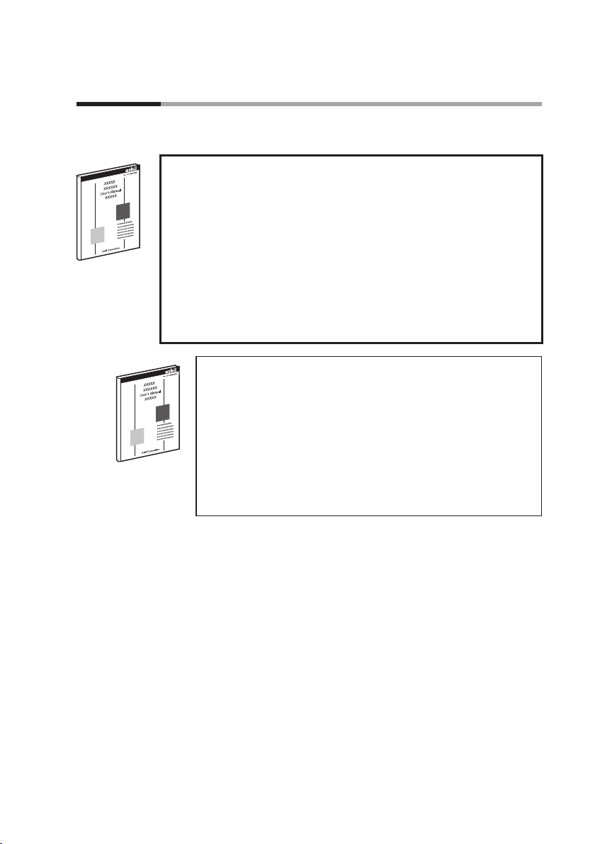
The Role of This Manual
A total of 2 different manuals are available for the MQV. Read them as necessary for your specific
requirements. If a manual you require is not available, contact the azbil Group or its dealer.
Digital Mass Flow Controller for Hydrogen and Helium Gases
Model MQV9020/9050/9500/0005/0010/0050/0200 User’s Manual
Manual No. CP-SP-1205E
This manual.
Personnel who are using the MQV digital mass flow controller (for
hydrogen and helium gases) for the first time or who are in charge of
hardware design and/or maintenance of equipment containing the
MQV should read this manual thoroughly.
This manual gives an overview of the product, describes installation,
wiring, operation, maintenance, and troubleshooting, and gives hardware specifications.
Digital Mass Flow Controller MQV9005/9020/9050/9200/
9500/0002/0005/0010/0020/0050/0100/0200/0500 User’s
Manual for Communication Functions
Manual No. CP-SP-1197E
Personnel who use this device’s communications functions
should read this manual.
The manual gives an overview of communications, describes
wiring, transmission protocols, communications data, and troubleshooting, and gives communications specifications.
v
Page 8

Organization of the Manual
This manual is organized as follows.
Chapter 1. INTRODUCTION
This chapter briefly describes this device and its features, and gives a
model selection guide.
Chapter 2. NAMES AND FUNCTIONS OF PARTS
This chapter describes the names and functions of this device’s parts.
Chapter 3. MOUNTING AND WIRING
This chapter describes installation, mounting, wiring and initial settings of this device.
Chapter 4. BASIC OPERATION
This chapter gives the basis of how to operate this device.
Chapter 5. ADVANCED OPERATION
This chapter describes how to set functions, parameters, device information display, and flow rate range.
Chapter 6. TROUBLESHOOTING
This chapter describes how to investigate and remedy trouble that
may occur during operation of this device.
Chapter 7. SPECIFICATIONS
This chapter describes the device’s specifications and external
dimensions.
vi
Page 9

Contents
Conventions Used in This Manual
Safety Precautions
The Role of This Manual
Organization of the Manual
Contents
Chapter 1. INTRODUCTION
Introduction
Features 1-1
Functions 1-2
Model selection guide 1-7
Basic operation and advanced operation 1-8
1-1
1-1
Chapter 2. NAMES AND FUNCTIONS OF PARTS 2-1
Display
2-1
Chapter 3. MOUNTING AND WIRING 3-1
Mounting
Piping 3-7
Wiring 3-8
3-2
Chapter 4. BASIC OPERATION 4-1
4-1 Switching Displays
Basic operation 4-1
4-2 Setting the Flow Rate 4-4
Digital flow rate setup 4-5
Flow rate setup by external contact input (Advanced use) 4-7
Flow rate setup by external 3-way switching input (Advanced use) 4-8
Analog flow rate setup 4-9
4-3 Selecting the Operating Mode 4-10
Operating mode selection 4-10
Operating mode display 4-10
4-1
Chapter 5. ADVANCED OPERATION 5-1
Setup mode transition operation
5-1 Functions 5-2
Setup method 5-2
Function setup items 5-3
5-1
vii
Page 10

5-2 Parameters 5-12
Parameter setup item list 5-13
5-3 Device Information Display 5-16
Setup method 5-16
Device information display item 5-17
5-4 Flow Rate Range 5-18
Setup resolution in the analog setup 5-19
Chapter 6. TROUBLESHOOTING 6-1
Alarm code display
Troubleshooting guide 6-3
6-1
Chapter 7. SPECIFICATIONS 7-1
Individual specifications
Korea Certification Mark 7-8
Gas type and control range 7-9
China RoHS 7-9
Relationship between differential pressure and flow rate (For
Hydrogen) 7-10
Relationship between differential pressure and flow rate (For Helium) 7-11
Optional parts (sold separately) 7-12
External dimensions 7-13
7-1
viii
Page 11
Chapter 1. INTRODUCTION
function)
Introduction
MQV high performance, digital mass flow controllers with advanced
functions have been developed for the general industrial application.
They feature flow rate control with high speed and wide range ability.
MQV controllers integrate three component technologies: the ultra
quick response μF (Micro Flow) thermal flow sensor, made with proprietary Azbil Corporation technology, a proportional solenoid valve,
and advanced actuator control technology.
Integrating these technologies has achieved a high-speed control with
low differential pressure.
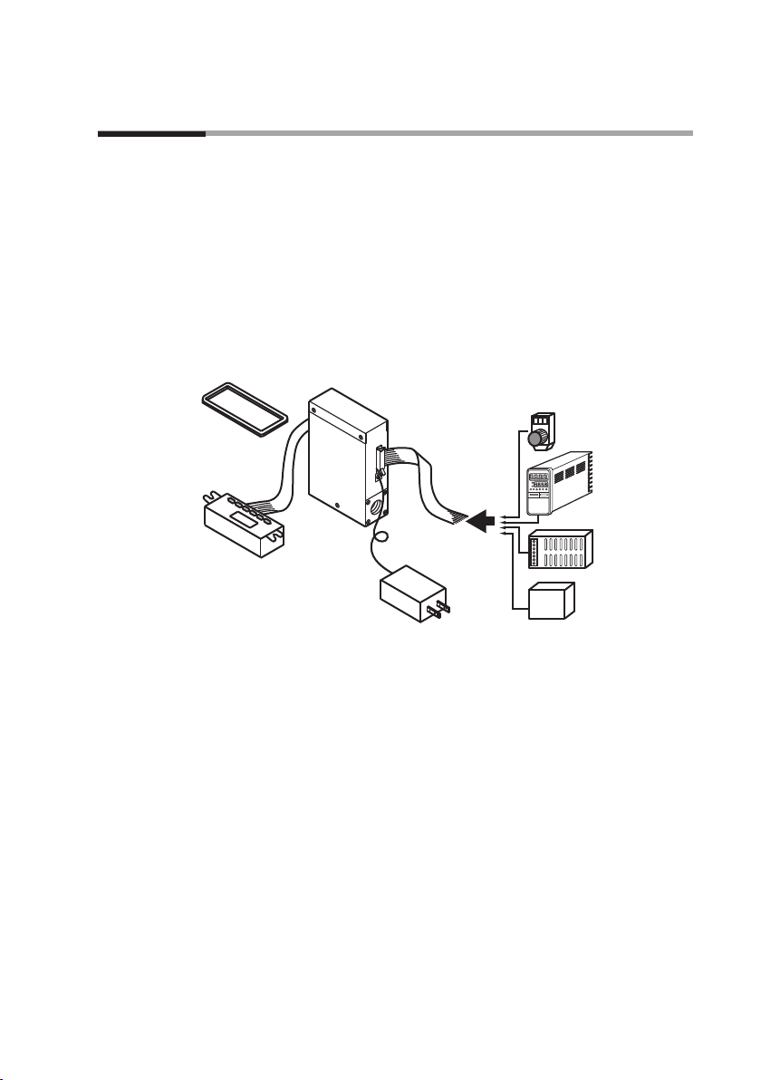
Front cover for
separate display
(sold separately)
Separate display unit
MQV
Cable with dedicated
connector (sold separately)
AC adapter
(sold separately)
Potentiometer (sold separately)
for setting ow rate
For details see page 7-17.
Controller
(e.g. SDC25/26)
24 V DC power supply
(e.g. WN790A)
RS-485 device
for models supporting
optional RS-485
communications
Features
Device Configuration
• High-speed controllability
Fast response of 300 ms or less*
(500ms for the MQV9020/9050.)
* Response time is the time required for the controlled flow rate to
reach ±2 % of the set value, starting from the fully closed state or
from when the set value is changed during control.
• Low differential pressure operation
MQV controllers can operate at a low differential pressure of 50kPa
or less.
• Wide control range
Wide control range of 1 to 100 % FS
• Wide product line-up
There are two types of models, those with integrated display and
those with separate display. On models with separate display, the
display unit can be detached to allow remote operation via the dedicated 2 m cable.
1-1
Page 12

Chapter 1. INTRODUCTION
Functions
• User-friendly
Runs on a general-purpose 24 V DC power supply, and the MQV's
internal power circuit and input/output circuits are isolated. When
multiple MQV are driven through the analog inputs and outputs,
as with a PLC, they can all use a common power supply even if the
PLC's analog modules are not isolated by channel. Therefore, even
without individual power supplies for each device, problems with
one circuit do not affect adjacent ones. Also provided is a handy AC
adapter (sold separately) for easy use in the laboratory.
• Display direction can be changed (models with integrated display only)
The direction of the display can be rotated 180° to match the direction of the gas flow, in case it was mounted the other way.
• Improved design (models with separate display only)
A front cover (sold separately) hides the mounting screws of the
separate display on the panel surface and improves the appearance.
• Various additional functions
The functions listed below are all standard.
All MQV models have the functions described below. For function
setup,
•
Chapter 5. ADVANCED OPERATION
Multi-setup (function setup
C-04
)
Quickly switch to one of eight preset flow set value by key operation or external input. If “Switching of SP No.” is set to external
3-way switching input, up to three set values can be switched.
•
Gas type switching (function setup
C-18, C-26
)
The gas type to be used can be selected from the standard compatible gases by key operation. Additionally, two kinds of gas type settings can be changed by external contact input.
•
Gas type setup (function setup
C-18
)
The user can set gas type conversion factors for gases other than
the standard compatible gases, and for mixed gases.
•
Control flow rate range setting (function setup
C-24, C-25
)
The control flow range can be changed to the desired range (10 to
100 % of the flow range at factory setting) in units of 1 % FS. The
setup and display resolution levels can be improved by reducing
the control flow range. Additionally, two kinds of control flow
ranges can be switched through external contact input.
1-2
Page 13

Chapter 1. INTRODUCTION
•
Direct setup (function setup
C-2 1
)
When changing the flow set value by key input, the controlled
flow rate can follow the set value while changes are being made
(the flow set value can be changed quickly). This function is useful when the user frequently changes set value, for example when
adjusting the flow set value during a trial run.
•
SP ramp control (function setup
C-27
)
This function is used to set the set value change ramp amount
(the rate of change per second) to a constant value for the start of
control and for set value changes. With this function, the set value
change ramp amount can be set more precisely than with the slow
start function. Two different types of ramps can be set, and there
are the following 2 control modes:
• SP ramp control 1
In SP ramp-up: Ramp 1
In SP ramp-down: Ramp 2
• SP ramp control 2
In external contact OFF: Ramp 1
In external contact ON: Ramp 2
•
SP limit (function setup
C-35
)
The lower and upper limits of the set value range can be set to desired levels. (This prevents mistaken high/low settings.)
•
Slow start (function setup
C-1 7
)
Sudden changes in the controlled flow rate, when control is started
or when the set value is changed, can be suppressed. The control
speed can be changed in eight stages within a range of about 1 to 6
seconds.
•
Flow rate totalization (function setup
C-09
to
C-12
)
MQV9020/9050: in 1 mL units
MQV9500: in 0.01 L units
MQV0005: in 0.1 L units
MQV0010/0050: in 1 L units
MQV0200: in 0.01 m
3
units
Integrated flow count can be up to eight digits long (to 99,999,999)
for each unit. (Display alternates between first and last 4 digits.)
The count can be reset by key operation or external contact input.
Use of external contact input makes it possible to remotely operate
the start, temporary stop, and reset of totalization. When resetting
the integrated count by key operation, the count restarts automatically after it has been reset. On the other hand, when resetting
with the external contact input (by contact ON), the count restarts
when the contact is turned OFF.
1-3
Page 14

Chapter 1. INTRODUCTION
•
Event lamp lighting/output (function setup
C-07, C-08
)
Two of the event types listed below can be selected. Output ON
delay time can also be set (but delay cannot be set for totalizer
pulse output).
•
Integrated flow event output (when the integrated flow event setting is exceeded.)
•
Totalized pulse output (pulse can be output for each totalizing
flow display unit.)
•
OK output (the control flow rate is within the set value ± allowable range.)
•
Flow rate upper or lower limit output (output in comparison
with optional upper or lower limit flow rate set value )
•
Output mode (The four modes — control / fully open / control
or fully open / fully closed — can be identified and output.)
•
OK lamp ON/output (function setup
C-07, C-08
)
The OK lamp can be set to light when the control flow rate is
within the set value ± allowable range. This function is very handy
for verifying at a glance whether or not there is a proper response
to a new set value after its value is changed. OK lamp output can
also be used as an interlock signal for subsequent processes by assigning it to event output and including it in a sequence program.
•
PV filter (function setup
C-23
)
This function is used to average the detected instantaneous flow
rates (control flow rates). It can also reduce the effect of slight
pressure fluctuations.
•
Control dead band setup (prevention of valve operation) (function setup
)
C-22
This function is used to stop the valve from driving as long as the
control flow rate is within the OK range. Additionally, the OK
range (width of dead band) can be set to the desired level.
•
Valve amperage display (function setup
C-20
)
The electric current supplied to the valve can be displayed in units
of 0.0 to 100.0 %. Additionally, use of the valve amperage alarm
detection function makes it possible to detect an inlet pressure
change or clogging of the piping at the outlet.
•
Gas type external switching (function setup C- 10 to C- 12, C-
18, C-26
)
Two preset types of gases (including one with a user-determined gas
type conversion factor) can be switched by external contact input.
•
Control flow rate range external switching (function setup
to C- 12,
C-24, C-25
)
C-10
Two preset control flow ranges can be switched by external contact
input.
1-4
Page 15

Chapter 1. INTRODUCTION
•
PV forced zero (function setup
C-29
)
This function forcibly sets the detected instantaneous flow rate to
0 (zero) after the delay time elapses when the flow rate setpoint has
been set to 0 (zero) or the valve mode has been changed to fully
closed. This function makes it possible to ignore the deviation of
the instantaneous flow rate zero point caused by inclination of the
piping or the like.
•
Flow rate display unit change (function setup
C-37
)
This function is used to change the flow rate display unit to L/
min or mL/min of the MQV9500/0005. When multiple devices
are used side-by-side, this function can make the flow rate display
units uniform.
•
PV display decimal point change (function setup
C-38
)
This function is used to shift the decimal point position of the instantaneous flow rate display one digit left or right. When multiple
devices are used sideby- side, the number of digits after the decimal point of the flow rate display can be made uniform.
•
Valve forcibly open or close (function setup
C-02, C-09
to C- 12)
This function is used to forcibly open or close the valve fully by
key operation, external contact input, or external 3-way switching
input.
•
Automatic shut-off (function setup C- 13, C- 16)
The valve can be shut off automatically under the following conditions:
(1) When the totalized flow count reaches the preset value.
(2) When one of the alarms, including flow rate alarms, is triggered.
•
ALM (alarm) lamp ON/output/valve shut-off (function setup
C- 16, C-20
)
C-15
The alarm output can be set for high and low deviations in the
flow set value and instantaneous flow rate. Additionally, an alarm
judgment delay time can also be set. If a flow rate alarm occurs or
if an alarm occurs during self diagnosis of this controller, the valve
can be forced fully closed or opened.
,
Handling Precautions
•
The valve on this device cannot completely shut off.
•
If complete shut off is required, provide a shutoff valve
separately.
•
Automatic reset of totalized flow at start of control function
(function setup C- 14)
Start of control and reset of totalized flow count can be done
simultaneously by a single action (by key or external switching
input). Combining this function with the automatic shut-off function described above is handy for shutting the valve off in cases
where a fixed totalized flow amount is counted repeatedly.
1-5
Page 16

Chapter 1. INTRODUCTION
•
Analog scaling (function setup
C-28
)
This function is used to optionally change the flow rate (between
10% FS and 100 % FS) corresponding to 100 % FS analog input/
output (5 V or 20 mA).
•
Analog input (flow set value) range selection (function setup
C-05, C-09
)
In analog setup, the desired input range can be selected from those
shown below either by key operation or by external 3-way switching input. When doing so, the voltage input and current input
are selected automatically, as they are linked with the settings of
function setup
when the voltage output (0 to 5 V or 1 to 5 V) is selected in
(analog output type selection). For example,
C-06
C-06
the voltage input is selected automatically. Likewise, when the current output (0 to 20 mA or 4 to 20 mA output) is selected, the current input is selected automatically.
(1) Internal reference 0 to 5 V input*/External reference 0 to 20mA input
(2) External reference 0 to 5 V input/External reference 0 to 20mA input
(3) External reference 1 to 5 V input/External reference 4 to 20mA input
* 0–5 V internal-reference is used when the 5 V output termi-
nal (pin No. 20) of this controller is used as the reference.
•
Analog output type/range selection (function setup
C-06, C-09
Output can be set either to instantaneous flow rate (PV) or flow set
value (SP). Furthermore, a voltage/current output range can be selected from (1) to (4) shown below by key operation. Additionally,
(1)/(2) or (3)/(4) can be changed through the external 3-way
switching input. (Combinations are switched because of linkage
with the analog input range selection.)
Instantaneous flow rate (PV) output Flow set value (SP) output
(1) 0 to 5 V output (1) 0 to 5 V output
(2) 1 to 5 V output (2) 1 to 5 V output
(3) 0 to 20 mA output (3) 0 to 20 mA output
(4) 4 to 20 mA output (4) 4 to 20 mA output
,
)
1-6
Page 17
Chapter 1. INTRODUCTION
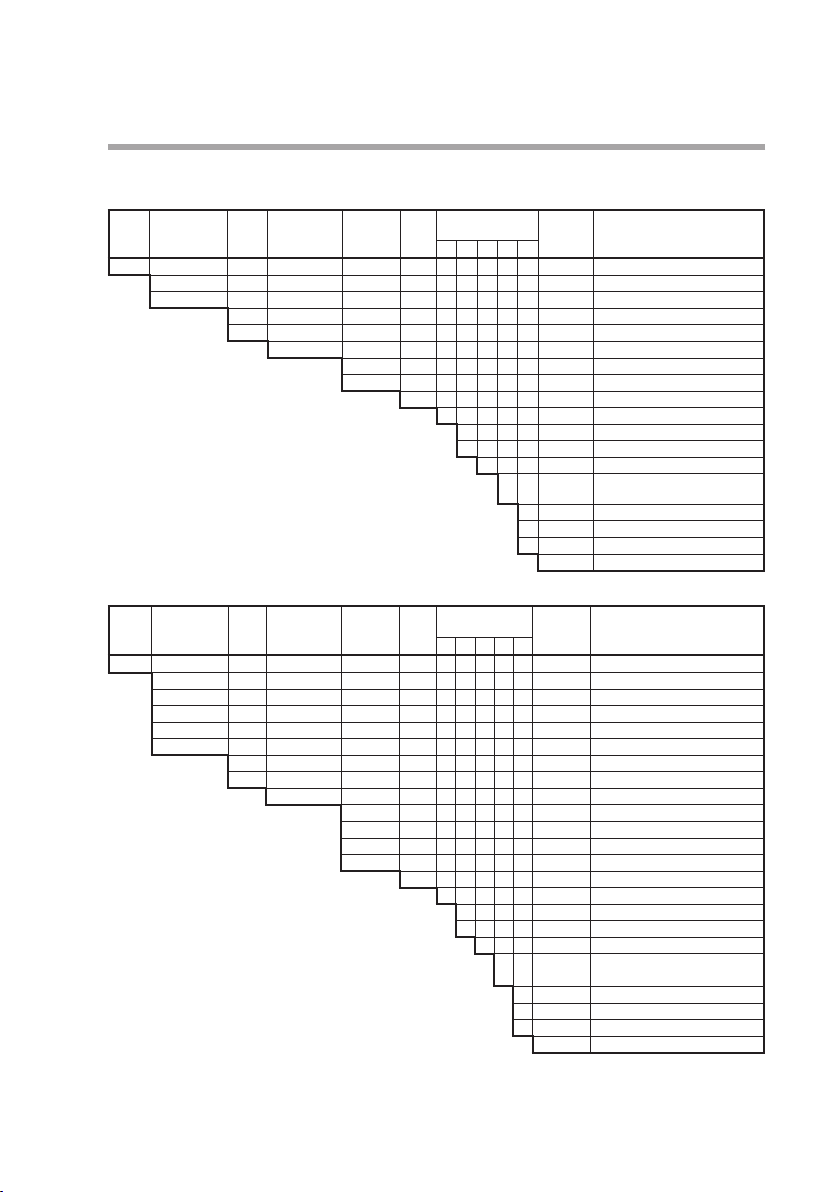
Model selection guide
z MQV9020/9050
Basic
model
Nos.
Standard con-
trol flowrate
ange
r
Display
Material of
gas-contact-
ing parts
Connection
method
MQV Digital mass flow controller
9020 0.2–20.0 mL/min (standard)
9050 0.4–50.0 mL/min (standard)
B
C
S SUS316
S 1/4" Swagelok
V 1/4" VCR
z MQV9500/0005/0010/0050/0200
Basic
Standard con-
model
trol flowrate
Nos.
ange
r
MQV Digital mass-flow controller
9500 0.004–0.500 L/min (standard)
0005 0.04–5.00 L/min (standard)
0010 0.10–10.00 L/min (standard)
0050 0.4–50.0 L/min (standard)
0200 2–200 L/min (standard)
Notes: *1. The unit L/min (standard) indicates the volumetric flow rate per minute converted to 20 °C, 101.325 kPa (one
*2. This device is set initially for hydrogen gas use at the factory. It can be used for helium gas by changing the gas
atmosphere). The reference temperature can also be changed to 0 °C, 25 °C and 35 °C.
type setting.
Display
B
C
Material of
gas-contact-
ing parts
Connection
method
S SUS316
R Rc 1/4"
S 1/4" Swagelok
V 1/4" VCR
U 9/16-18UNF
Gas
type
Optional
functions
1 2 3 4 5
Appended
No.
Description
Integrated display (body length: 90 mm)
Seprate display (body length: 90 mm)
H Hydrogen
0 Without optional functions
0 Without optional functions
1
Model with RS-485 communications (CPL)
0 Without optional functions
1 Gas-contacting parts treated
to be oil free
0 Without optional functions
D With inspection certificate
Y With traceability certificate
0 Product version
Optional
Gas
type
functions
1 2 3 4 5
Appended
No.
Description
Integrated display (body length 90 mm)
Separate display (body length 90 mm)
H Hydrogen
0 Without optional functions
0 Without optional functions
1
Model with RS-485 communications (CPL)
0 Without optional functions
1 Gas- contacting parts treated
to be oil free
0 Without optional functions
D With inspection certificate
Y With traceability certificate
0 Product version
1-7
*1
*1
*2
*1
*1
*1
*1
*1
*2
Page 18
Chapter 1. INTRODUCTION
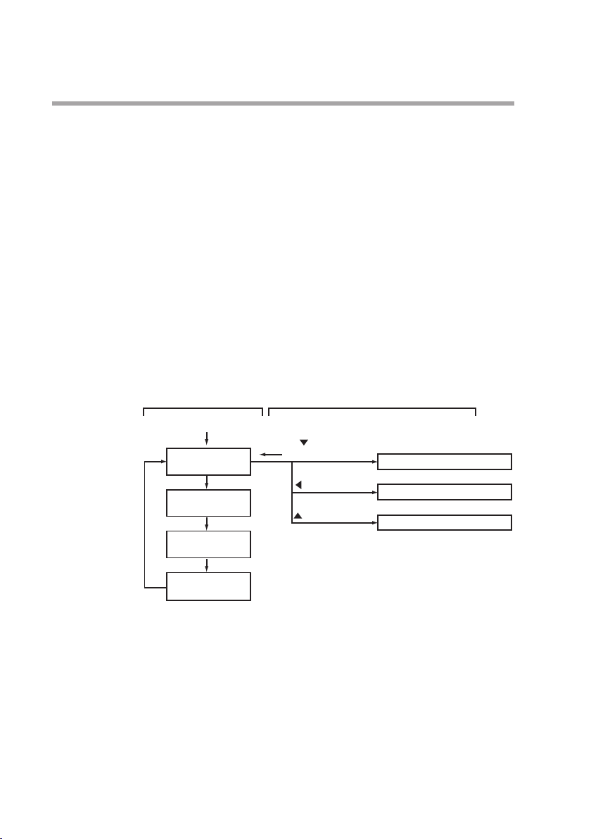
Basic operation and advanced operation
This device provides two kinds of operations, basic operation and
advanced operation. Basic operation is the state of the device during
normal use. In basic operation, the contents of the 7-segment display
can be changed to show instantaneous flow rate, flow set value, totalized flow value, or amperage to the valve in normal operation mode.
Also, how to set the flow set value is described in the basic operation
part.
Advanced operation is for selecting various functions or setting parameters of the device. When the device is used with the factory settings, no setup operation is needed. However, to change the gas type,
set a range, set an external contact input, set upper and lower alarm
limits, or set communication conditions (for models with communication functions), it is necessary to configure various settings using
advanced operation. The diagram below gives an outline of operation
flow. Basic and advanced operation are described in Chapters 4 and
5, respectively.
Basic operation Advanced operation
Power ON
DISP key
DISP key
DISP key
DISP key
DISP key
Instantaneous ow
rate display
Flow set value display
Totalized ow display
Valve amperage display
key + ENT key
(3 s or more)
key (3 s or more)
key (3 s or more)
Function setup mode
Parameter setup mode
Device information display mode
1-8
Page 19

Chapter 2.
NAMES AND FUNCTIONS OF PARTS
Display
OK lamp:
Lit when the deviation between the ow set value
and instantaneous ow rate is in the allowable range.
Set the allowable range in the parameter setup.
(For details on how to set parameters, see .)
ALM lamp:
7-segment display:
Displays the instantaneous ow rate,
ow set value, totalized ow, amperage
to the valve and the operating mode.
It also displays parameter setup values, function
setup values and details of alarms.
SP lamp:
Lit when the ow rate
setpoint is displayed.
PV lamp:
Lit when the instantaneous ow
rate is displayed.
OK ALM EV1 EV2
SP
PV
RUN ENT DISP
*1 This lamp is used for mL or m3 instead of L on some models.
*2 This lamp is used for mL/min instead of L/min on some models.
Lit when an alarm occurs.
EV1 lamp:
Lit when event 1 output is ON.
EV2 lamp:
Lit when event 2 output is ON.
Digital
Mass Flow
Controller
L
L/min
[DISP] key:
Use this key to switch the details displayed
on the 7-segment display.
[ENT] key:
Use this key to x and store the set value to
memory.
Also use it to reset the cumulative ow and to
reset alarm and move to the function setup mode.
[ ]
key:
[ ]
key:
[ ]
[RUN] key:
Use this key to change the operating mode.
page 5-12
L lamp *1:
Lit when the totalized ow is displayed.
Blinks when the cumulative
ow event occurs.
L/min lamp*2:
Lit when the instantaneous ow rate
or ow set value is displayed.
Use this key to increment the setting value.
Additionally, this key is used to change to
the device information display mode.
Use this key to decrement the setting value.
Also use it to move to the function setup mode.
key:
Use this key to move to a desired digit
when changing setting value. Also use it to
move to the parameter setup mode.
Note
•
Technical terms used in this manual are defined as follows:
•
SP (setpoint): The flow set value (or flow rate set point)
•
PV (process variable): Instantaneous flow rate (or controlled flow rate)
•
Operating mode: One of 3 modes (valve fully closed/valve
control/
2-1
Page 20
Chapter 2. NAMES AND FUNCTIONS OF PARTS
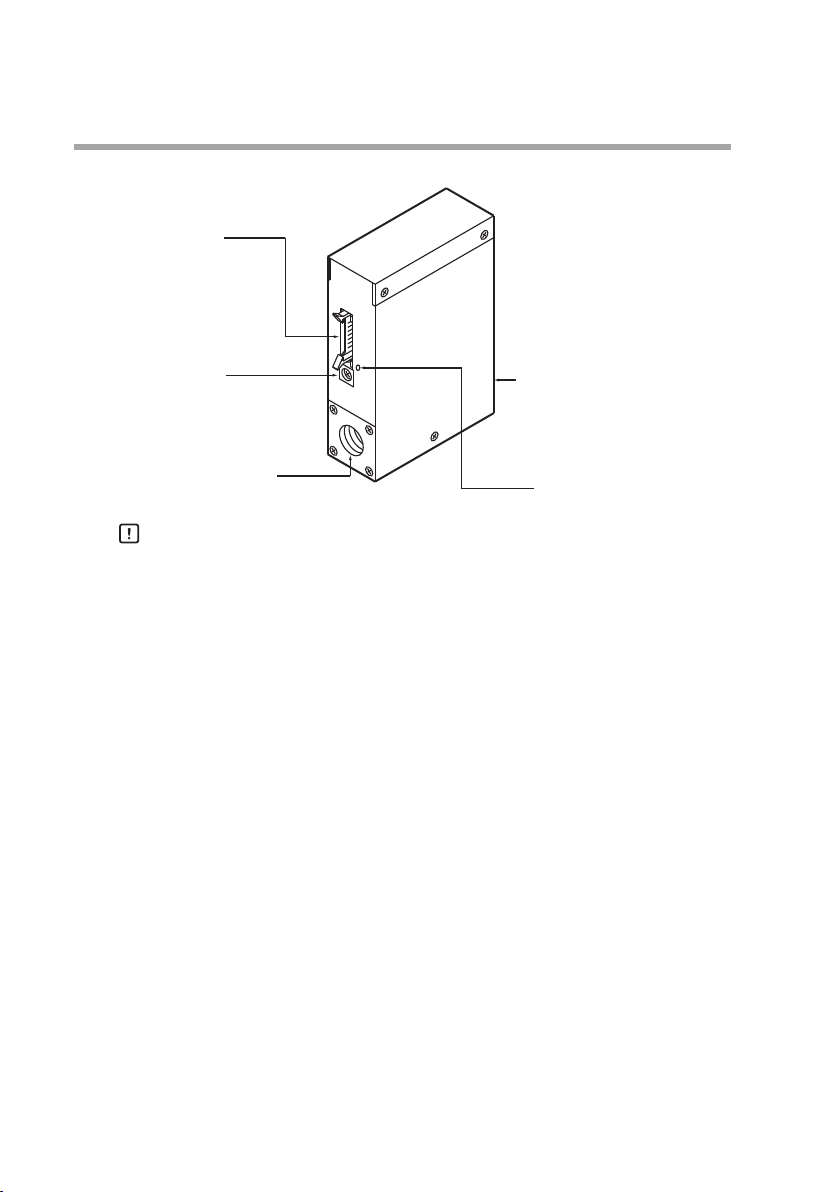
z Main unit (MQV9020/9050/9500/0005/0010/0050/0200)
Connector port:
This is used for I/O signals.
Use cable with dedicated
connector.
Jack for AC adapter:
Connect dedicated adapter here.
Model No.: 81446957-001
(24 V DC, 750 mA)
Pipe connection port (inlet):
This is the port through which
gas enters.
Handling Precautions
•
Pipe connection port (outlet):
This is the port from which
gas is discharged.
Jack for PC loader connection
The former AC adapter (model No. 81446682-001, 15 V DC/350mA)
can not be used with MQV.
2-2
Page 21
Chapter 3. MOUNTING AND WIRING
WARNING
Never allow gases that are within explosion limits (in particular, mixed gases within
explosion limits that contain hydrogen) to pass through this device. Doing so might
result in an explosion accidents.
When using this device for gases that contain hydrogen, be sure to purge the device
with an inert gas (such as nitrogen or argon) before use. Use without purging may
cause an explosion.
CAUTION
Check the product connections and pipe connections for leakage before use.
Also, check the connections for leakage regularly after the start of use.
It is the user’s responsibility to ensure that gas leaks can be reliably detected.
This is especially important if a dangerous gas is used.
Prevent foreign matter from entering the device. If rust, water droplet, oil mist, or
dust in the pipes enters the device, measurement or control error or damage might
occur.
If there is a possibility of foreign matter entering the device, provide a filter, strainer
or mist trap capable of eliminating foreign matter 0.1 μm or greater in diameter at the
upstream. Be sure to inspect and replace the filter at regular intervals.
This device is exclusively for hydrogen and helium gases. It cannot be used for control
or measurement of gases other than hydrogen, helium, and hydrogen-helium mixtures (excluding mixed gases within explosion limits). Oxygen cannot be measured
even if gascontacting sections of this device are oil-inhibited.
This device is set initially for hydrogen gas use at the factory. To use it for helium
gas or mixed gases, change the gas type setting. The use of this device for helium or
mixed gases without changing the gas type setting will result in a measurement error.
Use the device within the operating differential pressure range. Also, do not subject it
to pressure beyond the rated pressure resistance range. Doing so might damage it.
The valve on this device cannot completely shut a flow off. If complete shutoff is
required, provide a shutoff valve separately. When the external valve is closed, it
is necessary also to fully close the valve of the device using either of the following
methods:
• Set the flow rate setpoint to zero.
• Make the valve operation mode to fully closed.
If this valve remains in normal control status when the external shutoff valve is
closed (zero flow rate), there will be an excessively large flow as soon as the external
shutoff valve is opened. This excessive flow rate could activate the
erated by the sensor safety circuit). If the sensor safety circuit is activated, flow rate
measurement and flow control are not possible until the power is turned off and
back on again.
AL83
alarm (op-
3-1
Page 22

Chapter 3. MOUNTING AND WIRING
CAUTION
Before connecting pipes with Swagelok or VCR connections, check the precautions
in the instruction provided by the connecting joint manufacturer.
When purchasing a connecting joint, use the following made by Swagelok Co., Ltd:
1/4" Swagelok: SS-400-1-6STSC11
1/4" VCR: SS-4-VCR-1-00032SC11
The device is a precision instrument. Do not drop it or subject it to impact, or it
might be damaged.
Mounting
z Installation locations
Avoid mounting the device in the following locations:
• Locations subject to high and low temperature and humidity
• Locations whose atmospheres contain large amounts of dirt and
dust, salt, conductive substances such as iron powder, water droplet,
oil mist or organic solvents
• Locations subject to direct sunlight and rain
• Locations directly subject to mechanical vibration or shock
• Locations close to sources of electrical noise
• Locations where strong magnetic or electrical fields are generated
Handling Precautions
•
The valve of this device cannot completely shut a flow off. If complete shutoff is required, provide a shutoff valve separately.
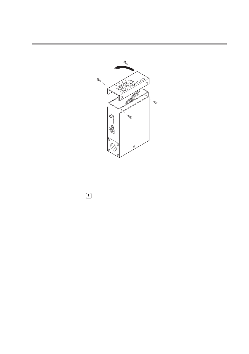
z Changing the display direction (models with integrated display only)
The display can be turned 180°, in case the controller has been
mounted with the display upside-down.
• Procedure
(1) Turn the power OFF.
(2) Remove the four screws holding the display.
3-2
Page 23
Chapter 3. MOUNTING AND WIRING
(3)
Lift up the display from the main unit, and turn it 180°
counterclockwise.
(4) Put the display back on the main unit, and fasten with the four
screws taken off in step (2).
(5) To return the display to its original position on the main unit,
turn it 180° clockwise.
Handling Precautions
•
Before changing the display direction, be sure to turn the power OFF
•
Prevent foreign objects from falling inside the main unit when
the display is taken off. Failure to do so might cause trouble or
malfunction.
•
Do not remove the connectors used inside the main unit.
.
3-3
Page 24
Chapter 3. MOUNTING AND WIRING
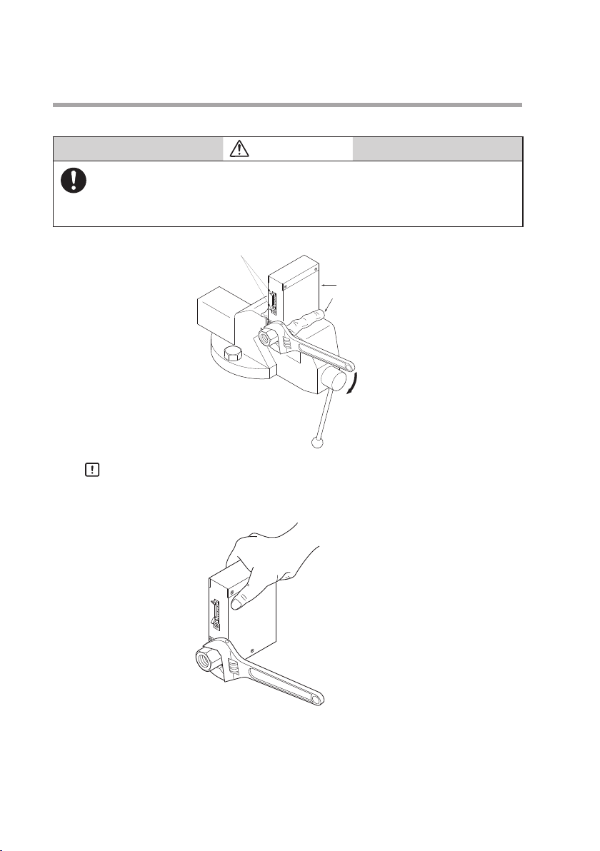
z Installing joints (UNF connections)
CAUTION
When installing joints (UNF connections), secure the lower part of the main
unit in a vise or the like gripped between rags to protect the finished surfaces,
and turn the joint to tighten. The device may be damaged if the lower main
unit is not secured.
Connector latches
main unit
Rag
3-4
Handling Precautions
•
Do not hold the top part of the main unit with your hand. Doing
so might deform the case.
Incorrect
•
Take special care not to damage the connector latches.
Page 25
Chapter 3. MOUNTING AND WIRING
z Installation procedure
CAUTION
Mount securely in order to prevent vibration. Otherwise, equipment failure
could result.
Mount the device horizontally. Do not mount it with the display facing down.
Doing so might cause measurement error or equipment failure.
MQV9020/9050/9500/0005/0010/0050/0200
Install the device with two M4 screws using the mounting holes on
the base of the device.
15
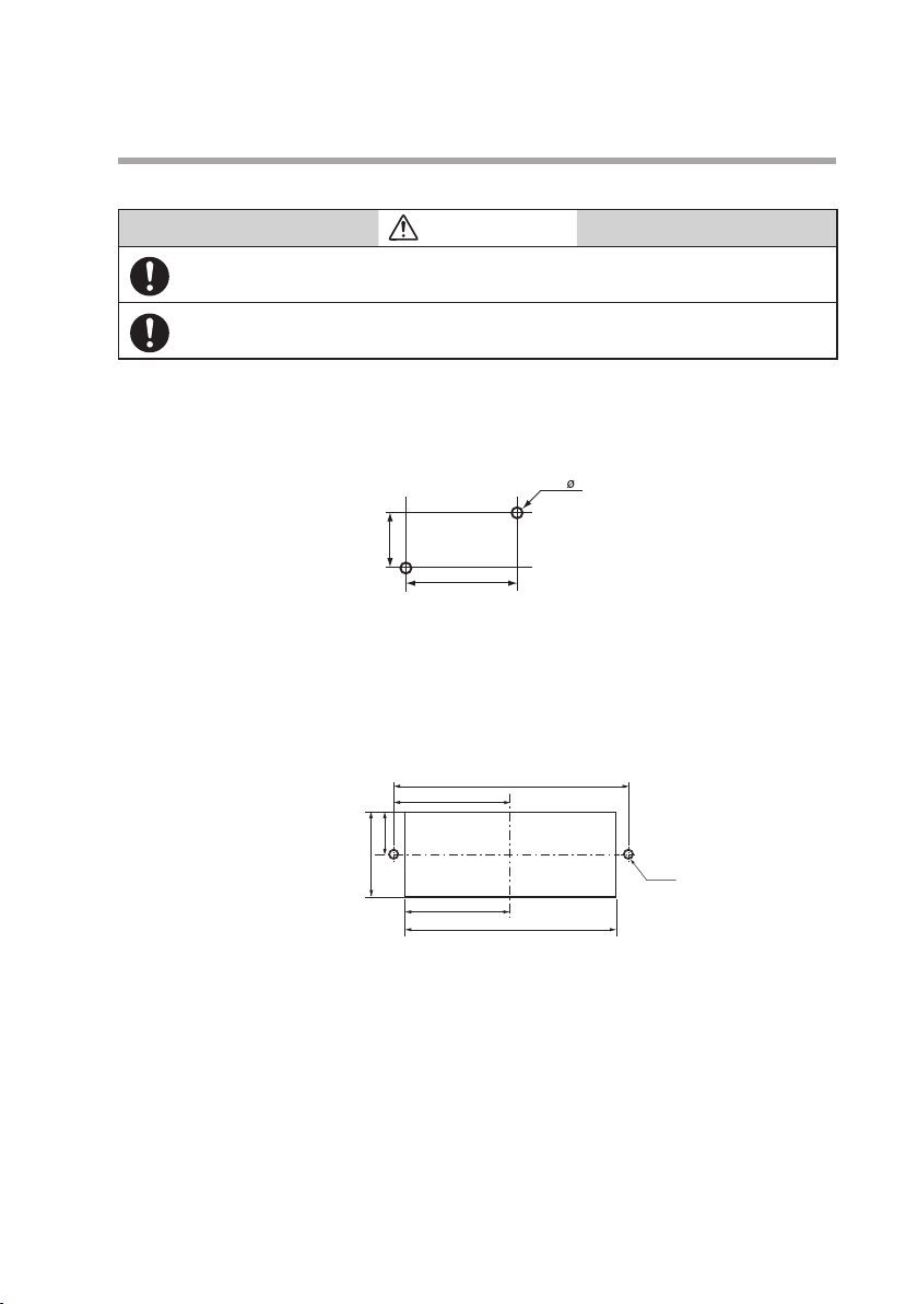
z Installing the separate display unit
For models with a separate display
(1) Make mounting holes in the panel according to the panel cutout
dimensions.
Panel cutout dimensions
Unit: mm
4.5
30
100±0.2
50±0.2
Unit: mm
17.5±0.2
35±0.2
45±0.2
90±0.2
M4 (2)
(2) Mount the display and secure it by tightening the screws.
3-5
Page 26
Chapter 3. MOUNTING AND WIRING
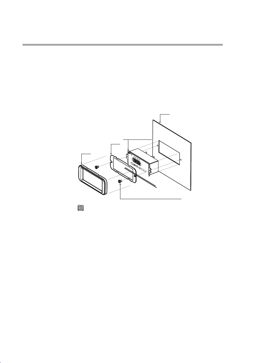
z Installing the front cover for the separate display unit
For models with a separate display, a front cover (decorative frame)
can be mounted. Use of this cover makes it possible to hide the
mounting screws, improving the appearance.
Items needed for installation
• Front cover (81446858-001), 1 set
• Phillips screwdriver
Separate display
unit
Plate
Mask
Panel
3-6
Mounting screws
(cross recessed head machine screws)
Note
•
The front cover set includes one mask, one plate, and two
mounting screws.
Procedure
(1) As shown in the figure, put the plate over the display panel, and
then secure it to the display by tightening the screws.
(2) Fit the mask onto the display to mount it.
Page 27
Chapter 3. MOUNTING AND WIRING
Piping
CAUTION
Mount the device horizontally. However, do not mount it with the display facing down.
Doing so might cause measurement error or equipment failure.
When making the pipe connections, hold the hexagonal part of the connector
section and turn the pipe to tighten. After connecting, check that there are no
gas leaks.
If using Rc connections, take care not to coat with too much sealant. Foreign
matter or burrs in the pipes may also cause measurement errors.
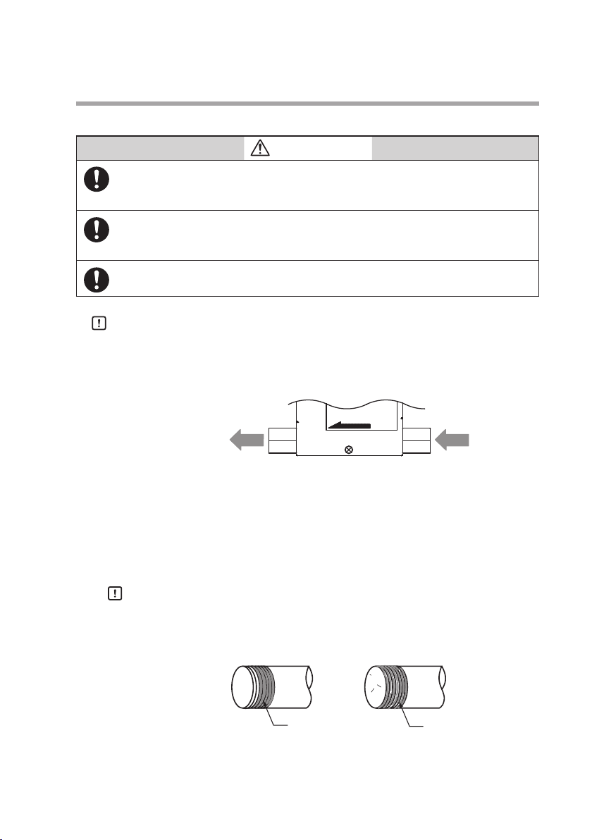
Handling Precautions
•
Make sure that the gas flows into the device in the direction indicated by the FLOW arrow on the main unit. Otherwise, the flow
rate cannot be controlled correctly.
FLOW
GasGas
•
Do not touch the pipe sections of a controller treated to be oilfree with your bare hands. Doing so will degrade the oil-free
treatment.
•
Do not hold the top part of the main unit with your hand when
connecting piping. Doing so might deform the case.
z Coating sealant (Rc connection)
Handling Precautions
•
Coat with an appropriate amount of sealant. Do not coat the top
two threads. Remove any dirt or burrs from inside the pipes.
Correct
Incorrect
Sealant
Sealant
3-7
Page 28

Chapter 3. MOUNTING AND WIRING
Wiring
CAUTION
Do not apply a negative voltage or a voltage exceeding 5V to the external
setup voltage input terminal. Doing so might cause malfunction or equipment
failure.
When using a relay for external contact input and/or external 3-way switching
input, always use a relay designed for micro-current use (with gold contacts).
Failure to do so could cause faulty contact, resulting in malfunction.
If there is a risk of a power surge caused by lightning, use Azbil Corporation's
SurgeNon to prevent possible fire or equipment failure.
Gas type switching by external contact input, flow rate switching, and analog input/output voltage range switching by external 3-way input switching
should be done only after setting the operation mode to fully closed. Switching
while controlling could cause large fluctuations.
Be sure to check that the wiring is correct before turning the power on.
Incorrect wiring could cause damage or malfunction.
Do not apply excessive force to cables or connectors when connector cables
or the AC adapter is attached. Excessive force may damage the connectors or
circuit board.
z Connector pin layout
20 19
Connector model No. (device side): HIF3BA-20PA-2.54DS
Manufacturer: HIROSE ELECTRIC CO., LTD.
2
View from connector insertion side
1
z Table of compatible connectors (all made by HIROSE ELECTRIC CO., LTD.)
Connector type
Contact crimp type HIF3BA-20D-2.54C HIF3-2226SCC AWG#22 to #26
Cable clamp type HIF3BA-20D-2.54R Not required AWG#28 (flat cable only)
Compatible connec-
tor model No.
Compatible contact
model No.
Compatible wire
(single wire allowed)
3-8
Page 29

Chapter 3. MOUNTING AND WIRING
z Connector signal names
Pin No. Signal name Description Notes
20 +5 V (5 mA max.) 5 V DC reference voltage output 5 mA max.
19 FLOW OUT Instantaneous flow rate (PV) or
flow rate setpoint (SP) output
18 A.GND Analog ground Analog signal common
17 FLOW SP INPUT Setpoint flow rate (SP) voltage
input
16 MODE INPUT External 3-way switching input 3-way switching input
15 DI3 External contact input 3 2-way switching input
14 DI2 External contact input 2
13 DI1 External contact input 1
12 EV2 OUT Event output 2 Open collector non-insulated
11 EV1 OUT Event output 1
10 ALM OUT Alarm output
9 D.GND Digital ground Digital signal common
8 DB RS-485 communications DB Do not connect on models
7 DA RS-485 communications DA
6 D.GND Digital ground Digital signal common
5 TEST For test Do not use.
4 POWER GND Power supply ground Connect two wires each in
3 POWER GND Power supply ground
2 POWER (24 V) Power supply + (24 V DC)
1 POWER (24 V) Power supply + (24 V DC)
0 to 5 V/1 to 5 V/0 to 20 mA/ 4
to 20 mA output
0 to 5 V/1 to 5 V/0 to 20 mA/ 4
to 20 mA input
(OPEN/GND/5 V)
(OPEN/GND)
output
without the communications
function.
parallel to the power supply to reduce voltage drop
caused by wiring resistance.
z Wiring
Note
• Power supply
POWER GND
4
POWER GND
3
2
+-
24 V DC
POWER (24 V)
1
POWER (24 V)
• RS-485 communications (for models with optional RS-485 only)
DB
DA
SG
•
For details on the connection method of RS-485 communication,
8
DB
7
DA
or 9 D.GND
6
please refer to Digital Mass Flow Controller Model MQV9005/9020/9
050/9200/9500/0002/0010/0020/0050/0100/0200/0500 User's Manual
for Communication Functions (CP- SP-1197E).
3-9
Page 30

Chapter 3. MOUNTING AND WIRING
• Alarm output/event output
Handling Precautions
•
Take special care that the event and alarm outputs do not
exceed the output rating of the device. Additionally, when
driving a relay, use an appropriate coil surge absorption
diode built-in relay. Failure to do so might cause the device to
malfunction.
• External contact input
Handling Precautions
•
When switching by relay contact, use an appropriate relay
intended for micro-current use (with gold contacts). Failure to
do so could cause faulty contact, resulting in malfunction.
Load
Load
Load
+ -
EV2 OUT
12
11
EV1 OUT
10
ALM OUT
9
or 6 D.GND
DI3
15
DI2
14
13
DI1
9
or 6 D.GND
3-10
• Analog I/O
0 to 5 V/1 to 5 V
0 to 20 mA/4 to 20 mA
Output
+
—
+
0 to 5 V/1 to 5 V
0 to 20 mA/4 to 20 mA
Input
—
• When using potentiometer (0 to 5 V)
20
+5 V
18
A.GND (0 V)
FLOW SP INPUT
17
19
FLOW OUT
A.GND
18
FLOW SP INPUT
17
Page 31

• External 3-way switching input
5 V
0 V
OPEN
Handling Precautions
•
When switching by relay, use an appropriate relay intended for
microcurrent use (with gold contacts). Failure to do so could
cause faulty contact, resulting in malfunction.
Operation of external 3-way switching input
20
+5 V
A.GND (0 V)
18
MODE INPUT
16
Chapter 3. MOUNTING AND WIRING
Input state of pin No.16
OPEN 0 V 5 V
Assigned function
Switching of operating mode 1 Control Fully closed Fully open
Switching of operating mode 2 Fully closed Control Fully open
Switching of SP No.
Switching of totalizing
SP-0 SP-1 SP-2
Continue counting Reset Stop counting
operation
Switching of analog
I/O voltage range
Input Internal
reference*
0 to 5 V or
external
External
reference
0 to 5 V or
0 to 20 mA
External
reference
1 to 5 V or
4 to 20 mA
reference
0 to 20 mA
Output 0 to 5 V/0 to 20 mA 0 to 5 V/0 to 20 mA 1 to 5 V/4 to 20 mA
* "Internal reference" refers to the use of the 5 V DC reference voltage pin (No. 20) on this device,
and is used when the setting value is set by an externally connected potentiometer.
Note
•
For details on how to assign external 3-way switching input functions,
Chapter 5. ADVANCED OPERATION
3-11
Page 32

Chapter 3. MOUNTING AND WIRING
z Example of wiring
Instantaneous owrate output
Potentiometer
(5 kΩ)
0 V
Event output 2
Event output 1
Alarm output
(Output common)
Power supply
(24 V DC)
+
-
+5 V
OPEN
-
+
DB
DA
SG
+5 V (5 mA max.)
FLOW OUT
A.GND
FLOW SP INPUT
MODE INPUT
DI3
DI2
DI1
EV2
EV1
ALM OUT
D.GND
DB
DA
D. GND
TEST
POWER GND
POWER GND
POWER (24 V)
POWER (24 V)
20
19
18
17
16
15
14
13
12
11
10
9
8
7
6
5
4
3
2
1
Internal circuit
Input/output circuit
Power circuit
Handling Precautions
3-12
AC adapter input
•
Do not input any signal to pin No. 5.
•
The power circuit is isolated from the input/output circuit inside
-
this device.
+
•
Even though the analog GND and digital GND are connected internally, always carry out the grounding wiring individually.
•
When the AC adapter plug is inserted into the AC adapter power
supply terminal, the power supply changes from the DC power
supply to the AC adapter.
•
The former AC adapter 81446682-001 (15 V DC, 350 mA) cannot
be used with this MQV.
Page 33

z Connector terminal block
Sometimes two or more connections must be made to the same pin
during wiring. In this case, use a connector terminal block. If you
need a 20-core cable for the connectors on the device and connector
terminal block, contact the azbil Group or your dealer.
Note
•
Recommended connector terminal block
Manufacturer: Toyo Giken
Model: PCN-1H-20
This terminal block can be mounted directly on a DIN rail.
The following table shows the correspondence between connector
pin Nos. and terminal block Nos:
Handling Precautions
•
For details regarding the cable with connector on both ends,
contact the azbil Group.(The optional 81446681-001 and
81446951-001 connectors cannot be used to connect to the
connector terminal block.)
•
The specifications of the recommended connector terminal
block are subject to change. Contact the manufacturer beforehand for details.
Pin No. Terminal block No.
20 B-10
19 A-10
18 B-9
17 A-9
16 B-8
15 A-8
14 B-7
13 A-7
12 B-6
11 A-6
10 B-5
9 A-5
8 B-4
7 A-4
6 B-3
5 A-3
4 B-2
3 A-2
2 B-1
1 A-1
Chapter 3. MOUNTING AND WIRING
Mounting connector
HIROSE ELECTRIC CO., LTD., HIF3BA-20PA-2.54DSA
Compatible connector (other side)
HIROSE ELECTRIC CO., LTD., HIF3BA-20D-2.54R
MQV
20
2
19
Cable with connector
on both ends
Connector terminal
block
1
3-13
Page 34

Page 35

Chapter 4. BASIC OPERATION
4-1 Switching Displays
CAUTION
Do not operate the console keys using a sharp object such as a mechanical pencil or screwdriver. Doing so might damage the console.
Basic operation
Basic operation is used to change the display to instantaneous flow
rate (PV), flow set value (SP), totalized flow value, or valve amperage.
Normally, when the power is turned ON, the instantaneous flow rate
is displayed in basic operation mode. When this is the case, operating the [DISP] key changes the contents of the 7-segment display as
described below.
Power ON
Instantaneous ow rate display (PV and L/min lamps lit)
DISP key
Flow set value display (SP and L/min lamps lit)
DISP key
Totalized ow display (L lamp lit)
DISP key
Valve amperage display (SP, PV, L, and L/min lamps go out)
DISP key
Handling Precautions
•
If there is no operator input for approximately 10 seconds while
the flow set value is being displayed, the display automatically
reverts to the instantaneous flow rate display.
•
The "L" lamp is labeled "mL" on the MQV9020/9050 or "m3" on
the MQV0200. The "L/min" lamp is labeled "mL/min" on the
MQV9020/9050.
z Indicating instantaneous flow rate (PV display)
When the power is turned ON, the PV and L/min lamps light, and the
instantaneous flow rate is indicated on the display.
Handling Precautions
•
When the operating mode is set to fully closed, and the flow
rate is zero, and when the operating mode is switched to the
control mode or fully open mode, the operating mode (
ON/FULL
•
When an alarm occurs, the alarm code and the PV are dis-
) is displayed for about one second.
played alternately.
OFF
/
4-1
Page 36

Chapter 4. BASIC OPERATION
z Indicating the flow set value (SP display)
If [DISP] key is pressed while the instantaneous flow rate is displayed,
the PV lamp goes out, the SP lamp lights and the flow set value (SP) is
indicated on the display.
Handling Precautions
•
If the SP value is not changed for about 10 seconds while the
flow set value is displayed, the instantaneous flow rate is redisplayed automatically. For details on how to change the flow
rate, see section 4-2 Setting the Flow Rate (P.4-4).
•
When multiple setpoints (2 to 8 SPs) have been selected in
in the function setup, when switching by external input,
c-04
the flow set value SP value) is displayed for about one second,
and then the display switches to the SP No.
z Indicating the totalized flow
When the [DISP] key is pressed while the flow set value (SP) is displayed, the SP and L/min lamps go out, the L lamp lights up, and the
totalized flow value is indicated on the display.
When the totalized flow value is 10,000 or higher, the number is
displayed in two parts, the last four digits, followed by the first four
digits. When the value is the last four digits, the decimal point on the
display is lit up.
For example, when the totalized flow value is "123,456L", "
displayed.
Press the [DISP] key to display " 1 2". To alternately display the first
and last four digits, press the [
Handling Precautions
•
When an alarm occurs, the alarm code and the totalized flow
value are displayed alternately.
z Resetting the totalized flow count
The totalized flow value is reset to zero by holding down the [ENT] key
for two seconds or more while the totalized flow value is displayed.
] ke y.
3456
." is
4-2
Note (Advanced operation)
•
Totalized flow event output function
When "1: Totalized flow rate count up ON" is selected as the event
output type for function setup
C-07
or
, the event output
C-08
turns ON when the totalized flow value reaches the totalized flow
event setting. This threshold value for the totalized flow event is set
in the parameter setup mode.
Page 37

•
Totalized flow event automatic valve shut-off function
When "1: Function enabled" is set for the automatic valve shut-off
function in function setup C- 13, the valve will be automatically
closed fully if the totalized flow value reaches the preset value.
The threshold value for the totalized flow event is set in the parameter setup
mode.
For details on function setup and parameter setup,
z Valve amperage display
If [DISP] key is pressed while the totalized flow is displayed, the PV,
SP, L and L/min lamps go out, and the electrical current to the valve
(
to
0.0
Handling Precautions
•
•
Chapter 4. BASIC OPERATION
Chapter 5. ADVANCED OPERATION
[%]) is indicated on the 7-segment display.
100.0
The valve amperage can vary greatly according to the differential pressure even at the same flow rate. The valve amperage
alarm function cannot be used unless the differential pressure
is stable.
Even under stable differential pressure conditions, the relationship between the valve amperage and flow rate has hysteresis characteristics (amperage may vary even at the same
flow rate).
When using the valve amperage alarm, be sure to test sufficiently under operating conditions. That way, an appropriate
alarm current setting can be determined.
Note (Advanced operation)
•
When "1: Only upper limit alarm used," "2: Only lower limit
alarm used," or "3: Upper and lower limit alarm used" is selected
for valve amperage alarm type (
in the function setup),
C-20
the valve amperage alarm will be activated if the valve current
exceeds the upper limit set value or goes below the lower limit
value. The valve amperage upper and lower limits are set in the
parameter setup mode.
For details on function setup and parameter setup,
Chapter
5. ADVANCED OPERATION
4-3
Page 38

Chapter 4. BASIC OPERATION
4-2 Setting the Flow Rate
Set the flow rate as shown below.
*
Key input or communicationsSingle setup
Selection from function setup C-04
Multi-setup
Voltage setup
Selection from function setup C-05 and C-06
Current setup
Factory setting
*
Digital setup
Flow rate setup Selection from function setup C-03
Analog setup
*
Two kinds of setup methods, that is, digital and analog setup, are provided to set the flow rate. Additionally, the digital setup further provides two kinds of setup methods, single setup and multi-setup.
In single setup, the flow rate is set through key input or communications. In multi-setup, the flow rate is set through the key input,
communications, external contact input, or external 3-way switching
input. One flow set value can be set in the single setup while up to
eight flow set values can be set in the multi-setup.
In the analog setup, the flow rate is set through the external voltage/
current input.
The factory setting is digital setup.
Either digital setup or analog setup is selected as the flow rate setup
method (C- 03 in the function setup).
0: Digital setup (flow rate is set through the key input or
communication.)
1: Analog setup (flow rate is set through the external analog voltage/
current.)
For further detailed setup, make selections in
the function setup. For details on function setup,
ADVANCED OPERATION
Handling Precautions
•
Setup by communications is available only for models with RS485 communications.
Key input or communications
External contact inputs
External 3-way switching input
Internal reference 0 to 5 V input
External reference 0 to 5 V/1 to 5 V input
External reference
0 to 20 mA/4 to 20 mA input
C-04
to
C-06
in
Chapter 5.
4-4
Page 39

Digital flow rate setup
Up to eight SP values can be set on this device. The operating procedure may vary depending on the number of SP values to be set.
z Single setup (number of SPs in function setup
Follow the procedure below to change the SP value:
(1) Press the [DISP] key.
>> The SP (flow rate setpoint) is shown on the 7-segment display
(2) Change the SP value by pressing the [
can move to the digit to be changed by pressing the [
>> The digit currently being changed starts blinking.
(3) When you have reached the target value, press the [ENT] key.
>> The SP value is set, and saved.
Note (Advanced use, direct setup function)
•
Control can be executed using an SP value currently being
changed (indicated by blinking display) when the direct setup
function is enabled for the instantaneous flow rate direct setup
function ON/OFF (
[ENT] key need not be pressed to enter the SP value.
Handling Precautions
•
When switching the display by pressing the [DISP] key, first
press the [ENT] key to enter the SP value, and switch the display.
For details on how to set up functions,
ADVANCED OPERATION.
z Multi-setup (number of SPs in function setup
In multi-setup, up to eight SP values can be switched by key operation
and by external contact input.
Follow the procedure below to change the SP No. and SP value:
(1) Press the [DISP] key.
>> The display switches to SP No.
second.
(2)
Press the [▲] or [▼] keys to change the SP No. and press the [ENT]
ke y.
>> The SP No. is entered.
(3) Change the SP value by pressing
move to the digit to be changed by pressing the [
>> The digit currently being changed blinks while the SP value is
being changed.
(4) When you have reached the target value, press the [ENT] key to
enter the new SP value.
>> The SP value and SP No. are updated, and the SP value of the
selected SP No. is new the active SP.
C-2 1
Chapter 4. BASIC OPERATION
is 1)
C-04
▲] key or [▼] keys. You
] ke y.
in the function setup). In this case, the
Chapter 5.
is 2 to 8)
C-04
to
SP-0
the [▲] or [▼] keys.
after about one
SP-7
You can
] ke y.
4-5
Page 40

Chapter 4. BASIC OPERATION
Note (Advanced use, direct setup function)
•
Control can be executed using an SP No. or SP value currently
being changed (indicated by blinking display) when the direct
setup function is enabled for the instantaneous flow rate direct
setup function ON/OFF (
in the function setup). In this
C-2 1
case, the [ENT] key need not be pressed to enter the SP value.
Handling Precautions
•
When switching the display by pressing the [DISP] key, first
press the [ENT] key to enter the SP value. For details on how to
set up functions,
Handling Precautions (Common to single setup and multi-setup)
•
When "1: Analog setup" is selected as the flow rate setup
Chapter 5. ADVANCED OPERATION.
method (C- 03 in the function setup) and the SP value is controlled by external voltage input, the SP value and SP No. cannot be changed with the [
•
If no operation is made for approximately 10 s after the opera-
▲ ]or [▼] key.
tion stated in (1) has been performed, the display automatically returns to the instantaneous flow rate display.
•
If the [DISP] key is pressed during the operations in steps (2)
and (3) (setting is blinking), the SP No. and SP value return to
their previous values without saving of new values.
•
When the SP value is updated in step (3) for single setup or
in step (4) for multi-setup, the display automatically returns
to the instantaneous flow rate display after approximately 2 s
have elapsed.
4-6
Page 41

Chapter 4. BASIC OPERATION
Flow rate setup by external contact input (Advanced use)
When assigning "3: Switching of SP No." at external contact input
function assignment C- 10 to C- 12 in the function setup, up to eight
SP values can be changed by means of external contact ON and OFF
combinations.
Handling Precautions
•
When changing the SP number by external contact input, the [▲]
and [
▼] keys cannot be used (but the SP value can be changed).
(1) When the number of preset SP values is set to 5 to 8 in function
setup
Assign "3: Switching of SP No." to all of C- 10 to C- 12 in the
function setup.
C-04
.
External
contact
input
state
Input 3 (DI3) Input 2(DI2) Input 1(DI1)
OFF OFF OFF SP-0
OFF OFF ON SP-1
OFF ON OFF SP-2
OFF ON ON SP-3
ON OFF OFF SP-4
ON OFF ON SP-5
ON ON OFF SP-6
ON ON ON SP-7
Selected SP
(2) When the number of SP values is set to 3 or 4 in function setup
.
C-04
Assign "3: Switching of SP No." to two of C- 10 to C- 12 in the
function setup.
External contact input pair
Input 2 (DI2) Input 1 (DI1)
Input 3 (DI3) Input 1 (DI1)
External
contact
input state
Input 3 (DI3) Input 2 (DI2)
OFF OFF SP-0
OFF ON SP-1
ON OFF SP-2
ON ON SP-3
(3) When the number of SP values is set to 2 in function setup
Selected SP
C-04
Assign "3: Switching of SP No." to one of C- 10 to C- 12 in the
function setup.
External contact
input state
Input 1 to 3 (DI1 to DI3)
OFF SP-0
ON SP-1
Selected SP
.
4-7
Page 42

Chapter 4. BASIC OPERATION
Flow rate setup by external 3-way switching input (Advanced use)
When "2: Switching of SP No." is assigned at external 3-way switching
function
can be changed with the external 3-way switching input as described
in the table below.
Handling Precautions
•
When the SP No. is switched by the external 3-way switching
input, you cannot switch the SP No. using [
you can switch the SP value.
External 3-way switching input state Selected SP
in the function setup, three SP values (
C-09
OPEN SP-0
0 V SP-1
5 V SP-2
SP-0
▲] or [▼] keys, though
to
SP-2
)
4-8
Page 43

Analog flow rate setup
The SP value (flow set value) can be changed by analog voltage by
selecting analog setting as the flow rate setting method in function
setup
ADVANCED OPERATION.
The setup voltage/current range can be selected in the input range
selection for analog setup (
The selection of voltage input/current input is linked automatically
with the settings for analog output type and range selection (
in the function setup). For example, when current output is selected
as analog output type and range selection in
becomes current input type. Then, analog setup voltage/current for SP
value can be calculated by the equations below.
Function
setup
C-05
Input voltage/current range Setup voltage/current calculation
0 Internal reference 0 to 5 V*/
External reference 0 to 20 mA
1 External reference 0 to 5 V/
External reference 0 to 20 mA
2 External reference 1 to 5 V/
External reference 4 to 20 mA
. For details on how to set up the function,
C-03
in the function setup).
C-05
Setup voltage [V] = Setting flow rate ÷ Full-scale flow rate x
Reference output voltage
Setup current [mA] = Setting flow rate ÷ Full-scale flow rate x 20
Setup voltage [V] = Setting flow rate ÷ Full-scale flow rate x 5
Setup current [mA] = Setting flow rate ÷ Full-scale flow rate x 20
Setup voltage [V] = Setting flow rate ÷ Full-scale flow rate x 4 + 1
Setup current [mA] = Setting flow rate ÷ Full-scale flow rate x 16 + 4
Chapter 4. BASIC OPERATION
Chapter 5.
C-06
, the input type
C-06
* Internal reference 0 to 5 V input means that the 5 V-reference voltage input of connector pin No.
20 of this controller is used and a voltage is input with the optional potentiometer (variable resistor with dial).
In this case, no external power supply for setup is needed. The reference voltage (5 V) is not accurate, so to actually measure and calculate the reference voltage output from this controller, use
a voltage tester for the setup voltage calculation.
Note (Advanced use)
•
When "1: Function enabled" is selected for analog scaling function
in the function setup, the full scale flow rate can be
C-28
changed to a desired level during analog setup. In this case, the
full-scale flow rate of the analog flow rate output voltage/current
(PV output voltage/current) is also changed as it is linked with
the above flow rate. The scaling flow rate is set in the parameter
setup mode. For details on how to set up functions,
Chapter
5. ADVANCED OPERATION.
4-9
Page 44

Chapter 4. BASIC OPERATION
4-3 Selecting the Operating Mode
Operating mode selection
Three kinds of valve operating modes are provided, "control mode,"
"fully closed mode," and "fully open mode." The factory setting is the
control mode.
The operating mode can be forcibly changed to "fully closed mode"
(valve is fully closed) or "fully open mode" (valve is fully open).
As shown in the diagram below, the mode is changed alternately between the control mode and fully closed mode every time the [RUN]
key is pressed.
Additionally, to change the mode from the control mode to the fully
open mode, keep the [RUN] key pressed for 2 seconds or more.
Control mode
[RUN] key (less than 2 s)
Fully closed mode
[RUN] key (less than 2 s)
Fully open mode
Operating mode display
The operating mode is shown on the 7-segment display during instantaneous flow rate display. Additionally, the OK lamp blinks in the fully
open mode.
Operation mode 7-segment display OK lamp Remarks
Fully closed mode
Control mode
Fully open mode
0FF
0
FULL
Out or lit
Blinking
[RUN] key (less than 2 s)
[RUN] key (2 s or more)
Out
[RUN] key (2 s or more)
0FF is always displayed after checking
that the flow rate is zero (0).
is displayed for approximately 1
0
second when the mode changes to the
control mode.
FULL is displayed for approximately 1
second when the mode transits to the
fully open mode.
4-10
Note(Advanced use, Selecting the operating mode through external input)
•
When "operating mode change (5, 6, or 8)" is selected for external
contact input function assignment C- 10 to C- 12 in the function
setup, the operating mode can be changed through external contact
input.
•
If “1” or “5” (operation mode switching) is selected for external
3-way switching input function
in the function setup, the op-
C-09
eration mode can be switched by external 3-way switching input.
For details on how to set up functions,
Chapter 5.
ADVANCED OPERATION.
Page 45

Handling Precautions
Chapter 4. BASIC OPERATION
•
When "0: RUN key disabled" is selected for "
C-02
: RUN key
operation and operating mode selection when power turned
ON" in the function setup, the operating mode is not changed
even though the RUN key is pressed.
•
If “5,” “6,” or “8” (operation mode switching) is selected for one
of the external contact input function assignments (C- 10
to C- 12) in the function setup and if the valve is set to fully
closed or fully open mode by external contacts, the operation
mode cannot be switched using the [RUN] key.
If the valve is set to control mode by external contacts, the operation mode can be switched using the [RUN] key.
In the same manner, if “1” or “5” (operation mode switching)
is selected for external 3-way switching input function
C-09
and if the valve is set to fully closed or fully open mode by
external 3-way switching input, the operation mode cannot be
switched using the [RUN] key.
If the valve is set to control mode by external 3-way switching
input, the operation mode can be switched using the [RUN]
key.
•
The fully open mode cannot directly be changed to the control mode. To make the change, press the RUN key to change
the fully open mode to the fully closed mode. After that, press
the RUN key again to change the fully closed mode to the
control mode.
4-11
Page 46

Page 47

Chapter 5. ADVANCED OPERATION
Valve amperage display
The advanced operation provides three kinds of modes, "Function setup mode," "Parameter
setup mode," and "Controller information display mode."
Setup mode transition operation
Normally, when the power is turned ON, the instantaneous flow rate
is displayed in the basic operation mode.
When keys are operated as described in the diagram below during
instantaneous flow rate display, the operation changes to the specified
mode.
When the operating mode changes to "Function setup mode" or
"Parameter setup mode," the specified setup can be changed.
In the "Device information display mode," you can check the statuses
of major setup items (gas type, full scale flow rate, reference temperature, and communications address).
Basic operation Advanced operation
[DISP] key
Power ON
Instantaneous ow rate display
[DISP] key
Flow set value display
[DISP] key
Totalized ow display
[DISP] key
[DISP] key
key + [ENT] key
[ ]
(3 s or more)
[ ]
key (3 s or more)
key (3 s or more)
[ ]
Function setup mode
Parameter setup mode
Device information display mode
page 5-2
page 5-12
page 5-16
5-1
Page 48

Chapter 5. ADVANCED OPERATION
5-1 Functions
This section describes how to set up functions.
Basic operation Advanced operation
[DISP] key
Setup method
Handling Precautions
5-2
Power-ON
IInstantaneous ow rate display
[DISP] key
Flow set value display
[DISP] key
Totalized ow display
[DISP] key
Valve amperage display
Follow the procedure below to set functions such as event output type
and external contact input assignments:
(1) Press the [DISP] key several times to display the instantaneous
>> The PV and L/min ("mL/min" on the MQV9020/9050) lamps
(2) Hold down the and the [ENT] keys for three seconds or more.
>> Item
(3) Press the [
>> The current setting value blinks on the 7-segment display.
(4) Press the [
(5) When you have selected the desired setting, press the [ENT] key
>> The setting value is updated. (At this point, the setting value is
(6) If you want to set up other items, return to step (3) and repeat
(7) Press the [DISP] key.
>> The function setup mode changes to the instantaneous flow rate
[DISP] key
flow rate.
light.
is displayed on the 7-segment display and mode
C-0 1
changes to the function setup mode.
▲] or [▼] key to select the desired setup item number,
and then press the [ENT] key.
▲] or [▼] key to select the desired setting.
to enter the setting.
saved.)
the procedure.
Otherwise, proceed to step (7).
di splay.
•
If you do not press any keys for one minute after entering the
function setup mode, the display automatically returns to the
instantaneous flow rate display.
•
If you press the [DISP] key without pressing the [ENT] key after
carrying out the operation in step (4), the setting remains at
the previous value without being updated.
[ ]
key + [ENT] key
(3 s or more)
[ ]
key (3 s or more)
key (3 s or more)
[ ]
Function setup mode
Parameter setup mode
Device information display mode
Page 49

Function setup items
Display
C-0 1
C-02
C-03
C-04
Item Description
item
Key lock 0: Key lock disabled
[RUN] key operation
and operation mode
selection when
power turned ON
1
Flow rate setup
*
method
(SP setup method
selection)
Number of flow set
value
(number of SPs
selection)
Chapter 5. ADVANCED OPERATION
The following table shows the function setup items:
Setup Item and
Description
1: Settings other than flow rate
setting (SP) are key-locked
2: All settings are key-locked
0: [RUN] key disabled
(Operation starts in the control mode when the power is
turned ON)
1: [RUN] key enabled (1)
(Operation is started up in the
operating mode used before
power shut- down when the
power is turned ON)
2: [RUN] key enabled (2)
(Operation is started up in the
fully closed mode when the
power is turned ON)
0: Digital setup (set by key op-
eration or communications)
1: Analog setup (set by external
analog input voltage)
0: Number of SPs = 1
(
only)
SP-0
1: Number of SPs = 2
(
SP-0, SP- 1
2: Number of SPs = 3
(
SP-0
3: Number of SPs = 4
(
SP-0
4: Number of SPs = 5
(
SP-0
5: Number of SPs = 6
(
SP-0
6: Number of SPs = 7
(
SP-0
7: Number of SPs = 8
(
SP-0
to
to
to
to
to
to
SP-2
SP-3
SP-4
SP-5
SP-6
SP-7
)
)
)
)
)
)
)
Factory
Setting
0 The key lock can be cancelled even
while it is enabled.
When an attempt is made to change
a key-locked setting,
cated on the display.
1 Determines whether or not the oper-
ating mode is changed (fully closed/
control/fully open) by the [RUN] key.
Additionally, the operating mode at
power ON can be selected.
For how to select the operating
mode:
4-3 Selecting the Operating
Mode (P.4-10).
0 If it is necessary to change the
method of setting the flow rate (C-3)
by external contact input, set “4”
(flow rate setting method switching)
for C-10, C-11, or C-12 (the setting
is switched over when the contacts
turn on).
0 How to switch the SP number using
external contact input and external
3-way switching input:
Multi-setup (number of SPs
in function setup C-04 is 1 to 7)
(P.4-5).
Remarks
LOc
. is indi-
5-3
Page 50

Chapter 5. ADVANCED OPERATION
Display
item
C-05
2 *3
*
C-0 6
2 *3
*
C-0 7
C-0 8
Item Description
Input range
selection
of analog setup
(analog SP input
range selection)
Analog output type
and range selection
Event output 1 type
assignment
Event output 2 type
assignment
Setup Item and
Description
(1) Analog output selection is set
at voltage output
(
= 0, 1, 4, or 5).
C-06
0: 0 to 5V internal reference
input
1: 0 to 5 V external reference
input
2: 1 to 5 V external reference
input
(2)Analog output selection is set
at current output
(
= 2, 3, 6, or 7)
C-06
0: 0 to 20 mA external reference
input
1: 0 to 20 mA external reference
input
2: 4 to 20 mA external reference
input
0: 0 to 5 V instantaneous flow
rate output
1: 1 to 5 V instantaneous flow
rate output
2: 0 to 20 mA instantaneous
flow rate output
3: 4 to 20 mA instantaneous
flow rate output
4: 0 to 5 V setting flow rate
output
5: 1 to 5 V setting flow rate
output
6: 0 to 20 mA setting flow rate
output
7: 4 to 20 mA setting flow rate
output
0: Not used (OFF at all times)
1: ON when the totalized flow
event occurs
2: Totalized pulse output
3: ON when the flow rate is OK
4: ON in control mode
5: ON in fully open mode
6: ON in control or fully open
mode
7: ON in fully closed mode
8: PV upper limit event
9: PV lower limit event 1
10: PV lower limit event 2
-1 to-10:
Inverse output of above 1 to 10
(Normal operation: ON,
Event occurrence: OFF)
Factory
Setting
Remarks
1 Internal reference 0 to 5 V input is
the setting to use the 5 V-reference
voltage from this device when inputting a voltage with the optional
potentiometer (variable change
resistor with dial). Using this method,
no external power supply for setup
is needed.
The voltage input/current input is
automatically selected as it is linked
with the set value of
Table in Note *2 (P.5-9).
C-06
:
0 The scale can also be changed to the
desired flow rate range.
For details, see
log scaling function).
(Optional ana-
C-28
0 The event output delay time is set
in the parameter setup mode (see
page 5-12).
0
Note, however, that delay cannot be
set for totalizer pulse output.
9: Events are output even in fully
closed operation mode.
10: Events are not output in fully
closed operation mode.
-1 to -10: OFF at all times during
power shutoff
5-4
Page 51

Chapter 5. ADVANCED OPERATION
Display
item
C-0 9
C- 10
C- 1 1
C- 12
Item Description
External 3-way
switching function
External contact
1 input function
assignment
(2-way switching)
External contact
2 input function
assignment
(2-way switching)
External contact
3 input function
assignment
(2-way switching)
Setup Item and
Description
0: Not used
1: Switching of operating
mode 1
2: Switching of SP No.
3: Switching of totalizing
operation
4: Switching of analog I/O volt-
age range
(simultaneous external
switching of
5: Switching of operating
C-05
and
C-06
mode 2
0: Not used
1: Reset totalized flow count
2: Stop totalizing flow count
3: Switching of SP No.
4: Switching of instantaneous
flow rate setup method
5: Valve forced fully closed
6: Valve forced fully open
7: Switching of slow start
operation or switching of in-
stantaneous SP ramp control
operation
8: Switching of operating
mode
(control by contact ON,
forced fully closed by con-
tact OFF)
9: Flow rate zero adjustment
10: Switching of gas type setup
11: Switching of flow rate range
12: Switching of SP ramp
13: Alarm reset
Factory
Setting
Remarks
0 External inputs OPEN/GND/5 V are
switched as shown below.
For details on wiring, see page 3-10.
1: Control/fully closed/fully open
Table in note 7 on P. 5-9 (for
details on operation)
2: SP-0/SP-1/SP-2
3: Continue count/reset count/ stop
count
)
4: See the table in note *
0 to 5 V/0 to 5 V/1 to 5 V
5: Fully closed/control/fully open
Table in note 7 on P. 5-9 (for
details on operation)
0 3: For details on how to switch
three or more SP Nos., see the
description of the multi-setup
(page 4-5).
4: The
0
(analog/digital) setting
C-03
is is switched over when the contacts turn on.
7: “Slow start ON” must be selected
in C- 1 7 (Slow start when the
0
contact is ON).
Similarly, in case of SP ramp control, "SP ramp control 1 or 2" must
be selected in C- 27.
(Ramp control when the contact
is ON.)
5, 6, 8: If the forced fully closed and
fully open are input from two
sources at the same time,
both inputs become invalid.
P. 5-11
9: Set the operation mode to full
close or set the flow rate to zero
and perform the contact ON
operation for a minimum of 10
seconds.
See page 6-2 for the details.
10: C- 18 becomes active by contact
OFF and C- 26 becomes active
by contact ON.
11: C- 24 becomes active by contact
OFF and C- 25 becomes active
by contact ON.
12: Parameter setup ramp 1 is se-
lected when the contact is OFF.
Ramp 2 is selected when the contact is ON.
13: All alarm detections are cancelled
while the contact ON is being
continued.
3
.
5-5
Page 52

Chapter 5. ADVANCED OPERATION
Display
item
C- 13
Item Description
Automatic valve
shut-off when the
Setup Item and
0: Function disabled
1: Function enabled
totalized flow event
occurs
C- 14
On/off of totalized
flow reset function
0: Function disabled
1: Function enabled
at start of control
C- 15
Flow rate alarm
setup type
0: Function disabled
1: Only upper limit alarm used
2: Only lower limit alarm used
3: Upper / lower limit alarm used
C- 16
Operation selection
at alarm occurrence
0: Control continued and alarm
output OFF any- time (alarm
ignored)
1: Control continued and alarm
output ON
2: Forced fully closed and alarm
output ON
3: Forced fully open and alarm
output ON
-1: Control continued and alarm
output ON
-2: Forced fully closed and alarm
output ON
-3: Forced fully open and alarm
output ON
*6
C- 17
Slow start setup
0: Slow start disabled 1 to 8:
Slow start enabled
(equivalent to approx.
1 to 6 seconds settling
time)
Gas type selection 1 0: Conversion factor for each
C-18
gas type set by user
9: Hydrogen
10: Helium
C- 19
Temperature at reference conditions
0: 20 °C, 101.325 kPa (1 atm)
1: 0 °C, 101.325 kPa (1 atm)
2: 25 °C, 101.325 kPa (1 atm)
3: 35 °C, 101.325 kPa (1 atm)
Description
Factory
Setting
Remarks
0 When the totalized flow count
reaches the totalized flow event setting, the valve is closed fully.
This totalized flow event preset value
can be set in the parameter setup
mode.
5-2 Parameters (P.5-12).
0 When control is resumed from the
fully closed operating mode, the
totalized flow count is automatically
reset.
3 Set the alarm flow rate in the param-
eter setup mode.
5-2 Parameters (P.5-12).
1 Alarm code displays even if “0” is
selected.
-1 to -3: Output logic 1 to 3 is inverted (ON at all times).
(However, they are turned
OFF at all times during
power shutoff.)
0 Slow start is used when the external
contact input turns ON when slow
start operation switching is selected
at C- 10 to C- 12.
9 If "0" is selected, a conversion factor
(C.F.) must be entered in parameter
setup mode.
(P.5-12).
5-2 Parameters
If "10: gas type changeover" is selected for the external contact input
function assignment (C- 10 C- 1 1 ,
or C- 12) and if the relevant contact
is ON, the gas type is determined
by the setting in C- 26 (gas type
selection 2).
0
5-6
Page 53

Chapter 5. ADVANCED OPERATION
Display
C-20
C- 2 1
C-22
C-23
C-24
C-25
C-26
Item Description
item
Valve amperage
alarm setup
Direct setup function ON/OFF
Control dead band
setup
PV filter
(process for filtering
of instantaneous
flowrate)
Flow rate range
setup 1
Flow rate range
setup 2
Gas type selection 2 0: Conversion factor for each
Setup Item and
0: Valve amperage alarm
disabled
1: Only upper limit alarm
enabled
2: Only lower limit alarm
enabled
3: Upper / lower limit alarm
enabled
0: Function disabled
1: Function enabled
0: Function disabled
1: Function enabled
0: Without filter
1: Two samplings moving
average
2: Four samplings moving
average
3: Eight samplings moving
average
0: Standard range
10 to 99: 10% to 99% of stan-
-10 to -99: 10 % to 99 % of stan-
gas type set by user
9: Hydrogen
10: Helium
Description
dard range. (When
calculating the range
reduction, the value
is cut off at the least
significant digit.)
dard range. (When
calculating the range
reduction, the value is
not cut off at the least
significant digit.)
Factory
Setting
0 Set up the alarm current value in the
parameter setup.
5-2 Parameters (P.5-12).
0 SP value being changed (flashing)
is used for control.
0 Valve operation stops while the
control flow rate is within the OK
judgment range.
The OK judgment range can be set in
the parameter setup mode.
5-2 Parameters (P.5-12).
0 If the PV filter is used at a "2" or "3"
setting, the operational differential
pressure must be lower than the
standard differential pressure.
Do not change the setting while
control is in progress.
0 The setup and display resolution lev-
els can be improved by reducing the
flow rate range.
0
5-4 Flow Rate Range (P.5-18).
If a value of 10 to 99 is set, the value
is cut off at the least significant
digit when calculating the range
reduction.
Example:
Standard range = 30.0 L/min. and
range setup = 67
Calculation formula:
The range selected by C- 25 becomes active if "11" is selected for
assignments
contact input function assignment)
and only when the objective contact
is turned ON.
However, the range selected by C-
becomes active otherwise.
24
9 This setting determines the gas type
when "10: gas type changeover" is
selected for the external contact
input function assignment (C- 10,
C- 1 1
evant contact is ON. For details, see
the remarks for C- 10, C- 1 1, C- 12
and C- 18.
Remarks
30.0 x 0.67 = 20.1
→Since the value is cut off at
the least significant digit, the
flow rate range becomes 20.0L/
min.
to
C-1 2
(external
C-1 0
, or C- 12) and when the rel-
5-7
Page 54

Chapter 5. ADVANCED OPERATION
Display
C-27
item
*6
Item Description
SP ramp control
function
0: Function disabled
1: SP ramp control 1.
(In SP ramp-up: ramp 1, in SP
ramp-down: ramp 2)
2: SP ramp control 2.
(In external contact OFF: ramp
1, in external contact ON:
ramp 2)
C-28
C-29
Analog scaling
function
Forced PV
(instantaneous flow
0: Function disabled
1: Function enabled
0: Function disabled
1: Function enabled
rate) zero function
4
C-30
*
Communications address setting
0: Communications function
disabled
1 to 127: Communications
4
C-3 1
Transfer speed
*
selection
0: 38400 bps
1: 19200 bps
2: 9600 bps
3: 4800 bps
C-32
4
Data format
*
selection
4: 2400 bps
0: 8 data bits, even parity, 1
stop bit
1: 8 data bits, no parity, 2 stop
bits
SP limit function 0: SP limit function disabled
C-35
1: Only upper limit enabled
2: Only lower limit enabled
3: Upper and lower limits
enabled
Setup Item and
Description
address
Factory
Setting
Remarks
0 The SP change ramp level (the rate
of change per second) can be set to
a constant value for control startup
and setting flow rate changed.
Setting of ramps 1 and 2 is done in
parameter setup mode.
5-2 Parameters (P.5-12).
In case of SP ramp control 2, the
operation is performed by ramp 2
when “12” is selected in either one
of
to
C-1 0
input function assignment) and also
(external contact
C-1 2
when the target contact is ON, but
otherwise operation is performed by
ramp 1. If "7" is selected anywhere
in
to
C-1 0
is performed only when the target
, SP ramp control
C-1 2
contact is ON.
0 The flow rate at analog input / out-
put 100% (5 V) can be optionally set.
The flow rate is set in parameter
setup mode.
5-2 Parameters (P.5-12).
0 Instantaneous flow rate is made zero
forcibly after the flow rate is set to
zero or the mode is changed to valve
forced fully closed mode and delay
time has elapsed.
Instantaneous flow rate variation in
zero position caused by the inclination of pipe is neglected.
Delay time is set in parameter setup
mode.
5-2 Parameters (P.5-12).
0
1
0
0 The upper and lower limit values of
the flow rate setup range can be set
to desired levels.
Upper and lower limits are set in
parameter setup mode.
5-2 Parameters (P.5-12).
5-8
Page 55

Chapter 5. ADVANCED OPERATION
Display
item
C-36
C-37
*
Item Description
Operating differential pressure
setting for control
optimization
5
Flow rate display
unit selection
Setup Item and
Description
0: Low differential pressure
(50 ± 50 kPa)
1: Standard differential pressure
(200 ± 100 kPa)
2: High differential pressure
(300+0, -100 kPa)
0: Flow rate is displayed in the
standard flow rate unit.
1: Flow rate is displayed in [L/
min] at all times.
-1: Flow rate is displayed in [mL/
min] at all times.
Factory
Setting
When the setting corresponds to the
1
actual operating differential pressure,
Remarks
control can be optimized.
(When "0" is set, the control response
speed becomes fast.
When "2" is set, the control response
speed becomes slow.)
0 0: When the flow rate range or gas
type is changed, the unit is automatically changed to the display
unit so that the range after change
becomes the maximum resolution.
1: A value less than 0.001[L/min] is
not displayed
C-38
PV (instantaneous
flow rate) display
decimal point
change function
0: Decimal point position is not
changed
1: Decimal point position is
shifted one digit left
-1: Decimal point position is
shifted one digit right
0 The decimal point position of the SP
display is not changed.
1: When the standard decimal point
position is the 4th digit (0.xxx), the
function is invalid even though
this setting is selected. If the flow
rate exceeds the display range, a
dash is displayed for all digits (----).
-1: When the standard flow rate
display does not have a decimal
point, it is invalid even though this
function is selected.
*1. If “4” (flow rate setting method switching) is selected for one of the external contact input func-
tion assignments (C-10 to C-12), switching by external contacts has priority.
*2. According to the settings in
c-05
and
, the analog input and output ranges are changed
c-06
as shown in the table below.
Setting in
C-06
0 to 5 V internal reference input/
0
0 to 5 V instantaneous flow rate output
1
0 to 5 V internal reference input/
1 to 5 V instantaneous flow rate output
2
0 to 20 mA external reference input/
0 to 20 mA instantaneous flow rate output
3
0 to 20 mA external reference input/
4 to 20 mA instantaneous flow rate output
4 0 to 5 V internal reference input/
0 to 5 V setting flow rate output
5 0 to 5 V internal reference input/
1 to 5 V setting flow rate output
0 to 20 mA external reference input/
6
0 to 20 mA setting flow rate output
7
0 to 20 mA external reference input/
4 to 20 mA setting flow rate output
0 1 2
Settings in function setup
0 to 5 V external reference input/
0 to 5 V instantaneous flow rate output
0 to 5 V external reference input/
1 to 5 V instantaneous flow rate output
0 to 20 mA external reference input/
0 to 20 mA instantaneous flow rate output
0 to 20 mA external reference input/
4 to 20 mA instantaneous flow rate output
0 to 5 V external reference input/
0 to 5 V setting flow rate output
0 to 5 V external reference input/
1 to 5 V setting flow rate output
0 to 20 mA external reference input/
0 to 20 mA setting flow rate output
0 to 20 mA external reference input/
4 to 20 mA setting flow rate output
C-05
1 to 5 V external reference input/
0 to 5 V instantaneous flow rate output
1 to 5 V external reference input/
1 to 5 V instantaneous flow rate output
4 to 20 mA external reference input/
0 to 20 mA instantaneous flow rate output
4 to 20 mA external reference input/
4 to 20 mA instantaneous flow rate outpu
1 to 5 V external reference input/
1 to 5 V setting flow rate output
1 to 5 V external reference input/
1 to 5 V setting flow rate output
4 to 20 mA external reference input/
0 to 20 mA setting flow rate output
4 to 20 mA external reference input/
4 to 20 mA setting flow rate output
t
5-9
Page 56

Chapter 5. ADVANCED OPERATION
*3. When "4: Switching of analog I/O voltage range" is selected for external 3-way switching func-
tion assignment
in the function setup, external 3-way switching input has priority .
c-09
Additionally, the analog input and output ranges change as shown in the table below according
to the input status and the setting status of
Setting
in
C-06
0 to 5 V internal reference input/
0
1
0 to 5 V instantaneous flow rate output
0 to 20 mA external reference input/
2
3
0 to 20 mA instantaneous flow rate output
0 to 5 V internal reference input/
4
5
0 to 5 V setting flow rate output
0 to 20 mA external reference input/
6
7
0 to 20 mA setting flow rate output
OPEN 0 V 5 V
Status of external 3-way switching input
0 to 5 V external reference input/
0 to 5 V instantaneous flow rate output
0 to 20 mA external reference input/
0 to 20 mA instantaneous flow rate output
0 to 5 V external reference input/
0 to 5 V setting flow rate output
0 to 20 mA external reference input/
0 to 20 mA setting flow rate output
c-06
.
1 to 5 V internal reference input/
1 to 5 V instantaneous flow rate output
4 to 20 mA external reference input/
4 to 20 mA instantaneous flow rate output
1 to 5 V internal reference input/
1 to 5 V setting flow rate output
4 to 20 mA external reference input/
4 to 20 mA setting flow rate output
*4. This setting can be made only for models with RS-485 communications.
*5. This function can be set only on the MQV9500 and MQV0005.
*6. The SP display on the main unit shows the final SP that was reached. This setting is also valid if
, “Flow rate setup method selection” is set to “1: Analog setup (by external analog input
C-03
voltage).”
If “1” or “5” (operation mode switching) is selected for external 3-way switching input function
*7.
and if the valve is set to fully closed or fully open mode by external 3-way switching
C-09
input, the operation mode cannot be switched using the [RUN] key.
If the valve is set to control mode by external 3-way switching input, the operation mode can
be switched using the [RUN] key.
Based on the setting for
, the operation mode changes in accordance with the input sta-
C-09
tus as shown in the table below.
C-09
setting
1 Control mode
Operation mode can be switched
between control / fully closed / fully
open using the [RUN] key.
5 Fully closed mode Control mode
OPEN 0 V 5 V
Status of external 3-way switching input
Fully closed mode Fully open mode
Fully open mode
Operation mode can be switched
between control / fully closed / fully
open using the [RUN] key.
5-10
Page 57

Chapter 5. ADVANCED OPERATION
*8 If “5,” “6,” or “8” (operation mode switching) is selected for one of the external contact input func-
tion assignments (C- 10 to C- 12) and if the valve is set to fully closed or fully open mode by
external contacts, the operation mode cannot be switched using the [RUN] key.
If the valve is set to control mode by external contacts, the operation mode can be switched
using the [RUN] key.
Based on the settings for C- 10 to C- 12, the operation mode changes in accordance with the
input status as shown in the table below.
to C- 12 settings
C- 10
5 Fully closed mode Control mode
6 Fully open mode Control mode
8 Control mode
Operation mode can be switched be-
tween control / fully closed / fully open
using the [RUN] key.
ON OFF
Status of external contact input
Handling Precautions
•
When the operational differential pressure setting (
to "0: Low differential pressure (50 ± 50 kPa)," always use the device
with an operational differential pressure less than 100 kPa. Failure to
do so may cause overshoot or hunting of the flow rate.
Operation mode can be switched between control
/ fully closed / fully open using the [RUN] key.
Operation mode can be switched between control
/ fully closed / fully open using the [RUN] key.
Fully open mode
) is changed
C-36
5-11
Page 58

Chapter 5. ADVANCED OPERATION
5-2 Parameters
This section describes parameter setup.
[DISP] key
z Setup method
Follow the procedure below to set constants such as flow rate deviation alarm upper and lower limit setting values and event output delay
times :
(1) Press the [DISP] key several times to display the instantaneous
flow rate.
>> The PV and L/min lamps light.
(2) Hold down the [
>> Item No.
mode changes to the parameter setup mode.
(3) Press the [
bers, and press the [ENT] key.
>> The current setting blinks on the 7-segment display.
(4) Press the [
You can move to the digit to be changed by pressing the [
(5)
When you have finished changing the setting, press the [ENT] key
to enter the setting.
>> At this point, the setting is updated.
(6) If you want to set up other items, return to step (3) and repeat
the procedure.
Otherwise, proceed to step (7).
(7) Press the [DISP] key.
>> The mode return to the instantaneous flow rate mode from the
parameter setup mode.
Handling Precautions
•
If you do not press any keys for one minute after entering the parameter setup mode, the display automatically returns to the regular (instantaneous flow rate) display.
•
If you press the [DISP] key without pressing the [ENT] key after carrying out step (4), the setting remains at the previous value without
being updated.
Basic operation Advanced operation
Power ON
Instantaneous ow rate display
[DISP] key
Flow set value display
[DISP] key
Totalized ow display
[DISP] key
Valve amperage display
[DISP] key
[ ]
key + [ENT ] key
(3 s or more)
[ ]
key (3 s or more)
[ ]
key (3 s or more)
Function setup mode
Parameter setup mode
Device information display mode
] key for three seconds or more.
is displayed on the 7-segment display and the
0.rnG
▲] or [▼] key to select the desired setup item num-
▲] or [▼] key to change the setting to the desired setting.
] key.
5-12
Page 59

Parameter setup item list
No. Display Description Factory Setting Setting Range
1
0.R
2
0.HY5
3
a. HI
4
a.H.HY
5
a. lO
6
a.L.HY
7
a.DLY
8
E.1.dL
9
E.2.dL
10
C.F.
11
a.1.HI
12
a.1.lO
13
E.1.5P
14
E.2.5P
15
raP.1
16
raP.2
17
a.5cl
18
E.a.lO
Flow rate OK
G
judgment range
1
*
Flow rate OK
1
judgment hysteresis
*
Flow rate deviation
2, *3
upper limit alarm
*
Flow rate deviation
2, *3
upper limit alarm
*
hysteresis
Flow rate deviation
2, *3
lower limit alarm
*
Flow rate deviation
2, *3
lower limit alarm
*
hysteresis
Flow rate deviation
4
alarm/valve amper-
*
age alarm judgment
2 % FS
14
(0.02) *
1 % FS
(0.01) *14
10 % FS
(0.10) *14
2 % FS
(0.02) *14
10 % FS
(0.10) *14
2 % FS
(0.02) *14
10.0 s 0.5 to 999.9 s
delay time
Event output 1 delay 0.0 s 0.0 to 999.9 s
5
*
Event output 2 delay 0.0 s 0.0 to 999.9 s
5
*
User set gas type
6
conversion factor
*
Valve amperage
7
upper limit alarm
*
Valve amperage
7
lower limit alarm
*
Event output 1
8
upper/ lower limit
*
flow rate setup
Event output 2
8
upper/ lower limit
*
flow rate setup
SP ramp control
9
slope 1
*
SP ramp control
9
slope 2
*
1.000 0.100 to 9.999
100.0 % 0.1 to 100.0 %
0.0 % 0.0 to 99.9 %
0% FS
14
(0.0) *
0% FS
14
(0.0) *
MQV9020/9050:
0.00
MQV9500:
0.0
MQV0005:
0.000
MQV0010/0050:
0.00
MQV0200:
0.0
Analog scaling 100 % FS
10
*
Totalized flow event
11
setting (last 4 digits)
*
14
(1.00) *
0 0 to 9999
0.5 to 100% FS
(0.005 to 1.00)*
0.5 to 100% FS
(0.005 to 1.00)*
0.5 to 100% FS
(0.005 to 1.00)*
0.5 to 100% FS
(0.005 to 1.00)*
0.5 to 100% FS
(0.005 to 1.00)*
0.5 to 100% FS
(0.005 to 1.00)*
C- 16
C-20
C-08
C-26
C-20
0 to 100 % FS
(0.0 to 1.00) *
0 to 100 % FS
(0.0 to 1.00) *
MQV9020/9050:
0.00 to 99.99
MQV9500 :
0.0 to 999.9
MQV0005 :
0.000 to 9.999
MQV0010/0050 :
0.00 to 99.99
MQV0200:
0.0 to 999.9
10 to 100% FS
(0.10 to 1.00) *
Chapter 5. ADVANCED OPERATION
Related
Function
Remarks
Setup
Unit: L/min (standard)
C-07
14
C-08
14
C-22
14
C-15
14
C-16
14
14
C-15
C-16
C-20
Delay does not apply to
C-07
totalizer pulse output.
C-08
C-18
C-26
At the factory setting,
C-16
alarms are not detected.
C-20
Handling Precautions
(P.5-15).
Unit: L/min (standard)
C-07
14
C-08
14
Sets the flow rate change per
C-27
second.
Flow rate unit: L/min
(standard)
(mL/min (standard) for the
MQV9020/9050/9500)
Ramp control does not func
tion if the value stays at the
tory setting (slope zero).
fac
(The SP takes effect immediately after a change.)
14
sponding to 100 % of ana-
Sets the flow rate corre-
C-28
log input / output (5 V).
Unit: L/min(standard)
The unit (decimal point
C-07
position) may vary de-
C-08
pending on the model.
C- 13
-
5-13
Page 60

Chapter 5. ADVANCED OPERATION
No. Display Description Factory Setting Setting Range
19
E.a.HI
20
P.0.Dl
21
SP.l.H
22
SP.l.L
Totalized flow event
11
setting (first 4 digits)
*
PV forced zero func-
12
tion delay
*
SP upper limit flow rate
13
*
SP lower limit flow rate
13
*
0 0 to 9999
3.0 s 0.0 to 999.9 s
100 % FS
(1.00) *
0 % FS
(0.0) *
14
14
0 to 100 % FS
(0.0 to 1.00) *
0 to 100 % FS
(0.0 to 1.00) *
Related
Function
Setup
Remarks
Flow rate totalization
(P.1-3).
C-29
Unit: L/min (standard)
C-35
14
14
*1. Operation during judgment of flow rate OK.
0.r G
0.hy50.hy5
PV
SP
ON (OK)
OFF
0.r G
*2. Operation during judgment of flow rate deviation upper and lower limit alarms
Be sure to set so that
a.lO≥ a.L.hy
ON (ALM)
OFF
or
a.hi
≥
a.h.hy.
a.h.hya. L.hy
SP
a. hia. lO
PV
*3. Only items corresponding to the alarm type selected in flow rate alarm setup (c- 15 in the func-
tion setup) can be set.
*4. These alarms can be set when (1 to 3) is set for flow rate alarm setup type (c- 15) and valve am-
perage alarm setup type (c- 20) in the function setup.
*5. T his cannot be set when "0: Not used (OFF all times)" has been selected for c- 07 and c- 08
event output type assignment in the function setup.
*6. This can be set only when "0: Conversion factor for each gas type set by the user" has been se-
lected for the c- 18 or c- 26 gas type selection 1 or 2 in the function setup.
*7. This can be set only if a suitable alarm type is selected in the c- 20 valve amperage alarm setup
(in the function setup).
*8. This can be set only when "8 to 10: PV upper / lower limit event 1, 2" has been selected for the
and c- 08 event output type assignment in the function setup.
c- 07
*9. This can be set only when "1 and 2: SP ramp control" has been selected for the c- 27 SP ramp
control function in the function setup.
*10. This can be set only when "1: Function enabled" has been selected for the c- 28 analog op-
tional scaling function in the function setup.
5-14
Page 61

Chapter 5. ADVANCED OPERATION
*11. This can be set only when "11: Cumulative flow event" has been selected as event output type
in c- 07 or c- 08 in the function setup or when "1: Function enabled" has been selected for
the automatic valve shut-off function upon occurrence of the cumulative flow event (c- 13).
*12. This can be set only when "1: Function enabled" has been selected for the c- 29 forced PV
zero function in the function setup.
*13. This can be set only if suitable limit type is selected for the c- 35 SP limit function in the func-
tion setup.
*14. The initial value and setting range are the full scale value multiplied by the ratio in parenthe-
ses. (The setting range differs according to model number and gas type.)
Handling Precautions
•
The valve amperage changes greatly according to the differential
pressure even if the flow rate is the same. For this reason, the
valve amperage alarm function cannot be used under unstable
differential pressure conditions.
•
Even under stable differential pressure conditions, hysteresis
characteristics (electric current to the valve differs even if the
flow rate is the same) are applied to the relationship between the
valve amperage and the flow rate. So, to use the valve amperage
alarm function, first sufficiently test under operating conditions to
check the valve amperage range, and then determine the alarm
amperage setting.
5-15
Page 62

Chapter 5. ADVANCED OPERATION
5-3 Device Information Display
This section describes device information display.
[DISP] key
Setup method
Basic operation
Power-ON
Instantaneous ow rate display
[DISP] key
Flow set value display
[DISP] key
Totalized ow display
[DISP] key
Valve amperage display
[DISP] key
[ ]
[ ]
Four items of those set on the device, that is, gas type, full-scale flow
rate, reference temperature, and communications address* are displayed sequentially.
(1) Press the [DISP] key several times to display the instantaneous
flow rate.
>> The instantaneous flow rate is displayed and the PV and L/min
("mL/min" on the MQV9020/9050) lamps light.
(2) Hold down the [
>> The
is displayed on the 7-segment display and the mode
GA5
changes to the device information display mode.
(3) Release the [
(4) Press the [
▲] key once.
▲] or [▼] key to select the desired setting.
>> When releasing the key, the display item and currently set value
are alternately displayed automatically.
(5) If you want to set up other items, return to step (3) and repeat
the procedure.
Otherwise, proceed to step (6).
(6) Press the [DISP] key.
>> The mode returns to the instantaneous flow rate display mode.
* The communications address is displayed only on models with the RS-
485 communications option.
Advanced operation
[ ]
key + [ENT] key
(3 s or more)
key (3 s or more)
key (3 s or more)
▲] key for three seconds or more.
Function setup mode
Parameter setup mode
Device information display mode
Handling Precautions
5-16
•
If you do not press any keys for one minute after entering the device information display mode, the display automatically returns
to the instantaneous flow rate display.
Page 63

Device information display item
Chapter 5. ADVANCED OPERATION
No.
Display
Item
1
Ga5
2
f.5Cl
3
5.deG
4
c.ad5
Description
Gas type 0 : Conversion factor for
Full-scale
flow rate
Reference
temperature
*
Communications
address
Setting Range and
Description
each gas type set by the
user
9 : Hydrogen
10 : Helium
(10 to 100 % of standard
range)
0 to 35
0 to 127
* Only for models with RS-485 communications.
Related
Function Setup
C- 18, C-26
C- 18, C-24
C-25, C-26
C- 19
C-30
Remarks
Unit: L/min(standard) ("mL/
min(standard)" on the
MQV9020/9050)
Unit: °C
"0" means communications
function disabled.
5-17
Page 64

Chapter 5. ADVANCED OPERATION
5-4 Flow Rate Range
The flow rate range can be reduced to a level of 99% down to 10% of the standard range using
the flow rate range setup (
as for the standard range. As the range is reduced, the setup and display resolution levels are improved as described in the table below.
Setup and display resolution levels after changing of range
MQV9020 MQV9050 MQV9500 MQV0005 MQV0010
Full scale
flow rate
[mL/min]
20.0–12.1 0.1 30.0–12.1 0.1 0.300–0.121 0.001 3.00–1.21 0.01 − −
12.00–6.05 0.05 12.00–6.05 0.05 (120.0–
6.00–3.02 0.02 6.00–3.02 0.02 (60.0–30.2) (0.2) 0.600–0.302 0.002 6.00–3.02 0.02
3.00–1.00 0.01 3.00–1.00 0.01 (30.0–10.0) (0.1) 0.300–0.100 0.001 3.00–1.00 0.01
Full scale
flow rate
[L/min]
50.0–30.2 0.2 − −
30.0–12.1 0.1 200–121 1
12.0–6.05 0.05 120.0–60.5 0.5
6.00–3.02 0.02 60.0–30.2 0.2
3.00–1.00 0.01 30.0–10.0 0.1
Resolution
[mL/min]
− − 50.0–30.2 0.2 0.500–0.302 0.002 5.00–3.02 0.02 − −
MQV0050 MQV0200
Resolution
[L/min]
Full scale
flow rate
[mL/min]
Full scale
flow rate
[L/min]
C-24
or
C-25
Resolution
[mL/min]
Resolution
[L/min]
). However, the minimum control flow rate is the same
Full scale
flow rate
[L/min]
60.5)
Resolution
Full scale
[L/min]
flow rate
(0.5) 1.200–0.605 0.005 10.00–6.05 0.05
[L/min]
Resolution
[L/min]
Full scale
flow rate
[L/min]
Resolution
[L/min]
Note: The display unit of the flow rate shown in ( ) for the MQV9500 is mL/min.
Handling Precautions
•
Even after flow rate range is changed, the accuracy specifications
are the same as for the standard range. (The full scale designated
by % FS shows the numeric value of the standard range.)
•
Even though the flow rate range is changed, the minimum control
flow rate is the same as for the standard range.
•
Analog input/output scaling is changed automatically so that the
flow rate range after the change is shown as full scale (FS).
5-18
Page 65

Setup resolution in the analog setup
When "1: Analog setup" is selected in
setup is done using an external analog voltage or analog current, a
higher resolution can be set than in the digital setup.
Analog setup signal Flow rate setup resolution
0 to 5 V or 0 to 20 mA About 1/3700 of the full scale flow rate
1 to 5 V or 4 to 20 mA About 1/3000 of the full scale flow rate
Example: Setting MQV0050 (50 L/min range) with an analog current
of 4 to 20 mA Setup resolution ≠ 50 L/min ÷ 3000 ≠ 0.017
L/min (standard)
Chapter 5. ADVANCED OPERATION
(flow rate setup) and
C-03
5-19
Page 66

Page 67

Chapter 6. TROUBLESHOOTING
Alarm code display
When a flow rate deviation alarm occurs or when an alarm occurs
during selfdiagnostics, the device forcibly switches to the operating
mode currently selected for “Operation selection at alarm occurrence”
(c- 16 in the function setup).
Additionally, the alarm code and normal display are alternately shown
at the upper 4- digit portion of the 7-segment display.
Alarm
code
al0 1
al02
al 1 1
al 12
al8 1
al82
al83
al9 1
al92
al93
Problem Causes Remedy
Flow rate deviation lower
limit alarm
Flow rate deviation upper
limit alarm
Valve amperage lower limit
alarm
Valve amperage upper limit
alarm
Sensor error 1
(Heater voltage error)
Sensor error 2
(Measured flow rate signal
error)
Sensor error 3
(Sensor safety circuit
activated)
Calibration data error Data corrupted due to electrical
Sensor calibration data
error
User setting data error Power shut-off during user setup
Insufficient alarm judgment delay/
power voltage/inlet pressure, excessive inlet pressure/operating temperature, etc.
Insufficient alarm judgment delay,
valve trouble, sensor trouble, etc.
Insufficient alarm judgment delay,
alarm setting current value too high,
excessive inlet pressure, etc.
Insufficient alarm judgment delay,
alarm setting current value too low,
insufficient power voltage, insufficient inlet pressure, etc.
Sensor trouble, foreign object on sensor, condensation on sensor, influx of
hydrogen or helium gas, etc.
Sensor trouble, foreign object on sensor, back current, etc.
Sensor failure, excessive flow rate, excessive operating temperature (etc.)
noise.
Data corrupted due to electrical
noise.
data writing.
If items under causes do not help,
ask for repair.
Ask for repair if the delay is not a
problem.
Set parameter setup again.
Set parameter setup again.
Remove the probable causes.
If the device does not return to
normal operation even after the
power has been shutdown for a
while, ask for repair.
Ask for repair
Ask for repair
Set data again.
Handling Precautions
•
The alarm code is displayed only when the instantaneous flow
rate or totalized flow is displayed.
•
If a sensor error (
ment value will become indefinite. Therefore, the control flow
rate becomes indefinite even if "0, 1, -1: Control continued" was
selected for c- 16 in the function setup.
•
When "2, -2: Forced fully closed" or "3, -3: Forced fully open" is
selected for c- 16 in the function setup, the alarm display and operating mode at alarm occurrence are retained. To reset the alarm,
perform the alarm reset operation.
AL8 1
to
) occurs, the flow rate measure-
AL83
6-1
Page 68

Chapter 6. TROUBLESHOOTING
z Alarm reset operation
When the [ENT] key is kept pressed continuously while the instantaneous flow rate is being displayed, the alarm is reset after 3 seconds
have elapsed.
6-2
Page 69

Chapter 6. TROUBLESHOOTING
Troubleshooting guide
Observation Causes Remedy
Flow rate display does
not become zero even
with an actual zero flow
rate.
(Display is not
even if the valve is fully
closed.)
Flow rate does not
stabilize.
Poor accuracy • Temperature reference does not match
Off
• The device is installed on the vertical
(orinclined) piping.
• Condensation on sensor
• Zero point of sensor has deviated
• Foreign object on sensor
• Operating differential pressure range is
exceeded.
• Inlet pressure fluctuates greatly.
• Regulator interference
• Large pressure loss in piping (inlet pres-
sure fluctuates greatly according to flow
rate.)
• Check valve vibration.
• Operating differential pressure set-
ting (function setup
match the actual operating differential
pressure.
the reference flow meter.
• Regulator is vibrating slightly.
• Foreign object stuck on sensor
C-36
) does not
• Install in horizontal piping or use the
forced PV zero function (function setup
).
C-29
• Insert a mist trap upstream.
• Adjust the flow rate zero
• Ask for repair.
• Lower the primary pressure.
• Insert a regulator upstream.
• Change the regulator’s pressure setting
or increase the capacity of the pipe between this device and the regulator.
• Apply the instantaneous PV filter (function setup
• Use larger diameter pipe.
• Change the check valve to one having a
low cracking pressure.
• Adjust the operating differential pressure setting to the actual operating
differential pressure or set "2" for the
operating differential pressure setup.
• Match the temperature reference.
(Change in C- 19 in the function setup.)
• Change the regulator pressure setting.
• Ask for repair.
C-23
).
z Flow rate zero adjustment
If a cause of the flow rate does not becoming zero in spite of an actual
zero flow rate is that the sensor's zero point has deviated, adjust the
flow rate zero point as follows:
(1) Press the [DISP] key to display the instantaneous PV display.
(The PV and ("mL/min" on the MQV9020/9050) L/min lamps
light.)
(2) Set the operating mode to the fully closed mode, or set the set-
ting flow rate to zero, and fully close the valve.
(3) Continue pressing the [ENT] key in this state.
(4) After about 10 seconds, 0.
about one second, release the [ENT] ke y.
(5) The display changes to
completed.)
is indicated on the display. After
cal
. (Flow rate zero adjustment is
0ff
6-3
Page 70

Chapter 6. TROUBLESHOOTING
Handling Precautions
•
Perform flow rate zero adjustment with the actual flow rate
stabilized to zero after completely replacing the inside of the
flow path with the gas to be controlled.
Note
•
Flow rate zero adjustment can be performed by external contact
input by selecting “flow rate zero adjustment” for C- 10 to C- 12
in the function setup. For details on how to set up functions,
Chapter 5. ADVANCED OPERATION.
6-4
Page 71

Chapter 7. SPECIFICATIONS
Individual specifications
Please go to the next page.
7-1
Page 72

Chapter 7. SPECIFICATIONS
z MQV9020/9050
Item
Model No.
Valve type Proportional solenoid valve
Valve operation Normally closed when de-energized (N.C.)
Standard full-scale flow rate *
Gas types Hydrogen (H
1
20.0 mL/min (standard) 50.0 mL/min (standard)
Gas must be dry and not contain corrosive components (chlorine, sulfur, acid).
The gas must also be clean, not containing dust or oil mist.
Control Range 1 to 100 % FS (see “Gas type and control range” table (page 7-9))
Valve output update cycle
Response
(at standard differential
5 ms
Within 0.5 s at setting ±2% FS (typ.)
(Control starts from the fully closed status or the setting is changed during control.)
pressure)
Accuracy
(at standard temperature and differential
(1) ±1 % FS (50 % FS < Q ≤ 100 % FS)
(2) ±0.5 % FS (0 % FS ≤ Q ≤ 50 % FS)
pressure,
Q: flow rate)
Repeatability
(Q: flow rate)
Temperature characteristics
(1) ±0.5 % FS (50 % FS < Q ≤ 100 % FS)
(2) ±0.25 % FS (0 % FS ≤ Q ≤ 50 % FS)
0.06 % FS max. per 1°C
Pressure characteristics 0.2 % FS max. per 100 kPa
Pressure Standard differential
100 kPa (Inlet pressure: 100 kPa (gauge), outlet pressure: 0 kPa (gauge))
pressure
Required differential
pressure *
Operating differential
pressure range *
Allowable inlet pres-
sure *
Hydrogen: 2.5 kPa
2
Helium: 5 kPa
300 kPa max.
3
0.5MPa (gauge)
4
Pressure resistance 1 MPa (gauge)
Temperature
Standard operating
+23 °C
temperature
Allowable operating
–10 to +60 °C
temperature range
Allowable storage tem-
–20 to +70 °C
perature range
Humidity Allowable operating
10 to 90 % RH (condensation not allowed)
humidity range
External
Helium leak rate Within 1 x 10
leaks
Flow rate
setup
Setup method (1) Key operation (2) External analog input
(3) MLP loader communications*
(4) RS-485 communications (3 wire-system)*
Setup resolution
External analog input Input range: 0 to 5 V DC/1 to 5 V DC/0 to 20 mA/4 to 20 mA (switchable)
Input impedance: 1 MΩ ± 10% (for voltage input)
250 Ω ± 10% (for current input)
MQV9020 MQV9050
), Helium (He)
2
±1 % FS
±0.5 % FS
Hydrogen: 10 kPa
Helium: 20 kPa
-6
Pa·m3/s
5
6
“Gas type and control range” table (page 7-9).
7-2
Page 73

Chapter 7. SPECIFICATIONS
Item
Flow rate
display
Model No.
Display method 7-segment LED, 4 digits
Setup resolution See “Gas type and control range” table (page 7-9).
Indication accuracy
(at standard temperature and differential
(1)
±1 % FS ±1 digit (50 % FS < Q ≤ 100 % FS)
(2)
±0.5 % FS ±1 digit (0 % FS ≤ Q ≤ 50 % FS)
MQV9020 MQV9050
±1 % FS ±1 digit
pressure;
Q: flow rate)
Totalizing
function
Display range 0.0 to 99,999,999 mL
Display resolution 1 mL
Totalized count backup
timing
(1) Every 200 mL (1) Every 500 mL
(2) Every hour from the previous backup
(3) At the time the RUN key is pressed.
Analog
output
Output type Instantaneous flow rate (PV) output or setting flow rate (SP) output
(switchable)
Output scale 0 to full-scale flow rate (scale can be changed)
Output range 0 to 5 V DC/1 to 5 V DC/0 to 20 mA/4 to 20 mA (switchable)
Max. output 7 V DC max./28 mA max. (max. output when flow rate exceeds the range)
Accuracy Total output accuracy ±0.3% FS Indication accuracy ±0.3 % FS
External resistance Voltage output type: 250 kΩ min. Current output type: 300 Ω max.
Alarm/
event
output
External
switching
input
Number of outputs Alarm output: 1, Event output: 2
Output rating 30 V DC, 30 mA max. (open collector non-insulated output)
Totalized pulse output width
Totalized pulse output rate
Input type, number of
inputs
100 ms ±10 % (when pulse output is selected in the function setup)
1 mL /1 pulse
External 3-way switching input (OPEN/0 V/5 V): 1
External contact input (2-way switching): 3
Required circuit type Non-voltage contact, or open collector
Contact OFF terminal
voltage
Contact ON terminal
External 3-way switching input: 2.5 ±0.5 V
External contact input: 2.8 ±0.5 V
Approx. 0.5 mA (current flowing to contact)
current
Allowable ON contact
250 Ω max.
resistance
Allowable OFF contact
100 kΩ min.
resistance
Allowable ON residual
1.0 V max. (open collector type)
voltage
Allowable OFF leakage
50 μA max. (open collector type)
current
Reference
voltage
output
Communications
Output rating 5.0 V DC ±5 %, 5 mA max.
Application Reference voltage of flow rate setting voltage and 5V input of
external 3-way switching input
Mode (1) MLP loader communications *
(2) RS-485 communications (3-wire system) *
Transmission speed 2400, 4800, 9600, 19200, 38400 bps
(only 19200 bps for loader communications )
Power Rating 24 V DC, current consumption: 300 mA max.
Allowable power voltage range
21.6 to 26.4 V (ripple 5 % max.)
Isolation The power circuit is isolated from the input/output circuit.
Material of gas-contacting parts SUS316, fluororesin, Fluororubber
Connection method 1/4" Swagelok, 1/4" VCR
Mounting orientation Horizontal. Be sure that display surface does not face down.
Mass Approx. 1.2 kg
Applicable standards EN61326-2-3, EN61326-1
(To be used in an industrial electromagnetic environment)
During EMC testing, the reading or output may fluctuate by the
equivalent of ±10%FS.
5
6
7-3
Page 74

Chapter 7. SPECIFICATIONS
z MQV9500/0005/0010
Item
Model No.
Valve type Proportional solenoid valve
Valve operation Normally closed when de-energized (N.C.)
Standard full-scale flow rate *
Gas types Hydrogen (H
Control Range 1 to 100 % FS (see “Gas type and control range” table (page 7-9))
Valve output update cycle
Response
(at standard differential
pressure)
Accuracy
(at standard temperature and differential
pressure,
Q: flow rate)
Repeatability
(Q: flow rate)
Temperature characteristics
Pressure characteristics 0.2 % FS max. per 100 kPa
Pressure Standard differential
pressure
Required differential
pressure *
Operating differential
pressure range *
allowable inlet pres-
sure *
Pressure resistance 1 MPa (gauge)
Temperature
Standard operating
temperature
Allowable operating
temperature range
Allowable storage temperature range
Humidity Allowable operating
humidity range
External
Helium leak rate Within 1 x 10
leaks
Flow rate
Setup method (1) Key operation (2) External analog input
setup
Setup resolution
External analog input Input range: 0 to 5 V DC/1 to 5 V DC/0 to 20 mA/4 to 20 mA (switchable)
MQV9500 MQV0005 MQV0010
1
0.500 L/min (standard) 5.00 L/min (standard) 10.00 L/min (standard)
Gas must be dry and not contain corrosive components (chlorine, sulfur, acid).
), Helium (He)
2
The gas must also be clean, not containing dust or oil mist.
5 ms
Within 0.3 s at setting ±2% FS (typ.)
(Control starts from the fully closed status or the setting is changed during control.)
(1) ±2.0 % FS (80 % FS < Q ≤ 100 % FS)
(2) ±1.0 % FS (40 % FS < Q ≤ 80 % FS)
(3) ±0.5 % FS (0 % FS ≤ Q ≤ 40 % FS)
(1) ±0.5 % FS (40 % FS < Q ≤ 100 % FS)
(2) ±0.25 % FS (0 % FS ≤ Q ≤ 40 % FS)
0.06 % FS max. per 1°C
200 kPa (Inlet pressure: 200 kPa (gauge), outlet pressure: 0 kPa (gauge))
Hydrogen: 20 kPa
2
Helium: 40 kPa
300 kPa max.
3
0.5 MPa (gauge)
4
Hydrogen: 80 kPa
Helium: 150 kPa
+23 °C
–10 to +60 °C
–20 to +70 °C
10 to 90 % RH (condensation not allowed)
-6
Pa·m3/s
(3) MLP loader communications*
(4) RS-485 communications (3 wire-system)*
5
6
“Gas type and control range” table (page 7-9).
Input impedance: 1 MΩ ± 10% (for voltage input)
250 Ω ± 10% (for current input)
7-4
Page 75

Chapter 7. SPECIFICATIONS
Item
Flow rate
display
Model No.
Display method 7-segment LED, 4 digits
Setup resolution
Indication accuracy
(at standard temperature and differential
pressure;
MQV9500 MQV0005 MQV0010
“Gas type and control range” table (page 7-9).
(1) ±2 % FS ±1 digit (80 % FS < Q ≤ 100 % FS)
(2) ±1 % FS ±1 digit (40 % FS < Q ≤ 80 % FS)
(3) ±0.5 % FS ±1 digit (0 % FS ≤ Q ≤ 40 % FS)
Q: flow rate)
Totalizing
function
Display range 0.00 to 999,999.99 L 0.0 to 9,999,999.9 L 0.0 to 99,999,999 L
Display resolution 0.01 L 0.1 L 1 L
Totalized count backup
timing
(1) Every 5 L (1) Every 50 L (1) Every 100 L
(2) Every hour from the previous backup
(3) At the time the RUN key is pressed.
Analog
output
Output type Instantaneous flow rate (PV) output or setting flow rate (SP) output
(switchable)
Output scale 0 to full-scale flow rate (scale can be changed)
Output range 0 to 5 V DC/1 to 5 V DC/0 to 20 mA/4 to 20 mA (switchable)
Max. output 7 V DC max./28 mA max. (max. output when flow rate exceeds the range)
Accuracy Total output accuracy ±0.3% FS Indication accuracy ±0.3 % FS
External resistance Voltage output type: 250 kΩ min. Current output type: 300 Ω max.
Alarm/
event
output
External
switching
input
Number of outputs Alarm output: 1, Event output: 2
Output rating 30 V DC, 30 mA max. (open collector non-insulated output)
Totalized pulse output width
Totalized pulse output rate
Input type, number of
inputs
100 ms ±10 % (when pulse output is selected in the function setup)
0.01 L /1 pulse 0.1 L /1 pulse 1 L /1 pulse
External 3-way switching input (OPEN/0 V/5 V): 1
External contact input (2-way switching): 3
Required circuit type Non-voltage contact, or open collector
Contact OFF terminal
voltage
Contact ON terminal
External 3-way switching input: 2.5 ±0.5 V
External contact input: 2.8 ±0.5 V
Approx. 0.5 mA (current flowing to contact)
current
Allowable ON contact
250 Ω max.
resistance
Allowable OFF contact
100 kΩ min.
resistance
Allowable ON residual
1.0 V max. (open collector type)
voltage
Allowable OFF leakage
50 μA max. (open collector type)
current
Reference
voltage
output
Communications
Output rating 5.0 V DC ±5 %, 5 mA max.
Application Reference voltage of flow rate setting voltage and 5V input of
external 3-way switching input
Mode (1) MLP loader communications *
(2) RS-485 communications (3-wire system) *
Transmission speed 2400, 4800, 9600, 19200, 38400 bps
(only 19200 bps for loader communications )
Power Rating 24 V DC, current consumption: 300 mA max.
Allowable power voltage
21.6 to 26.4 V (ripple 5 % max.)
range
Isolation The power circuit is isolated from the input/output circuit.
Material of gas-contacting parts SUS316, fluororesin, Fluororubber
Connection method 9/16-18UNF, Rc 1/4", 1/4" Swagelok, 1/4" VCR
Mounting orientation Horizontal. Be sure that display surface does not face down.
Mass Approx. 1.2 kg
Applicable standards EN61326-2-3, EN61326-1
(To be used in an industrial electromagnetic environment)
During EMC testing, the reading or output may fluctuate by the
equivalent of ±10%FS.
5
6
7-5
Page 76

Chapter 7. SPECIFICATIONS
z MQV0050/0200
Item
Model No.
Valve type Proportional solenoid valve
Valve operation Normally closed when de-energized (N.C.)
Standard full-scale flow rate *
Gas types Hydrogen (H
1
50.0 L/min (standard) 200 L/min (standard)
Gas must be dry and not contain corrosive components (chlorine, sulfur, acid).
The gas must also be clean, not containing dust or oil mist.
Control Range 1 to 100 % FS (see “Gas type and control range” table (page 7-9))
Valve output update cycle
Response
(at standard differential pressure)
Accuracy
(at standard temperature and differential
5 ms
Within 0.3 s at setting ±2 % FS (typ.)
(Control starts from the fully closed status or the setting is changed during
control.)
(1) ±2 % FS (80 % FS < Q ≤ 100 % FS)
(2) ±1 % FS (40 % FS < Q ≤ 80 % FS)
(3) ±0.5 % FS (0 % FS ≤ Q ≤40 % FS)
pressure, Q: flow rate)
Repeatability (Q: flow rate)
(1) ±0.5 % FS (40 % FS < Q ≤ 100 % FS)
(2) ±0.25 % FS (0 % FS ≤ Q ≤40 % FS)
Temperature characteristics
Pressure characteristics
Pressure Standard differential
0.06 % FS max. per 1°C
0.2 % FS max. per 100 kPa
200 kPa (Inlet pressure: 200 kPa (gauge), outlet pressure: 0 kPa (gauge))
pressure
Required differential
pressure *
Operating differential
pressure range *
allowable inlet pressure *
Hydrogen: 20 kPa
2
Helium: 40 kPa
300 kPa max.
3
0.5 MPa (gauge)
4
Pressure resistance 1 MPa (gauge)
Temperature
Standard operating
+23 °C
temperature
Allowable operating
–10 to +60 °C
temperature range
Allowable storage
–20 to +70 °C
temperature range
Humidity Allowable operating
10 to 90 % RH (condensation not allowed)
humidity range
External
Helium leak rate Within 1 x 10
leaks
Flow rate
setup
Setup method (1) Key operation (2) External analog input
(3) MLP loader communications*
(4) RS-485 communications (3 wire-system)*
Setup resolution See “Gas type and control range” table (page 7-9).
External analog input Input range: 0 to 5 V DC/1 to 5 V DC/0 to 20 mA/4 to 20 mA (switchable)
Input impedance: 1 MΩ ± 10 % (for voltage input)
250 Ω ± 10 % (for current input)
Flow rate
display
Display method 7-segment LED 4 digits
Setup resolution See “Gas type and control range” table (page 7-9).
Indication accuracy (at
standard temperature
and differential pres-
(1) ±2 % FS ±1 digit (80 % FS < Q ≤ 100 % FS)
(2) ±1 % FS ±1 digit (40 % FS < Q ≤ 80 % FS)
(3) ±0.5 % FS ± 1digit (0 % FS ≤ Q ≤ 40 % FS)
sure; Q: flow rate)
MQV0050 MQV0200
), Helium (He)
2
Hydrogen: 100 kPa
Helium: 180 kPa
-6
Pa·m3/s
5
6
7-6
Page 77

Chapter 7. SPECIFICATIONS
Item
Totalizing
function
Model No.
Display range
0 to 99,999,999 L
Display resolution 1 L 0.01m
Totalized count
backup timing
(1) Every 500 L (1) Every 2 m
(2) Every hour from the previous backup
MQV0050 MQV0200
0.01 to 999,999.99 m
3
3
(3) At the time the RUN key is pressed.
Analog
output
Output type
Instantaneous flow rate (PV) output or setting flow rate (SP) output (switchable)
Output scale 0 to full-scale flow rate (scale can be changed.)
Output range 0 to 5 V DC/1 to 5 V DC/0 to 20 mA/4 to 20 mA (switchable)
Max. output 7 V DC max./28 mA max. (max. output when flow rate exceeds range)
Accuracy Total output accuracy ±0.3% FS Indication accuracy ±0.3 % FS
External load
Voltage output type: 250 kΩ min. Current output type: 300 Ω max.
resistance
Alarm/
event
output
External
switching
input
Number of outputs Alarm output: 1, Event output: 2
Output rating 30 V DC, 30 mA max. (open collector non-insulated output)
Totalized pulse output width
Totalized pulse output rate
Input type, number
of inputs
100 ms ±10 % (when pulse output is selected in the function setup)
1 L /1 pulse 0.01 m3 /1 pulse
External 3-way switching input (OPEN/GND/5V): 1
External contact input (2-way switching): 3
Required circuit type Non-voltage contact, or open collector
Contact OFF terminal voltage
Contact ON terminal
External 3-way switching input: 2.5 ±0.5 V
External contact input: 2.8 ±0.5 V
Approx. 0.5 mA (current flowing to contact)
current
Allowable ON con-
250 Ω max.
tact resistance
Allowable OFF con-
100 kΩ min.
tact resistance
Allowable ON re-
1.0 V max. (open collector type)
sidual voltage
Allowable OFF leak-
50 μA max. (open collector type)
age current
Reference
voltage
output
Communications
Output rating 5.0 V DC ±5 %, 5 mA max.
Application Reference voltage of flow rate setting voltage and 5 V input of external
3-way switching input
Mode (1) MLP loader communications *
(2) RS-485 communications (3-wire system) *
Transmission speed 2400, 4800, 9600, 19200, 38400 bps
(only 19200 bps for loader communications )
Power Rating 24 V DC, current consumption: 300 mA max.
Allowable power
21.6 to 26.4 V (ripple 5 % max.)
voltage range
Isolation The power circuit is isolated from the input/output circuit.
Material of gas-contacting parts SUS316, Teflon, Fluororubber
Connection method 9/16-18UNF, Rc 1/4", 1/4" Swagelok, 1/4" VCR
Mounting orientation Horizontal. Be sure that display surface does not face down.
Mass Approx. 1.2 kg
Applicable standards EN61326-2-3, EN61326-1
(To be used in an industrial electromagnetic environment)
During EMC testing, the reading or output may fluctuate by the
equivalent of ±10%FS.
3
5
6
7-7
Page 78

Chapter 7. SPECIFICATIONS
*1. The notations L/min (standard) refer to volumetric flow rate per minute after conversion to 20°C,
1 atmosphere. The reference temperature can also be changed to 0°C, 25°C or 35°C in the C- 19
flow rate display unit selection. For details about the controllable range for each gas type, see
the section on Gas type and control range (P.7-9)
*2. Minimum requisite differential pressure for control of full scale flow rate (condition: outlet pres-
sure = 0 kPa [gauge]).
*3. Operation is possible even below the required differential pressure, but the controllable flow
rate range becomes narrower. Relationship between differential pressure and flow rate (For
Hydrogen) (P.7-10)
*4. For the advisability of using an inlet pressure greater than 0.5 MPa (gauge), contact the azbil
Group.
*5. The MLP100A100 loader package (sold separately) is needed.
*6. Only models with RS-485 communications option.
Korea Certification Mark
7-8
Page 79

Gas type and control range
The controllable flow rate range may vary depending on the type of gas.
For details, see the tables below.
Chapter 7. SPECIFICATIONS
Model No.
Gas type
Hydrogen 0.2 to 20.0 0.1 0.4 to 50.0 0.2 0.004 to 0.500 0.002
Helium 0.2 to 20.0 0.1 0.4 to 50.0 0.2 0.004 to 0.500 0.002
Model No.
Gas type
Hydrogen 0.04 to 5.00 0.02 0.10 to 10.00 0.05 0.4 to 50.0 0.2
Helium 0.04 to 5.00 0.02 0.10 to 10.00 0.05 0.4 to 50.0 0.2
Model No.
Gas type
Hydrogen 2 to 200 1
Helium 2 to 200 1
MQV9020 MQV9050 MQV9500
Control flow
rate range
mL/min
(standard)
Control flow
rate range
L/min
(standard)
Control flow
rate range
L/min
(standard)
Setup/display
resolution
mL/min
(standard)
MQV0005 MQV0010 MQV0050
Setup/display
resolution
L/min
(standard)
MQV0200
Setup/display
resolution
L/min
(standard)
Control flow
rate range
mL/min
(standard)
Control flow
rate range
L/min
(standard)
Setup/display
resolution
mL/min
(standard)
Setup/display
resolution
L/min
(standard)
Control flow
rate range
L/min
(standard)
Control flow
rate range
L/min
(standard)
Setup/display
resolution
L/min
(standard)
Setup/display
resolution
L/min
(standard)
Note
•
The setup and display resolutions described above can be improved by reducing the flow rate range using flow rate range
setup
A still higher resolution can be set using the analog setup (
C-24
or
C-25
.
C-03
=1). For more information, see section 5-4, "Flow Rate Range
Change Function and Settings and Display Resolutions After
Change of Range" (page 5-18).
China RoHS
7-9
Page 80

Chapter 7. SPECIFICATIONS
-50kPa(gauge)
Relationship between differential pressure and flow rate (For Hydrogen)
Condition : the valve is fully open in air.
z MQV9020/9050/9500/0005
100
80
60
40
20
Flow rate [L/min(standard)]
0
0
42
Dierential pressure (kPa)
(1)
6 8 1210
(2)
z MQV0010/0050/0200
(1)
0 20 60 80 100 12040
Dierential pressure (kPa)
MQV0010
(2)
(3)
12
10
8
6
4
Flow rate [L/min(standard)]
2
0
(3)
(4)
(4)
Flow rate [L/min(standard)]
0.6
0.5
0.4
0.3
0.2
Flow rate [L/min(standard)]
0.1
0
60
50
40
30
20
10
0
0 5 10 15 20 25 30
MQV9500MQV9020/9050
(1)
0 5 10 15 20 25 30
Dierential pressure (kPa)
(3)
(2)
MQV0050
(1)
Dierential pressure (kPa)
(3)
(2)
(4)
(4)
6.0
5.0
4.0
3.0
2.0
Flow rate [L/min(standard)]
1.0
0.0
240
200
160
120
80
Flow rate [L/min(standard)]
40
0
MQV0005
(1)
(2)
(3)
0 5 10 15 20 25 30
Dierential pressure (kPa)
MQV0200
(1)
(2)
0 20 40 60 80 100
Dierential pressure (kPa)
(4)
(3)
(4)
7-10
Outlet pressure condition
150kPa(gauge)
(1)
(2)
50kPa(gauge)
(3)
0kPa(gauge)
(4)
Page 81

Chapter 7. SPECIFICATIONS
0 10 20 30 40 50 60
-50 kPa(gauge)
Relationship between differential pressure and flow rate (For Helium)
Condition : the valve is fully open in air.
z MQV9020/9050/9500/0005
100
80
60
40
20
Flow rate [L/min(standard)]
0
0 12 2016 2484
Dierential pressure (kPa)
(1)
z MQV0010/0050/0200
12
10
8
6
4
Flow rate [L/min(standard)]
2
0
MQV0010
(2) (3)
(1)
0 40 80 120 160 200
Dierential pressure (kPa)
(2)
(4)
0.6
(3)
0.5
(4)
㈬
0.4
0.3
0.2
Flow rate [L/min(standard)]
0.1
0
60
50
40
30
20
Flow rate [L/min(standard)]
10
0
0 10 20 30 40 50 60
MQV9500MQV9020/9050
(1)
(2)
(3)
0 10 20 30 40 50 60
Dierential pressure (kPa)
MQV0050
(1)
Dierential pressure (kPa)
(3)
(2)
(4)
(4)
6.0
5.0
4.0
3.0
2.0
Flow rate [L/min(standard)]
1.0
0.0
240
200
160
120
80
Flow rate [L/min(standard)]
40
0
MQV0005
(1)
Dierential pressure (kPa)
(3)
(2)
MQV0200
(2)
(1)
0 40 80 120 160 200
Dierential pressure (kPa)
(3)
(4)
(4)
Outlet pressure condition
(1)
150 kPa(gauge)
(2)
50 kPa(gauge)
(3)
0 kPa(gauge)
(4)
7-11
Page 82

Chapter 7. SPECIFICATIONS
=126 [L/min(standard)]
Handling Precautions
•
If the outlet pressure is different from the values graphed on the
previous page, calculate the flow rate using the appropriate equation below.
(1) When P2 / P1 > 0.53,
Q=C1 (P1-P2) P2
(2) When P2 / P1 0.53,
Q=C2 • P1
P1: Inlet absolute pressure [kPa (abs)]
P2: Outlet absolute pressure [kPa (abs)]
(Absolute pressure = gauge pressure + 101.3 kPa)
Q: Flow rate [L/min (standard)], ([mL/min] (standard) for MQV9020/9050)
C1 and C2: Constant values by model
(Hydrogen)
MQV9020: C1=2.684, C2=1.340
MQV9050: C1=2.684, C2=1.340
MQV9500: C1= 0.01181, C2=0.00590
MQV0005: C1= 0.1181, C2=0.0590
MQV0010: C1= 0.1181, C2=0.0590
MQV0050: C1= 1.181, C2=0.590
MQV0200: C1= 2.091, C2=1.044
(Helium)
MQV9020: C1=1.904, C2=0.950
MQV9050: C1=1.904, C2=0.950
MQV9500: C1= 0.00838, C2=0.00418
MQV0005: C1= 0.0838, C2=0.0418
MQV0010: C1= 0.0838, C2=0.0418
MQV0050: C1= 0.838, C2=0.418
MQV0200: C1= 1.483, C2=0.740
Ex.: For the MQV0200, gas type is hydrogen, inlet pressure
is 100kPa (gauge), and outlet pressure is 80 kPa (gauge).
P1=201.3 kPa(abs), P2=181.3 kPa(abs)→P2/P1=0.901
Q= 2.091 X (201.3-181.3) X 181.3
Optional parts (sold separately)
Item Model No. Remarks
Cable with dedicated connector 81446681-001 20-wire flat cable 2 m (AWG#24)
AC adapter 81446957-001 Input rating: 100 to 240 V AC 50/60 Hz 0.4 A
Potentiometer for flow rate setting 81446683-002 5 kΩ with digital dial, 10 turns
Front cover for separate displayunit 81446858-001 Mask: 1 piece
Loader Package MLP100A100 MQV can be configured on a PC.
Rc 1/4" joint 81446834-001 Set of 2 pieces, O-ring attached, oil-inhibited product
1/4" Swagelok 81446833-001 Set of 2 pieces, O-ring attached, oil-inhibited product
1/4" VCR 81446895-001 Set of 2 pieces, O-ring attached, oil-inhibited product
Handling Precautions
7-12
81446951-001 20-wire shielded cable 5 m (7/0.2 mm
Output rating: 24 V DC/750 mA
Operating temperature range: 0 to 40 °C
Plate: 1 piece
Mounting screws: 2 pieces
In addition, operating status such as flow rate
trends can be monitored on the PC screen.
•
The old type AC adapter, 81446682-001, (15 V DC, 350 mA) cannot
be used for this device.
2
)
Page 83

Chapter 7. SPECIFICATIONS
External dimensions
z Models with integrated display
MQV9020B/9050B/9500B/0005B/0010B/0050B/0200B
(For MQV9020B/9050B, only 1/4" Swagelok and 1/4" VCR connections apply)
Unit: mm
OK
ALM EV1 EV2
SP
PV
▲
RUN ENT
▼
▲
Digital
Mass Flow
L
Controller
L/
min
DISP
44
2281
2-9/16-18UNF
Jack for
loader
130
7.3
15.5 1847.8
18.5
37
90
102
30 ±0.5 30 ±0.5
M4 screw (2) depth 5 min.
11 ±0.515 ±0.5
9/16-18UNF connection type
HEX21
23.523.5
(137)
Rc 1/4" connection type
(25.7) (25.7)
(141.4)
Rc 1/4" tting (2)
HEX9/16
Fitting made by Swagelok (2)
SS-400-1-6STSC11
Applicable pipe:
outside diameter 1/4",
material SUS316
1/4" Swagelok connection type
(23.9) (23.9)
1/4" VCR
(137.8)
connection type
SS-4-VCR-1-00032SC11
7-13
Page 84

Chapter 7. SPECIFICATIONS
z Model with separate display
MQV9020C/9050C/9500C/0005C/0010C/0050C/0200C
(For MQV9020C/9050C, only 1/4" Swagelok and 1/4" VCR connections apply)
z
Main unit Unit: mm
35
14
44
2281
18.5
37
2-9/16-18UNF
Jack for
loader
130
150 ±2
7.3
47.8 18
15.5
90
102
30 ±0.5
M4 screw (2) depth 5 min.
30 ±0.5
11 ±0.515 ±0.5
9/16-18UNF connection type
HEX21
23.523.5
(137)
Rc 1/4" tting (2)
Rc 1/4" connection type
HEX9/16
Fitting made by Swagelok (2)
(25.7) (25.7)
(141.4)
1/4" Swagelok connection type
SS-400-1-6STSC11
Applicable pipe:
outside diameter 1/4",
material SUS316
7-14
(23.9) (23.9)
1/4" VCR
(137.8)
connection type
SS-4-VCR-1-00032SC11
Page 85

z
HIROSE ELECTRIC CO., LTD. HIF3BA-16D-2.54R
Separate display unit
33
Chapter 7. SPECIFICATIONS
Unit: mm
105
6
19
38
29.3 1.6
45.8
93
OK
ALM EV1 EV2
SP
PV
▲
RUN ENT
▼
▲
88
Digital
Mass Flow
Controller
3
m
L/
min
(R)
DISP
4.5
12.5
5
z Cable for connecting display to main unit
Unit: mm
Mounting panel cutout dimensions (recommended)
100 ±0.2
50 ±0.2
0.2
±
0.2
17.5
35 ±
45 ±0.2
90 ±0.2
Red
2000 min.
Oki Electric Cable Company, Limited FLEX-S16-7/0.127-2651P
Color: pin No.1, red; pin Nos. 5, 10 and 15, green; others, gray
M4(2)
7-15
Page 86

Chapter 7. SPECIFICATIONS
z Front cover for separate display unit 81446858-001 Unit: mm
Mask
Material: PC/ABS
Color: Dark gray
7.1
468333
Plate
Material: SPCC t1
Color: Black
(R)
43.6
33.4
4.5
M4 cross recessed head machine screws
for mounting (2), 7.5 mm long
112
109.6
100
83.4
4.5
hole
1
z Cable with dedicated connector
z
20-wire flat cable 81446681-001 Unit: mm
Pin arrangement
2 4 6 8 10 12 14 16 18 20
1 3 5 7 9 11 13 15 17 19
Housing
HIROSE ELECTRIC CO., LTD. HIF3BA-20D-2.54C
(14.4)
End section
25 min.
2000 min.
Oki Electric Cable Company, Limited FLEX S20-7/0.2 (AWG #24)
Color: pin No.1, red; pin Nos. 5, 10 and 15, green; others, gray
End section
20 min.
z
20-wire shielded cable 81446951-001
Pressure connection type special hood
Pressure connection socket contact
Pressure connection
female connector
2
1
HIF3-20CV
1920
7-16
Contact
HIROSE ELECTRIC CO., LTD. HIF3-2226SCC (20 P'ces) compatible lead: AWG#22 to #26
(6)
(7.2) (29.95)
200
Ground wire
Heat-shrinkable tube
37
19.7
5000
Ground terminal φ3.7
Cable
20-core, conductor structure 7/0.2mm
coated wire diameter 1.06
8.9
Pin No.-lead wire color
correspondence table
2
,
Pin No. Lead wire
1 Black
2 Black/White
3 R ed
4 Red/White
5 Green
6 Green/White
7 Yellow
8 Yellow/White
9 Brown
10 Brown/White
11 Blue
12 Blue/White
13 Grey
14 Grey/White
15 Orange
16 Orange/White
17 Purple
18 Purple/White
19 Bright Green
20 Bright Green/White
Page 87

Chapter 7. SPECIFICATIONS
z Potentiometer for flow rate setting 81446683-002
z
Digital dial
Potentiometer
•
Unit: mm
16.5
26±1
32 4
±1
18 max.
12
LOCK
Mounting screw
M3xP0.5
z
AC adapter 81446957-001 Unit: mm
±1
2
3.175
44
+0.05
0
18
10
6
5
10.5
14
15.2
±1
26
(Shaft hole diameter)
3
40
19.05
Mounting hole dimensions
3.3 hole
10.3
21 42
19.05
+0.1
hole
0
R16 max.
Hexagonal nut, M9
Internally toothed washer
3
22
Wiring
CCW CW
1 3
2
50
26.5
81446957-001
64
1800
7-17
Page 88

Page 89

Revision History (CP-SP-1205E)
Printed Edn. Revised pages Description
Dec. 2006 1
Apr. 2012 2
Sep. 2017 3
June 2019 4
Company name changed.
Overall revision
Overall revision. 4th ed = 16th Jp ed.
Page 90

//
Specifications are subject to change without notice.
1st edition: Dec. 2006 (U)
4th edition: June 2019 (V)
(10)
 Loading...