

Page 1
MagneW FLEX+/PLUS+
Electromagnetic Flowmeter
Explosion-proof type Detector
Model: MGG15/17
User's Manual
C
M2-MGG120-2001
Page 2

Copyright, Notices and Trademarks
:KLOH WKLV LQIRUPDWLRQ LV SUHVHQWHG LQ JRRG IDLWK DQG EHOLHYHG WR EH
DFFXUDWH $]ELO &RUSRUDWLRQ GLVFODLPV WKH LPSOLHG ZDUUDQWLHV RI
PHUFKDQWDELOLW\ DQG ILWQHVV IRU D SDUWLFXODU SXUSRVH DQG PDNHV QR
H[SUHVV ZDUUDQWLHV H[FHSW DV PD\ EH VWDWHG LQ LWV ZULWWHQ DJUHHPHQW
ZLWKDQGIRULWVFXVWRPHU
,QQRHYHQWLV$]ELO&RUSRUDWLRQOLDEOHWRDQ\RQHIRUDQ\LQGLUHFW
VSHFLDORUFRQVHTXHQWLDOGDPDJHV7KLVLQIRUPDWLRQDQGVSHFLILFDWLRQV
LQWKLVGRFXPHQWDUHVXEMHFWWRFKDQJHZLWKRXWQRWLFH
MagneW is a trademark of Azbil Corporation in Japan and/or other
countries.
© 1997–2019 Azbil Corporation. All Rights Reserved.
Page 3

Preface
Thank you for purchasing the MagneW FLEX+/PLUS+ Electromagnetic
Flowmeter. This product is a highly reliable, high performance
electromagnetic flowmeter developed based on our extensive experience in
the field.
The unique high-quality lining molding technique and many other special features make this product deliver outstanding flow rate measurement.
i
Page 4

Unpacking and Inspection
Unpacking
the MagneW
FLEX+/PLUS+
Verifying
specifications
This device is a precision instrument and should be handled with care to prevent damage or breakage.
After unpacking the device, verify that the following items are included:
• The detector itself
• Standard
accessories
• Precautions for Installation sheet
If you have any questions regarding the specifications of your MagneW FLEX+/PLUS+,
The specifications of this device are written on its attached identification
plate. Compare these specifications with those listed in the Appendix A,
"Device Standard Specifications and Model Numbers," and verify that all
specifications on the plate are correct, paying special attention to the following:
• Detector bore diameter
• Electrode material
• Flange rating
• Grounding ring material
Inquiries
Storage
precautions
If you have any questions regarding the specifications of this device, contact
your nearest $]ELO&RUSRUDWLRQ office or $]ELO&RUSRUDWLRQ representative.
When making an enquiry, be sure to provide the model number and product
number of this device.
When storing this device before use, observe these precautions:
• Store it indoors at room temperature and humidity, in a place safe from
vibration or shock.
• Store it in the same condition as it was shipped.
When storing this device after use, follow these steps:
1. Rinse the inside of the detector with water to eliminate residual fluids,
then allow to dry.
2. Firmly attach the terminal box cover and the electrode cover in order to
keep out moisture.
3. Replace the detector in its original packaging.
4. Store the device indoors at room temperature and humidity, in a place safe
from vibration or shock.
ii
Page 5

Safety Precautions
Introduction
Signal words
Correct installation, correct operation and regular maintenance are essential to
ensure safety during the use of this device. Read and understand the safety
precautions described in this manual and be sure to follow the instructions on
installation, operation and maintenance.
Safety precautions in this manual are of two kinds —Warning and Caution.
The meaning of these flags is as follows:
Warning
Caution
Potentially hazardous situation which, if not avoided,
could result in death or serious injury.
Failure to observe these precautions may produce
dangerous conditions that could result in injury to the
user or in physical damage.
iii
Page 6

How this Manual is Organized and Used
Organization and
method of use
This manual explains the use of the device and its associated devices in the
following order:
Chapter 1
The configuration of measuring systems using this product, the structure of
the detector, and the names and functions of the respective parts.
Chapter 2
Installation and wiring of the device. Persons installing this unit or the
pipes or wiring should refer to this chapter.
Chapter 3
Maintenance and inspection procedures and troubleshooting. Items which
require routine maintenance are explained here.
iv
Page 7

Detailed Table of Contents
Chapter 1 - Configuration and Structure of the Measuring
System ............................................................................. 1 - 1
Introduction ....................................................................... 1 - 1
1-1 System Configuration ....................................................... 1 - 2
Measuring System ............................................................ 1 - 2
1-2 Structure of this Unit and Functions of Parts .................... 1 - 3
Detector ............................................................................ 1 - 3
Detector Terminal Box ...................................................... 1 - 8
1-3 Use of Explosion-proof Electromagnetic Flowmeters
for TIIS .............................................................................. 1 - 9
1-4 Use of Explosion-proof Electromagnetic Flowmeters
for FM/CSA ....................................................................... 1 - 11
Chapter 2 - Installing the Device ....................................................... 2 - 1
Introduction ....................................................................... 2 - 1
2-1 Before Installing ................................................................ 2 - 2
Criteria for Selecting the Installation Site .......................... 2 - 3
Directions of the Terminal Box and the Converter ............ 2 - 6
2-2 Method of Installation........................................................ 2 - 8
2-2-1 Installing a Wafer Detector ............................................... 2 - 8
Basic Installation Method .................................................. 2 - 8
Parts Necessary for Installation ........................................ 2 - 11
Selecting an Installation Method ....................................... 2 - 13
Installation on a Pipe ........................................................ 2 - 14
2-2-2 Installing a Flanged Detector ............................................ 2 - 26
Basic Installation Method .................................................. 2 - 26
Parts Necessary for Installation ........................................ 2 - 32
Selecting an Installation Method ....................................... 2 - 33
Installation on a Pipe ........................................................ 2 - 34
Electrical Wiring ................................................................ 2 - 42
Chapter 3 - Maintenance of the Device............................................. 3 - 1
Introduction ....................................................................... 3 - 1
Index
Appendixes A
Standard Specifications and Model Numbers
External View of the Unit
v
Page 8

Figures and Tables
Figure 1-1 Integral Configuration ....................................................... 1 - 2
Figure 1-2 Remote Configuration ....................................................... 1 - 3
Figure 1-3 Details of the Detector ...................................................... 1 - 4
Figure 1-4 Details of the Wafer Detector ........................................... 1 - 6
Figure 1-5 Details of the Flanged Detector ........................................ 1 - 8
Figure 1-6 Detector Terminal Box ...................................................... 1 - 10
Figure 2-1 Proper Placement of the Detector .................................... 2 - 4
Figure 2-2 Straight Pipe Section on the Upstream Side of the
Detector ............................................................................ 2 - 4
Figure 2-3 Space Allowance for Inspections ...................................... 2 - 5
Figure 2-4 Repositioning the Terminal Box or Converter ................... 2 - 7
Figure 2-5 Device Installation Example ............................................. 2 - 8
Figure 2-6 Flange Shape ................................................................... 2 - 9
Figure 2-7 Examples of Unacceptable Installation (1) ....................... 2 - 10
Figure 2-8 Examples of Unacceptable Installation (2) ....................... 2 - 10
Figure 2-9 Horizontal Centering of the Detector ................................ 2 - 11
Figure 2-10 Vertical Centering of the Detector .................................... 2 - 11
Figure 2-11 Installation Using SUS Material Grounding Ring and Metal
Pipe................................................................................... 2 - 18
Figure 2-12 Installation Using Non-SUS Material Grounding Ring and
Metal Pipe ......................................................................... 2 - 20
Figure 2-13 Example of Incorrect Installation ...................................... 2 - 20
Figure 2-14 Installation Using SUS Material Grounding Ring .............. 2 - 22
Figure 2-15 Installation Using SUS Material Grounding Ring
(with protective plate)........................................................ 2 - 23
Figure 2-16 Installation Using SUS Material Grounding Ring
(with rubber gasket) .......................................................... 2 - 23
Figure 2-17 Installation Using the Grounding Ring of Non-SUS
Material ............................................................................. 2 - 24
Figure 2-18 Installation Using the Grounding Ring of Non-SUS Material
(with protective plate)........................................................ 2 - 25
Figure 2-19 Installation Using the Grounding Ring of Non-SUS Material
(with rubber gasket) .......................................................... 2 - 25
Figure 2-20 Installation Example ......................................................... 2 - 26
Figure 2-21 Flange Shape ................................................................... 2 - 30
Figure 2-22 Example of Incorrect Mounting ......................................... 2 - 31
Figure 2-23 Installation Using Grounding Rings of SUS Material ........ 2 - 34
Figure 2-24 Installation Using Grounding Ring Made of Non-SUS
Material ............................................................................. 2 - 36
Figure 2-25 Example of Incorrect Installation ...................................... 2 - 36
Figure 2-26 Installation Using SUS Material Grounding Ring .............. 2 - 38
Figure 2-27 Detector Installation Using SUS Material Grounding Ring
(with protective plate)........................................................ 2 - 39
Figure 2-28 Detector Installation Using SUS Material Grounding Ring
(with rubber gasket) .......................................................... 2 - 39
Figure 2-29 Detector Installation Using Non-SUS Material Grounding
Ring .................................................................................. 2 - 40
Figure 2-30 Detector Installation Using Non-SUS Material Grounding Ring
(with protective plate)........................................................ 2 - 41
vi
Page 9

Figure 2-31 Detector Installation Using Non-SUS Material Grounding Ring
(with rubber gasket) .......................................................... 2 - 41
Figure 2-32 Connection Using a Special Cable ................................... 2 - 42
Figure 2-33 Grounding Via the External Grounding Terminal .............. 2 - 43
Figure 2-34 Example of Installation (union assembly) ......................... 2 - 44
Figure 2-35 Example of Installation...................................................... 2 - 45
Table 2-1 Fastening Torque Levels .................................................. 2 - 9
Table 2-2 Recommended Inner Diameters of Gaskets .................... 2 - 12
Table 2-3 Inner and Outside Diameters of Rubber Gaskets
(0.5 to 1 mm thick) ............................................................ 2 - 12
Table 2-4 Inner and Outside Diameters of Rubber Gaskets
(3 to 4 mm thick) ............................................................... 2 - 12
Table 2-5 Fastening Torque ............................................................. 2 - 27
Table 2-6 Recommended Inner Diameters of Gaskets .................... 2 - 32
Table 2-7 Fastening Torque ............................................................. 2 - 44
vii
Page 10

Chapter 1 - Configuration and Structure of
the Measuring System
Introduction
This chapter explains the configuration of measuring systems using this unit.
• The structure of this unit and the names and functions of its respective parts
are explained.
1 - 1
Page 11
1-1 System Configuration
Measuring System
Introduction
Examples of flow
measurement
systems
Depending on how it is combined with the converter, this product is available in
two configurations, integral and remote.
• Remote: Detector and converter are installed connectly by cable.
Figures 1-1 show examples of measurement systems using the
device.
Figure 1-1 Integral Configuration
Converter
AC power supply
Pulse output
Contact input/output
Analog output
Digital output
Dedicated cable
Hazardous Area
Detector
Excitation output
Flow signal input
Fluid
1 - 2
Page 12
1-2 Structure of this Unit and Functions of Parts
Detector
Explanation
Names of major
parts of the wafer
type
The functions and structure of the device are as follows.
• When a fluid passes through the detector, the detector generates an electromotive force signal proportional to the flow rate.
• The electrodes are both mounted horizontally.
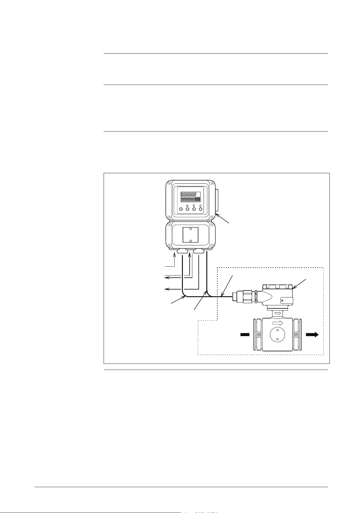
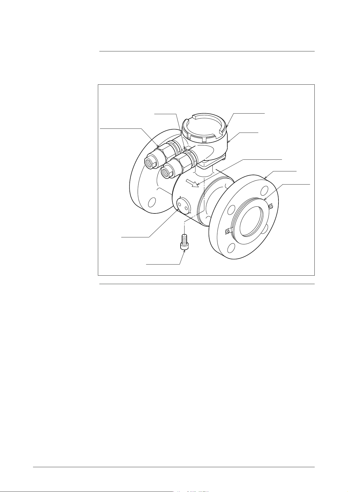
Figure 1-2 shows the structure of the detector and the names of the major
parts.
Figure 1-2 Details of the Detector
Grounding
terminal
Pressure-resistant
packing cable
adapter
(only for TIIS)
Terminal box
cover
Terminal
box
Flow direction
mark
Grounding
ring
Electrode
cover
Mounting screw
(4 places)
1 - 3
Continued on next page
Page 13
Detector Continued
Names and functions of parts
This table explains the major parts of the detector.
Name
Flow direction mark
Electrodes • The electrodes generate an electromotive force sig-
Electrode cover • Houses the electrodes. Do not remove the cover
Grounding ring • The electrode material varies according to the cor-
Terminal box • Houses the connection terminals used to apply a
Terminal box cover
(remote model only)
• Indicates the direction of fluid flow.
• Mount the detector so that the measured fluid flows
in the direction indicated by this mark.
nal proportional to the flow rate of the fluid passing
through the detector.
• The electrode material varies depending on the corrosion characteristics of the fluid to be measured.
with the detector installed on a pipe.
rosive characteristics of the fluid to be measured.
Also, the structure varies with the material.
standard voltage.
• Houses excitation and signal terminals.
• Keep the terminal box cover on during operation.
Function
Pressure-resistant Packing Cable Adapter
• Seals the cable terminal to assure and enhance explosion-proof capability, insulation resistance and
mechanical strength. Required for any explosionproof instrumentation.
Warning
• To prevent the gas or liquid in the pipe from escaping do not remove the electrode cover or the electrodes when the detector is
installed on a pipe.
1 - 4
Page 14
Detector Continued
Names of major
parts of the
flange type
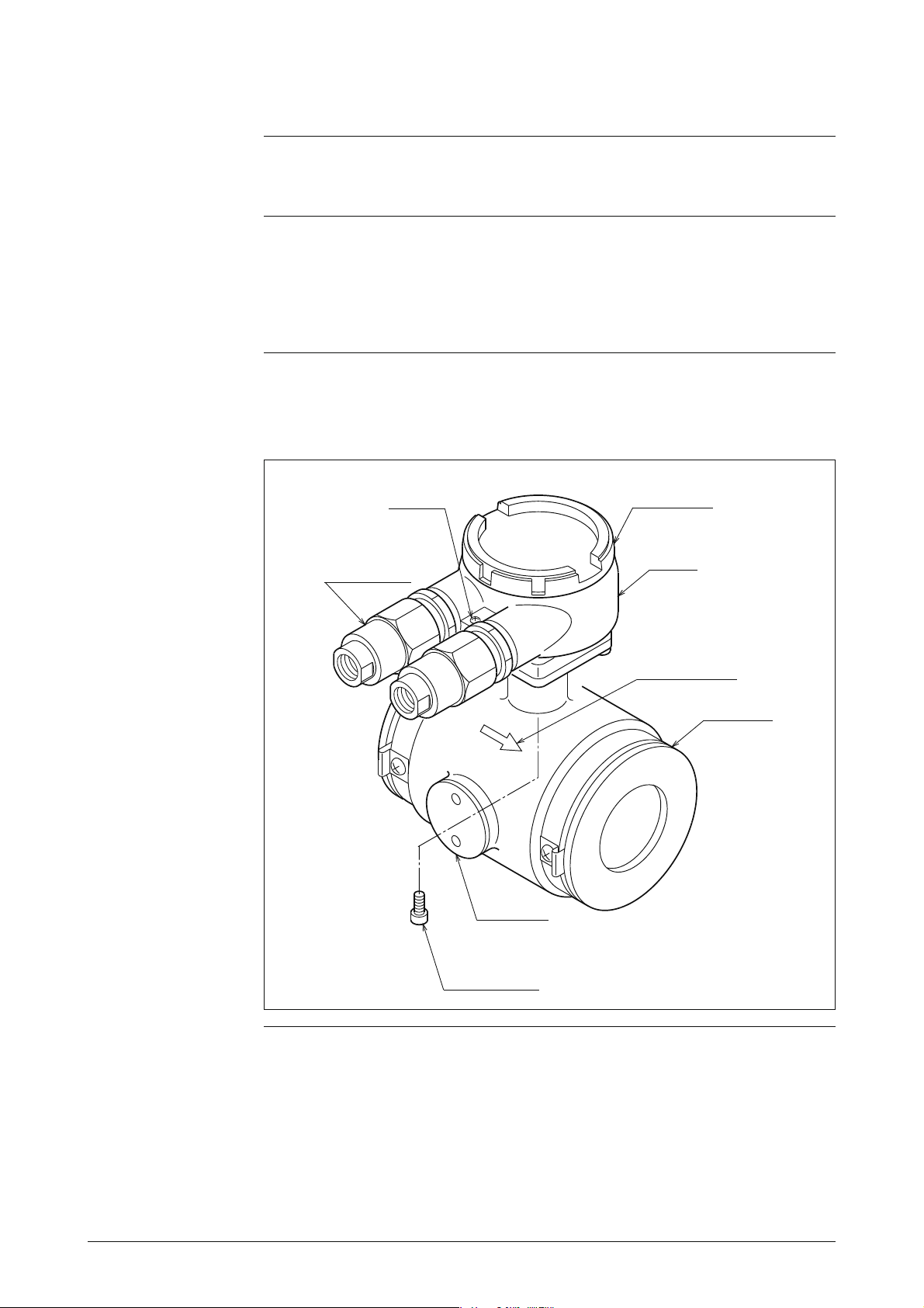
Figure 1-3shows the structure of the detector and the names of its major parts.
Figure 1-3 Details of the Flanged Detector
Pressure-resistant
packing cable
adapter
(only for TIIS)
Electrode
cover
Grounding
terminal
Terminal box
cover
Terminal
box
Flow direction
mark
Flange
Grounding
ring
Mounting screw
(4 places)
Continued on next page
1 - 5
Page 15

Detector Continued
Names and functions of parts
This table explains the major parts of the detector.
Name
Flow direction mark
Electrodes • The electrodes generate an electromotive force sig-
Electrode cover • Houses the electrodes. Do not remove the cover
Grounding ring • The electrode material varies according to the cor-
Terminal box • Houses the connection terminals used to apply a
Terminal box cover
(remote model only)
Pressure-resistant Packing Cable Adapter
• Indicates the direction of fluid flow.
• Mount the detector so that the measured fluid flows
in the direction indicated by this mark.
nal proportional to the flow rate of the fluid passing
through the detector.
• The electrode material varies depending on the corrosion characteristics of the fluid to be measured.
with the detector installed on a pipe.
rosive characteristics of the fluid to be measured.
Also, the structure varies with the material.
standard voltage.
• Houses excitation and signal terminals.
• Keep the terminal box cover on during operation.
• Seals the cable terminal to assure and enhance explosion-proof capability, insulation resistance and
mechanical strength. Required for any explosionproof instrumentation.
Function
Warning
• To prevent the gas or liquid in the pipe from escaping do not remove the electrode cover or the electrodes when the detector is
installed on a pipe.
1 - 6
Page 16
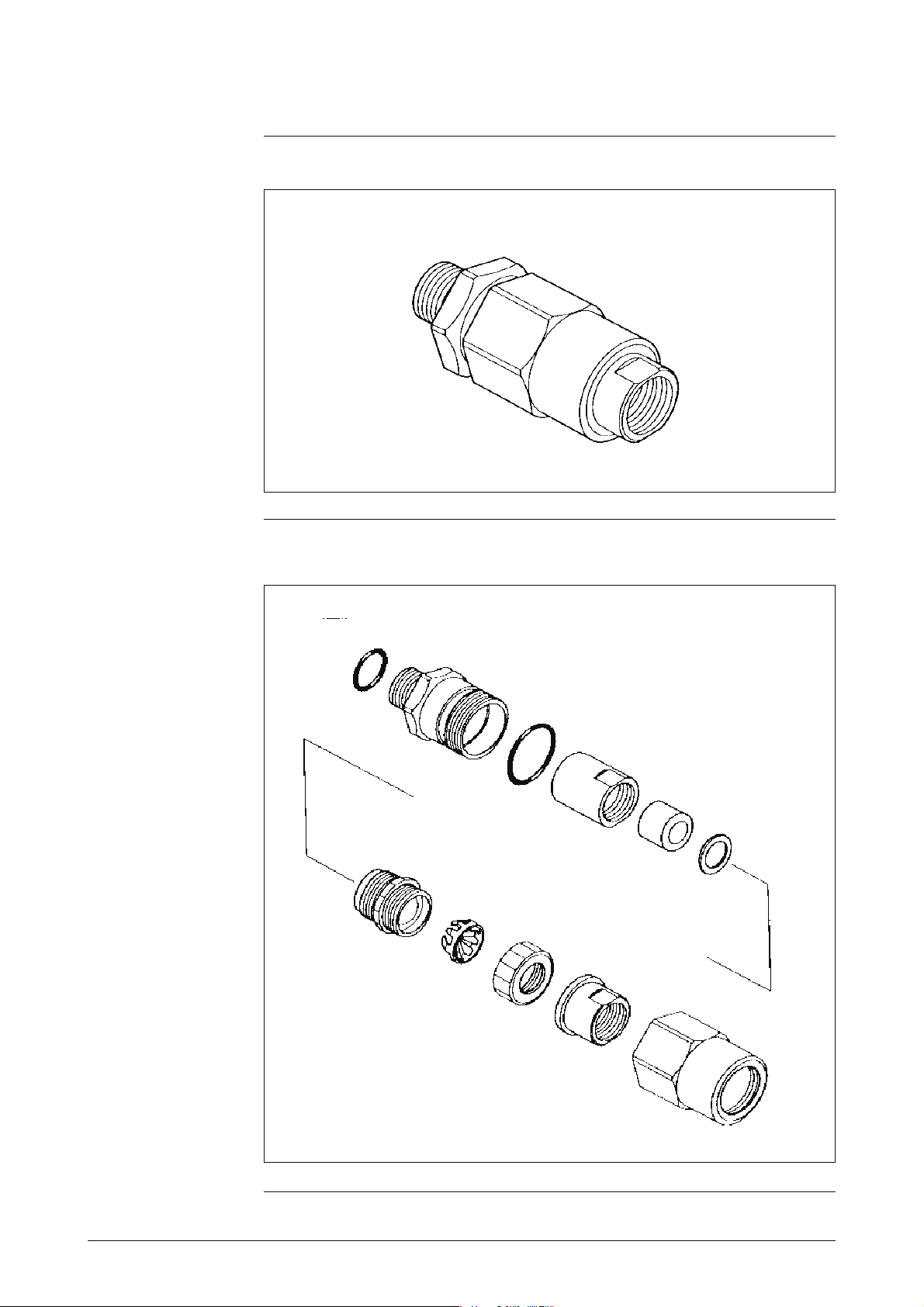
Figure 1-4 Cable adapter with flameproof packing
Figure 1-5 Details of the cable adapter with flameproof packing
1 - 7
Page 17
Detector Terminal Box
Names of parts
Names and
explanations of
parts
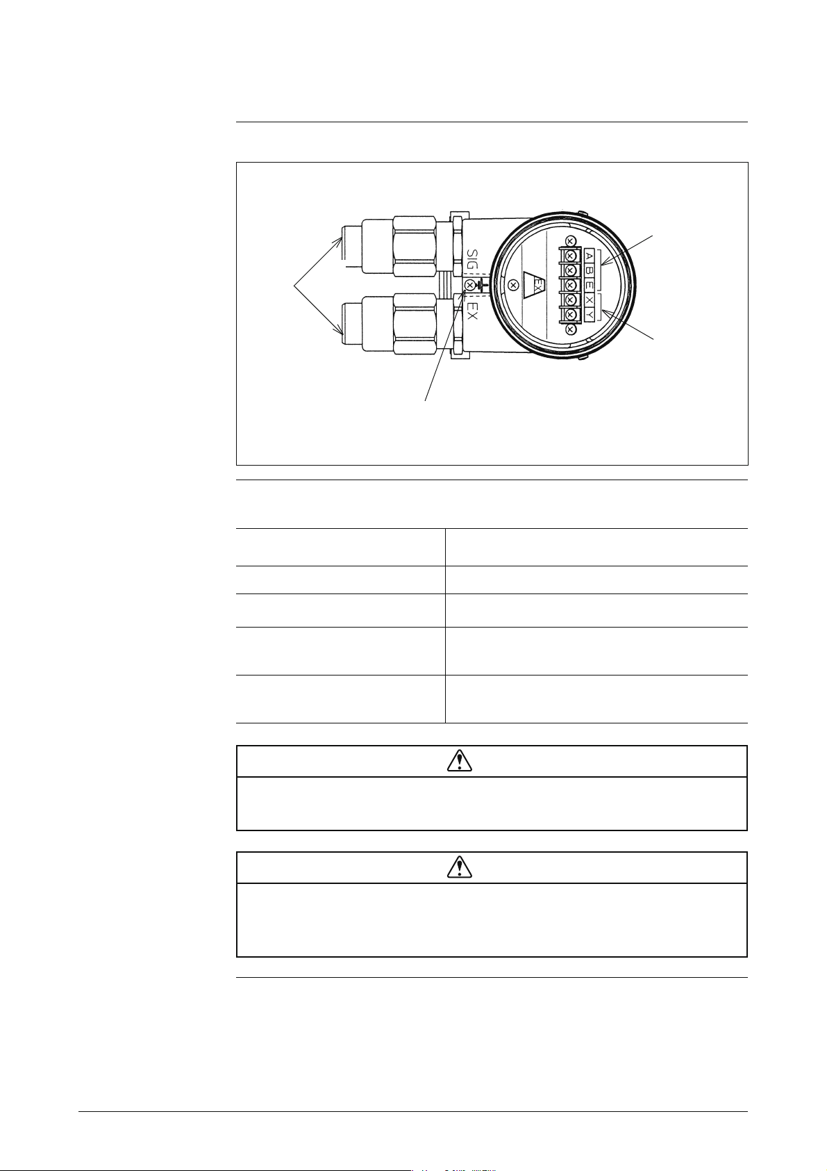
Figure 1-6 Detector Terminal Box
Signal
terminals
Conduit
wiring
connectors
Excitation
terminals
Grounding
terminal
The table below explains the major parts of the detector terminal box.
Name Explanation
Signal terminals
Excitation terminals
Conduit wiring connectors • The excitation cable and the signal cable are
Grounding terminal • This terminal is used to ground the detector
• These are marked A, B, and C.
• These are marked X and Y.
wired through these connectors.
(class 3 grounding).
Warning
• Turn off power to the converter side before wiring, to avoid electric
shock.
Caution
• Be sure to ground the detector without fail (class 3 grounding). In-
sufficient grounding could cause output fluctuation, instability of
the zero point, or output drift.
1 - 8
Page 18

1.3 Use of Explosion-proof Electromagnetic Flowmeters
for TIIS
Before use
Flameproof
structure
Location guidelines
This flowmeter is of flameproof structure. Read this item carefully to ensure
correct use.
Flameproof structure means a totally enclosed housing that is capable of withstanding an explosion of a gas or vapor within it, and of preventing the ignition of an explosive gas or vapor that may surround it.
Install the flowmeter in accordance with the following guidelines:
• The flowmeter can be installed in hazardous areas of grade:
IIC T4
1 2
1. Explosive gaseous atmosphere graded IIC
2. Gaseous atmosphere where the ignition temperature is 135°C or greater
This means that the flowmeter can only be installed in Class I and II
locations. It cannot be installed in Class 0 locations.
• When installing the flowmeter in a hazardous or non-hazardous area, refer
to the installation specifications described in the appendix for the correct
wiring.
• The pressure-resistant packing cable adapter must be placed in the signal
wire outlet of the flowmeter converter. Use the adapter supplied.
• Handle the flowmeter case and cover carefully to prevent any damage or
distortion. Properly tighten the converter cover and never open it during
operation.
The specified explosion capability cannot be guaranteed if any of the above
guidelines are ignored.
When wiring the flowmeter in a Class 1 Hazardous Area, or in any area where
only low voltage wiring work is allowed, follow procedures published by the
Research Institute of Industrial Safety.
1 - 9
Page 19
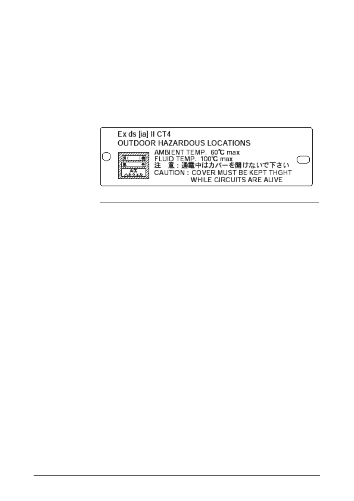
Nameplates
The flowmeter is required to pass a certified examination conducted in accordance with Industrial Safety and Hygiene Regulations. The Industry Safety
Engineering Association authorizes the flowmeter to carry a certified nameplate only after passing the examination.
Figure 1.6 Certified Nameplate
1 - 10
Page 20

1.4 Use of Explosion-proof Electromagnetic Flowmeters
for FM/CSA
Before use
Flameproof
(Explosionprotection)
structure
Location
guidelines
This flowmeter is of flame-proof (Explosion-protection) structure. Read this
item carefully to ensure correct use.
Flameproof structure means a totally enclosed housing that is capable of withstanding an explosion of a gas or vapor within it, and of preventing the ignition of an explosive gas or vapor that may surround it.
Install the flowmeter in accordance with the following guidelines:
1. FM/CSA
FM/CSA Explosion-proof model
THIS EQUIPMENT IS SUITABLE FOR USE IN CLASS I, II, III,
DIVISION 1, GROUPS (B, C, D, E, F, G).
CAUTION:
(1) power supply and internal voltage of ordinary equipment to the earth shall
not exceed AC250V 50/60HZ, DC250V in case of normal /formal condi-
tions.
(2) ambient temperature is from –10 to 60°C
(3) Process temperature is from –40 to 160°C
Continued on next page
1 - 11
Page 21
If an MGG18/19 detector is used with an MGG14C converter as an FM-approved nonincendive
product, both the detector and the converter should be FM-approved nonincendive products.
If they are not, the MGG18/19 detector cannot be used as an FM-approved nonincendive product.
1 - 12
Page 22

Chapter 2 - Installing the Device
Introduction
This section describes the installation and wiring of Electromagnetic
Flowmeter.
The required parts and method for installing this device may vary slightly
depending on the material of the wetting ring and the pipe.
Installation is explained in the following order:
• Criteria for selecting the installation environment
• An outline of the method of installing the device
• Detailed methods of installation depending on the material
2 - 1
Page 23
2-1 Before Installing
Criteria for Selecting the Installation Site (1)
Introduction
Environment
In order to make full use of the functions of the device, select an optimal
installation site by following the selection criteria below.
Caution
• Install the unit in a location with an ambient temperature of –25 to
+60°C and a relative humidity of 5% to 100%. Failing to meet
these requirements could cause output errors.
• Install the unit away from high-current power lines, motors and
transformers to prevent damage from electromagnetic induction.
Failing to meet this requirement could cause output errors.
• Do not install the unit in a location subject to severe vibration or a
highly corrosive atmosphere. Failing to meet this requirement
could break the neck of the detector or cause other damage.
• As far as possible, install the unit out of direct sunlight. Failing to
meet this requirement could cause output errors.
Fluid to be
measured
Caution
The location for your MagneW FLEX+/PLUS+ must satisfy the
following conditions. Failing to meet these requirements could
cause output errors and fluctuations.
• A location where the conductance of the fluid to be measured
matches the stated specification (specs. vary according to the converter used) and is more or less constant.
• A location where the fluid to be measured can be regarded as electrochemically uniform. For example, if two fluids are mixed at an
upstream point, the two fluids should be uniformly mixed by the
time they reach the measurement point.
• A location where the distribution of suspended matter, if any, can
be regarded as nearly uniform
Continued on next page
2 - 2
Page 24

Criteria for Selecting the Installation Site (1) Continued
Fluid to be
measured
(continued)
• The fluids listed below could cause measurement trouble. Do not
use this device, therefore, even if their conductance, temperature,
and pressure fall within the specifications of the device (see Appendix A, "Device Standard Specifications and Model Numbers.")
(1) Fluids that have sufficient conductance at high temperatures
but do not satisfy the conductance requirements at room temperature (about 20°C) (Examples: fatty acids and soap)
(2) Certain fluids that contain surfactants (Examples: rinses,
shampoos, and CWM)
(3) Conductive adherents (Example: deposition of rosin + con-
ductive material)
(4) Insulating adherents (Examples: oil, kaolinite, kaolin, and cal-
cium stearate)
Caution
Precautions to
observe after
installing
Caution
(1) After installing this unit, do not use it as a foothold as this can
damage the unit.
(2) With the integrated detector, be careful not to break the glass in
the detector window.
Warning
(1) When removing this unit, make sure there is no residual liquid
or pressure inside the piping and the detector. Any residual
liquid or pressure can cause injury.
2 - 3
Page 25

Criteria for Selecting the Installation Site (2)
Detector position
• Position the detector so that its internal detector passage is continuously
filled with the fluid being measured. Figure 2-1 shows examples of positions that fulfill this condition.
Figure 2-1 Proper Placement of the Detector
Air is easily traped.
May not fill
with fluid.
May not fill
with fluid
Bad
Good
Pump
Good
Caution
• Fill the pipe with liquid and install the detector in a location that
satisfies the conditions circled above. If the pipe is not filled it can
cause an output error.
• When the fluid to be measured is of high viscosity, connecting the detector
to a vertical pipe is recommended (in order to secure an axial symmetrical
flow). The fluid must flow from the top down.
• Install a straight pipe section between the upstream and downstream positions. For the length of the straight pipe section, refer to the figure below.
Figure 2-2 Straight Pipe Section on the Upstream Side of the Detector (D:
nominal bore diameter of the detector)
Upstream
Right-angle joint
Greater than 5D
T-joint
Greater than 5D
Gate valve (completely open)
Detector
Greater than 5D
Diffuser with cone angle greater
than 15°
Detector
(if 15° or less, considered as
straight-pipe section)
Concentrater
(considered as straight-pipe
Detector
section)
Greater than 5D
Greater than 5D
Any type of valve
Greater than 10D
Detector
Detector
Detector
Continued on next page
2 - 4
Page 26

Criteria for Selecting the Installation Site (2) Continued
Detector position
(continued)
• Although a pipe section is not necessary on the downstream side, secure a section of at least 2D if drift current or similar is likely.
• Select a place where there is no major pulse flow. (Install the detector
in a location distant from a pump.)
• Secure the space required for inspection of the terminal box.
Figure 2-3 Space Allowance for Inspections
2 - 5
Page 27

Directions of the Terminal Box and the Converter
Introduction
Repositioning the
terminal box or
converter
In some locations, the direction of the terminal box or the converter may be
unsuitable if the detector is installed as it is shipped. In such a case, the terminal box or the converter can be repositioned.
After selecting a installation site, adjust the direction of the terminal box or
the converter in advance by the two methods shown below.
The terminal box or the converter can be repositioned at right angles. Follow
the procedure below.
Step Procedure
1
2
Using an M5 hex wrench, remove the four screws securing the
terminal box or converter.
Holding the detector, rotate the terminal box or converter horizontally to the desired position.
Caution
• Do not rotate the unit more than 180° (one half rotation). Any greater rotation can break wiring
parts.
• If the terminal box or converter is removed, make
sure that the O-ring, which provides an air-tight
seal, is still fitted into the O-ring groove.
3 Using a hex wrench, re-tighten the four screws to secure the termi-
nal box or converter.
Continued on next page
2 - 6
Page 28

Directions of the Terminal Box and the Converter Continued
Repositioning
the terminal
box or converter
(continued)
Figure 2-4 Repositioning the Terminal Box or Converter
Hex wrench
Caution
• After removing the screws, do not pull hard on the terminal box or
converter. Otherwise, the lead wire inside can break.
2 - 7
Page 29

2-2 Method of Installation
2-2-1 Installing a Wafer Detector
Basic Installation Method
Introduction
Installation example
The device can installed as a wafer, flange, union, hose, or clamp unit. Referring to the appropriate method of installation, install the unit properly.
Figure 2-5 shows the basic method for installing the device.
Figure 2-5 Device Installation Example
Nuts (optional)
Through-bolts (optional)
Pipe
Gasket (required in case of
Centering nuts
(supplied)
SUS material
grounding rings. In
other cases, a gasket
is supplied.)
Caution
• Be careful in handling this unit. It is heavy, dropping it accidentally
could cause injury.
Continued on next page
2 - 8
Page 30

Basic Installation Method Continued
Fastening torque
Flange shape
Caution
• Table 2-1 shows the fastening torque for each pipe bore. Using
centering hardware, apply the prescribed fastening torque to prevent any liquid leak from the pipe.
Table 2-1 Fastening Torque Levels
Nominal Detector Bore Fastening Torque
2.5 - 15A 13-18N•m (130-180kgf•cm)
25A 20-30N•m (200-300kgf•cm)
40A 50A 65A 80A 30-50N•m (300-500kgf•cm)
100A 50-70N•m (500-700kgf•cm)
125A 150A 80-100N•m (800-1000kgf•cm)
200A 90-100N•m (900-1000kgf•cm)
The flanges used should be such that the area of contact with the gasket is
maximized, as shown in Figure 2-6.
Figure 2-6 Flange Shape
Acceptable
Flange
Welding
Pipe
Welding
Unacceptable
(The liquid
could leak
because of
the small
area of
contact with
the gasket.)
Caution
• Before installing the detector be sure to flush out any foreign matter that may be present in interior passage of the detector. Residual foreign matter could cause output fluctuations.
• Do not touch the electrodes or allow oil or fat to come into contact
with them. It could cause output fluctuations.
• Align the flow direction mark on the detector with the direction of
the liquid flow. Misalignment could result in a negative output.
2 - 9
Continued on next page
Page 31

Basic Installation Method Continued
Flange shape
(continued)
Warning
• Before installing the detector make sure that the pipe is exactly
straight and centered. Any irregularity in these respects could
cause leakage or other hazards.
Figure 2-7 Examples of Unacceptable Installations (1)
Tilted pipe Off center Off center
Caution
• Never force the device between two flanges when the space is too
narrow. It can damage the unit.
Figure 2-8 Example of Unacceptable Installation (2)
Warning
• Ensure the bore diameters of the pipe and the detector are exactly
the same, install the detector so that the gasket does not protrude
into the inner bore of the pipe, as this could result in leakage or
other hazards.
Caution
• Tighten each bolt a little at a time and apply uniform pressure to all
the bolts while fastening them. If leakage does not stop on completion of fastening, make sure that the pipe is not off center, then
tighten the bolts little by little. Install the detector carefully so that
the fastening torque does not exceed the prescribed limit; otherwise the unit could be damaged.
2 - 10
Page 32

Parts Necessary for Installation
Introduction
Centering nuts
The following parts are necessary for the installation of the detector:
• Centering nuts (four supplied)
• Connecting bolts and nuts (available separately)
• Gaskets: Required when using grounding rings made of SUS material.
Not required when using grounding rings made of hastelloy, titanium, tantallum, or platinum.
• Protective plate: Required when connecting the detector to polyvinyl chlo-
ride (PVC) piping.
To install the detector, use centering nuts to ensure the exact alignment of
the pipe and the detector.
Slip the centering bolts onto the through-bolts, and set the detector on top of
the nuts so that the nuts are on four sides of the detector.
The positions of the centering nuts depend on the direction in which the
detector is installed.
For the positions of the centering nuts, refer to Figures 2-9 and 2-10.
Figure 2-9 Horizontal Centering of the Detector (Position two centering
nuts against each flange.)
Flange
Position of a
centering nut
Figure 2-10 Vertical Centering of the Detector (Position the four center-
ing nuts on the bottom flange.)
Flange
Position of a
centering nut
2 - 11
Continued on next page
Page 33

Parts Necessary for Installation Continued
Gaskets
Gaskets are supplied with the grounding ring, except when it is made of SUS
material. Secure gaskets when you use a grounding ring made of SUS mate-
rial. We recommend gasket material such as joint sheet or PTFE. For the bore
diameters of the gaskets, refer to Table 2-2. We do not recommend the use of
rubber gaskets. Observe the precautions below.
Caution
• Too small a gasket diameter may affect the flow velocity distribution resulting in inaccurate measurements.
• Too large a gasket diameter may cause leakage. Also, any solid
substance in the fluid to be measured could accumulate between
the gasket and the flange, resulting in inaccurate measurements.
Table 2-2 Recommended Inner Diameters of Gaskets
Bore
2.5A 5A 10A 15A 25A 40A 50A 65A 80A 100A 125A 150A 200A
dia.
Dimensions
Inner
diameter
6.5 6.5 11.5 16.5 25.5 40.5 52 65 79 104 127 151 200
±1 ±1 ±1 ±1 ±1 ±1 ±1 ±1 ±1 ±1 ±1 ±1 ±1
(Unit: mm)
If you install the detector at a lower torque level using rubber gaskets, you
must use gaskets with the bore and outside diameters shown in Table 2-5 for
the respective pipe bore. Depending on the grounding ring material, two gaskets of different thicknesses may be required. (See Figure 2-16 on page 2-23
and Figure 2-19 on page 2-25.)
Table 2-3 Inner and Outside Diameters of Rubber Gaskets (0.5 to 1 mm
Bore
dia.
Dimensions
Inner
diameter
Outside
diameter
thick)
2.5A 5A 10A 15A 25A 40A 50A 65A 80A 100A 125A 150A 200A
6.5 6.5 11.5 16.5 25.5 40.5 52 65 79 104 127 151 200
±1 ±1 ±1 ±1 ±1 ±1 ±1 ±1 ±1 ±1 ±1 ±1 ±1
34 34 34 34 50 75 91 111 121 146 177 207 257
±1 ±1 ±1 ±1 ±1 ±1 ±1 ±1 ±1 ±1 ±1 ±1 ±1
(Unit: mm)
Table 2-4 Inner and Outside Diameters of Rubber Gaskets (3 to 4 mm thick)
(Unit: mm)
Bore
dia.
Dimensions
Inner
diameter
Outside
diameter
2.5A 5A 10A 15A 25A 40A 50A 65A 80A 100A 125A 150A 200A
6.5 6.5 11.5 16.5 25.5 40.5 52 65 79 104 127 151 200
±1 ±1 ±1 ±1 ±1 ±1 ±1 ±1 ±1 ±1 ±1 ±1 ±1
34 34 34 34 50 68 84 104 114 139 166 190 240
2 - 12
Page 34

Selecting an Installation Method
• The necessary materials and the installation method vary according to the material of the ring and that of the pipe on which the
detector is to be installed. Select the appropriate method of installation after confirming the specifications of the detector to be installed and the conditions of installation. Improper installation may
result in leakage or damage to the pipe flanges.
Caution
Installation method
according to
materials
Select the appropriate installation method from the table below.
Pipe material Grounding Ring Material See Page
Metal
PVC
SUS material 2-18
Non-SUS material 2-19
SUS material 2-21
Non-SUS material 2-24
2 - 13
Page 35

Installation on Horizontal Pipe
• Improper installation may result in leakage or damage to the pipe
flanges.
Caution
Parts required
Procedure
The following parts are required:
• Through-bolts and nuts
• Centering nuts
• Gaskets: The required gasket material will vary according to the material of
the pipe on which the detector is to be installed. See the installation procedures for different pipe materials described on pages 218 to 2-25.
Follow this procedure to install the detector on a horizontal pipe.
Step Action Drawing
1
Insert through-bolts in the
flange holes shown by black
dots in the drawing. Slip two
centering nuts onto each
through-bolt before inserting the
bolts.
Flange
2
• Turn the detector so that the
direction mark on the detector
matches the direction of fluid
flow.
• Insert the detector and gaskets between the pipe
flanges.
• Position the detector so that it
sits on top of the centering.
Gasket
Direction of
fluid flow
Continued on next page
2 - 14
Page 36

Installation on Horizontal Pipe Continued
Procedure
(continued)
Step Action Drawing
3
• Make sure that the detector remains properly centered.
• Make sure that the gaskets do
not protrude beyond the edges
of the pipe flanges.
• When you have checked these
items, insert the remaining
through-bolts into the flange
holes and tighten the bolts
evenly using the appropriate
fastening torque given on
page 2-8.
2 - 15
Page 37

Installation on Vertical Pipe
• Improper installation may result in leakage or damage to the pipe
flanges.
Caution
Parts required
Procedure
The following parts are required:
• Through-bolts and nuts
• Centering nuts
• Gaskets: The required gasket material will vary according to the material of
the pipe on which the detector is to be installed. See the installation procedures for different pipe materials described on pages 218 to 2-25.
Follow this procedure to install the detector on a horizontal pipe.
Step Action Drawing
1
Of the flange holes shown by
black dots in the drawing, insert
through-bolts into the two holes
at the back and fasten them
lightly with nuts. Slip one centering nut onto each through
bolt before inserting the bolts.
Flange
Terminal
box side
Back
Centering nuts
2
• Turn the detector so that the
direction mark on the detector
matches the direction of fluid
flow.
• Insert the detector and gaskets between the pipe
flanges.
Direction of fluid
flow
Gaskets
Continued on next page
2 - 16
Page 38

Installation on Vertical Pipe Continued
Procedure
(continued)
Step Action Drawing
3
4 • Make sure that the detector re-
Insert through-bolts fitted with
one centering nut each into the
remaining two flange holes
shown by black dots in Steps 1
and 2.
mains properly centered.
• Make sure that the gaskets do
not protrude beyond the edges
of the pipe flanges.
• When you have checked these
items, insert the remaining
through-bolts into the flange
holes and tighten the bolts
evenly using the appropriate
fastening torque given on page
2-9.
2 - 17
Page 39

Installation on Metal Pipe (1)
Introduction
Required parts
Installation
procedure
The installation method described in this section corresponds to the following
combination of pipe and grounding ring materials. For the installation
method corresponding to any other combination, refer to the table on page
2-13.
Pipe material: Metal
Grounding ring material: SUS material
The following parts are required:
• Through-bolts and nuts
• Centering nuts
• Gaskets: We recommend non-rubber gaskets such as those made of joint
sheet or PTFE.
For recommended bore diameters, refer to Table 2-2 on page 2-
12. Although rubber gaskets may be used, it is not possible to
reduce the fastening torque.
• Install the detector as shown in Figure 2-11. The torque level for tightening
the bolts is not related to the gasket material. See Table 2-1 on page 2-9 for
the appropriate torque. For the inner diameter of the gaskets, see Table 2-2
on page 2-12.
• To use rubber gaskets for a low fastening torque, refer to page 2-23.
Caution
• Please note that the use of rubber gaskets and a lower fastening
torque may result in insufficient surface pressure between the lining and the grounding ring, resulting in leakage.
Figure 2-11 Installation Using SUS Material Grounding Ring and Metal
Pipe
Pipe side flange
Lining
Grounding ring
Gasket
2 - 18
Page 40

Installation on Metal Pipe (2)
Introduction
Required parts
The installation method described in this section corresponds to the following
combination of pipe and grounding ring materials. For the installation
method corresponding to any other combination, refer to the table on page
2-13.
Pipe material: metal
Grounding ring material: other than SUS material
The following parts are required. No gaskets are necessary since PTFE gaskets are provided.
• Through-bolts and nuts
• Centering nuts
Continued on next page
2 - 19
Page 41

Installation on Metal Pipe (2) Continued
Installation
procedure
• Install the detector as shown in Figure 2-12. See Table 2-1 on page 2-9 for
the appropriate fastening torque.
• To use rubber gaskets for a low fastening torque, refer to page 2-25.
Caution
• Please note that the use of an additional gasket besides the existing PTFE gasket may result in leakage (see Figure 2-13).
Figure 2-12 Installation Using Non-SUS Material Grounding Ring and
Metal Pipe
PTFE gasket
Lining
Grounding ring
Figure 2-13 Example of Incorrect Installation
PTFE gasket
Lining
Grounding ring
Gasket
2 - 20
Page 42

Installation on PVC Pipe (1)
Introduction
Required parts
The installation method described in this section corresponds to the following
combination of pipe and grounding ring materials. For the installation
method corresponding to any other combination, refer to the table on page
2-13.
Pipe material: PVC
Grounding ring material: SUS material
The following parts are required:
• Through-bolts and nuts
• Centering nuts
• Gaskets: Non-rubber gaskets are recommended (i.e. joint sheet or PTFE).
See Table 2-2 on page 2-12 for the recommended bore diameters. When
using rubber gaskets, another gasket of the same material and with a thickness of 0.5 to 1.0 mm is required. See Table 2-3 on page 2-12 for the
appropriated dimensions.
• Protective plate: Use the protective plate if bolt tightening at the specified
torque threatens to warp or damage the PVC pipe. See Figure 2-15 for an
illustration of the protective plate.
Continued on next page
2 - 21
Page 43

Installation on PVC Pipe (1) Continued
Installation
procedure
The installation procedure varies with such conditions as the fastening torque
and the need for a protective plate. Choose one of the following three methods as applicable.
1. Use this method to install the detector with a specified fastening torque.
Install the detector as shown in Figure 2-14. The torque level for tightening the bolts is not related to the gasket material. See Table 2-1 on page 29 for the appropriate torque. For the inner diameter of the gaskets, see
Table 2-2 on page 2-12.
Caution
• Please note that the use of rubber gaskets and a lower fastening
torque may result in insufficient surface pressure between the lining and the grounding ring, resulting in leakage.
Figure 2-14 Installation Using SUS Material Grounding Ring
Lining
Gasket
Grounding ring
Continued on next page
2 - 22
Page 44

Installation on PVC Pipe (1) Continued
Installation
procedure
(continued)
2. Use this method to install the detector using a protective plate to prevent
the PVC pipe from being deformed or damaged when the bolts are tightened with the specified torque.
Install the protective plate between the outer side of the PVC flange and
the detector, as shown in Figure 2-15. The protective plate protects the
PVC pipe from deformation or damage when secured at the specified
torque. The torque level is unrelated to the pipe or grounding ring material. See Table 2-1 on page 2-9 for the appropriate torque.
Figure 2-15 Installation Using SUS Material Grounding Ring (with protec-
tive plate)
Protective plate
Gasket
Lining
Grounding ring
3. Use this method to install the detector using a low fastening torque and
rubber gaskets.
Remove the grounding ring from the detector, insert a rubber gasket 0.5 to
1.0 mm thick, then reinsert the grounding ring on top of the rubber gasket.
With the rubber gasket in the position shown in Figure 2-16, attach the
detector to the pipe. Fasten the bolts with a torque that provides a leakproof joint. In this case, use the two kinds of rubber gaskets made of the
same material.
Figure 2-16 Installation Using SUS Material Grounding Ring (with rubber
gasket)
Lining
Rubber gasket
(0.5-1mm)
2 - 23
Rubber gasket
(3-4mm)
Grounding ring
Page 45

Installation on PVC Pipe (2)
Introduction
Required parts
The installation method described in this section corresponds to the following
combination of pipe and grounding ring materials. For the installation
method corresponding to any other combination, refer to the table on page
2-13.
Pipe material: PVC
Grounding ring material: Other than SUS material
The following parts are required:
• Through-bolts and nuts
• Centering nuts
• Gaskets: No gaskets are necessary due to the provision of a PTFE gasket.
When using a rubber gasket, gaskets of the same material and
of two thicknesses, 0.5 to 1.0 mm and 3.0 to 4.0 mm, are required. See Table 2-3 and 2-4 on pages 2-12 for the appropriate
dimensions.
• Protective plate: A protective plate is required if tightening the bolts to
the specified torque may deform or damage the PVC
pipe. Use stainless steel or similar hard metal 1 mm
thick or over. For the shape, see Figure 2-18.
Installation
procedure
The installation procedure varies with such conditions as the fastening torque
and the need for a protective plate. Choose one of the following three methods as applicable.
1. Use this method to install the detector with the specified fastening torque.
Install the detector as shown in Figure 2-17. See Table 2-1 on page 2-9 for
the appropriate fastening torque.
Figure 2-17 Installation Using the Grounding Ring of Non-SUS Material
PTFE gasket (supplied)
Lining
Grounding ring
2 - 24
Continued on next page
Page 46

Installation on PVC Pipe (2) Continued
Installation
procedure
(continued)
2. Use this method to install the detector along with a protective plate to
prevent PVC pipe from being deformed or damaged when the bolts are
tightened to the specified torque.
Insert a protective plate between the outer side of the PVC flange and the
detector as shown in Figure 2-18. The protective plate protects the PVC
pipe from deformation or damage when it is secured to the specified
torque. For the appropriate torque, see Table 2-1 on page 2-9.
Figure 2-18 Installation Using the Grounding Ring of Non-SUS Material
(with protective plate)
Protective plate
PTFE gasket
Lining
Grounding ring
(supplied)
3. Use this method to install the detector using a low fastening torque and
rubber gaskets
First, remove the grounding ring from the detector, then insert a rubber
gasket with a thickness of 0.5 to 1.0 mm. Then reinsert the grounding ring
on top of the rubber gasket.
Next, remove the PTFE gasket and insert a rubber gasket 3.0 to 4.0 mm
thick to replace it. Under these conditions, install the detector on the pipe
as shown in Figure 2-19. Tighten the bolts to the torque required to
achieve a fluid seal for the rubber gasket. In this case, the two kinds of
rubber gaskets that are used should be made of the same material. For the
dimensions of the rubber gaskets, refer to Table 2-3 and Table 2-4 on page
2-12.
Figure 2-19 Installation Using the Grounding Ring of Non-SUS Material
(with rubber gasket)
Lining
Rubber gasket
(0.5-1mm)
2 - 25
Rubber gasket (3-4mm)
Grounding ring
Page 47

2-2-2 Installing a Flanged Detector
Basic Installation Method
Installation example
Figure 2-20 shows the basic method for installing the device.
Figure 2-20 Installation Example
Nuts
Bolts
Pipe
Gasket (Required when the
grounding ring is
made of SUS
material. In other
cases, the gasket is
supplied.)
Fastening torque
Caution
• Be careful in handling flanged detectors. Dropping it could cause
injury.
Warning
• Table 2-5 shows the fastening torque for each pipe bore. Apply the
prescribed fastening torque to prevent leakage.
Continued on next page
2 - 26
Page 48

Basic Installation Method Continued
Fastening torque
(continued)
Table 2-5 Fastening Torque (1)
Bore and Flange Ratings Fastening Torque
N•m (kgf•cm)
2.5-15mm JIS10K 6-9 (82-132)
JIS20K 6-9 (82-132)
JIS30K 18-31 (184-316)
ANSI150 6-9 (82-132)
ANSI300 6-9 (82-132)
DIN10/16 6-9 (82-132)
DIN25/40 9-14 (92-143)
25mm JIS10K 21-31 (214-316)
JIS20K 21-32 (214-326)
JIS30K 23-36 (234-367)
ANSI150 11-17 (112-173)
ANSI300 22-34 (224-347)
DIN10/16 10-14 (102-143)
DIN25/40 12-18 (122-184)
40mm JIS10K 22-32 (224-326)
JIS20K 22-34 (224-347)
JIS30K 41-65 (418-663)
ANSI150 13-18 (132-184)
ANSI300 36-57 (367-581)
DIN10/16 22-32 (224-326)
DIN25/40 25-38 (255-388)
50/65mm JIS10K 24-34 (245-347)
JIS20K 19-31 (194-316)
JIS30K 22-34 (224-347)
ANSI150 23-32 (235-326)
ANSI300 20-32 (204-326)
DIN10/16 24-34 (245-347)
DIN25/40 28-42 (286-428)
80mm JIS10K 20-31 (204-316)
JIS20K 37-61 (377-622)
JIS30K 42-66 (428-673)
JIS G3451 F12 18-37 (184-377)
ANSI150 26-35 (265-357)
ANSI300 37-57 (377-581)
DIN10/16 20-31 (204-316)
DIN25/40 25-39 (255-398)
2 - 27
Continued on next page
Page 49

Basic Installation Method Continued
Fastening torque
(continued)
Table 2-5 Fastening Torque (2)
Bore and Flange Ratings Fastening Torque
N•m (kgf•cm)
100mm JIS10K 22-33 (224-337)
JIS20K 41-66 (418-673)
JIS30K 61-95 (622-969)
ANSI150 21-31 (214-316)
ANSI300 43-66 (439-673)
DIN10/16 22-33 (224-337)
DIN25/40 48-74 (490-755)
125mm JIS10K 47-67 (479-683)
/150mm JIS20K 58-91 (592-928)
JIS30K 80-123 (816-1254)
ANSI150 42-60 (428-612)
ANSI300 50-74 (510-755)
DIN10/16 47-67 (479-683)
DIN25/40 97-145 (989-1479)
200mm JIS10K 44-65 (449-663)
JIS20K 66-102 (673-1040)
JIS30K 94-142 (959-1448)
ANSI150 42-59 (428-602)
ANSI300 81-120 (826-1224)
DIN10/16 47-68 (479-694)
DIN25/40 123-189 (1255-1928)
250mm JIS10K 51-63 (520-643)
JIS20K 81-99 (826-1010)
ANSI150 69-85 (704-867)
ANSI300 82-97 (840-990)
DIN10/16 57-69 (581-704)
DIN25 108-127 (1100-1300)
2 - 28
Continued on next page
Page 50

Basic Installation Method Continued
Fastening torque
(continued)
Table 2-5 Fastening Torque (3)
Bore and Flange Ratings Fastening Torque
N•m (kgf•cm)
300mm JIS10K 50-62 (510-632)
JIS20K 79-97 (806-989)
ANSI150 56-68 (592-694)
ANSI300 116-136 (1180-1390)
DIN10/16 45-55 (459-561)
DIN25 105-122 (1070-1250)
350mm JIS10K 54-66 (551-673)
JIS20K 143-167 (1460-1710)
ANSI150 80-98 (816-1000)
ANSI300 116-136 (1180-1390)
DIN10/16 42-52 (428-530)
DIN25 160-189 (1640-1930)
400mm JIS10K 72-88 (734-898)
JIS20K 160-189 (1640-1930)
ANSI150 80-98 (816-1000)
ANSI300 166-195 (1690-1990)
DIN10/16 72-88 (734-898)
DIN25 199-234 (2030-2390)
Continued on next page
2 - 29
Page 51

Basic Installation Method Continued
Flange shape
Use flanges that will maximize the area of contact with the gasket, as shown in
Figure 2-21.
Figure 2-21 Flange Shape
Acceptable Unacceptable
(The liquid
could leak out
because of the
Welding
Flange
Pipe
small area of
contact with the
gasket.)
Caution
• Before installing the detector, make sure any foreign matter is
flushed from the interior passage of the detector. Residual foreign
matter could cause output fluctuations.
• Do not touch the electrodes or allow oil or fat to come into contact
with them. This could cause output fluctuations.
• Align the flow direction mark on the detector in the direction of the
liquid flow. Misalignment could result in a negative output.
Continued on next page
2 - 30
Page 52

Basic Installation Method Continued
Flange shape
(continued)
Caution
• Never force the device between two flanges when the space is too
narrow.
Figure 2-22 Example of Incorrect Mounting
Warning
• After ensuring that the bore diameter of the pipe and that of the
detector are the exactly the same, install the detector so that the
gasket does not protrude into the inner bore of the pipe. Failing to
do so could result in leakage or other hazards.
Caution
• Tighten each bolt a little at a time, apply uniform pressure to all the
bolts while fastening them. If leakage does not stop on completion
of fastening, make sure that the pipe is not off center, then tighten
the bolts little by little. Install the detector carefully so that the fastening torque does not exceed the prescribed limit. Otherwise, the
unit could be damaged.
2 - 31
Page 53

Parts Necessary for Installation
Introduction
Gaskets
The following Parts are necessary for the installation of the device:
• Gaskets: Gaskets are required when using grounding rings made of SUS
material. Gaskets are supplied when using grounding rings made
of other material.
Gaskets are supplied with the grounding ring, except when it is made of SUS
material. Supply the gaskets when you use a grounding ring made of SUS
material. We recommend a non-rubber gasket material such as joint sheet or
PTFE.
For the bore diameters of the gaskets, refer to Table 2-6.
Caution
• Too small a gasket diameter may affect the flow velocity distribution, resulting in inaccurate measurements.
• Too large a gasket diameter may cause leakage. Also, if there are
any solids in the fluid to be measured, these may build up between
the gasket and the flange, resulting in inaccurate measurements.
Table 2-6 Recommended Inner Diameters of Gaskets
Bore diameter (mm) Inner diameter (mm)
2.5 11±1
511±1
10 11±1
15 16±1
25 25±1
40 40±1
50 51±1
65 64±1
80 76±1
100 101±1
125 124±1
150 148±1
200 196±1
250 246±1
300 296±1
350 346±1
400 396±1
2 - 32
Page 54

Selecting an Installation Method
Caution
Installation method
according to
material
Caution
• The necessary materials and the method of installation vary depending on the material of the grounding ring and the material. Select the applicable method of installation after checking the specifications of the detector to be installed and the conditions of installation. Improper installation may result in leakage or damage to the
pipe flanges.
Select the appropriate installation method from the table below.
Pipe material Grounding Ring Material See Page
Metal SUS material 2-34
Other than SUS material 2-35
PVC SUS material 2-37
Other than SUS material 2-38
2 - 33
Page 55

Installation on Metal Pipe (1)
Introduction
Required parts
Installation
procedure
The installation method described in this section is to be used with the following grounding ring material. For the installation method used for any other
grounding ring material, refer to the table on page 2-35.
Pipe material: Metal
Ground ring material: SUS material
The following parts are required:
• Nuts and bolts
• Gaskets: We recommend non-rubber gaskets such as those made of joint
sheet or PTFE. For the recommended bore diameters, refer to
Table 2-6 on page 2-6.
For the recommended inner diameters of the gaskets, see Table 22 on page 2-32.
Install the detector as shown in Figure 2-23. The torque level for tightening
the bolts is not related to the gasket material. See Table 2-5 on pages 2-27 to
2-29 for the appropriate torque. For the inner diameter of the gaskets, see
Table 2-2 on page 2-12.
Caution
• A lower fastening torque may result in insufficient surface pressure
between the lining and the grounding ring, resulting in leakage.
Figure 2-23 Installation Using Grounding Rings of SUS Material
Lining
Grounding ring
Gasket
2 - 34
Page 56

Installation on Metal Pipe (2)
Introduction
Required parts
The installation method described in this section is to used with the following
grounding ring materials. For the installation method used with grounding
rings of SUS material, refer to the table on page 2-33.
Pipe material: Metal
Grounding ring material: other than SUS material
The following parts are required. No gaskets are necessary since PTFE gaskets are provided.
• Bolts and nuts
Continued on next page
2 - 35
Page 57

Installation on Metal Pipe (2) Continued
Installation
procedure
Install the device as shown in Figure 2-24. See Table 2-5 on pages 2-27 to 229 for the appropriate fastening torque.
Warning
• Please note that the use of an additional gasket besides the existing PTFE gasket may result in leakage (see Figure 2-25).
Figure 2-24 Installation Using Grounding Ring Made of Non-SUS Material
Lining
Grounding ring
PTFE gasket (supplied)
Figure 2-25 Example of Incorrect Installation
Lining
Grounding ring
PTFE gasket (supplied)
Gasket
2 - 36
Page 58

Installation on PVC Pipe (1)
Introduction
Required parts
The installation method described in this section is used for the following
combination of pipe and grounding ring materials. For the installation
method used for any other combination, refer to the table on page 2-33.
Pipe material: PVC
Grounding ring material: SUS material
The following parts are required:
• Through-bolt and nuts
• Centering nuts
• Gaskets: Non-rubber gaskets are recommended (i.e. joint sheet or PTFE).
See Table 2-6 on page 2-32 for the recommended bore diameters.
When using rubber gaskets, another gasket of the same material
and with a thickness of 0.5 to 1.0 mm is required. See Table 2-3
on page 2-12 for the appropriate dimensions.
• Protective plate: Use a protective plate if bolt tightening to the specified
torque threatens to warp or damage the PVC pipe. The
plate material must be metal (such as stainless steel at
least 6 mm thick) that will not deform when the nuts are
tightened. For the shape of the protective plate, see Figure 2-27.
Continued on next page
2 - 37
Page 59

Installation on PVC Pipe (1) Continued
Installation
procedure
The installation procedure varies depending on conditions such as the fastening torque and the need for a protective plate. Choose one of the following
three methods, as applicable.
1. Use this method to install the detector to the specified fastening torque.
Install the detector as shown in Figure 2-26. The torque level for tightening the bolts is not related to the gasket material. See Table 2-5 on pages
2-27 to 2-29 for the appropriate torque. For the inner diameter of the
gaskets, see Table 2-2 on page 2-12.
Caution
• Please note that the use of rubber gaskets and a lower fastening
torque may result in insufficient surface pressure between the lining and the grounding ring, resulting in leakage.
Figure 2-26 Installation Using SUS Material Grounding Ring
Lining
Grounding ring
Gasket
Continued on next page
2 - 38
Page 60

Installation on PVC Pipe (1) Continued
Installation
procedure
(continued)
2. Use this method to install the detector using a protective plate to prevent
PVC pipe from being deformed or damaged when the bolts are tightened
to the specified torque.
Install the protective plate between the outer side of the PVC flange and
the detector, as shown in Figure 2-27. The protective plate protects the
PVC pipe from deformation or damage when secured at the specified
torque. The torque level is unrelated to the pipe or grounding ring material. See Table 2-5 on page 2-27 to 2-29 for the appropriate torque. For
the inner diameters of the gaskets, see Table 2-6 on page 2-32.
Figure 2-27 Detector Installation Using SUS Material Grounding Ring (with
protective plate)
Protective plate
Lining
Grounding
ring
Gasket
3. Use this method to install the detector using a low-fastening torque and
rubber gaskets.
Remove the grounding ring from the detector, insert a rubber gasket 0.5 to
1.0 mm thick between the lining and the grounding ring, then reinsert the
grounding ring.
Then remove the PTFE gasket, and attach a gasket 3 to 4 mm thick instead.
Under these conditions, attach the detector to the pipe as shown in Figure
2-28. Fasten the bolts to a torque that provides a leakproof joint.
Figure 2-28 Detector Installation Using SUS Material Grounding Ring (with
rubber gasket)
Lining
2 - 39
Rubber gasket
(0.5-1mm)
Rubber gasket
Grounding ring
Page 61

Installation on PVC Pipe (2)
Introduction
Required parts
The installation method described in this section is to be used for the following combination of pipe and grounding ring materials. For the installation
method used for any other combination, refer to the table on page 2-33.
Pipe material: PVC
Grounding ring material: Other than SUS material
The following parts are required.
• Through-bolts and nuts
• Centering nuts
• Gaskets: No gaskets are necessary due to the provision of a PTFE gasket.
When using a rubber gasket, gaskets of the same material and of
two thicknesses, 0.5 to 1.0 mm and 3.0 to 4.0 mm, are required.
See Table 2-3 and 2-4 on page 2-12 for the appropriate dimensions.
• Protective plate: A protective plate is required if tightening the bolts to the
specified torque may deform or damage the PVC pipe.
Use stainless or a hard metal material 1 mm thick or more.
For the shape of the metal, see Figure 2-30.
Installation
procedure
The installation procedure varies depending on conditions such as the fastening torque and the need for a protective plate. Choose one of the following
three methods, as applicable.
1. Use this method to install the detector to the specified fastening torque.
Install the detector as shown in Figure 2-29. See Table 2-5 on pages 2-27
to 2-29 for the appropriate fastening torque. For the dimensions of the
rubber gaskets, see Table 2-3 and Table 2-4 on page 2-12.
Figure 2-29 Detector Installation Using Non-SUS Material Grounding Ring
Rubber gasket
(3-4 mm)
Grounding ring
Lining
Rubber
gasket
(0.5-1 mm)
2 - 40
Continued on next page
Page 62

Installation on PVC Pipe (2) Continued
Installation
procedure
(continued)
2. Use this method to install the detector along with a protective plate to
prevent the PVC pipe from being deformed or damaged when the bolts are
tightened to the specified torque.
Insert a protective plate between the outer side of the PVC flange and the
detector as shown in Figure 2-30. The protective plate protects the PVC
pipe from deformation or damage when it is secured to the specified
torque. For the appropriate torque, see Table 2-5 on pages 2-27 to 2-29.
Figure 2-30 Detector Installation Using Non-SUS Material Grounding Ring
(with protective plate)
Protective plate
Lining
Grounding ring
PTFE gasket
(supplied)
3. Use this method to install the detector using a low fastening torque and
rubber gaskets
First, remove the grounding ring from the detector, then insert a rubber
gasket with 0.5 to 1.0 mm thick. Then reinsert the grounding ring on top
of the rubber gasket.
Next, remove the PTFE gasket and insert a rubber gasket 3.0 to 4.0 mm
thick to replace it. Under these conditions, install the detector on the pipe
as shown in Figure 2-31. Tighten the bolts to the torque required to
achieve a fluid seal on the rubber gasket. In this case, the two kinds of
rubber gaskets used should be made of the same material. For the dimensions of the rubber gaskets, refer to Table 2-3 and Table 2-4 on page 2-12.
Figure 2-31 Detector Installation Using Non-SUS Material Grounding Ring
(with rubber gasket)
Lining
2 - 41
Rubber
gasket
(0.5-1mm)
Rubber gasket
(3-4mm)
Grounding ring
Page 63

Electrical Wiring (1)
Connection of the
detector and the
converter
(remote models)
The use of a special purpose cable (MGA 12W) is recommended for the connection of the detector and the converter. For the details of the electrical
wiring (including the special purpose cable), see the Instruction Manual for
the converter that is to be used in combination with the detector.
Figure 2-32 Connection Using a Special Cable
Converter
AC power supply
Pulse output
Contact input/output
Analog output
Digital output
Dedicated cable
Hazardous Area
Detector
Excitation output
Flow signal input
Fluid
Note for the installation of the special cable
• Although the special purpose cable is shielded, install it away from any
possible sources of noise, such as a large capacity transformer, motors, or
motor power supplies.
2 - 42
Page 64

Electrical Wiring (2)
Grounding
(remote models)
Attach a type 3 grounding (with a grounding resistance of 100Ω or less) to the
ground terminal.
The grounding should be a single-point grounding at as short a distance as possible
from the detector.
Figure 2-33 Grounding Via the External Grounding Terminal
Type 3 grounding
As short as possible
Caution
• Insufficient grounding can cause output fluctuations, instability of
the zero point, or output drift. Secure single-point type 3 grounding
is recommended.
• Do not ground a welder to the detector. It can cause damage to the
detector.
2 - 43
Page 65

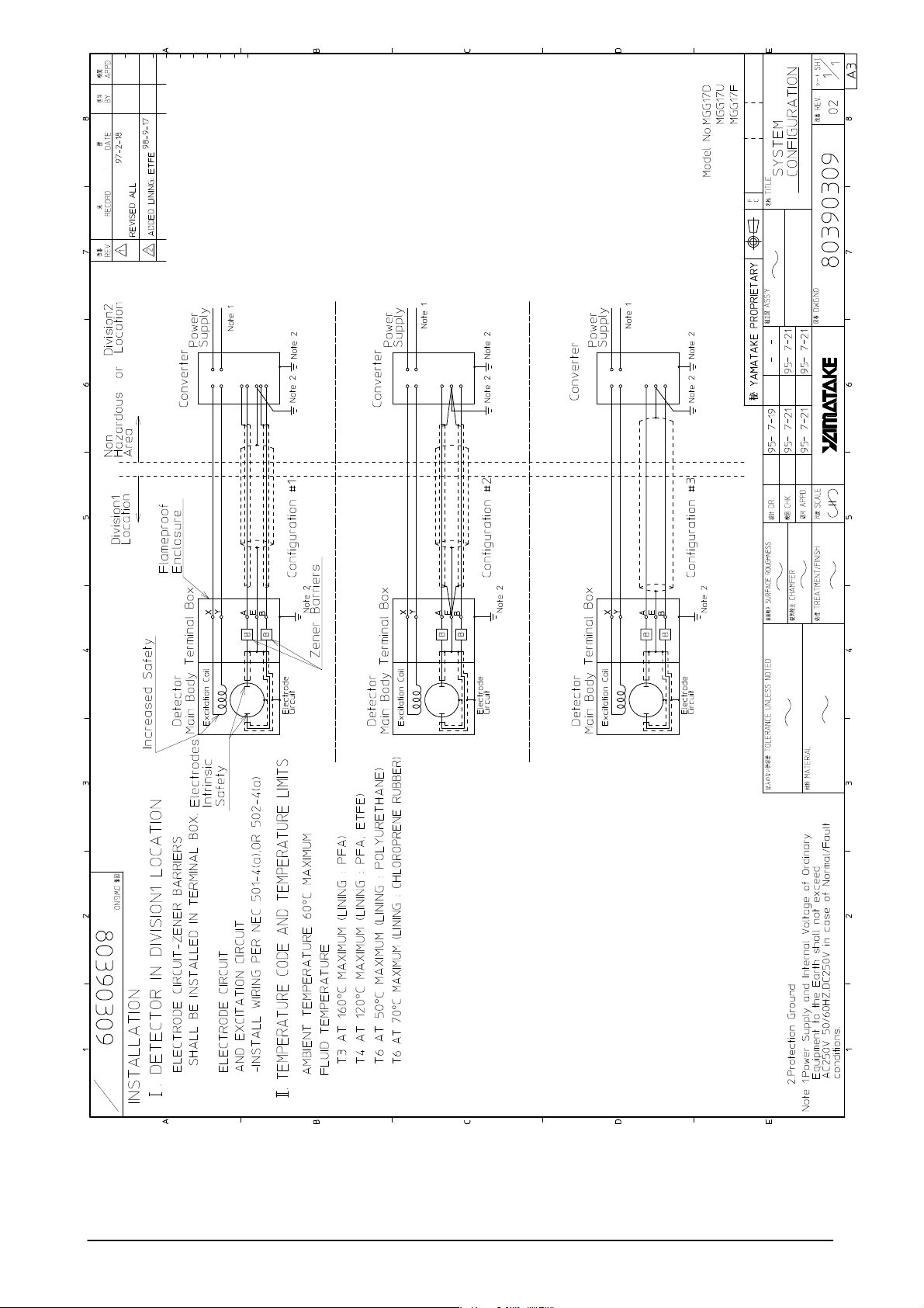
Electrical Wiring (3)
Grounding
This flowmeter is of flameproof structure and exhibits the specified explosion-proof capability only when it is used strictly in accordance with the following installation specifications:
Figure 2-34 Grounding
Hazardous Area
Electromagnetic Flowmeter (Model MGG15)
Electromagnetic Flowmeter (Model MGG15/16/17)
Electrodes
(Intrinsic Safety Model)
Energizing Coil
(Increased
Safety Model)
Body
(Increased Safety Model)
Safety
Holding Device,
Signal Circuit
Terminal Box
(Flameproof Model
or Intrinsic Safety Model)
Note 3
Non-hazardous Area
Ordinary Measuring Instruments
(Models MG, KIX and KIC)
Power Supply
Note 4
Caution for TIIS
Caution for
FM/CSA
Note 1 Neither input power supply voltage to ground, nor voltage inside
the ordinary measuring instruments should exceed 250V ac (50/
60 Hz) or 250V dc during normal or abnormal operation.
The energizing voltage should not exceed 45V dc, and the energizing current should not exceed 200mA.
2. Ambient temperature for the flowmeter should be 60°C.
3. Classification 3 Grounding should be employed.
4. Classification 4 Grounding should be employed.
Note 1. Power supply and internal voltage of ordinary equipment to the
earth shall not exceed AC250V 50/60Hz, DC250V in case of normal/formal conditions.
2. Ambient temperature is from –10 to 60°C
3. Process temperature is from –40 to 160°C
4. Power supply and internal voltage of Ordinary Equipment to the
Earth shall not exceed AC250V 50/60Hz. DC260V in case of
Normal/Fault.
5. Protection Ground.
2 - 44
Page 66

Chapter 3 - Maintenance of the Device
Introduction
For the device loop diagrams for troubleshooting and maintenance, refer to
the Converter user manual .
3 - 1
Page 67

MEMO
3 - 2
Page 68

INDEX
D
Detector ................................ 1-4,1-6,1-8
connection to the converter ..........2-42
E
Electrical conduit connection .......... 1-10
Electrodes… ......................... 1-5,1-7,1-9
cover .................................. 1-5,1-7,1-9
installation position ................. 1-4,1-6
Excitation terminal ..........................1-10
F
Flange ................................................ 1-9
shape ............................................. 2-30
Flow direction mark ............. 1-5,1-7,1-9
Flow rate measurement system .........1-2
Fluid to be measured .........................2-2
G
Gasket..............................................2-32
Grounding ring ........................... 1-7,1-9
Grounding terminal .........................1-10
W
Wiring, electrical............................. 2-42
I
Installation, selection of method
according to material ........... 2-13,2-33
Installation on pipe .......................... 2-14
Installation of the device ...................2-1
Grounding of the device ...... 1-10,2-43
Installation position ........................... 2-4
Installation site, criteria for selection of
......................................................2-2
S
Signal terminal ................................1-10
T
Terminal box ........................ 1-5,1-7,1-9
cover .................................. 1-5,1-7,1-9
direction..........................................2-6
Torque fastening ...................... 2-8,2-27
Index - 1
Page 69

Page 70

Terms and Conditions
We would like to express our appreciation for your purchase and use of Azbil Corporation’s products.
You are required to acknowledge and agree upon the following terms and conditions for your purchase of Azbil Corporation’s products (system
products, field instruments, control valves, and control products), unless otherwise stated in any separate document, including, without limitation,
estimation sheets, written agreements, catalogs, specifications and instruction manuals.
1. Warranty period and warranty scope
1.1 Warranty period
Azbil Corporation’s products shall be warranted for one (1) year from the date of your purchase of the said products or the delivery of the
said products to a place designated by you.
1.2 Warranty scope
In the event that Azbil Corporation’s product has any failure attributable to azbil during the aforementioned warranty period, Azbil
Corporation shall, without charge, deliver a replacement for the said product to the place where you purchased, or repair the said
product and deliver it to the aforementioned place. Notwithstanding the foregoing, any failure falling under one of the following shall
not be covered under this warranty:
(1) Failure caused by your improper use of azbil product (noncompliance with conditions, environment of use, precautions, etc. set
forth in catalogs, specifications, instruction manuals, etc.);
(2) Failure caused for other reasons than Azbil Corporation’s product;
(3) Failure caused by any modification or repair made by any person other than Azbil Corporation or Azbil Corporation’s
subcontractors;
(4) Failure caused by your use of Azbil Corporation’s product in a manner not conforming to the intended usage of that product;
(5) Failure that the state-of-the-art at the time of Azbil Corporation’s shipment did not allow Azbil Corporation to predict; or
(6) Failure that arose from any reason not attributable to Azbil Corporation, including, without limitation, acts of God, disasters, and
actions taken by a third party.
Please note that the term “warranty” as used herein refers to equipment-only-warranty, and Azbil Corporation shall not be liable for any
damages, including direct, indirect, special, incidental or consequential damages in connection with or arising out of Azbil Corporation’s
products.
2. Ascertainment of suitability
You are required to ascertain the suitability of Azbil Corporation’s product in case of your use of the same with your machinery,
equipment, etc. (hereinafter referred to as “Equipment”) on your own responsibility, taking the following matters into consideration:
(1) Regulations and standards or laws that your Equipment is to comply with.
(2) Examples of application described in any documents provided by Azbil Corporation are for your reference purpose only, and
you are required to check the functions and safety of your Equipment prior to your use.
(3) Measures to be taken to secure the required level of the reliability and safety of your Equipment in your use
Although azbil is constantly making efforts to improve the quality and reliability of Azbil Corporation’s products, there exists
a possibility that parts and machinery may break down. You are required to provide your Equipment with safety design such
as fool-proof design,*
physical injuries, fires, significant damage, and so forth. Furthermore, fault avoidance,*3 fault tolerance,*4 or the like should be
incorporated so that the said Equipment can satisfy the level of reliability and safety required for your use.
*1. A design that is safe even if the user makes an error.
*2. A design that is safe even if the device fails.
*3. Avoidance of device failure by using highly reliable components, etc.
*4. The use of redundancy.
3. Precautions and restrictions on application
3.1 Restrictions on application
Please follow the table below for use in nuclear power or radiation-related equipment.
Nuclear power quality*5 required Nuclear power quality*5 not required
Within a radiation
controlled area*
Outside a radiation
controlled area*
Cannot be used (except for limit switches for
6
nuclear power*7)
Cannot be used (except for limit switches for
6
nuclear power*7)
1
and fail-safe design*2 (anti-flame propagation design, etc.), whereby preventing any occurrence of
Cannot be used (except for limit switches for
nuclear power*7)
Can be used
*5. Nuclear power quality: compliance with JEAG 4121 required
*6. Radiation controlled area: an area governed by the requirements of article 3 of “Rules on the Prevention of Harm from
Ionizing Radiation,” article 2 2 4 of “Regulations on Installation and Operation of Nuclear Reactors for Practical Power
Generation,” article 4 of “Determining the Quantity, etc., of Radiation-Emitting Isotopes,”etc.
*7. Limit switch for nuclear power: a limit switch designed, manufactured and sold according to IEEE 382 and JEAG 4121.
Any Azbil Corporation’s products shall not be used for/with medical equipment.
The products are for industrial use. Do not allow general consumers to install or use any Azbil Corporation’s product. However, azbil
products can be incorporated into products used by general consumers. If you intend to use a product for that purpose, please contact
one of our sales representatives.
3.2 Precautions on application
you are required to conduct a consultation with our sales representative and understand detail specifications, cautions for operation,
and so forth by reference to catalogs, specifications, instruction manual, etc. in case that you intend to use azbil product for any purposes
specified in (1) through (6) below. Moreover, you are required to provide your Equipment with fool-proof design, fail-safe design, antiflame propagation design, fault avoidance, fault tolerance, and other kinds of protection/safety circuit design on your own responsibility
to ensure reliability and safety, whereby preventing problems caused by failure or nonconformity.
Page 71

(1) For use under such conditions or in such environments as not stated in technical documents, including catalogs, specification,
and instruction manuals
(2) For use of specific purposes, such as:
* Nuclear energy/radiation related facilities
[When used outside a radiation controlled area and where nuclear power quality is not required]
[When the limit switch for nuclear power is used]
* Machinery or equipment for space/sea bottom
* Transportation equipment
[Railway, aircraft, vessels, vehicle equipment, etc.]
* Antidisaster/crime-prevention equipment
* Burning appliances
* Electrothermal equipment
* Amusement facilities
* Facilities/applications associated directly with billing
(3) Supply systems such as electricity/gas/water supply systems, large-scale communication systems, and traffic/air traffic control
systems requiring high reliability
(4) Facilities that are to comply with regulations of governmental/public agencies or specific industries
(5) Machinery or equipment that may affect human lives, human bodies or properties
(6) Other machinery or equipment equivalent to those set forth in items (1) to (5) above which require high reliability and safety
4. Precautions against long-term use
Use of Azbil Corporation’s products, including switches, which contain electronic components, over a prolonged period may degrade
insulation or increase contact-resistance and may result in heat generation or any other similar problem causing such product or switch
to develop safety hazards such as smoking, ignition, and electrification. Although acceleration of the above situation varies depending
on the conditions or environment of use of the products, you are required not to use any Azbil Corporation’s products for a period
exceeding ten (10) years unless otherwise stated in specifications or instruction manuals.
5. Recommendation for renewal
Mechanical components, such as relays and switches, used for Azbil Corporation’s products will reach the end of their life due to wear by
repetitious open/close operations.
In addition, electronic components such as electrolytic capacitors will reach the end of their life due to aged deterioration based on
the conditions or environment in which such electronic components are used. Although acceleration of the above situation varies
depending on the conditions or environment of use, the number of open/close operations of relays, etc. as prescribed in specifications
or instruction manuals, or depending on the design margin of your machine or equipment, you are required to renew any Azbil
Corporation’s products every 5 to 10 years unless otherwise specified in specifications or instruction manuals. System products, field
instruments (sensors such as pressure/flow/level sensors, regulating valves, etc.) will reach the end of their life due to aged deterioration
of parts. For those parts that will reach the end of their life due to aged deterioration, recommended replacement cycles are prescribed.
You are required to replace parts based on such recommended replacement cycles.
6. Other precautions
Prior to your use of Azbil Corporation’s products, you are required to understand and comply with specifications (e.g., conditions and
environment of use), precautions, warnings/cautions/notices as set forth in the technical documents prepared for individual Azbil
Corporation’s products, such as catalogs, specifications, and instruction manuals to ensure the quality, reliability, and safety of those
products.
7. Changes to specifications
Please note that the descriptions contained in any documents provided by azbil are subject to change without notice for improvement
or for any other reason. For inquires or information on specifications as you may need to check, please contact our branch offices or
sales offices, or your local sales agents.
8. Discontinuance of the supply of products/parts
Please note that the production of any Azbil Corporation’s product may be discontinued without notice. After manufacturing is
discontinued, we may not be able to provide replacement products even within the warranty period.
For repairable products, we will, in principle, undertake repairs for five (5) years after the discontinuance of those products. In
some cases, however, we cannot undertake such repairs for reasons, such as the absence of repair parts. For system products, field
instruments, we may not be able to undertake parts replacement for similar reasons.
9. Scope of services
Prices of Azbil Corporation’s products do not include any charges for services such as engineer dispatch service. Accordingly, a separate
fee will be charged in any of the following cases:
(1) Installation, adjustment, guidance, and attendance at a test run
(2) Maintenance, inspection, adjustment, and repair
(3) Technical guidance and technical education
(4) Special test or special inspection of a product under the conditions specified by you
Please note that we cannot provide any services as set forth above in a nuclear energy controlled area (radiation controlled area) or at a
place where the level of exposure to radiation is equivalent to that in a nuclear energy controlled area.
AAS-511A-014-10
Page 72

Page 73

'RFXPHQW1XPEHU
&00**
'RFXPHQW1DPH
0DJQ
(OHFWURPDJQHWLF)ORZPHWHU Explosion-proof type Detector
0RGHO0**/
8VHU¶V0DQXDO
'DWH1st Edition
H: )/(;+3/86+
: July
5th Edition: Feb. 2019
,VVXHG(GLWHGE\$]ELO&RUSRUDWLRQ
1997
Page 74

 Loading...