

Page 1
CM2-MGG31F-2001
MagneW PLUS+
Electromagnetic Flowmeter
F
oundation Fieldbus Transmitter
Model MGG14C
User’s Manual
Page 2

Copyright, Notices and Trademarks
© 2014–2018 Azbil Corporation All Rights Reserved.
Be sure that the user receives this manual before the product is used.
While this information is presented in good faith and believed to
be accurate, Azbil Corporation disclaims the implied warranties of
merchantability and tness for a particular purpose and makes no
express warranties except as may be stated in its written agreement
with and for its customer.
In no event shall Azbil Corporation be liable to anyone for any
indirect, special or consequential damages. is information and
specications in this document are subject to change without notice.
MagneW™ is a trademark of Azbil Corporation.
F™ Fieldbus is a trademark of FieldComm Group.
Precaution
is device is designed and manufactured for the use of general
applications.
Do not use this device for the nuclear applications and applications
which are directly related to the human life. Also do not use this
device in the radiation controlled area.
In case the device is used in the following applications, please
make sure to use the device with the system designed as failsafe/
redundant and the system should be maintained periodically.
• Safety device for human body protection
• Directly control the transport machine
• Aircra
• Space appliance
Azbil Corporation disclaims any liability for damages caused by
any of accidents/results by the above application.
Page 3
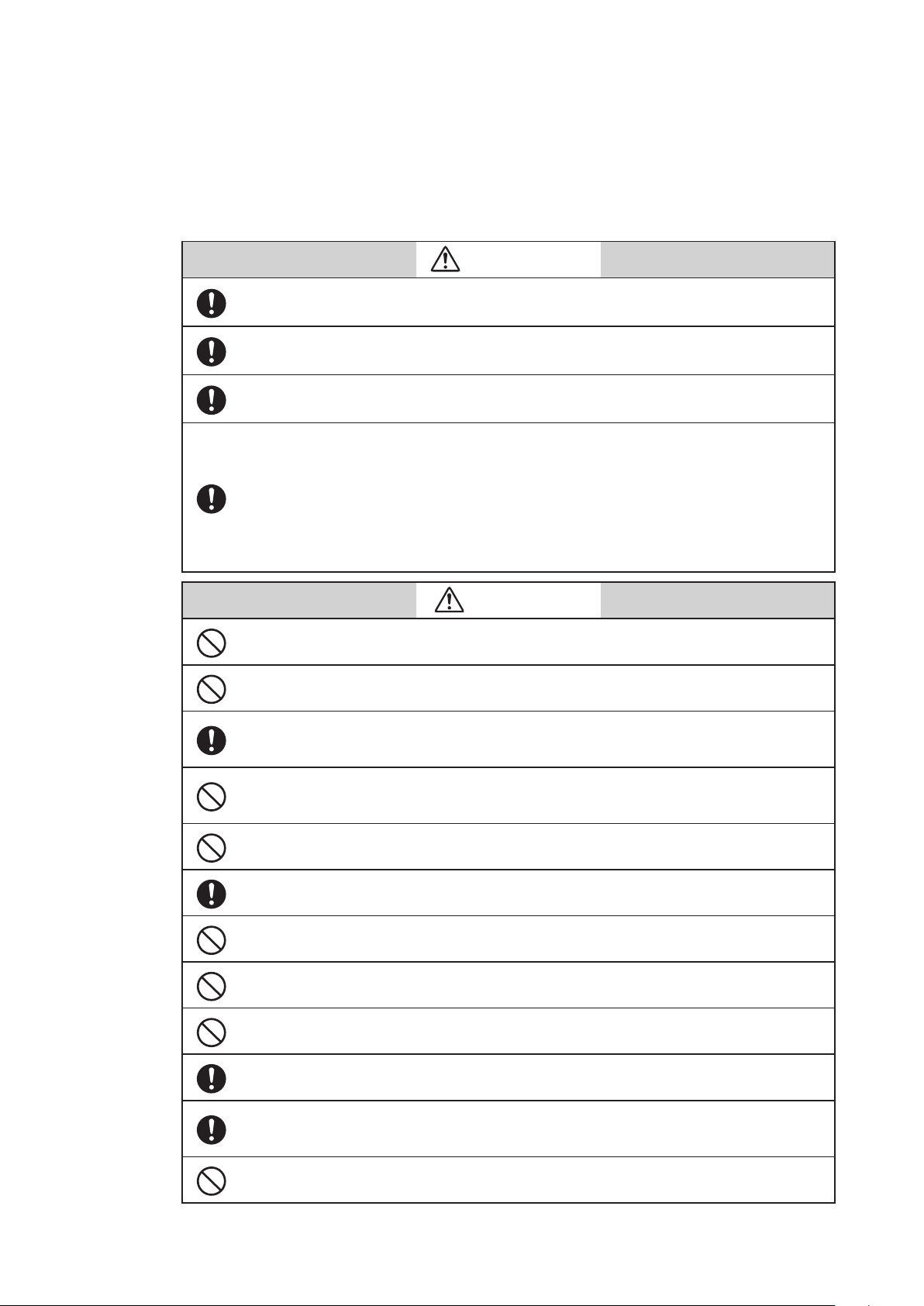
SAFETY PRECAUTIONS
About Icons
e safety precautions described in this manual are indicated by various icons.
Please be sure you read and understand the icons and their meanings described below before reading the
rest of the manual.
Safety precautions are intended to ensure the safe and correct use of this product, to prevent injury to the
operator and others, and to prevent damage to property.
Be sure to observe these safety precautions.
Warnings are indicated when mishandling this product might
WARNING
CAUTION
result in death or serious injury.
Cautions are indicated when mishandling this product might result in
minor injury to the user, or only physical damage to the product.
Examples
In describing the product, this manual uses the icons and conventions listed below
.
Use caution when handling the product.
The indicated action is prohibited.
Be sure to follow the indicated instructions.
SAFETY REQUIREMENTS
To reduce risk of electric shock which could cause personal injury, follow all safety notices in this
documentation.
WARNING
This symbol warns the user of a potential shock hazard where hazardous live voltages
may be accessible.
i
Page 4
Safety messages
Carefully read this section before installing or operating this device.
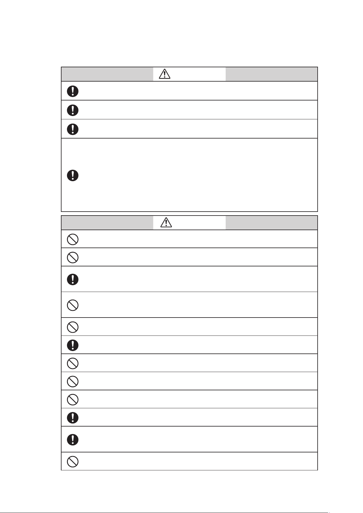
Cautions for installation
Installation of the device should be done by the expert from the safety perspective.
In case of the installation in the hazardous area, follow the regulation/guidance of the
explosion-proof.
In case of the installation in the hazardous area, select the explosion-protected apparatus.
Do not use the non-explosion-protected apparatus in the hazardous area.
Install the device in the environment where the following is within in the specifications
listed in the specification sheet.
• Ambient temperature, process fluid temperature
• Process fluid pressure
• Humidity
• Vibration
• Power supply voltage
Environment which exceeds the specifications may cause fire or device damage and it may
cause injury.
WARNING
CAUTION
DO NOT use the installed device as foot hold. It may cause the damage of the device.
DO NOT hit the glass of the device by tools. It may cause the damage of the device.
Install the device in a location with an ambient temperature of -25 °C to 60°C (-13 °F to
140 °F) and an ambient humidity of 5 to 100% RH to prevent device malfunction or output
errors.
DO NOT install the device near high-current power lines, motors, or transformers to prevent damage from electromagnetic induction, which can cause device malfunction or
output errors.
DO NOT use the device to ground a welder. It can damage the device.
Be sure to ground the welding power transformer when welding near the device to avoid
output errors.
DO NOT install the device in the severe vibration area or in corrosive environment. It may
damage the device, or cause the fume of the device.
DO NOT install the device on the bridge or deck of the ship.
DO NOT install the device on in the severe vibration area on the ship.
Be sure to use the metal conduit for the cables between the remote style transmitter and
flowtube.
Be sure to install the flowtube with a distance of 500mm minimum from the other flowtube. Magnetic field generated by a flowtube may affect the other flowtube and it may
cause the output errors.
DO NOT install the device in a location subject to direct sunlight, wind, rain, severe vibration, or in a highly corrosive atmosphere. The transmitter and flowtube can be damaged.
ii
Page 5
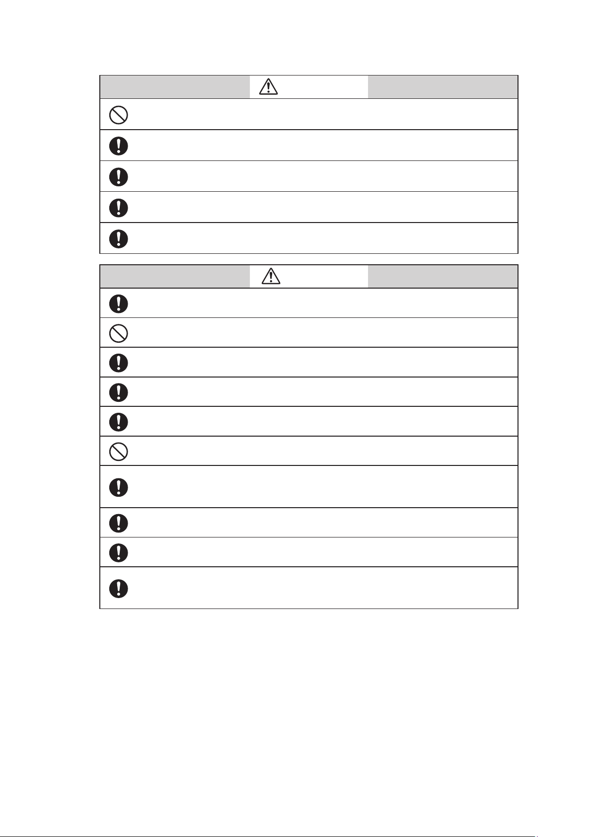
Cautions for wiring
DO NOT wire with wet hands. DO NOT wire while the circuit is alive. It may cause electrical
shock.
ELECTRIC SHOCK HAZARD! Turn the power supply OFF before opening the transmitter
cover.
Wiring of the device should be done by the expert from safety perspective.
Wire the cables to the correct terminal. Incorrect wiring may damage the device or cause
the fume of the device.
Connect the correct power supply. Incorrect power supply may damage the device or
cause the fume of the device.
Be sure to properly ground the device. Improper grounding may cause the output errors
DO NOT give impact to the device. It may cause the damage of the device.
WARNING
CAUTION
Be sure to use the power supply with the overcurrent protection function.
Be sure proper wiring. Incorrect wiring may cause the damage of the device.
Be sure to properly tighten the terminal cover on the terminal box so that water does not
penetrate in the terminal.
DO NOT connect AC power supply to the DC power supply model. The wrong power supply damages the device.
Turn off the Fieldbus power supply before connecting the Fieldbus cable to the transmitter. The transmitter or the Fieldbus power supply can be damaged. This type of damage is
not covered by Azbil Corporation’s warranty.
Be sure to plug all unused conduit connections with a water tight plug.
In case that a remote model is installed in a ship, the cables between the transmitter and
flowtube must be covered with a flexible metal conduit.
Switch the control equipment to manual control before terminating the device operation and shutting off the output to the control equipment. This action prevents the power
shut-off from directly affecting the control equipment.
iii
Page 6

iv
Page 7

Table of Contents
1. Introduction ...........................................................1-1
1.1 System configuration ..............................................................1-1
1.2 F Fieldbus .............................................................1-2
1.3 Main components .................................................................1-4
1.4 Local user interface ...............................................................1-5
2. Overview of MagneW PLUS+ Foundation Fieldbus .........................2-1
2.1 Overview ........................................................................2-1
2.2 Structure of MagneW PLUS+ F Fieldbus .....................................2-1
2.2.1 System/network Management VFD ............................................2-1
2.2.2 Function Block VFD ........................................................2-2
2.2.3 Function block .............................................................2-2
2.2.4 Transducer Block ...........................................................2-2
2.3 VFD/Object correlation diagram ....................................................2-3
2.4 Wiring .........................................................................2-4
2.5 Others .........................................................................2-5
3. Installation ............................................................3-1
3.1 Before installing electromagnetic flowmeter ..........................................3-2
3.2 Installation of transmitter ..........................................................3-3
4. Startup and Shutoff ....................................................4-1
4.1 Startup .........................................................................4-1
4.2 Steps before measurement ..........................................................4-2
4.3 Shutoff .........................................................................4-5
5. Basic Settings by Fieldbus Communication ...............................5-1
5.1 Fieldbus communication menu .....................................................5-2
5.2 Zero adjustment ..................................................................5-3
5.3 Basic settings .....................................................................5-4
6. Maintenance and Troubleshooting ......................................6-1
6.1 Troubleshooting ..................................................................6-1
6.2 Input of simulated signals from calibrator ............................................6-6
6.3 Measurement of excitation current ..................................................6-7
Appendix A. View List .................................................... A-1
Appendix B. Parameter List .............................................. B-1
Appendix C. Menu Configuration ..........................................C-1
v
Page 8

vi
Page 9
1. Introduction
This chapter contains an overview of the model MGG14C MagneW PLUS+ Flowmeter
and F Fieldbus system. It describes available configurations and provides
definitions for all the major parts of the transmitter.
MagneW PLUS+ Flowmeter
Thank you for purchasing the Azbil Corporation model MGG14C MagneW PLUS+
Flowmeter This system features:
• Advanced multi-variable capacity
• Digital panel display
• Intuitive, versatile operator interface with large characters and backlit liquid crystal
display
• I/O Capacity
• Flexible digital communication using the F Fieldbus
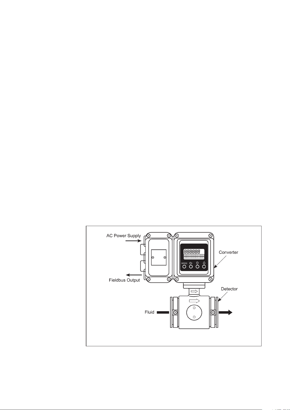
1.1 System configuration
The model MGG14C MagneW PLUS+ Flowmeter consists of a flowtube and a transmitter
which operate on the principles of Faraday’s law. The flowmeter is available in two
configurations:
Integral
Remote
– The transmitter is mounted directly on the flowtube and they are installed as an
integrated unit on the fluid pipe.
– The transmitter and flowtube are installed separately and connected together
via cables
Figure1-1 Indegral system
1-1
Page 10
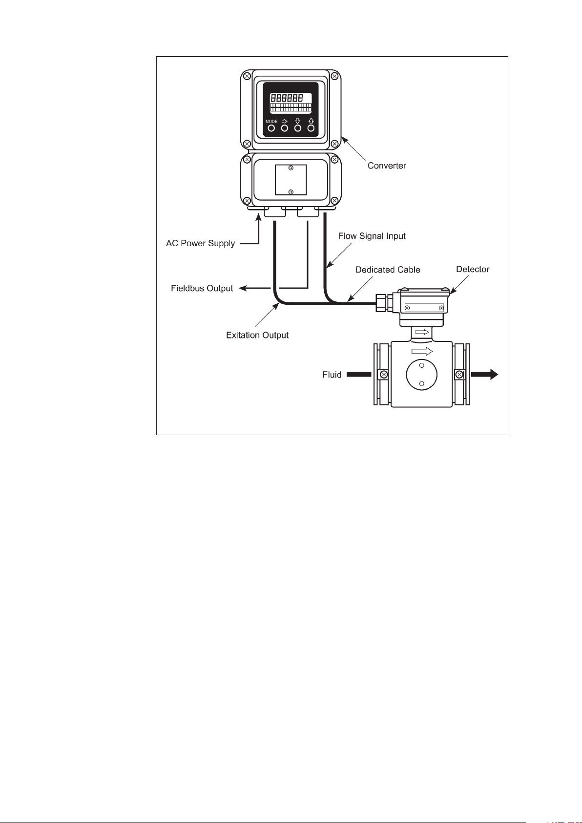
1.2 Foundation Fieldbus
The F Fieldbus provides communications and programmability for a single or
multiple flowmeter system. Some features of the fieldbus include:
• Complies with F Fieldbus H1 (31.25 kbps voltage mode bus)
specifications.
• Supports the standard Analog Input (AI) function block.
• Is an externally powered device – AC and DC powered models available.
• Comes with Enhanced Device Description (EDD) files and a Capability File (CF) for
automatic configuration.
The following figure shows a system in which the flow rate is output with a F
Fieldbus.
Figure1-2 Remote system
1-2
Page 11
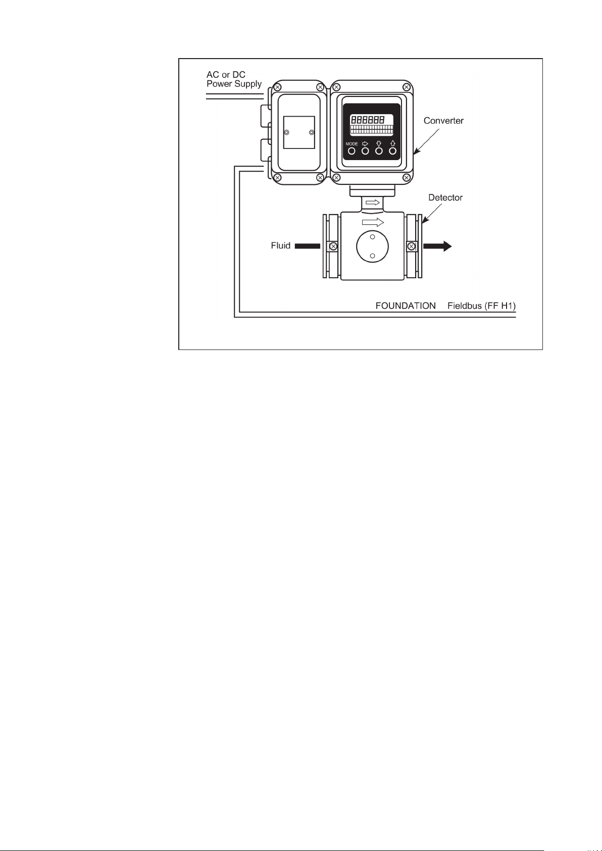
Figure1-3 System using a Foundation Fieldbus
1-3
Page 12
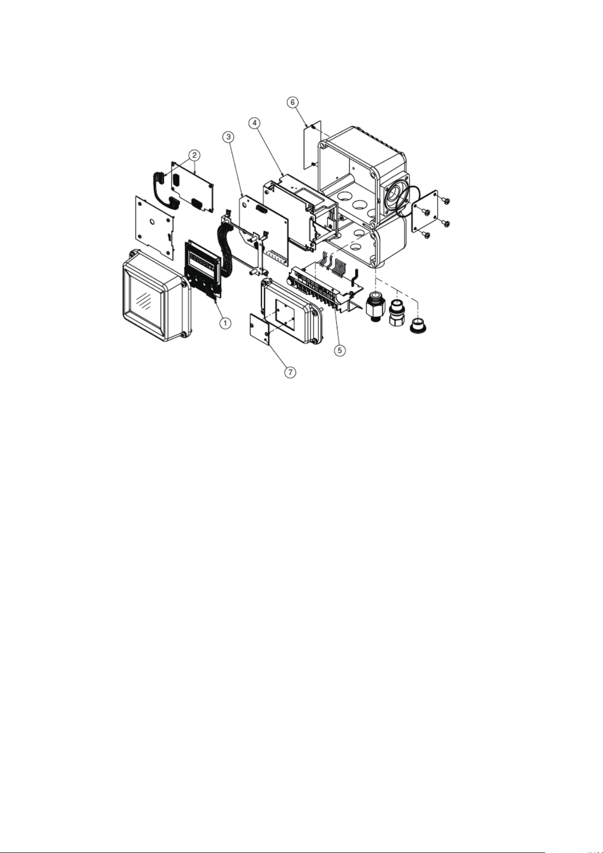
1.3 Main components
The transmitter consists of the components shown in the figure below.
Figure1-4 Main components
(1)
Local user interface
can be accessed using the four infrared sensor keys on the panel.
(2)
Fieldbus interface board
(3)
Main board
(4)
Power supply board
(5)
Terminal
(6)
Name plate
manufacture and the flowtube constant (EX) for the flowmeter.
(7)
Tag number plate
– This board includes fundamental functions of the flow measurement.
– Encloses the input/output terminals. Contains an integrated 12 kV, 1000A isolator.
– Indicates model numbers and production numbers, power supply requirements, date of
– Indicates the instantaneous flow rate or the totalized valve. The flowmeter functions
– Includes the fieldbus communication function.
– There are two types, AC power supply, and DC power supply type.
– Indicates the tag number as specified in the product order.
1-4
Page 13
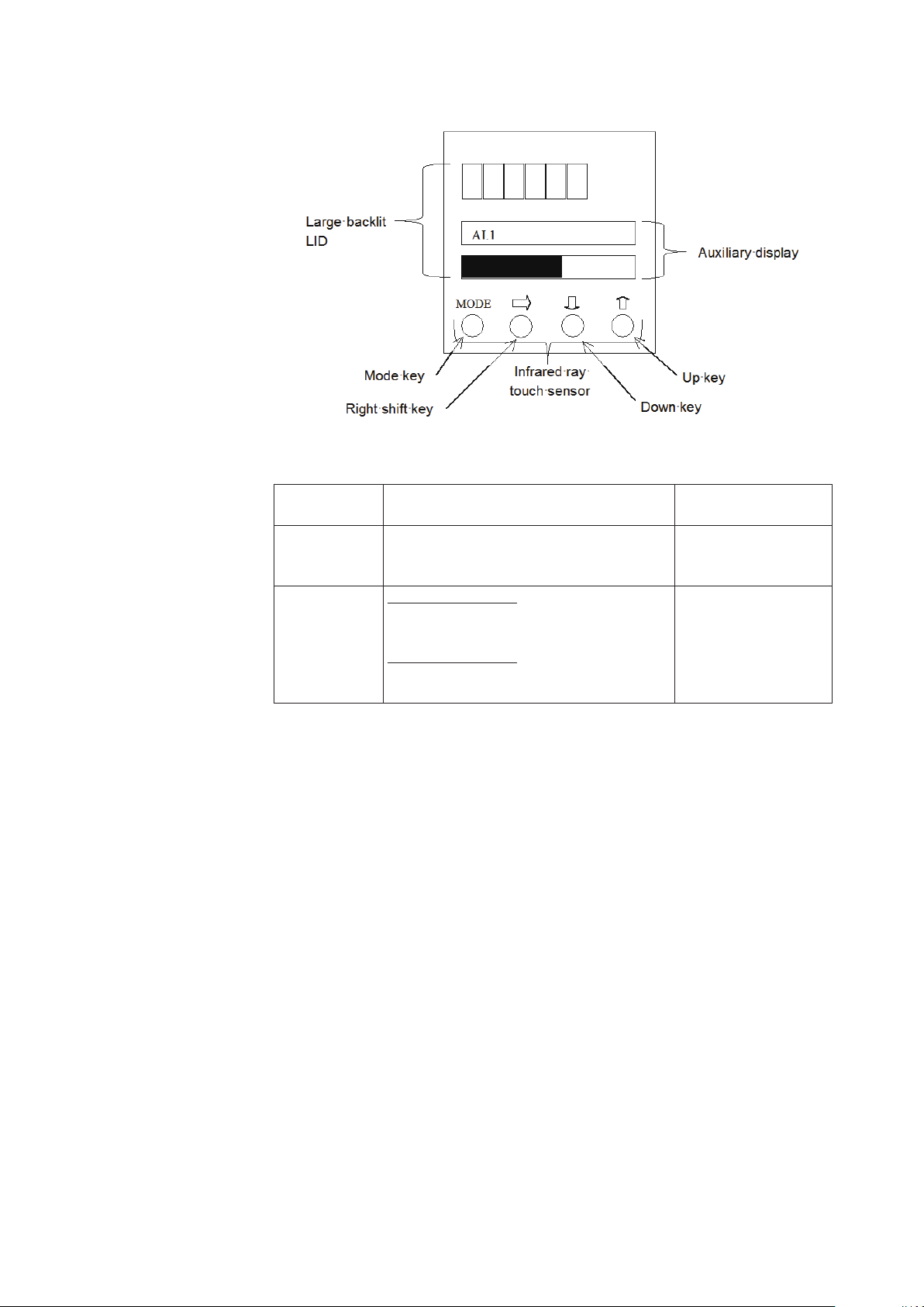
1.4 Local user interface
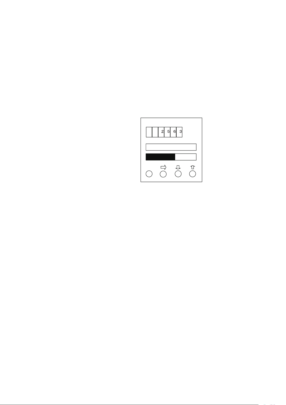
Figure1-5 Local user interface
Display MEASURING MODE
Main display Indicates a value set by PARAM_SELECTION
under the block selected by BLOCK_TAG_SEL.
Indicates maximum four values cyclically.
Auxiliary display
Upper auxiliary display
Indicates the information of [Tag, unit, or status]
set by DISPLAY_INFO_SEL cyclically.
Lower auxiliary display
Indicates percent flow rate with bar indicator.
Range is set by EU_100, and EU_0.
Other than MEASURING
MODE
Indicates flow velocity.
Indicates procedures for
the parameter setting or
adjustment.
1-5
Page 14
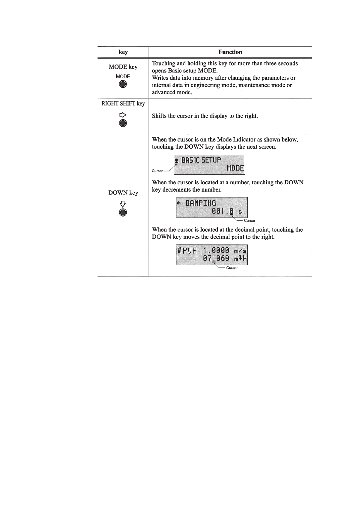
The following table is a summary of the functions of each of the keys.
1-6
Page 15
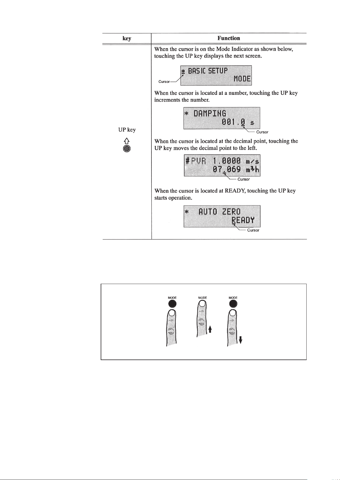
How to operate the infrared touch sensor
For best results, approach the key from below and completely cover the circle. Then move
your finger straight down to its original position. These motions ensure correct operation.
Moving sideways across the keys can accidentally activate the wrong control.
Figure1-6 Using the touch senser keys
1-7
Page 16

Local user interface operation
The following table describes the functions available in each mode.
Display
MEASURING MODE This is the normal operational mode and indicates the measuring
BASIC SETUP MODE This mode is used to change data settings that must be recorded or
MAINTENANCE MODE
ADVANCED MODE This mode is used to apply some specific noise immunity functions.
MEASURING MODE
Other than MEASURING MODE
status.
Each time the MEASURING MODE is selected, data is written into
memory. Settings entered in other modes are held in temporary
memory for two minutes, but will return to the previously saved
value unless the MEASURING MODE is selected to save the data.
The only exception is the counter, which is always saved into memory
immediately.
changed frequently. These settings include:
TAG NO.
Damping time constant
Auto zero
Detector data
This mode is used when adjustment or verification is required for
regular maintenance of the system or when troubleshooting the
system. This mode includes:
Shipping information
Output adjustment
Gain adjustment
This mode is further divided into the following two modes:
OUTPUT CHECK MODE
CALIBRATION MODE
This mode includes:
Damping
Manual zero
Averaging
Auto spike Cut
Coefficient
Drop out
Low-flow cut off
Flow direction change
1-8
Page 17
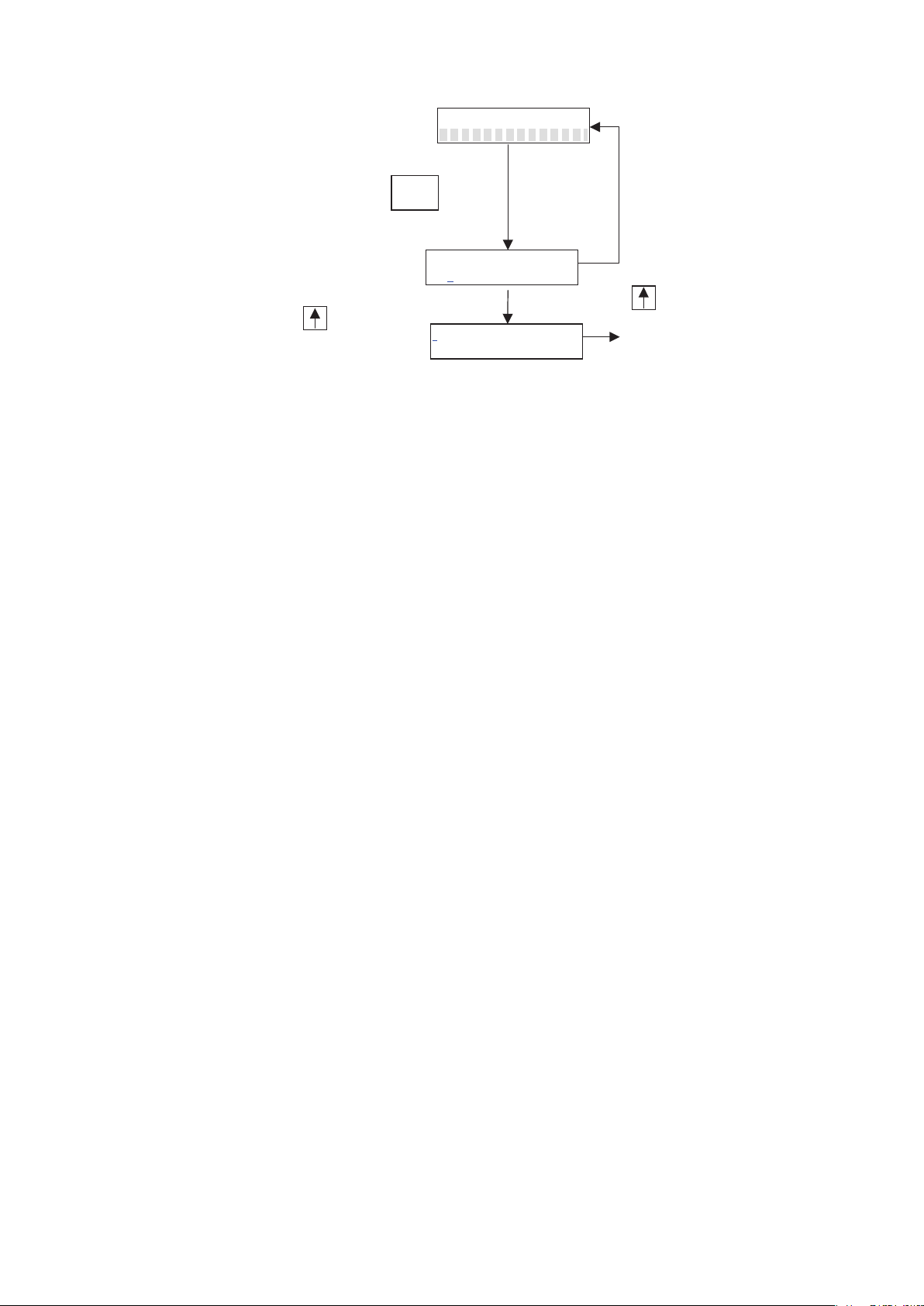
AI – 01 PV
The screen returns to MEASURING mode
MEASURING MODE
to BASIC SETUP
Move the cursor under “Y” and
press key.
Push 3
seconds
MODE
ENTER BASIC SET
YES OR
NO
in case of no operation for 8 seconds.
Move the cursor under “N” and
* BASIC SETUP
MODE
Figure1-7 How to enter BASIC SETUP
* In the BASIC SETUP mode, flow velocity in m/s appears on the upper auxiliary display.
* After entering the BASIC SETIP mode, if do not operate anything for 10 minutes, the
screen automatically returns from BASIC SETUP mode to MEASURING MODE.
1-9
Page 18
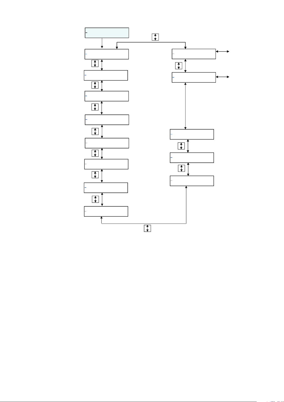
*
2 seconds later
BASIC SETUP
to Fig1-11 screen
*
PD TAG 1/2
YA – RC - 001
*
PD TAG 2/2
YA – RC - 001
*
NODE ADRESS
FFh
*
MEMO
*
DAMPING
*
AUTO ZERO
READY
MODE
XXXXXXXX
003.0 s
s
*
MODE ENTER
ADVANCED
*
MODE ENTER
MAINTENANCE
*
DENSITY
*
SVR 10.000 m/s
1.0000
70.686 t/h
to Fig1-10 screen
*
MGG DIA
M
*
DUMMY
EX 300.0
50.0
0
Figure1-8 BASIC SETUP MODE
*
PVR 10.000 m/s
70.686
m3/h
1-10
Page 19
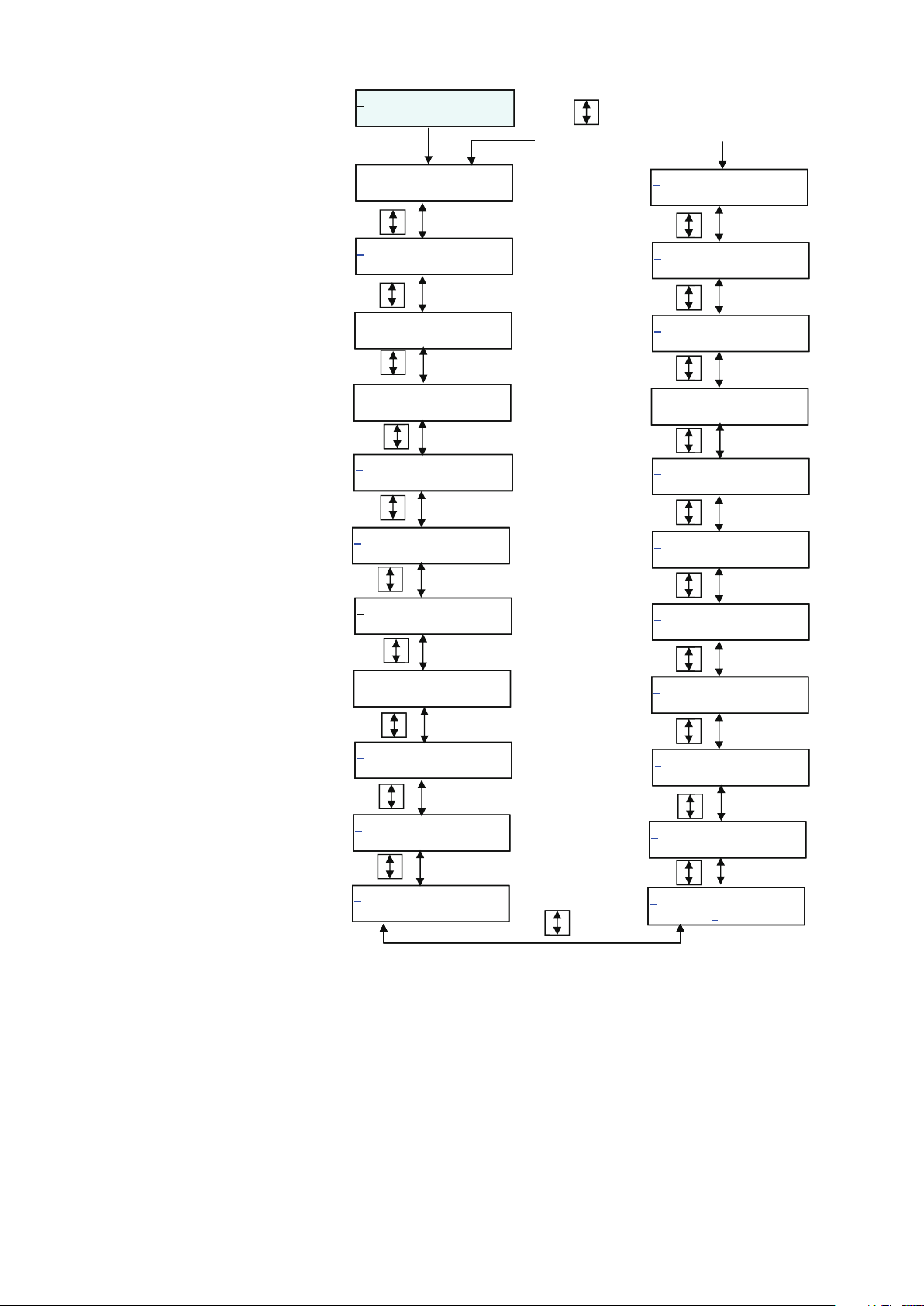
2 seconds later
& ADVANCED
MODE
& COEFFICIENT
1.0000
& MANUAL ZERO
READY
& AVARAGING
OFF
& PV SPIKE CUT
OFF
& PV SPIKE CUT
TIME 00.0 s
& PV SPIKE CUT
LEVEL 00.0 %
& SV SPIKE CUT
OFF
& MODE RETURN
BASIC SETUP
& FLOW SWITCH 2
HYSTERISIS
& FLOW SWITCH 2
SP
.00000 t/h
& FLOW SWITCH 2
MODE LOW
& FLOW SWITCH 2
SOURCE SV
& FLOW SWITCH 1
HYSTERISIS 0%
& FLOW SWITCH 1
SP
.00000 m3/h
0%
& SV SPIKE CUT
TIME 00.0S
& SV SPIKE CUT
& PV L-FLOW CUT
LEVEL
& SV L-FLOW CUT
LEVEL
LEVEL 00.0 %
10%
10%
Figure1-9 ADVANCED MODE
& FLOW SWITCH 1
MODE LOW
& FLOW SWITCH 1
SOURCE
& FLOW DIRECTION
& EX FREQUENCY
PV
FORWARD
12.5 Hz
1-11
Page 20
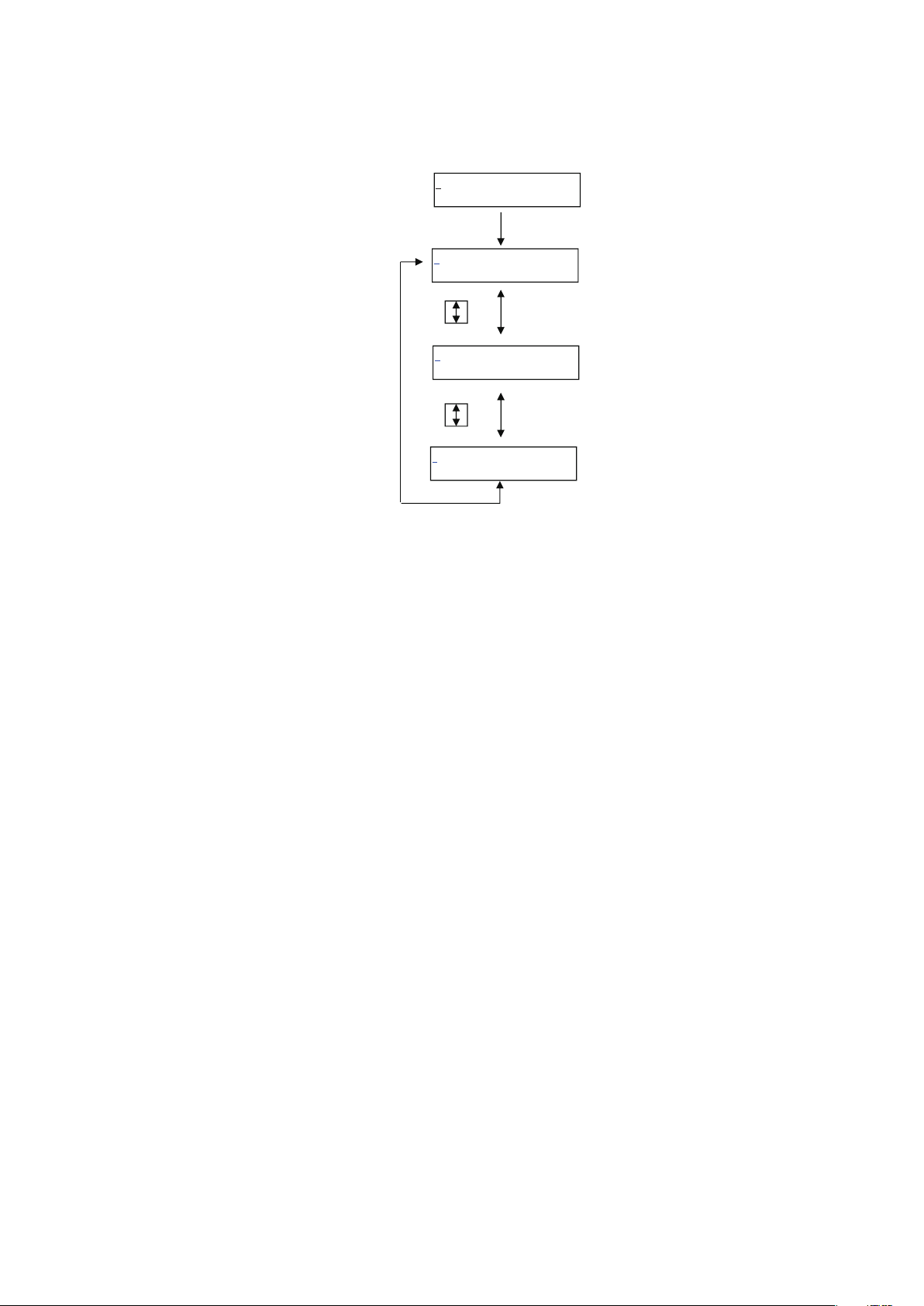
> MAINTENANCE
MODE
> CALIBRATION
> SHIPPING INFO
> MODE RETURN
BASIC SETUP
OFF
OFF
Figure1-10 MAINTENANCE MODE
1-12
Page 21
2. Overview of MagneW PLUS+ Foundation Fieldbus
2.1 Overview
This chapter contains an overview of the model MGG14C MagneW PLUS+ F
Fieldbus transmitter.
Model MGG14C MagneW
MagneW PLUS+ flowtube and measures the conductive fluid flow rate. It outputs the
following with the F Fieldbus protocol.
Primary value of Flow TB: volumetric flow rate
Secondary value of Flow TB: mass flow rate
Primary value of Diag TB: scale level by scale diagnostic
Those outputs are displayed on the following Display panel.
Fieldbus is a widely used bi-directional digital communication protocol for field devices
that enable the simultaneous output to many types of data to the process control system.
PLUS+ F Fieldbus transmitter is coupled with the
MODE
The MagneW
by the FieldComm Group, and provides interoperability between Azbil devices and those
produced by other manufacturers.
Fieldbus comes with software consisting of three AI function blocks that enable the
flexible implementation of systems.
PLUS+ Fieldbus communication type employs the specification standardized
2.2 Structure of MagneW PLUS+ Foundation Fieldbus
The MagneW PLUS+ contains two Virtual Field Devices (VFD), one is System/network
Management VFD and the other is Function block VFD.
2.2.1 System/network Management VFD
• Sets node addresses and Physical Device tags (PD Tag) necessary for communication.
• Controls the execution of function blocks.
• Manages operation parameters and communication resources (Virtual Communication
Relationship:VCR).
2-1
Page 22

2.2.2 Function Block VFD
It includes some objects to execute function block applications. Resource block, Function
block, and Transducer block are one of the objects.
Transducer block
2.2.3 Function block
AI * 2 (3) 30
DI 2 30 1800, 1900 For flow limit switches
PID 1 45 2000
AR 1 30 2100
TOT 2 30 2200, 2300 For totalization volume
Resource block
Function block
Alert object
Trend object
View object
Link object
Block
name
Number
• Manages the status of The
• Automatically informs the host of any detected faults or other problems
based on the NAMUR NE107.
It links together with Transducer block or other function block and
provides arithmetic processing and transmits.
It provides interface function between the hardware and function block.
It provides processing for the event or alarm generated in function block.
Object to transmit trend data collected in short time
Object that provides information of each parameter in the function block.
Objects that links the above mentioned objects.
Execution
time (ms)
INDEX Note
1500, 1600,
(1700)
MagneW PLUS+
For volumetric flow rate and mass flow rate
PID function block execute a control
algorithm to minimize the error as the
difference between a measured process
variable and desired setpoint.
It also has functions of cascade control, feed
forward control, and alarm detection.
Arithmetic block perform an arithmetical
operation to the flow measurement value.
hardware.
* Number of AI becomes three when selecting flow signal analysis function.
Flow signal analysis function will be provided as call factory basis. Consult your azbil
representative.
2.2.4 Transducer Block
Flow transducer block
Display transducer block Block that controls the LCD display
Diag transducer block Block that executes the diagnosis
Block name Description
Block that calculates the flow speed, volumetric flow rate,
and mass flow rate
2-2
Page 23
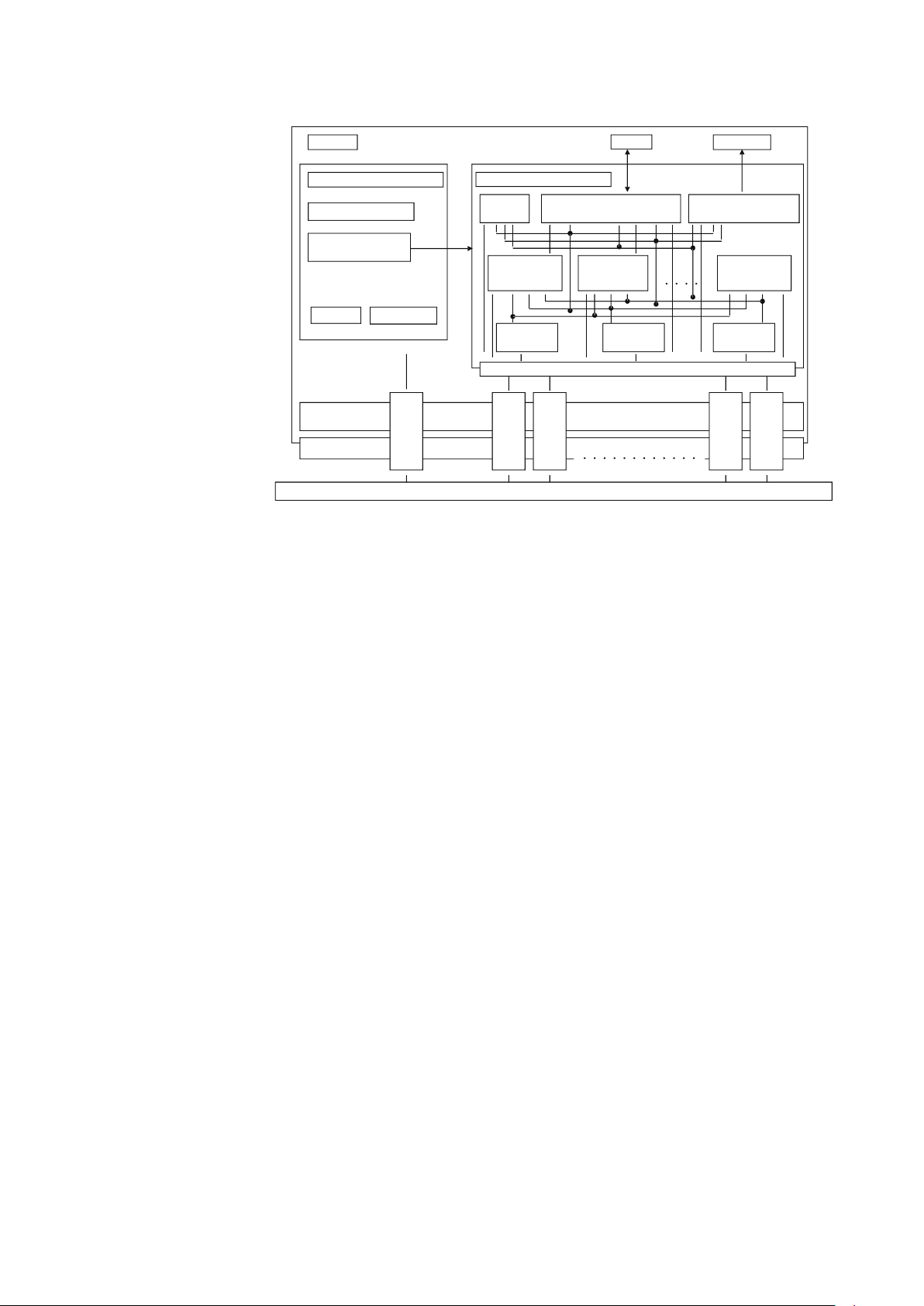
2.3 VFD/Object correlation diagram
Device
Basic information control
Function block
Control function
LAS
Communication stack
(FMS/FAS/DLL)
Physical layer (PHL)
H1 Fieldbus Line
/
VCR control
VCR VCR VCR VCR VCR
Function block VFD
Resource
block
AI
Function
Link object
FF standard transducer block
(FLOW/Positioner/Pressure)
View
Object
2-3
Figure2-1 VFD/Object correlation diagram
DI
Function
Senso r
Trend
Object
Display
Display transducer block
PID
Function
Alert
Object
2-3
Page 24

2.4 Wiring
The number of devices that can be connected to a single bus and the cable length vary
depending on system design. When constructing systems, both the basic and overall
design must be carefully considered to achieve optimal performance.
Fig 2-2 shows typical wiring to the Fieldbus network. The following are required for use
with Fieldbus devices:
• Terminator:
Fieldbus requires two terminators. Refer to the supplier for details of terminators that are
attached to the host.
• Field devices:
Connect Fieldbus communication type MagneW
PLUS+. Two or more MagneW PLUS+
devices or other devices can be connected.
• Host:
Used for accessing field devices. A dedicated host (such as DCS) is used for an
instrumentation line while dedicated communication tools are used for experimental
purposes. For operation of the host, refer to the instruction manual for each host. No
other details on the host are given in this manual.
• Cable:
Used for connecting devices. For laboratory or other experimental use, a twisted pair cable
2
two to three meters in length with a cross section of 0.9 mm
or more and a cycle period
of within 5 cm (2 inches) may be used. Termination processing depends on the type of
device being deployed. For MagneW PLUS+, use an M4 screw terminal claw. Some hosts
require a connector. Refer to Azbil Corporation when making arrangements to purchase
the recommended equipment. Connect the devices as shown in Figure 2-2. Connect
the terminators at both ends of the trunk, with a minimum length of the spur laid for
connection.
Table 2-1 Fieldbus cable
Classification Description Size Maximum length
2
A Type A Fieldbus cable 0.8 mm
B Type B Fieldbus cable 0.32 mm
C Type C Fieldbus cable 0.13 mm
D Type D Fieldbus cable 1.25 mm
(18AWG) 1900m
2
(22AWG) 1200m
2
(26AWG) 400m
2
(16AWG) 200m
Table 2-2 Resistance of the Fieldbus cable
Classification Maximum resistance @ 25ºC
A 22 /Km
B 56 /Km
C 132 /Km
D 20 /Km
2-4
Page 25
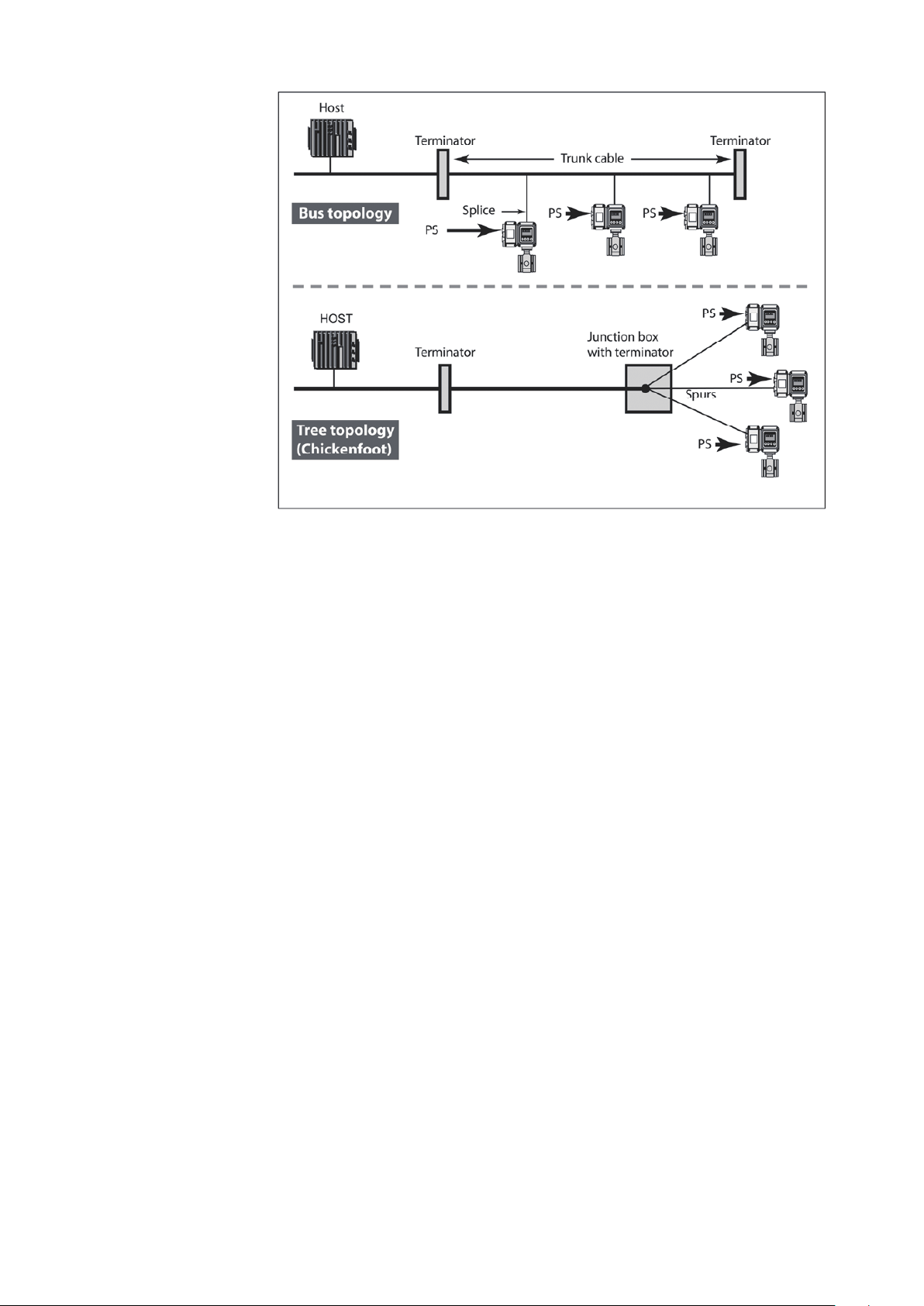
2.5 Others
Figure2-2 Cabling
Connect/disconnect the fieldbus devices
Before connecting/disconnecting the fieldbus device to the network, make sure this
activity does not affect the process.
Fieldbus network allows device connection/disconnection to the network while the device
circuit is alive. However from the process safety perspective, the device connection/
disconnection to the network after turn off the power is suggested.
Make sure to properly isolate the wires after disconnecting the device.
Non-fieldbus device
Non-fieldbus device is not allowed to connect to the fieldbus network.
Communication error and miss-wiring
If communication error appears, the device repeats sending the signal/message until it
is received by the host system. This kind of the communication error appears when the
wiring is improper.
Check the wiring if communication error appears.
2-5
Page 26

2-6
Page 27
3. Installation
Overview
Installation of the device should be done by the expert from the safety perspective.
In case of the installation in the hazardous area, follow the regulation/guidance of the
explosion-proof.
In case of the installation in the hazardous area, select the explosion-protected apparatus.
Do not use the non-explosion-protected apparatus in the hazardous area.
Install the device in the environment where the following is within in the specifications
listed in the specification sheet.
• Ambient temperature, process fluid temperature
• Process fluid pressure
• Humidity
• Vibration
• Power supply voltage
Environment which exceeds the specifications may cause fire or device damage and it may
cause injury.
This chapter describes the installation and wiring of the device in the following order:
- Criteria for selecting the installation environment
- Overview of the device installation
- Wiring of signal cables
WARNING
CAUTION
DO NOT use the installed device as foot hold. It may cause the damage of the device.
DO NOT hit the glass of the device by tools. It may cause the damage of the device.
Install the device in a location with an ambient temperature of -25 °C to 60°C (-13 °F to
140 °F) and an ambient humidity of 5 to 100% RH to prevent device malfunction or output
errors.
DO NOT install the device near high-current power lines, motors, or transformers to prevent damage from electromagnetic induction, which can cause device malfunction or
output errors.
DO NOT use the device to ground a welder. It can damage the device.
Be sure to ground the welding power transformer when welding near the device to avoid
output errors.
DO NOT install the device in the severe vibration area or in corrosive environment. It may
damage the device, or cause the fume of the device.
DO NOT install the device on the bridge or deck of the ship.
DO NOT install the device on in the severe vibration area on the ship.
Be sure to use the metal conduit for the cables between the remote style transmitter and
flowtube.
Be sure to install the flowtube with a distance of 500mm minimum from the other flowtube. Magnetic field generated by a flowtube may affect the other flowtube and it may
cause the output errors.
DO NOT install the device in a location subject to direct sunlight, wind, rain, severe vibration, or in a highly corrosive atmosphere. The transmitter and flowtube can be damaged.
3-1
Page 28
3.1 Before installing electromagnetic flowmeter
Criteria for selecting the installation environment Getting started Select the optimal
location for installing the device according to the following criteria in order to maximize
its performance.
Note:
- Install the device in a location with an ambient temperature of -25 °C to 60 °C (-13 °F
to 140 °F) and an ambient humidity of 5 to 100% RH to prevent device malfunction or
output errors.
- DO NOT install the device near high-current power lines, motors, or transformers to
prevent damage from electromagnetic induction, which can cause device malfunctions
or output errors.
- DO NOT use the device to ground a welder. Doing so can damage the device.
- Be sure to ground the welding power transformer when welding near the device.
- DO NOT install the device in an area with severe vibrations or in a corrosive
environment. Doing so may cause damage the device.
- DO NOT install the device in a location subject to direct sunlight, wind, or rain.
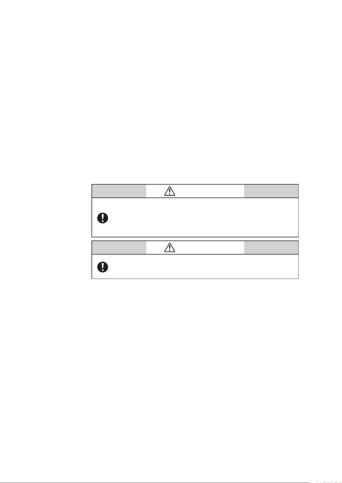
WARNING
Use this product under the conditions as defined in the specifications (e.g., protection against explosion, pressure rating, temperature,
humidity, voltage, vibration, shock, mounting direction, and atmosphere) to avoid failure of the device or harmful physical effects such
as fire damage.
WARNING
In case of the installation in the hazardous area, select the explosionprotected apparatus. Do not use the non-explosion-protected apparatus in the hazardous area.
3-2
Page 29
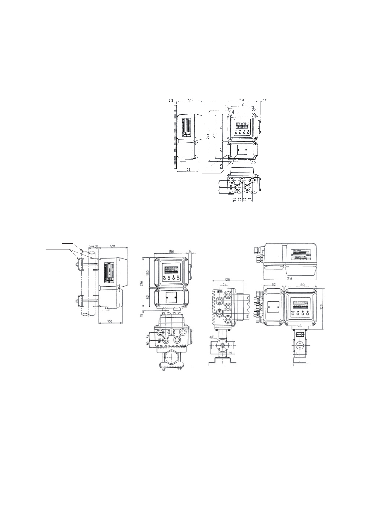
3.2 Installation of transmitter
Mounting bracket
Material: SPCC
(Zinc plating)
2B-pipe
2B-pipe mounting
Installation of transmitter
Basic mounting methods
The transmitter can be mounted in three ways—integrated mounting with the
flowtube, wall-mounting, and 2B-pipe mounting
Mounting plate
Terminal box
Tag number plate
Figure3-1 Wall-mounting of transmitter
Figure3-2 2B-pipe mounting of transmitter and Integrated mounting
3-3
Page 30
Electrical wiring (1)
DO NOT wire with wet hands. DO NOT wire while the circuit is alive. It may cause electrical
shock.
ELECTRIC SHOCK HAZARD! Turn the power supply OFF before opening the transmitter
cover.
Wiring of the device should be done by the expert from safety perspective.
Wire the cables to the correct terminal. Incorrect wiring may damage the device or cause
the fume of the device.
Connect the correct power supply. Incorrect power supply may damage the device or
cause the fume of the device.
Be sure to properly ground the device. Improper grounding may cause the output errors
DO NOT give impact to the device. It may cause the damage of the device.
WARNING
CAUTION
Be sure to use the power supply with the overcurrent protection function.
Be sure proper wiring. Incorrect wiring may cause the damage of the device.
Be sure to properly tighten the terminal cover on the terminal box so that water does not
penetrate in the terminal.
DO NOT connect AC power supply to the DC power supply model. The wrong power supply damages the device.
Turn off the Fieldbus power supply before connecting the Fieldbus cable to the transmitter. The transmitter or the Fieldbus power supply can be damaged. This type of damage is
not covered by Azbil Corporation’s warranty.
Be sure to plug all unused conduit connections with a water tight plug.
In case that a remote model is installed in a ship, the cables between the transmitter and
flowtube must be covered with a flexible metal conduit.
Switch the control equipment to manual control before terminating the device operation and shutting off the output to the control equipment. This action prevents the power
shut-off from directly affecting the control equipment.
Introduction
The electromagnetic flowmeter needs to be connected to the main power supply (AC or
DC 24 V) for proper operation.
The following items are described in relation to the electrical wiring of the electromagnetic
flowmeter.
3-4
Page 31

- Connection points on the main unit of the electromagnetic flowmeter
- Terminal layout
- Transmitter terminal table
- Cables between flowtube and transmitter
- Cable specifications
- Connection between flowtube and transmitter
- Selection of wiring cable
- Installation of wiring cable
- Connection to the Fieldbus output
Note:
- Do not directly connect the AC power supply to the main unit of the electromagnetic
flowmeter if the main power supply is designed to be 24 V DC. AC power supplied
to the main unit of the electromagnetic flowmeter causes irreversible damage in the
internal measurement circuit.
Connection points on the main unit of the electromagnetic flowmeter
Figure 3-4 presents the terminal block of the main unit of the electromagnetic flowmeter.
WARNING
· In wiring, turn off the power before opening the cover to avoid electric shock.
· DO NOT perform wiring work when current is being applied. Doing so may
cause electric shock.
Note:
- Properly align the wiring position as indicated. Improper wiring can damage the
device.
- Especially, check the wiring position of the power lines again as they carry a high
capacity current.
3-5
Page 32

Terminal layout
Figure3-3 Terminal layout of remote transmitter
Integral transmitter: Terminal layout
Unlike a remote transmitter, an integral transmitter does not use the terminals X, Y, SB,
SA, A, B, C, and E. These terminal symbols are thus erased from the layout.
DC-24V transmitter: Terminal wiring diagram
The power terminal of the DC-24V remote transmitter is indicated as POWER DC
24V. Check carefully if the polarity is positive or negative.
Transmitter terminal table
Terminals for a remote transmitter Terminals for an integral transmitter
Symbol Description Symbol Description
A
B -
C
SA N
SB
FIELDBUS
X
Y
POWER AC
E Not used
Flow signal input
+
Fieldbus output
-
Excitation output
L
N
Power supply
Grounding
(grounding
resistance must be
FIELDBUS
POWER AC
<100)
+
Fieldbus output
L
Power supply
Grounding
(grounding resistance
must be <100)
3-6
Page 33

Electrical wiring (2)
Cable length (m)
Cable length (m)
Cables between flowtube and transmitter
Please use a special cable (MGA12W) designated for connecting the flowtube and
transmitter.
Select a signal cable (Azbil’s special cable or a commercially-available shielded cable)
depending on the fluid conductance, cable length, and the diameter of the flowtube. Refer
to the figure below.
- Range where Azbil’s special cable can be used: A and B
- Range where a commercially-available cable can be used: Only A
2.5mm and 5mm Diameter Cable >10mm Diameter Cable
B. Usage range of dedicated
cable, model MGA12W
A. Usage range of
commercially
available cable
Fluid Conductivity (µs/cm)
B. Usage range
of dedicated
cable, model
MGA12W
Fluid Conductivity (µs/cm)
Figure3-4 Relationship between the fluid conductance and cable length
Specifications of cables between flowtube and transmitter
Cable (between remote flowtube and transmitter):
Length: Maximum 300 m (depends on the fluid conductance)
Outer diameter: φ 10–12 mm
2
Signal cable: Special cable (diameter of 11.4 mm, 0.75 mm
), or an equivalent among
commercially-available shielded cables (e.g., CVVS, CEEV)
Excitation cable: Special cable (φ 10.5 mm, 2 mm2), or an equivalent among
commercially-available shielded cables (e.g., CVV)
Note:
- Always use a shielded cable as a signal cable.
A. Usage range of
commercially
available cable
3-7
Page 34

Signal cable
Designed for an M4 screw
Conductive wire
(Model: MGA12W)
Cable termination on the owtube side
Cable termination on the transmitter side
Designed for an M4 screw
Designed for an M4 screw
Designed for an M4 screw
Designed for an M4 screw
Flowtube
side
(type code A)
(type code B)
Cable termination on the owtube side
(type code B)
Transmitter
side
Flowtube
side
Flowtube
side
Cable termination on the Zener barrier side
Flowtube
side
Flowtube
side
Zener barrier side
Zener barrier side
Designed for an M4 screw
Designed for an M3 screw
(type code E)
Designed for an M3 screw
(type E)
Designed for an M3 screw
Designed for an M3 screw
(type code E)
Designed for an M4 screw
Designed for an M4 screw
Cable termination on the Zener barrier side
(type code D)
Flowtube
side
(type code E) (type code C)
Flowtube
side
(type code E)
Outer sheath
Inner sheath
Inner shield
Outer shield
Cable termination on the transmitter side
Zener barrier side
Zener barrier side
Conductive tube
Insulator
Note) Remove the conductive tubes (black) of conductive cables for terminals A and B up
to the edge s of the inner shields.
Figure3-5 Structural drawing of signal cable
3-8
Page 35

Excitation cable
Designed for an M4 screw
(Model: MGA12W)
Designed for an M4 screw
Insulator
60
Flowtube
side
Transmitter
side
70
Designed for an M4 screw
70L60
Designed for an M4 screw
Designed for an M4 screw
Designed for an M4 screw
Cable termination on the owtube side
Black
White
Flowtube
side
50
50
(Model code: A)
Black
White
Flowtube
side
50
50
(Model code: A)
Black
White
Black
White
Flowtube
side
Flowtube
side
60
39
(Model code: B)
60
39
(Model code: B)
Sheath
Insulator
Conductive wire
Fabric tape
Figure3-6 Structural drawing of excitation cable
3-9
Page 36

Electrical wiring (3)
Dedicated cable model MGA12W
Commercially available cable
Connection between flowtube and transmitter
Detector
A
Signal cable
model MGA12W
Signal cable 2-core
Single shielded cable
Converter
SA
A
C
B
X
Y
Excitation cable
model MGA12W
Signal cable 2-core
Single shielded cable
Detector
A
C
B
X
Y
Excitation cable
Figure3-7 Connection between flowtube and transmitter
C
B
SB
X
Y
Converter
A
C
B
X
Y
3-10
Page 37

4. Startup and Shutoff
Overview
This chapter describes the procedure for starting up the device and performing zero
adjustment.
Follow the instructions in this chapter when you start up and operate the device for the
first time.
Zero adjustment can be made in one of the following ways:
Using the device’s LUI
Using a fieldbus configurator to communicate with the device
This chapter describes how to perform zero adjustment using the local user interface (LUI).
Refer to Chapter 5 for the alternative method using Fieldbus communication.
4.1 Startup
Start up the device
Procedure
Start up the electromagnetic flowmeter according to the following procedure.
Step Procedure
Make sure that the flowtube of the electromagnetic flowmeter is properly
1
connected to the piping.
Make sure that the flowtube and transmitter of the electromagnetic flowmeter are
2
securely wired.
Fill the flowtube of the electromagnetic flowmeter with a measurement fluid and
3
pause the flowtube.
Check for any fluid leakage from the flange, to which the flowtube of the
4
electromagnetic flowmeter is attached.
5 Apply current to the transmitter of the electromagnetic flowmeter.
Make sure that the LUI display is turned on.
Image
6
This completes the startup of the electromagnetic flowmeter.
. . . . .
4-1
Page 38

4.2 Steps before measurement
m3/h
m3/h
m3/h
m3/h
m3/h
Setting up flowtube data
Getting started
Select and configure the constant of the flowtube used in combination with the
transmitter, flowtube type, and diameter.
Default settings
The settings of EX 300.0, MGG, and DIA 050.0 are applied when no flowmeter is specified
for the combined use with the transmitter.
Note:
If you have purchased a combination set including a transmitter and a flowtube, the
flowtube data are already configured by real current calibration. Note that any change
will result in an output error from the flowmeter. Refer to Table 4-1.
Improper setting of flowtube information can result in
output errors from the flowmeter.
Step Procedure Screen
WARNING
Follow the procedure for entering BASIC SETUP MODE
1
to display the screen for setting up the flowtube data.
Touch the key to set up the constant for the flowtube.
Use the and keys to enter the value for the EX section
2
which is printed on the name plate of the flowtube to be
used in combination with the transmitter.
Next, touch the key to select the flowtube type.#Use
the and keys to select the MODEL number which is
3
printed on the name plate of the flowtube to be used in
combination with the transmitter.
Next, touch the key to select the diameter.#Use the
4
and keys to select the diameter of the flowtube used in
combination with the transmitter.
Touch the key to move the cursor underneath the *
5
mark.
4-2
Page 39

Zero adjustment
m3/h
m3/h
m3/h
m3/h
m3/h
m3/h
Getting started
Make sure to perform zero adjustment after starting up the device. There are three ways to
do so.
Using the device’s LUI
Using the parameter list by communicating with the device
Using the menu by communicating with the device
Adjust the measured instantaneous flow rate value to zero when the fluid inside the
flowtube is sitting still.
Note:
Zero adjustment is extremely important for ensuring accurate measurement of flow
rate. Make sure to perform this adjustment when you first operate the device.
Before performing zero adjustment, make sure that Class D grounding is reliably
performed with the flowtube and that the flowtube is filled with a measurement fluid
which is sitting still.
Zero adjustment is possible when the flow velocity falls below 0.2 m/s. Wait until the
fluid comes to a complete rest (a flow velocity of 0.0 m/s) to avoid output errors.
Zero adjustment requires O/S to be selected for the Actual MODE in Flow Transducer
Block.
Configure the setting from the host system in advance.
Step Procedure Screen
Touch the MODE key for 3 seconds or longer.
Note: The screen as shown on the right is displayed only
1
for 8 seconds. Perform the following operations within 8
seconds. Touch the
Touch the
key to move the cursor underneath YES and
key four times.
touch the ke y.
2
is displayed before the screen
switches to the one shown on the
right in 2 seconds.
Touch the
3
the right.
Touch the key once to move the cursor underneath
4
READY.
key once to display the screen as shown on
Touch the key to start zero adjustment. During the
adjustment, the value of 0.0 blinks for displaying the large
7-segment flow rate. Once the adjustment is complete,
5
the value stops blinking and the screen returns from ON
to READY.
This period is about 30 seconds.
At the very end, make sure to touch the MODE key to
6
complete the adjustment.
4-3
Page 40

Checking the operation of Fieldbus
Check to see if the device operates properly with Fieldbus.
Prior to operating Fieldbus, the DD file (device description) and the CF file (capability) of
the device need to be copied to the host.
Download the DD file and CF file from the official website of the FieldComm Group.
Operation of Fieldbus requires the following settings in the host.
Ensure that PD_TAG and NODE_ADRS can be set up by configuring the following
settings.
1) Network parameter settings for link active scheduler (LAS)
Symbol Parameter name Description and setting value
V(ST) Slot time Set a value of 5 or greater.
V(MID) Gap between minimum frames Set a value of 10 or greater.
V(MRD) Maximum response delay time
V(FUN)
V(NUN) Total number of unpolled nodes
The number of the first unpolled
node
Set the value so that V(MRD)
V(ST) is 20 or greater.
Set the value immediately next to
the address used by the host. Set
a value of 12 or greater in 16-bit
representation.
The number represents the range
of unused addresses. Set the value
of the minimum address used by
the device in the work site minus
the value of V(FUN).
1) Checking PD_TAG (physical device tag) and address
Parameter name Parameter name Setting value
PD_TAG Physical device tag
NODE_ADRS Node address
The same address setting as another device cannot be selected for NODE_ADRS. (Such an
entry is changed into the default address [0xF8–0xFB])
Assign a different address for each unit.
Up to 32 ASCII
characters
Set the minimum
address of the BASIC
device in hexadecimal
notation and F7 or less
Data when shipped
from the factory
Specified by customers
Hexadecimal notation
and F8
4-4
Page 41

4.3 Shutoff
CAUTION
· Make sure to switch the controller to manual control mode in order to
shut off the device and stop the output to the controller.
This safeguards the controller from direct impacts caused by the suspended output from the device.
· Do not turn off the power within 60 seconds of any data being rewritten using the LUI or another communication method, to avoid possible errors in saving the data.
Procedure
Take the following procedure to shut off the device.
Step Procedure
1 Switch the controller of the device you want to shut off to manual control mode.
2 Turn off the power of the device.
4-5
Page 42

4-6
Page 43

5. Basic Settings by Fieldbus Communication
Overview
This chapter outlines zero adjustment as an operation performed using Fieldbus
communication, each Transducer block, as well as basic parameter settings.
Some parameters require O/S to be selected for the Block MODE parameter in order to
change the settings.
Mode parameters can be switched with MODE_BLK in each block.
In order to use each block after the settings are changed, select AUTO for MODE-BLK.
Note
- The device supports Version 3.8 or later versions of 475.
Version 3.6 or earlier versions cannot properly display some parameters.
- The device supports host authentication, HTK 6.1.a or later versions, and Standard
Dictionary 3.70 or later versions.
Other versions may fail to display some parameters.
- Some parameters may not be properly displayed when some hosts are used.
- METHOD may not work with some hosts.
In such cases, access the parameter from the parameter list to configure the settings.
5-1
Page 44

5.1 Fieldbus communication menu
There are four types of menu structures for Fieldbus communication depending on the
host being used.
This section describes the device menu for communicators.
- Device menu for communicators
This menu displays parameters such as setup and adjustment of the positioner.
A host supporting the device menu can display this menu. (Example: 475 Field
Communicator by Emerson)
- Block menu for communicators
A communicator capable of Fieldbus communication can display this block menu. A
menu prepared for each block displays parameters such as setup and adjustment of the
positioner. (Example: 475 Field Communicator by Emerson)
- Block menu for PCs
A compatible host (PC) can display this block menu. A menu prepared for each block
displays parameters such as setup and adjustment of the positioner. (Example: Azbil's
device management system - InnovativeField Organizer)
- Parameter list
All parameters are displayed by block.
Appendix C presents a list of parameters for Flow Transducer Block, Resource Block,
and Display Transducer Block.
5-2
Page 45

5.2 Zero adjustment
Getting started
Once the device has started up, make sure to perform zero adjustment in one of the
following three ways.
Adjust the measured instantaneous flow rate value to zero when the fluid inside the
flowtube is sitting still.
Note:
- Zero adjustment is extremely important for ensuring accurate measurement of flow
rate. Make sure to perform this adjustment when you first operate the device.
- Before performing zero adjustment, make sure that Class D grounding is reliably
performed with the flowtube and that the flowtube is filled with a measurement fluid
which is sitting still. Zero adjustment is possible when the flow velocity falls below 0.2
m/s. Make sure to wait until the fluid comes to a complete rest (a flow velocity of 0.0
m/s) to avoid output errors.
- Zero adjustment requires O/S to be selected for the Actual MODE in Flow Transducer
Block.
Configure the setting from the host system in advance.
Accessing the option from the menu
Note: Use METHOD in the menu to perform zero adjustment. METHOD may not
operate with some hosts.
In such cases, perform zero adjustment by accessing the option through the
parameter list.
- Device menu for communicators
Perform zero adjustment by selecting Device Maintenance Auto Zero Adjustment
(METHOD).
- Block menu for communicators or Block menu for PCs
Perform zero adjustment by selecting FLOW Transducer Block Block Maintenance
Auto Zero Adjustment (METHOD).
Accessing the option from the parameter list
Set TARGET in MODE_BLK of FLOW Transducer Block to O/S (Out of Service).
1
Set “1” (Execute) to AUTO_ZERO_CALIBRATION_CMD in FLOW Transducer
Block.
Zero adjustment starts.
2
Set “4” (Canceled) to AUTO_ZERO_CALIBRATION_CMD in FLOW Transducer
Block in order to cancel zero adjustment.
Execution results of automatic zero adjustment can be checked at
MANUAL_ZERO_CALIBRATION_CMD in FLOW Transducer Block.
3
While “1” (Executing) is displayed during execution of zero adjustment, “2” (Success) is
displayed when zero adjustment is completed successfully.
For flow measurement, set TARGET of Transducer Block in FLOW Transducer Block to
4
AUTO.
5-3
Page 46

5.3 Basic settings
Sensor value
Flow Transducer Block
Overview of function
Flow Transducer Block enables calculation of flow velocity, volume flow rate, and mass
flow rate based on the sensor outputs of the electromagnetic flowmeter.
The calculated volume flow rate and mass flow rate are output to AI Function Block
and TOT Function Block. A flow switch is prepared for turning the transducer on or off
depending on the volume flow rate and mass flow rate. The value assigned to the flow
switch is output to DI Function Block.
Function Block diagram
The following diagram shows the configuration of Flow Transducer Block.
Calculation function
Self-diagnosis history
Adjustment function
SENSOR_VALUE (ow velocity)
Conguration function
PRIMARY_VALUE
(volume ow rate)
SECONDARY_VALUE
(mass ow rate)
FLSW1_VALUE
FLSW2_VALUE
Figure5-1 Function Block diagram
Parameters
Major parameters for Flow Transducer Block are described as follows.
Refer to the attached Parameter List for more descriptions of parameters.
Output
SENSOR_VALUE
Indicates the flow velocity (m/s) of the measurement fluid.
PRIMARY_VALUE
Indicates the volume flow rate and the status.
Channel 1 corresponds to this parameter.
Select 1 for CHANNEL of Function Block you want to use in order to connect to AI
Function Block or TOT Function Block.
SECONDARY_VALUE
Indicates the mass flow rate and the status.
Channel 2 corresponds to this parameter.
Select 2 for CHANNEL of Function Block you want to use in order to connect to AI
Function Block or TOT Function Block.
FLSW_1_VALUE_D
Indicates the output value of Flow Switch 1 and the status.
Channel 100 corresponds to this parameter.
Select 100 for CHANNEL of Function Block you want to use in order to connect to DI
Function Block.
FLSW_2_VALUE_D
Indicates the output value of Flow Switch 2 and the status.
Channel 101 corresponds to this parameter.
Select 101 for CHANNEL of Function Block you want to use in order to connect to DI
Function Block.
Settings
PRIMARY_VALUE_RANGE
5-4
Page 47

Indicates setting values for the upper and lower range limits, unit, and the position of
the decimal point for the volume flow rate.
The unit for the flow rate must be identical to the unit assigned for XD_SCALE in AI
Block.
Refer to Table 5-1 for the units that can be set up.
SECONDARY_VALUE_RANGE
Indicates setting values for the upper and lower range limits, unit, and the position of
the decimal point for the mass flow rate.
The unit for the flow rate must be identical to the unit assigned for XD_SCALE in AI
Block.
Refer to Table 5-2 for the units that can be set up.
DENSITY_CONSTANT
Fluid density setup
The assigned value is applied to the calculation of SECONDARY_VALUE (mass flow
rate).
FLOWTUBE_SIZE
Flowtube diameter setup
FLOWTUBE_TYPE
Flowtube type setup
EMPTY_PIPE_DETECTOR
Indicates whether the empty detection function is enabled or disabled.
Calculation function
DAMPING_CONSTANT
A damping constant can be set up when a tiny variation component needs to be cut off
from the measured instantaneous flow rate value.
PRIMARY_VALUE_LOW_FLOW_CUT
A low cut-off threshold can be set for the volume flow rate.
Available range is 0 to 10% (percentage of PRIMARY_VALUE_RANGE.EU100).
SECONDARY_VALUE_LOW_FLOW_CUT
A low cut-off threshold can be set for the mass flow rate.
Available range is 0 to 10% (percentage of SECONDARY _VALUE_RANGE.EU100).
Adjustment function
AUTO_ZERO_CALIBRATION_CMD
This command executes automatic zero adjustment.
Run this command in order to perform zero adjustment when the fluid is filled
and sitting still in the flowtube.
GAIN_CALIBRATION_CMD
This command executes gain adjustment of the transmitter.
Run this command in order to perform zero adjustment of the transmitter using a
calibrator, etc.
Self-diagnosis history
FLOW_TB_STATUS_RECORD_1–10
Saves self-diagnosis history.
5-5
Page 48

Table 5-1. Units that can be set up for volume flow rate
Unit of
volume
flow rate
3
cm
3
m
cm3/d (1514) cm3/h (1513) cm3/min (1512) cm3/s (1511)
m3/d (1350) m3/h (1349) m3/min (1348) m3/s (1347)
d h min s
L L/d (1354) L/h (1353) L/min (1352) L/s (1351)
bbl bbl/d (1374) bbl/h (1373) bbl/min (1372) bbl/s (1371)
mgal/h (1457)
gal/h (1364)
kgal/h (1458)
mImpGal_h (1472)
ImpGal/h (1369)
kImpGal/h (1473)
gal
ImpGal
mgal/d (1461)
gal/d (1365)
kgal/d (1462)
mImpGal_d (1476)
ImpGal/d (1370)
kImpGal/d (1477)
Unit of time
mgal/min (1453)
GPM (1363)
kgal/min (1454)
mImpGal_min (1468)
ImpGal/min (1368)
kImpGal/min (1469)
mgal/s (1459)
gal/s (1362)
kgal/s (1450)
mImpGal_s (1464)
ImpGal/s (1367)
kImpGal/s (1465)
Table 5-2. Units that can be set up for mass flow rate
Unit of
volume
flow rate
g
g/d (1321)
kg/d (1325)
d h min s
g/h (1320)
kg/h (1324)
t t/d (1329) t/h (1328) t/min (1327) t/s (1326)
lb lb/d (1333) lb/h (1332) lb/min (1331) lb/s (1330)
Unit of time
g/min (1319)
kg/min (1323)
g/s (1318)
kg/s (1322)
5-6
Page 49

Display Transducer Block
Overview of function
Display Transducer Block controls the display of measurement values and alarm
indication in the local user interface (LUI).
Input and output signal values for function blocks installed in the device can be displayed,
such as OUT of AI Block and PRIMARY_VALUE and SECONDARY_VALUE of Flow
Transducer Block.
Parameter
Major parameters of Display Transducer Block are described as follows.
Refer to the attached Parameter List for more descriptions of parameters.
DISPLAY_PARAM_SELECTION
Select the parameter you want to display from among the parameters configured in the
display setting 1 to 4.
Up to four parameters can be displayed in chronological order.
If all of the parameters for 1 to 4 are unselected, O/S is set for MODE_BLK._Actual in
Display Transducer Block.
DISPLAY_INFO_SELECTION
Adjunct data (tag, status, and unit) that are commonly assigned for parameters in the
display setting 1 to 4 can be configured. Factory default is 0x07 (Tag, Unit, Status
are all selected)
For example, if not displaying Tag and Status, and displaying only Unit, change the
setting to 0x02.
If all the adjunct data are unselected, O/S is set for MODE_BLK._Actual in Display
Transducer Block.
DISPLAY_CYCLE
The cycle for updating the display can be set in units of seconds, in a range from 1 to 10
seconds. Factory default is 0x05(5 sec).
BLOCK_TAG_SELECTION_n
Enter BLOCK_TAG for the block to which the parameter is to be displayed in the
display setting n. Enter the BLOCK_TAG of the block that has the parameters to be
displayed into BLOCK_TAG_SELECTION_n. If an incorrect value is entered, the block
cannot be identified and display settings cannot be set up.
PARAM_SELECTION_n
Select a parameter you want to display in the display setting n.
Available values are presented in Table 5-3.
*1
*2
*2
Note: When writing is not possible for BLOCK_TAG_SELECTION_n (n=1 to 4), or
PARAMETER_SELECTION_n (n=1 to 4), switch the settings of RB FEATURE_SEL
Bit_12 (Deferral of Inter-Parameter Write Checks) to ON (enabled).
DISPLAY_TAG_n
*2
Enter the text you want to display in the indicator as a tag for the display setting n.
Up to 16 characters can be entered.
5-7
Page 50

UNIT_SELECTION_n
*2
You can select whether the parameter in display setting n will be displayed using the
unit associated with it or another desired unit.
Select Auto (0) in order to display the parameter with the associated unit as assigned
for the displayed value, and select Custom (1) in order to display the parameter with
another desired unit.
Please refer to the parameter list, which includes the display parameter, and section in
Table 5-4, “LUI Display Unit String.”
CUSTOM_UNIT_n
*2
Enter the text you want to display as the unit.
This parameter is displayed only when Custom is selected in UNIT_SELECTION_n.
Up to 16 characters can be entered for CUSTOM_UNIT_n.
*1 If changing the display time, change the parameter setting.
*2 If changing the display detail from the factory default PV value of the Flow Transducer Block to
other parameter, change these parameters.
Regular Display
With the factory default setting, the PV value of Flow Transducer Block is displayed.
With the factory default setting, it gets displayed periodically according to the following
sequence.
Seq. No. 1 2 3
Main Disp.
Aux. Disp
DisplayTime
FTB:PV value FTB:PV value FTB:PV value
PRIMARY_VALUE (Specified Unit) (Status)
5 5 5
For example, if you wish to change the display detail to Out value of AI Function Block,
1. Set AI_FB_01 in BLOCK_TAG_SELECTION_1. (AI_FB_01 of Block Tag is
the factory default value. If it has been changed since factory shipment, set this
modified value)
2. Verify that BLOCK_TYPE_SELECTION_1 is now AI Function Block(0x0101).
3. Select 8:OUT for PARAM_SELECTION_1
4. For example, change DISPLAY_TAG_1, which is the tag to be displayed, to OUT.
For other displayable parameters, please refer to Table 5-3.
Note: If you change the Block Tag of the block that you are trying to set the display for, the
setting will not get properly implemented.
If you had changed the Block Tag, turn the device power off and then on again, or
write “4{Restart Processor}” to Resource Block’s RESTART section and then restart
your device.
5-8
Page 51

Several Parameter Display
Display Transducer Block can display a maximum of 4 parameters sequentially and
periodically. This section will explain the setting of displaying two parameters as an
example.
This explains how to set it to display the PV value of Flow Transducer Block and OUT
value of AI Function Block periodically.
- The factory default setting sets it so that it only displays the PV value of Flow
Transducer Block. In addition, if adding OUT value of AI Function Block as the second
parameter, enable bit1:Parameter 2 of the DISPLAY_PARAM_SELECTION.
DISPLAY_PARAM_SELECTION will change from the factory default 0x01 to 0x03.
- Next you will set BLOCK_TAG_SELECTION_2 to AI_FB_01. Verify that BLOCK_
TYPE_SELECTION_2 is now set to 0x0101 AI Function Block (AI_FB_01 of Block
Tag is the factory default value. If it has been changed since factory shipment, set this
modified value).
- Select 8:OUT for PARAM_SELECTION_2.
- Set the DISPLAY_TAG_2, a display tag, to OUT for example.
By conducting the above setting, it gets displayed periodically according to the following
sequence.
Seq. No. 1 2 3 4 5 6
Main Disp.
Aux. Disp
DisplayTime
FTB:PV
value
PRIMARY_
VALUE
5 5 5 5 5 5
FTB:PV
value
(Specified
Unit)
FTB:PV
value
(Status) OUT
AI:OUT
value
AI:OUT
value
(Specified
Unit)
AI:OUT
value
(Status)
Set the following to display the third parameter along with the above.
DISPLAY_PARAM_SELECTION: 0x07 (enable bit2:Parameter 3 as well)
BLOCK_TAG_SELECTION_3: set the Block Tag to be displayed
PARAM_SELECTION_3: select the parameter to be displayed
DISPLAY_TAG_3: set the Tag to be displayed
Set the following to display the fourth parameter as well.
DISPLAY_PARAM_SELECTION: 0x0f (enable bit3:Parameter 4 as well)
BLOCK_TAG_SELECTION_4: set the Block Tag to be displayed
PARAM_SELECTION_4: select the parameter to be displayed
DISPLAY_TAG_4: set the Tag to be displayed
Please refer to Appendix B for detail on Display Transducer Block parameters.
Note: If you change the Block Tag of the block that you are trying to set the display for, the
setting will not get properly implemented.
If you had changed the Block Tag, turn the device power off and then on again, or
write “4{Restart Processor}” to Resource Block’s RESTART section and then restart
your device.
5-9
Page 52

Status Display
Please refer to Table 5-5 for the status displayed by the string part.
Alarm Display
When an alarm is activated, the alarm display strings of Table 5-6 will get periodically
displayed.
Irregular Display
During OOS and main board communication error, the regular display will be switched to
irregular display.
OOS Display
When Display Transducer Block is OOS (Out Of Service), it will display the following.
Main Disp.
Aux. Disp
(upper)
(lower)
DISPLAY OFF
DISP TB O/S
Main Board Communication Error Display
When a main board communication error occurs inside the transmitter, the following
gets displayed.
Main Disp.
Aux. Disp
(upper)
(lower)
HW ERROR
COMM ERROR
Table 5-3 Display Transducer Block Displayable Parameter List
Block ProfileNumber Parameter Index Range Index
FlowTB 0x0113 PRIMARY_VALUE 15 PRIMARY_VALUE_RANGE 16
SECONDARY_VALUE 18
DiagTB 0x8018 SCALE_LEVEL 15 SCALE_LEVEL_RANGE 16
AI 0x0101 OUT 8 OUT_SCALE 11
PID 0x0108 OUT 9 OUT_SCALE 11
IN 15 PV_SCALE 10
CAS_IN 18 PV_SCALE 10
BKCAL_IN 27 OUT_SCALE 11
BKCAL_OUT 31 PV_SCALE 10
RCAS_IN 32 PV_SCALE 10
ROUT_IN 33 OUT_SCALE 11
RCAS_OUT 35 PV_SCALE 10
ROUT_OUT 36 OUT_SCALE 11
TRK_VAL 39 TRK_SCLAE 37
FF_VAL 40 FF_SCALE 41
AR 0x0127 OUT 8 OUT_RANGE 11
IN 14 PV_SCALSE 10
IN_LO 15 PV_SCALSE 10
IN1 16 PV_SCALSE 10
IN2 17 PV_SCALSE 10
IN3 18 PV_SCALSE 10
TOTALIZER 0x0144 OUT 9 OUT_RANGE 12
PRESET_IN 20 XD_RANGE 11
SECONDARY_VALUE_
RANGE
19
5-10
Page 53

Table 5-4 LUI Display Unit String List
Unit Code Unit String Displayed in LUI Description
1000 K Kelvin
1001 degC degree Celsius
1002 degF degree Fahrenheit
1003 degR degree Rankine
1034 m3 cubic meter
1036 cm3 cubic centimeter
1038 L liter
1048 gal US gallon
1049 ImpGal Imperial gallon
1051 bbl barrel
1088 kg kilogram
1089 g gram
1092 t metric ton
1094 lb pound (mass)
1130 Pa pascal
1131 GPa gigapascal
1132 Mpa megapascal
1133 kPa kilopascal
1134 mPa millipascal
1135 uPa micropascal
1136 hPa hectopascal
1137 bar bar
1138 mbar millibar
1139 torr torr
1140 atm atmospheres
1141 psi pounds per square inch
1142 psia pounds per square inch absolute
1143 psig pounds per square inch gauge
1144 gcm2 gram per square centimeter
1145 kgcm2 kilogram per square centimeter
1146 inH2O inches of water
1147 inH2O_4C inches of water at 4°C
1148 inH2O_68F inches of water at 68°F
1149 mmH2O millimeters of water
1150 mmH2O_4C millimeters of water at 4°C
1151 mmH2O_68F millimeters of water at 68°F
1152 ftH2O feet of water
1153 ftH2O_4C feet of water at 4°C
1154 ftH2O_68F feet of water at 68°F
1155 inHg inches of mercury
1156 inHg_0C inches of mercury at 0°C
1157 mmHg millimeters of mercury
1158 mmHg_0C millimeters of mercury at 0°C
1318 g/s gram per second
1319 g/min gram per minute
1320 g/h gram per hour
1321 g/d gram per day
1322 kg/s kilogram per second
1323 kg/min kilogram per minute
1324 kg/h kilogram per hour
1325 kg/d kilogram per day
1326 t/s metric ton per second
1327 t/min metric ton per minute
1328 t/h metric ton per hour
1329 t/d metric ton per day
1330 lb/s pound per second
5-11
Page 54

Unit Code Unit String Displayed in LUI Description
1331 lb/min pound per minute
1332 lb/h pound per hour
1333 lb/d pound per day
1334 STon/s short ton per second
1335 STon/min short ton per minute
1336 STon/h short ton per hour
1337 STon/d short ton per day
1338 LTon/s long ton per second
1339 LTon/min long ton per minute
1340 LTon/h long ton per hour
1341 LTon/d long ton per day
1342 % percent
1347 m3/ s cubic meter per second
1348 m3/min cubic meter per minute
1349 m3/ h cubic meter per hour
1350 m3/ d cubic meter per day
1351 L/s liter per second
1352 L/min liter per minute
1353 L/h liter per hour
1354 L/d liter per day
1355 ML/d megaliter per day
1356 CFS cubic feet per second
1357 CFM cubic feet per minute
1358 CFH cubic feet per hour
1359 ft3/d cubic feet per day
1360 SCFM standard cubic feet per minute
1361 SCFH standard cubic feet per hour
1362 gal/s US gallon per second
1363 GPM US gallon per minute
1364 gal/h US gallon per hour
1365 gal/d US gallon per day
1366 Mgal/d mega US gallon per day
1367 ImpGal/s Imperial gallon per second
1368 ImpGal/min Imperial gallon per minute
1369 ImpGal/h Imperial gallon per hour
1370 ImpGal/d Imperial gallon per day
1371 bbl/s barrel per second
1372 bbl/min barrel per minute
1373 bbl/h barrel per hour
1374 bbl/d barrel per day
1449 mgal/s milli US gallon per second
1450 kgal/s kilo US gallon per second
1451 Mgal/s mega US gallon per second
1453 mgal/min milli US gallon per minute
1454 kgal/min kilo US gallon per minute
1455 Mgal/min mega US gallon per minute
1457 mgal/h milli US gallon per hour
1458 kgal/h kilo US gallon per hour
1459 Mgal/h mega US gallon per hour
1461 mgal/d milli US gallon per day
1462 kgal/d kilo US gallon per day
1463 Mgal/d mega US gallon per day
1464 mImpGal/s milli imperial gallon per second
1465 kImpGal/s kilo imperial gallon per second
1466 MImpGal/s mega imperial gallon per second
1468 mImpGal/min milli imperial gallon per day
1469 kImpGal/min kilo imperial gallon per day
5-12
Page 55

Unit Code Unit String Displayed in LUI Description
1470 MImpGal/min mega imperial gallon per day
1472 mImpGal/h milli imperial gallon per hour
1473 kImpGal/h kilo imperial gallon per hour
1474 MImpGal/h mega imperial gallon per hour
1476 mImpGal/d milli imperial gallon per day
1477 kImpGal/d kilo imperial gallon per day
1478 MImpGal/d mega imperial gallon per day
1482 Mbbl/s megabarrel per second
1486 Mbbl/min megabarrel per minute
1490 Mbbl/h megabarrel per hour
1494 Mbbl/d megabarrel per day
1496 mm3/s cubic millimeter per second
1497 km3/s cubic kilometer per second
1498 Mm3/s cubic megameter per second
1500 mm3/min cubic millimeter per minute
1501 km3/min cubic kilometer per minute
1502 Mm3/min cubic megameter per minute
1504 mm3/h cubic millimeter per hour
1505 km3/h cubic kilometer per hour
1506 Mm3/h cubic megameter per hour
1508 mm3/d cubic millimeter per day
1509 km3/d cubic kilometer per day
1510 Mm3/d cubic megameter per day
1511 cm3/s cubic centimeter per second
1512 cm3/min cubic centimeter per minute
1513 cm3/h cubic centimeter per hour
1514 cm3/d cubic centimeter per day
1518 kL/min kiloliter per minute
1519 kL/h kiloliter per hour
1520 kL/d kiloliter per day
1522 Nm3/s Normal cubic meter per second
1523 Nm3/min Normal cubic meter per minute
1524 Nm3/h Normal cubic meter per hour
1525 Nm3/d Normal cubic meter per day
1527 Sm3/s Standard cubic meter per second
1528 Sm3/min Standard cubic meter per minute
1529 Sm3/h Standard cubic meter per hour
1530 Sm3/d Standard cubic meter per day
1532 NL/s Normal liter per second
1533 NL/min Normal liter per minute
1534 NL/h Normal liter per hour
1535 NL/d Normal liter per day
1537 SL/s Standard liter per second
1538 SL/min Standard liter per minute
1539 SL/h Standard liter per hour
1540 SL/d Standard liter per day
1589 mL/min milliliters per minute
1617 ML/h megaliter per hour
1618 ML/min megaliter per minute
1619 kL/s kiloliter per second
1620 kft3/ d cubic kilofeet per day
1621 kCFH cubic kilofeet per hour
1622 kCFM cubic kilofeet per minute
1623 kCFS cubic kilofeet per second
1624 mft3/ d cubic millifeet per day
1625 mCFH cubic millifeet per hour
1626 mCFM cubic millifeet per minute
5-13
Page 56

Unit Code Unit String Displayed in LUI Description
1627 mCFS cubic millifeet per second
1648 kgal kilogallon
1649 kImpGal kilo-imperial gallon
1653 Mft3/ d cubic Megafeet per day
1654 Mm3/ d cubic Megameters per day
Table 5-5 Display Transducer Block Display Status List
Quality Substatus Display String Status Detail
0 : Bad 0 Bad-Non_spec Non-specific
1 Bad-ConfigError Configuration Error
2 Bad-NotConnected Not Connected
3 Bad-DeviceFailur Device Failure
4 Bad-SensorFailur Sensor Failure
5 Bad-NoCommWitL No Comm, with LUV
6 Bad-NoCommWitN No Comm, no LUV
7 Bad-OutOfService Out of Service
8 Bad-TrnsducInMA Transducer in MAN
1 : Uncertain 0 Uncertn-Non_spec Non-specific
1 Uncertn-LUV Last Usable Value
2 Uncertn-Substtut Substitute / Manual Entry
3 Uncertn-InitValu Initial Value
4 Uncertn-S-CvNotA Sensor Conversion not Accurate
5 Uncertn-EgUnRaV Engineering Unit Range Violation
6 Uncertn-SubNoma Sub-normal
7 Uncertn-TrdInMA Transducer in MAN
2 : GOOD(NC) 0 GOOD-NC-Non_sp Non-specific
1 GOOD-NC-ActBkA Active Block Alarm
2 GOOD-NC-ActAdA Active Advisory Alarm
3 GOOD-NC-ActCrA Active Critical Alarm
4 GOOD-NC-UakBk Unack Block Alarm
5 GOOD-NC-UakAd Unack Advisory Alarm
6 GOOD-NC-UakCr Unack Critical Alarm
8 GOOD-NC-IFS Initiate Fault State(IFS)
3 : GOOD(C) 0 GOOD-C-Non_spec Non-specific
1 GOOD-C-InitAck Initialization Acknowledge
2 GOOD-C-InitReq Initialization Request
3 GOOD-C-NotInvit Not Invited
4 GOOD-C-NotSelct Not Selected
6 GOOD-C-LoclOvrr Local Override
7 GOOD-C-FaltStAc Fault State Active
8 GOOD-C-IFS Initiate Fault State(IFS)
5-14
Page 57

Table 5-6 Display Transducer Block Display Alarm List
FD_xxx_ACTIVE Bit Display String Description
0 Check Check Function Bit
1 Not used
2 Not used
3 Not used
4 Gain Calibration Gain Calibration
5 Zero Calibration Zero Calibration
6 Fixed EX Current Fixed EX Current
7 Touch-Key Active Touch-Key Active
8 Not used
9 Not used
10 Not used
11 Not used
12 Not used
13 Zero Calib. Fail Zero Calib. Failure
14 Scale Detected Scale Detected
15 Not Calibrated Not Calibrated
16 Not used Not used
17 Not used Not used
18 Not used Not used
19 Not used Not used
20 Not used Not used
21 Not used Not used
22 Empty Detected Empty Detected
23 Flow Rate Over Flow Rate Over
24 Not used Not used
25 Not used Not used
26 Not used Not used
27 Not used Not used
28 MainBoardCommErr MainBoardCommunicationError
29 Extube Coil Open Extube Coil Open
30 Main Board Fail Main Board Failure
31 FFopt Board Fail FF Option Board Failure
5-15
Page 58

Diag Transducer Block
S
Overview of function
Diag Transducer Block calculates values for diagnosing the integrity of the flow rate signal
based on the sensor output from the electromagnetic flowmeter.
The calculated diagnostic value is output to AI Function Block.
The block judges the diagnostic value by comparing it against the threshold value. The
result is output in the device status summary of Resource Block as an alarm.
Function Block diagram
The configuration of Diag Transducer Block is presented in the figure below.
Diag_TB
ensor value
SCALE_FACTOR
AI_FB
DEVICE_STATUS_SUM1
RB_FB
Figure5-2 Function Block diagram
Parameters
Major parameters of Diag Transducer Block are described as follows.
Refer to the attached Parameter List for more descriptions of parameters.
Output
SCALE_LEVEL
Displays the value for diagnosing the integrity of the flow rate signal.
Setting
SCALE_LEVEL_RANGE
Indicates setting values for the upper and lower range limits, unit, and the position of
the decimal point for SCALE_LEVEL (value for diagnosing integrity of the flow rate
signal).
The unit for the diagnostic value is UNIT_LESS (1615). The unit must be identical to
the unit assigned for XD_SCALE of the block being used in order to connect with AI
Function Block.
SCALE_LEVEL_MOVING_AVERAGE_MODE
Select whether to calculate a moving average for the diagnostic value.
SCALE_LEVEL_MOVING_AVERAGE_TIME
Assign a moving average time for the diagnostic value.
SCALE_LEVEL_THRESHOLD
Specify a threshold value for diagnosing the integrity of the flow rate signal.
If the diagnostic value exceeds the threshold value, an alarm is generated as an output.
SCALE_LEVEL_HYSTERESIS
Specify a hysteresis for diagnosing the integrity of the flow rate signal.
Assign a value smaller than the threshold value for diagnosing the integrity of the flow
rate signal.
5-16
Page 59

6. Maintenance and Troubleshooting
Overview
This chapter describes maintenance and checkup procedures for the electromagnetic
flowmeter and reference information for troubleshooting.
6.1 Troubleshooting
Types of trouble
Introduction
There are three types of trouble that could happen when the electromagnetic flowmeter is
started up for operation.
Trouble caused by the deviation of actual conditions of use from the specifications of
the electromagnetic flowmeter
Trouble caused by mistakes in settings or operation
Trouble caused by failures of the electromagnetic flowmeter
Trouble experienced during the operation of the electromagnetic flowmeter is recognized
either as a “major trouble” or a “minor trouble” by the self-diagnosis functions of the
transmitter, before it is displayed or addressed.
If any trouble occurs, refer to the troubleshooting guide described here to take appropriate
corrective action.
Major trouble
A case of major trouble refers to a state or failure that significantly impairs the operation
of the electromagnetic flowmeter and will lead to the damage of the flowmeter if
left unaddressed. If a case of major trouble takes place during the operation of the
electromagnetic flowmeter, an error message appears in the display panel of the
transmitter’s main unit.
Minor trouble
A case of minor trouble refers to a state or failure that does not significantly impair the
operation of the electromagnetic flowmeter. If the transmitter self-diagnoses that a trouble
event that occurred during operation is a case of minor trouble, the electromagnetic
flowmeter continues to output the instantaneous flow rate value.
6-1
Page 60

Trouble at the start of operation
Troubleshooting
Address a problem occurred at the start of operation in accordance with the table below.
If the instruction in the table does not help eliminate the trouble, the electromagnetic
flowmeter may be out of order. Please contact us by referring to the end of this instruction
manual.
Trouble Checkpoint and action
Nothing is displayed in the
LUI even when the power is
turned on.
No output signal is
transmitted even when the
power is turned on.
· Check the specifications of the power supply for the
transmitter.
· Make sure that the ambient temperature is not below
-25 °C.
Make sure that the LUI display is turnThis completes the
startup of the electromagnetic flowmeter.
6-2
Page 61

Trouble during operation
Troubleshooting
Address a problem occurred during operation by taking the following steps.
1. Check if the same trouble is described in the table. If yes, address the problem as
instructed in the table.
2. If the trouble cannot be resolved after following the above step, the electromagnetic
flowmeter may be out of order.
Please contact us by referring to the end of this instruction manual.
Trouble Checkpoint and action
The output value fluctuates
substantially when
compared to the anticipated
fluctuation range of flow
rate.
The output value remains at
0%.
Display Transducer Block Does Not Switch To Auto (LUI display says “DISPLAY_O/S.”)
Trouble Checkpoint and action
Display TB Does Not
Switch To Auto (LUI
display says “DISPLAY
O/S”)
Note: When writing is not possible for BLOCK_TAG_SELECTION_n (n=1 to 4), or
PARAMETER_SELECTION_n (n=1 to 4), switch the settings of RB FEATURE_SEL
Bit_12 (Deferral of Inter-Parameter Write Checks) to ON (enabled).
· Make sure that the electromagnetic flowmeter is properly
grounded.
· Make sure that the damping constant is properly
configured.
· Clean the electrodes.
· Check if the piping is empty.
(i.e., the empty detection function is activated)
· Check if the signal line is properly connected.
· Check if the upstream or downstream valves are open.
· Check if BLOCK_TYPE_SELECTION_n (n=1 to 4) is
configured. If not, BLOCK_TYPE_SELECTION_n will
be 0. In that case, assign the BLOCK_TAG(block tag
name) of the parameter you want to display to BLOCK_
TAG_SELECTION_n (n=1 to 4).
· Check if PARAMETER_SELECTION_n (n=1 to 4) is set
to the parameter you want to display.
· Check if DISPLAY_PARAM_SELECTION is set to the
parameters you want to display.
Example: If DISPLAY_PARAM_SELECTION=Parameter
1 and Parameter 2
BLOCK_TAG_SELECTION_1, PARAM_SELECTION_1,
BLOCK_TAG_SELECTION_2, and PARAM_
SELECTION_2 are appropriately configured.
6-3
Page 62

Error messages and corrective actions
This section describes errors that may be experienced in each block and corrective actions.
Swiftly take proper measures or corrective actions.
Errors experienced with Resource Block
Error display Error description Corrective action
Option Board Fail
Main Board Fail
Extube Coil Open
MainBoardCommErr
Flow Rate Over-Range
Empty Detected
Not Calibrated
Scale Detected
Zero Calib. Fail
Local User I/F Active
Fixed Excitation
Current Mode
Zero Calibration on
Gain Calibration on
ROM error or EEPROM error in
the option board
NVM error, AD converter error,
ROM error, or RAM error in the
main board
Coil disconnection 1. Check the connection.
Communication error between
boards
Flow velocity exceeds 10 m/s. 1. Reduce the flow velocity to
The empty pipe detector is
activated.
Calibration has not been made. 1. Reboot.
The value for diagnosing the
integrity of the flow rate signal
exceeds the threshold.
Failure in zero adjustment Check if the measurement
The LUI is enabled. Return to the measuring mode.
Excitation out mode EXX,
excitation out mode EXY, or
excitation current off
Zero adjustment is being
performed.
Transmitter gain is adjusted at
0 m/s, 2.5 m/s, and 10.0 m/s.
1. Reboot.
2. Replace the main P/C.
1. Reboot.
2. Replace the main P/C.
2. Measure the coil’s resistance.
3. Reboot.
1. Reboot.
2. Replace the main P/C.
3. Replace the Fieldbus option
P/C.
10 m/s or below.
2. Replace the flowtube with
another one with larger
diameter.
1. Check if the piping is filled
with water.
2. Clean the electrodes.
2. Replace the main P/C, then
contact us.
1. It is time to perform
maintenance work. Clean
inside the flowtube.
piping is empty or if the flow
velocity exceeds 0.2 m/s
Bring the excitation current to
the original state by selecting “0”
(None) for EX_OUTPUT_CMD
in Flow Transducer Block.
Wait until zero adjustment is
complete.
Wait until gain adjustment is
complete.
6-4
Page 63

Errors experienced with Flow Transducer Block
Error display Corrective action
1. Check the connection.
SENS EX FAILURE
SENS NVM FAILURE
SENS ADC FAILURE
SENS ROM FAILURE
SENS RAM FAILURE
IO FAILURE
AUTO ZERO FAILURE
NOT CALIBRATED
FLOWTUBE_CONFIG
ERROR
PVR CONFIG ERROR
SVR CONFIG ERROR
FLSW_1 CONFIG ERROR
FLSW_2 CONFIG ERROR
2. Measure the coil’s resistance.
3. Reboot.
1. Reboot.
2. Replace the main P/C.
1. Reboot.
2. Replace the main P/C.
1. Reboot.
2. Replace the main P/C.
1. Reboot.
2. Replace the main P/C.
1. Reboot.
2. Replace the main P/C.
3. Replace the Fieldbus option P/C.
Check if the measurement piping is empty or if the flow velocity
exceeds 0.2 m/s.
1. Reboot.
2. Replace the main P/C.
Check the diameter and flowtube, and then enter the correct data.
PVR exceeds the flow rate equivalent to 10 m/s.
Check the settings of PVR, diameter, flowtube type, and dummy.
SVR exceeds the flow rate equivalent to 10 m/s.
Check the settings of SVR, diameter, flowtube type, dummy,
and density.
flsw_1_threshold exceeds the value of PVR when
flsw_1_source is PV and flsw_1_threshold exceeds the value
of SVR when flsw_1_source is SV. Check the settings of
flsw_1_threshold.
flsw_2_threshold exceeds the value of PVR when
flsw_2_source is PV and flsw_2_threshold exceeds the value
of SVR when flsw_2_source is SV. Check the settings of
flsw_2_threshold.
Errors experienced with Diag Transducer Block
Error display Corrective action
scale_level_hysteresis exceeds
PARA_ERROR
SENSOR_ERROR
scale_level_threshold. Check the settings of
scale_level_threshold.
A sensor error has occurred.
Check BLOCK_ERR_DESC in Flow Transducer Block.
6-5
Page 64

6.2 Input of simulated signals from calibrator
Introduction
A special calibrator has been designed for the electromagnetic flowmeter. This special
calibrator can generate the same kind of signal as the flow rate signal produced by
the flowtube. This simulated signal can be used for checking relevant functions of the
transmitter.
Getting started
Prepare the following devices and components.
A special calibrator (MGZ13) and a special cable
A digital multimeter
250- resistance
Checking method
Check the relevant functions in accordance with F1X 1000 Flow Meter Calibrator User's
Manual
(CM2-F1X100-2001).
6-6
Page 65

6.3 Measurement of excitation current
0.0000
0.0000
0.0000
0.0000
0.0000
0.0000
0.0000
Introduction
The value and direction of the excitation current that flows in the coil in the flowtube can
be checked.
The current value is checked by connecting an ammeter in series to the excitation cables
of the flowtube and transmitter.
Measuring method using LUI
Step Procedure Screen
Follow the procedure for entering MAINTENANCE MODE
to display the screen for checking the excitation current.
1
In this state, the excitation current flows from X to Y.
Confirm that the current value becomes 160 mA.
EX CHECK
>
EXX 1 6 0 . 0
Touch the
2
Touch the
from Y to X. This changes the polarity to the opposite of the
3
key once to move the cursor underneath E.
key once to cause the excitation current to flow
state in Step 2.
Touch the
4
current.
Finally, touch the
5
underneath >.
Use the
excitation returns to the current signal of the rectangular
6
key once to stop the flow of the excitation
key once to move the cursor
or key to transit to a different screen. The
wave.
Next, display the screen for setting the excitation current
7
value. In this state, the excitation current flows from X to Y.
Use the
8
that was measured in Step 1.
Use the
excitation returns to the current signal of the rectangular
9
key or key to set the excitation current value
or key to transit to a different screen. The
wave.
EX CHECK
>
EXX 1 6 0 . 0
EX CHECK
>
EXY 1 6 0 . 0
EX CHECK
>
EXY 1 6 0 . 0
EX CHECK
>
OFF 1 6 0 . 0
6-7
Page 66

Method using Fieldbus communication
Accessing the option from the parameter list
1. Set TARGET of MODE_BLK in FLOW Transducer Block to O/S (Out of Service).
2. Set “1” (EXX) to EX_OUTPUT_CMD in FLOW Transducer Block.
The excitation current is fixed to EXX.
Measure the excitation current and write down the excitation current value.
3. Set “0” (None) to EX_OUTPUT_CMD in FLOW Transducer Block.
The excitation current is returned to the original state.
4. Read the value of EX_CURRENT_VALUE in FLOW Transducer Block.
If this value is different from the value written down in Step 2, write the value written
down in Step 2 into EX_CURRENT_VALUE.
5. For flow measurement, set TARGET of Transducer Block in FLOW Transducer Block to
AUTO.
Accessing the option from the menu
Note: Use METHOD in the menu to check or adjust the excitation current.
METHOD may not operate with some hosts.
In such cases, check or adjust the excitation current by accessing the option through
the parameter list.
Device menu for communicators
Check or adjust the excitation current by selecting Device Maintenance Excitation
Current Calibration (METHOD).
Block menu for communicators or Block menu for PCs
Check or adjust the excitation current by selecting FLOW Transducer Block Block
Maintenance Excitation Current Calibration (METHOD).
6-8
Page 67

6.4 Gain adjustment
Measuring method using LUI
Step Procedure Screen
Enter CALIBRATION MODE and display the screen shown
1
on the right.
Set the cursor at the position of READY and
press the key to start gain calibration at the
zero point (0 m/s).
2
When the screen shown on the right is displayed, the gain
calibration at the zero point (0 m/s) has been completed.
Perform gain calibration at 2.5 m/s next.
Display the screen shown on the right.
3
Use the calibrator to input 2.5 m/s.
0.0000
0.0000
Gain calibration starts (the
main display blinks).
A few seconds later
Gain calibration is complete.
0.0000
2.5000
2.5000
Set the cursor at the position of READY and
press the key to start gain calibration at 2.5
m/s.
4
When the screen shown on the right is displayed, the gain
calibration at 2.5 m/s has been completed.
Perform gain calibration at 10 m/s in the same way.
Gain calibration starts (the
main display blinks).
A few seconds later
Gain calibration is complete.
2.5000
6-9
Page 68

Method using Fieldbus communication
Accessing the option from the parameter list
1. Set TARGET of MODE_BLK in FLOW Transducer Block to O/S (Out of Service).
2. Use the calibrator to input 0.0 m/s.
3. Set “1” (0.0 m/s) to GAIN_CALIBRATION_CMD in FLOW Transducer Block.
Zero adjustment starts.
To cancel the zero adjustment, set “4” (Canceled) to GAIN_CALIBRATION_CMD in
FLOW Transducer Block.
4. Execution results of automatic zero adjustment can be checked at
GAIN_CALIBRATION_STATUS in FLOW Transducer Block.
While “1” (Executing) is displayed during execution of zero adjustment, “2” (Success) is
displayed when zero adjustment is completed successfully.
5. Use the calibrator to input 2.5 m/s.
6. Set “2” (2.5 m/s) to GAIN_CALIBRATION_CMD in FLOW Transducer Block.
Gain adjustment of 2.5 m/s starts.
To cancel the 2.5 m/s gain adjustment, set “4” (Canceled) to
GAIN_CALIBRATION_CMD in FLOW Transducer Block.
7. Execution results of 2.5 m/s gain adjustment can be checked at
GAIN_CALIBRATION_STATUS in FLOW Transducer Block.
While “1” (Executing) is displayed during execution of 2.5 m/s gain adjustment, “2”
Success} is displayed when 2.5 m/s gain adjustment is completed successfully.
8. Use the calibrator to input 10.0 m/s.
9. Set “3” (10.0 m/s) to GAIN_CALIBRATION_CMD in FLOW Transducer Block. Gain
adjustment of 10.0 m/s starts.
To cancel the 10.0 m/s gain adjustment, set “4” (Canceled) to
GAIN_CALIBRATION_CMD in FLOW Transducer Block.
10. Execution results of 10.0 m/s gain adjustment can be checked at
GAIN_CALIBRATION_STATUS in FLOW Transducer Block.
While “1” (Executing) is displayed during execution of 10.0 m/s gain adjustment, “2”
(Success) is displayed when 10.0 m/s gain adjustment is completed successfully.
11. For flow measurement, set TARGET of Transducer Block in FLOW Transducer Block
to AUTO.
Accessing the option from the menu
Note: Use METHOD in the menu to perform gain adjustment.
METHOD may not operate with some hosts.
In such cases, perform gain adjustment by accessing the option through the
parameter list.
Device menu for communicators
Perform gain adjustment by selecting Device Maintenance Gain Adjustment
(METHOD).
Block menu for communicators or Block menu for PCs
Perform gain adjustment by selecting FLOW Transducer Block Block Maintenance
Gain Adjustment (METHOD).
6-10
Page 69

Appendix A. View List
Resource Block
Index Parameter Mnemonic VIEW_1 VIEW_2 VIEW_3 VIEW_4 VIEW_4_2
1 ST_REV 2 2 2 2 2
2 TAG_DESC
3 STRATEGY 2
4 ALERT_KEY 1
5 MODE_BLK 4 4
6 BLOCK_ERR 2 2
7 RS_STATE 1 1
8 TEST_RW
9 DD_RESOURCE
10 MANUFAC_ID 4
11 DEV_TYPE 2
12 DEV_REV 1
13 DD_REV 1
14 GRANT_DENY 2
15 HARD_TYPES 2
16 RESTART
17 FEATURES 2
18 FEATURE_SEL 2
19 CYCLE_TYPE 2
20 CYCLE_SEL 2
21 MIN_CYCLE_T 4
22 MEMORY_SIZE 2
23 NV_CYCLE_T 4
24 FREE_SPACE 4
25 FREE_TIME 4 4
26 SHED_RCAS 4
27 SHED_ROUT 4
28 FAULT_STATE 1 1
29 SET_FSTATE
30 CLR_FSTATE
31 MAX_NOTIFY 1
32 LIM_NOTIFY 1
33 CONFIRM_TIME 4
34 WRITE_LOCK 1
35 UPDATE_EVT
36 BLOCK_ALM
37 ALARM_SUM 8 8
38 ACK_OPTION 2
39 WRITE_PRI 1
40 WRITE_ALM
41 ITK_VER 2
42 FD_VER 2
43 FD_FAIL_ACTIVE 4 4
FD_OFFSPEC_
44
ACTIVE
FD_MAINT_
45
ACTIVE
FD_CHECK_
46
ACTIVE
47 FD_FAIL_MAP 4
4 4
4 4
4 4
A-1
Page 70

Index Parameter Mnemonic VIEW_1 VIEW_2 VIEW_3 VIEW_4 VIEW_4_2
48 FD_OFFSPEC_MAP 4
49 FD_MAINT_MAP 4
50 FD_CHECK_MAP 4
51 FD_FAIL_MASK 4
FD_OFFSPEC_
52
MASK
53 FD_MAINT_MASK 4
54 FD_CHECK_MASK 4
55 FD_FAIL_ALM
56 FD_OFFSPEC_ALM
57 FD_MAINT_ALM
58 FD_CHECK_ALM
59 FD_FAIL_PRI 1
60 FD_OFFSPEC_PRI 1
61 FD_MAINT_PRI 1
62 FD_CHECK_PRI 1
63 FD_SIMULATE 9
FD_RECOMMEN_
64
ACT
65 CAPABILITY_LEV 1
66 HARDWARE_REV 32
67 SOFTWARE_REV 32
68 SIM_ACTIVE_SW
2 2
40 30 49 69 67
4
FLOW Transducer Block
Index
1 ST_REV 2 2 2 2 2 2 2 2 2 2
2 TAG_DESC
3 STRATEGY 2
4 ALERT_KEY 1
5 MODE_BLK 4 4
6 BLOCK_ERR 2 2
7 UPDATE_EVT
8 BLOCK_ALM
9
10
11
12 XD_ERROR 1 1
13
14
15
16
Parameter
Mnemonic
TRANSDUCER_
DIRECTORY
TRANSDUCER_
TYPE
TRANSDUCER_
TYPE_VER
COLLECTION_
DIRECTORY
PRIMARY_
VALUE_TYPE
PRIMARY_
VALUE
PRIMARY_
VALUE_RANGE
VIEW_1 VIEW_2 VIEW_3_1 VIEW_3_2 VIEW_4_1VIEW_4_2 VIEW_4_3 VIEW_4_4 VIEW_4_5 VIEW_4_6
2 2 2 2
2
2
5 5
11
A-2
Page 71

Index
17
18
19
20 XD_OPTS 4
21 SENSOR_TYPE 2
22 SENSOR_RANGE 11
23 SENSOR_SN 32
24
25
26
27
28
29 SENSOR_VALUE 4
30 FLOWTUBE_SIZE 1
31
32
33
34
35
36
37
38 COEFFICIENT 4
39
40
41
42
43
Parameter
Mnemonic
SECONDARY_
VALUE_TYPE
SECONDARY_
VALUE
SECONDARY_
VALUE_RANGE
SENSOR_CAL_
METHOD
SENSOR_CAL_
LOC
SENSOR_CAL_
DATE
SENSOR_CAL_
WHO
BLOCK_ERR_
DESC_1
FLOWTUBE_
TYPE
FLOWTUBE_
FAC TOR
DUMMY_
NUMBER
EMPTY_PIPE_
DETECTOR
DENSITY_
CONSTANT
DENSITY_
CONSTANT_
UNITS
FLOW_
DIRECTION
DAMPING_
CONSTANT
MOVING_
AVERAGE_MODE
MOVING_
AVERAGE_TIME
PRIMARY_
VALUE_SPIKE_
CUT_MODE
PRIMARY_
VALUE_SPIKE_
CUT_TIME
VIEW_1 VIEW_2 VIEW_3_1 VIEW_3_2 VIEW_4_1VIEW_4_2 VIEW_4_3 VIEW_4_4 VIEW_4_5 VIEW_4_6
2
5 5
11
1
32
7
32
4 4
1
4
1
1
4
2
1
4
1
4
1
4
A-3
Page 72

Index
44
45
46
47
48
49
50 AC_FREQUENCY 1
51 EX_FREQUENCY 1
52
53
54
55
56
57
58
59
60
61 FLSW_1_SOURCE 1
62 FLSW_1_MODE 1
63
64
65
66 FLSW_2_SOURCE 1
67 FLSW_2_MODE 1
Parameter
Mnemonic
PRIMARY_
VALUE_SPIKE_
CUT_LEVEL
SECONDARY_
VALUE_SPIKE_
CUT_MODE
SECONDARY_
VALUE_SPIKE_
CUT_TIME
SECONDARY_
VALUE_SPIKE_
CUT_LEVEL
PRIMARY_
VALUE_LOW_
FLOW_CUT
SECONDARY_
VALUE_LOW_
FLOW_CUT
EX_OUTPUT_
CMD
EX_OUTPUT_
STATUS
EX_CURRENT_
VALUE
AUTO_ZERO_
CALIBRATION_
CMD
AUTO_ZERO_
CALIBRATION_
STATUS
MANUAL_ZERO_
CALIBRATION_
CMD
GAIN_
CALIBRATION_
CMD
GAIN_
CALIBRATION_
STATUS
FLSW_1_
VALUE_D
FLSW_1_
SETPOINT
FLSW_1_
HYSTERESIS
FLSW_2_
VALUE_D
VIEW_1 VIEW_2 VIEW_3_1 VIEW_3_2 VIEW_4_1VIEW_4_2 VIEW_4_3 VIEW_4_4 VIEW_4_5 VIEW_4_6
1
1
1
2
2
4
1
4
4
1
1
4
4
1
A-4
Page 73

Index
68
69
70
71
72
73 FLOWTUBE_SN 32
74
75
76
77
78
79
80
81
82
83
84
Parameter
Mnemonic
FLSW_2_
SETPOINT
FLSW_2_
HYSTERESIS
TRANSMITTER_
MODEL_NO
TRANSMITTER_
SN
FLOWTUBE_
MODEL_NO
CLEAR_FLOW_
TB_STATUS_
RECORDS
FLOW_TB_
STATUS_
RECORD_1
FLOW_TB_
STATUS_
RECORD_2
FLOW_TB_
STATUS_
RECORD_3
FLOW_TB_
STATUS_
RECORD_4
FLOW_TB_
STATUS_
RECORD_5
FLOW_TB_
STATUS_
RECORD_6
FLOW_TB_
STATUS_
RECORD_7
FLOW_TB_
STATUS_
RECORD_8
FLOW_TB_
STATUS_
RECORD_9
FLOW_TB_
STATUS_
RECORD_10
VIEW_1 VIEW_2 VIEW_3_1 VIEW_3_2 VIEW_4_1VIEW_4_2 VIEW_4_3 VIEW_4_4 VIEW_4_5 VIEW_4_6
4
1
32
32
25 34 25 13 22 106 70 66 66 92
32
9
9
9
9
9
9
9
9
9
9
A-5
Page 74

DISPLAY Transducer Block
Index Parameter Mnemonic VIEW_1 VIEW_2 VIEW_3 VIEW_4
1 ST_REV 2 2 2 2 2 2 2 2
2 TAG_DESC
3 STRATEGY 2
4 ALERT_KEY 1
5 MODE_BLK 4 4
6 BLOCK_ERR 2 2
7 UPDATE_EVT
8 BLOCK_ALM
TRANSDUCER_
9
DIRECTORY
TRANSDUCER_
10
TYPE
TRANSDUCER_
11
TYPE_VER
12 XD_ERROR 1 1
COLLECTION_
13
DIRECTORY
BLOCK_ERR_
14
DESC_1
DISPLAY_
15
PARAM_SEL
DISPLAY_INFO_
16
SEL
17 DISPLAY_CYCLE 1 1 1 1
BLOCK_TYPE_
18
SEL_1
BLOCK_TAG_
19
SEL_1
PARAM_
20
SELECTION_1
21 DISPLAY_TAG_1 32
UNIT_
22
SELECTION_1
23 CUSTOM_UNIT_1 32
24 EXPONENT_SEL_1 1
BLOCK_TYPE_
25
SEL_2
BLOCK_TAG_
26
SEL_2
PARAM_
27
SELECTION_2
28 DISPLAY_TAG_2 32
UNIT_
29
SELECTION_2
30 CUSTOM_UNIT_2 32
31 EXPONENT_SEL_2 1
BLOCK_TYPE_
32
SEL_3
BLOCK_TAG_
33
SEL_3
34 PARAM_SEL3 2
35 DISPLAY_TAG3 32
2 2 2 2
4 4
2
2
2
VIEW_4_2 VIEW_4_3 VIEW_4_4 VIEW_4_5
2
1 1 1 1
1 1 1 1
32
2
1
32
2
1
32
A-6
Page 75

Index Parameter Mnemonic VIEW_1 VIEW_2 VIEW_3 VIEW_4
36 UNIT_SEL3 1
37 DISPLAY_UNIT3 32
38 EXP_MODE3 1
BLOCK_TYPE_
39
SEL_4
BLOCK_TAG_
40
SEL_4
41 PARAM_SEL4 2
42 DISPLAY_TAG4 32
43 UNIT_SEL4 1
44 DISPLAY_UNIT4 32
45 EXP_MODE4 1
46 CLEAR_HISTORY
OPERATION_
47
HISTORY1
OPERATION_
48
HISTORY2
OPERATION_
49
HISTORY3
OPERATION_
50
HISTORY4
OPERATION_
51
HISTORY5
OPERATION_
52
HISTORY6
OPERATION_
53
HISTORY7
OPERATION_
54
HISTORY8
OPERATION_
54
HISTORY8
OPERATION_
54
HISTORY8
OPERATION_
54
HISTORY8
OPERATION_
54
HISTORY8
OPERATION_
54
HISTORY8
OPERATION_
54
HISTORY8
OPERATION_
54
HISTORY8
OPERATION_
54
HISTORY8
OPERATION_
54
HISTORY8
OPERATION_
54
HISTORY8
OPERATION_
54
HISTORY8
OPERATION_
54
HISTORY8
2
VIEW_4_2 VIEW_4_3 VIEW_4_4 VIEW_4_5
9
9
9
9
9
9
9
9
9
9
9
9
9
9
9
9
9
9
9
9
32
A-7
Page 76

Index Parameter Mnemonic VIEW_1 VIEW_2 VIEW_3 VIEW_4
OPERATION_
54
HISTORY8
OPERATION_
54
HISTORY8
OPERATION_
54
HISTORY8
OPERATION_
54
HISTORY8
OPERATION_
54
HISTORY8
OPERATION_
54
HISTORY8
OPERATION_
54
HISTORY8
OPERATION_
54
HISTORY8
OPERATION_
54
HISTORY8
OPERATION_
54
HISTORY8
OPERATION_
54
HISTORY8
OPERATION_
54
HISTORY8
OPERATION_
54
HISTORY8
OPERATION_
54
HISTORY8
OPERATION_
54
HISTORY8
OPERATION_
54
HISTORY8
OPERATION_
54
HISTORY8
OPERATION_
54
HISTORY8
OPERATION_
54
HISTORY8
OPERATION_
56
HISTORY10
15 4 23 99 105 105 105 105
VIEW_4_2 VIEW_4_3 VIEW_4_4 VIEW_4_5
9
9
9
9
9
9
9
9
9
9
9
9
9
9
9
9
9
9
9
9
A-8
Page 77

DIAG Transducer Block
Index Parameter Mnemonic VIEW_1 VIEW_2 VIEW_3 VIEW_4
1 ST_REV 2 2
2 TAG_DESC
3 STRATEGY 2
4 ALERT_KEY 1
5 MODE_BLK 4 4
6 BLOCK_ERR 2 2
7 UPDATE_EVT
8 BLOCK_ALM
TRANSDUCER_
9
DIRECTORY
TRANSDUCER_
10
TYPE
TRANSDUCER_
11
TYPE_VER
12 XD_ERROR 1 1
COLLECTION_
13
DIRECTORY
BLOCK_ERR_
14
DESC_1
15 SCALE_FACTOR 5 5
SCALE_FACTOR_
16
RANGE
SCALE_FACTOR_
17
MOVING_
AVERAGE_MODE
SCALE_FACTOR_
18
MOVING_
AVERAGE_TIME
SCALE_FACTOR_
19
THRESHOLD
SCALE_FACTOR_
20
HYSTERESIS
21 FB_CYCLE_MIN
22 FB_CYCLE_MAX
23 FB_EXEC_MIN
24 FB_EXEC_MAX
2 2 2 2
4 4
11
20 15 20 19
2
1
1
4
4
A-9
Page 78

A-10
Page 79

Appendix B. Parameter List
Resource Block (Base INDEX)
INDEX Parameter name Description
Indicates the number of changes of the
Static parameter that belongs to the
1 ST_REV
2 TAG_DESC
3 STRATEGY
4 ALERT_KEY
5 MODE_BLK
6 BLOCK_ERR
7 RS_STATE Indicates the operating state of the device. - D-R 1
8 TEST_RW
9 DD_RESOURCE (Unused) - S-R 32 spaces
10 MANUFAC_ID
11 DEV_TYPE
12 DEV_REV
13 DD_REV
Resource block. It is incremented by one
(0x0001) when a change is made for a
parameter whose access attribute is “S-.”
A tag name for the Resource block set
by the user. It can be referenced by the
host devices and thus does not affect the
execution of Function block operation at
all.
An arbitrary group number for the
Resource block. It does not affect Function
block operation.
The identification number of the relevant
in-plant device. It does not affect Function
block operation.
Indicates the mode parameter group of
the Resource block. The configuration is
as follows:
· Target: Parameter for setting mode
from host devices.
· Actual: Indicates the current value of the
mode.
· Permitted: Indicates a mode value used
for the Function block.
· Normal: Indicates a mode value which
should be in a steady state.
Indicates the error state regarding the
Resource block.
This is a parameter for compatibility
testing of communication software. Users
are not supposed to use this parameter.
An identification number specific to each
manufacturer registered in the Fieldbus
Association.
An identification number that indicates a
device model defined by the manufacturer.
A revision number defined by the
manufacturer.
Revision number of a DD file to be applied
to this device.
Sub-parameter
name
- S-R 2 0 ≤ X ≤ 65535 0
- S-R/W 32 spaces
- S-R/W 2 0 ≤ X ≤ 65535 0
- S-R/W 1 1 ≤ X ≤ 255 0
Target N-R/W 1
Actual D-R 1
Permitted S-R/W 1
Normal S-R/W 1
- D-R 2
- D-R/W 112
- S-R 4 0x0DFC96 0x0DFC96
- S-R 2 0 ≤ X ≤ 0xFFFF 0x1601
- S-R 1 0 ≤ X ≤ 0xFF 0x01
- S-R 1 0 ≤ X ≤ 0xFF 0x01
Access
attribute
Size
(Byte)
bit3: Auto
bit7: OOS
bit3: Auto
bit7: OOS
bit3: Auto
bit7: OOS
bit3: Auto
bit7: OOS
0: Other
1: Block Configuration Error
2: Link Configuration Error
3: Simulate Active
5: Device Fault State Set
6: Device Needs Maintenance
Soon
9: Memory Failure
10: Lost Static Data11:Lost NV
Data
13: Device Needs Maintenance
Now
14: Power -up
15: Out-of-Service
0: Undefined
1: Start/Restart
2: Initialization
3: Online Linking
4: Online
5: Standby
6: Failure
Range
*1 : Refer to Display Transducer Block INDEX18 BLOCK_TYPE_SELECTION_1
*2 : Refer to Table 5-3
Factory default
setting
0x08
bit3:Auto
-
0x88
bit3: Auto
bit7: OOS
0x08
bit3:Auto
-
-
B-1
Page 80

INDEX Parameter name Description
This parameter is used to permit/deny
14 GRANT_DENY
15 HARD_TYPES
16 RESTART
17 FEATURES
18 FEATURE_SEL Makes an option setting for device use. - S-R/W 2
19 CYCLE_TYPE
20 CYCLE_SEL Sets the Function block execution method. - S-R/W 2 bit0: Scheduled 0
21 MIN_CYCLE_T
22 MEMORY_SIZE
23 NV_CYCLE_T
24 FREE_SPACE
25 FREE_TIME
access from MMI or other host devices to
parameters in this block.
Indicates the type of hardware in which
this Resource block exists.
The device is restarted manually. A restart
type can be selected from several types in
the specification.
Sets an option that can be selected for
FEATURE_SEL in the option settings for
device use.
Indicates the current operating state
based on the setting of CYCLE_SEL in the
Function block execution method.
Indicates the minimum period in which
the Function block can be executed.
Indicates the memory capacity that can be
used as a guideline for adding Function
blocks. (Unused)
Indicates the minimum time needed for
writing N-type parameters in non-volatile
memory. (Unused)
Indicates the available memory as a
guideline for adding configurations.
Indicates the loaded condition showing
how much idle time is available for
Function block execution time. (Unused)
Sub-parameter
name
Grant D-R/W 1
Deny D-R/W 1
- S-R 2 bit0: Scalar Input
- D-R/W 1
- S-R 2
- S-R 2 bit0: Scheduled
- S-R 4 4000 4000
- S-R 2 0 0
- S-R 4 345600000(3h) 345600000(3hr)
- D-R 4 0 ≤ X ≤ 100 -
- D-R 4 0 ≤ X ≤ 100 -
Access
attribute
Size
(Byte)
bit0: Program
bit1: Tune
bit2: Alarm
bit3: Local
bit4: Operate
bit5: Service
bit6: Diagnostic
bit0: Program Denied
bit1: Tune Denied
bit2: Alarm Denied
bit3: Local Denied
bit4: Operate Denied
bit5: Service Denied
bit6: Diagnostics Denied
1: Run
2: Restart resource
3: Restart with defaults
4: Restart processor
11: Restores Factory default
blocks
12: Resets transducer block
Factory calibration
bit0: Unicode strings
bit1: Reports supported
bit2: Fault State supported
bit3: Soft Write lock supportedx
bit10: Multi-bit Alarm(Bit-
Alarm) Support
bit12: Deferral of Inter-
Paramter Write Checks
bit0: Unicode strings
bit1: Reports supported
bit2: Fault State supported
bit3: Soft Write lock supportedx
bit10: Multi-bit Alarm (Bit-
Alarm) Support
bit12: Deferral of Inter-
Paramter Write Checks
Range
Factory default
setting
-
-
0x01bit0: Scalar
Input
-
0x140F
bit0: Unicode
strings
bit1: Reports
supported
bit2: Fault State
supported
bit3: Soft Write
lock supportedx
bit10:Multi-bit
Alarm(Bit-Alarm)
Support
bit12:Deferral of
Inter-Paramter
Write Checks
0x100A
bit1: Reports
supported
bit3: Soft Write
lock supportedx
bit12:Deferral of
Inter-Paramter
Write Checks
0x0001
bit0: Scheduled
B-2
Page 81

INDEX Parameter name Description
Sets the timeout time for writing the value
for a setting value change (SPC) from the
host arithmetic unit connected with the
RCAS_IN parameter when MODE of the
26 SHED_RCAS
27 SHED_ROUT
28 FAULT_STATE Indicates the fail-safe condition. - N-R 1
29 SET_FSTATE Starts the fail-safe state. - D-R/W 1
30 CLR_FSTATE Cancels the fail-safe state. - D-R/W 1
31 MAX_NOTIFY
32 LIM_NOTIFY
33 CONFIRM_TIME
34 WRITE_LOCK
35 UPDATE_EVT
Function block is RCAS. If the setting
value is not written within this set time,
the Function block automatically transits
to the mode which has been set to the
SHED_OPT parameter in the Function
block.
Sets the timeout time for writing the value
for an output value change (DDC) from
the host arithmetic unit connected with
the ROUT_IN parameter when MODE of
the Function block is ROUT. If the setting
value is not written within this set time,
the Function block automatically transits
to the mode which has been set to the
SHED_OPT parameter in the Function
block.
The maximum number of alerts to be
retained.
Limit of the number of alerts. Being set by
the user, the number of alerts to be notified
to the host can be limited to prevent
overflow of the host.
Parameter for setting the wait time for
confirmation of an alert.
Prohibits setting values from being written
from outside.
Parameter for generating an alert when
fixed data (data whose access attribute is
“S-”) of the Resource block is changed. The
configuration is as follows:
· Unacknowledged: Determined state
· Update_State: Change state
· Time_stamp: Change time
· Static_Revision: Revision after change
· Relative_Index: Changed parameter
identification number
Sub-parameter
name
- S-R/W 4
- S-R/W 4
- S-R 1 3 3
- S-R/W 1 0 ≤ X ≤ 3 3
- S-R/W 4
- S-R/W 1
Unacknowledged
Update State D-R 1
Time Stamp D-R 8 Static Revision D-R 2 0 ≤ X ≤ 65535 -
Relative Index D-R 2 0 ≤ X ≤ 65535 -
Access
attribute
D-R/W 1
Size
(Byte)
0 ≤ X ≤ 0x
FFFFFFFF
0 ≤ X ≤ 0x
FFFFFFFF
1: Clear
2: Active
1: Off
2: Set
1: Off
2: Set
0 ≤ X ≤ 0x
FFFFFFFF
1: Unlocked
2: Locked
0: Undefined
1: Acknowledged
2: Unacknowledged
0: Undefined
1: Update reported
2: Update not reported
Range
Factory default
setting
640000(20sec)
640000(20sec)
1: Clear
-
-
640000(20sec)
1: Unlocked
-
-
36 BLOCK_ALM
37 ALARM_SUM
Parameter for generating an alert when
fixed data (data whose access attribute is
“S-”) of the Resource block is changed. The
configuration is as follows:
· Unacknowledged: Determined state
· Update_State: Change state
· Time_stamp: Change time
· Static_Revision: Revision after change
· Relative_Index: Changed parameter
identification number
Parameter that indicates the state of
BLOCK_ALM of the Resource block
comprehensively. The configuration is as
follows:
· Current: Current generation state
· Unacknowledged: Alarm checking state
· Unreported: Reporting state to the host
devices
· Disabled: Alarm detection inhibit state
0: Undefined
Unacknowledged
Alarm State D-R 1
Time Stamp D-R 8 Subcode D-R 2 Valu e D-R 1 Current D-R 2 bit1: High high alarm Unacknowledged
Unreported D-R 2 bit6: Deviation low alarm -
Disabled S-R/W 2 bit7: Block alarm 0
D-R/W 1
D-R 2 bit5: Deviation high alarm -
1: Acknowledged
2: Unacknowledged
0: Undefined
1: Clear - reported
2: Clear - not reported
3: Active - reported4
: Active - not reported
B-3
-
-
Page 82

INDEX Parameter name Description
Permits or inhibits automatic checking
for generation of BLOCK_ALM
38 ACK_OPTION
39 WRITE_PRI
40 WRITE_ALM
41 ITK_VER
42 FD_VER
FD_FAIL_
43
ACTIVE
FD_OFFSPEC_
44
ACTIVE
FD_MAINT_
45
ACTIVE
FD_CHECK_
46
ACTIVE
47 FD_FAIL_MAP
of the Resource block. Automatic
checking means acknowledgment in
communication which is regarded as
equivalent to the operation by an operator.
Sets the priority of WRITE_ALM. Aside
from controlling priority, setting this
parameter also makes it possible to
disable informing alarms and eliminate
acknowledgement.
Generates an alarm when WRITE_LOCK
is cancelled.
Indicates the version of the FF
authentication test (interoperability test)
conducted on the device.
A value consistent with the major version
of the Field Diagnostics specification of the
device.
Parameter that reflects activation of the
error state classified into this category
(FAIL). Because this parameter is a bit
string parameter, it indicates more than
one state.
Parameter that reflects activation of the
error state classified into this category
(OFFSPEC). Because this parameter is a
bit string parameter, it indicates more than
one state.
Parameter that reflects activation of the
error state classified into this category
(MAINTENANCE). Because this
parameter is a bit string parameter, it
indicates more than one state.
Parameter that reflects activation of the
error state classified into this category
(CHECK). Because this parameter is a bit
string parameter, it indicates more than
one state.
Parameter that selects a condition
classified into this alarm category (FAIL).
The same condition may become active for
more than one category of the four alarm
categories.
Sub-parameter
name
- S-R/W 2
- S-R/W 1 0 ≤ X ≤ 15 0
Unacknowledged
Alarm State D-R 1
Time Stamp D-R 8 Subcode D-R 2 Valu e D-R 1 -
- S-R 2 6
- S-R 2 1
- D-R 4
- D-R 4 *1 -
- D-R 4 *1 -
- D-R 4 *1 -
- S-R/W 4 *1
Access
attribute
D-R/W 1
Size
(Byte)
0: Auto Ack Disabled
1: Auto Ack Enabled
0: Undefined
1: Acknowledged
2: Unacknowledged
0: Undefined
1: Clear - reported
2: Clear - not reported
3: Active - reported
4: Active - not reported
*1
bit31: Fieldbus Option Board
Failure
bit30: Main Board Failure
bit29: Flowtube Coil Open
Circuit
bit28: Main Board
Communications Error
bit23: Flow Rate Over-Range
bit22: Empty Detected
bit15: Not Calibrated
bit14: Scale Detected
bit13: Auto Zero Calibration
Failure
bit7: Local User I/F Active
bit6: Fixed Excitation Current
Mode
bit5: Performing Auto Zero
Calibration
bit4: Performing Gain
Calibration
Range
Factory default
setting
0: Auto Ack
Disabled
0xF0000000
bit31/bit30/bit29/
bit28
-
-
-
B-4
Page 83

INDEX Parameter name Description
Parameter that selects a condition
FD_OFFSPEC_
48
MAP
49 FD_MAINT_MAP
FD_CHECK_
50
MAP
51 FD_FAIL_MASK
FD_OFFSPEC_
52
MASK
FD_MAINT_
53
MASK
FD_CHECK_
54
MASK
55 FD_FAIL_ALM
FD_OFFSPEC_
56
ALM
classified into this alarm category
(OFFSPEC). The same condition may
become active for more than one category
of the four alarm categories.
Parameter that selects a condition
classified into this alarm category
(MAINTENANCE). The same condition
may become active for more than one
category of the four alarm categories.
Parameter that selects a condition
classified into this alarm category
(CHECK). The same condition may
become active for more than one category
of the four alarm categories.
Parameter for the user to set multiple states
of this category (FAIL), which should not
be notified to the host through an alarm
parameter. Setting the bit to 1 inhibits
the notification, while setting the bit to 0
permits the notification.
Parameter for the user to set multiple
states of this category (OFFSPEC), which
should not be notified to the host through
an alarm parameter. Setting the bit to 1
inhibits the notification, while setting the
bit to 0 permits the notification.
Parameter for the user to set multiple states
of this category (MAINTENANCE), which
should not be notified to the host through
an alarm parameter. Setting the bit to 1
inhibits the notification, while setting the
bit to 0 permits the notification.
Parameter for the user to set multiple
states of this category (CHECK), which
should not be notified to the host through
an alarm parameter. Setting the bit to 1
inhibits the notification, while setting the
bit to 0 permits the notification.
Parameter for notifying the state change
of unmasked items of this alarm category
(FAIL) to the host system.
Parameter for notifying the state change
of unmasked items of this alarm category
(OFFSPEC) to the host system.
Sub-parameter
name
- S-R/W 4 *1
- S-R/W 4 *1
- S-R/W 4 *1
- S-R/W 4 *1 0
- S-R/W 4 *1 0
- S-R/W 4 *1 0
- S-R/W 4 *1 0
unacknowledged
alarmstate D-R 1
timestamp D-R 8 subcode D-R 4 value D-R 1 -
unacknowledged
alarmstate D-R 1
timestamp D-R 8 subcode D-R 4 value D-R 1 -
Access
attribute
D-R/W 1
D-R/W 1
Size
(Byte)
0: Undefined
1: Acknowledged
2: Unacknowledged
0: Undefined
1: Clear - reported
2: Clear - not reported
3: Active - reported
4: Active - not reported
0: Undefined
1: Acknowledged
2: Unacknowledged
0: Undefined
1: Clear - reported
2: Clear - not reported
3: Active - reported
4: Active - not reported
Range
Factory default
setting
0x00C00000
bit23/bit22
0x0000E000
bit15/bit14/bit13
0x000000F
0bit7/bit6/bit5/
bit4
-
-
-
-
B-5
Page 84

INDEX Parameter name Description
Parameter for notifying the state change
57 FD_MAINT_ALM
58 FD_CHECK_ALM
59 FD_FAIL_PRI
FD_OFFSPEC_
60
PRI
61 FD_MAINT_PRI
62 FD_CHECK_PRI
63 FD_SIMULATE
FD_
64
RECOMMEN_
ACT
CAPABILITY_
65
LEV
HARDWARE_
66
REV
67 SOFTWARE_REV
68 SIM_ACTIVE_SW
of unmasked items of this alarm category
(MAINTENANCE) to the host system.
Parameter for notifying the state change
of unmasked items of this alarm category
(CHECK) to the host system.
Parameter that sets the priority of this
alarm category (FAIL).
Parameter that sets the priority of this
alarm category (OFFSPEC).
Parameter that sets the priority of this
alarm category (MAINTENANCE).
Parameter that sets the priority of this
alarm category (CHECK).
Parameter that can change the state
manually when simulation is enabled.
When simulation is disabled, both the
simulated diagnostic value and the
diagnostic value indicate the actual
state. While FD_SIMULTE is enabled,
the recommended action indicates that
simulation is active.
Indicates the most important condition
that has been detected by the device.
Indicates the capability level of the device. - S-R 1
Indicates the hardware revision of the
device.
Indicates the software revision of the
device.
Selects between enabled and disabled for
the simulation functionality.Select Set
Simulate Active to enable the simulation
functionality.
Sub-parameter
name
unacknowledged
alarmstate D-R 1
timestamp D-R 8 subcode D-R 4 value D-R 1 -
unacknowledged
alarmstate D-R 1
timestamp D-R 8 subcode D-R 4 value D-R 1 -
- S-R/W 1 0 ≤ X ≤ 15 0
- S-R/W 1 0 ≤ X ≤ 15 0
- S-R/W 1 0 ≤ X ≤ 15 0
- S-R/W 1 0 ≤ X ≤ 15 0
diag_sim_value D-R/W 4 *1 diag_value D-R/W 4 *1 -
enable D-R/W 1
- D-R 2
- S-R 32 spaces spaces
- S-R 32
- D-R/W 2
Access
attribute
D-R/W 1
D-R/W 1
Size
(Byte)
0: Undefined
1: Acknowledged
2: Unacknowledged
0: Undefined
1: Clear - reported
2: Clear - not reported
3: Active - reported
4: Active - not reported
0: Undefined
1: Acknowledged
2: Unacknowledged
0: Undefined
1: Clear - reported
2: Clear - not reported
3: Active - reported
4: Active - not reported
0: Not Initialized
1: Simulation Disabled
2: Simulation Active
0: Uninitialized
1: No Action Required
2: Replace H/W
3: Check Fluid
4: Recalibrate
5: Remove Scale
6: Calibrating - Please Wait
7: Other
0: capability level not supported
1: Standard Model
2: Scale Diagnostic Model
0: Disabled
1: Active
Range
Factory default
setting
1: Standard
Modelor
2: Scale
Diagnostic Model
-
-
-
-
-
-
-
B-6
Page 85

FLOW Transducer Block
INDEX Parameter name Description
Indicates the number of changes of the
1 ST_REV
2 TAG_DESC
3 STRATEGY
4 ALERT_KEY
5 MODE_BLK
6 BLOCK_ERR
7 UPDATE_EVT
Static parameter that belongs to FLOW_
TB. It is incremented by one (0x0001)
when a change is made for a parameter
whose access attribute is “S-.”
The tag name of FLOW_TB set by the user.
It can be referenced by the host devices
and thus does not affect the execution of
Function block operation at all.
An arbitrary group number for FLOW_
TB. It does not affect Function block
operation.
The identification number of the relevant
in-plant device. It does not affect Function
block operation.
Indicates the mode parameter group
of FLOW_TB. The configuration is as
follows:
· Target: Parameter for setting mode from
host devices.
· Actual: Indicates the current value of the
mode.
· Permitted: Indicates the mode value used
for the Function block.
· Normal: Indicates the mode value which
should be in a steady state.
Indicates the error state regarding
FLOW_TB.
Parameter for generating an alert when
fixed data (data whose access attribute is
“S-” or “N-”) of FLOW_TB is changed.
The configuration is as follows:
· Unacknowledged: Determined state
· Update_State: Change state
· Time_stamp: Change time
· Static_Revision: Revision after change
· Relative_Index: Changed parameter
identification number
Sub-parameter
name
Target N-R/W 1
Actual D-R 1
Permitted S-R/W 1
Normal S-R/W 1
Unacknowledged
Update State D-R 1
Time Stamp D-R 8 -
Static Revision D-R 2 -
Access
attribute
S-R 2 0 ≤ X ≤ 65535 0
S-R/W 32 spaces
S-R/W 2 0
S-R/W 1 1 ≤ 255 0
D-R 2
D-R/W 1
Size
(Byte)
bit3: Auto
bit4: Man
bit7: O/S
bit3: Auto
bit4: Man
bit7: O/S
bit3: Auto
bit4: Man
bit7: O/S
bit3: Auto
bit4: Man
bit7: O/S
bit0: Other
bit1: Block Configuration Error
bit7: Sensor Failure detected byt
bit15: Out-of-SERVICE
(0: undefined)
1: Acknowedged
2: Unacknowledged
0: Undefined
1: Update reported
2: Updaate not reported
Range
this block
Factory default
0x80
bit7:O/S
0x98
bit3: Auto
bit4: Man
bit7: O/S
0x08
bit3: AUTO
setting
-
-
-
-
8 BLOCK_ALM
TRANSDUCER_
9
DIRECTORY
TRANSDUCER_
10
TYPE
TRANSDUCER_
11
TYPE_VER
An alarm should not be issued when data
whose access attribute is “N-” is changed.
Parameter that indicates the configuration
regarding FLOW_TB and the abnormal
state in execution. The configuration is as
follows:
· Unacknowledged: Generation determined
state
· Alarm_State: Alarm generation state
· Time_stamp: Alarm generation/recovery
time
· Subcode: Alarm content sub-code
· Value: Alarm value
The header information of FOLW_TB.
Users do not directly use this parameter.
Indicates the type of FLOW_TB. S-R 2
Indicates the version of FLOW_TB. N-R 2 0x0101 0x0101
Relative Index D-R 2 -
(0: undefined)
Unacknowledged
Alarm State D-R 1
Time Stamp D-R 8 -
Subcode D-R 2 -
Valu e D-R 1 -
[0] S-R 2 0
D-R/W 1
1: Acknowedged
2: Unacknowledged
0: Undefined
1: Clear - reported
2: Clear - not reported
3: Active - reported
4: Active - not reported
104: Standard Flow with
Calibration
104: Standard
B-7
-
-
Flow with
Calibration
Page 86

INDEX Parameter name Description
12 XD_ERROR
COLLECTION_
13
DIRECTORY
PRIMARY_
14
VALUE_TYPE
PRIMARY_
15
VALUE
PRIMARY_
16
VALUE_RANGE
SECONDARY_
17
VALUE_TYPE
SECONDARY_
18
VALUE
SECONDARY_
19
VALUE_RANGE
20 XD_OPTS
21 SENSOR_TYPE Sensor type. S-R/W 2 102: Electromagnetic
22 SENSOR_RANGE
23 SENSOR_SN
SENSOR_CAL_
24
METHOD
SENSOR_CAL_
25
LOC
SENSOR_CAL_
26
DATE
SENSOR_CAL_
27
WHO
Indicates an abnormal state specific to the
device.
Definition information of the parameter
group for efficient access of the host
devices to parameters having the same
attribute.
Type of the PRIMARY_VALUE value
(volume flow rate value)
PRIMARY_VALUE value (volume flow
rate value) and its status
Range upper limit value and lower limit
value, unit, and setting value of the
decimal point position of the PRIMARY_
VALUE value (volume flow rate value).
Type of the SECONDARY_VALUE value
(mass flow rate value)
SECONDARY_VALUE value (mass flow
rate value) and its status
Range upper limit value and lower
limit value, unit, and setting value
of the decimal point position of the
SECONDARY_VALUE value (mass flow
rate value).
Option setting for determining the status
of the output value.
Indicates the upper limit value and
lower limit value, unit, and setting
value of the decimal point position of
the measurable flow velocity.Setting
MeasurementSENSOR_RANGE is a
parameter that indicates the measurable
range of the sensor. This parameter cannot
be set.
Serial number of the sensor module
(Unused for MGG)
Indicates the method of the flowmeter
adjustment that was last carried out.
Indicates the location of the flowmeter
adjustment that was last carried out.
The time of the flowmeter adjustment that
was last carried out can be set.
The person who carried out the flowmeter
adjustment last can be set.
Sub-parameter
name
[0] S-R 4 0
Status D-R 1 -
Valu e D-R 4 -
EU at 100% S-R/W 4 EU at 0% S-R/W 4 0 0
Units Index S-R/W 2 refer to table 1 -
Decimal Point S-R/W 1 -128 to +127 2
Status D-R 1 -
Valu e D-R 4 -
EU at 100% S-R/W 4 EU at 0% S-R/W 4 0 0
Units Index S-R/W 2 refer to table 2 -
Decimal Point S-R/W 1 -128 to +127 2
EU at 100% S-R 4 10
EU at 0% S-R 4 0 0
Units Index S-R 2 1061: m/s 1061: m/s
Decimal Point S-R 1 1 1
Access
attribute
D-R 1
S-R/W 2 101: volmetric flow
S-R/W 2 100: mass flow 100: mass flow
S-R/W 4
S-R 32 spaces
S-R/W 1
S-R/W 32 "AZBIL"
S-R/W 7 $DATE
S-R/W 32 "AZBIL"
Size
(Byte)
18: Calibration error
19: Configuration error
20: Electronics Failure
21: Mechanical Failure
22: I/O Failure
bit0: Input Status BAD in MAN
bit1: Input Status UNC in MAN
100: volumetric
101: static weigh
102: dynamic weigh
103: factory trim standard
calibration
104: user trim standard
calibration
105: factory trim special
calibration
106: user trim special
calibration
255: other
Range
Factory default
setting
-
101: volmetric
flow
0
102:
Electromagnetic
101: static weigh
B-8
Page 87

INDEX Parameter name Description
Sub-parameter
name
Access
attribute
Size
(Byte)
Range
Factory default
bit0: Flowtube Coil open circuit
bit1: Nonvolatile Memory
Check Error
bit2: A/D Converter Error
bit3: ROM Check Erorr
bit4: RAM Check Error
bit5: Main Board
Communications Error
28
BLOCK_ERR_
DESC_1
Indicates the details of BLOCK_ERR. D-R 4
bit9: Not Calibrated
bit10: Auto Zero Calibration
Failure
bit16: Flowtube Configuration
Error
bit17: PVR Configuration Error
bit18: SVR Configuration Error
bit19: Flowswitch 1
Configuration Error
bit20: Flowswitch 2
Configuration Error
29 SENSOR_VALUE Flow velocity (m/s) D-R 4 -
FLOWTUBE_
30
31
SIZE
FLOWTUBE_
TYPE
Sets the diameter of the flowtube. S-R/W 1 refer to table 3 -
Selects a flowtube type from MGG, KID,
and NNK.
S-R/W 1
0: KID
2: NHK
3: MGG
Sets the flowtube constant that is specific
32
FLOWTUBE_
FAC TO R
to the flowtube.The flowtube constant has
been determined based on the actual flow
calibration at factory and is stamped on
S-R/W 4 100.0 ≤ X ≤ 999.9 -
the name plate of the device.
0: 0
1: 1
2: 2
3: 3
4: 4
5: 5
6: 6
33
DUMMY_
NUMBER
Sets the number of dummy flowtubes to
install.This parameter needs to be set only
when an NNK flowtube is used.
S-R/W 1
7: 7
8: 8
9: 9
EMPTY_PIPE_
34
DETECTOR
DENSITY_
35
CONSTANT
DENSITY_
36
CONSTANT_
Checks whether the empty detection
function is set.
D-R 1
0: OFF
1: ON
Sets the density of measurement fluid. S-R/W 4 0.1 ≤ X ≤ 9.9999 -
Sets the density unit of measurement fluid. S-R/W 2 1100: g/cm
3
1100: g/cm
UNITS
37
FLOW_
DIRECTION
Sets the flow direction of measurement
fluid.
S-R/W 1
0: Forward
1: Reverse
0: Forward
Sets the correction coefficient.A value
38 COEFFICIENT
which is multiplied by the correction
S-R/W 4 0.1 ≤ X ≤ 9.9999 1.0
coefficient is output.
DAMPING_
39
CONSTANT
MOVING_
40
AVERAGE_
MODE
MOVING_
41
AVERAGE_TIME
PRIMARY_
42
VALUE_SPIKE_
CUT_MODE
PRIMARY_
43
VALUE_SPIKE_
CUT_TIME
PRIMARY_
44
VALUE_SPIKE_
CUT_LEVEL
Sets the damping constant to cut small
fluctuation components in the measured
S-R/W 4 0.1 ≤ X ≤ 199.9 3.0
instantaneous flow rate value.
Selects between ON and OFF for the
moving average function.When ON is
selected, the moving average value of the
S-R/W 1
0: OFF
1: ON
0: OFF
set moving average time is output.
Sets the moving average time. S-R/W 4 1.0 ≤ X ≤ 30.0 1.0
Selects the spike cut mode from OFF,
AUTO, and MANUAL.
S-R/W 1
0: OFF
1: Auto
2: Manual
0: OFF
Sets the spike cut time.This parameter
should be set only when the MANUAL
S-R/W 4 0.0 ≤ X ≤ 99.9 1.0
spike cut mode is selected.
Sets the spike cut level.This parameter
should be set only when the MANUAL
S-R/W 4 1.0 ≤ X ≤ 99.9 1.0
spike cut mode is selected.
setting
-
-
-
-
3
B-9
Page 88

INDEX Parameter name Description
SECONDARY_
45
VALUE_SPIKE_
CUT_MODE
SECONDARY_
46
VALUE_SPIKE_
CUT_TIME
SECONDARY_
47
VALUE_SPIKE_
CUT_LEVEL
PRIMARY_
48
VALUE_LOW_
FLOW_CUTOFF
SECONDARY_
49
VALUE_LOW_
FLOW_CUTOFF
50 AC_FREQUENCY
51 EX_FREQUENCY Sets the frequency of excitation current. S-R/W 1
EX_OUTPUT_
52
CMD
EX_OUTPUT_
53
STATUS
EX_CURRENT_
54
VALUE
AUTO_ZERO_
55
CALIBRATION_
CMD
AUTO_ZERO_
56
CALIBRATION_
STATUS
MANUAL_ZERO_
57
CALIBRATION_
CMD
Selects the spike cut mode from OFF,
AUTO, and MANUAL.
Sets the spike cut time.This parameter
should be set only when the MANUAL
spike cut mode is selected.
Sets the spike cut level.This parameter
should be set only when the MANUAL
spike cut mode is selected.
Sets the low flow cut function.This setting
can be made between 0% and 10% of the
setting range. When 0% is set, the low flow
cut function does not work.If the flow rate
is lower than the set value, the flow rate
output becomes zero and the display is also
fixed at zero.
Sets the low flow cut function.This setting
can be made between 0% and 10% of the
setting range. When 0% is set, the low flow
cut function does not work.If the flow rate
is lower than the set value, the flow rate
output becomes zero and the display is also
fixed at zero.
Indicates the frequency of the AC power
supply being used.
Outputs the excitation current at a fixed
value.
Displays the output state of the excitation
current.
A value used to adjust the excitation
current.
Executes the automatic zero adjustment. D-R/W 1
Displays the result of the automatic
zero adjustment.If the automatic zero
adjustment cannot be executed, check
whether the measurement piping is empty
or whether the flow velocity is over 0.2 m/
s.
Executes the manual zero adjustment. D-R/W 1
Sub-parameter
name
Access
attribute
S-R/W 1
S-R/W 4 0.0 ≤ X ≤ 99.9 1.0
S-R/W 4 1.0 ≤ X ≤ 99.9 1.0
S-R/W 1
S-R/W 1
D-R 1
D-R/W 1
D-R 1
S-R/W 4 155.000 ≤ X ≤ 165.000 -
D-R 1
Size
(Byte)
0: OFF
1: Auto
2: Manual
0: 0%
1: 1%
2: 2%
3: 3%
4: 4%
5: 5%
6: 6%
7: 7%
8: 8%
9: 9%
10: 10%
0: 0%
1: 1%
2: 2%
3: 3%
4: 4%
5: 5%
6: 6%
7: 7%
8: 8%
9: 9%
10: 10%
50: 50Hz
60: 60Hz
AC_FREAQUENCY is 50: For
50 Hz
0: 6.25Hz
1: 12.5Hz
2: 25Hz
AC_FREAQUENCY is 60: For
60 Hz
0: 7.5Hz
1: 15.0Hz
2: 30.0Hz
0: None
1: EXX
2: EXY
3: EX Current Off
4: Normal
0: Normal
1: EXX
2: EXY
3: EX Current Off
0: None
1: Execute
4: Cancel
0: None
1: Executing
2: Success
3: Failed
4: Canceled
0: None
1: Up
2: Down
Range
Factory default
setting
0: OFF
0: 0%
0: 0%
-
AC_
FREQUENCY
is50:
1: 12.5Hz
For 50 Hz For
60 (60 Hz)
1: 15Hz
-
-
-
-
-
B-10
Page 89

INDEX Parameter name Description
GAIN_
58
CALIBRATION_
CMD
GAIN_
59
CALIBRATION_
STATUS
FLSW_1_VALUE_D
60
FLSW_1_
61
SOURCE
62 FLSW_1_MODE
FLSW_1_
63
THRESHOLD
FLSW_1_
64
HYSTERESIS
65 FLSW_2_VALUE_D
FLSW_2_
66
SOURCE
67 FLSW_2_MODE
FLSW_2_
68
THRESHOLD
FLSW_2_
69
HYSTERESIS
TRANSMITTER_
70
MODEL_NO
TRANSMITTER_
71
SN
FLOWTUBE_
72
MODEL_NO
73 FLOWTUBE_SN Displays the serial number of the flowtube. S-R/W 32 -
Executes the gain adjustment of the
transmitter.
Displays the result of the transmitter gain
adjustment.
Displays the flow switch output and
outputs the state from DI Function Block.
Selects between Primary Value and
Secondary Value for the output to which
Flow Switch 1 is applied.
Selects between High alarm and Low
alarm for the alarm output of Flow Switch
1.
Sets the threshold value for the flow
switch.If Flow Switch 1 Mode is “High,”
Flow Switch 1 becomes On when the
threshold value exceeds this setting value.If
Flow Switch 1 Mode is “Low,” Flow Switch
1 becomes On when the threshold value
becomes below this setting value.
Sets hysteresis until Flow Switch 1 becomes
OFF again after it has become ON.
Displays the flow switch output and
outputs the state from DI Function Block.
Selects between Primary Value and
Secondary Value for the output to which
Flow Switch 2 is applied.
Selects between High alarm and Low
alarm for the alarm output of Flow Switch
2.
Sets the threshold value for the flow
switch.If Flow Switch 2 Mode is “High,”
Flow Switch 2 becomes On when the
threshold value exceeds this setting value.If
Flow Switch 2 Mode is “Low,” Flow Switch
2 becomes On when the threshold value
becomes below this setting value.
Sets hysteresis until Flow Switch 2 becomes
OFF again after it has become ON.
Displays the transmitter model number. S-R/W 32 -
Displays the serial number of transmitter. S-R/W 32 -
Displays the flowtube model number. S-R/W 32 -
Sub-parameter
name
Status D-R 1 -
Valu e D-R 1 0 ≤ X ≤ 1 -
Status D-R 1 -
Valu e D-R 1 0 ≤ X ≤ 1 -
Access
attribute
D-R/W 1
D-R 1
S-R/W 1
S-R/W 1 0: Low1: High 1: High
S-R/W 4
S-R/W 1
S-R/W 1
S-R/W 1
S-R/W 4
S-R/W 1
Size
(Byte)
0: None
1: 0.0m/s
2: 2.5m/s
3: 10m/s
4: Cancel
0: None
1: Executing
2: Success
3: Failed
4: Canceled
15: Primary Value
18: Secondary Value
FLSW_2_SOURCE is 15: For
Primary Value
PVR.EU0 ≤ X ≤ PVR.EU100
FLSW_2_SOURCE is 18: For
Secondary Value
SVR.EU0 ≤ X ≤ SVR.EU100
0: 0%
1: 1%
2: 2%
3: 3%
4: 4%
5: 5%
6: 6%
7: 7%
8: 8%
9: 9%
10: 10%
15: Primary Value
18: Secondary Value
0: Low
1: High
FLSW_2_SOURCE is 15: For
Primary Value
PVR.EU0 ≤ X ≤ PVR.EU100
FLSW_2_SOURCE is 18: For
Secondary Value
SVR.EU0 ≤ X ≤ SVR.EU100
0: 0%
1: 1%
2: 2%
3: 3%
4: 4%
5: 5%
6: 6%
7: 7%
8: 8%
9: 9%
10: 10%
Range
Factory default
15: Primary Value
0
0: 0%
15: Primary Value
1: High
0
0: 0%
setting
-
-
B-11
Page 90

INDEX Parameter name Description
FLOW_
74
SOFTWARE_REV
CLEAR_FLOW_
75
TB_STATUS_
RECORDS
FLOW_TB_
76
STATUS_
RECORD_1
FLOW_TB_
77
STATUS_
RECORD_2
FLOW_TB_
78
STATUS_
RECORD_3
FLOW_TB_
79
STATUS_
RECORD_4
FLOW_TB_
80
STATUS_
RECORD_5
FLOW_TB_
81
STATUS_
RECORD_6
Displays the revision of the main board
(flow rate calculation S/W).
Deletes the self-diagnosis history. D-R/W 1
Saves up to 10 data items of the time at
which Flow_TB has detected an error and
the details of the error.
Saves up to 10 data items of the time at
which Flow_TB has detected an error and
the details of the error.
Saves up to 10 data items of the time at
which Flow_TB has detected an error and
the details of the error.
Saves up to 10 data items of the time at
which Flow_TB has detected an error and
the details of the error.
Saves up to 10 data items of the time at
which Flow_TB has detected an error and
the details of the error.
Saves up to 10 data items of the time at
which Flow_TB has detected an error and
the details of the error.
Sub-parameter
name
Date N-R 8 -
Valu e N-R 1
Date N-R 8 -
Valu e N-R 1
Date N-R 8 -
Valu e N-R 1
Date N-R 8 -
Valu e N-R 1
Date N-R 8 -
Valu e N-R 1
Date N-R 8 -
Valu e N-R 1
Access
attribute
S-R 4 -
Size
(Byte)
0: None
253: Clear
0: None
1: Flowtube Coil open circuit
2: Nonvolatile Memory Check
Error
3: A/D Converter Error
4: ROM Check Erorr
5: RAM Check Error
6: Flow Rate Over-Range
7: Empty detected
0: None
1: Flowtube Coil open circuit
2: Nonvolatile Memory Check
Error
3: A/D Converter Error
4: ROM Check Erorr
5: RAM Check Error6: Flow
Rate Over-Range
7: Empty detected
0: None
1: Flowtube Coil open circuit
2: Nonvolatile Memory Check
Error
3: A/D Converter Error
4: ROM Check Erorr
5: RAM Check Error
6: Flow Rate Over-Range
7: Empty detected
0: None
1: Flowtube Coil open circuit
2: Nonvolatile Memory Check
Error
3: A/D Converter Error
4: ROM Check Erorr
5: RAM Check Error
6: Flow Rate Over-Range
7: Empty detected
0{None}
1{Flowtube Coil open circuit}
2 {Nonvolatile Memory Check
Error}
3{A/D Converter Error}
4{ROM Check Erorr}
5{RAM Check Error}
6{Flow Rate Over-Range}
7{Empty detected}
0: None
1: Flowtube Coil open circuit
2: Nonvolatile Memory Check
Error
3: A/D Converter Error
4: ROM Check Erorr
5: RAM Check Error
6: Flow Rate Over-Range
7: Empty detected
Range
Factory default
setting
-
-
-
-
-
-
-
B-12
Page 91

INDEX Parameter name Description
82
83
84
85
FLOW_TB_
STATUS_
RECORD_7
FLOW_TB_
STATUS_
RECORD_8
FLOW_TB_
STATUS_
RECORD_9
FLOW_TB_
STATUS_
RECORD_10
Saves up to 10 data items of the time at
which Flow_TB has detected an error and
the details of the error.
Saves up to 10 data items of the time at
which Flow_TB has detected an error and
the details of the error.
Saves up to 10 data items of the time at
which Flow_TB has detected an error and
the details of the error.
Saves up to 10 data items of the time at
which Flow_TB has detected an error and
the details of the error.
Sub-parameter
name
Date N-R 8 -
Valu e N-R 1
Date N-R 8 -
Valu e N-R 1
Date N-R 8 -
Valu e N-R 1
Date N-R 8 -
Valu e N-R 1
Access
attribute
Size
(Byte)
0: None
1: Flowtube Coil open circuit
2: Nonvolatile Memory Check
3: A/D Converter Error
4: ROM Check Erorr
5: RAM Check Error
6: Flow Rate Over-Range
7: Empty detected
0: None
1: Flowtube Coil open circuit
2: Nonvolatile Memory Check
3: A/D Converter Error
4: ROM Check Erorr
5: RAM Check Error
6: Flow Rate Over-Range
7: Empty detected
0: None
1: Flowtube Coil open circuit
2: Nonvolatile Memory Check
3: A/D Converter Error
4: ROM Check Erorr
5: RAM Check Error
6: Flow Rate Over-Range
7: Empty detected
0: None
1: Flowtube Coil open circuit
2: Nonvolatile Memory Check
3: A/D Converter Error4: ROM
5: RAM Check Error
6: Flow Rate Over-Range
7: Empty detected
Range
Error
Error
Error
Error
Check Erorr
Factory default
setting
-
-
-
-
B-13
Page 92

Display Transducer Block
INDEX Parameter name Description
Indicates the number of changes of the
1 ST_REV
2 TAG_DESC
3 STRATEGY
4 ALERT_KEY
5 MODE_BLK
6 BLOCK_ERR
7 UPDATE_EVT
8 BLOCK_ALM
TRANSDUCER_
9
DIRECTORY
TRANSDUCER_
10
TYPE
TRANSDUCER_
11
TYPE_VER
12 XD_ERROR
COLLECTION_
13
DIRECTORY
Static parameter that belongs to DISPLAY_
TB. It is incremented by one (0x0001)
when a change is made for a parameter
whose access attribute is “S-.”
The tag name of DISPLAY_TB set by
the user. It can be referenced by the host
devices and thus does not affect the
execution of Function block operation at
all.
An arbitrary group number for DISPLAY_
TB. It does not affect Function block
operation.
An identification number of the relevant
in-plant device. It does not affect Function
block operation.
Indicates the mode parameter group of
DISPLAY_TB. The configuration is as
follows:
· Target: Parameter for setting mode from
host devices.
· Actual: Indicates the current value of the
mode.
· Permitted: Indicates the mode value used
for the Function block.
· Normal: Indicates the mode value which
should be in a steady state.
Indicates the error state regarding
DISPLAY_TB.
Parameter for generating an alert when
fixed data (data whose access attribute is
“S-” or “N-”) of DISPLAY_TB is changed.
The configuration is as follows:
· Unacknowledged: Determined state
· Update_State: Change state
· Time_stamp: Change time
· Static_Revision: Revision after change
· Relative_Index: Changed parameter
identification number
Parameter that indicates the configuration
regarding DISPLAY_TB and the abnormal
state in execution. The configuration is as
follows:
· Unacknowledged: Generation determined
state
· Alarm_State: Alarm generation state
· Time_stamp: Alarm generation/recovery
time
· Subcode: Alarm content sub-code
· Value: Alarm value
The header information of DISPLAY_TB.
Users do not directly use this parameter.
Indicates the type of DISPLAY_TB. - S-R 2 0xffff
Indicates the version of DISPLAY_TB. - N-R 2 -
Indicates an abnormal state specific to the
device.
Definition information of the parameter
group for efficient access of the host
devices to parameters having the same
attribute.
Sub-parameter
name
- S-R 2 0 ≤ X ≤ 65535 0
- S-R/W 32 spaces
- S-R/W 2 0
- S-R/W 1 1 ≤ X ≤ 255 0
Target N-R/W 1 O/S, AUTO
Actual D-R 1 -
Permitted S-R/W 1
Normal S-R/W 1
-
Unacknowledged
Update State D-R 1
Time Stamp D-R 8 -
Static Revision D-R 2 -
Relative Index
Unacknowledged
Alarm State D-R 1
Time Stamp D-R 8 Subcode D-R 2 -
Valu e D-R 1 -
- S-R 2 0
- D-R 1 19: Configration Error -
- S-R 4 0
Access
attribute
D-R 2
D-R/W 1
D-R 2 -
D-R/W 1
Size
(Byte)
bit0: Other
bit1: Block Configuration Error
bit15: Out-of-Service
(0: Undefined)
1: Acknowledged
2: Unacknowledged
0: Undefined
1: Update reported
2: Update not reported
(0=Undefined)1=Acknowledge
d2=Unacknowledged
0=Undefined1=Clear
- reported2=Clear not reported3=Active reported4=Active - not
reported
Range
Factory default
setting
bit3:AUTO
0x08
bit3:AUTO
bit7:O/S
0x88
bit3:AUTO
0x08
-
-
-
-
-
B-14
Page 93

INDEX Parameter name Description
BLOCK_ERR_
14
DESC_1
DISPLAY_
15
PARAM_
SELECTION
DISPLAY_INFO_
16
SELECTION
17 DISPLAY_CYCLE Selects a display update cycle. - S-R/W 1 1 ≤ X ≤ 10 5
BLOCK_TYPE_
18
SELECTION_1
BLOCK_TAG_
19
SELECTION_1
PARAM_
20
SELECTION_1
21 DISPLAY_TAG_1
UNIT_
22
SELECTION_1
CUSTOM_
23
UNIT_1
EXPONENT_
24
SELECTION_1
BLOCK_TYPE_
25
SELECTION_2
BLOCK_TAG_
26
SELECTION_2
PARAM_
27
SELECTION_2
28 DISPLAY_TAG_2
UNIT_
29
SELECTION_2
CUSTOM_
30
UNIT_2
EXPONENT_
31
SELECTION_2
BLOCK_TYPE_
32
SELECTION_3
Indicates the details of BLOCK_ERR. - D-R 4
Select a parameter to be displayed from
four display formats.
Selects at least one of TAG, status, and unit
of the parameter for display.
Displays the block type of the block
selected by BLOCK_TAG_SEL_1.
Inputs Block TAG of the parameter to be
displayed on Screen 1.
Selects a parameter to be displayed on
Screen 1.
Enter the name (TAG) of a parameter to
display on Screen 1.
Select a unit of the parameter to be
displayed on Screen 1.
Freely set a unit of the parameter to be
displayed on Screen 1.
Select an exponent of the parameter to be
displayed on Screen 1.
Displays the block type of the block
selected by BLOCK_TAG_SEL_2.
Inputs Block TAG of the parameter to be
displayed on Screen 2.
Selects a parameter to be displayed on
Screen 2.
Enter the name (TAG) of a parameter to
display on Screen 2.
Select a unit of the parameter to be
displayed on Screen 2.
Freely set a unit of the parameter to be
displayed on Screen 2.
Select an exponent of the parameter to be
displayed on Screen 2.
Displays the block type of the block
selected by BLOCK_TAG_SEL_3.
Sub-parameter
name
- S-R/W 1
- S-R/W 1
- D-R 2
- S-R/W 32 "FLOW_TB"
- S-R/W 1 *2 -
- S-R/W 32 1 character ≤ X ≤ 32 characters -
- S-R/W 1
- S-R/W 32 1 character ≤ X ≤ 32 characters spaces
- S-R/W 1
- D-R 2 *1 0
- S-R/W 32 spaces
- S-R/W 1 *2 0
- S-R/W 32 1 character ≤ X ≤ 32 characters spaces
- S-R/W 1
- S-R/W 32 1 character ≤ X ≤ 32 characters spaces
- S-R/W 1
- D-R 2 *1 0
Access
attribute
Size
(Byte)
bit0: Parameter 1 Configuration
bit1: Parameter 2 Configuration
bit2: Parameter 3 Configuration
bit3: Parameter 4 Configuration
bit4: Parameter/Information
bit0: Parameter 1
bit1: Parameter 2
bit2: Parameter 3
bit3 :Parameter 4
bit0: Tag
bit1: Unit
bit2: Status
*1
0x0000: 0x0101: Analog Input (AI)
0x0108: Proportional-Integral-
0x0127: Arithmetic (AR)
0x0144: Totalizer (TOT)
0x0113: Flow
0x8018: Diagnostic
0x0145: Positioner_TB
0x0102: Analog Output(AO)
0x0126: Input Selector(IS)
0x011C: Output Separator(OS)
0: Auto
1: Custom
0: None
1: 1
2: 2
3: 3
4: 4
5: 5
6: 6
0: Auto
1: Custom
0: None
1: 1
2: 2
3: 3
4: 4
5: 5
6: 6
Range
Error
Error
Error
Error
Selection Error
Differential (PID)
Factory default
setting
-
0x01
0x07
0x0113
0
0
0
0
B-15
Page 94

INDEX Parameter name Description
BLOCK_TAG_
33
SELECTION_3
PARAM_
34
SELECTION_3
35 DISPLAY_TAG_3
UNIT_
36
SELECTION_3
CUSTOM_
37
UNIT_3
EXPONENT_
38
SELECTION_3
BLOCK_TYPE_
39
SELECTION_4
BLOCK_TAG_
40
SELECTION_4
PARAM_
41
SELECTION_4
42 DISPLAY_TAG_4
UNIT_
43
SELECTION_4
CUSTOM_
44
UNIT_4
EXPONENT_
45
SELECTION_4
ERASE_
OPERATOR_
46
ACTION_
RECORDS
OPERATOR_
47
ACTION_
RECORD_1
OPERATOR_
48
ACTION_
RECORD_2
OPERATOR_
49
ACTION_
RECORD_3
OPERATOR_
50
ACTION_
RECORD_4
OPERATOR_
51
ACTION_
RECORD_5
OPERATOR_
52
ACTION_
RECORD_6
OPERATOR_
53
ACTION_
RECORD_7
Inputs Block TAG of the parameter to be
displayed on Screen 3.
Selects a parameter to be displayed on
Screen 3.
Enter the name (TAG) of a parameter to
display on Screen 3.
Select a unit of the parameter to be
displayed on Screen 3.
Freely set a unit of the parameter to be
displayed on Screen 3.
Select an exponent of the parameter to be
displayed on Screen 3.
Displays the block type of the block
selected by BLOCK_TAG_SEL_4.
Inputs Block TAG of the parameter to be
displayed on Screen 4.
Selects a parameter to be displayed on
Screen 4.
Enter the name (TAG) of a parameter to
display on Screen 4.
Select a unit of the parameter to be
displayed on Screen 4.
Freely set a unit of the parameter to be
displayed on Screen 4.
Select an exponent of the parameter to be
displayed on Screen 4.
Deletes the operation history sent from the
digital operator panel.
Saves up to 10 data items of the time at
which LUI input mode was changed and
the mode after the change.
Saves up to 10 data items of the time at
which LUI input mode was changed and
the mode after the change.
Saves up to 10 data items of the time at
which LUI input mode was changed and
the mode after the change.
Saves up to 10 data items of the time at
which LUI input mode was changed and
the mode after the change.
Saves up to 10 data items of the time at
which LUI input mode was changed and
the mode after the change.
Saves up to 10 data items of the time at
which LUI input mode was changed and
the mode after the change.
Saves up to 10 data items of the time at
which LUI input mode was changed and
the mode after the change.
Sub-parameter
name
- S-R/W 32 spaces
- S-R/W 1 *2 0
- S-R/W 32 1 character ≤ X ≤ 32 characters spaces
- S-R/W 1
- S-R/W 32 1 character ≤ X ≤ 32 characters spaces
- S-R/W 1
- D-R 2 *1 0
- S-R/W 32 spaces
- S-R/W 1 *2 0
- S-R/W 32 1 character ≤ X ≤ 32 characters spaces
- S-R/W 1
- S-R/W 32 1 character ≤ X ≤ 32 characters spaces
- S-R/W 1
- S-R/W
Date N-R 8 0
Valu e N-R 1
Date N-R 8 0
Valu e N-R 1
Date N-R 8 0
Valu e N-R 1
Date N-R 8 0
Valu e N-R 1
Date N-R 8 0
Valu e N-R 1
Date N-R 8 0
Valu e N-R 1
Date N-R 8 0
Valu e N-R 1
Access
attribute
Size
(Byte)
0: Auto
1: Custom
0: None
1: 1
2: 2
3: 3
4: 4
5: 5
6: 6
0: Auto
1: Custom
0: None
1: 1
2: 2
3: 3
4: 4
5: 5
6: 6
0{None}
1{Erase}
0x00: Local User I/F Inactive
0x80: Local User I/F Active
0x00: Local User I/F Inactive
0x80: Local User I/F Active
0x00: Local User I/F Inactive
0x80: Local User I/F Active
0x00: Local User I/F Inactive
0x80: Local User I/F Active
0x00: Local User I/F Inactive
0x80: Local User I/F Active
0x00: Local User I/F Inactive
0x80: Local User I/F Active
0x00: Local User I/F Inactive
0x80: Local User I/F Active
Range
Factory default
setting
0
0
0
0
0
0
0
0
0
0
0
0
B-16
Page 95

INDEX Parameter name Description
Sub-parameter
name
Access
attribute
Size
(Byte)
Range
Factory default
setting
54
55
56
OPERATOR_
ACTION_
RECORD_8
OPERATOR_
ACTION_
RECORD_9
OPERATOR_
ACTION_
RECORD_10
Saves up to 10 data items of the time at
which LUI input mode was changed and
the mode after the change.
Saves up to 10 data items of the time at
which LUI input mode was changed and
the mode after the change.
Saves up to 10 data items of the time at
which LUI input mode was changed and
the mode after the change.
Display Transducer Block
INDEX Parameter name Description
Indicates the number of changes of the
1 ST_REV
2 TAG_DESC
3 STRATEGY
4 ALERT_KEY
Static parameter that belongs to DIAG_TB.
It is incremented by one (0x0001) when
a change is made for a parameter whose
access attribute is “S-.”
The tag name of DIAG_TB set by the user.
It can be referenced by the host devices
and thus does not affect the execution of
Function block operation at all.
An arbitrary group number for DIAG_TB.
It does not affect Function block operation.
An identification number of the relevant
in-plant device. It does not affect Function
block operation.
Date N-R 8
Valu e N-R 1
Date N-R 8 0
Valu e N-R 1
Date N-R 8 0
Valu e N-R 1
Sub-parameter
name
- S-R 2 0–65535 0
- S-R/W 32 spaces
- S-R/W 2 0–65535 0
- S-R/W 1 1–255 0
Access
attribute
0
0x00: Local User I/F Inactive
0x80: Local User I/F Active
0x00: Local User I/F Inactive
0x80: Local User I/F Active
0x00: Local User I/F Inactive
0x80: Local User I/F Active
Size
(Byte)
Range
0
0
0
Factory default
setting
5 MODE_BLK
6 BLOCK_ERR
7 UPDATE_EVT
Indicates the mode parameter group of
Diag Transducer Block. The configuration
is as follows:
· Target: Parameter for setting mode from
host devices.
· Actual: Indicates the current value of the
mode.
· Permitted: Indicates the mode value used
for the Function block.
· Normal: Indicates the mode value which
should be in a steady state.
Indicates the error state regarding DIAG_
TB.
Parameter for generating an alert when
fixed data (data whose access attribute is
“S-”) of Diag Transducer Block is changed.
The configuration is as follows:
· Unacknowledged: Determined state
· Update_State: Change state
· Time_stamp: Change time
· Static_Revision: Revision after change
· Relative_Index: Changed parameter
identification number
Target N-R/W 1
Actual D-R 1
Permitted S-R/W 1
Normal S-R/W 1 bit3: Auto 0x08bit3: Auto
- D-R 2
Unacknowledged
Update State D-R 1
Time Stamp D-R 8 -
Static Revision D-R 2 -
Relative Index D-R 2 -
D-R/W 1
bit3: Auto
bit7: O/S
bit3: Auto
bit4: Man
bit7: O/S
bit3: Auto
bit7: O/S
bit1: Block Configuration Error
bit7: Input Failure/Process has
BAD status
bit15: Out-of-Service
(0: Undefined)
1: Acknowledged
2: Unacknowledged
0: Undefined
1: Update reported
2: Update not reported
0x80bit7: O/S
0x80bit7: O/S
0x88bit3:
Autobit7: O/S
-
-
-
B-17
Page 96

INDEX Parameter name Description
Parameter for generating an alert when
fixed data (data whose access attribute is
“S-”) of Diag Transducer Block is changed.
The configuration is as follows:
8 BLOCK_ALM
TRANSDUCER_
9
DIRECTORY
TRANSDUCER_
10
TYPE
TRANSDUCER_
11
TYPE_VER
12 XD_ERROR
COLLECTION_
13
DIRECTORY
BLOCK_ERR_
14
DESC_1
15 SCALE_LEVEL Indicates the scale diagnostic value.
SCALE_LEVEL_
16
RANGE
SCALE__LEVEL_
MOVING_
17
AVERAGE_
MODE
SCALE__LEVEL_
18
MOVING_
AVERAGE_TIME
SCALE__LEVEL_
19
THRESHOLD
SCALE__LEVEL_
20
HYSTERESIS
· Unacknowledged: Determined state
· Update_State: Change state
· Time_stamp: Change time
· Static_Revision: Revision after change
· Relative_Index: Changed parameter
identification number
The header information of DIAG_TB.
Users do not directly use this parameter.
Indicates the type of DIAG_TB. S-R 2 0xffff: Other 0xffff
Indicates the version of DIAG_TB. N-R 2 0x0101 0x0101
Indicates an abnormal state specific to the
device.
Definition information of the parameter
group for efficient access of the host
devices to parameters having the same
attribute.
Indicates the details of BLOCK_ERR. D-R 4
Range of the scale diagnostic value.
Specifies whether to perform a moving
average of the scale diagnostic value.
Specifies the moving average time for the
scale diagnostic value.
Specifies the threshold value for scale
diagnosis.
Specifies hysteresis for scale diagnosis. S-R/W 4 0.0 ≤ X ≤ 99.0 0
Sub-parameter
name
Unacknowledged
Alarm State D-R 1
Time Stamp D-R 8 -
Subcode D-R 2 -
Valu e D-R 1 -
Status D-R 1 -
Valu e D-R 4 -
EU at 100% N-R 4 99.0 99
EU at 0% N-R 4 0.0 0
Units Index N-R 2 1615: Unitless 1615
Decimal Point N-R 1
Access
attribute
D-R/W 1
S-R 2 0 0
D-R 1
S-R 4 0 0
S-R/W 1
S-R/W 1 0 ≤ X ≤ 30 0
S-R/W 4 0.0 ≤ X ≤ 99.0 99
Size
(Byte)
(0: Undefined)
1: Acknowledged
2: Unacknowledged
0: Undefined
1: Clear - reported
2: Clear - not reported
3: Active - reported
4: Active - not reported
19: Configration Error
20: Electronics Failure
bit0: Scale Level value not
guaranteed
bit1: Main Board
Communications Error
bit2: Hysteresis Configuration
Error
0
0: Off
1: On
Range
Factory default
setting
0
0
-
-
-
-
B-18
Page 97

Appendix C. Menu Configuration
Device Level Menu
1st layer 2nd layer 3rd layer 4th layer 5th layer 6th layer Description STYLE BLOCK
Process Variables Displays the current flow rate,
integrated value, and chart.
Volumetric Flow GROUP Flow_TB
Primary Value.Status Parameter Flow_TB
Primary Value.VALUE Parameter Flow_TB
Volumetric Flow Trend Chart Flow_TB
Mass Flow GROUP Flow_TB
Secondary Value.Status Parameter Flow_TB
Secondary Value.Value Parameter Flow_TB
Mass Flow Trend Chart Flow_TB
Block WINDOW All
Basic Setup Default setting that should be
implemented before the device
starts operation upon delivery.
General users do not need to
touch categories other than this
category in the initialization
phase.
Flow Guided Setup Method Flow_TB
Volumetric Flow GROUP Flow_TB
Primary Value
Range.Units Index
Primary Value
Range.EU at 100%
Mass Flow GROUP Flow_TB
Secondary Value
Range.Units Index
Secondary Value
Range.EU_100
Density Constant Parameter Flow_TB
Damping C onstant Parameter Flow_TB
Auto Zero Calibration Method Flow_TB
Configuration Detailed settings PAG E All
Flowmeter
Configuration
Volumetric Flow GROUP Flow_TB
Primary Value Type Parameter Flow_TB
Primary Value Range.
EU at 100%
Primary Value Range.
EU at 0%
Primary Value Range.
Units Index
Primary Value Range.
Decimal
Mass Flow GROUP Flow_TB
Secondary Value Type Parameter Flow_TB
Secondary Value
Range.EU at 100%
Secondary Value
Range.EU at 0%
Secondary Value
Range.Units Index
Secondary Value
Range.Decimal
Density GROUP Flow_TB
Density Constant Parameter Flow_TB
Damping
Constant
Flow Direction Parameter Flow_TB
Coefficient Parameter Flow_TB
WINDOW
PAG E Flow_TB
Parameter Flow_TB
Parameter Flow_TB
Parameter Flow_TB
Parameter Flow_TB
PAG E Flow_TB
Parameter Flow_TB
Parameter Flow_TB
Parameter Flow_TB
Parameter Flow_TB
Parameter Flow_TB
Parameter Flow_TB
Parameter Flow_TB
Parameter Flow_TB
Parameter Flow_TB
Flow_TB
C-1
Page 98

1st layer 2nd layer 3rd layer 4th layer 5th layer 6th layer Description STYLE BLOCK
Flow Switch 1 GROUP Flow_TB
Flow Switch 2 GROUP Flow_TB
Noise Immunity GROUP Flow_TB
Display Configuration PAG E Disp_TB
Display Parameter
Selection
Display
Information
Selection
Display Cycle Parameter Disp_TB
Display Parameter 1 GROUP Disp_TB
Flow Switch 1 Value
Descrete.Status
Flow Switch 1 Value
Descrete.Value
Flow Switch 1 Source Parameter Flow_TB
Flow Switch 1 Mode Parameter Flow_TB
Flow Switch 1
Threshold
Flow Switch 1
Hysteresis
Flow Switch 2 Value
Descrete.Status
Flow Switch 2 Value
Descrete.Value
Flow Switch 2 Source Parameter Flow_TB
Flow Switch 2 Mode Parameter Flow_TB
Flow Switch 2
Threshold
Flow Switch 2
Hysteresis
Damping C onstant Parameter Flow_TB
Spike Cut GROUP Flow_TB
Primary
ValueSpike Cut
Mode
Primary
ValueSpike Cut
Time
Primary
ValueSpike Cut
Level
Secondary
ValueSpike Cut
Mode
Secondary
ValueSpike Cut
Time
Secondary
ValueSpike Cut
Level
Moving Average GROUP Flow_TB
Moving Average
Mode
Moving Average
Time
Low Flow Cutoff GROUP Flow_TB
Primary
ValueLow Flow
Cutoff
Secondary
ValueLow Flow
Cutoff
Block Type Selection 1 Parameter Disp_TB
Block Tag Selection 1 Parameter Disp_TB
Parameter Selection 1 Parameter Disp_TB
Display Tag 1 Parameter Disp_TB
Unit Selection 1 Parameter Disp_TB
Custom Unit 1 Parameter Disp_TB
Exponent Selection 1 Parameter Disp_TB
Parameter Flow_TB
Parameter Flow_TB
Parameter Flow_TB
Parameter Flow_TB
Parameter Flow_TB
Parameter Flow_TB
Parameter Flow_TB
Parameter Flow_TB
Parameter Flow_TB
Parameter Flow_TB
Parameter Flow_TB
Parameter Flow_TB
Parameter Flow_TB
Parameter Flow_TB
Parameter Flow_TB
Parameter Flow_TB
Parameter Flow_TB
Parameter Flow_TB
Parameter Disp_TB
Parameter Disp_TB
C-2
Page 99

1st layer 2nd layer 3rd layer 4th layer 5th layer 6th layer Description STYLE BLOCK
Display Parameter 2 GROUP Disp_TB
Display Parameter 3 GROUP Disp_TB
Display Parameter 4 GROUP Disp_TB
Flowtube Setup PAG E Flow_TB
Flowtube Model
Number
Flowtube Serial
Number
Flowtube Size Parameter Flow_TB
Flowtube Type Parameter Flow_TB
Flowtube Factor Parameter Flow_TB
Excitation
Frequency
Dummy Number Parameter Flow_TB
Maintenance Used by the user service
Auto Zero Calibration Method Flow_TB
Manual Zero
Calibration
Gain Calibration Method Flow_TB
Excitation Current
Calibration
Restores Factory
default blocks
Resets transducer
block Factory
calibration
Calibration Details GROUP Flow_TB
Sensor Calibration
method
Sensor Calibration
Location
Sensor Calibration
Date
Sensor Calibration
Who
Device Information Item that has been set as a
Device Image Image RB
Device Identification GROUP RB
Manufacturer Id Parameter RB
Device Type Parameter RB
ITK Version Parameter RB
Revisions GROUP RB
Block Type Selection 2 Parameter Disp_TB
Block Tag Selection 2 Parameter Disp_TB
Parameter Selection 2 Parameter Disp_TB
Display Tag 2 Parameter Disp_TB
Unit Selection 2 Parameter Disp_TB
Custom Unit 2 Parameter Disp_TB
Exponent Selection 2 Parameter Disp_TB
Block Type Selection 3 Parameter Disp_TB
Block Tag Selection 3 Parameter Disp_TB
Parameter Selection 3 Parameter Disp_TB
Display Tag 3 Parameter Disp_TB
Unit Selection 3 Parameter Disp_TB
Custom Unit 3 Parameter Disp_TB
Exponent Selection 3 Parameter Disp_TB
Block Type Selection 4 Parameter Disp_TB
Block Tag Selection 4 Parameter Disp_TB
Parameter Selection 4 Parameter Disp_TB
Display Tag 4 Parameter Disp_TB
Unit Selection 4 Parameter Disp_TB
Custom Unit 4 Parameter Disp_TB
Exponent Selection 4 Parameter Disp_TB
Parameter Flow_TB
Parameter Flow_TB
Parameter Flow_TB
PAG E All
provider at the time of
maintenance.
Method Flow_TB
Method Flow_TB
Method RB
Method RB
Parameter Flow_TB
Parameter Flow_TB
Parameter Flow_TB
Parameter Flow_TB
PAG E RB
factory default.
Device Revision Parameter RB
DD Revision Parameter RB
Hardware Revision Parameter RB
Software Revision Parameter RB
Capability Level Parameter RB
C-3
Page 100

1st layer 2nd layer 3rd layer 4th layer 5th layer 6th layer Description STYLE BLOCK
Flowmeter Information GROUP GROUP
Write Lock Parameter RB
Block Mode PAG E All
Resource Block Mode GROUP RB
Flow_TB Mode
Display_TB Mode
Diagnostic_TB Mode
Flow Software
Revision
Transmitter
Information
Transmitter Model
Number
Transmitter Serial
Number
Flowtube Information GROUP Flow_TB
Flowtube Model
Number
Flowtube Serial
Number
Flowtube Size Parameter Flow_TB
Flowtube Type Parameter Flow_TB
Flowtube Factor Parameter Flow_TB
AC Frequency Parameter Flow_TB
Excitation Frequency Parameter Flow_TB
Dummy Number Parameter Flow_TB
Empty Pipe Detector Parameter Flow_TB
Sensor Type Parameter Flow_TB
Sensor Range GROUP Flow_TB
Sensor Range.EU
at 100%
Sensor Range.EU
at 0%
Sensor Range.
Units Index
Sensor Range.
Decimal
Block Mode.
Target
Block Mode.
Actual
Change Mode to
OOS
Change Mode to
AUTO
Block Mode.
Target
Block Mode.
Actual
Change Mode to
OOS
Change Mode to
AUTO
Block Mode.
Target
Block Mode.
Actual
Change Mode to
OOS
Change Mode to
AUTO
Block Mode.
Target
Block Mode.
Actual
Change Mode to
OOS
Change Mode to
AUTO
Parameter Flow_TB
GROUP Flow_TB
Parameter Flow_TB
Parameter Flow_TB
Parameter Flow_TB
Parameter Flow_TB
Parameter Flow_TB
Parameter Flow_TB
Parameter Flow_TB
Parameter Flow_TB
Parameter RB
Parameter RB
Method RB
Method RB
Parameter Flow_TB
Parameter Flow_TB
Method Flow_TB
Method Flow_TB
Parameter Disp_TB
Parameter Disp_TB
Method Disp_TB
Method Disp_TB
Parameter Diag_TB
Parameter Diag_TB
Method Diag_TB
Method Diag_TB
C-4
 Loading...