

Page 1
CM2-MGG200-2001
MagneW FLEX+/PLUS+
Electromagnetic Flowmeter Detector
Model MGG11/18/MGG12/19/MGF11/MGS11U/28U
User’s Manual
Page 2

NOTICE
While the information in this manual is presented in good faith and
believed to be accurate, Azbil Corporation disclaims any implied
warranty of merchantability or tness for a particular purpose and
makes no express warranty except as may be stated in its written
agreement with and for its customer.
In no event shall Azbil Corporation be liable to anyone for any indirect,
special or consequential damages. is information and specications
in this document are subject to change without notice.
MagneW is a trademark of Azbil Corporation in Japan and/or other
countries.
© 1997-2019 Azbil Corporation. All Rights Reserved.
Page 3
Safety
About This Manual
This manual contains information and warnings that must be observed to keep the
model MGG/MGS Electromagnetic Flowmeter Detector operating safely. Correct
installation, correct operation and regular maintenance are essential to ensure safety
while using this device.
In addition to this model MGG/MGS detector user manual, please refer to model
MGG10C/14C converter user’s manual for start-up, calibration, trouble-shooting,
operation, and maintenance of the complete Electromagnetic Flowmeter.
For the correct and safe use of this device it is essential that both operating and
service personnel follow generally accepted safety procedures in addition to the safety
precautions specied in this manual.
The following symbols are used in this manual to alert you to possible hazards:
Denotes a potentially hazardous situation which, if not avoided, could result in
death or serious injury.
WARNING
Failure to observe these precautions may produce dangerous conditions that could
result in operator injury or in physical damage to the device.
Safety Messages
Carefully read this section before in stalling or operating this device.
To prevent the gas or liquid in the pipe from escaping, do not remove the
electrode cover or the electrodes when the detector is installed on a pipe.
ELECTRIC SHOCK HAZARD! Turn the power supply o before wiring.
CAUTION
WARNING
WARNING
WARNING
This detector is heavy. Dropping it could cause personal injury or damage to the
device.
MagneW FLEX+/PLUS+ Electromagnetic Flowmeter Detector i
Page 4
Safety Azbil Corporation
WARNING
Before removing the unit, make sure that there is no residual liquid or pressure
inside the piping and the detector to avoid personal injury or damage to the unit.
CAUTION
The detector must be grounded (grounding reference is <100 W) to avoid output
uctuation, zero point instability or output drift.
CAUTION
The installation location must satisfy the following conditions to avoid output
errors and uctuations.
At the installation location:
• The electrical conductivity of the uid to be measured must match the stated
specication (specs vary according to the converter used) and be more or less
constant.
• The uid to be measured must be electrochemically homogenized. For example,
if two uids are mixed at an upstream point, the device should be installed at
a point so that the two uids can be evenly mixed by the time they reach the
measuring point.
• The distribution of additive matter, if any, must be nearly uniform.
CAUTION
To avoid measurement problems, do not use the MagneW
FLEX+/PLUS+ to measure
the following uids, even if their electrical conductivity, temperature and pressure
fall within the specications.
• Fluids that have sucient electrical conductivity at high temperatures but do not
satisfy the conductance requirements at room temperature (about 20°C (68°F)).
For example, fatty acids or soap.
• Certain uids that contain surfectants. For example, rinses, shampoos, CWM.
• Conductive adherents. For example, deposition of rosin or conductive material.
• Insulating adherents. For example, oil, kaolinite, kaolin, or calcium stearate.
CAUTION
This model MGG/MGS detector can only be connected to Azbil Corporation's
model MGG10C/14C converter.
No other types of converters can be used with the device.
ii MagneW FLEX+/PLUS+ Electromagnetic Flowmeter Detector
Page 5
Azbil Corporation Safety
CAUTION
If the pipe is not lled, output errors will occur.
CAUTION
Do not rotate the unit more than 180° (one half rotation). Any further rotation can
disconnect wiring.
After removing the screws, do not pull on the terminal box. You can break the
lead wire.
When you move the terminal box, make sure the O-ring remains in the groove to
insure an air-tight seal when the unit is reassembled.
CAUTION
Before installing the detector, make sure any foreign matter is ushed from
the interior passage of the detector. Residual foreign matter could cause output
uctuations.
Do not touch the electrodes or allow oil or fat to come into contact with them to
avoid output uctuations.
Align the direction mark on the detector in the direction of the liquid ow.
Misalignment can result in a negative output.
CAUTION
The correct fastening torque must be used to prevent leakage. To avoid damage to
the detector, do not exceed the listed fastening torque.
CAUTION
Before installing the detector, make sure that the pipe is exactly straight and
centered. Any irregularity could cause leakage or other hazards.
CAUTION
Never attempt to force the detector between two anges if the space is too narrow.
It can damage the detector.
CAUTION
Make certain the bore diameters of the pipe and the detector are exactly the same
and install the detector so that the gasket does not protrude into the internal bore
of the pipe, as this could result in leakage or other hazards.
MagneW FLEX+/PLUS+ Electromagnetic Flowmeter Detector iii
Page 6
Safety Azbil Corporation
CAUTION
Tighten each bolt a little at a time and apply uniform pressure to all the bolts.
If leakage continues after tightening the bolts, make sure that the pipe is not o
center, then continue to tighten each bolt a little at a time.
CAUTION
Using a gasket with too small a diameter can aect the ow velocity distribution,
resulting in inaccurate measurement.
Using a gasket with too large a diameter can cause leakage. Also, any solid
substance in the uid to be measured could accumulate between the gasket and the
ange, resulting in inaccurate measurement.
CAUTION
The necessary materials and the installation method vary according to the material
of the ring and that of the pipe on which the detector is to be installed. Select the
appropriate method of installation from the following table after conrming the
specications of the detector to be installed and the conditions of installation.
Improper installation can result in leakage or damage to the pipe anges.
CAUTION
The use of anything other than the PTFE gaskets provided can result in leakage.
The use of rubber gaskets is not recommended and can cause leakage.
CAUTION
The use of rubber gaskets and a lower fastening torque is not recommended and
can cause insucient surface pressure between the lining and the grounding ring,
resulting in leakage.
CAUTION
Insucient grounding can cause output uctuations, instability of the zero point,
or output drift. Secure single point grounding with a grounding resistance of 100
W or less is recommended.
Do not ground a welder to the detector to avoid damaging the detector.
iv MagneW FLEX+/PLUS+ Electromagnetic Flowmeter Detector
Page 7

Table of Contents
Chapter 1 : Introduction
1.1 : Principle of operation ......................................................................................... 1-1
1.2 : System operation ............................................................................................... 1-2
1.2.1: Integral type ........................................................................................................ 1-2
1.2.2: Remote type ........................................................................................................ 1-3
1.3 : Main components .............................................................................................. 1-4
1.3.1: Wafer type detector ............................................................................................. 1-5
1.3.2: Flange type detector ........................................................................................... 1-6
1.3.3: Union / Hose / Clamp type detector .................................................................... 1-7
1.3.4: Sanitary type detector ......................................................................................... 1-8
1.3.5: Detector terminal box .......................................................................................... 1-9
1.3.6: Approval of this device ........................................................................................ 1-10
Chapter 2 : Installation
2.1 : Unpacking .......................................................................................................... 2-1
2.1.1: Verifying specications ........................................................................................ 2-1
2.2 : Storage .............................................................................................................. 2-2
2.3 : Site selection ..................................................................................................... 2-3
2.3.1: Detector position ................................................................................................. 2-4
2.3.2: Changing the position of the terminal box ........................................................... 2-5
2.4 : Installing a wafer detector .................................................................................. 2-6
2.4.1: Determining the fastening torque ........................................................................ 2-7
2.4.2: Selecting the ange shape .................................................................................. 2-7
2.4.3: Necessary parts .................................................................................................. 2-9
2.4.4: Selecting an installation method ......................................................................... 2-12
2.4.5: Installation on a horizontal pipe ........................................................................... 2-13
2.4.6: Installation on a vertical pipe ............................................................................... 2-14
2.4.7: Installation on a metal pipe using SUS grounding ring material .......................... 2-15
2.4.8: Installation on a metal pipe using non-SUS grounding ring material .................. 2-16
2.4.9: Installation on a PVC pipe using SUS grounding ring material ........................... 2-19
2.4.10: Installation on a PVC pipe using non-SUS grounding ring material .................. 2-22
2.5 : Installing a anged detector ............................................................................... 2-25
2.5.1: Determining the fastening torque ........................................................................ 2-26
2.5.2: Necessary parts .................................................................................................. 2-31
2.5.3: Selecting an installation method ......................................................................... 2-32
2.5.4: Installation on a metal pipe using SUS grounding ring material .......................... 2-33
2.5.5: Installation on a metal pipe using non-SUS grounding ring material .................. 2-34
2.5.6: Installation on a PVC pipe using SUS grounding ring material ........................... 2-35
2.5.7: Installation on a PVC pipe using non-SUS grounding ring material .................... 2-39
2.6 : Installing a Union / Hose / Clamp Detector ........................................................ 2-43
2.6.1: Installation of Union and Hose assemblies basic installation method ................. 2-43
2.6.2: Installation of ISO-clamp/ Tri-clamp assembles basic installation method ......... 2-44
2.7 : Wiring the detector ............................................................................................. 2-46
2.7.1: Connecting the detector and converter (Remote models) .................................. 2-46
2.7.2: Grounding the detector (Remote models) ........................................................... 2-47
2.7.3: Installing the dedicated cable .............................................................................. 2-47
2.8 : Troubleshooting and maintenance .................................................................... 2-56
Page 8

Table of Contents
Page 9

Table of Contents
Page 10

List of Figure
Figure 1-1 Faraday’s law..................................................................................................... 1-1
Figure 1-2 Integral conguration......................................................................................... 1-2
Figure 1-3 Remote Conguration......................................................................................... 1-3
Figure 1-4 Wafer detector main parts .................................................................................. 1-5
Figure 1-5 Flange detector main parts ................................................................................ 1-6
Figure 1-6 Union / Hose / Clamp detector main parts......................................................... 1-7
Figure 1-7 Details of the clamp type detector ...................................................................... 1-8
Figure 1-8 Detector terminal box main parts ...................................................................... 1-9
Figure 2-1 Detector placement ............................................................................................. 2-4
Figure 2-2 Straight pipe section on upstream side of detector ............................................ 2-4
Figure 2-3 Space allowance required for maintenance ....................................................... 2-5
Figure 2-4 Repositioning the terminal box........................................................................... 2-5
Figure 2-5 Installing a wafer detector ................................................................................. 2-6
Figure 2-6 Flange Shapes .................................................................................................... 2-7
Figure 2-7 Unacceptable positioning ................................................................................... 2-8
Figure 2-8 Unacceptable placement of detector between anges ........................................ 2-8
Figure 2-9 Centering nut positioning for horizontal centering ............................................ 2-9
Figure 2-10 Centering nut positioning for vertical centering ................................................ 2-9
Figure 2-11 Installation on a metal pipe using SUS grounding ring material and a specied
torque................................................................................................................ 2-15
Figure 2-12 Installation on a metal pipe using non-SUS grounding ring material and a
specied torque................................................................................................. 2-16
Figure 2-13 Installation on a metal pipe using non-SUS grounding ring material with rubber
gaskets .............................................................................................................. 2-17
Figure 2-14 Incorrect installation ........................................................................................ 2-18
Figure 2-15 Installation on a PVC pipe using SUS grounding ring material ...................... 2-19
Figure 2-16 Installation on a PVC pipe using SUS grounding ring material and a protective
plate .................................................................................................................. 2-20
Figure 2-17 Installation on a PVC pipe using SUS grounding ring material with rubber
gaskets (Not recommended) ............................................................................. 2-21
Figure 2-18 Installation on a PVC pipe using non-SUS grounding ring material .............. 2-22
Figure 2-19 Installation on a PVC pipe using non-SUS grounding ring material and a
protective plate ................................................................................................. 2-23
Figure 2-20 Installation on a PVC pipe using non-SUS grounding ring material with rubber
gaskets .............................................................................................................. 2-24
Figure 2-21 Installing a anged detector ............................................................................. 2-25
Figure 2-22 Flange Shapes .................................................................................................. 2-30
Figure 2-23 Unacceptable Placement of Detector Between Flanges .................................. 2-30
Figure 2-24 Installation on a metal pipe using SUS grounding ring material and a specied
torque................................................................................................................ 2-33
Figure 2-25 Installation on a metal pipe using non-SUS grounding ring material and a
specied torque................................................................................................. 2-34
Figure 2-26 Incorrect installation ........................................................................................ 2-35
Figure 2-27 Installation on a PVC pipe using SUS grounding ring material and a specied
torque................................................................................................................ 2-36
Page 11

List of Figure
Figure 2-28 Installation on a PVC pipe using SUS grounding ring material and a protective
plate .................................................................................................................. 2-37
Figure 2-29 Installation on a PVC pipe using SUS grounding ring material with rubber
gaskets (not recommended) .............................................................................. 2-38
Figure 2-30 Installation on a PVC pipe using Non-SUS grounding ring material and a
specied torque................................................................................................. 2-40
Figure 2-31 Installation on a PVC pipe using non-SUS grounding ring material and a
protective plate ................................................................................................. 2-41
Figure 2-32 Installation on a PVC pipe using non-SUS grounding ring material with rubber
gaskets .............................................................................................................. 2-42
Figure 2-33 Example of installation (union assembly) ........................................................ 2-44
Figure 2-34 Example of installation ..................................................................................... 2-44
Figure 2-35 Connection using a dedicated cable ................................................................. 2-46
Figure 2-36 Grounding via the external grounding terminal .............................................. 2-47
Figure 2-37 Connection using a dedicated cable ................................................................. 2-47
Figure 2-38 Dedicated cable structure ................................................................................ 2-48
Figure 2-39 Trimming the outside sheath ............................................................................ 2-48
Figure 2-40 Attaching the C-wire ........................................................................................ 2-49
Figure 2-41 Trimming the outside shield ............................................................................. 2-49
Figure 2-42 Trimming the inside sheath .............................................................................. 2-50
Figure 2-43 Attaching the lead wires (SA and SB) .............................................................. 2-50
Figure 2-44 Trimming the inside shield ............................................................................... 2-51
Figure 2-45 Removing the conductive tube .......................................................................... 2-51
Figure 2-46 Trimming the insulator ..................................................................................... 2-51
Figure 2-47 Terminal connections ....................................................................................... 2-52
Figure 2-48 Trimming the outside sheath ............................................................................ 2-53
Figure 2-49 Attaching the C-wire ........................................................................................ 2-53
Figure 2-50 Trimming the outside shield ............................................................................. 2-54
Figure 2-51 Trimming the inside sheath .............................................................................. 2-54
Figure 2-52 Attaching the lead wires (SA and SB) .............................................................. 2-54
Figure 2-53 Attaching the lead wires (SA and SB) .............................................................. 2-55
Figure 2-54 Terminal connections ....................................................................................... 2-56
Page 12

List of Figure
Page 13

List of Table
Table 2-1 Fastening torque for wafer detectors ............................................................................... 2-7
Table 2-2 Recommended inner diameters of gaskets ...................................................................... 2-10
Table 2-3
Table 2-4
Table 2-5 Wafer detector installation methods ................................................................................ 2-12
Table 2-6 Fastening torque for anged detectors ............................................................................ 2-26
Table 2-7 Recommended inner diameters of gaskets ...................................................................... 2-31
Table 2-8 Flange detector installation methods ............................................................................... 2-32
Table 2-9 Fastening torque .............................................................................................................. 2-43
Table 2-10 Cable continuity .............................................................................................................. 2-52
Table 2-11 Cable continuity .............................................................................................................. 2-52
Table 2-12 Cable continuity .............................................................................................................. 2-56
Table 2-13 Cable continuity .............................................................................................................. 2-56
Inner and outer diameters of rubber gaskets of thickness 0.5 to 1 mm (0.02 to 0.04 inches)
Inner and outer diameters of rubber gaskets of thickness 3 to 4 mm (0.12 to 0.16 inches)
... 2-11
...... 2-11
Page 14

List of Table
Page 15
Chapter 1 : Introduction
Induced voltage (E)
Excitation
1.1 : Principle of operation
The owmeter consists of two parts: a detector which is mounted in the pipeline and
through which the measured liquid ows, and a converter which may be mounted
either integral with the detector or separately. The converter conditions and outputs
the electrical signal from the detector or separately. The converter conditions and
outputs the electrical signal from the detector.
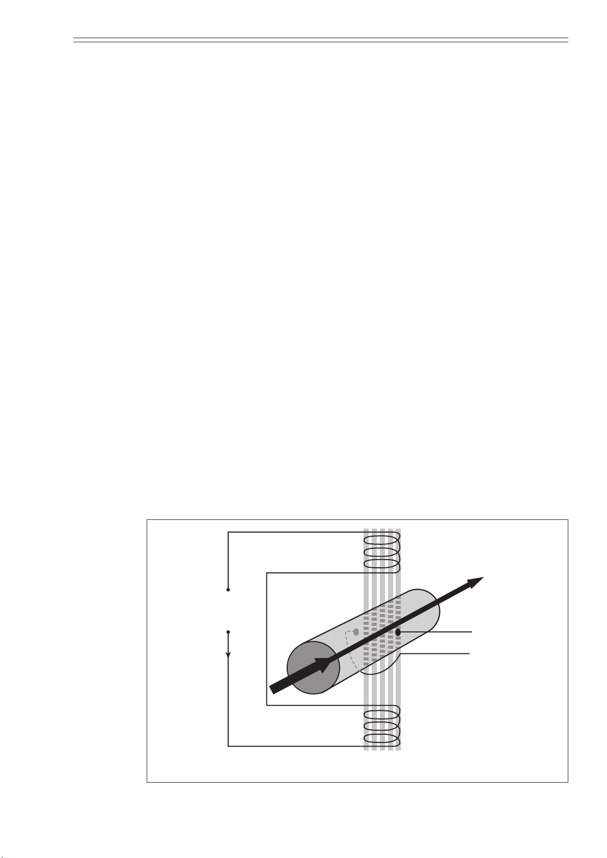
The owmeter works based on the principle of Faraday’s law of electromagnetic
induction, which states that if an electrical conductor, in this case the measured
conductive liquid, passes through a magnetic eld a small electromotive force (EMF)
is induced perpendicular to the eld and ow (refer to Figure 1-1).
Faraday’s law:
E = k BDV when
E = Induced voltage (EMF)
B = Strength of the magnetic eld
D = Conductor width (electrode spacing)
V = Velocity of the conductor
k = Correction factor
This induced EMF is proportional to the average ow rate and is detected by
two electrodes (E
converter.
The only variable in this application of Faraday’s law is the ow rate (V) of the
conductive measured liquid, because eld strength (B), is controlled constant and
electrode spacing (D) is xed.
Therefore, the output electromotive force is directly proportional to liquid ow rate,
resulting in the linear output of a magnetic owmeter.
and E2) mounted in the wall of the detector and then fed to the
1
Magnetic
field (B)
Flow rate (V)
voltage
supply
Measuring fluid
E1
E2
Figure 1-1 Faraday’s law
MagneW FLEX+/PLUS+ Electromagnetic Flowmeter Detector 1-1
Page 16
Introduction Azbil Corporation
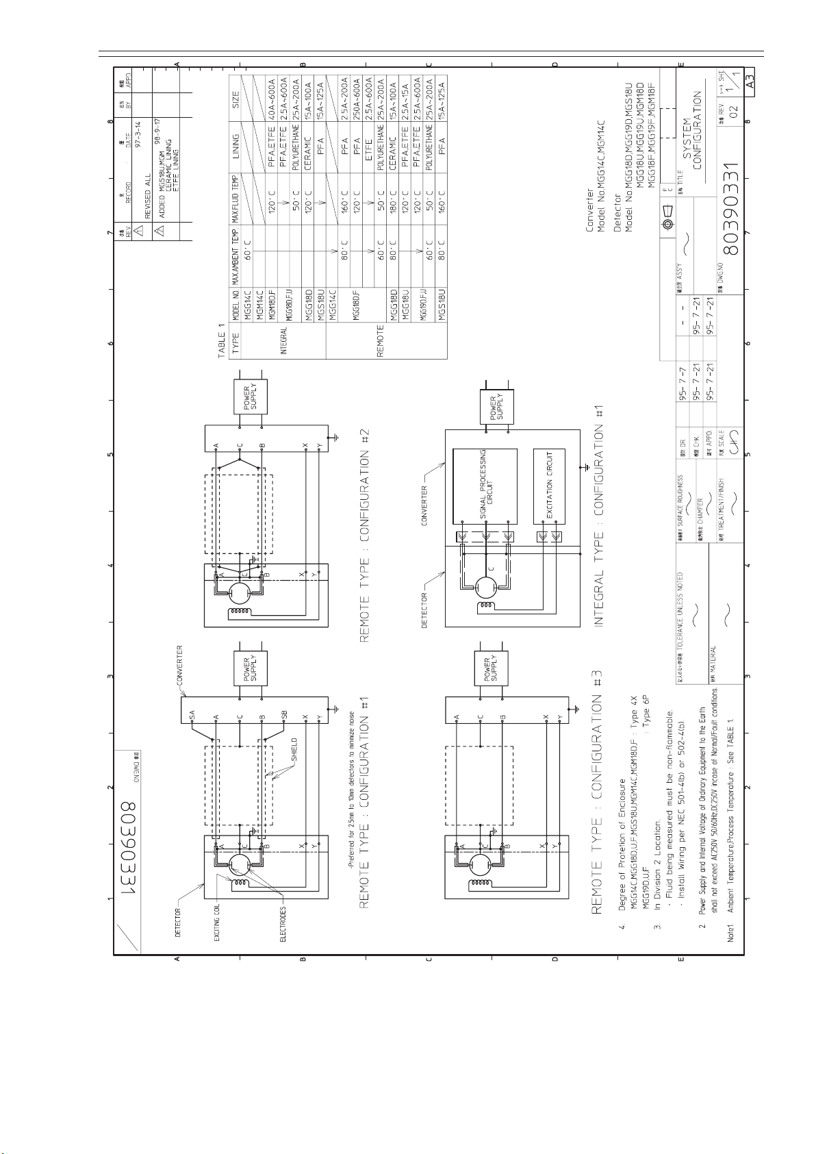
1.2 : System operation
Introduction
Depending on how it is combined with the converter, this product is available in two
congurations, integral and remote.
• Integral: Detector and converter are installed as an integrated unit on a pipe.
• Remote: Detector and converter are installed connected by cable.
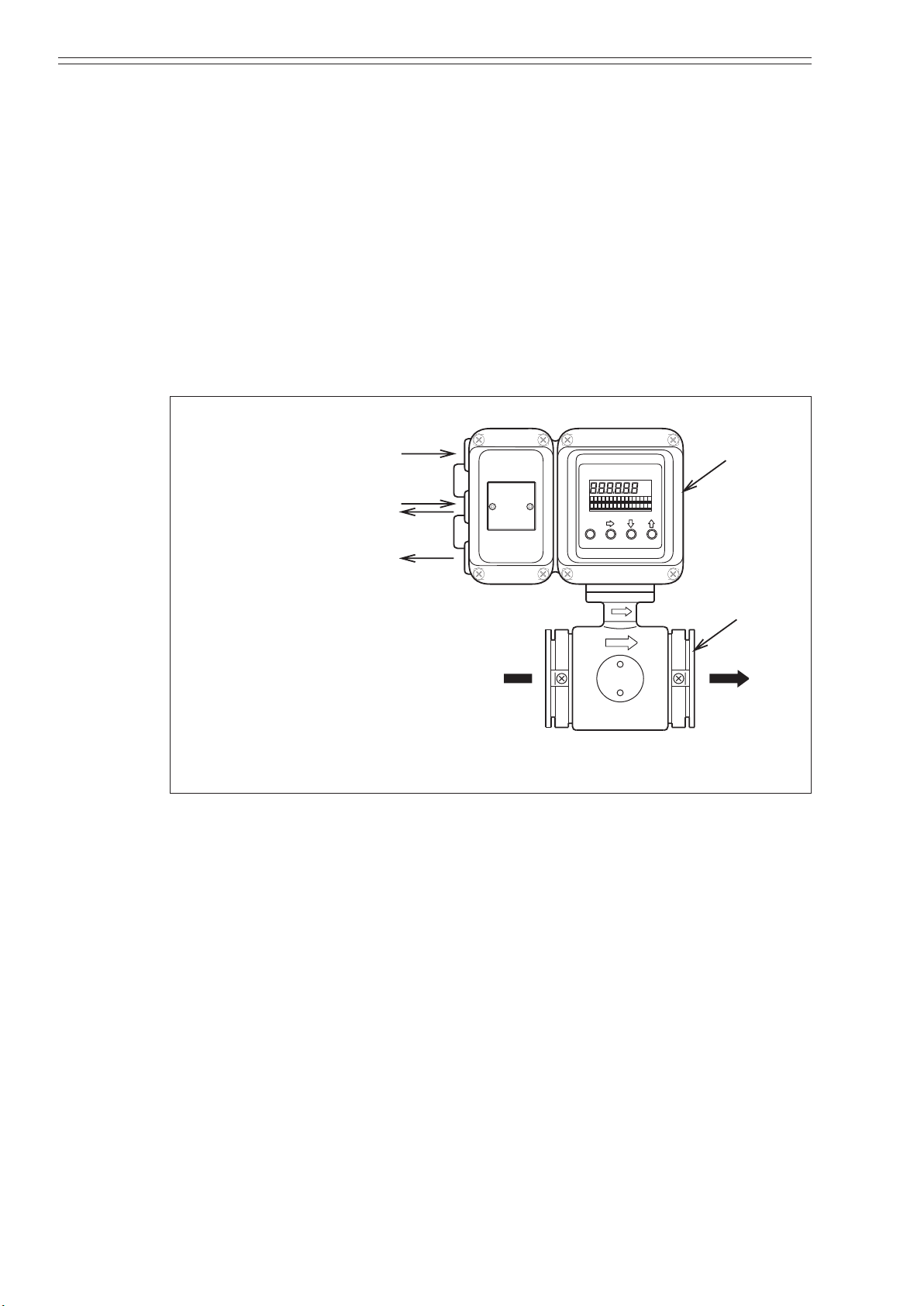
1.2.1: Integral type
Figure 1-2 and Figure 1-3 show examples of measurement systems using the device.
/
Figure 1-2 Integral conguration
1-2 MagneW FLEX+/PLUS+ Electromagnetic Flowmeter Detector
Page 17
Azbil Corporation Introduction
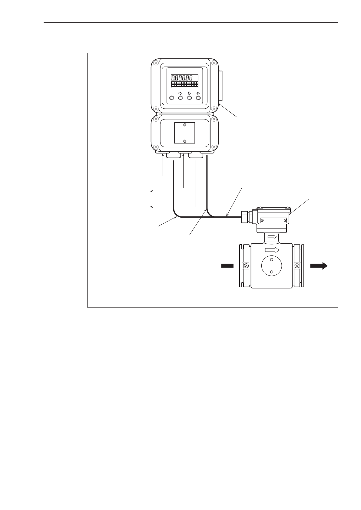
Contact input/output
1.2.2: Remote type
Converter
AC power supply
Pulse output,
Analog output/
Digital output
Dedicated cable
Detector
Excitation output
Flow signal input
Direction of fluid
Figure 1-3 Remote Conguration
MagneW FLEX+/PLUS+ Electromagnetic Flowmeter Detector 1-3
Page 18

Introduction Azbil Corporation
1.3 : Main components
Detector
There are three types of model MGG/MGS Electromagnetic Flowmeter Detectors:
Wafer detectors, Flange detector, and Union / Hose / Clamp detector. The type of
detector you choose depends on your specic installation requirements. All types of
detectors function such that when a conductive uid passes through the detectors, an
electromotive force signal proportional to the ow rate is generated.
WARNING
To prevent the gas or liquid in the pipe from escaping, do not remove the
electrode cover or the electrodes when the detector is installed on a pipe.
1-4 MagneW FLEX+/PLUS+ Electromagnetic Flowmeter Detector
Page 19

Azbil Corporation Introduction
Grounding terminal
Waterproof gland
Grounding ring
Mounting screw (4 places)
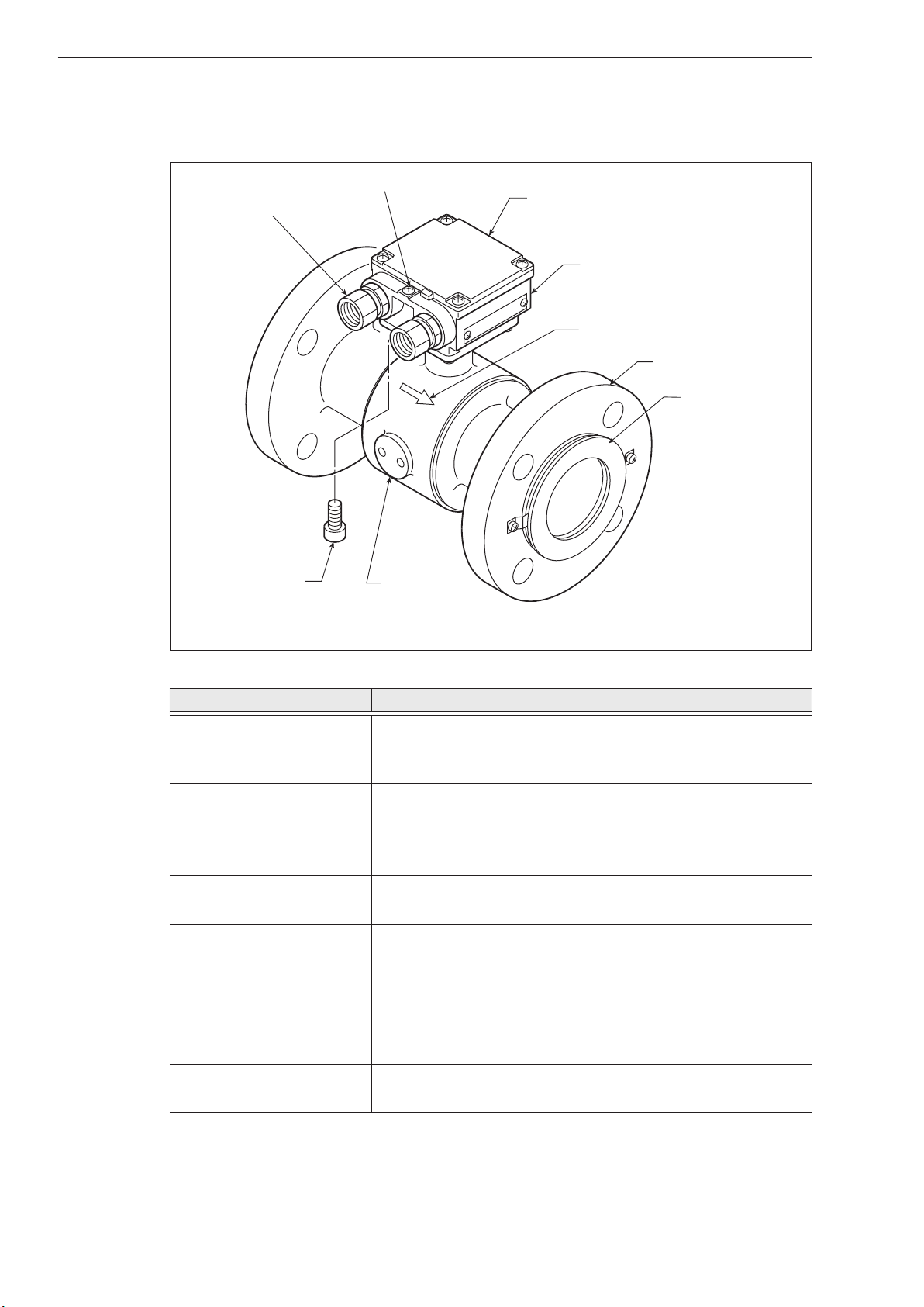
1.3.1: Wafer type detector
A wafer detector consists of the components shown in the gure below.
Terminal box cover
Terminal box
Flow direction mark
Electrode cover
Figure 1-4 Wafer detector main parts
Name Function
Flow direction mark Indicates the direction of uid ow.
Mount the detector so that the measured uid ows in the
direction indicated by this mark.
Electrodes Detect an electromagnetic force signal proportional to the
ow rate of the uid passing through the detector.
The electrode material varies depending on the corrosion
characteristics of the uid to be measured.
Electrode cover Houses the electrodes. Do not remove the cover with the
detector installed on a pipe.
Grounding rings Keep reference voltage as zero by grounding the unit.
The grounding ring material varies depending on the
corrosion characteristics of the uid to be measured.
Terminal box
(Remote model only)
Houses the connection terminals used for applying
a standard voltage. Houses the excitation and signal
terminals.
Terminal box cover
(Remote model only)
MagneW FLEX+/PLUS+ Electromagnetic Flowmeter Detector 1-5
Keeps the terminals dry and protected. Keep the terminal
box cover on during operation.
Page 20
Introduction Azbil Corporation
Mounting screw
(4 places)
Grounding terminal
Grounding ring
1.3.2: Flange type detector
A Flange detector consists of the components shown in the gure below.
Waterproof gland
Terminal box cover
Terminal box
Flow direction mark
Flange
Electrode cover
Figure 1-5 Flange detector main parts
Flow direction mark Indicates the direction of uid ow. Mount the detector
Electrodes Detect an electromagnetic force signal proportional to
Electrode cover Houses the electrodes. Do not remove the cover with the
Grounding rings Keep reference voltage as zero by grounding the unit.
Terminal box
(Remote model only)
Terminal box cover
(Remote model only)
Name Function
so that the measured uid ows in the direction indicated
by this mark.
the ow rate of the uid passing through the detector.
The electrode material varies depending on the corrosion
characteristics of the uid to be measured.
detector installed on a pipe.
The grounding ring material varies depending on the
corrosion characteristics of the uid to be measured.
Houses the connection terminals used for applying
a standard voltage. Houses the excitation and signal
terminals.
Keeps the terminals dry and protected. Keeps the
terminal box cover on during operation.
1-6 MagneW FLEX+/PLUS+ Electromagnetic Flowmeter Detector
Page 21
Azbil Corporation Introduction
Grounding terminal
Terminal box cover
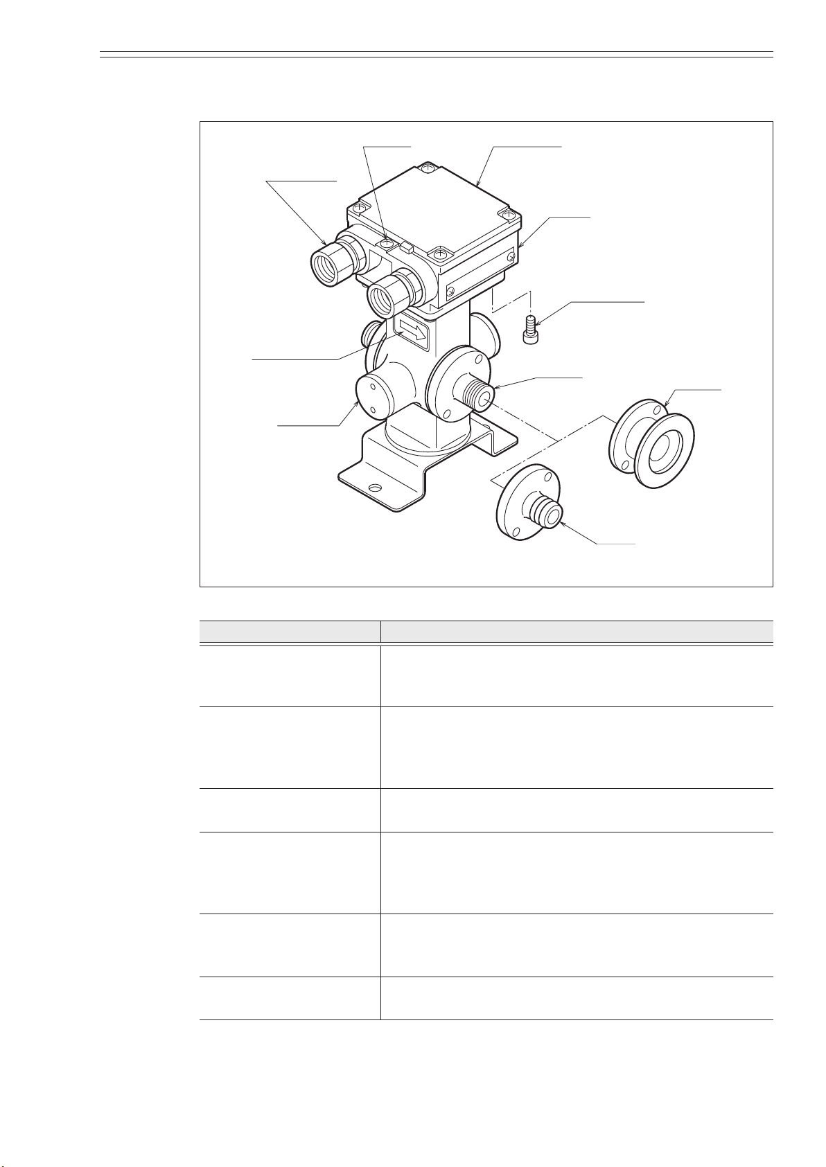
1.3.3: Union / Hose / Clamp type detector
Waterproof
gland
Terminal box
Mounting screw(4 places)
Flow direction
mark
Union
Electrode
cover
Clamp
Hose
Figure 1-6 Union / Hose / Clamp detector main parts
Name Function
Flow direction mark Indicates the direction of uid ow.
Mount the detector so that the measured uid ows in the
direction indicated by this mark.
Electrodes The electrodes generate an electromotive force signal
proportional to the ow rate of the uid passing through
the detector. The electrode material varies depending on
the corrosion characteristics of the uid to be measured.
Electrode cover Houses the electrodes. Do not remove the cover with the
detector installed on a pipe.
Union (Connected by
screws)
Hose
The connection uses a union, hose, and clamp. The
material is SUS316.
Applicable for detector bore diameters of 2.5 to 15 mm.
Clamp
Terminal box
(Remote model only)
Houses the connection terminals used to apply a standard
voltage.
Houses excitation and signal terminals.
Terminal box cover
Keeps the terminals box cover on during operation.
(Remote model only)
MagneW FLEX+/PLUS+ Electromagnetic Flowmeter Detector 1-7
Page 22
Introduction Azbil Corporation
Terminal box
Grounding
Mounting screw
Flow direction mark
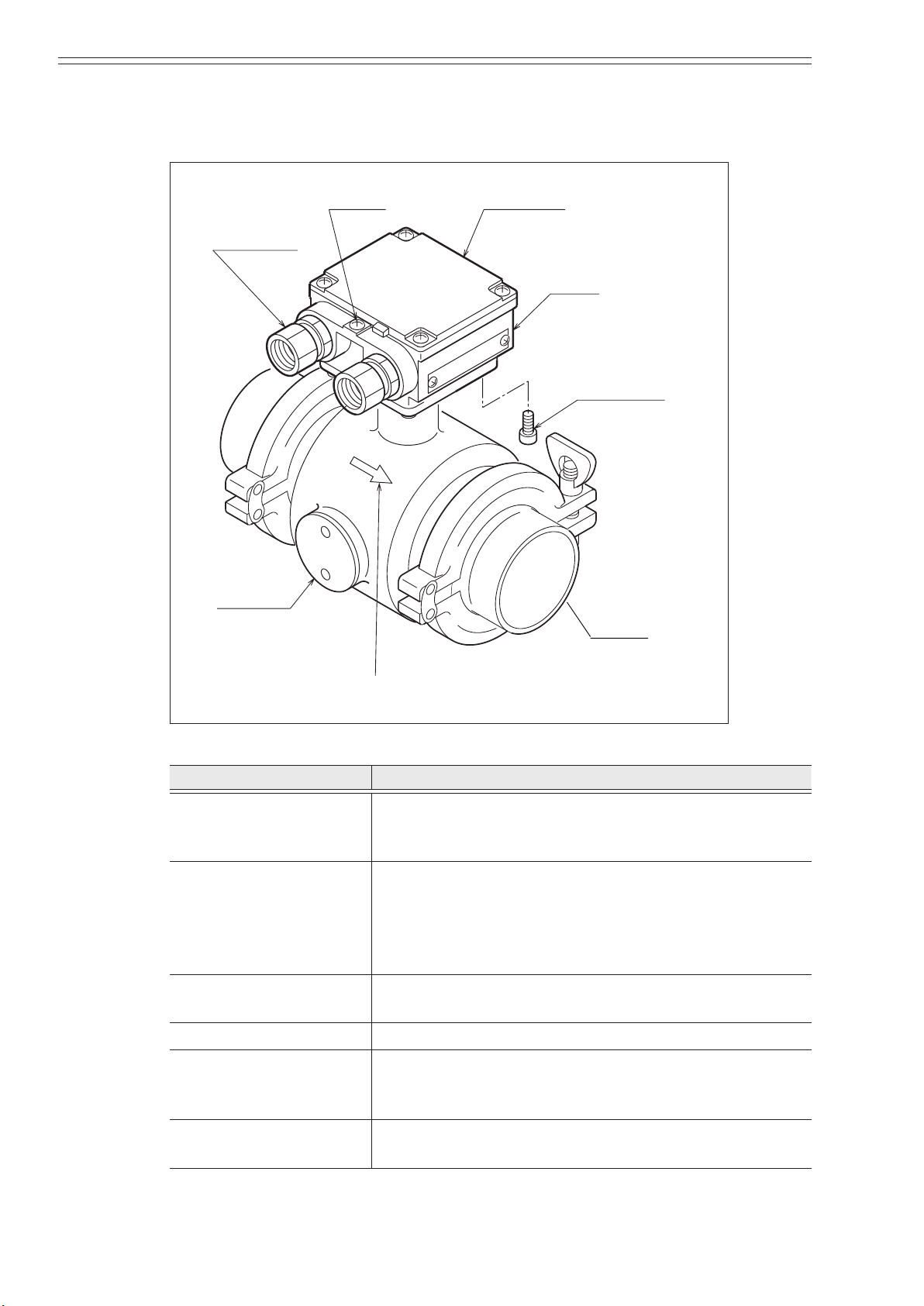
1.3.4: Sanitary type detector
Figure 1-7 shows the structure of the detector and the names of its major parts.
Waterproof
gland
Electrode
cover
terminal
cover
Terminal
box
(4 places)
Ferrule
Figure 1-7 Details of the clamp type detector
Name Function
Flow direction mark Indicates the direction of uid ow.
Mount the detector so that the measured uid ows in the
direction indicated by this mark.
Electrodes The electrodes generate an electromotive force signal
proportional to the ow rate of the uid passing through
the detector.
The electrode material varies depending on the corrosion
characteristics of the uid to be measured.
Electrode cover Houses the electrodes. Do not remove the cover with the
detector installed on a pipe.
Clamp Clamp structure varies IDF clamp and tri-clamp.
Terminal box
(Remote model only)
Houses the connection terminals used to apply a standard
voltage.
Houses excitation and signal terminals.
Terminal box cover
Keeps the terminals box cover on during operation.
(Remote model only)
1-8 MagneW FLEX+/PLUS+ Electromagnetic Flowmeter Detector
Page 23
Azbil Corporation Introduction
Grounding terminal
Excitation terminals
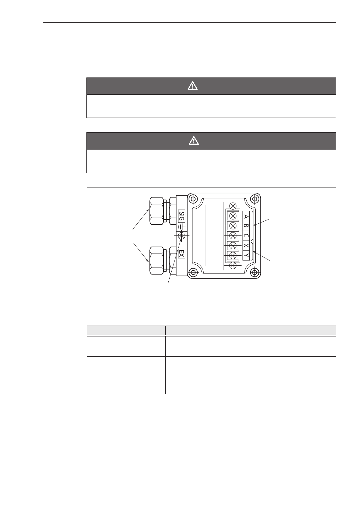
1.3.5: Detector terminal box
The detector terminal box houses the connection terminals used for applying a
standard voltage. Houses the excitation and signal terminals.
WARNING
ELECTRIC SHOCK HAZARD! Turn o power to the converter side before
wiring.
CAUTION
The detector must be grounded (grounding resistance is <100 W) to avoid output
uctuation, zero point instability or output drift.
Signal terminals
Conduit wiring
connectors
Figure 1-8 Detector terminal box main parts
Name Function
Signal terminals Marked A, B and C.
Excitation terminals Marked X and Y.
Conduit wiring
connectors
The excitation cable and the signal cable are wired
through these connectors.
Grounding terminal This terminal is used to ground the detector (grounding
resistance is <100 W).
MagneW FLEX+/PLUS+ Electromagnetic Flowmeter Detector 1-9
Page 24
Introduction Azbil Corporation
1.3.6: Approval of this device
Overview
If 1/2 NPT wiring connection is selected, this device functions as an FM/CSA, nonincendive -approved model. In this case, the installation standards described in this
section must be followed.
Installation of this device
FM/CSA Nonincendive model
THIS EQUIPMENT IS SUITABLE FOR USE IN CLASS I, DIVISION 2, GROUPS
(A, B, C, D), CLASS II/III, DIVISION 2, GROUPS (F, G), OR NON-HAZARDOUS
LOCATIONS ONLY.
CAUTION
(1) Power supply and internal voltage of ordinary equipment to the earth shall not
exceed 250 V AC 50/60 Hz, 250 V DC in case on normal / formal conditions.
(2) Ambient temperature is from -25 to 60°C
(3) Process temperature is from -40 to 160°C (Remote model).
Process temperature is from -40 to 120°C (Integral model)
1-10 MagneW FLEX+/PLUS+ Electromagnetic Flowmeter Detector
Page 25
Azbil Corporation Introduction
If an MGG18/19 detector is used with an MGG14C converter as an FM-approved
nonincendive product, both the detector and the converter should be FM-approved
nonincendive products.
If they are not, the MGG18/19 detector cannot be used as an FM-approved
nonincendive product.
MagneW FLEX+/PLUS+ Electromagnetic Flowmeter Detector 1-11
Page 26

Introduction Azbil Corporation
1-12 MagneW FLEX+/PLUS+ Electromagnetic Flowmeter Detector
Page 27

Chapter 2 : Installation
This section describes unpacking, installation and wiring of the MagneW FLEX+/
.
PLUS+
Depending on the grounding ring or piping material, the required parts or the method
of device installation vary.
2.1 : Unpacking
This device is a precision instrument and should be handled with care to prevent
damage or breakage.
WARNING
This detector is heavy. Dropping it could cause personal injury or damage to the
device.
After unpacking the unit, verify that the following items are present:
• MagneW
• Standard accessories
• Precautions for installation sheet
FLEX+/PLUS+ Detector
2.1.1: Verifying specications
The specications for this device are written on its attached identication plate.
Compare these specications with those listed in Appendix A, device standard
specications and model numbers, and verify that all specications on the plate are
correct, paying special attention to the following:
• Detector size
• Electrode material
• Lining material
• Flange rating
• Grounding ring material
If you have questions regarding the specications of your device, contact your nearest
Azbil Corporation oce or the azbil Group representative. When making an inquiry,
be sure to provide the model number and product number of this device.
MagneW FLEX+/PLUS+ Electromagnetic Flowmeter Detector 2-1
Page 28

Installation Azbil Corporation
2.2 : Storage
WARNING
Before removing the unit, make sure that there is no residual liquid or pressure
inside the piping and the detector to avoid personal injury or damage to the unit.
When storing this device:
• Store the device indoors at room temperature and humidity, in a place safe from
vibration or shock.
• Store the device in the same condition as it was shipped.
When storing this device after use:
(1) Rinse the inside of the detector with water to remove residual uids and then
allow it to dry.
(2) Firmly attach the terminal box cover and the electrode cover in order to keep out
moisture.
(3) Replace the detector in its original packaging.
(4) Store the device indoors at room temperature and humidity, in a place safe from
vibration or shock.
2-2 MagneW FLEX+/PLUS+ Electromagnetic Flowmeter Detector
Page 29

Azbil Corporation Installation
2.3 : Site selection
In order to make full use of the functions of the device, select an optimal installation
site by following the selection criteria below.
CAUTION
Install the unit in a location with an ambient temperature of -30 to +80°C (-22 to +
176°F) and a relative humidity of 5% to 100%. Failing to meet these requirements
could cause damage to the device or cause output errors.
Install the unit away from high-current power lines, motors and transformers to
prevent damage from electromagnetic induction. Failing to meet this requirement
could cause output errors.
Do not install the unit in a location subject to severe vibration or a highly
corrosive atmosphere. Failing to meet this requirement could break the neck of the
detector or cause other damage.
Install the unit as far from direct sunlight as possible to avoid output errors.
CAUTION
The installation location must satisfy the following conditions to avoid output
errors and uctuations.
At the installation location:
• The electrical conductivity of the uid to be measured must match the stated
specication (specs vary according to the converter used) and be more or less
constant.
• The uid to be measured must be electrochemically homogenized. For example,
if two uids are mixed at an upstream point, the device should be installed at
a point so that the two uids can be evenly mixed by the time they reach the
measuring point.
• The distribution of additive matter, if any, must be nearly uniform.
CAUTION
To avoid measurement problems, do not use the MagneW
the following uids, even if their electrical conductivity, temperature and pressure
fall within the specications.
Fluids that have sucient electrical conductivity at high temperatures but do not
satisfy the conductance requirements at room temperature (about 20°C (68°F)).
For example, fatty acids or soap.
• Certain uids that contain surfectants. For example, rinses, shampoos, CWM.
• Conductive adherents. For example, deposition of rosin or conductive material.
• Insulating adherents. For example, oil, kaolinite, kaolin, or calcium stearate.
FLEX+/PLUS+ to measure
CAUTION
This model MGG/MGS detector can only be connected to Azbil Corporation's
model MGG10C/14C converter.
No other types of converter can be used with the device.
MagneW FLEX+/PLUS+ Electromagnetic Flowmeter Detector 2-3
Page 30

Installation Azbil Corporation
Pump
May not ll
Good
2.3.1: Detector position
• Position the detector so that its inner detector passage is continuously lled with
the uid being measured. The following gure provides examples.
Air is easily trapped may not ll with uid
Bad
with uid
Good
Figure 2-1 Detector placement
CAUTION
The detector must be positioned as shown by the circled areas in the gure shown
above. If the pipe is not lled, output errors will occur.
• When measuring high viscosity uid, connecting the pipe to a vertical detector is
recommended (in order to secure an axial symmetrical ow).
• Install a straight pipe section on the upstream side of the detector. The following
gure shows the length of the straight pipe section (D = nominal bore diameter of
the detector).
Upstream
Right angle joint
Detector
> 5D
T-joint
Detector
> 5D
Gate valve (Completely open)
Detector Detector
> 5D
Diffuser with cone angle >15
(<15 Considered straight pipe section)
Detector
> 5D
Concentrator
(Considered straight pipe section)
Detector
> 5D
Any type of valve
> 10D
Figure 2-2 Straight pipe section on upstream side of detector
• Although a pipe section is not necessary on the downstream side, secure a section
of at least 2D if eccentric ow appears.
• Select an installation site where there is no major pulsation or vibration (away
from a pump).
• Make sure that there is adequate space around the detector after installation to
perform maintenance.
2-4 MagneW FLEX+/PLUS+ Electromagnetic Flowmeter Detector
Page 31

Azbil Corporation Installation
(15.75 inches)
400 mm
(15.75 inches)
400 mm
Figure 2-3 Space allowance required for maintenance
2.3.2: Changing the position of the terminal box
In some locations, the direction of the terminal box may be unsuitable if the detector
is installed as it is shipped. In this case, the terminal box can be repositioned before
installation.
After selecting an installation site, adjust the direction of the terminal box using the
method described below.
To change the position of the terminal box:
(1) Using an M5 wrench, remove the four screws securing the terminal box to the
detector.
(2) Holding the detector, rotate the terminal box horizontally to the required position.
CAUTION
Do not rotate the terminal box more than 180° (one half rotation). Any further
rotation can disconnect wiring.
After removing the screws, do not pull on the terminal box. The lead wire can be broken.
When you move the terminal box, make sure the O-ring remains in the groove to
insure an air-tight seal when the unit is reassembled.
(3) Using a hex wrench, retighten the four screws.
Bottom view
Hexagonal wrench
Figure 2-4 Repositioning the terminal box
MagneW FLEX+/PLUS+ Electromagnetic Flowmeter Detector 2-5
Page 32

Installation Azbil Corporation
Nuts (optional)
material grounding
a
supplied.)
2.4 : Installing a wafer detector
CAUTION
Before installing the detector, make sure any foreign matter is ushed from
the interior passage of the detector. Residual foreign matter could cause output
uctuations.
Do not touch the electrodes or allow oil or fat to come into contact with them to
avoid output uctuations.
Align the direction mark on the detector in the direction of the liquid ow.
Misalignment can result in a negative output.
The following gure shows the basic installation method for installing a wafer
detector.
Through-bolts (optional)
Pipe
Gasket (Required
when using SUS
rings. Otherwise,
gasket is
Centering nuts (supplied)
Figure 2-5 Installing a wafer detector
2-6 MagneW FLEX+/PLUS+ Electromagnetic Flowmeter Detector
Page 33

Azbil Corporation Installation
2.4.1: Determining the fastening torque
The following table shows the fastening torque for each pipe bore.
CAUTION
The correct fastening torque must be used to prevent leakage. To avoid damage to
the detector, do not exceed the listed fastening torque.
Table 2-1 Fastening torque for wafer detectors
Nominal detector bore diameter
mm (inch)
2.5 - 15 (0.1 - 3/8) 13 - 18 (9.6 -13.3)
25 (1) 20 - 30 (14.8 - 22.1)
40 - 80 (1½ - 3.1) 30 - 50 (22.1 - 36.9)
100 (4) 50-70 (36.9 - 51.6)
125 - 150 (5 - 6) 80 -100 (59.0 - 73.8)
200 (4) 90 -100 (66.4 - 73.8)
2.4.2: Selecting the ange shape
The anges used for installation should maximize the area of contact with the gasket.
O Acceptable X Unacceptable
Flange
Fastening torque
N•m (ft•lb)
Welding
Pipe
Welding
(The liquid could leak because of the
small area of contact with the gasket.)
Figure 2-6 Flange Shapes
CAUTION
Before installing the detector, make sure that the pipe is exactly straight and
centered. Any irregularity could cause leakage or other hazards.
MagneW FLEX+/PLUS+ Electromagnetic Flowmeter Detector 2-7
Page 34

Installation Azbil Corporation
Tilted pipe Off-center Off-center
Figure 2-7 Unacceptable positioning
CAUTION
Never attempt to force the detector between two anges if the space is too narrow.
It can damage the detector.
Figure 2-8 Unacceptable placement of detector between anges
CAUTION
Make certain the bore diameters of the pipe and the detector are exactly the same
and install the detector so that the gasket does not protrude into the inner bore of
the pipe, as this could result in leakage or other hazards.
CAUTION
Tighten each bolt a little at a time and apply uniform pressure to all the bolts.
If leakage continues after tightening the bolts, make sure that the pipe is not o
center, then continue to tighten each bolt a little at a time.
2-8 MagneW FLEX+/PLUS+ Electromagnetic Flowmeter Detector
Page 35

Azbil Corporation Installation
Flange
position
Flange
Position
2.4.3: Necessary parts
You will need the following parts to install a wafer detector:
• Centering nuts (four supplied)
• Connecting bolts and nuts (available separately)
• Gaskets: Required when using grounding rings made of SUS material. Not
required when using grounding rings made of hastelloy, titanium, tantalum, or
platinum.
• Protective Plate: Required when connecting the detector to polyvinyl chloride
(PVC) piping.
Centering nuts
The centering nuts create the exact alignment of the pipe and detector. These nuts
are positioned on through-bolts and the detector is set on top of the nuts to properly
position it against the anges.
The position of the centering nuts depends on the direction in which the detector is
installed. For horizontal centering of the detector, position two centering nuts against
each ange. For vertical centering of the detector, position the four centering nuts on
the bottom ange. The following gures show horizontal and vertical centering nut
positions.
Centering nut
Figure 2-9 Centering nut positioning for horizontal centering
Centering Nut
Figure 2-10 Centering nut positioning for vertical centering
MagneW FLEX+/PLUS+ Electromagnetic Flowmeter Detector 2-9
Page 36

Installation Azbil Corporation
Gaskets
Gaskets are supplied with the grounding ring, except when it is made of SUS
material. If you are using SUS material, you must provide the gaskets. Azbil
Corporation recommends joint sheet or polytetraouroethylene (PTFE) gasket
material. For the inner (bore) diameters of the gaskets, see the following table.
Rubber gaskets are not recommended.
CAUTION
Using a gasket with too small a diameter can aect the ow velocity distribution,
resulting in inaccurate measurement.
Using a gasket with too large a diameter can cause leakage. Also, any solid
substance in the uid to be measured could accumulate between the gasket and the
ange, resulting in inaccurate measurement.
Table 2-2 Recommended inner diameters of gaskets
Nominal
detector
bore
diameter
Gasket
inner
diameter
mm
(inch)
mm
±
(inch)
±
2.5 5 10 15 25 40 50 65 80 100 125 150 200
0.1 0.2 3/8 1/2 1 1½ 2 2½ 3 4 5 6 8
6161111161251401511641761101112411481196
1
0.24
0.24
0.43
0.63
0.98
1.57
2.01
2.52
2.99
3.98
4.88
5.83
7.72
0.04
0.04
0.04
0.04
0.04
0.04
0.04
0.04
0.04
0.04
0.04
0.04
0.04
If you install the detector at a lower torque level using rubber gaskets, you must use
gaskets with the bore and outer diameters for the respective pipe bore shown in the
following table. Depending on the grounding ring material, two gaskets of dierent
thicknesses may be required. The following two tables provide the inner and outer
diameters for the two dierent gasket thicknesses.
2-10 MagneW FLEX+/PLUS+ Electromagnetic Flowmeter Detector
Page 37

Azbil Corporation Installation
Table 2-3 Inner and outer diameters of rubber gaskets of thickness 0.5 to 1 mm
(0.02 to 0.04 inches)
Nominal
detector
bore
diameter
Gasket
inner
diameter
Gasket
outer
diameter
mm
(inch)
mm
±
(inch)
±
mm
±
(inch)
±
2.5 5 10 15 25 40 50 65 80 100 125 150 200
0.1 0.2 3/8 1/2 1 1½ 2 2½ 3 4 5 6 8
6161111161251401511641761101112411481196
1
0.24
0.24
0.43
0.63
0.98
1.57
2.01
2.52
2.99
3.98
4.88
5.83
7.72
0.04
0.04
0.04
0.04
0.04
0.04
0.04
0.04
0.04
0.04
0.04
0.04
0.04
34134134134150175191111111211146117712071257
1
1.34
1.34
1.34
1.34
1.97
2.95
3.58
4.37
4.76
5.75
6.97
8.15
10.12
0.04
0.04
0.04
0.04
0.04
0.04
0.04
0.04
0.04
0.04
0.04
0.04
0.04
Table 2-4 Inner and outer diameters of rubber gaskets of thickness 3 to 4 mm
(0.12 to 0.16 inches)
Nominal
detector
bore
diameter
mm
(inch)
2.5 5 10 15 25 40 50 65 80 100 125 150 200
0.1 0.2 3/8 1/2 1 1½ 2 2½ 3 4 5 6 8
Gasket
inner
diameter
Gasket
outer
diameter
mm
±
(inch)
±
mm
±
(inch)
±
6161111161251391511641761101112411481196
1
0.24
0.24
0.43
0.63
0.98
1.54
2.01
2.52
2.99
3.98
4.88
5.83
7.72
0.04
0.04
0.04
0.04
0.04
0.04
0.04
0.04
0.04
0.04
0.04
0.04
0.04
34134134134150168184110411141139116611901240
1
1.34
1.34
1.34
1.34
1.97
2.68
3.31
4.09
4.49
5.47
6.54
7.48
9.45
0.04
0.04
0.04
0.04
0.04
0.04
0.04
0.04
0.04
0.04
0.04
0.04
0.04
MagneW FLEX+/PLUS+ Electromagnetic Flowmeter Detector 2-11
Page 38

Installation Azbil Corporation
2.4.4: Selecting an installation method
To select an installation method you must determine the following:
• Horizontal or vertical placement of the detector
• Mounting pipe material
• Grounding ring material
• Need for a protective plate
• Use of rubber gaskets
CAUTION
The necessary materials and the installation method vary according to the material
of the ring and that of the pipe on which the detector is to be installed. Select the
appropriate method of installation from the following table after conrming the
specications of the detector to be installed and the conditions of installation.
Improper installation can result in leakage or damage to the pipe anges.
Table 2-5 Wafer detector installation methods
Pipe
material
Grounding ring
material
Installation Requirements See Page
Metal SUS material With specied fastening torque page 2-15
With rubber gaskets and low
page 2-17
fastening torque
Non-SUS material With specied fastening torque page 2-16
With rubber gaskets and low
page 2-17
fastening torque
PVC SUS material With specied fastening torque page 2-19
With a protective plate page 2-20
With rubber gaskets and low
page 2-21
fastening torque
Non-SUS material With specied fastening torque page 2-22
With a protective plate page 2-23
With rubber gaskets and low
page 2-24
fastening torque
2-12 MagneW FLEX+/PLUS+ Electromagnetic Flowmeter Detector
Page 39

Azbil Corporation Installation
Flange
f
fluid flow
2.4.5: Installation on a horizontal pipe
To install a wafer detector on a horizontal pipe:
Follow this procedure to install the detector on a horizontal pipe.
Step Action Drawing
1 • Insert through-bolts in the ange holes
shown by black dots in the drawing. Slip
two centering nuts onto each through-bolt
before inserting the bolts.
2 • Turn the detector so that the direction mark
on the detector matches the direction of
uid ow.
• Insert the detector and gaskets between the
pipe anges.
• Position the detector so that it sits on top of
the centering.
3 • Make sure that the detector remains
properly centered.
• Make sure that the gaskets do not protrude
beyond the edges of the pipe anges.
• When you have checked these items, insert
the remaining through-bolts into the ange
holes and tighten the bolts evenly using the
appropriate fastening torque given on page
2-7.
Gasket
Direction o
MagneW FLEX+/PLUS+ Electromagnetic Flowmeter Detector 2-13
Page 40

Installation Azbil Corporation
Flange
Centering nuts
Direction of
Direction of
2.4.6: Installation on a vertical pipe
Follow this procedure to install the detector on a horizontal pipe.
Step Action Drawing
1 • Of the ange holes shown by black dots in the
drawing, insert through-bolts into the two holes
at the back and fasten them lightly with nuts.
Slip one centering nut onto each through bolt
before inserting the bolts.
2 • Turn the detector so that the direction mark on
the detector matches the direction of uid ow.
• Insert the detector and gaskets between the pipe
anges.
fluid flow
Terminal
box side
Back
Gaskets
3 • Insert through-bolts tted with one centering
nut each into the remaining two ange holes
shown by black dots in steps 1 and 2.
4 • Make sure that the detector remains properly
centered.
• Make sure that the gaskets do not protrude
beyond the edges of the pipe anges.
• When you have checked these items, insert
the remaining through-bolts into the ange
holes and tighten the bolts evenly using the
appropriate fastening torque given on page
2-7.
fluid flow
Gaskets
2-14 MagneW FLEX+/PLUS+ Electromagnetic Flowmeter Detector
Page 41

Azbil Corporation Installation
Grounding ring
2.4.7: Installation on a metal pipe using SUS grounding ring material
The installation method described in this section is for installation on a metal pipe
using SUS grounding ring material. For the installation method corresponding to any
other combination of materials, refer to Table 2-5 on page 2-12.
For installation using SUS grounding ring material, Azbil Corporation recommends
non-rubber gaskets such as joint sheet or PTFE. Although rubber gaskets can be used,
it is not possible to reduce the fastening torque. See page 2-17 for installation using
rubber gaskets.
CAUTION
The use of rubber gaskets is not recommended and can cause leakage.
To install a wafer detector on a metal pipe using SUS grounding ring material
and a specied torque:
• Install the detector as shown in the following illustration. The torque level for
tightening the bolts is not related to the gasket material.
See Table 2-1 on page 2-7 for the appropriate torque.
See Table 2-2 on page 2-10 for the inner diameter of the gasket.
Pipe side
flange
Lining
Gasket
Figure 2-11 Installation on a metal pipe using SUS grounding ring material and a
specied torque
MagneW FLEX+/PLUS+ Electromagnetic Flowmeter Detector 2-15
Page 42

Installation Azbil Corporation
Grounding ring
2.4.8: Installation on a metal pipe using non-SUS grounding ring material
The installation methods described in this section are for installation on a metal pipe
using non-SUS grounding ring material. For the installation method corresponding to
any other combination of materials, refer to Table 2-5 on page 2-12.
PTFE gaskets are provided for this type of installation. Although rubber gaskets
can be used, it is not possible to reduce the fastening torque. See page 2-17 for
installation using rubber gaskets.
CAUTION
The use of anything other than the PTFE gaskets provided can result in leakage.
The use of rubber gaskets is not recommended and can cause leakage.
To install a wafer detector on a metal pipe using non-SUS grounding ring
material and a specied torque:
• Install the detector as shown in the following illustration. The torque level for
tightening the bolts is not related to the gasket material.
See Table 2-1 on page 2-7 for the appropriate torque.
See Table 2-2 on page 2-10 for the inner diameter of the gasket.
Lining
Figure 2-12 Installation on a metal pipe using non-SUS grounding ring material
and a specied torque
2-16 MagneW FLEX+/PLUS+ Electromagnetic Flowmeter Detector
PTFE gasket
Page 43

Azbil Corporation Installation
(0.02 to 0.04 inch)
To install a wafer detector on a metal pipe using non-SUS grounding ring
material with rubber gaskets:
CAUTION
The use of anything other than the PTFE gaskets provided can result in leakage.
The use of rubber gaskets is not recommended and can cause leakage.
(1) Remove the grounding ring from the detector and insert a rubber gasket 0.5 to 1.0
mm (0.02 to 0.04 inch) thick between the lining and the grounding ring.
(2) Reinsert the grounding ring on top of the rubber gasket.
(3) Remove the PTFE gasket and insert a rubber gasket 3.0 to 4.0 mm (0.12 to 0.16
inch) to replace it.
(4) With the rubber gaskets in the position shown in the following gure, attach the
detector to the pipe. Both rubber gaskets should be made of the same material.
See Table 2-3 on page 2-11 and Table 2-4 on page 2-11 for the rubber gasket
dimensions.
Rubber gasket
Lining
Grounding ringRubber gasket
0.5 to 1 mm
3 to 4 mm
(0.12 to 0.16 inch)
Figure 2-13 Installation on a metal pipe using non-SUS grounding ring material
with rubber gaskets
(5) Fasten the bolts with a torque that provides a leakproof joint.
MagneW FLEX+/PLUS+ Electromagnetic Flowmeter Detector 2-17
Page 44

Installation Azbil Corporation
Grounding ring
Gasket
Lining
PTFE gasket
Figure 2-14 Incorrect installation
2-18 MagneW FLEX+/PLUS+ Electromagnetic Flowmeter Detector
Page 45

Azbil Corporation Installation
Grounding ring
2.4.9: Installation on a PVC pipe using SUS grounding ring material
The installation methods described in this section are for installation on a PVC pipe
using SUS grounding ring material. For the installation method corresponding to any
other combination of materials, refer to Table 2-5 on page 2-12.
PTFE gaskets are provided for this type of installation. If you supply the gaskets,
Azbil Corporation recommends non-rubber gaskets such as joint sheet or PTFE.
Although rubber gaskets can be used, they are not recommended. See page 2-21 for
installation using rubber gaskets.
CAUTION
The use of rubber gaskets and a lower fastening torque is not recommended and
can cause insucient surface pressure between the lining and the grounding ring,
resulting in leakage.
If tightening the bolts at the specied torque threatens to warp or damage the PVC
pipes, you will need to use a protective plate. See page 2-20 for installation of the
protective plate.
To install a wafer detector on a PVC pipe using SUS grounding ring material
with a specied fastening torque:
• Install the detector as shown in the following illustration. The torque level for
tightening the bolts is not related to the gasket material.
See Table 2-1 on page 2-7 for the appropriate torque.
See Table 2-2 on page 2-10 for the inner diameter of the gasket.
Lining
Figure 2-15 Installation on a PVC pipe using SUS grounding ring material
MagneW FLEX+/PLUS+ Electromagnetic Flowmeter Detector 2-19
Gasket
Page 46

Installation Azbil Corporation
Grounding ring
Protective plate
To install a wafer detector on a PVC pipe using SUS grounding ring material
and a protective plate:
Use this method to install the detector using a protective plate to prevent the PVC
pipe from being deformed or damaged when the bolts are tightened with the specied
torque.
• Install the protective plate between the outer side of the PVC ange and the
detector, as shown in the gure below. The protective plate protects the PVC
pipe. The torque level for tightening the bolts is not related to the gasket material.
See Table 2-1 on page 2-7 for the appropriate torque.
See Table 2-2 on page 2-10 for the inner diameter of the gasket.
Lining
Gasket
Figure 2-16 Installation on a PVC pipe using SUS grounding ring material and a
protective plate
2-20 MagneW FLEX+/PLUS+ Electromagnetic Flowmeter Detector
Page 47

Azbil Corporation Installation
(0.02 to 0.04 inch)
To install a wafer detector on a PVC pipe using SUS grounding ring material
with rubber gaskets and a low fastening torque:
CAUTION
The use of rubber gaskets and a lower fastening torque is not recommended and
can cause insucient surface pressure between the lining and the grounding ring,
resulting in leakage.
(1) Remove the grounding ring from the detector and insert a rubber gasket 0.5 to 1.0
mm (0.02 to 0.04 inch) thick between the lining and the grounding ring.
(2) Reinsert the grounding ring on top of the rubber gasket.
(3) With the rubber gasket in the position shown in the following gure, attach the
detector to the pipe. In the example shown, both rubber gaskets are made of the
same material.
Rubber gasket
Lining
Grounding ringRubber gasket
0.5 to 1 mm
3 to 4 mm
(0.12 to 0.16 inch)
Figure 2-17 Installation on a PVC pipe using SUS grounding ring material with
rubber gaskets (Not recommended)
(4) Fasten the bolts with a torque that provides a leakproof joint.
MagneW FLEX+/PLUS+ Electromagnetic Flowmeter Detector 2-21
Page 48

Installation Azbil Corporation
Grounding ring
2.4.10: Installation on a PVC pipe using non-SUS grounding ring material
The installation methods described in this section are for installation on a PVC pipe
using non-SUS grounding ring material. For the installation method corresponding to
any other combination of materials, refer to Table 2-5 on page 2-12.
PTFE gaskets are provided for this type of installation. If you supply the gaskets,
Azbil Corporation recommends non-rubber gaskets such as joint sheet or PTFE.
Although rubber gaskets can be used, they are not recommended. See page 2-24 for
installation using rubber gaskets.
CAUTION
The use of rubber gaskets and a lower fastening torque is not recommended and
can cause insucient surface pressure between the lining and the grounding ring,
resulting in leakage.
If tightening the bolts at the specied torque threatens to warp or damage the PVC
pipes, you will need to use a protective plate. See page 2-23 for installation of the
protective plate.
To install a wafer detector on a PVC pipe using non-SUS grounding ring
material with a specied fastening torque:
• Install the detector as shown in the following illustration. The torque level for
tightening the bolts is not related to the gasket material.
See Table 2-1 on page 2-7 for the appropriate torque.
See Table 2-2 on page 2-10 for the inner diameter of the gasket.
Lining
Figure 2-18 Installation on a PVC pipe using non-SUS grounding ring material
2-22 MagneW FLEX+/PLUS+ Electromagnetic Flowmeter Detector
PTFE gasket (supplied)
Page 49

Azbil Corporation Installation
Grounding ring
Protective plate
To install a wafer detector on a PVC pipe using non-SUS grounding ring
material and a protective plate:
Use this method to install the detector using a protective plate to prevent the PVC
pipe from being deformed or damaged when the bolts are tightened with the specied
torque.
• Install the protective plate between the outer side of the PVC ange and the
detector, as shown in the gure below. The protective plate protects the PVC
pipe. The torque level for tightening the bolts is not related to the gasket material.
See Table 2-1 on page 2-7 for the appropriate torque.
See Table 2-2 on page 2-10 for the inner diameter of the gasket.
Lining
PTFE gasket
(Supplied)
Figure 2-19 Installation on a PVC pipe using non-SUS grounding ring material
and a protective plate
MagneW FLEX+/PLUS+ Electromagnetic Flowmeter Detector 2-23
Page 50

Installation Azbil Corporation
(0.02 to 0.04 inch)
To install a wafer detector on a PVC pipe using non-SUS grounding ring
material with rubber gaskets and a low fastening torque:
CAUTION
The use of rubber gaskets and a lower fastening torque is not recommended and
can cause insucient surface pressure between the lining and the grounding ring,
resulting in leakage.
(1) Remove the grounding ring from the detector and insert a rubber gasket 0.5 to 1.0
mm (0.02 to 0.04 inch) thick between the lining and the grounding ring.
(2) Reinsert the grounding ring on top of the rubber gasket.
(3) Remove the PTFE gasket and insert a rubber gasket 3.0 to 4.0 mm (0.12 to 0.16
inch) to replace it.
(4) With the rubber gaskets in the position shown in the following gure, attach the
detector to the pipe. Both rubber gaskets should be made of the same material.
See Table 2-3 on page 2-11 and Table 2-4 on page 2-11 for the appropriate
dimensions.
Rubber gasket
Lining
Grounding ringRubber gasket
0.5 to 1 mm
3 to 4 mm
(0.12 to 0.16 inch)
Figure 2-20 Installation on a PVC pipe using non-SUS grounding ring material
with rubber gaskets
(5) Fasten the bolts with a torque that provides a leakproof joint.
2-24 MagneW FLEX+/PLUS+ Electromagnetic Flowmeter Detector
Page 51

Azbil Corporation Installation
Nuts (optional)
2.5 : Installing a anged detector
CAUTION
Before installing the detector, make sure any foreign matter is ushed from
the interior passage of the detector. Residual foreign matter could cause output
uctuations.
Do not touch the electrodes or allow oil or fat to come into contact with them to
avoid output uctuations.
Align the direction mark on the detector in the direction of the liquid ow.
Misalignment can result in a negative output.
The following gure shows the basic installation method for installing a anged
detector.
Through-bolts (optional)
Pipe
Gasket (Required when
using SUS material
grounding rings.
Otherwise, a gasket is
supplied.)
Figure 2-21 Installing a anged detector
MagneW FLEX+/PLUS+ Electromagnetic Flowmeter Detector 2-25
Page 52

Installation Azbil Corporation
2.5.1: Determining the fastening torque
The following table shows the fastening torque for each pipe bore.
CAUTION
The correct fastening torque must be used to prevent leakage. To avoid damage to
the detector, do not exceed the listed fastening torque.
Table 2-6 Fastening torque for anged detectors
Nominal
detector bore
diameter
mm (inch)
2.5 - 15 mm
(0.1 - 3/8 inch)
25 mm
(1 inch)
Flange ratings
JIS 10K
JIS 20K
JIS 30K
JPI 150
JPI 300
ANSI 150
ANSI 300
DIN PN10/16
DIN PN25/40
JIS 10K
JIS 20K
JIS 30K
JPI 150
JPI 300
ANSI 150
ANSI 300
6 - 9
6 - 9
18 - 31
6 - 9
6 - 9
6 - 9
9 - 14
21 - 31
21 - 32
23 - 36
11 - 17
22 - 34
Fastening torque
N•m (ft•lb)
(4.4 - 6.6)
(4.4 - 6.6)
(13.3 - 22.9)
(4.4 - 6.6)
(4.4 - 6.6)
(4.4 - 6.6)
(6.6 - 10.3)
(15.5 - 22.9)
(15.5 - 23.6)
(17.0 - 26.6)
(8.1 - 12.5)
(16.2 - 25.1)
kgf•cm
61 - 92
61 - 92
184 - 316
61 - 92
61 - 92
61 - 92
92 - 143
214 - 316
214 - 326
235 - 367
112 - 173
224 - 347
40 mm
(1½ inches)
DIN PN10/16
DIN PN25/40
JIS 10K
JIS 20K
JIS 30K
10 - 14
12 - 18
22 - 32
22 - 34
41 - 65
(7.4 - 10.3)
(8.9 - 13.3)
(16.2 - 23.6)
(16.2 - 25.1)
(30.2 - 47.9)
102 - 143
122 - 184
224 - 326
224 - 347
418 - 663
JPI 150
JPI 300
ANSI 150
ANSI 300
DIN PN10/16
DIN PN25/40
2-26 MagneW FLEX+/PLUS+ Electromagnetic Flowmeter Detector
13 - 18
36 - 57
22 - 32
25 - 38
(9.6 - 13.3)
(26.6 - 42.0)
(16.2 - 23.6)
(18.4 -28.0)
133 - 184
367 - 581
224 - 326
255 -387
Page 53

Azbil Corporation Installation
Table 2-6 Fastening torque for anged detectors
Nominal
detector bore
diameter
mm (inch)
50 / 65 mm
(2 / 2½ inches)
80 mm
(3 inches)
Flange ratings
JIS 10K
JIS 20K
JIS 30K
JPI 150
JPI 300
ANSI 150
ANSI 300
DIN PN10/16
DIN PN25/40
JIS 10K
JIS 20K
JIS 30K
JIS G3451 F12
JPI 150
JPI 300
ANSI 150
ANSI 300
24 - 34
19 - 31
22 - 34
23 - 32
20 - 32
24 - 34
28 - 42
20 - 31
37 - 61
42 - 66
18 - 37
26 - 35
37 - 57
Fastening torque
N•m (ft•lb)
(17.7 - 25.1)
(14.0 - 22.9)
(16.2 - 25.1)
(17.0 - 23.6)
(14.8 - 23.6)
(17.7 - 25.1)
(20.7 - 31.0)
(14.8 - 22.9)
(27.3 - 45.0)
(31.0 - 48.7)
(13.3 - 27.3)
(19.2 - 25.8)
(27.3 - 42.0)
kgf•cm
245 - 347
194 - 316
224 - 347
235 - 326
204 - 326
245 - 347
286 - 428
204 - 316
377 - 622
428 - 673
184 - 377
265 - 357
377 - 581
100 mm
(4 inches)
125 / 150 mm
(5 / 6 inches)
DIN PN10/16
DIN PN25/40
JIS 10K
JIS 20K
JIS 30K
JIS G3451 F12
JPI 150
JPI 300
ANSI 150
ANSI 300
DIN PN10/16
DIN PN25/40
JIS 10K
JIS 20K
JIS 30K
JIS G3451 F12
JPI 150
JPI 300
ANSI 150
ANSI 300
20 - 31
25 - 39
22 - 33
41 - 66
61 - 95
21 - 41
21 - 31
43 - 66
22 - 33
48 - 74
47 - 67
58 - 91
80 - 123
23 - 45
42 - 60
50 - 74
(14.8 - 22.9)
(18.4 - 28.8)
(16.2 - 24.3)
(30.2 - 48.7)
(45.0 - 70.1)
(15.5 - 30.2)
(15.5 - 22.9)
(31.0 - 48.7)
(16.2 - 24.3)
(35.4 - 54.6)
(34.7 - 49.4)
(42.8 - 67.1)
(59.0 - 90.7)
(17.0 - 33.2)
(31.0 - 44.3)
(36.9 - 54.6)
204 - 316
255 - 398
224 - 337
418 - 673
622 - 969
214 - 418
214 - 316
438 - 673
224 - 337
489 - 755
479 - 683
591 - 928
816 - 1254
235 - 459
428 - 612
510 - 755
DIN PN10/16
DIN PN25/40
MagneW FLEX+/PLUS+ Electromagnetic Flowmeter Detector 2-27
47 - 67
97 - 97
(34.7 - 49.4)
(71.5 - 71.5)
479 - 683
989 - 989
Page 54

Installation Azbil Corporation
Table 2-6 Fastening torque for anged detectors
Nominal
detector bore
diameter
mm (inch)
200 mm
(8 inches)
250 mm
(10 inches)
Flange ratings
JIS 10K
JIS 20K
JIS 30K
JIS G3451 F12
JPI 150
JPI 300
ANSI 150
ANSI 300
DIN PN10/16
DIN PN25/40
JIS 10K
JIS 20K
JIS G3451 F12
JPI 150
JPI 300
ANSI 150
ANSI 300
44 - 65
66 - 102
94 - 142
24 - 44
42 - 59
81 - 120
47 - 68
123 - 189
51 - 63
81 - 99
73 - 89
69 - 85
82 - 97
Fastening torque
N•m (ft•lb)
(32.5 - 47.9)
(48.7 - 75.2)
(69.3 - 104.7)
(17.7 - 32.5)
(31.0 - 43.5)
(59.7 - 88.5)
(34.7 - 50.2)
(90.7 - 139.4)
(37.6 - 46.5)
(59.7 - 73.0)
(53.8 - 65.6)
(50.9 - 62.7)
(60.5 - 71.5)
kgf•cm
449 - 663
673 - 1040
959 - 1448
245 - 449
428 - 602
826 - 1224
479 - 693
1254 - 1927
520 - 642
826 - 1010
744 - 908
704 - 867
836 - 989
300 mm
(12 inches)
350 mm
(14 inches)
DIN PN10/16
DIN PN25
JIS 10K
JIS 20K
JIS G3451 F12
JPI 150
JPI 300
ANSI 150
ANSI 300
DIN PN10/16
DIN PN25
JIS 10K
JIS 20K
JIS G3451 F12
JPI 150
JPI 300
ANSI 150
ANSI 300
DIN PN10/16
DIN PN25
57 - 69
108 - 127
50 - 62
79 - 97
49 - 59
56 - 68
116 - 136
45 - 55
105 - 122
54 - 66
143 - 167
66 - 80
80 - 98
116 - 136
42 - 52
160 - 189
(42.0 - 50.9)
(79.7 - 93.7)
(36.9 - 45.7)
(58.3 - 71.5)
(36.1 - 43.5)
(41.3 - 50.2)
(85.6 - 100.3)
(33.2 - 40.6)
(77.4 - 90.0)
(39.8 - 48.7)
(105.5 - 123.2)
(48.7 - 59.0)
(59.0 - 72.3)
(85.6 - 100.3)
(31.0 - 38.4)
(118.0 - 139.4)
581 - 704
1101 - 1295
510 - 632
806 - 989
500 - 602
571 - 693
1183 - 1387
459 - 561
1071 - 1244
551 - 673
1458 - 1703
673 - 816
816 - 999
1183 - 1387
428 - 530
1632 - 1927
2-28 MagneW FLEX+/PLUS+ Electromagnetic Flowmeter Detector
Page 55

Azbil Corporation Installation
Table 2-6 Fastening torque for anged detectors
Nominal
detector bore
diameter
mm (inch)
400 mm
(16 inches)
500 mm
(20 inches)
Fastening torque
Flange ratings
JIS 10K
JIS 20K
JIS G3451 F12
160 - 189
72 - 88
69 - 85
N•m (ft•lb)
(53.1 - 64.9)
(118.0 - 139.4)
(50.9 - 62.7)
kgf•cm
734 - 897
1632 - 1927
704 - 867
JPI 150
JPI 300
ANSI 150
ANSI 300
DIN PN10/16
DIN PN25
JIS 10K
JIS 20K
JIS G3451 F12
80 - 98
166 - 195
72 - 88
199 - 234
114 - 133
173 - 204
133 - 161
(59.0 - 72.3)
(122.4 - 143.8)
(53.1 - 64.9)
(146.8 - 172.6)
(84.1 - 98.1)
(127.6 - 150.5)
(98.1 - 118.7)
816 - 999
1693 - 1988
734 - 897
2029 - 2386
1162 - 1356
1764 - 2080
1356 - 1642
JPI 150
JPI 300
ANSI 150 155 - 189 (114.3 - 139.4) 1581 - 1927
600 mm
(24 inches)
700 mm
(28 inches)
800 mm
(32 inches)
900 mm
(40 inches)
1000 mm
(36 inches)
1100 mm
(44 inches)
DIN PN10/16
DIN PN25
JIS 10K
JIS 20K
JIS G3451 F12
106 - 129
214 - 251
184 - 216
267 - 315
127 - 154
(78.2 - 95.1)
(157.8 - 185.1)
(135.7 - 159.3)
(196.9 - 232.3)
(93.7 - 113.6)
1081 - 1315
2182 - 2559
1876 - 2203
2723 - 3212
1295 - 1570
JPI 150
JPI 300
ANSI 150 214 - 262 (157.8 - 193.2) 2182 - 2672
DIN PN10/16
DIN PN25
JIS 10K
153 - 185
292 - 343
(112.8 - 136.4)
(215.4 - 253.0)
1560 - 1886
2978 - 3498
134 - 163 (98.9 - 120.3) 1367 - 1663
JIS G3451 F12
JIS 10K
187- 228 (138.0 - 168.3) 1908 - 2327
JIS G3451 F12
JIS 10K
193 -235 (142.4- 173.4) 1969 - 2398
JIS G3451 F12
JIS 10K
262 - 320 (193.4- 236.2) 2673 - 3265
JIS G3451 F12
JIS 10K
300 - 360 (221.4 - 265.7) 3061 - 3673
JIS G3451 F12
MagneW FLEX+/PLUS+ Electromagnetic Flowmeter Detector 2-29
Page 56

Installation Azbil Corporation
Flange shape selection
The anges used for installation should maximize the area of contact with the gasket.
O Acceptable X Unacceptable
Flange
Welding
Pipe
Welding
(The liquid could leak because of the
small area of contact with the gasket.)
Figure 2-22 Flange Shapes
CAUTION
Never attempt to force the detector between two anges if the space is too narrow.
It can damage the detector.
Figure 2-23 Unacceptable Placement of Detector Between Flanges
CAUTION
Make certain the bore diameters of the pipe and the detector are exactly the same
and install the detector so that the gasket does not protrude into the inner bore of
the pipe, as this could result in leakage or other hazards.
CAUTION
Tighten each bolt a little at a time and apply uniform pressure to all the bolts.
If leakage continues after tightening the bolts, make sure that the pipe is not o
center, then continue to tighten each bolt a little at a time.
2-30 MagneW FLEX+/PLUS+ Electromagnetic Flowmeter Detector
Page 57

Azbil Corporation Installation
2.5.2: Necessary parts
You will need the following parts to in stall the detector:
• Connecting bolts and nuts (available separately)
• Gaskets: Required when using grounding rings made of SUS material. Not
required when using grounding rings made of other materials.
• Protective Plate: Required when connecting the detector to polyvinyl chloride
(PVC) piping.
Gaskets
Gaskets are supplied with the grounding ring, except when it is made of SUS
material. If you are using SUS material, you must provide the gaskets. Azbil
Corporation recommends joint sheet or polytetraouroethylene (PTFE) gasket
material. For the inner diameters of the gaskets, see the following table. Rubber
gaskets are not recommended.
CAUTION
Using a gasket with too small a diameter can aect the ow velocity distribution,
resulting in inaccurate measurement.
Using a gasket with too large a diameter can cause leakage. Also, any solid
substance in the uid to be measured could accumulate between the gasket and the
ange, resulting in inaccurate measurement.
Table 2-7 Recommended inner diameters of gaskets
Bore diameter mm (inch) Inner diameter mm (inch)
2.5 (0.1) 11±1 (0.43±0.04)
5 (0.2) 11±1 (0.43±0.04)
10 (3/8) 11±1 (0.43±0.04)
15 (1/2) 16±1 (0.63±0.04)
25 (1) 25±1 (0.98±0.04)
40 (1½) 40±1 (1.57±0.04)
50 (2) 51±1 (2.01±0.04)
65 (2½) 64±1 (2.52±0.04)
80 (3) 76±1 (2.99±0.04)
100 (4) 101±1 (3.98±0.04)
125 (5) 124±1 (4.88±0.04)
150 (6) 148±1 (5.33±0.04)
200 (8) 196±1 (7.72±0.04)
250 (10) 246±1 (9.69±0.04)
300 (12) 296±1 (11.65±0.04)
350 (14) 346±1 (13.62±0.04)
400 (16) 396±1 (15.59±0.04)
500 (20) 496±1 (19.53±0.04)
600 (24) 596±1 (23.46±0.04)
700 (28) 701±2 (27.60±0.08)
800 (32) 801±2 (31.54±0.08)
900 (36) 901±2 (35.47±0.08)
1000 (40) 1001±2 (39.41±0.08)
MagneW FLEX+/PLUS+ Electromagnetic Flowmeter Detector 2-31
Page 58

Installation Azbil Corporation
Table 2-7 Recommended inner diameters of gaskets
Bore diameter mm (inch) Inner diameter mm (inch)
1100 (44) 1101±2 (43.35±0.08)
2.5.3: Selecting an installation method
To select an installation method you must determine the following:
• Mounting pipe material (metal or PVC)
• Grounding ring material (SUS or non-SUS)
• Need for a protective plate
• Use of rubber gaskets
CAUTION
The necessary materials and the installation method vary according to the material
of the ring and that of the pipe on which the detector is to be installed. Select the
appropriate method of installation from the following table after conrming the
specications of the detector to be installed and the conditions of installation.
Improper installation can result in leakage or damage to the pipe anges.
Table 2-8 Flange detector installation methods
Pipe
material
Grounding ring
material
Installation requirements See Page
Metal SUS material With specied fastening torque page 2-33
Non-SUS material With specied fastening torque page 2-34
PVC SUS material With specied fastening torque page 2-36
With a protective plate page 2-37
With rubber gaskets and low
page 2-38
fastening torque
Non-SUS material With specied fastening torque page 2-40
With a protective plate page 2-41
With rubber gaskets and low
page 2-42
fastening torque
2-32 MagneW FLEX+/PLUS+ Electromagnetic Flowmeter Detector
Page 59

Azbil Corporation Installation
Grounding ring
2.5.4: Installation on a metal pipe using SUS grounding ring material
The installation method described in this section is for installation on a metal pipe
using SUS grounding ring material. For the installation method corresponding to any
other combination of materials, refer to Table 2-8 on page 2-32.
For installation using SUS grounding ring material, Azbil Corporation recommends
non-rubber gaskets such as joint sheet or PTFE. See Table 2-7 on page 2-31 for
recommended inner (bore) diameters.
To install a anged detector on a metal pipe using SUS grounding ring material
and a specied torque:
• Install the detector as shown in the following illustration. The torque level for
tightening the bolts is not related to the gasket material.
See Table 2-6 on page 2-26 for the appropriate torque.
See Table 2-7 on page 2-31 for the inner diameter of the gasket.
Gasket
Lining
11 mm
(0.43 inch)
Figure 2-24 Installation on a metal pipe using SUS grounding ring material and
a specied torque
MagneW FLEX+/PLUS+ Electromagnetic Flowmeter Detector 2-33
Page 60

Installation Azbil Corporation
Grounding ring
2.5.5: Installation on a metal pipe using non-SUS grounding ring material
The installation method described in this section is for installation on a metal pipe
using non-SUS grounding ring material. For the installation method corresponding to
any other combination of materials, refer to Table 2-8 on page 2-32.
PTFE gaskets are provided for this type of installation. If you supply the gaskets,
Azbil Corporation recommends non-rubber gaskets such as joint sheet or PTFE.
To install a anged detector on a metal pipe using non-SUS grounding ring
material and a specied torque:
• Install the detector as shown in the following illustration. The torque level for
tightening the bolts is not related to the gasket material.
See Table 2-6 on page 2-26 for the appropriate torque.
See Table 2-7 on page 2-31 for the inner diameter of the gasket.
PTFE gasket
Lining
(supplied)
Figure 2-25 Installation on a metal pipe using non-SUS grounding ring material
and a specied torque
2-34 MagneW FLEX+/PLUS+ Electromagnetic Flowmeter Detector
Page 61

Azbil Corporation Installation
Grounding ring
Gasket
PTFE gasket
Lining
(supplied)
Figure 2-26 Incorrect installation
2.5.6: Installation on a PVC pipe using SUS grounding ring material
The installation methods described in this section are for installation on a PVC pipe
using SUS grounding ring material. For the installation method corresponding to any
other combination of materials, refer to Table 2-8 on page 2-32.
PTFE gaskets are provided for this type of installation. If you supply the gaskets,
Azbil Corporation recommends non-rubber gaskets such as joint sheet or PTFE.
Although rubber gaskets can be used, they are not recommended. See page 2-38 for
installation using rubber gaskets.
CAUTION
The use of rubber gaskets and a lower fastening torque is not recommended and
can cause insucient surface pressure between the lining and the grounding ring,
resulting in leakage.
If tightening the bolts at the specied torque threatens to warp or damage the PVC
pipes, you will need to use a protective plate. See page 2-37 for installation of the
protective plate.
MagneW FLEX+/PLUS+ Electromagnetic Flowmeter Detector 2-35
Page 62

Installation Azbil Corporation
Grounding ring
To install a anged detector on a PVC pipe using SUS grounding ring material
with a specied fastening torque:
• Install the detector as shown in the following illustration. The torque level for
tightening the bolts is not related to the gasket material.
See Table 2-6 on page 2-26 for the appropriate torque.
See Table 2-7 on page 2-31 for the inner diameter of the gasket.
Gasket
Lining
11 mm
(0.43 inch)
Figure 2-27 Installation on a PVC pipe using SUS grounding ring material and a
specied torque
2-36 MagneW FLEX+/PLUS+ Electromagnetic Flowmeter Detector
Page 63

Azbil Corporation Installation
Protective plate
Grounding ring
To install a anged detector on a PVC pipe using SUS grounding ring material
and a protective plate:
Use this method to install the detector using a protective plate to prevent the PVC
pipe from being deformed or damaged when the bolts are tightened with the specied
torque.
• Install the protective plate between the outer side of the PVC ange and the
detector, as shown in the gure below. The protective plate protects the PVC
pipe. The torque level for tightening the bolts is not related to the gasket material.
See Table 2-6 on page 2-26 for the appropriate torque.
See Table 2-7 on page 2-31 for the inner diameter of the gasket.
Gasket
Lining
Figure 2-28 Installation on a PVC pipe using SUS grounding ring material and a
protective plate
MagneW FLEX+/PLUS+ Electromagnetic Flowmeter Detector 2-37
Page 64

Installation Azbil Corporation
(0.02 to 0.04 inch)
To install a anged detector on a PVC pipe using SUS grounding ring material
with rubber gaskets and a low fastening torque:
CAUTION
The use of rubber gaskets and a lower fastening torque is not recommended and
can cause insucient surface pressure between the lining and the grounding ring,
resulting in leakage.
(1) Remove the grounding ring from the detector and insert a rubber gasket 0.5 to 1.0
mm (0.02 to 0.04 inch) thick between the lining and the grounding ring.
(2) Reinsert the grounding ring on top of the rubber gasket.
(3) Remove the PTFE gasket and insert a rubber gasket 3.0 to 4.0 mm (0.12 to 0.16
inch) to replace it.
(4) With the rubber gaskets in the position shown in the following gure, attach the
detector to the pipe. Both rubber gaskets should be made of the same material.
Rubber gasket
Lining
Grounding ringRubber gasket
0.5 to 1 mm
3.0 to 4.0 mm
(0.12 to 0.16 inch)
Figure 2-29 Installation on a PVC pipe using SUS grounding ring material with
rubber gaskets (not recommended)
(5) Fasten the bolts with a torque that provides a leakproof joint.
2-38 MagneW FLEX+/PLUS+ Electromagnetic Flowmeter Detector
Page 65

Azbil Corporation Installation
2.5.7: Installation on a PVC pipe using non-SUS grounding ring material
The installation methods described in this section are for installation on a PVC pipe
using non-SUS grounding ring material. For the installation method corresponding to
any other combination of materials, refer to Table 2-5 on page 2-12.
PTFE gaskets are provided for this type of installation. If you supply the gaskets,
Azbil Corporation recommends non-rubber gaskets such as joint sheet or PTFE.
When using rubber gaskets, gaskets of the same material with two dierent
thicknesses (0.5 to 1.0 mm (0.02 to 0.04 inch) and 3.0 to 4.0 mm (0.12 to 0.16
inch)) are required. See Table 2-3 on page 2-11 and Table 2-4 on page 2-11 for the
appropriate dimensions. See page 2-42 for installation using rubber gaskets.
CAUTION
The use of rubber gaskets and a lower fastening torque is not recommended and
can cause insucient surface pressure between the lining and the grounding ring,
resulting in leakage.
If tightening the bolts at the specied torque threatens to warp or damage the PVC
pipes, you will need to use a protective plate. See page 2-41 for installation of the
protective plate.
MagneW FLEX+/PLUS+ Electromagnetic Flowmeter Detector 2-39
Page 66

Installation Azbil Corporation
(0.02 to 0.04 inch)
To install a anged detector on a PVC pipe using non-SUS grounding ring
material with a specied fastening torque:
• Install the detector as shown in the following illustration. The torque level for
tightening the bolts is not related to the gasket material.
See Table 2-6 on page 2-26 for the appropriate torque.
See Table 2-7 on page 2-31 for the inner diameter of the gasket.
Rubber gasket
Lining
Grounding ringRubber gasket
0.5 to 1 mm
3 to 4 mm
(0.12 to 0.16 inch)
Figure 2-30 Installation on a PVC pipe using Non-SUS grounding ring material
and a specied torque
2-40 MagneW FLEX+/PLUS+ Electromagnetic Flowmeter Detector
Page 67

Azbil Corporation Installation
Grounding ring
Protective plate
To install a anged detector on a PVC pipe using non-SUS grounding ring
material and a protective plate:
Use this method to install the detector using a protective plate to prevent the PVC
pipe from being deformed or damaged when the bolts are tightened with the specied
torque.
• Install the protective plate between the external side of the PVC ange and the
detector, as shown in the gure below. The protective plate protects the PVC
pipe. The torque level for tightening the bolts is not related to the gasket material.
See Table 2-6 on page 2-26 for the appropriate torque.
See Table 2-7 on page 2-31 for the inner diameter of the gasket.
PTFE gasket
Lining
(supplied)
Figure 2-31 Installation on a PVC pipe using non-SUS grounding ring material
and a protective plate
MagneW FLEX+/PLUS+ Electromagnetic Flowmeter Detector 2-41
Page 68

Installation Azbil Corporation
(0.02 to 0.04 inch)
To install a anged detector on a PVC pipe using non-SUS grounding ring
material with rubber gaskets and a low fastening torque:
(1) Remove the grounding ring from the detector and insert a rubber gasket 0.5 to 1.0
mm (0.02 to 0.04 inch) thick.
(2) Reinsert the grounding ring on top of the rubber gasket.
(3) Remove the PTFE gasket and insert a rubber gasket 3.0 to 4.0 mm (0.12 to 0.16
inch) to replace it.
(4) With the rubber gaskets in the position shown in the following gure, attach the
detector to the pipe. Both rubber gaskets should be made of the same material.
See Table 2-3 on page 2-11 and Table 2-4 on page 2-11 for the appropriate
dimensions.
Rubber Gasket
Lining
Grounding ringRubber gasket
0.5 to 1 mm
3 to 4 mm
(0.12 to 0.16 inch)
Figure 2-32 Installation on a PVC pipe using non-SUS grounding ring material
with rubber gaskets
(5) Fasten the bolts with a torque that provides a leakproof joint.
2-42 MagneW FLEX+/PLUS+ Electromagnetic Flowmeter Detector
Page 69

Azbil Corporation Installation
2.6 : Installing a Union / Hose / Clamp Detector
2.6.1: Installation of Union and Hose assemblies basic installation method
Direction of installation
Match the ow direction of the uid to be measured to that of the ow direction
mark on the electromagnetic owmeter. If they cannot be matched, the direction can
be changed on the terminal box or the converter. Refer to the section “Direction of
terminal box / converter”.
Position of the detector
Position the detector so that the center of the pipe aligns with that of the measuring
pipe of the electromagnetic owmeter. Be sure to fasten the electromagnetic
owmeter on a stand.
Pipe connection
For union assembly, mount the union joint nuts (supplied by the customer) on
the process pipe. Connect the pipe by screwing it into the connection hole of the
electromagnetic owmeter using the union joint nuts. For hose assembly, screw in the
hose, and fasten it with a fastening band, etc. (supplied by the customer).
Nut tightening (union assembly)
Use a torque wrench to tighten the union joint nuts. Do not tighten them fully to the
specied fastening torque one at a time. Instead, tighten the upstream and downstream
joint nuts alternately little by little over three or four turns. For the fastening torque,
see Table 2-9.
CAUTION
Fasten the detector using the specied fastening torque to prevent leakage.
Table 2-9 Fastening torque
Nominal detector bore
mm (inch)
2.5 (0.1) Max. 12 (8.9)
5 (0.2) Max. 12 (8.9)
10 (3/8) Max. 18 (13.3)
15 (1/2) Max. 18 (13.3)
MagneW FLEX+/PLUS+ Electromagnetic Flowmeter Detector 2-43
Fastening torque
N•m (ft•lb)
Page 70

Installation Azbil Corporation
Pipe
Figure 2-33 Example of installation (union assembly)
2.6.2: Installation of ISO-clamp/ Tri-clamp assembles basic installation method
Example of clamp assembly
Figure 2-34 Example of installation
Gasket
Clamp
Ferrule
Welding
Welding a ferrule to the pipe
Weld the supplied ferrule onto the pipe. In the welding process, pay special attention
to the taper processing, butting stages, welding current, etc. When welding ensure
that there is no residual uid in the meter and that the clamp section does not become
distorted.
2-44 MagneW FLEX+/PLUS+ Electromagnetic Flowmeter Detector
Page 71

Azbil Corporation Installation
Mounting of the special gasket
Mount the supplied special clamp gasket so that it ts into the groove of the gasket.
WARNING
Mount it carefully into the groove so that there is no misalignment of the gasket.
Misalignment can cause leakage or other hazards. Gaskets and clamps are
attached to sanitary model MGS18U.
Direction of installation
Match the ow direction of the measured uid to that of the ow direction mark of
the detector, and insert the detector between the ferrules.
IDF-clamp / Tri-clamp tightening
Mount the clamp so that it will cover the detector and the tapered section of the
ferrule, and screw it tightly.
MagneW FLEX+/PLUS+ Electromagnetic Flowmeter Detector 2-45
Page 72

Installation Azbil Corporation
Contact Input/Output
2.7 : Wiring the detector
2.7.1: Connecting the detector and converter (Remote models)
The use of a dedicated cable (model MGA12W) is recommended for the connection
between the detector and the converter. For detailed wiring information (including the
dedicated cable) see the manual for the converter that you are using.
Converter
~Note
Power Supply
Pulse Output,
Analog Output/
Digital Output
Excitation Output
Flow Rate
Signal Input
Direction of Fluid
Dedicated Cable
(MGA12W Type)
Figure 2-35 Connection using a dedicated cable
Although the dedicated cable is shielded, install it away from any
possible sources of noise, such as a large capacity transformer,
motors, or motor power supplies.
Detector
2-46 MagneW FLEX+/PLUS+ Electromagnetic Flowmeter Detector
Page 73

Azbil Corporation Installation
Grounding resistance
As short as possible
Excitation output
(Cable for excitation)
Converter
2.7.2: Grounding the detector (Remote models)
The detector is grounded via the external grounding terminal.
CAUTION
Insucient grounding can cause output uctuations, instability of the zero point,
or output drift. Secure single point grounding with a grounding resistance of 100
W or less is recommended.
To avoid damaging the detector, do not ground a welder to the detector.
Figure 2-36 Grounding via the external grounding terminal
2.7.3: Installing the dedicated cable
The dedicated cable is used to connect the detector to the remote converter. It
transmits either the ow rate proportional signal or the excitation current.
100 or less
Dedicated cable
Detector
Flow rate single input
(cable for signals)
Direction of uid
Figure 2-37 Connection using a dedicated cable
MagneW FLEX+/PLUS+ Electromagnetic Flowmeter Detector 2-47
Page 74

Installation Azbil Corporation
Inside shield
Outside sheath (black)
Inside shield
Conductive wire (A)
Conductive wire (B)
Outside shieldOutside sheath (black)
Dedicated cable structure
The structure of the dedicated cable is shown in the following gure. The cable must
be properly dressed to insure proper connection.
Conductive tube (black)
Insulator (white)
Insulator (white)
Conductive tube (black)
Inside sheath
(black)
Inside sheath
(white)
Figure 2-38 Dedicated cable structure
~Note
The conductive tubing (black) for conductive wires (A) and (B) is to
be removed up to the end of the inside shield.
Dressing the dedicated cable : Converter side
To dress the dedicated cable:
(1) Scribe (cut) a line in the outside sheath (black) as shown in the following gure
and remove the sheathing. The length is 75mm (2.95 inch).
Outside shield
CAUTION
Do not cut into the outside shield.
75 mm (2.95inch) 75 mm (2.95inch)
Figure 2-39 Trimming the outside sheath
~Note
If the terminal of the converter is designed not to use a shield drive,
remove the outside shield and skip to Step 4.
(2) Wind the lead wire once around the outside shield.
(3) Solder the lead wire (C-wire) to the middle of the 5 mm (0.2 inch) length. Make
the length of the lead wire slightly longer than necessary and trim it to the
specied length in Step 10.
2-48 MagneW FLEX+/PLUS+ Electromagnetic Flowmeter Detector
Page 75

Azbil Corporation Installation
(0.2 inch)
5 mm (0.2 inch) length.
Outside
(0.2 inch)
(0.2 inch)
Outside sheath
sheath
Attach the lead wire
to the middle of this
5 mm
(0.2 inch)
C-wire
Outside
shield
Lead wire
5 mm
Figure 2-40 Attaching the C-wire
CAUTION
Be sure to use adequate solder so that contact failure will not occur between the
C-wire and the outside shield. If the soldering connection is insecure, noise is
generated due to contact resistance.
~Note
If the outside shield is not allowed to bend during soldering, in some
cases, the conductive tube cannot be peeled o due to the heat of the
solder.
(4) Cut the outside shield o at a point 5 mm (0.2 inch) from the outside sheath,
leaving the specied length from the end of the outside shield.
CAUTION
Do not cut into the inside sheath.
C-wire
Outside
shield
Inside sheath
5 mm
Black
White
C-wire
5 mm
Figure 2-41 Trimming the outside shield
(5) Peel o the inside sheath so that a 15 mm (0.59 inch) section remains.
CAUTION
Do not cut into the inside shield.
~Note
Check the operating manual for the product you are using to
determine whether the lead wires (SA and SB) are necessary. If not,
skip to Step 8.
MagneW FLEX+/PLUS+ Electromagnetic Flowmeter Detector 2-49
Page 76

Installation Azbil Corporation
(0.59 inch)
Inside
(0.59 inch)
Inside
sheath
(0.2 inch)
Inside
Black
White
C-wire
15 mm
shield
C-wire
15 mm
Figure 2-42 Trimming the inside sheath
(6) Wind each lead wire (SA and SB) around the inside shield once.
(7) Solder the lead wired (SA and SB) to the middle of this 5 mm (0.2 inch) length.
Be sure to keep the two inside shields separate from each other to prevent them
from being bonded together by mistake during soldering. The length of the lead
wires should be measured from this point. Make the length of the lead wires
slightly longer than necessary (see the operating manuals for the products) and
trim to the specied length in Step 10.
shield
Inside
shield
5 mm
C-wire
A-wire
B-wire
SA-wire
SB-wire
5 mm
(0.2 inch)
C-wire
Attach the wire to the
middle of this 5 mm
(0.2 inch) length.
Figure 2-43 Attaching the lead wires (SA and SB)
CAUTION
Be sure to use adequate solder so that contact failure will not occur between the
C -wire and the outside shield. If the soldering connection is insecure, noise is
generated due to contact resistance.
(8) Cut the inside shield o at a point 5 mm (0.2 inch) from the inside sheath.
CAUTION
Do not cut into the conductive tube.
2-50 MagneW FLEX+/PLUS+ Electromagnetic Flowmeter Detector
Page 77

Azbil Corporation Installation
A-wire
B-wire
Conductive
tube
Insulator
Conductive
tube
tube
(0.2 inch)
A-wire
B-wire
Insulator
(0.2 inch)
Conductive wire
SA-wire
SB-wire
5 mm
C-wire
(0.2 inch)
tube
A-wire
B-wire
Conductive
SA-wire
SB-wire
5 mm
C-wire
(0.2 inch)
Figure 2-44 Trimming the inside shield
(9) Peel o the conductive tube (black) completely up to the inside shield.
A-wire
B-wire
Conductive
SA-wire
SB-wire
C-wire
SA-wire
A-wire
B-wire
SB-wire
Insulator
C-wire
Figure 2-45 Removing the conductive tube
(10) Trim the insulator to within 5 mm (0.2 inch) from its end. Trim the other lead
wires (soldered to the shield sections) to the specied lengths so that each
conductive wire is exposed by 5 mm (0.2 inch).
5 mm
SA-wire
SB-wire
C-wire
A-wire
B-wire
5 mm
SA-wire
SB-wire
C-wire
Figure 2-46 Trimming the insulator
(11) Wind insulating tape around each inside shield and then around each outside
shield.
(12) Attach markers to the lead wires.
(13) Crimp the terminals onto each lead wire. Test each terminal by pulling on it to
make sure the terminal will not come o.
~Note
In some cases, the C -wire must be crimped together with either the
SA or SB lead wire. For further information, refer to the appropriate
operation manuals.
MagneW FLEX+/PLUS+ Electromagnetic Flowmeter Detector 2-51
Page 78

Installation Azbil Corporation
SB
Testing continuity
Test the continuity between the following terminals of the trimmed cables.
Table 2-10 Cable continuity
Terminals Resistance
A - A
0 W
B - B
C - C
Testing the insulation
Test the insulation between the following terminals using an insulation resistance
tester.
Table 2-11 Cable continuity
Terminals Resistance
A - B
A - C
A - SA
A - SB
B - C
B - SA
B - SB
> 100 MW,
500 V DC
90 mm (3.54 inch)
60 mm (2.36 inch)
White
65 mm (2.56 inch)
Black
SA
A
S
A
A
B
B
S
B
C
C
C - SA
C - SB
2-52 MagneW FLEX+/PLUS+ Electromagnetic Flowmeter Detector
Figure 2-47 Terminal connections
Page 79

Azbil Corporation Installation
Outside shieldOutside sheath (black)
(0.2 inch)
5 mm (0.2 inch) length.
Outside
Dressing the dedicated cable : Detector side
To dress the dedicated cable:
(1) Scribe (cut) a line in the outside sheath (black) as shown in the following gure
and remove the sheathing. The length is 75mm (2.95 inch).
CAUTION
Do not cut into the outside shield.
75 mm (2.95inch) 75 mm (2.95inch)
Figure 2-48 Trimming the outside sheath
~Note
If the terminal of the converter is designed not to use a shield drive,
remove the outside shield and skip to Step 4.
(2) Wind the lead wire once around the outside shield.
(3) Solder the lead wire (C-wire) to the middle of the 5 mm (0.2 inch) length. Make
the length of the lead wire slightly longer than necessary and trim it to the
specied length in Step 10.
sheath
Attach the lead wire
to the middle of this
5 mm
(0.2 inch)
C-wire
Outside
shield
Lead wire
5 mm
Figure 2-49 Attaching the C-wire
CAUTION
Be sure to use adequate solder so that contact failure will not occur between the
C-wire and the outside shield. If the soldering connection is insecure, noise is
generated due to contact resistance.
~Note
If the outside shield is not allowed to bend during soldering, in some
cases, the conductive tube cannot be peeled o due to the heat of the
solder.
MagneW FLEX+/PLUS+ Electromagnetic Flowmeter Detector 2-53
Page 80

Installation Azbil Corporation
(0.2 inch)
(0.2 inch)
Outside sheath
(0.59 inch)
Inside
(0.59 inch)
Inside
sheath
(0.2 inch)
A-wire
B-wire
Inside
(4) Cut the outside shield o at a point 5 mm (0.2 inch) from the outside sheath,
leaving the specied length from the end of the outside shield.
CAUTION
Do not cut into the inside sheath.
C-wire
Outside
shield
Inside sheath
5 mm
Black
White
C-wire
5 mm
Figure 2-50 Trimming the outside shield
(5) Peel o the inside sheath so that a 15 mm (0.59 inch) section remains.
CAUTION
Do not cut into the inside shield.
Black
C-wire
shield
C-wire
White
15 mm
15 mm
Figure 2-51 Trimming the inside sheath
(6) Cut the inside shield o at a point 5 mm (0.2 inch) from the edge.
sheath
Inside
shield
5 mm
C-wire
A-wire
B-wire
Inside
sheath
5 mm
(0.2 inch)
Figure 2-52 Attaching the lead wires (SA and SB)
C-wire
2-54 MagneW FLEX+/PLUS+ Electromagnetic Flowmeter Detector
Page 81

Azbil Corporation Installation
Inside
(0.71 inch)
A-wire
B-wire
CAUTION
Be sure to use adequate solder so that contact failure will not occur between the
C -wire and the outside shield. If the soldering connection is insecure, noise is
generated due to contact resistance.
CAUTION
Do not cut into the conductive tube.
sheath
C-wire
A-wire
B-wire
C-wire
18 mm
Figure 2-53 Attaching the lead wires (SA and SB)
(7) Wind insulating tape around each inside shield and then around each outside
shield.
(8) Attach markers to the lead wires.
(9) Crimp the terminals onto each lead wire. Test each terminal by pulling on it to
make sure the terminal will not come o.
MagneW FLEX+/PLUS+ Electromagnetic Flowmeter Detector 2-55
Page 82

Installation Azbil Corporation
C
MGG type detector KID type detector
Testing continuity
Test the continuity between the following terminals of the trimmed cables.
Table 2-12 Cable continuity
Terminals Resistance
A - A
0 W
B - B
C - C
Testing the insulation
Test the insulation between the following terminals using an insulation resistance
tester.
Table 2-13 Cable continuity
Terminals Resistance
A - B
A - C
B - C
A
> 100 MW,
500 V DC
60 mm (2.36 inch)
Black
A
70 mm (2.76 inch)
A
Black
A
White
B
B
White
C
65 mm (2.56 inch)
B
B
60 mm (2.56 inch)
C
C
40 mm (1.57 inch)
Figure 2-54 Terminal connections
2.8 : Troubleshooting and maintenance
MagneW FLEX+/PLUS+ detector is maintenance free.
For device loop diagrams for troubleshooting, operation, and maintenance, refer to
the MagneW
Manual (CM2-MGG310-2001).
FLEX+/PLUS+ Electromagnetic Flowmeter Model MGG10C/14C User's
2-56 MagneW FLEX+/PLUS+ Electromagnetic Flowmeter Detector
Page 83

Page 84

Terms and Conditions
We would like to express our appreciation for your purchase and use of Azbil Corporation’s products.
You are required to acknowledge and agree upon the following terms and conditions for your purchase of Azbil Corporation’s products (system
products, field instruments, control valves, and control products), unless otherwise stated in any separate document, including, without limitation,
estimation sheets, written agreements, catalogs, specifications and instruction manuals.
1. Warranty period and warranty scope
1.1 Warranty period
Azbil Corporation’s products shall be warranted for one (1) year from the date of your purchase of the said products or the delivery of the
said products to a place designated by you.
1.2 Warranty scope
In the event that Azbil Corporation’s product has any failure attributable to azbil during the aforementioned warranty period, Azbil
Corporation shall, without charge, deliver a replacement for the said product to the place where you purchased, or repair the said
product and deliver it to the aforementioned place. Notwithstanding the foregoing, any failure falling under one of the following shall
not be covered under this warranty:
(1) Failure caused by your improper use of azbil product (noncompliance with conditions, environment of use, precautions, etc. set
forth in catalogs, specifications, instruction manuals, etc.);
(2) Failure caused for other reasons than Azbil Corporation’s product;
(3) Failure caused by any modification or repair made by any person other than Azbil Corporation or Azbil Corporation’s
subcontractors;
(4) Failure caused by your use of Azbil Corporation’s product in a manner not conforming to the intended usage of that product;
(5) Failure that the state-of-the-art at the time of Azbil Corporation’s shipment did not allow Azbil Corporation to predict; or
(6) Failure that arose from any reason not attributable to Azbil Corporation, including, without limitation, acts of God, disasters, and
actions taken by a third party.
Please note that the term “warranty” as used herein refers to equipment-only-warranty, and Azbil Corporation shall not be liable for any
damages, including direct, indirect, special, incidental or consequential damages in connection with or arising out of Azbil Corporation’s
products.
2. Ascertainment of suitability
You are required to ascertain the suitability of Azbil Corporation’s product in case of your use of the same with your machinery,
equipment, etc. (hereinafter referred to as “Equipment”) on your own responsibility, taking the following matters into consideration:
(1) Regulations and standards or laws that your Equipment is to comply with.
(2) Examples of application described in any documents provided by Azbil Corporation are for your reference purpose only, and
you are required to check the functions and safety of your Equipment prior to your use.
(3) Measures to be taken to secure the required level of the reliability and safety of your Equipment in your use
Although azbil is constantly making efforts to improve the quality and reliability of Azbil Corporation’s products, there exists
a possibility that parts and machinery may break down. You are required to provide your Equipment with safety design such
as fool-proof design,*
physical injuries, fires, significant damage, and so forth. Furthermore, fault avoidance,*3 fault tolerance,*4 or the like should be
incorporated so that the said Equipment can satisfy the level of reliability and safety required for your use.
*1. A design that is safe even if the user makes an error.
*2. A design that is safe even if the device fails.
*3. Avoidance of device failure by using highly reliable components, etc.
*4. The use of redundancy.
3. Precautions and restrictions on application
3.1 Restrictions on application
Please follow the table below for use in nuclear power or radiation-related equipment.
Nuclear power quality*5 required Nuclear power quality*5 not required
Within a radiation
controlled area*
Outside a radiation
controlled area*
Cannot be used (except for limit switches for
6
nuclear power*7)
Cannot be used (except for limit switches for
6
nuclear power*7)
1
and fail-safe design*2 (anti-flame propagation design, etc.), whereby preventing any occurrence of
Cannot be used (except for limit switches for
nuclear power*7)
Can be used
*5. Nuclear power quality: compliance with JEAG 4121 required
*6. Radiation controlled area: an area governed by the requirements of article 3 of “Rules on the Prevention of Harm from
Ionizing Radiation,” article 2 2 4 of “Regulations on Installation and Operation of Nuclear Reactors for Practical Power
Generation,” article 4 of “Determining the Quantity, etc., of Radiation-Emitting Isotopes,”etc.
*7. Limit switch for nuclear power: a limit switch designed, manufactured and sold according to IEEE 382 and JEAG 4121.
Any Azbil Corporation’s products shall not be used for/with medical equipment.
The products are for industrial use. Do not allow general consumers to install or use any Azbil Corporation’s product. However, azbil
products can be incorporated into products used by general consumers. If you intend to use a product for that purpose, please contact
one of our sales representatives.
3.2 Precautions on application
you are required to conduct a consultation with our sales representative and understand detail specifications, cautions for operation,
and so forth by reference to catalogs, specifications, instruction manual, etc. in case that you intend to use azbil product for any purposes
specified in (1) through (6) below. Moreover, you are required to provide your Equipment with fool-proof design, fail-safe design, antiflame propagation design, fault avoidance, fault tolerance, and other kinds of protection/safety circuit design on your own responsibility
to ensure reliability and safety, whereby preventing problems caused by failure or nonconformity.
Page 85

(1) For use under such conditions or in such environments as not stated in technical documents, including catalogs, specification,
and instruction manuals
(2) For use of specific purposes, such as:
* Nuclear energy/radiation related facilities
[When used outside a radiation controlled area and where nuclear power quality is not required]
[When the limit switch for nuclear power is used]
* Machinery or equipment for space/sea bottom
* Transportation equipment
[Railway, aircraft, vessels, vehicle equipment, etc.]
* Antidisaster/crime-prevention equipment
* Burning appliances
* Electrothermal equipment
* Amusement facilities
* Facilities/applications associated directly with billing
(3) Supply systems such as electricity/gas/water supply systems, large-scale communication systems, and traffic/air traffic control
systems requiring high reliability
(4) Facilities that are to comply with regulations of governmental/public agencies or specific industries
(5) Machinery or equipment that may affect human lives, human bodies or properties
(6) Other machinery or equipment equivalent to those set forth in items (1) to (5) above which require high reliability and safety
4. Precautions against long-term use
Use of Azbil Corporation’s products, including switches, which contain electronic components, over a prolonged period may degrade
insulation or increase contact-resistance and may result in heat generation or any other similar problem causing such product or switch
to develop safety hazards such as smoking, ignition, and electrification. Although acceleration of the above situation varies depending
on the conditions or environment of use of the products, you are required not to use any Azbil Corporation’s products for a period
exceeding ten (10) years unless otherwise stated in specifications or instruction manuals.
5. Recommendation for renewal
Mechanical components, such as relays and switches, used for Azbil Corporation’s products will reach the end of their life due to wear by
repetitious open/close operations.
In addition, electronic components such as electrolytic capacitors will reach the end of their life due to aged deterioration based on
the conditions or environment in which such electronic components are used. Although acceleration of the above situation varies
depending on the conditions or environment of use, the number of open/close operations of relays, etc. as prescribed in specifications
or instruction manuals, or depending on the design margin of your machine or equipment, you are required to renew any Azbil
Corporation’s products every 5 to 10 years unless otherwise specified in specifications or instruction manuals. System products, field
instruments (sensors such as pressure/flow/level sensors, regulating valves, etc.) will reach the end of their life due to aged deterioration
of parts. For those parts that will reach the end of their life due to aged deterioration, recommended replacement cycles are prescribed.
You are required to replace parts based on such recommended replacement cycles.
6. Other precautions
Prior to your use of Azbil Corporation’s products, you are required to understand and comply with specifications (e.g., conditions and
environment of use), precautions, warnings/cautions/notices as set forth in the technical documents prepared for individual Azbil
Corporation’s products, such as catalogs, specifications, and instruction manuals to ensure the quality, reliability, and safety of those
products.
7. Changes to specifications
Please note that the descriptions contained in any documents provided by azbil are subject to change without notice for improvement
or for any other reason. For inquires or information on specifications as you may need to check, please contact our branch offices or
sales offices, or your local sales agents.
8. Discontinuance of the supply of products/parts
Please note that the production of any Azbil Corporation’s product may be discontinued without notice. After manufacturing is
discontinued, we may not be able to provide replacement products even within the warranty period.
For repairable products, we will, in principle, undertake repairs for five (5) years after the discontinuance of those products. In
some cases, however, we cannot undertake such repairs for reasons, such as the absence of repair parts. For system products, field
instruments, we may not be able to undertake parts replacement for similar reasons.
9. Scope of services
Prices of Azbil Corporation’s products do not include any charges for services such as engineer dispatch service. Accordingly, a separate
fee will be charged in any of the following cases:
(1) Installation, adjustment, guidance, and attendance at a test run
(2) Maintenance, inspection, adjustment, and repair
(3) Technical guidance and technical education
(4) Special test or special inspection of a product under the conditions specified by you
Please note that we cannot provide any services as set forth above in a nuclear energy controlled area (radiation controlled area) or at a
place where the level of exposure to radiation is equivalent to that in a nuclear energy controlled area.
AAS-511A-014-10
Page 86

Page 87

Document Number: CM2-MGG200-2001
Document Name: MagneW
FLEX+/PLUS+
Electromagnetic Flowmeter Detector
Model MGG11/18/MGG12/19/MGF11MGS11U/28U
User’s Manual
Date: 1st edition: Dec. 1997
7th edition: Feb. 2019
Issued/Edited by: Azbil Corporation
Page 88

 Loading...