

Page 1

Dierential Pressure Detectors
(Meter Bodies)
Model KDP/KFDB
User's Manual
OM2-5220-1100
Page 2

NOTICE
While the information in this manual is presented in good faith and
believed to be accurate, Azbil Corporation disclaims any implied
warranty of merchantability or fitness for a particular purpose and
makes no express warranty except as may be stated in its written
agreement with and for its customer.
In no event shall Azbil Corporation be liable to anyone for any
indirect, special or consequential damages. This information and
specications in this document are subject to change without notice.
© 2013 - 2020 Azbil Corporation. All Rights Reserved.
Page 3

Table of Contents
Chapter 1. DESCRIPTION . . . . . . . . . . . . . . . . . . . . . . . . . . . . . . . . . . . . . . . . . . . . . . . . . . . . . . . . . .1
1-1. GENERAL . . . . . . . . . . . . . . . . . . . . . . . . . . . . . . . . . . . . . . . . . . . . . . . . . . . . . . . . . . . . . . . . . . . . . . . . . . . . . . . 1
1-2. MODELS . . . . . . . . . . . . . . . . . . . . . . . . . . . . . . . . . . . . . . . . . . . . . . . . . . . . . . . . . . . . . . . . . . . . . . . . . . . . . . . . 1
1-3. INSTRUCTIONS FOR INSTRUMENTS (TRANSMITTERS AND CONTROLLERS) USED IN
CONJUNCTION . . . . . . . . . . . . . . . . . . . . . . . . . . . . . . . . . . . . . . . . . . . . . . . . . . . . . . . . . . . . . . . . . . . . . . . . . 1
Chapter 2. STRUCTURES OF METER BODIES . . . . . . . . . . . . . . . . . . . . . . . . . . . . . . . . . . . . . . . .2
2-1. EXTERNAL VIEWS . . . . . . . . . . . . . . . . . . . . . . . . . . . . . . . . . . . . . . . . . . . . . . . . . . . . . . . . . . . . . . . . . . . . . . . 2
2-2. STRUCTURES AND OPERATING PRINCIPLES . . . . . . . . . . . . . . . . . . . . . . . . . . . . . . . . . . . . . . . . . . . . . . 3
Chapter 3. INSTALLATION . . . . . . . . . . . . . . . . . . . . . . . . . . . . . . . . . . . . . . . . . . . . . . . . . . . . . . . . .7
3-1. GENERAL . . . . . . . . . . . . . . . . . . . . . . . . . . . . . . . . . . . . . . . . . . . . . . . . . . . . . . . . . . . . . . . . . . . . . . . . . . . . . . . 7
3-2. BRACKET AND BOLTS . . . . . . . . . . . . . . . . . . . . . . . . . . . . . . . . . . . . . . . . . . . . . . . . . . . . . . . . . . . . . . . . . . . 7
3-3. PLACE OF INSTALLATION . . . . . . . . . . . . . . . . . . . . . . . . . . . . . . . . . . . . . . . . . . . . . . . . . . . . . . . . . . . . . . . 7
3-4. INSTALLATION METHOD . . . . . . . . . . . . . . . . . . . . . . . . . . . . . . . . . . . . . . . . . . . . . . . . . . . . . . . . . . . . . . . . 8
3-5. PRESSURE PIPING . . . . . . . . . . . . . . . . . . . . . . . . . . . . . . . . . . . . . . . . . . . . . . . . . . . . . . . . . . . . . . . . . . . . . . 10
3-6. ELEVATION AND SUPPRESSION . . . . . . . . . . . . . . . . . . . . . . . . . . . . . . . . . . . . . . . . . . . . . . . . . . . . . . . . 15
Chapter 4. OPERATION METHOD . . . . . . . . . . . . . . . . . . . . . . . . . . . . . . . . . . . . . . . . . . . . . . . . 18
4-1. DIFFERENTIAL PRESSURE (FLOW) TRANSMISSION . . . . . . . . . . . . . . . . . . . . . . . . . . . . . . . . . . . . . . .18
4-2. LIQUID LEVEL TRANSMISSION . . . . . . . . . . . . . . . . . . . . . . . . . . . . . . . . . . . . . . . . . . . . . . . . . . . . . . . . . .19
Chapter 5. INSPECTION AND MAINTENANCE . . . . . . . . . . . . . . . . . . . . . . . . . . . . . . . . . . . . . 20
5-1. CHECK FOR LEAK FROM PIPING . . . . . . . . . . . . . . . . . . . . . . . . . . . . . . . . . . . . . . . . . . . . . . . . . . . . . . . . 20
5-2. BLOW AND CLEANING OF METER BODY AND PIPING . . . . . . . . . . . . . . . . . . . . . . . . . . . . . . . . . . . . 20
i
Page 4

ii
Page 5

Chapter 1. DESCRIPTION
1-1. GENERAL
The differential pressure detector (meter body) accepts a differential pressure through its high
and low pressure connection ports, converts the differential pressure into a torque force by its
center section to which the high and low pressures are applied through respective diaphragms,
and feeds a torque via its torque tube to a pneumatic transmitter (Model KDP) or a pneumatic
controller (Model KFDB).
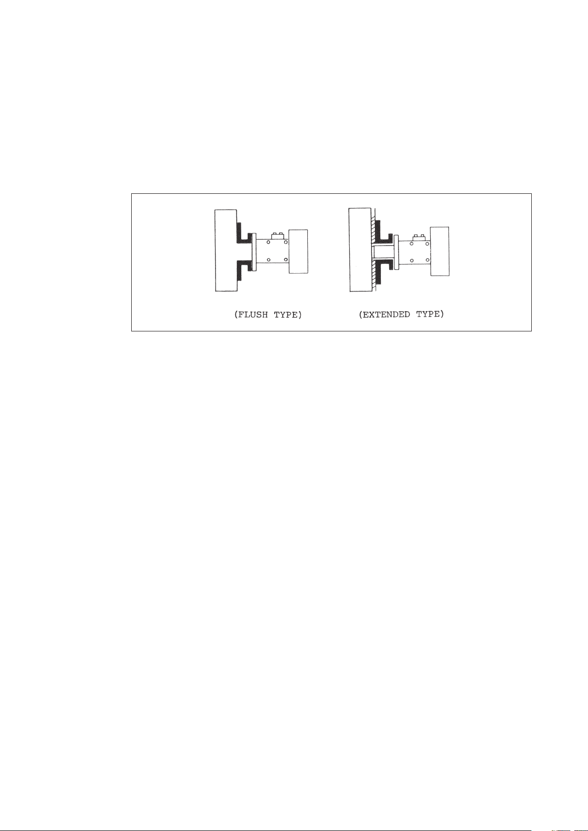
Some models of detectors have a flange incorporated with diaphragm for connection of the
high pressure line.
1-2. MODELS
Measured Pressures or Type
of Instrument
Standard Type, High/Medium
Differential Pressures
Standard Type, Low Differential
Pressures
Standard Type, Very Low
Differential Pressures
Flange Type Models KDP61/62
Remote-sealed diaphragm Type Models KDP71/72
High Working Pressure Type Models KDP81/82
1-3. INSTRUCTIONS FOR INSTRUMENTS (
Model Numbers of
Instruments Used in
Conjunction
Models KDP11/22
Models KFDB11/22
Model KDP33
Model KFDB33
Model KDP44
Model KFDB44
Models KFDB61/62
Models KFDB71/72
Models KFDBSl/82
Operator‘s Manual Used
in Conjunction
OM2-5220-1101 (KDP)
OM2-6220-0000 (KFDB)
TRANSMITTERS AND CONTROLLERS
)
USED IN CONJUNCTION
For the instructions for instruments used in conjunction, refer to respective Operator‘s
Manuals which cover the operating principles, service and unit replacement procedures, and
calibration and adjustment procedures of these instruments.
1
Page 6
Chapter 2. STRUCTURES OF METER BODIES
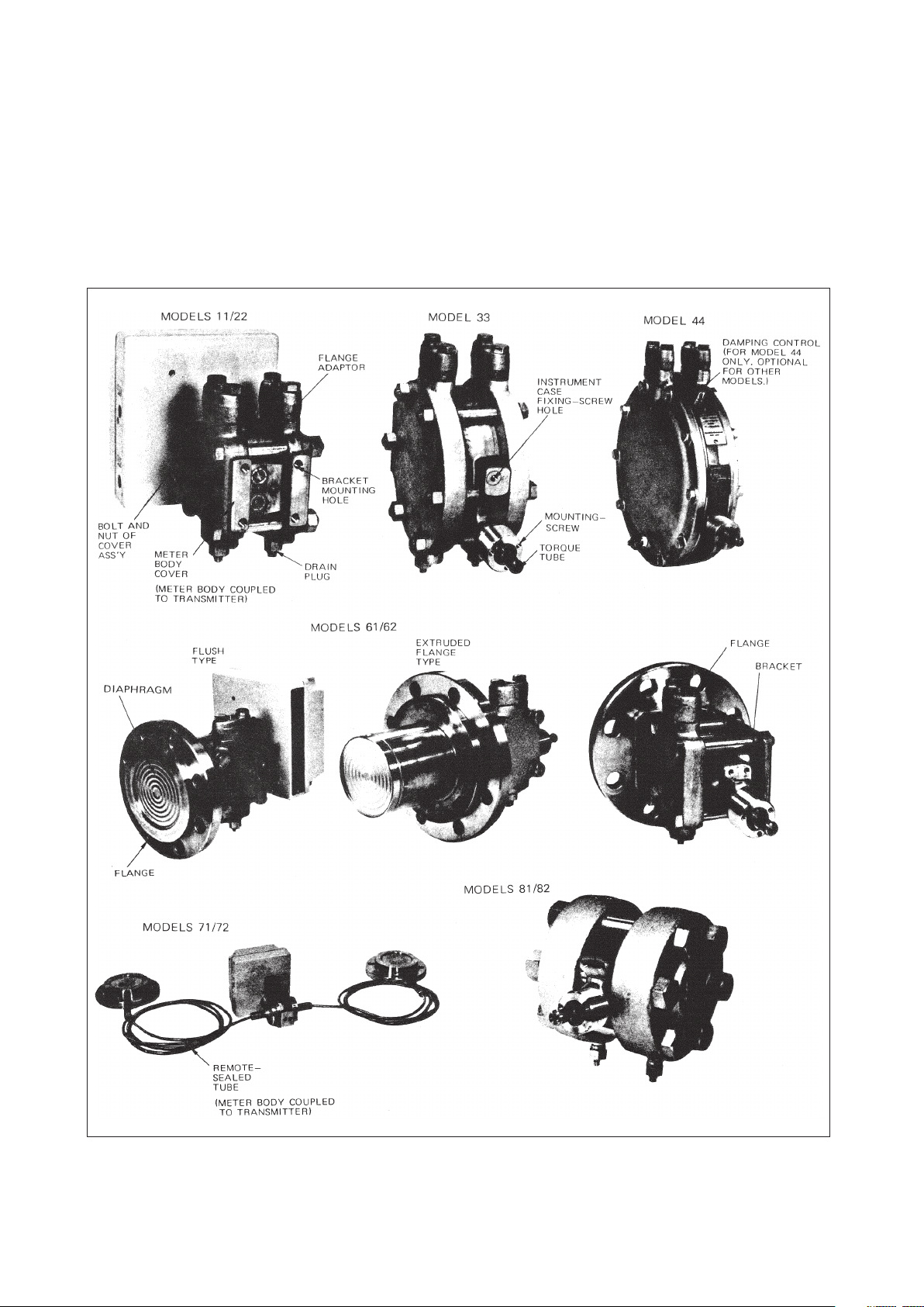
2-1. EXTERNAL VIEWS
Although external views of meter bodies differ by models as shown in Fig. 2-1, the bracket
mounting section and instrument connection section are identical for models 11/22, 71/72,
and for models 33/44, 81/82.
Fig. 2-1. External Views of Meter Bodies
2
Page 7
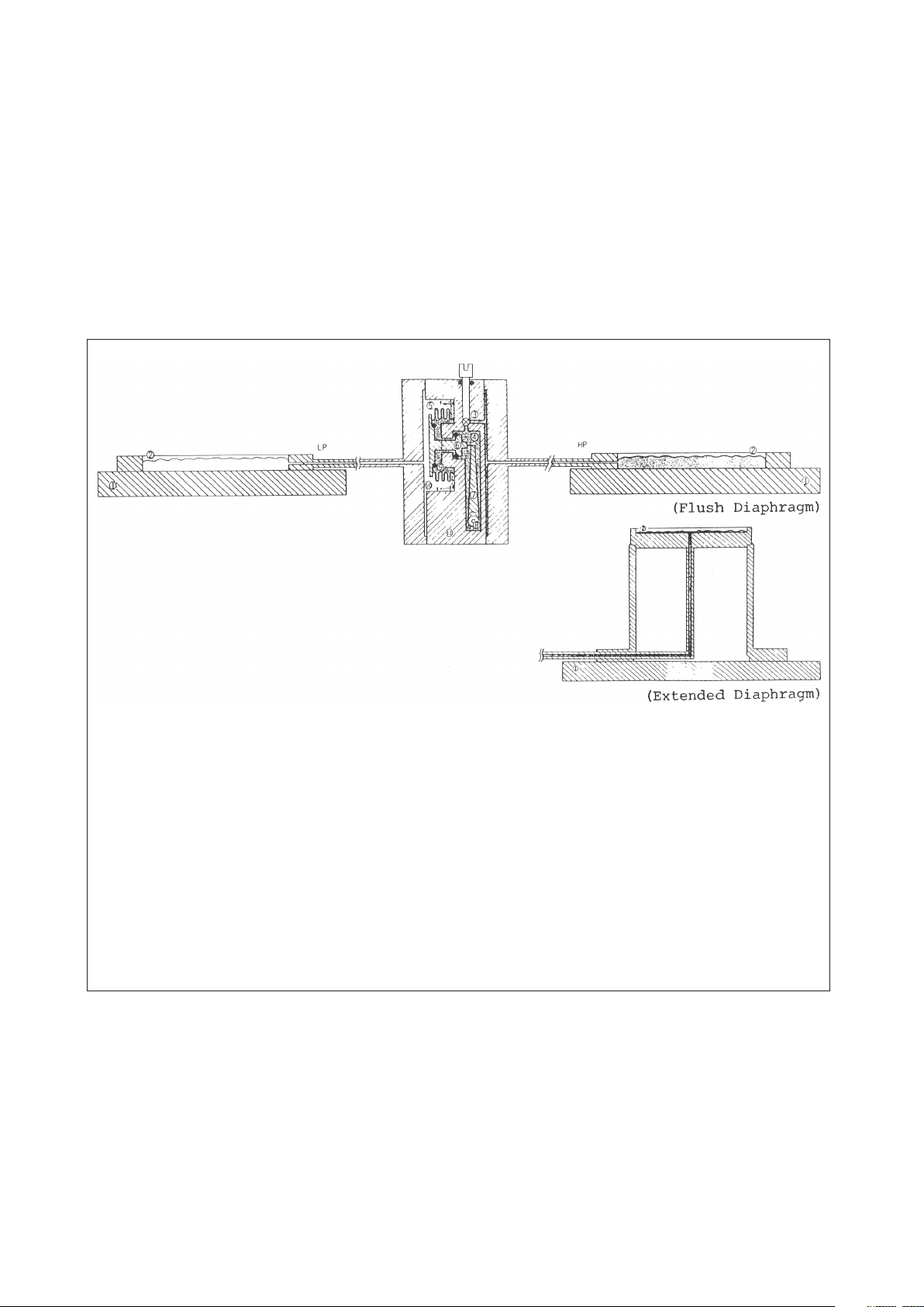
2-2. STRUCTURES AND OPERATING PRINCIPLES
The structures and operating principles of the meter bodies are covered in this section.
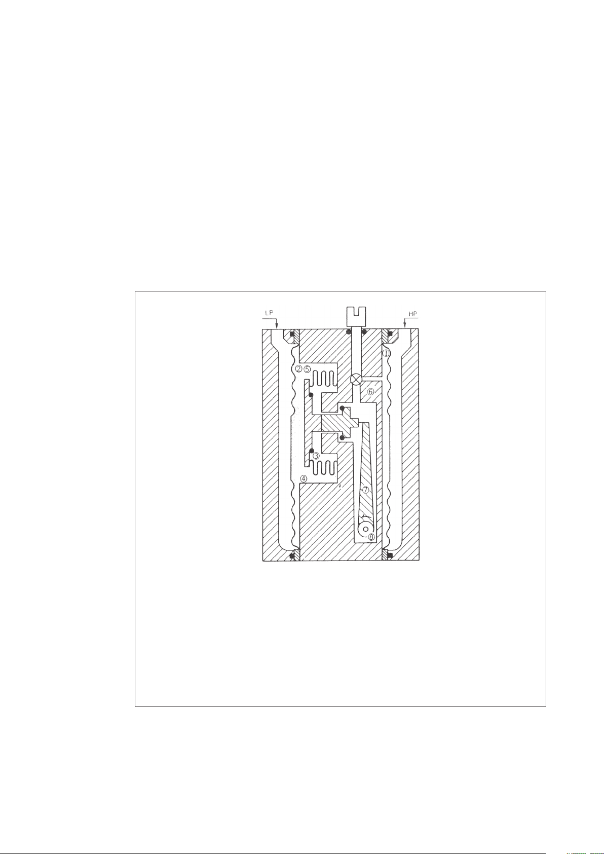
2-2-1. Models 11/12, 33, and 81/82
(a) The high and low process pressures (HP and LP) are fed via diaphragms (1) and (2) to
the center section (oil filled section) of the meter body. The HP acts on the differential
pressure detecting bellows from the right hand side (3) and the LP from the left hand side
(4). When in the equilibrium state (zero differential pressure state), identical forces are
exercised on both sides of the differential pressure detecting bellows (5).
(b) As the pressure of the HP side rises thereby increasing the differential pressure, the
differential pressure detecting bellows moves leftward. The movement of the bellows is fed
as a torque via the torque arm to the beam of the transmitter.
1 HP SEAL DIAPHRAGM
2 LP SEAL DIAPHRAGM
3 LIQUID FILL OF HP SIDE
4 LIQUID FILL OF LP SlUE
5 DIFFERENTIAL PRESSURE DETECTING BELLOWS
6 DAMPING CONTROL (OPTIONAL)
7 TORQUE ARM
8 TORQUE TUBE
Fig. 2-2. Operating Principle of Meter Body
3
Page 8
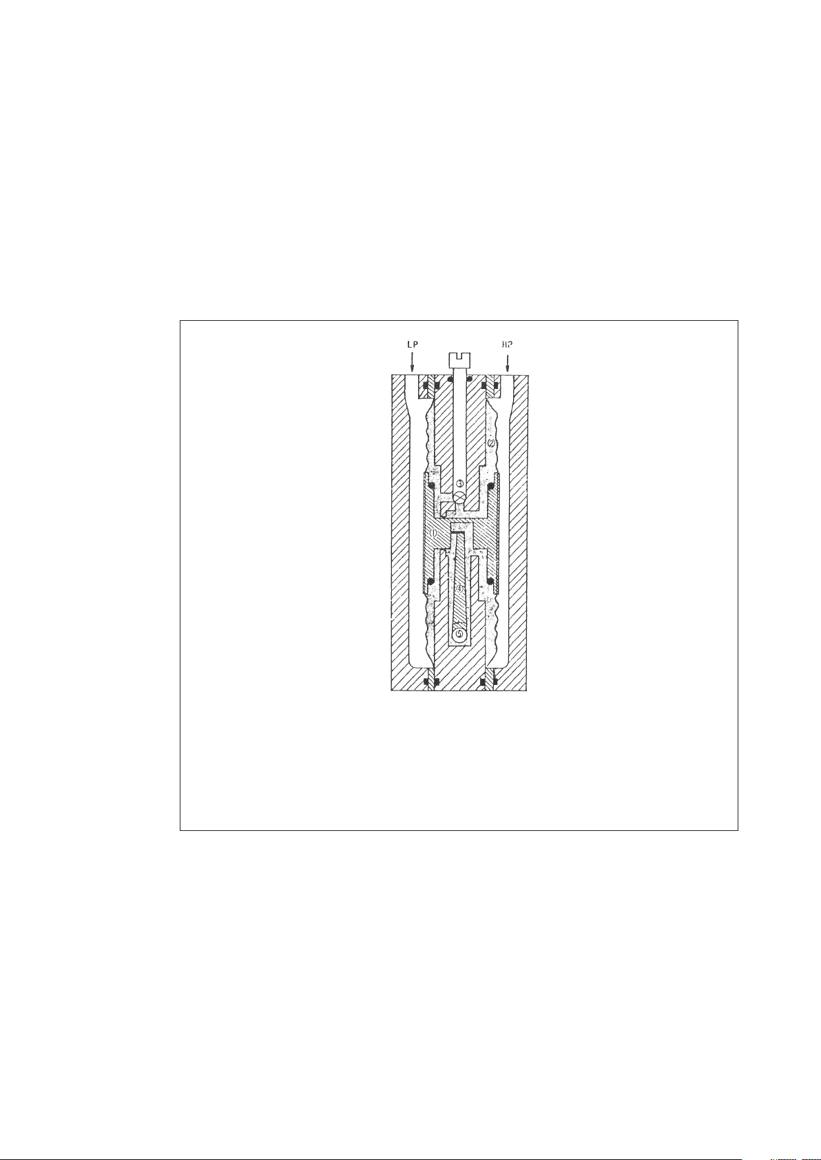
2-2-2. Model 44
(a) The high and low process pressures (HP and LP) are fed via the diaphragms and supports
(1) to the center section (silicone filled section) (2) of the meter body. The HP acts on
the pressure detecting diaphragm from the right hand side and the LP from the left hand
side. When in the equilibrium state (zero differential pressure state), identical forces are
exercised on both sides of the differential pressure detecting diaphragm.
(b) As the pressure of the HP side rises, the support moves leftward. The liquid fill flows
through the damping control (3). The movement of the diaphragm is fed as a torque via
the torque arm (4) to the beam of the transmitter.
1 DIAPHRAGM AND SUPPORT
2 LIQUID FILL
3 DAMPING CONTROL
4 TORQUE ARM
5 TORQUE TUBE
Fig. 2-3. Operating Principle of Meter Body
4
Page 9
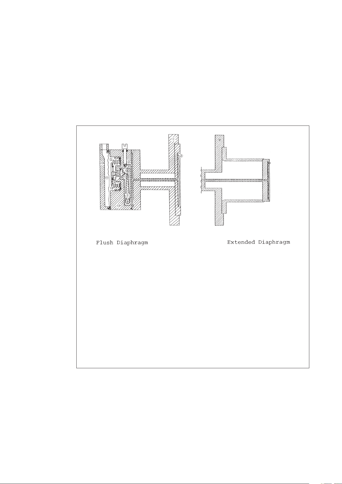
2-2-3. Models 61/62
(a) The high and low process pressures (HP and LP) are fed via diaphragms (2) and (11)
to the center section (silicone filled section) of the meter body. A pressure which is
proportional to the liquid head in the process vessel is fed via the seal diaphragm (2) and
liquid fill to the bellows (5) at the center section of the meter body.
(b) The bellows (5) moves in proportion to the liquid head pressure. The movement of
the bellows is fed as a torque via the plunger (6) and torque arm (7) to the beam of the
transmitter.
1 PROCESS CONNECTION FLANGE
2 SEAL DIAPHRAGM
3 DAMPING CONTROL (OPTIONAL)
4 HP LIQUID FILL (SILICONE)
5 BELLOWS
6 PLUNGER
7 TORQUE ARM
8 TORQUE TUBE
9 OVERLOAD SEAL
10 LP LIQUID FILL (SILICONE)
11 SEAL DIAPHRAGM
12 CENTER BODY
13 LP COVER
Fig. 2-4. Operating Principle of Meter Body
5
Page 10
2-2-4. Models 71/72
(a) The high and low process pressures (HP and LP) are fed via diaphragms (2) to the
center section (silicone filled section) (11) of the meter body. The HP is fed via the seal
diaphragm (2) and liquid fill (4) to the bellows (5) at the center section of the meter body.
The LP is fed bia the seal diaphragm (2) and liquid fill (10) to the bellows (5).
(b) The bellows (5) moves in proportion to the differential pressure between HP and LP.
The movement of the bellows is fed as a torque via the torque rod (8) to the beam of the
transmitter.
1 PROCESS CONNECTION FLANGE
2 SEAL DIAPHRAGM
3 DAMPING CONTROL
4 HP LIQUID FILL (SILICONE)
5 BELLOWS
6 PLUNGER
7 TORQUE ARM
8 TORQUE ROD
9 OVERLOAD SEAL
10 LP LIQUID FILL (SILICONE)
11 CENTER BODY
Fig. 2-5. Operating Principle of Meter Body
6
Page 11

Chapter 3. INSTALLATION
3-1. GENERAL
The meter body (detector), together with the instrument (transmitter) coupled to it, can be
installed on a 50 mm pipe stanchion by using the accessory bracket and U-shape bolt.
Model 61/62 meter body can be installed simply by fixing its flange to the process.
3-2. BRACKET AND BOLTS
There are two types of mounting brackets. The bracket and bolts for installation are supplied
accompanying each meter body.
3-3. PLACE OF INSTALLATION
When selecting a place of installation for the instrument, take into consideration the matters
related to instrument inspection, maintenance, longevity, and operation safety as follows:
(1) Select a place where temperature change is small (within the limits of -30 °C to +80 °C).
Avoid a place where the instrument is exposed to high temperature by radiation from a
source of heat.
When water is measured, pay attention to freezing which may cause damage to the meter
body. Provide appropriate means to guard against freezing.
(2) Select a place where is reasonably free from humidity and vibration.
(3) Be sure to provide spaces for inserting a screwdriver for adjustment and span change.
Fig. 3-1. Mounting Brackets
7
Page 12
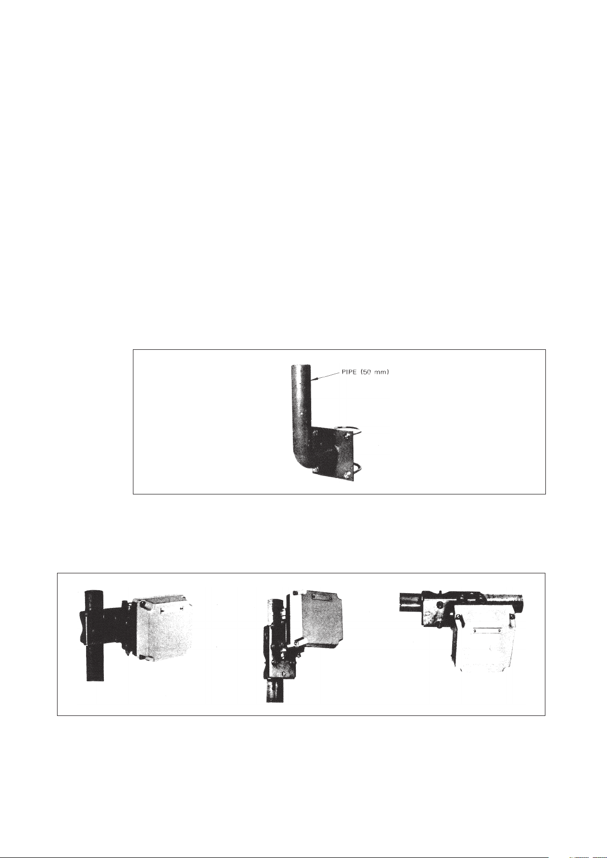
3-4. INSTALLATION METHOD
Install the meter body in such attitude that its diaphragm or bellows planes are made vertical.
3-4-1. Installation of Regular-type Meter Body
The meter body, together with the transmitter coupled to it, can be installed in either one of
the following methods:
• Pipe stanchion mount
• Process pipe mount
In either case, fix the meter body to a 50 mm vertical or horizontal pipe using the mounting
bracket and U-shape bolt. Fix the pipe securely to a foundation so that the pipe does not sway.
(See Fig. 3-3)
To install the meter body on a process pipe line, prepare brackets for mounting the 50 mm
pipe to the process pipe. (See Fig. 3-2)
When installing a remote-sealed type of meter body, exercise care not to sharply bend or twist
the capillary tube and not to damage the diaphragm.
Fig. 3-2. Example of Line Mount Bracket
Note: When installing the transmitter (meter body) on a 50 mm pipe, note that the order of
mountings (transmitter, bracket, and 50 mm pipe) differs depending on the mounting
direction.
Fig. 3-3. Installation Examples
8
Page 13
3-4-2. Installation of Model 61/62/71/72
Connect the detector flange to a process flange*. Tighten the bolts uniformly. The center of the
flange represents the zero point of the liquid level. (See Fig. 3-5) If the zero point is raised, the
head increases by a corresponding amount.
* Flange gaskets are to be prepared by customer.
When using a semi metallic gasket or a rubber gasket, select an one whose shape is
such that it with not be brought contact with the detector diaphragm (95 mm dia.).
Fig. 3-4. Connection to Process Vessel
3-4-3. Mounting Attitude
When the meter body is incorporated with a vent provision, install it in such attitude that vent
can be fully done. Entrapped drain and other foreign matter remaining in the meter body will
adversely affect measurement.
It is ideal to install the meter body so that its diaphragm or bellows planes are made vertical.
After installation is over, perform ZERO adjustment*.
* Refer to the section for calibration.
When a diaphragm pressure receiver type of meter body (Models 61/62, 71/72) is used for
liquid level measurement, the zero point will be as shown in Fig. 3-5. Calculate the output
referring to the dimensions and calibrate the instrument accordingly.
9
Page 14

Note: For the portion from the minimum liquid level (0 % level) to a height of 25 mm, the
output is not linearly proportional to the liquid level.
3-5. PRESSURE PIPING
3-5-1. Models 11/22/33/44/81/82
(1) Piping method (tapping pressure connection method) may differ depending on the
installation position of the instrument and the conditions of the process pipe line. In
general, a manifold piping method or a manifold valve method is used. (The manifold
valve is available as an option.)
Fig. 3-5. Zero Point of Diaphragm
Fig. 3-6. Manifold Valve
10
Page 15

(2) When in flow measurement and the meter body is installed lower than the pipe line, it is
recommended to provide blow pipes.
Fig. 3-7. Blow Piping
(3) For the pressure connection piping from the pressure tap position to the transmitter,
provide a gradient so that drain is returned through the tapping position to the process
line.
(4) Regarding the process pressure connection ports of the meter body, the high pressure side
(HP) is located to the right and the low pressure side (LP) to the left as viewed from the
front of the meter body (transmitter).
If the high pressure side and low pressure side are required to be used in the reverse from
the viewpoint of piping, use a Reverse Unit*.
* The Reverser Unit is available as an option. This unit cannot be used for Model 81/82.
(5) For the pipes for pressure tapping from the process pipe, use pressure pipes of appropriate
schedule number and nominal thickness. A typical example in 1/2-inch Schedule 80 steel
pipe. For measurement of water or steam, copper pipes are used in general.
Examples of pressure piping are shown in Fig. 3-8.
11
Page 16

Fig. 3-8. Pressure Piping for Flow Measurement
(6) To change connections to process:
If it is required to change process connections (vent and drain) between upper and lower
positions, remove the two flanges of the connection ports and also the plugs of vent and
drain, and change the positions between upper and lower. (Refer to the overall dimension
drawings.)
(7) Pressure tapping methods:
For tapping methods of process pressures, refer to the illustrations given in this section.
The "H" is the high pressure side of the meter body and the "L" is the low pressure side.
They are marked on the meter body.
12
Page 17

Fig. 3-9. Connections of Pressure Pipes for Liquid Level Measurement
The liquid level corresponding to the difference between the 0 % level and the center of
the meter body is given from the beginning. In the case of A or B shown in Fig. 3-9, make
compensation (provide an elevation) for the corresponding amount and set the output at 0.2 to
2
1.0 kgf/cm
for liquid level 0 to 100 %. In the case of C, a pressure corresponding to the head
of the seal liquid is applied to the low pressure side to the state of A or B and consequently the
high/low relationship between the H side and L side of the meter body is in the reverse.
Therefore, compensation (suppression) should be made for the seal liquid head for the
difference between 100 % level position and 0 % level position.
For "elevation" and "suppression", refer to Section 3-6.
3-5-2. Connection of Flange Type Meter Body to Process
Fig. 3-10. Process Connections of Model 61/62 for Liquid Level Measurement
13
Page 18

Fig. 3-11. Process Connections of Model 71/72 for Liquid Level Measurement
Fig. 3-12. Pressure Tapping for Model 71/72 for Flow Measurement
(1) Fix the flanges of the meter body to those of the process side by using gaskets and bolts.
Be sure to uniformly and securely tighten the bolts in order to prevent leak.
Lay the capillary tubes in such manner that they are less subjected to large temperature
change. Fix them so that they do not move.
14
Page 19

(2) Regarding the flange of the low pressure side when in level measurement of an open
tank, fix it securely at a position where it will be less subjected to temperature change
and mechanical vibration. Position the LP side flange at a height lower than that of the
minimum liquid level.
Regarding the seal diaphragm, protect it so that it is not damaged and pay attention so
that no drain is entrapped on it and no dust is collected on it.
(3) For flow measurement, tapping for the differential pressure must be done in the "pipe tap"
system. Therefore, locate the high-pressure-side tap at a location of 2.5D (D denotes the
inside diameter of the process pipe) from the upstream side of the orifice and locate the
low-pressure-side tap at a location of 8D from the downstream side of the orifice.
The tapping connection is of a 3-inch flange connection type. The flanges of the extension seal
type of meter body can be directly used as the tapping flanges.
3-6. ELEVATION AND SUPPRESSION
3-6-1. Definitions of Elevation and Suppression
The terms "elevation" and "suppression" as used inthis publication are defined as follows:
Elevation: Synonymous with "suppressed zero range"
An input range whose low end value is higher than zero.
For example, a range of 20 to 100.
Suppression: Synonymous with "elevated zero range"
An input range whose low end value is lower than zero.
For example, a range of -20 to 0.
3-6-2. Setting of Elevation/Suppression
For setting of elevation/suppression, refer to Section "CALIBRATION AND ADJUSTMENT"
of Operator's Manual for Pneumatic Transmitter OM2-522-000.
Note: The specific-gravity of the liquid fill of Models 71/72 is 0.935 at 20 °C. (For temperature
compensation, use a factor of 0.001/°C)
Fig. 3-13. Elevation and Suppression
15
Page 20

Open Tank Closed tank (without seal
liquid)
Close tank (with seal liquid)
11, 22,
33, 44,
81, 82
Provide suppression corresponding to differential level between
zero liquid level and center of pressure receiver multiplied by
specific-gravity of liquid measured.
61, 62 No elevation/suppression is needed if the imaginary zero liquid
level* conforms with center position of diaphragm of flange
connection section.
* Refer to Section 3-4-3
If the zero liquid level is higher than center position of
diaphragm, provide elevation by an amount corresponding to
the height multiplied specific-gravity of liquid measured.
71, 72 Provide elevation by an
amount corresponding to
difference between center
positions of HP and LP flange
diaphragms multiplied by
specific-gravity of seal liquid.
Provide suppression by an
amount corresponding to
difference between center
position of HP and LP flange
diaphragms multiplied by
specific-gravity of seal liquid.
Provide suppression by amount
corresponding to measuring liquid
level multiplied by specific-gravity of
measured liquid (seal liquid).
A
Subtract from suppression the
difference between zero liquid level
and center position of diaphragm as
elevation.
B C
Not applicable
When zero liquid level is
higher than center position
of HP flange diaphragm,
add as elevation an amount
corresponding to the height
multiplied by specific-gravity
of measured liquid.
When zero liquid level is
higher than center position
of HP flange diaphragm,
subtract from the above
suppression an amount
corresponding to the height
multiplied by specificgravity of measured liquid as
elevation.
D E
16
Page 21

Fig. 3-14. Calculation of Elevation/Suppression Values
17
Page 22

Chapter 4. OPERATION METHOD
The meter body, together with the transmitter coupled to it, starts operating as the air supply
and process input are fed to it. (It is recommendable to check the operation of the transmitter
before starting the running operation.)
4-1. DIFFERENTIAL PRESSURE (FLOW) TRANSMISSION
The operation method (start up procedure) here is described assuming that manifold valves
and blow piping are prepared as shown in Section 3-5-1 of Part "Chapter 3. INSTALLATION."
Of Model 71 or 72, operation is ready when its installation is over.
(1) Check that piping is correctly done.
(2) Unless self drain or self vent piping is done, liquid or gas will be entrapped in the
measuring chambers and pressure connection pipes, thereby causing measurement errors.
Be sure to drain out or vent out such liquid or gas. The same applies regardless of whether
manifold valves are used or manifold piping is done. For the procedure, refer to Part
"Chapter 5. INSPECTION AND MAINTENANCE."
(3) Zero point check:
When the instrument has become the measuring state, set a receiver instrument and
check and adjust the zero point as follows: Of the manifold valves, close the stop valves of
both high and low pressure sides and then open the equalizer valve.
Next, open the stop valve of the high pressure side alone so that the process pressure of
the high side alone is applied to both high and low pressure chambers of the meter body.
Under this state, check the zero point. After the zero point check is complete, close the
equalizer valve and then open the stop valve of the low pressure side.
(4) Operating procedure:
To start operating the meter body from the state that all valves are closed, open or close
them in the due order as noted in the following:
(1) Open the equalizer valve.
(2) Open the stop valve of low pressure side tapping-pipe and the stop valve of low
pressure side of manifold.
(3) Open the stop valve of high pressure side tapping-pipe and the stop valve of high
pressure side of manifold.
(4) Close the equalizer valve.
18
Page 23

4-2. LIQUID LEVEL TRANSMISSION
The operation method (start up procedure) here is described assuming that the meter body is
installed as shown in Sections 3-5-1 Fig. 3-9 and 3-5-2 of Part "Chapter 3. INSTALLATION".
No operation procedure is needed for the process connections with flanges (diaphragms). Of
Model 71 or 72, operation is ready when its installation is over.
(1) Check that piping is correctly done.
(2) Unless self drain or self vent piping is done, liquid or gas will be entrapped in the
measuring chambers and pressure connection pipes, thereby causing measurement
errors. Be sure to drain out or vent out such liquid or gas. For the procedure, refer to Part
"Chapter 5. INSPECTION AND MAINTENANCE."
(3) Zero point check:
When the instrument has become the measuring state, set a receiver instrument and
check and adjust the zero point.
(4) Open the stop valves and start operating the instrument. When seal liquid is used, full the
low pressure side tapping-pipe with seal liquid.
19
Page 24

Chapter 5. INSPECTION AND MAINTENANCE
For routine inspection and maintenance, pay attention to the following:
5-1. CHECK FOR LEAK FROM PIPING
Check that there is no leak in the piping from the pressure tap points to the meter body. If any
loose connections are found, tighten them securely.
5-2. BLOW AND CLEANING OF METER BODY AND PIPING
To maintain constantly the instrument at its best performances meeting its specification
accuracy, keep clean the meter body and its piping. If sediment or other foreign matters are
entrapped in the pressure chambers of the meter body, measuring errors may be caused. To
blow and clean the meter body and piping, proceed as mentioned in the following.
5-2-1. Blow Procedure
5-2-1-1. When No Blow Pipes are Provided
(1) Close the stop valve of the high pressure side tapping pipe and that of the high pressure
side of the manifold valve.
(2) Check that the equalizer valve is closed.
(3) Close the stop valve of the low pressure side tapping pipe and that of the low pressure
side of the manifold valve.
(4) Slowly open the both side vent plugs to release pressure. And shut them.
(5) Open the stop valve of the high pressure side of the manifold valve and that of the high
pressure side tapping pipe.
(6) Open the equalizer and blow the piping via the high pressure side vent plug.
(7) Close the equalizer valve, the stop valve of the high pressure side of the manifold valve,
and that of the high pressure side tapping pipe.
(8) Open the stop valve of the low pressure side of the manifold valve and that of the low
pressure side tapping pipe.
(9) Open the equalizer valve and blow the piping from the low pressure side vent hole.
(10) Close all valve.
(11) Start operating the instrument following the procedure explained in Part "Chapter 4.
OPERATION METHOD."
20
Page 25

5-2-1-2. When Blow Pipes are Provided (See Fig. 3-7 of Section 3-5, Part "Capter 3.
INSTALLATION.")
(1) Close the stop valve of the high pressure side of the manifold valve.
(2) Close the stop valve of the low pressure side of the manifold valve.
(3) Slowly open the blow valves of both high and low pressure sides to drain out sediment or
other entrapped substance.
(4) Close the blow valves of both high and low pressure sides.
(5) Open the stop valve of the low pressure side of the manifold valve.
(6) Open the stop valve of the high pressure side of the manifold valve.
5-2-1-3. Blow of Model 61/62 Liquid Level Meter
(1) For an open tank liquid level meter, drain out liquid by loosening the drain plug at the
bottom of the low pressure side cover at appropriate intervals.
(2) For a closed tank liquid level meter of gas sealed type, at first close the stop valve of the
low pressure side tapping-pipe and then open the blow valve to vent gas at appropriate
intervals.
(3) For a closed tank liquid level meter of liquid sealed type, check the seal liquid level and
replace seal liquid at appropriate intervals.
To replace seal liquid, proceed as follows: Close the stop valve of the low pressure side
tapping-pipe, open the blow valve, and loosen the drain plug to drain out seal liquid. Next,
tighten the drain plug, feed seal liquid from the valve for blow until seal liquid overflows
from the blow valve, close the blow valve, and then open the stop valve.
5-2-2. Cleaning of Meter Body
After the blowing of the piping as described in 2.1 is over, clean the meter body as described
below. Of Models 71/72 and 61/62, clean only the diaphragms outsides of flanges.
(1) Remove the covers of the meter body by removing their clamping-bolts.
(2) Clean the diaphragm and the insides of the covers using soft brush and detergent. When
doing this, be extremely careful not to deform or damage the diaphragm.
(3) When reassembling the covers, replace gaskets with new ones as required. (Refer to 3-4-2)
(4) Fix the clamping-bolts of the covers with the specified tightening torques as shown in the
following table.
21
Page 26

Model Tightening torque (kgf∙cm) Material of Clamping-bolts
When new
gasket is used
11/22, 61/62 450 300 Chrome molybdenum steel
33 450 300 Chrome molybdenum steel
44 200 Chrome molybdenum steel
81/82 1400 Chrome molybdenum steel
5-2-3. Notes for Use in Freezing Season
When the transmitter used for measurement of water or other freezable liquid is paused
in a freezing season or area, loosen the drain plugs and drain out liquid from the pressure
chambers to prevent freezing.
When gasket is
re-used
22
Page 27

Page 28

Terms and Conditions
We would like to express our appreciation for your purchase and use of Azbil Corporation’s products.
You are required to acknowledge and agree upon the following terms and conditions for your purchase of Azbil Corporation’s products (system
products, field instruments, control valves, and control products), unless otherwise stated in any separate document, including, without limitation,
estimation sheets, written agreements, catalogs, specifications and instruction manuals.
1. Warranty period and warranty scope
1.1 Warranty period
Azbil Corporation’s products shall be warranted for one (1) year from the date of your purchase of the said products or the delivery of the
said products to a place designated by you.
1.2 Warranty scope
In the event that Azbil Corporation’s product has any failure attributable to azbil during the aforementioned warranty period, Azbil
Corporation shall, without charge, deliver a replacement for the said product to the place where you purchased, or repair the said
product and deliver it to the aforementioned place. Notwithstanding the foregoing, any failure falling under one of the following shall
not be covered under this warranty:
(1) Failure caused by your improper use of azbil product (noncompliance with conditions, environment of use, precautions, etc. set
forth in catalogs, specifications, instruction manuals, etc.);
(2) Failure caused for other reasons than Azbil Corporation’s product;
(3) Failure caused by any modification or repair made by any person other than Azbil Corporation or Azbil Corporation’s
subcontractors;
(4) Failure caused by your use of Azbil Corporation’s product in a manner not conforming to the intended usage of that product;
(5) Failure that the state-of-the-art at the time of Azbil Corporation’s shipment did not allow Azbil Corporation to predict; or
(6) Failure that arose from any reason not attributable to Azbil Corporation, including, without limitation, acts of God, disasters, and
actions taken by a third party.
Please note that the term “warranty” as used herein refers to equipment-only-warranty, and Azbil Corporation shall not be liable for any
damages, including direct, indirect, special, incidental or consequential damages in connection with or arising out of Azbil Corporation’s
products.
2. Ascertainment of suitability
You are required to ascertain the suitability of Azbil Corporation’s product in case of your use of the same with your machinery,
equipment, etc. (hereinafter referred to as “Equipment”) on your own responsibility, taking the following matters into consideration:
(1) Regulations and standards or laws that your Equipment is to comply with.
(2) Examples of application described in any documents provided by Azbil Corporation are for your reference purpose only, and
you are required to check the functions and safety of your Equipment prior to your use.
(3) Measures to be taken to secure the required level of the reliability and safety of your Equipment in your use
Although azbil is constantly making efforts to improve the quality and reliability of Azbil Corporation’s products, there exists
a possibility that parts and machinery may break down. You are required to provide your Equipment with safety design such
as fool-proof design,*
physical injuries, fires, significant damage, and so forth. Furthermore, fault avoidance,*3 fault tolerance,*4 or the like should be
incorporated so that the said Equipment can satisfy the level of reliability and safety required for your use.
*1. A design that is safe even if the user makes an error.
*2. A design that is safe even if the device fails.
*3. Avoidance of device failure by using highly reliable components, etc.
*4. The use of redundancy.
3. Precautions and restrictions on application
3.1 Restrictions on application
Please follow the table below for use in nuclear power or radiation-related equipment.
Nuclear power quality*5 required Nuclear power quality*5 not required
Within a radiation
controlled area*
Outside a radiation
controlled area*
Cannot be used (except for limit switches for
6
nuclear power*7)
Cannot be used (except for limit switches for
6
nuclear power*7)
1
and fail-safe design*2 (anti-flame propagation design, etc.), whereby preventing any occurrence of
Cannot be used (except for limit switches for
nuclear power*7)
Can be used
*5. Nuclear power quality: compliance with JEAG 4121 required
*6. Radiation controlled area: an area governed by the requirements of article 3 of “Rules on the Prevention of Harm from
Ionizing Radiation,” article 2 2 4 of “Regulations on Installation and Operation of Nuclear Reactors for Practical Power
Generation,” article 4 of “Determining the Quantity, etc., of Radiation-Emitting Isotopes,”etc.
*7. Limit switch for nuclear power: a limit switch designed, manufactured and sold according to IEEE 382 and JEAG 4121.
Any Azbil Corporation’s products shall not be used for/with medical equipment.
The products are for industrial use. Do not allow general consumers to install or use any Azbil Corporation’s product. However, azbil
products can be incorporated into products used by general consumers. If you intend to use a product for that purpose, please contact
one of our sales representatives.
3.2 Precautions on application
you are required to conduct a consultation with our sales representative and understand detail specifications, cautions for operation,
and so forth by reference to catalogs, specifications, instruction manual, etc. in case that you intend to use azbil product for any purposes
specified in (1) through (6) below. Moreover, you are required to provide your Equipment with fool-proof design, fail-safe design, antiflame propagation design, fault avoidance, fault tolerance, and other kinds of protection/safety circuit design on your own responsibility
to ensure reliability and safety, whereby preventing problems caused by failure or nonconformity.
Page 29

(1) For use under such conditions or in such environments as not stated in technical documents, including catalogs, specification,
and instruction manuals
(2) For use of specific purposes, such as:
* Nuclear energy/radiation related facilities
[When used outside a radiation controlled area and where nuclear power quality is not required]
[When the limit switch for nuclear power is used]
* Machinery or equipment for space/sea bottom
* Transportation equipment
[Railway, aircraft, vessels, vehicle equipment, etc.]
* Antidisaster/crime-prevention equipment
* Burning appliances
* Electrothermal equipment
* Amusement facilities
* Facilities/applications associated directly with billing
(3) Supply systems such as electricity/gas/water supply systems, large-scale communication systems, and traffic/air traffic control
systems requiring high reliability
(4) Facilities that are to comply with regulations of governmental/public agencies or specific industries
(5) Machinery or equipment that may affect human lives, human bodies or properties
(6) Other machinery or equipment equivalent to those set forth in items (1) to (5) above which require high reliability and safety
4. Precautions against long-term use
Use of Azbil Corporation’s products, including switches, which contain electronic components, over a prolonged period may degrade
insulation or increase contact-resistance and may result in heat generation or any other similar problem causing such product or switch
to develop safety hazards such as smoking, ignition, and electrification. Although acceleration of the above situation varies depending
on the conditions or environment of use of the products, you are required not to use any Azbil Corporation’s products for a period
exceeding ten (10) years unless otherwise stated in specifications or instruction manuals.
5. Recommendation for renewal
Mechanical components, such as relays and switches, used for Azbil Corporation’s products will reach the end of their life due to wear by
repetitious open/close operations.
In addition, electronic components such as electrolytic capacitors will reach the end of their life due to aged deterioration based on
the conditions or environment in which such electronic components are used. Although acceleration of the above situation varies
depending on the conditions or environment of use, the number of open/close operations of relays, etc. as prescribed in specifications
or instruction manuals, or depending on the design margin of your machine or equipment, you are required to renew any Azbil
Corporation’s products every 5 to 10 years unless otherwise specified in specifications or instruction manuals. System products, field
instruments (sensors such as pressure/flow/level sensors, regulating valves, etc.) will reach the end of their life due to aged deterioration
of parts. For those parts that will reach the end of their life due to aged deterioration, recommended replacement cycles are prescribed.
You are required to replace parts based on such recommended replacement cycles.
6. Other precautions
Prior to your use of Azbil Corporation’s products, you are required to understand and comply with specifications (e.g., conditions and
environment of use), precautions, warnings/cautions/notices as set forth in the technical documents prepared for individual Azbil
Corporation’s products, such as catalogs, specifications, and instruction manuals to ensure the quality, reliability, and safety of those
products.
7. Changes to specifications
Please note that the descriptions contained in any documents provided by azbil are subject to change without notice for improvement
or for any other reason. For inquires or information on specifications as you may need to check, please contact our branch offices or
sales offices, or your local sales agents.
8. Discontinuance of the supply of products/parts
Please note that the production of any Azbil Corporation’s product may be discontinued without notice. After manufacturing is
discontinued, we may not be able to provide replacement products even within the warranty period.
For repairable products, we will, in principle, undertake repairs for five (5) years after the discontinuance of those products. In
some cases, however, we cannot undertake such repairs for reasons, such as the absence of repair parts. For system products, field
instruments, we may not be able to undertake parts replacement for similar reasons.
9. Scope of services
Prices of Azbil Corporation’s products do not include any charges for services such as engineer dispatch service. Accordingly, a separate
fee will be charged in any of the following cases:
(1) Installation, adjustment, guidance, and attendance at a test run
(2) Maintenance, inspection, adjustment, and repair
(3) Technical guidance and technical education
(4) Special test or special inspection of a product under the conditions specified by you
Please note that we cannot provide any services as set forth above in a nuclear energy controlled area (radiation controlled area) or at a
place where the level of exposure to radiation is equivalent to that in a nuclear energy controlled area.
AAS-511A-014-10
Page 30

Page 31

Document Number:
OM2-5220-1100
Document Name:
Date:
Issued/Edited by:
Dierential Pressure Detectors (Meter Bodies)
Model KDP/KFDB
User's Manual
4th edition: Jan. 2020
Page 32

 Loading...