

Page 1

Multifunction
Pulse-to-Pneumatic
Pressure Converter
Model J-APN11
CM2-APN100-2001
User's Manual
Page 2

Copyright, Notices and Trademarks
1997-2015 Azbil Corporation All Rights Reserved.
While this information is presented in good faith and believed to be accurate,
Azbil Corporation disclaims the implied warranties of merchantability and
fitness for a particular purpose and makes no express warranties except as
may be stated in its written agreement with and for its customer.
In no event is Azbil Corporation liable to anyone for any indirect, special or
consequential damages, The information and specifications in this document
are subject to change without notice.
Page 3
For Safe Operation
Preface
Checkup
Message Con-
ventions
Safe equipment use requires accurate installation, operation and maintenance. Be
sure to read and understand the section on "Important Items" thoroughly before
attempting installation, operation or maintenance.
• Upon arrival, check equipment specifications and ensure there is no damage in
transit. Equipment is tested by strict quality control programs before shipment.
For oversights in quality or specifications, contact Azbil Corporation, providing
equipment information and serial No.
• The nameplate is on the top of the case.
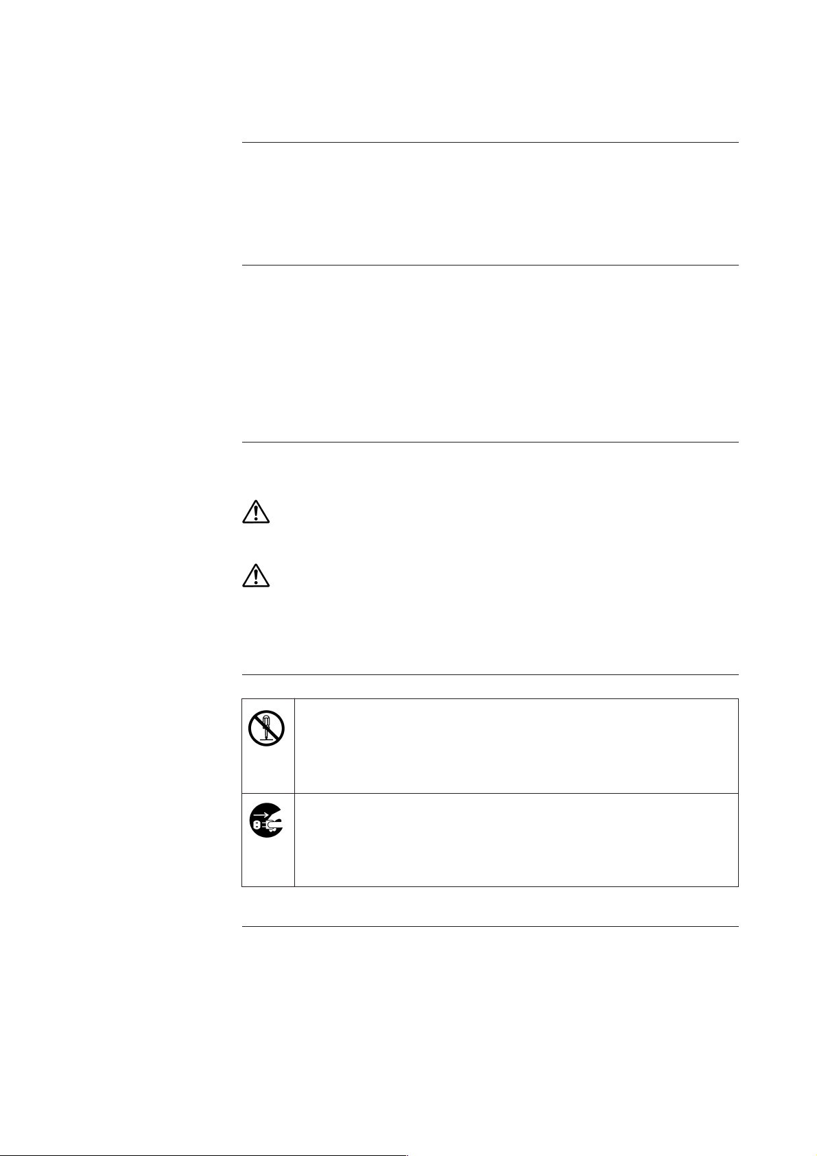
This manual uses the following message conventions:
Warning
Personal injury could occur if procedures are not
followed closely.
Other indications
Caution
An illustration in a white circle with a back slash ○ indicates an action
to avoid.
A detailed explanation of the action is given in the circle or near the
mark.
An illustration in a black circle ● indicates an instruction regarding a
specific action to avoid.
A detailed explanation is given in the circle. The illustration at left
means to pull the plug from the socket.
Minor personal injury could occur if procedures are not
followed closely. Inconvenience such as equipment
damage could occur if procedures are not followed
closely.
Page 4
Notes on Handling
Notes
on Installation
Notes on
Wiring
Warning
• Do not use equipment outside the range determined in the specifications. Serious accident could occur.
Caution
• After installation, do not step or climb on this product. Equipment
may be damaged or personal injury occur.
• Do not press or hit door glass. Glass may be broken or personal
injury occur.
• Ground correctly. Incomplete grounding violates rules and may
cause output errors.
• Equipment is heavy. Wear safety shoes.
Warning
• Electrical shock may occur if working with wet hands or power on.
Notes on
Maintenance
Caution
• Perform wiring according to wiring specifications. Incorrect wiring
may damage equipment or lead to operation errors.
• Operate the power supply according to specifications. Incorrect
operation may damage equipment.
Caution
• Do not modify equipment. Modification may damage equipment.
Page 5

Contents
1. Outline ....................................................................................................... 1-1
2. Converter Configuration and Parts ........................................................... 2-1
3. Installation and Operation ......................................................................... 3-1
3-1 Installation ................................................................................................... 3-1
3-2 Operation .................................................................................................... 3-1
3-3 Connection .................................................................................................. 3-2
3-4 Wiring Procedure ........................................................................................ 3-3
4. Adjustment and Setting ............................................................................. 4-1
4-1 Preparation .................................................................................................. 4-1
4-2 Adjustment of Pneumatic Pressure Output (Figure 4-2) ............................. 4-2
4-3 Adjustment of Current Output (Figure 4-3) .................................................. 4-4
4-4 Setting Pneumatic Pressure Monitor ........................................................... 4-5
4-5 Setting Output Speed .................................................................................. 4-6
4-6 Manual Operation (with A/M switch) ............................................................ 4-7
5. Parts List ................................................................................................... 5-1
6. Maintenance ............................................................................................. 6-1
6-1 Regular Maintenance .................................................................................. 6-1
6-2 Periodical Maintenance and Checking ........................................................ 6-1
Page 6

1. Outline
The J-APN 11 Multifunction Rulse-to-Pneumatic Pressure Converter responds to up (upward)and down
(downward)pulse signals. It drives pulses and a (four-phase) motor to send out pneumatic pressure
signals of 20 to 100[kPa] and current signals of 4 to 20 [mA] DC via a nozzle and a flapper mechanism.
In case of power failure, the converter automatically keeps the pneumatic pressure signal at its pre-failure
position (provided that the pneumatic source is in normal operation).
1 - 1
Page 7
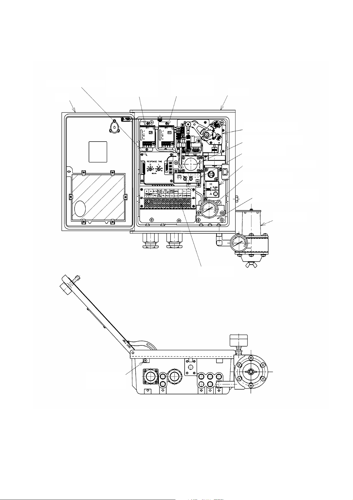
2. Converter Configuration and Parts
Main printed plate
assembly
Door
S/M pneumatic
pressure drop
monitor
M1 Pneumatic
pressure signal
monitor
Case
Mechanical part assembly
Pilot valve installed
P/I unit
Manual operation mechanism
(*)
Output pneumatic pressure
indicator
Relay block for internal
piping
Air set
Customer
terminals
External ground
terminal (M4)
(*): If manual operation is not used, a pneumatic pressure signal monitor (M2) can be installed.
Figure 2-1 Converter configuration and parts
2 - 1
Page 8
3. Installation and Operation
3-1. Installation
Mount the converter securely on a 2-inch pipe or on a wall. (refer to Specification Sheets
:SS2-APN100-0100, the figure for externaldimensions.)
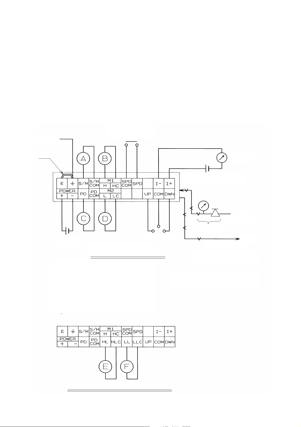
3-2. Operation
Complete wiring and piping according to Figure 3-2-1. Warm up the converter for about 30 minutes
before operating.
For air supply, please use the prescribed instrumentation air.
Class 3
grounding
(*1)
Power supply
24V DC
Contact for changing speed
High speed when contact is on
Contact for pulse input
Distribution frame with two pneumatic
pressure monitors
Contacts
A: Supplied air drop monitor
B: Output pneumatic pressure signal monitor
(high)
C: Power supply down monitor
D: Output pneumatic pressure signal monitor
(low)
E: High
F: Low
Ammeter
(4 to 20mA)
Power supply for current
output 24VDC
Supplied air
200 to 990kPa
Air set
Output air
20 to 100kPa
Apply load of ø4 and 3m +20cc.
(*1): Remove jumper plate when testing
withstand voltage or insulation
resistance.
Distribution frame with limit contact output
Figure 3-2-1 Customer terminal wiring and air piping
3 - 1
Page 9
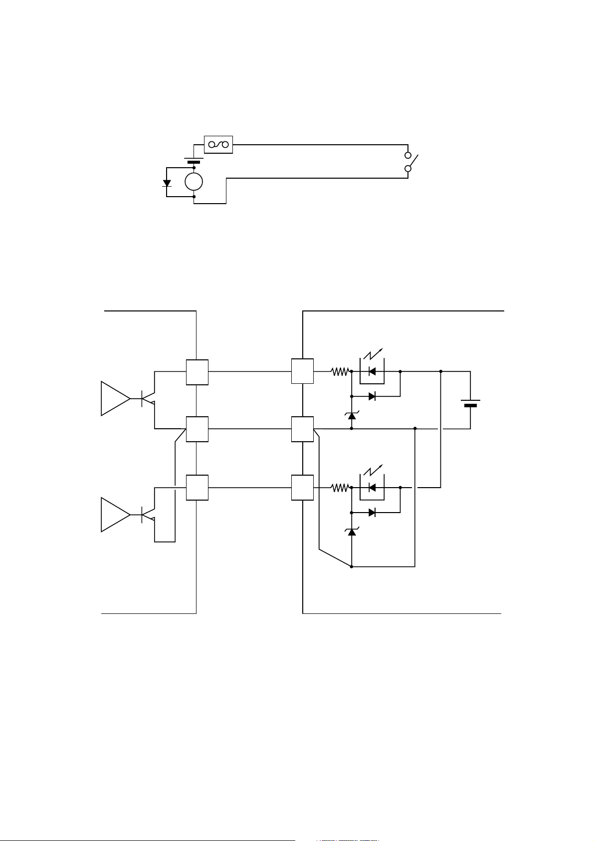
3-3. Connection
(a) Contact output
Fuse or MCB
Figure 3-3-1
Combine the contact with a surge suppression device for safety.
(b) UP/down signals
UP
Amplifer
UP
Amplifer
Output side
UP
COM
DWN
J-APN
Figure 3-3-2 Connection method
24V DC
24V DC
For isolated
models,this 24V DC is
generated inside the
instrument.
Open collector output is desirable for up/down signals.
For contact output, use a mercury relay.
3 - 2
Page 10
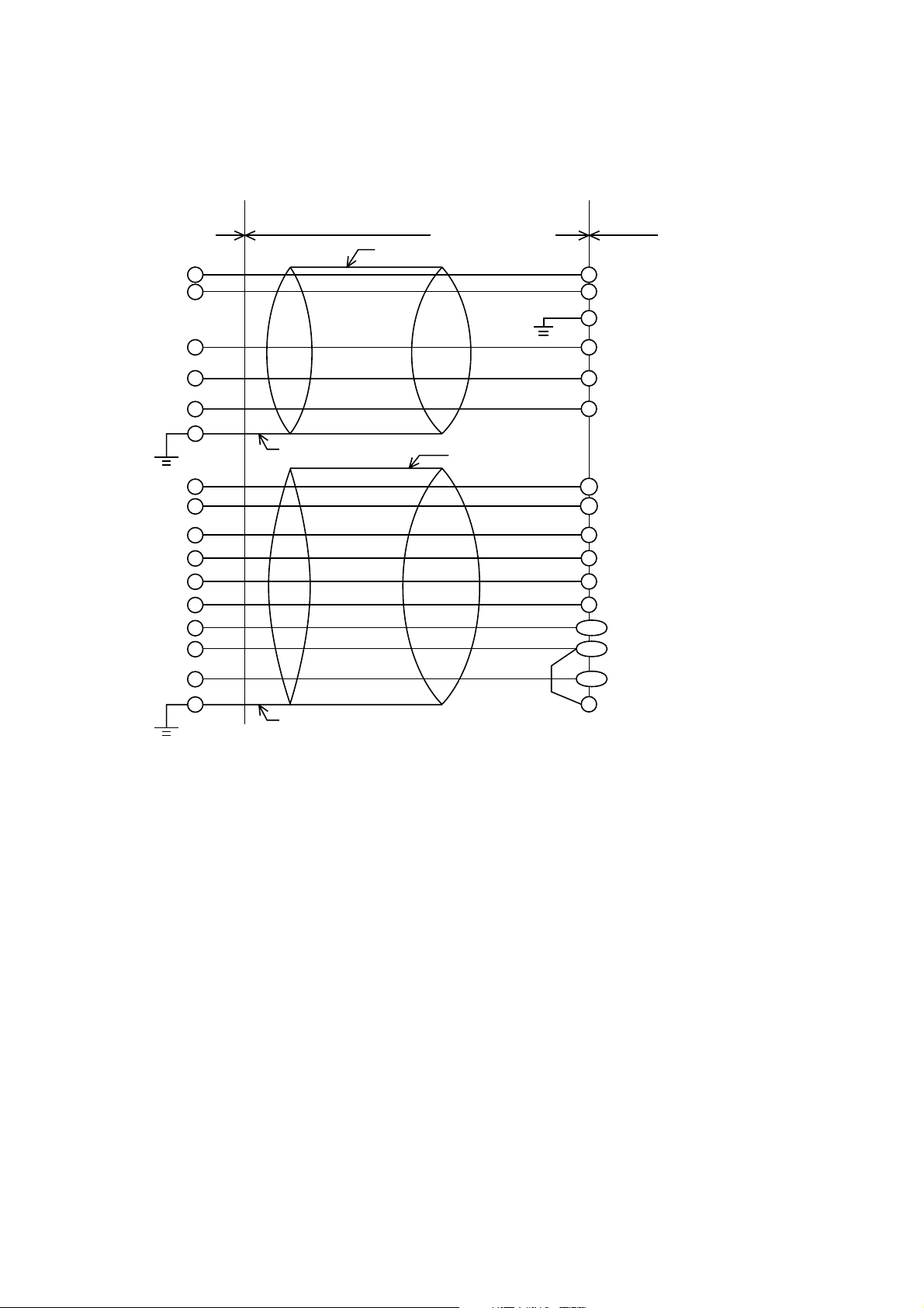
3-4. Wiring Procedure
1) Recommended wiring for pulse width input
Instrument
room
Shield Note 1
CVV - S
External wiring
CVV - S
+
-
E
U
D
C
I +
I -
H
C
L
C
P/D
P/D
ˇ´
ˇ
Pulse-to-pneumatic
pressure converter
+24V
} power supply
0V
E
Up signal
Down signal
COM
Feedback signal
+
}
(4 to 20 mA DC or
–
20 to 4 mA DC)
High limit
Common
Low limit
Common
Supply power down
}
monitor signal
*Jumper
S/D
C
Supply pneumatic pressure down
}
signal
Shield Note 1
Note 1: Ground the cable shield only on the instrument room side (Class 3 or higher).
Note 2: Install the jumpers on the external wiring.
Note 3: Although a large number of additional functions can be selected on the pulse-to-
pneumatic pressure converter, the number of external wires may be limited depending
on the conduit dimensions. The cable shapes and the number of wire cores should be
your guides when selecting functions.
Note 4: Ground the main unit to Class 3 or higher.
Figure 3-4-1 Wiring Procedure (for pulse width input)
3 - 3
Page 11

2) Recommended wiring for pulse train input
Use KPEV-S for up and down signals and CVV-S for other signals.
Instrument
room
Shield Note 1
KREV-S
External wiring
CVV-S
+
+24V
--
0V
E
E
U
Up signal
D
Down signal
C
COM
I+
+
I-
H
C
L
C
P/D
P/D
}
–
High limit
Common
Low limit
Common
Supply power down
}
monitor signal
Pulse-to-pneumatic
pressure converter
} power supply
Feedback signal
(4 to 20 mA DC or
20 to 4 mA DC)
Supply pneumatic pressure down
*Jumper
S/D
C
}
signal
Shield Note 1
Note 1: Ground the cable shield only on the instrument room side (Class 3 or higher).
Note 2: Install the jumpers on the external wiring.
Note 3: Although a large number of additional functions can be selected on the pulse-to-
pneumatic pressure converter, the number of external wires may be limited depending
on the conduit dimensions. The cable shapes and the number of wire cores should be
your guides when selecting functions.
Note 4: Ground the main unit to Class 3 or higher.
Figure 3-4-2 Wiring Procedure (for pulse train input)
3 - 4
Page 12

3) Recommended cables
Up and down signals
Pulse train input cable : KPEV-S.
Pulse width input cable : CVV-S.
Signals other than up and down signals : CVV-S.
1 KPEV-S cable specifications
(Used for up and down signals for pluse train input)
Polyethylene insulated vinyl sheath cable for shielded instrumentation
Performance :
Conductor : twisted soft copper wire for electrical use (JIS C 3102)
Insulator : polyethylene
Pair twisting : two wire cores twisted together at a proper pitch
Structure: 2P 3, blanket shielding
Electrical characteristics
Conductor : Nominal cross area: 2 mm
2
Structure : 7 cores/0.6 mm
Conductor resistance : 9.61 ohms/km
Line capacity (reference value) : 0.08 µF
Sheath thickness : 1.5 mm
External diameter : 15.0 mm
2 CVV-S cable specifications
(Used for signals other than up and down signals for pulse train input)
Vinyl insulated vinyl sheath cable for shielded instrumentation
Performance :
Conductor : twisted soft copper wire for electrical use (JIS C 3102)
Insulator : vinyl
Structure : 6 cores or 8 cores, blanket shielding
Electrical characteristics
Conductor : Nominal cross area : 2 mm
2
Structure : 7 cores/0.6 mm
Outside shape : 1.8 mm
Conductor resistance : 9.42 ohms/km
Line capacity (reference value) : 0.12 µF/km
Sheath thickness : 1.5 mm
External diameter : 14.0 to 15.0 mm
(depends on the number of cores)
3 - 5
Page 13

4) Outside cable diameter and number of wire cores
Structure table CVV-S (2-301.25 mm2)
Structure table CVV-S (2-302 mm2)
Packings applicable to waterproof glands
Use one of three kinds : 12,13, and 15 in diameter.
3 - 6
Page 14

4. Adjustment and Setting
4-1. Preparation
Connect as shown below.
To stabilize, warm up for at least 30 minutes before operation.
Note 1.
Speed
changeover
switch
High speed when on
Power
supply
When testing contact for
conductivity, connect to terminal
indicated by asterisk (*).
Class 3 grounding
Pulse-to-Pneumatic Pressure Converter
Distribution frame with two
pneumatic pressure monitors
Current output (4 to 20 mA)
Ammeter
Power supply for current output
(P/I power externally supplied)
Supplied pneumatic pressure
200 to 990 kPa
Reducing valve
Digital
manometer
Pneumatic pressure output
20 to 100 kPa
Apply load of ø 4, 3m+20cc
Tester
Pulse generator
Note 1 Remove jumper plate when testing withstand voltage
or insulation resistance.
Distribution frame with limit contact output
Figure 4-1 Instrument connection
Tools
1. Digital manometer
2. Ammeter
3. 24VDC power supply
4. Pulse generator for up and down
signals
5. Switch (for changing speed)
6. Air supply: 200 to 990kPa with air set
140kPa without air set
7. Tester for checking contact (output)
4 - 1
Page 15

4-2. Adjustment of Pneumatic Pressure Output (Figure 4-2)
Perform zero and span adjustments of pneumatic output with mechanical stoppers for upper and lower
limits (between the 56T helical gear and base) in contact.
Use the fine-zero adjustment screw and fine-span adjustment nuts on the transmitter.
1) At the lower contact with mechanical stopper
Pneumatic pressure output: 16kPa (-5%F.S.) ±1%F.S.
2) At the upper limit of contact with mechanical stopper
Pneumatic pressure output: 104kPa (105%F.S.) ±1%F.S.
Repeat zero and span adjustments until conditions (1) and (2) are met.
• Turn off power and remove the pulse motor connector, so that coupling can be done easily by hand.
• Pneumatic pressure output is measured by connecting a tube to the pneumatic pressure output check
plug.
Note 1 : Upper and lower limits are set to -3+/-1%F.S. and 103+/-1%F.S. The output value
must not exceed the mechanical stopper range.
Cap for pneumatic pressure output check plug
Terminal block for upper limit
Rough-zero
adjustment screw
(zero rise)
Input spring
Terminal block for
lower limit
Fine-zero
adjustment screw
Set screw for fixing cam, (Note 1.)
2 each for upper and lower limits (M3)
Cam for upper limit
Microswitch for upper limit
Microswitch for lower limit
Pulse motor
Span adjustment nut
Figure 4-2 Mechanical assembly
Pneumatic pressure
transmitter
4 - 2
Cam for lower limit
Page 16

4-2-1. Changing contact of limit contact signal
The following are contacts between the limit contact signal terminal block and customer terminal
connection cables.
Customer terminal cables
HL
........... Upper limit contact cable
HL .C ...... Upper limit common cable
LL............ Lower limit contact cable
LL .C ....... Lower limit common cable
Upper limit contact (terminal block)
• When using at NC (normally closed) (type H or E)
HL → NC (terminal board)
HL .C → C (terminal board)
• When using at NO (normally opened) (type K or F)
HL → NO (terminal block)
HL .C → C (terminal block)
Lower limit contact (terminal block)
• When using at NC (normally closed) (type H or E)
LL → NC (terminal board)
LL .C → C (terminal board)
• When using at NO (normally opened)
LL → NO (terminal board)
LL .C → C (terminal board)
Terminal block for lower limit
Red
Brown
Yellow
Blue
To customer terminal block
Terminal block for upper limit
Mechanical assembly
Figure 4-2-1 Connecting limit contact signal terminal block with customer terminals
4 - 3
Page 17

4-3. Adjustment of Current Output (Figure 4-3)
4-3-1. For direct feature
Conduct wiring and piping as shown in Figure 3-2-1.
1) Adjust input up and down so that pneumatic pressure output is about (*1) 20kPa (0% F.S.), then zeroadjust the P/I converter to attain current output corresponding to pneumatic pressure output (*2).
2) Adjust input up and down so that pneumatic pressure output is about 100kPa (100% F.S.), then spanadjust the P/I converter to attain current output corresponding to pneumatic pressure output.
Repeat steps (1) and (2) until the specified accuracy is achieved.
For reverse characteristics, start from step (3) below.
(*1): Pneumatic pressure output cannot be set precisely since it changes with a pulse motor.
(*2): To calculate the current output corresponding to pneumatic pressure output:
I = 4 + ( ) 16
P – 20
80
I : corresponding current output [mA DC]
P: pneumatic pressure output [kPa]
4-3-2.
For reverse feature
1) Set pneumatic pressure output to about 20kPa (0% F.S.). Zero-adjust so that current output becomes
20mA.
2) Set pneumatic pressure output to about 100kPa (100% F.S.). Span-adjust so that current output
becomes 4mA. (See (2) note (*2) of Section 4-3-1.)
Repeat steps (1) and (2) until the specified accuracy is achieved.
I = 20 – ( ) 16 (For reverse feature)
P – 20
80
4 - 4
Page 18

Zero adjustment
Span adjustment
Current output check terminal
Figure 4-3 P/I conversion unit
4-4. Setting Pneumatic Pressure Monitor
1) For models with both a pneumatic-pressure signal monitor (set at M1 (upper limit): 90±1%F.S., M2
(lower limit): 10±1%F.S.when shipping) and a supplied-air pressure drop monitor (set at 110kPa
when shipping), alarm settings are changed by adjusting the setting wheel on each unit. To raise the
set value, turn the setting wheel counterclockwise.
When only one monitor is used, select the upper limit or lower limit alarm.
2) Connect the monitor unit terminal and customer terminal connection cable as shown below.
(When used as an upper limit alarm) M1 monitor
Monitor terminal block
Orange
Common
(When used as a lower limit alarm) M2 monitor (or when used M1 monitor as a lower limit alarm)
Monitor terminal block
Orange
Common
Purple
Purple
(Purple)
Alarm contact is NC
Alarm contact is NO
(Purple)
Alarm contact is NO
Alarm contact is NC
4 - 5
Page 19

(When used as a supplied pneumatic pressure drop monitor) S/M monitor
Monitor terminal block
Green
Common
Black
(Black)
Alarm contact is NO
Alarm contact is NC
4-5. Setting Output Speed
1) Setting high speed output
Turn on the section between the customer terminal block (SPD COM) and (SPD). Adjust the variable
resistor for high speed on the main printed plate assembly to set the specified speed.
2) Setting low speed output
Turn off the section between customer terminal block (SPD COM) and (SPD). Adjust the variable
resistor for low speed on the main printed plate assembly to set the specified speed.
External terminal block connector
Connector for pulse motor
High-speed control
Figure 4-5 Setting output speed
4 - 6
Low-speed control
Page 20

4-6. Manual Operation (with A/M switch)
A manually-operated unit has a reducing valve for manual pneumatic-pressure setting and auto/manual
switch.
From this unit, switch A → M and M → A following the procedure below.
Under automatic operation (lever set to A), the automatic adjustment output pneumatic pressure is
displayed on the output pneumatic-pressure manometer. Pressing the check button displays output
(manual adjustment output pressure) of the reducing valve. To switch to manual operation, operate the
setting knob of the reducing valve to set the manual output to be the same as the automatic output, then
switch the mode.
Under manual operation (lever set to M), the reducing valve output is displayed on the output pneumaticpressure manometer, and remote operation of the valve is enabled. Pressing the check button displays
automatic adjustment output. To switch to automatic operation, set automatic output to the same as
manual output, then switch the mode.
Setting knob
Automatic output
Manual output
Reducing valve
Switch lever
Auto/Manual switch
Balance check button
Figure 4-6 Manual operation
Output pneumatic
pressure
Manual operation unit circuit
Check button
Output pneumaticpressure manometer
Supplied pneumatic
pressure
4 - 7
Page 21

5. Parts List
KEY NO. Part No. Name Quantity
1 80345502–ITEM Case Assembly 1a 10
2 80345454–001 Door Assembly 1a 7
3 80345503–001 Mechanical part assembly 1a 5
4 80345504–001 Pilot valve installed 1a 5
5 80250366–ITEM Output pneumatic pressure indicator 1a 7
6 80345505–001 S/M pneumatic pressure drop monitor 1a 7
7 80345505–002 Pneumatic pressure signal monitor(M1) 1a 7
8 80345505–003 Pneumatic pressure signal monitor(M2) 1a 7
9 80353282–001 Manual operation mechanism 1a 5
10 80513486–ITEM KF Air set 1a 5
11 80345506–ITEM P/I 1a 7
12 80345437–ITEM Main printed plate assembly 1a 5
13 80345442–ITEM Customer terminals 1a 7
Recommendation
exchange period
(years)
14 80510478–ITEM SUS water-proof gland 1 10
80510497–001 Plastic water-proof gland 1 10
Note 1: "-ITEM" depends on instrument specifications.
5 - 1
Page 22

Fig 5-1. Parts key No.
5 - 2
Page 23

6. Maintenance
6-1. Reguler Maintenance
1) Check the supplied air pressure
Keep the supplied air pressure unit clean. Drain unit and check filters regularly. Check the
compressor, the air cleaning and dehumidifying unit, and the tank.
6-2. Periodical Maintenance and Checking
1) Check for air leaks
Make sure that there is no air leak from the air pipe or the connection joints.
2) Check the nozzle flapper for staining
Remove stains on the nozzle flapper of the pneumatic pressure sending unit (mechanical parts
assembly, see Figure 4-2, with a cloth impregnated with a solvent such as petroleum, naphtha
or chlorosene 1, 1, 1-Trichloroethane (Chloroethene). Wipe gently to prevent damage to the
flapper beam (plate spring).
3) Check the gear mechanism of the pulse motor for wear
Damaged or worn gears, especially the worm gears and worm wheels must be replaced.
4) Check the pilot relay (Figure 6-1)
(1) Remove the pilot relay from the manifold : remove the two screws (14), the spring
washers (15), and the gaskets.
(2) Disassemble the pilot relay : remove the two flat-head screws (13).
(3) Dismount parts (6) to (12). Parts (2) to (5) need not be dismounted unless they need
replacing.
(4) Clean the metal parts with a solvent such as petroleum, naphtha or chlorosene. 1, 1, 1-
Trichloroethane (Chloroethene).
Do not stain the diaphragms with the solvent.
Clean the valve stem (2) on the seal surface and the hole. Let solvent be absorbed by
pressing the conic spring (4) to push the valve stem (2) in the compression direction.
(5) Check the inside of the exhaust ring (10) for stains. If stained, clean with a cloth
impregnated with a solvent.
(6) Dry all the parts with clean compressed air.
(7) Replace the rubber diaphragms (8) and (11) if they are worn or damaged.
(8) Reassemble the pilot relay : replace all parts in correct order and tighten them with two
flat-head screws (13).
(9) Remount the pilot relay on the manifold, position the gasket (1) correctly.
(10) Fix the pilot relay on the manifold using mounting screws (14) and two spring washers
(15).
6 - 1
Page 24

5) You are recommended to replace rubber parts (such as the diaphragms and gaskets on the pilot
relay, the tube for piping, and the O-ring for the check plug of the pneumatic pressure sending
unit) at intervals of about five years, though this may vary depending on conditions.
Figure 6-1 Pilot relay disassembled
6 - 2
Page 25

Page 26

Terms and Conditions
We would like to express our appreciation for your purchase and use of Azbil Corporation's products.
You are required to acknowledge and agree upon the following terms and conditions for your purchase of Azbil Corporation's
products (system products, field instruments, control valves, and control products), unless otherwise stated in any separate
document, including, without limitation, estimation sheets, written agreements, catalogs, specifications and instruction manuals.
1. Warranty period and warranty scope
1.1 Warranty period
1.2 Warranty scope
Azbil Corporation's products shall be warranted for one (1) year from the date of your purchase of the said products or
the delivery of the said products to a place designated by you.
In the event that Azbil Corporation's product has any failure attributable to azbil during the aforementioned warranty
period, Azbil Corporation shall, without charge, deliver a replacement for the said product to the place where you
purchased, or repair the said product and deliver it to the aforementioned place.
Notwithstanding the foregoing, any failure falling under one of the following shall not be covered under this warranty:
(1) Failure caused by your improper use of azbil product
(noncompliance with conditions, environment of use, precautions, etc. set forth in catalogs, specifications,
instruction manuals, etc.);
(2) Failure caused for other reasons than Azbil Corporation's product;
(3) Failure caused by any modification or repair made by any person other than Azbil Corporation or Azbil
Corporation's subcontractors;
(4) Failure caused by your use of Azbil Corporation's product in a manner not conforming to the intended usage of
that product;
(5) Failure that the state-of-the-art at the time of Azbil Corporation's shipment did not allow Azbil Corporation to
predict; or
(6) Failure that arose from any reason not attributable to Azbil Corporation, including, without limitation, acts of God,
disasters, and actions taken by a third party.
Please note that the term “warranty” as used herein refers to equipment-only-warranty, and Azbil Corporation shall not
be liable for any damages, including direct, indirect, special, incidental or consequential damages in connection with or
arising out of Azbil Corporation's products.
2. Ascertainment of suitability
3. Precautions and restrictions on application
You are required to ascertain the suitability of Azbil Corporation's product in case of your use of the same with your
machinery, equipment, etc. (hereinafter referred to as “Equipment”) on your own responsibility, taking the following
matters into consideration:
(1) Regulations and standards or laws that your Equipment is to comply with.
(2) Examples of application described in any documents provided by Azbil Corporation are for your reference
purpose only, and you are required to check the functions and safety of your Equipment prior to your use.
(3) Measures to be taken to secure the required level of the reliability and safety of your Equipment in your use
Although azbil is constantly making efforts to improve the quality and reliability of Azbil Corporation's
products, there exists a possibility that parts and machinery may break down.
You are required to provide your Equipment with safety design such as fool-proof design, *1 and fail-safe
design*2 (anti-flame propagation design, etc.), whereby preventing any occurrence of physical injuries, fires,
significant damage, and so forth. Furthermore, fault avoidance, *3 fault tolerance,*4 or the like should be
incorporated so that the said Equipment can satisfy the level of reliability and safety required for your use.
*1. A design that is safe even if the user makes an error.
*2. A design that is safe even if the device fails.
*3. Avoidance of device failure by using highly reliable components, etc.
*4. The use of redundancy.
Azbil Corporation's products other than those explicitly specified as applicable (e.g. azbil Limit Switch For Nuclear Energy)
shall not be used in a nuclear energy controlled area (radiation controlled area).
Any Azbil Corporation's products shall not be used for/with medical equipment.
The products are for industrial use. Do not allow general consumers to install or use any Azbil Corporation's product.
However, azbil products can be incorporated into products used by general consumers. If you intend to use a product for
that purpose, please contact one of our sales representatives.
In addition,
you are required to conduct a consultation with our sales representative and understand detail specifications, cautions
for operation, and so forth by reference to catalogs, specifications, instruction manual, etc. in case that you intend to use
azbil product for any purposes specified in (1) through (6) below.
Moreover, you are required to provide your Equipment with fool-proof design, fail-safe design, anti-flame propagation
design, fault avoidance, fault tolerance, and other kinds of protection/safety circuit design on your own responsibility to
ensure reliability and safety, whereby preventing problems caused by failure or nonconformity.
(1) For use under such conditions or in such environments as not stated in technical documents, including catalogs,
specification, and instruction manuals
(2) For use of specific purposes, such as:
* Nuclear energy/radiation related facilities
[For use outside nuclear energy controlled areas] [For use of Azbil Corporation's Limit Switch For Nuclear
Energy]
* Machinery or equipment for space/sea bottom
* Transportation equipment
[Railway, aircraft, vessels, vehicle equipment, etc.]
* Antidisaster/crime-prevention equipment
Page 27

* Burning appliances
* Electrothermal equipment
* Amusement facilities
* Facilities/applications associated directly with billing
(3) Supply systems such as electricity/gas/water supply systems, large-scale communication systems, and traffic/air
traffic control systems requiring high reliability
(4) Facilities that are to comply with regulations of governmental/public agencies or specific industries
(5) Machinery or equipment that may affect human lives, human bodies or properties
(6) Other machinery or equipment equivalent to those set forth in items (1) to (5) above which require high reliability
and safety
4. Precautions against long-term use
Use of Azbil Corporation's products, including switches, which contain electronic components, over a prolonged period
may degrade insulation or increase contact-resistance and may result in heat generation or any other similar problem
causing such product or switch to develop safety hazards such as smoking, ignition, and electrification.
Although acceleration of the above situation varies depending on the conditions or environment of use of the products,
you are required not to use any Azbil Corporation's products for a period exceeding ten (10) years unless otherwise
stated in specifications or instruction manuals.
5. Recommendation for renewal
Mechanical components, such as relays and switches, used for Azbil Corporation's products will reach the end of their life
due to wear by repetitious open/close operations.
In addition, electronic components such as electrolytic capacitors will reach the end of their life due to aged deterioration
based on the conditions or environment in which such electronic components are used.
Although acceleration of the above situation varies depending on the conditions or environment of use, the number of
open/close operations of relays, etc. as prescribed in specifications or instruction manuals, or depending on the design
margin of your machine or equipment, you are required to renew any Azbil Corporation's products every 5 to 10 years
unless otherwise specified in specifications or instruction manuals.
System products, field instru ments (sensors such as pressure/flow/level sensors, regulating valves, etc.) will reach the end
of their life due to aged deterioration of parts.
For those parts that will reach the end of their life due to aged deterioration, recommended replacement cycles are
prescribed. You are required to replace parts based on such recommended replacement cycles.
6. Other precautions
Prior to your use of Azbil Corporation's products, you are required to understand and comply with specifications (e.g.,
conditions and environment of use), precautions, warnings/cautions/notices as set forth in the technical documents
prepared for individual Azbil Corporation's products, such as catalogs, specifications, and instruction manuals to ensure
the quality, reliability, and safety of those products.
7. Changes to specifications
Please note that the descriptions contained in any documents provided by azbil are subject to change without notice for
improvement or for any other reason.
For inquires or information on specifications as you may need to check, please contact our branch offices or sales offices,
or your local sales agents.
8. Discontinuance of the supply of products/parts
Please note that the production of any Azbil Corporation's product may be discontinued without notice.
For repairable products, we will, in principle, undertake repairs for five (5) years after the discontinuance of those
products. In some cases, however, we cannot undertake such repairs for reasons, such as the absence of repair parts.
For system products, field instruments, we may not be able to undertake parts replacement for similar reasons.
9. Scope of services
Prices of Azbil Corporation's products do not include any charges for services such as engineer dispatch service.
Accordingly, a separate fee will be charged in any of the following cases:
(1) Installation, adjustment, guidance, and attendance at a test run
(2) Maintenance, inspection, adjustment, and repair
(3) Technical guidance and technical education
(4) Special test or special inspection of a product under the conditions specified by you
Please note that we cannot provide any services as set forth above in a nuclear energy controlled area (radiation
controlled area) or at a place where the level of exposure to radiation is equivalent to that in a nuclear energy controlled
area.
AAS-511A-014-04
Page 28

Page 29

Page 30

Page 31

Document Number : CM2-APN100-2001
Document Name : Multifunction Pulse-to-Pneumatic
Pressure Converter Model J-APN11
Date : 1st edition: Mar. 1997
3rd editoin: Mar. 2015
Issued / Edited by : Azbil Corporation
Page 32

 Loading...