

Page 1
Control Valve
Model HLS_ _ _/HTS_ _ _/HPS_ _ _/HLC_ _ _/HSC_ _ _/HAV_ _ _
User's Manual
OM2-8113-0201
Page 2

NOTICE
While this information is presented in good faith and believed to
be accurate,Azbil Corporation disclaims the implied warranties of
merchantability andfitness for a particular purpose and makes no
express warranties except asmay be stated in its written agreement with
and for its customer.
In no event is Azbil Corporation liable to anyone for any indirect,
special orconsequential damages. e information and specications in
this documentare subject to change without notice.
© 2012 - 2018 Azbil Corporation All Rights Reserved.
Page 3

Table of Contents
Chapter 1. General . . . . . . . . . . . . . . . . . . . . . . . . . . . . . . . . . . . . . . . . . . . . . . . . . . . . . . . . . . . . . .1-1
1-1. Scope 1-1
1-2. Major components of control valves . . . . . . . . . . . . . . . . . . . . . . . . . . . . . . . . . . . . . . . . . . . . . . . . . . . 1-1
1-3. Structures . . . . . . . . . . . . . . . . . . . . . . . . . . . . . . . . . . . . . . . . . . . . . . . . . . . . . . . . . . . . . . . . . . . . . . . . . . . . 1-1
1-4. Nameplate . . . . . . . . . . . . . . . . . . . . . . . . . . . . . . . . . . . . . . . . . . . . . . . . . . . . . . . . . . . . . . . . . . . . . . . . . . . 1-3
Chapter 2. Installation . . . . . . . . . . . . . . . . . . . . . . . . . . . . . . . . . . . . . . . . . . . . . . . . . . . . . . . . . .2-1
2-1. Maximum lifting loads of eyebolts . . . . . . . . . . . . . . . . . . . . . . . . . . . . . . . . . . . . . . . . . . . . . . . . . . . . . 2-1
2-1. Installing valve in process pipe . . . . . . . . . . . . . . . . . . . . . . . . . . . . . . . . . . . . . . . . . . . . . . . . . . . . . . . . 2-1
2-1. Item to be checked after installation and before starting operation . . . . . . . . . . . . . . . . . . . . . 2-2
Chapter 3. Inspection and Maintenance . . . . . . . . . . . . . . . . . . . . . . . . . . . . . . . . . . . . . . . . .3-1
Chapter 4. Disassembly and Assembly . . . . . . . . . . . . . . . . . . . . . . . . . . . . . . . . . . . . . . . . . . .4-1
4-1. Detaching actuator from valve body . . . . . . . . . . . . . . . . . . . . . . . . . . . . . . . . . . . . . . . . . . . . . . . . . . . 4-1
4-2. Disassembly and assembly of valve body . . . . . . . . . . . . . . . . . . . . . . . . . . . . . . . . . . . . . . . . . . . . . . 4-1
4-3. Disassembly and assembly of actuator . . . . . . . . . . . . . . . . . . . . . . . . . . . . . . . . . . . . . . . . . . . . . . . . 4-11
4-4. Disassembly and assembly of model PSA 1 . . . . . . . . . . . . . . . . . . . . . . . . . . . . . . . . . . . . . . . . . . . 4-13
4-5. Disassembly and assembly of model HA2, HA3, or HA4 actuator . . . . . . . . . . . . . . . . . . . . . . . 4-19
4-6. Disassembly and assembly of model PSA6 actuator . . . . . . . . . . . . . . . . . . . . . . . . . . . . . . . . . . .4-25
4-7. Disassembly and assembly actuator . . . . . . . . . . . . . . . . . . . . . . . . . . . . . . . . . . . . . . . . . . . . . . . . . . 4-28
Chapter 5. Adjustment . . . . . . . . . . . . . . . . . . . . . . . . . . . . . . . . . . . . . . . . . . . . . . . . . . . . . . . . . .5-1
Chapter 6. Direct/Reverse Action Type Conversion and Spring Range Change of Actuator 6-1
6-1. Direct/Reverse action change . . . . . . . . . . . . . . . . . . . . . . . . . . . . . . . . . . . . . . . . . . . . . . . . . . . . . . . . . 6-1
6-2. Stroke and range spring change . . . . . . . . . . . . . . . . . . . . . . . . . . . . . . . . . . . . . . . . . . . . . . . . . . . . . . . 6-5
Chapter 7. Instructions for Top Handwheel of Actuator . . . . . . . . . . . . . . . . . . . . . . . . . . .7-1
7-1. Model PSA1 actuator . . . . . . . . . . . . . . . . . . . . . . . . . . . . . . . . . . . . . . . . . . . . . . . . . . . . . . . . . . . . . . . . . . 7-1
7-1-1. Operating instructions . . . . . . . . . . . . . . . . . . . . . . . . . . . . . . . . . . . . . . . . . . . . . . . . . . . . . . . . . 7-1
7-1-2. Disassembly and Assembly of Top Handwheel . . . . . . . . . . . . . . . . . . . . . . . . . . . . . . . . . . 7-3
7-2. Model HA2, HA3, or HA4 actuator . . . . . . . . . . . . . . . . . . . . . . . . . . . . . . . . . . . . . . . . . . . . . . . . . . . . . 7-5
7-2-1. Operating instructions . . . . . . . . . . . . . . . . . . . . . . . . . . . . . . . . . . . . . . . . . . . . . . . . . . . . . . . . . 7-5
7-2-2. Disassembly and assembly of top handwheel . . . . . . . . . . . . . . . . . . . . . . . . . . . . . . . . . . . 7-5
Chapter 8.
Instructions for Side Handwheel of Actuator . . . . . . . . . . . . . . . . . . . . . . . . . . . . . . . . 8-1
8-1. Installation procedure . . . . . . . . . . . . . . . . . . . . . . . . . . . . . . . . . . . . . . . . . . . . . . . . . . . . . . . . . . . . . . . . 8-1
8-2. Operating instructions . . . . . . . . . . . . . . . . . . . . . . . . . . . . . . . . . . . . . . . . . . . . . . . . . . . . . . . . . . . . . . . . 8-1
8-3. Disassembly of side assembly of side handwheel . . . . . . . . . . . . . . . . . . . . . . . . . . . . . . . . . . . . . . 8-2
i
Page 4

Chapter 9. Instructlons for Bellows Sealed Type of Control Valves . . . . . . . . . . . . . . . .9-1
9-1. Model HLS control valves . . . . . . . . . . . . . . . . . . . . . . . . . . . . . . . . . . . . . . . . . . . . . . . . . . . . . . . . . . . . . 9-1
9-1-1. Structures . . . . . . . . . . . . . . . . . . . . . . . . . . . . . . . . . . . . . . . . . . . . . . . . . . . . . . . . . . . . . . . . . . . . . . 9-1
9-1-2. Disassembly and assembly . . . . . . . . . . . . . . . . . . . . . . . . . . . . . . . . . . . . . . . . . . . . . . . . . . . . . 9-3
9-2. Model HTS control valves . . . . . . . . . . . . . . . . . . . . . . . . . . . . . . . . . . . . . . . . . . . . . . . . . . . . . . . . . . . . . 9-4
9-2-1. Structures . . . . . . . . . . . . . . . . . . . . . . . . . . . . . . . . . . . . . . . . . . . . . . . . . . . . . . . . . . . . . . . . . . . . . . 9-4
9-2-2. Disassembly and assembly . . . . . . . . . . . . . . . . . . . . . . . . . . . . . . . . . . . . . . . . . . . . . . . . . . . . . 9-5
Chapter 10. Azbil Low Emission standard-compliant gland packing . . . . . . . . . . . . 10-1
10-1. Overview . . . . . . . . . . . . . . . . . . . . . . . . . . . . . . . . . . . . . . . . . . . . . . . . . . . . . . . . . . . . . . . . . . . . . . . . . . . 10-1
10-2. Structure . . . . . . . . . . . . . . . . . . . . . . . . . . . . . . . . . . . . . . . . . . . . . . . . . . . . . . . . . . . . . . . . . . . . . . . . . . . 10-1
10-3. Installation into the gland . . . . . . . . . . . . . . . . . . . . . . . . . . . . . . . . . . . . . . . . . . . . . . . . . . . . . . . . . . 10-2
10-3-1. Preparation for installation . . . . . . . . . . . . . . . . . . . . . . . . . . . . . . . . . . . . . . . . . . . . . . . . . . .10-2
10-3-2. Start of installation . . . . . . . . . . . . . . . . . . . . . . . . . . . . . . . . . . . . . . . . . . . . . . . . . . . . . . . . . . .10-3
10-3-3. Retightening . . . . . . . . . . . . . . . . . . . . . . . . . . . . . . . . . . . . . . . . . . . . . . . . . . . . . . . . . . . . . . . . 10-6
10-4. Parts List . . . . . . . . . . . . . . . . . . . . . . . . . . . . . . . . . . . . . . . . . . . . . . . . . . . . . . . . . . . . . . . . . . . . . . . . . . .10-6
Chapter 11. Certified ISO 15848-1 compliant low emission gland packing . . . . . . 11-1
11-1. Overview . . . . . . . . . . . . . . . . . . . . . . . . . . . . . . . . . . . . . . . . . . . . . . . . . . . . . . . . . . . . . . . . . . . . . . . . . . . 11-1
11-2. Structure . . . . . . . . . . . . . . . . . . . . . . . . . . . . . . . . . . . . . . . . . . . . . . . . . . . . . . . . . . . . . . . . . . . . . . . . . . . 11-2
11-3. Starting Operation . . . . . . . . . . . . . . . . . . . . . . . . . . . . . . . . . . . . . . . . . . . . . . . . . . . . . . . . . . . . . . . . . 11-2
11-4. Assembling the parts of the gland . . . . . . . . . . . . . . . . . . . . . . . . . . . . . . . . . . . . . . . . . . . . . . . . . . 11-3
11-4-1. Preparation for assembly . . . . . . . . . . . . . . . . . . . . . . . . . . . . . . . . . . . . . . . . . . . . . . . . . . . . .11-3
11-4-2. Assembly . . . . . . . . . . . . . . . . . . . . . . . . . . . . . . . . . . . . . . . . . . . . . . . . . . . . . . . . . . . . . . . . . . . . 11-5
11-5. Parts List . . . . . . . . . . . . . . . . . . . . . . . . . . . . . . . . . . . . . . . . . . . . . . . . . . . . . . . . . . . . . . . . . . . . . . . . . . .11-9
11-6. Application to existing control valves . . . . . . . . . . . . . . . . . . . . . . . . . . . . . . . . . . . . . . . . . . . . . .11-13
11-7. Disposal . . . . . . . . . . . . . . . . . . . . . . . . . . . . . . . . . . . . . . . . . . . . . . . . . . . . . . . . . . . . . . . . . . . . . . . . . . .11-13
Chapter 12. Troubleshooting . . . . . . . . . . . . . . . . . . . . . . . . . . . . . . . . . . . . . . . . . . . . . . . . . . 12-1
Chapter 13. Recommended Spare Parts . . . . . . . . . . . . . . . . . . . . . . . . . . . . . . . . . . . . . . . 13-1
ii
Page 5

Chapter 1. General
1-1. Scope
This manual covers the instructions for the following Control Valves.
Model HLS : Small-port single-seated control valves
Model HLC : Small-port cage guide type single-single seated control valves
Model HTS : Top-guide single-seated control valve
Model HSC : Cage type single-seated control valve
Model HPS : Top-guide high-pressure single-seated control valves
Model HAV : Venturi throat type angle control valves.
For the valve positioners, refer the following operators manuals.
Model VPE OM2-8310-0410 Pneumatic valve positioner for small actuators
Model HTP OM2-83 10-0200 Pneumatic valve positioner (Single Acting type)
Model HEP 15, l6, l7 OM2-8313-0100 Electro-Pneumatic Valve Positioner (Single Acting
Model AVP 300/301/302/200/201/202 CM2-AVP300-2001 Electro-pneumatic positioner
Model AVP 303/203 CM2-AVP303-2001 Electro-pneumatic positioner
Model AVP 701/702 CM2-AVP702-2001 Smart valve positioner 700 series (HART)
Model AVP 703 CM2-AVP703-2001 Smart valve positioner 700 series
Type)
(F
OUNDATION
fieldbus)
1-2. Major components of control valves
Each control valve is comprised of two major components, namely, a valve body and an
actuator. Various combinations of valve body and actuator are available to meet various type
of uses with different valve sizes, pressure ratings, types of connections, types of materials, and
actuator sizes.
(For details of specifications, refer to Specification Sheets SS2-8113-0200, -0210, .0300, -0310,
-0400, and -2600.)
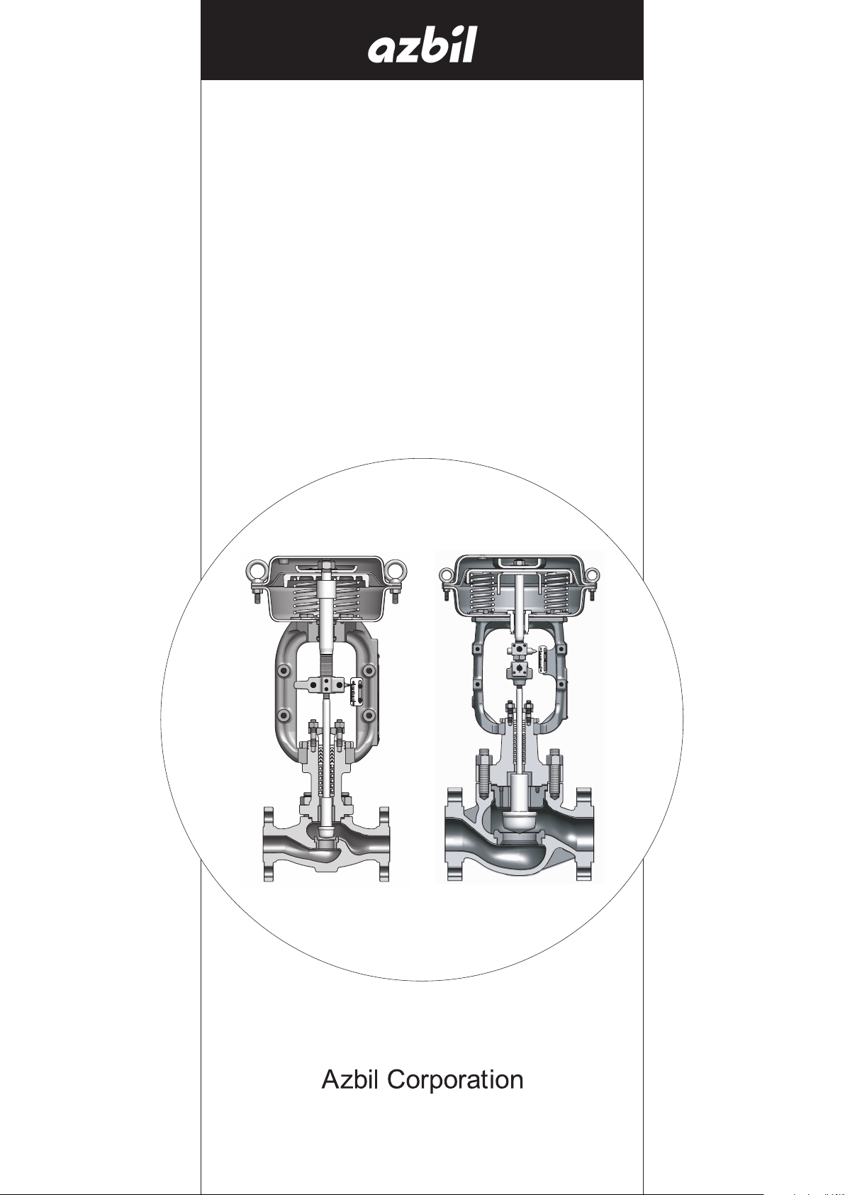
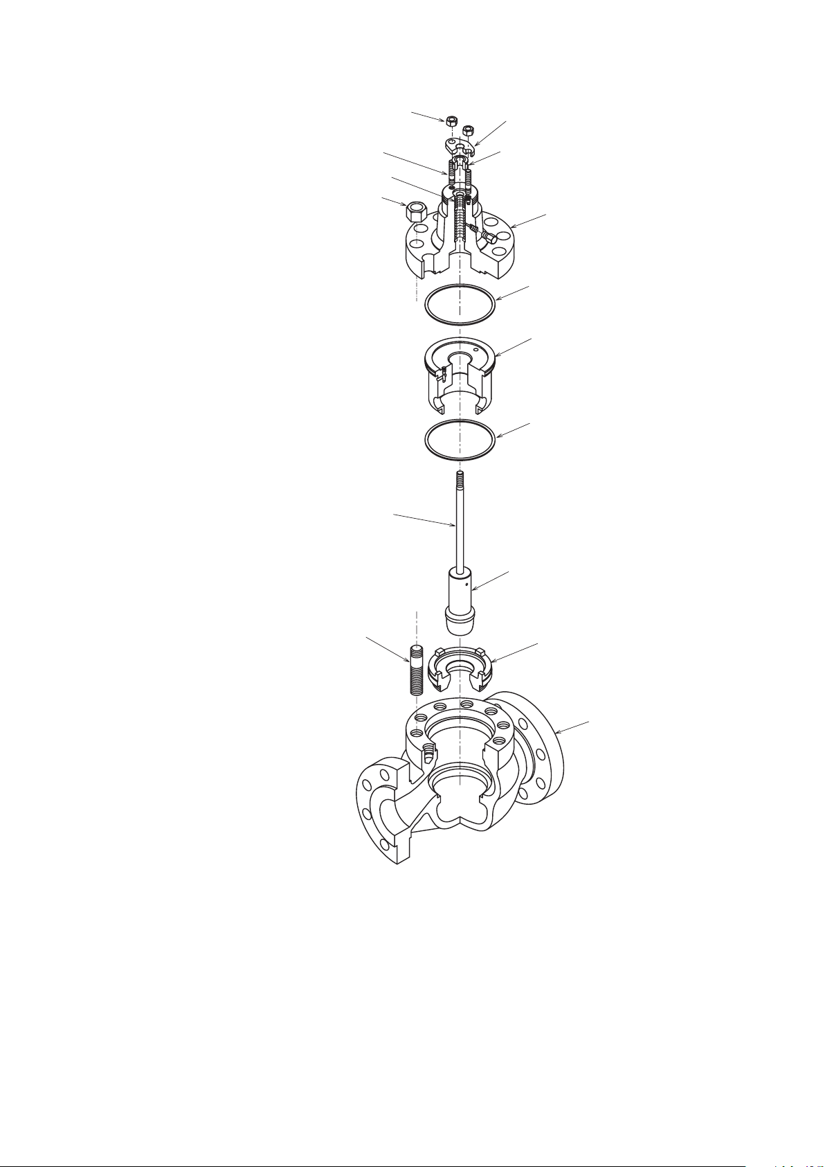
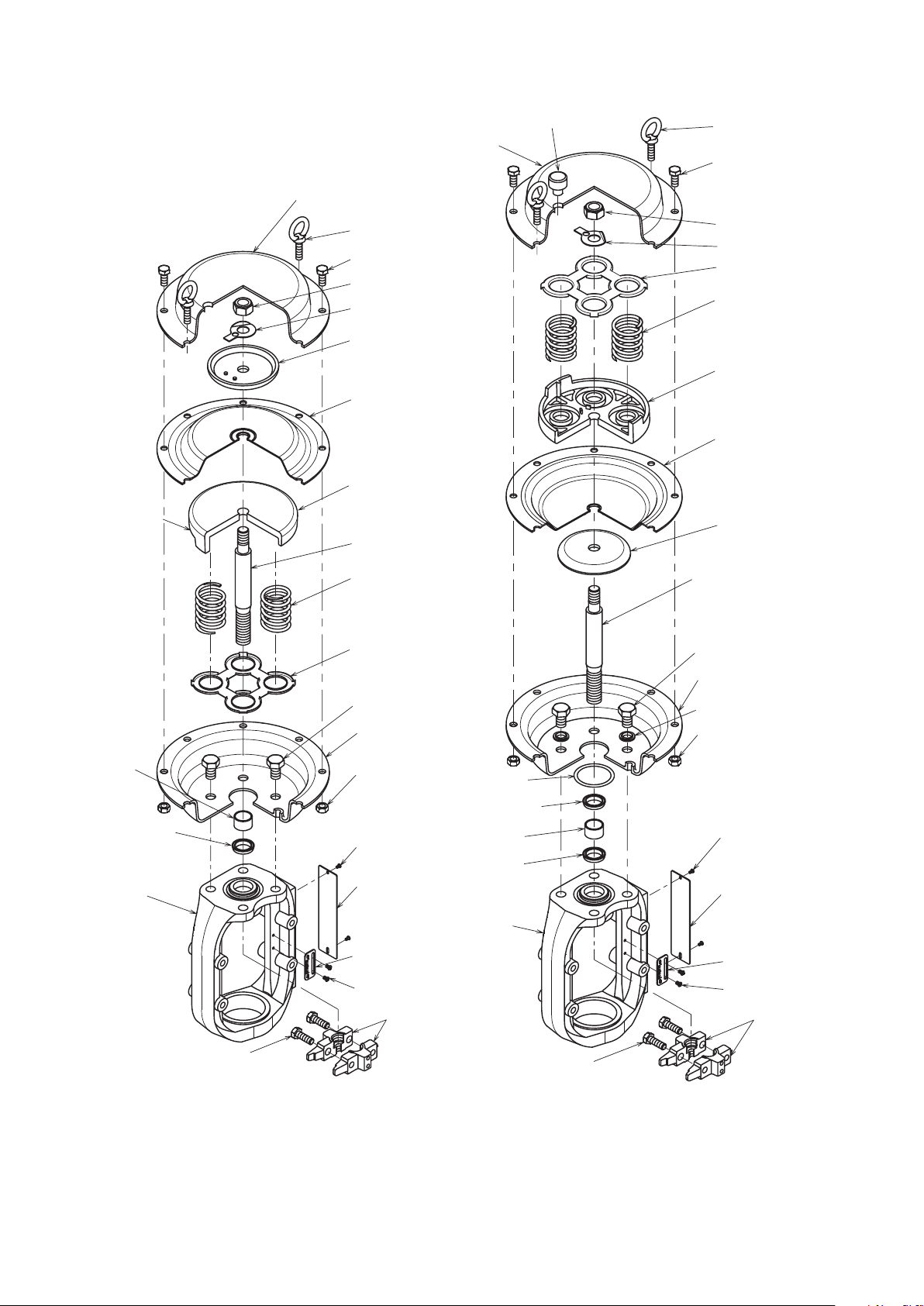
1-3. Structures
The structures of typical control valves are shown is Figure 1-1 through Figure 1-3.
The valve body is connected to the bonnet with stud bolts and nuts. A gasket is (two gaskets
are) provided at the connection Chapter to seal against the internal fluid or to let the valve
body make up a pressure vessel. The valve plug is supported by the guide ring and cage, and
driven by the actuator. The actuator has multiple springs and a diaphragm, and converts the
pneumatic control signal into a mechanical (positional) control signal with which to position
the valve plug.
1-1
Page 6
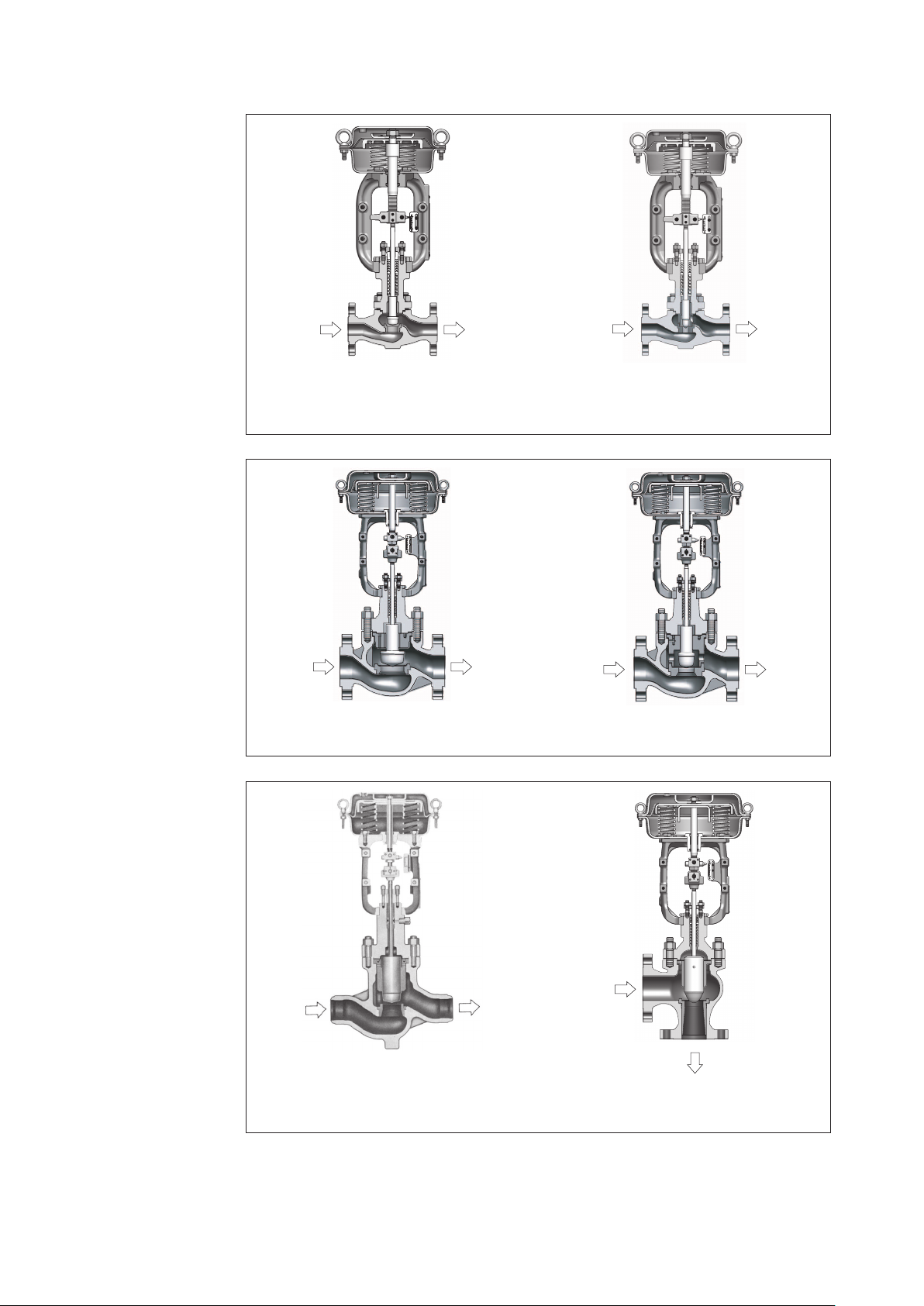
Figure 1-1A Small-Port Single Seated
Control Valve, Model HLS
(Direct Action Type)
Figure 1-1B Model HLC
Figure 1-2A Top-Guided Single Seated
Control Valve, Model HTS
Figure 1-3A Top-Guided High-Pressure
Single Seated Control Valve, Model HPS
Figure 1-2B Model HSC
Figure 1-3B Venturi-Throat-Type Angle
Control Valve, Model HAV
1-2
Page 7
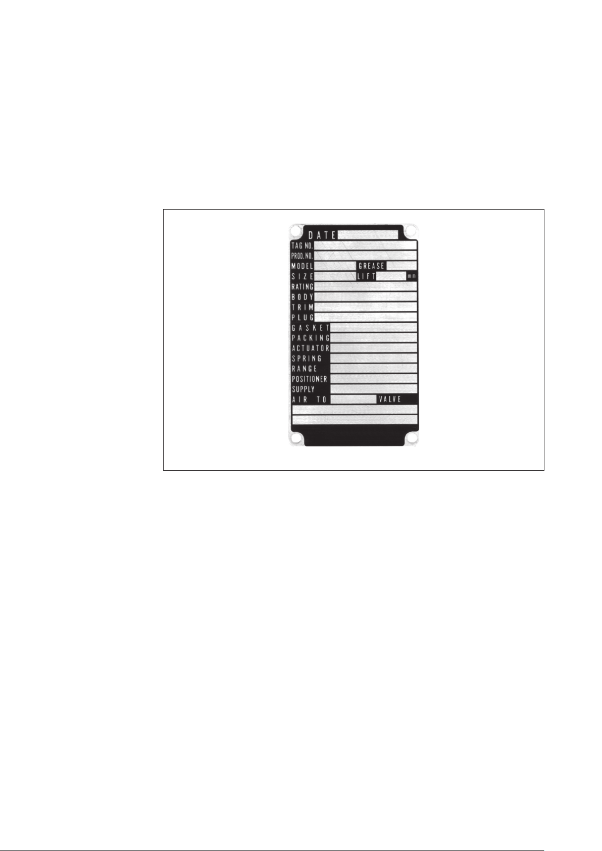
1-4. Nameplate
A nameplate as shown in Figure 1-4 is posted on each control valve. The nameplate indicates
the model number, valve size, pressure rating, trim material, date of manu.facture and other
major specifications of the control valve. Before installing the con.trol valve, make sure
that the specifications indicated on the nameplate conform with the conditions of use. The
nameplate indicate also the product number (PROD.NO.) of the control valve. Please mention
this number also when consulting an Azbil Corp. agent for replacement of parts or other
modification of the control valve.
Figure 1-4 Nameplate
1-3
Page 8

1-4
Page 9

Chapter 2. Installation
2-1. Maximum lifting loads of eyebolts
The diaphragm case has a pair of lifting eyebolts. These eyebolts primarily are for lifting the
actuator alone. When using the eyebolts for other purposes (such as lifting an actuator bed
to its valve body or other components), note that the allowable maxi.mum lifting loads of the
eyebolts are as shown in the following table.
Table 2-1. Maximum lifting loads of eyebolts
Actuator Model No. Allowable Maximum Lifting
PSA1
HA2
HA3
HA4
Note: The eyebolts may be used to lift the actuator together with its valve buy (cast globe
valve) of up to pressure rating “Class 600”. When doing this, be extremely careful so that
no shock or other abnormal force is applied to the actuator or the valve body.
2-1. Installing valve in process pipe
(1) Before installing the valve in the process pipe, remove foreign matter (such as scales and
welding chips) from both upstream and downstream sides of the pro.cess pipe.
(2) Confirm that the direction of process fluid flow conforms with that of the arrow.head
mark provided on the valve body.
(3) Pay attention so that the pipe connection gaskets do not extrude into the process pipe
inside. Be sure to use gaskets made of material which is suitable for the pro.cess fluid. The
welding type of valve employ no gaskets.
(4) Pay attention so that no excessively large stress is conveyed from the process pipe to
the valve body. Uniformly tighten the bolts of the process pipe connection flange. The
high pressure type of valves have no flanges, since they are connected to the process by
welding.
(5) Before connecting the air pipes to the actuator and positioner, blow the pipes to clean
them.
(6) Do not install any heating or cooling provisions on the bonnet.
Load of Eyebolts
160 kg
160 kg
160 kg
220 kg
Weight of Actuator Alone
8 kg
16 kg
32 kg
68 kg
2-1
Page 10

2-1. Item to be checked after installation and before starting operation
(1) Check that there is no leak from air piping.
(2) Check that the bolts and nuts of the diaphragm case are not loose. Standard tight.ening
torques are as follows:
(3) Tighten the packing flange nuts to prevent leak from the gland packing chapter. Standard
tightening torques are as shown in Table 2-2.
Table 2-2. Tightening Torques of Packing Flange Nuts
Unit: N•m{kgf/cm
2
}
Valve Stem
Diameter
(mm)
10
V PTFE
packing
PTFE Yarn
Packing
(P4519)
Expanded graphite Packing V PTFE + PTFE
P6610CH + P6528
P6610CH + M8590
T2200 + P6710CH (Type2)
Yarn Packing
PTFE + V7233
PTFE + TK2006
9 {90} 5 {50} 3 {30}
13 15 {150} 8 {80} 5 {50}
16 24 {240} 13 {130} 8 {80}
1 {8}
20 32 {320} 18 {180} 10 {100}
25 - - 28 {280} 15 {150}
30 66 {660} 36 {360} 20 {200}
Note: The tightening torques mentioned in the above are only to give you reference values.
Note that tightening torques may vary depending on the type of packing.
Table 2-3. Tightening Torques of packing Flange Nuts for PTFE yarn (Certified ISO
15848-1-compliant low-emission gland packing)
Model Actuator model Stem size Tightening torque
HLS,HLC
HTS,HSC
HA2
HA3
HA3
HA4
PSA6,DAP560
DAP1000(X)
10 mm 12 N·m
φ
13 mm 20 N·m
φ
16 mm 33 N·m
φ
20 mm 44 N·m
φ
30 mm 54 N·m
φ
40 mm 65 N·m
φ
Table 2-4. Tightening Torques of packing Flange Nuts for expanded graphite (Certified ISO
15848-1-compliant low-emission gland packing)
Model Actuator model Stem size Tightening torque
HLS,HLC
HTS,HSC
HA2
HA3
HA3
HA4
PSA6,DAP560
DAP1000(X)
10 mm 12 → 0 (loosening) → 8 N·m
φ
13 mm 20 → 0 (loosening) → 13 N·m
φ
16 mm 33 → 0 (loosening) → 22 N·m
φ
20 mm 44 → 0 (loosening) → 30 N·m
φ
30 mm 54 → 0 (loosening) → 36 N·m
φ
40 mm 85 → 0 (loosening) → 43 N·m
φ
2-2
Page 11
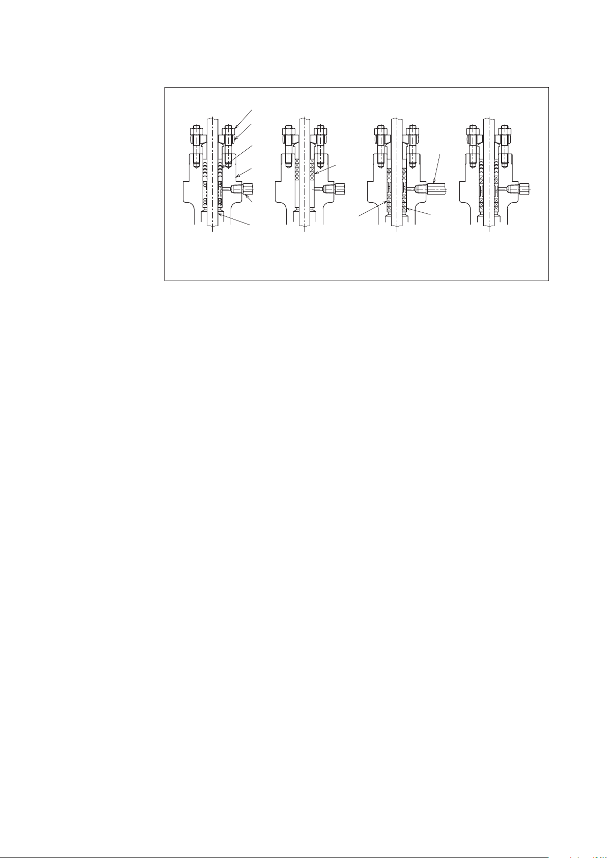
Nut
Packing
Packing
Packing
Flange
V PTFE Packing
V PTFE
Packing
Bonnet
Blind
Plug
Stem
PTFE Yarn Packing Graphite + Expanded graphite
PTFE Yarn
Packing
Graphite
Packing
Lubricator
Graphite
Yarn
Packing
V PTFE + PTFE Yarn
Figure 2-1 Gland Section
(4) If the valve is provided with a lubricator as shown in Figure 2-2, check whether the
bonnet section has been lubricated or not. To do this, loosen the lubricator handwheel
and turn the squeeze screw. If the squeeze screw turn lightly, and grease in the lubricating
procedure mentioned below. (If the squeeze screw turns heavily, this means that grease
has been applied.)
2-3
Page 12
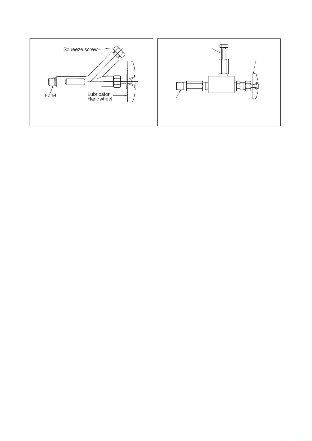
Squeeze
Handwheel
G1/2
Screw
Lubricator
Figure 2-2 Lubricator (Class 600 or under)
Lubricating procedure
(a) prepare grease of the type indicated on the nameplate.
(b) Tightly close the lubricator handwheel.
(c) Remove the squeeze screw, apply grease, and set the squeeze screw.
(d) Loosen the lubricator handwheel and drive grease by turning the squeeze screw.
(e) Repeat the procedure of 0), (c) and (d) until turning of the squeeze screw becomes
heavier. Tightly close lubricator handwheel.
(5) Pressurizing valve, check that there is no leak from the gasket sections for connection
to the valve body and process pipe. If leak is found, tighten the nuts. (Especially when
the process f luid temperature is 400 or higher, tighten the nuts again after raising
temperature of the valve in order that it may serve for a longer period without requiring
immediate maintenance service.) Standard tightening torques are shown in Table 4-4,
Table 4-5 of Chapter 4.
(6) When raising temperature of a valve which is used for high temperature service, raise
temperature gradually (standard rate is 100 per hour) and do not operate the valve when
its temperature is being raised.
Figure 2-3 Lubricator for High Pressure Valve
(Class 600 or higher)
2-4
Page 13

Chapter 3. Inspection and Maintenance
Inspect and service the actuator as follows:
(1) Tightening the gland:
Tighten the gland once in every 6 months or thereabout. The tightening procedure is as
given in Section 2-3-(3).
(2) Lubricating the gland:
Lubricating the gland once in every 6 months or thereabout. The lubricating procedure is
as given in Section 2-3-(4).
(3) Check for hunting of valve Position:
Refer to ''Troubleshooting.''
(4) Check for abnormal noise and vibration:
Refer to ''Troubleshooting.''
3-1
Page 14

3-2
Page 15

Chapter 4. Disassembly and Assembly
This Chapter covers the disassembly and assembly procedures of the actuator for its overhaul
or modification.
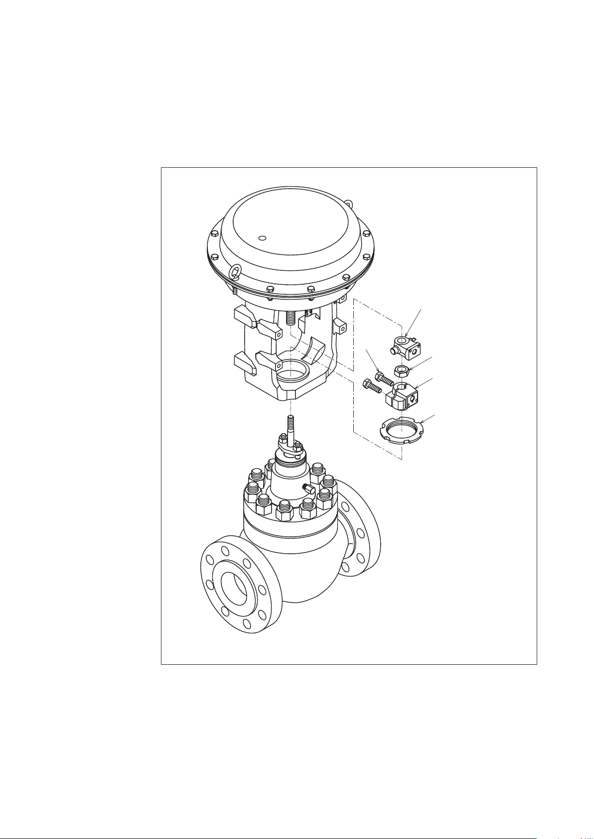
4-1. Detaching actuator from valve body
See Figure 4-7.
(1) Apply to the actuator an air pressure so that the valve position pointer is at a point of 10%
- 20% above the fully closed point.
(2) Loosen the clamping-bolts of the stem connector, remove the stem connector, and detach
the actuator stem from the valve stem.
(3) Remove the clamping-nut of the yoke.
(4) Raise the actuator to detach it from the valve body.
Precautions: For detaching the actuator from the valve body which is kept installed in the
process pipe, be sure to shut down the process for and release the process
pressure before detaching the actuator.
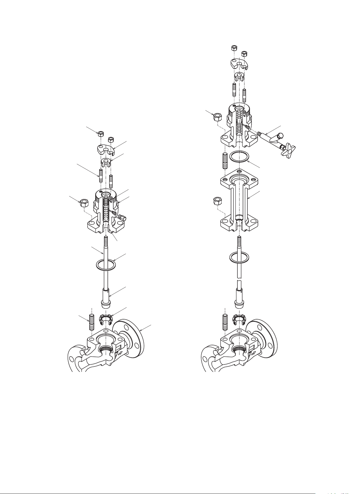
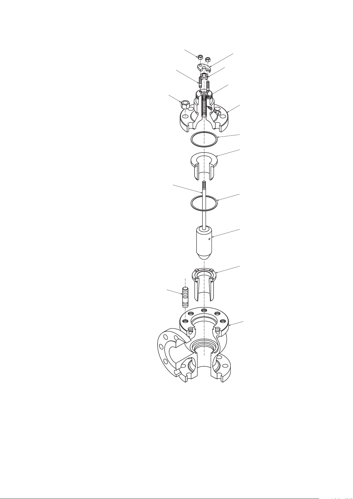
4-2. Disassembly and assembly of valve body
To disassemble or assemble the valve body, refer to Figure 4-1 through Figure 4-6 and proceed
as described below.
(For handling of the bellows sealed type (optional type) of valves, see .)
Disassembly procedure
(1) Loosen the hex nuts of the packing flange.
(2) Remove the hex nuts (1) of the bonnet (extension bonnet).
(3) Raise and detach the bonnet from the valve body.
Precautions: If the valve plug comes out together with the bonnet, remove the plug from the
bonnet by rotating the plug. When doing this, exercise care not to damage the
valve stem.
(4) Model HTS, HPS and HAV Valve
For Model HTS and HPS valve, remove the guide ring. The seat ring is fixed to the valve
body by threading. To remove the seat ring, special tools (optional) are nec.essary.
(Model HLS, HLC valves have no guide ring and in its stead the valve has a guide hushing
pressed in the bonnet.)
Inspection
Inspect the disassembled parts for damage. If any damage is found, replace the parts.
(When ordering parts, mention also the Prod. No. of the valve which is indicated on the
nameplate.)
(1) Do not re-use the removed gland packing. Use fresh packing when assembling the valve.
(2) Check that the seating surfaces of plug and seat ring are not damaged.
4-1
Page 16

(3) Check that the gasket-contacting surfaces of valve body, bonnet and guide ring are not
damaged. Do not re-use the removed gasket. Use fresh gasket when assem.bling the valve.
(4) Check that the plug guide section, the stem, and the internal guiding sections of guide
bushing are not damaged..
Assembly procedure
• Model HLS, HLC
(1) Securely fix the seat ring onto the valve body with threads, using the special tools
(optional). For the tightening torque, see Table 4-1
(2) Set the plug on the seat ring. (Apply lubricant ''Neverseize" to the threaded sec.tions,
except those of the oil-inhibited valves.)
(3) Put the bonnet on the valve body and check that the bonnet is correctly mated with the
indented section of the valve body: Tighten the nuts uniformly, paying atten.tion so that
they are not tightened unevenly (tighten- alternately the ones located at symmetrical
positions). For the tightening torque, see Table 4-3.
(4) Insert the gland packing as shown in Figure 2-1.
Note: When yarn packing sheets are used, overlap sheets in such manner that their cut
ends are positioned alternately.
(5) Place the packing follower and packing Range, and tighten the nuts. For the tight.ening
torques, see Table 2-2
• Models HTS, HSC, HPS and HAV
(1) Securely fix the seat ring onto the valve body with threads, using the special tools
(optional). For the tightening torque, see Table 4-1 or Table 4-2.
(2) Set the plug on the seat ring. (Refer to the Disassembly Procedures.)
(3) Put a sheet of gasket on the valve body side and place the guide ring in a manner of
covering the plug. (Apply lubricant "Neverseize" to the gaskets, except those of the oilinhibited valves.)
(4) Put the gasket on the guide ring. (Apply lubricant "Neverseize" to the gaskets, except those
of the oil-inhibited valves.)
(5) Put the bonnet on the valve body and check that the bonnet is correctly mated with the
indented section of the valve body. Tighten the nuts uniformly, paying atten.tion so that
they are not tightened unevenly (tighten alternately the ones located at symmetrically
positions). For the tightening torque, see Table 4-3.
(6) Insert the gland packing as shown in Figure 2-1.
Note: When yarn packing sheets are used, overlap sheets in such manner that their cut
ends are positioned alternately.
(7) Place the packing follower and packing flange, and tighten the nuts. For the tight.ening
torques, see Table 2-2.
4-2
Page 17

Table 4-1. Model HLS, HTS, HSC, HAV seated ring tightening torques
Size (in.) Torque (N·m{kgf-cm})
1-1/2 260 {2,600}
2 390 {3,900}
2-1/2 520 {5,200}
3 650 {6,500}
4 800 {8,000}
6 1200 {12,000}
8 1500 {15,000}
1, 3/4 180 {18,000}
Table 4-2. Model HPS seated ring tightening torques
Size (in.) ANSI Class Torque (N·m{kgf-cm})
1 900-2,500 250 {2,500}
1-1/2 900-2,500 310 {3,100}
2 900-2,500 570 {5,700}
3 900-1,500 1,100 {11,000}
3 2, 500 700 {7,000}
Table 4-3. Tightening torques of bonnet stud bolts
Bolt Torque (N·m{kgf-cm})
M12 60 {600}
M16 100 {1,000}
M20 150 {1,500}
M22 200 {2,000}
M24 250 {2,500}
M27 350 {3,500}
M30 500 {5,000}
M33 660 {6,600}
4-3
Page 18

Table 4-4. Bonnet-body bolt size
Models Size (in.) Rating
ANSI, JPI 150# JIS 10K ANSI, JPI 300#,600#
JIS16K, 20K, 30K, 40K
HLS 1/2 to 3 M12*4 M12*4
1-1/2 M16*6 M16*8
2 M16*6 M16*10
2-1/2 M16*6 M20*8
HTS, HCB
3 M20*8 M22*10
4 M20*8 M22*12
6 M22*12 M30*3*12
8 M24*12 M33*3*12
4-4
Page 19
H
Hex Nut (2)
Packing Flange Nut
Stud Bolt
ex Nut (1)
Packing
Valve Stem
Packing Flange
Packing Follower
Gland Packing
Bonnet
Guide Bushing
Gasket (1)
Valve Plug
Lubricator
Gasket (2)
Extension
Bonnet
Stud Bolt
Seat Ring
Valve Body
Figure 4-1-1 Normal Temperature Type Figure 4-1-2 High Temperature Type
(Extended Bonnet Type)
Figure 4-1 Model HLS Control Valves
4-5
Page 20
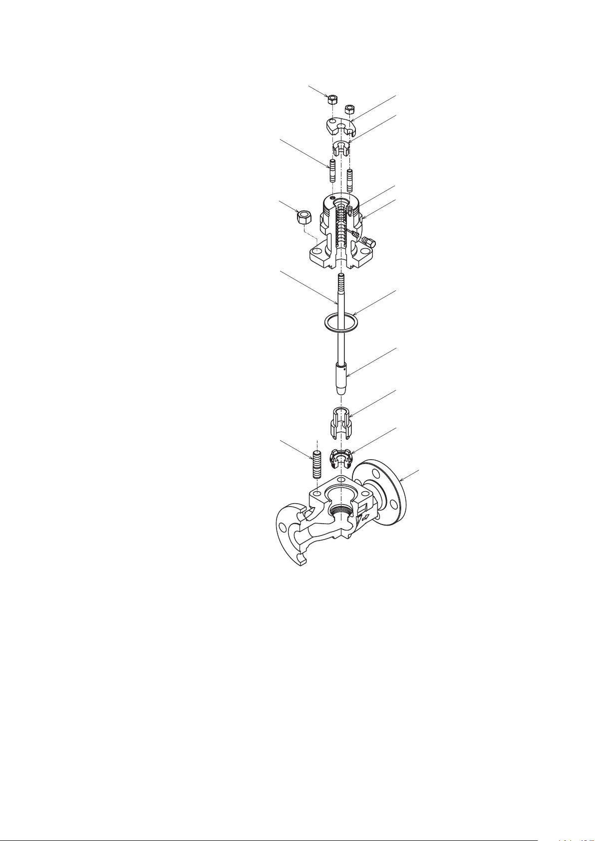
Packing Flange Nut
H
V
e Body
Stud Bolt
ex Nut (1)
a lve Stem
Packing Flange
Packing Follower
Gland Packing
Bonnet
Gasket (1)
Valve Plug
Guide Bushing
Seat Ring
Stud Bolt
Valv
Figure 4-2 Model HLC Control Valves
4-6
Page 21
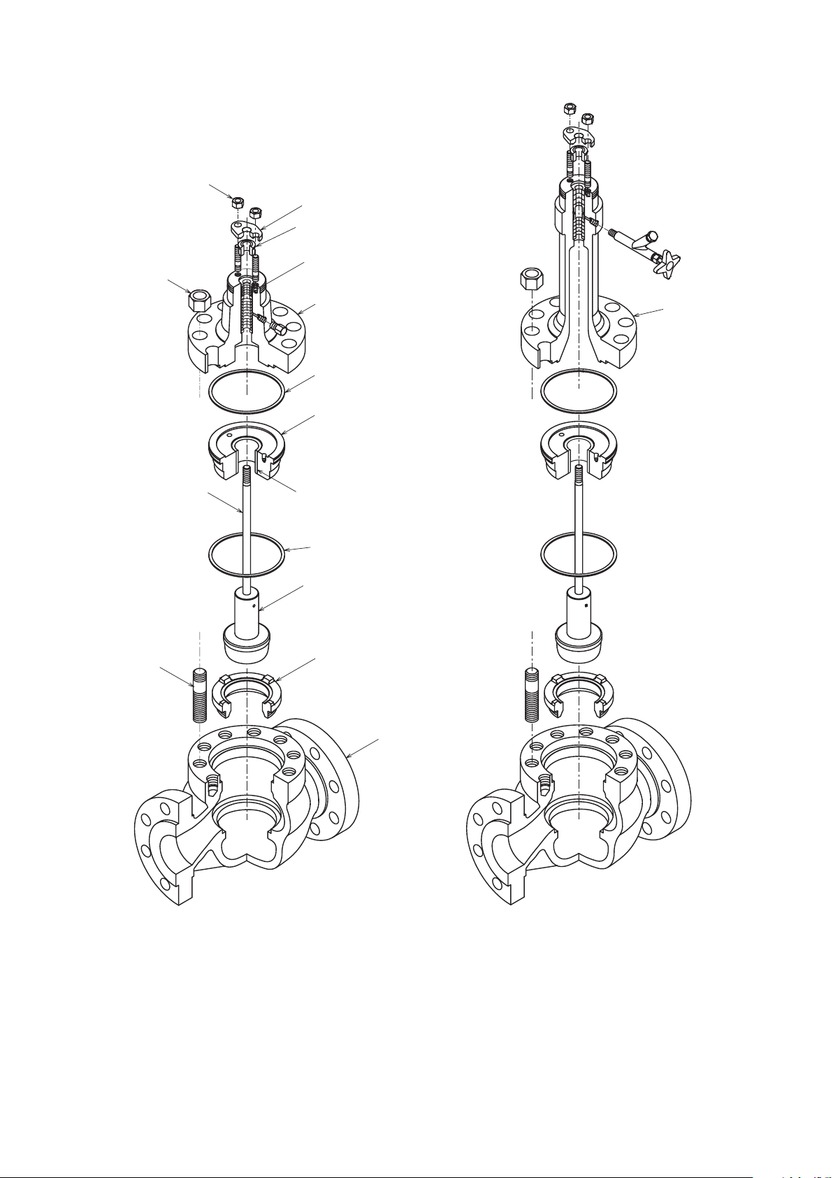
Packing Flange Nut
Stud Bolt
Extension
Packing Flange
Packing Follower
Hex Nut (1)
Valve Stem
Gland Packing
Bonnet
Gasket (1)
Guide Ring
Guide Bushing
Gasket (2)
Valve Plug
Seat Ring
Bonnet
Valve Body
Figure 4-3-1 Normal temperature type Figure 4-3-2 High temperature type
(Extended bonnet type)
Figure 4-3 Model HTS Control Valves
4-7
Page 22
Packing Flange
Packing Flange Nut
e Body
Stud Bolt
Gland Packing
Hex Nut (1)
Valve Stem
Packing Follower
Bonnet
Gasket (1)
Guide Ring
Gasket (2)
Stud Bolt
Valve Plug
Seat Ring
Valv
Figure 4-4 Model HSC Control Valves
4-8
Page 23
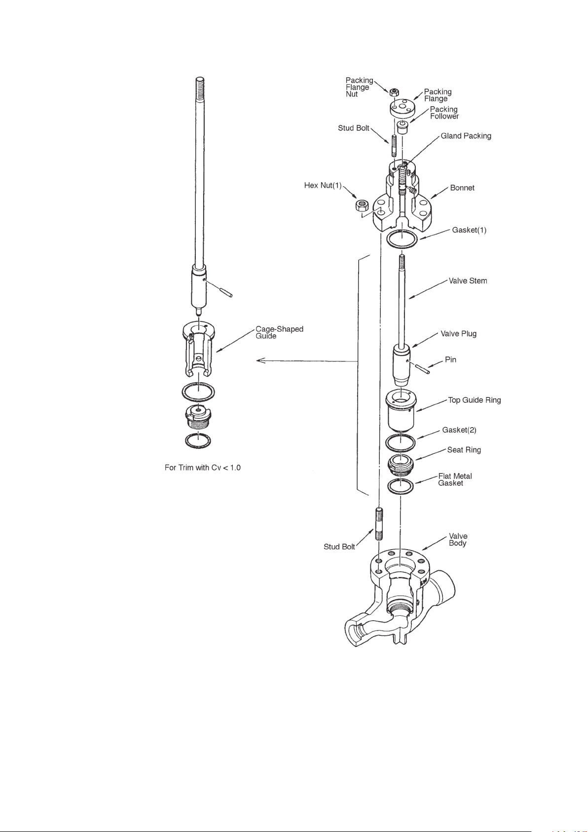
Figure 4-5 Model HPS Control Valves
4-9
Page 24
Paking Flange Nut
Packing Flange
H
e Body
Stud Bolt
ex Nut (1)
Valve Stem
Packing Follower
Gland Packing
Bonnet
Gasket (1)
Guide Ring
Gasket (2)
Valve Plug
Seat Ring
Stud Bolt
Valv
Figure 4-6 Model HAV Control Valves
4-10
Page 25
4-3. Disassembly and assembly of actuator
e Clamping Nut
Normally the actuator requires no adjustment. However, it should be disassembled and
assembled when installing it on a valve body, when modifying its specifications, or when
replacing damaged parts. The disassembly and assembly procedure of the actuator for such
purposes are covered in Sections 4-4 and 4-5. To disassemble the actuator, refer to Figure 4-7
to Figure 4-21.
Pointer
Hex Bolt
Lock Nut
Stem Connector
Yok
Figure 4-7
When disassembling or assembling the actuator, keep it in the vertical attitude. For the
tightening torques of bolts and nuts, see Table 4-4, Table 4-5.
For the names of the parts, see Figure 4-13 and Figure 4-21.
4-11
Page 26

Notes for Disassembly
(1) The nuts for the eyebolts are made of stainless steel. Discriminate these nuts from other
nuts when assembling the diaphragm case.
(2) It is recommendable to make locating marks on the top and bottom diaphragm cases
before disassembly. This will help you to find easily the air piping connector location.
(3) Store the removed parts in a clean place.
CAUTION
Never loosen or remove carelessly the bolts and nuts of the actuator. The actuator
employs powerful compressed springs and if you remove the bolts and nuts carelessly,
the springs may leap out causing hazards. When removing the bolts and nuts, be sure
to observe the instructions given for disassembly and assembly procedures of the
actuator and top handwheel.
4-12
Page 27

4-4. Disassembly and assembly of model PSA 1
Disassembly procedure
A. Direct action model (see Figure 4-8)
(1) Disconnect the air piping and detach the accessories from the actuator.
(2) Remove the stem connector.
(3) Remove the clamping bolts (except the pair of eyebolts) from the diaphragm case.
(4) Alternatively and evenly loosen the pair of eyebolts. The initial setting of the springs is
achieved using these eyebolts.
(5) Removing the diaphragm case. Pull the actuator rod upward and out together with the
diaphragm.
(6) Take out the springs.
B. Reverse action model (see Figure 4-9)
(1) Disconnect the air piping and detach the accessories from the actuator
(2) Remove the stem connector.
(3) Remove the clamping bolts (except the pair of eyebolts) from the diaphragm case.
(4) Alternately and evenly loosen the pair of eyebolts. The initial setting of the springs is
achieved using the eyebolts.
(5) Remove the diaphragm case. Take on the springs.
(6) Pull the actuator rod upward and out together with the diaphragm.
4-13
Page 28
Diaphragm Case (Top)
Bushing
Rain Cap
Connector
Diaphragm
Case (Top)
Eye Bolt
Hex Bolt
Stopper
Part
Eye Bolt
Hex Bolt
Hex Nut
Was her
Diaphragm
Retainer
Diaphragm
Diaphragm
Plate
Spring Plate
Hex Bolt
Rod
Spring
Diaphragm
Case (Bottom)
Hex Nut
Was her
Spring Plate
Spring
Diaphragm
Plate
Diaphragm
Diaphragm
Retainer
Rod
Hex Bolt
Diaphragm
Case (Bottom)
Seal Washer
Hex Nut
Dust Seal
Yoke
Hex Nut
Drive Screw
Name Plate
Scale Plate
Truss Screw
Stem
Connector
Hex Bolt
O-ring
Rod Packing
Bushing
Dust Seal
Yoke
Hex Bolt
Figure 4-8 Direct Action model PSA1D Figure 4-9 Reverse Action model PSA1R
Drive Screw
Name Plate
Scale Cap Plate
Tr uss Screw
Stem
4-14
Page 29
Assembly
Before assembly, check the parts for scratches, damage, deformation, peeling paint or any
other abnormalities. To assemble the actuator, proceed as follows:
A. Direct action models
• See Figure 4-8.
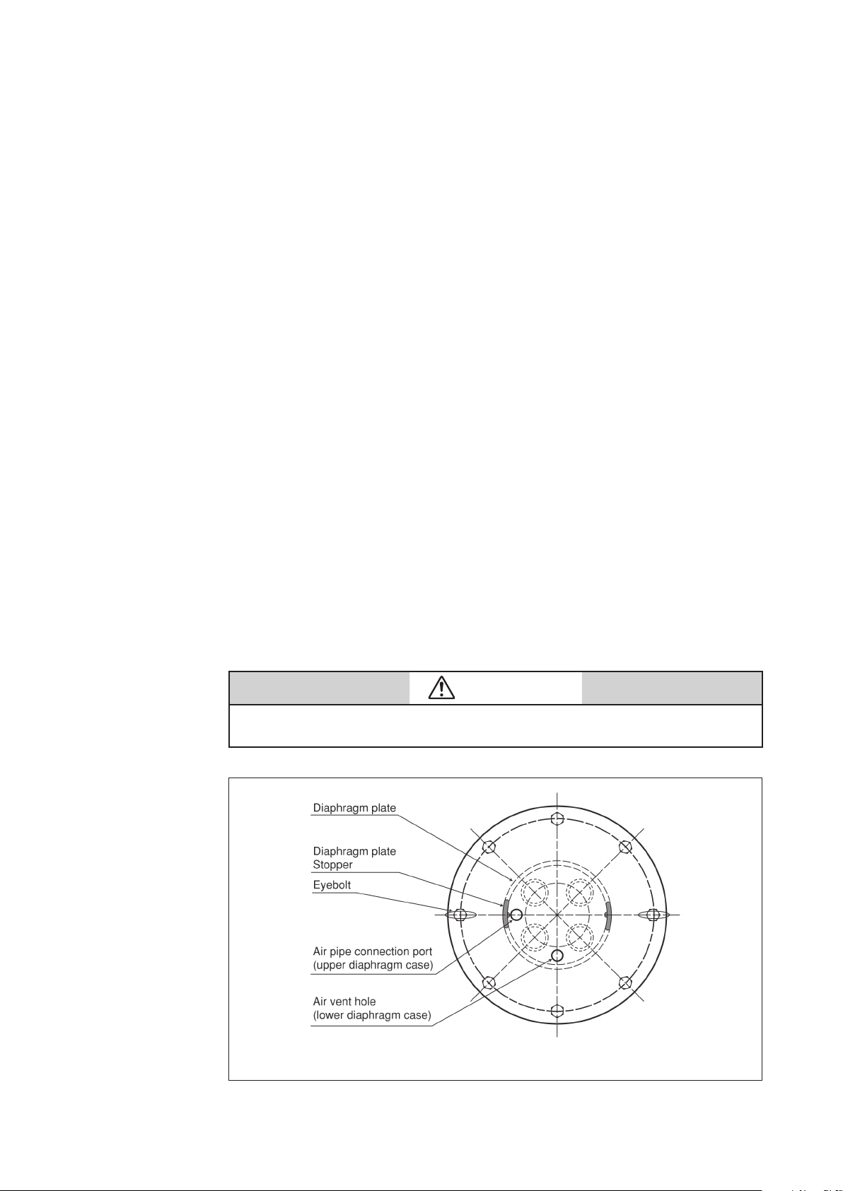
(1) Secure the diaphragm case (bottom) with the four bolts to the yoke. At the same time, set
the air vent hole as in Figure 4-10. For model PSA1D actuator, secure the spring plate to
the diaphragm case and yoke.
(2) Fasten the spring place and install the springs onto the spring plate (see Figure 4-10).
(3) Insert the actuator rod (with diaphragm connected) into the bushing. Be careful to
prevent the bushing's inside surface or dust seal form being damaged by the threaded
section of the rod. If possible, cover the threaded section with adhesive tape.
(4) Rotate the actuator rod, locating the diaphragm plate stopper as shown in Figure 4-10.
(5) Place the top diaphragm case and secure it with the pair of eyebolts.
Note: Set the air pipe connection port to the location shown in Figure 4-10. Tighten
the pair of eyebolts uniformly and alternately. The initial setting of the springs is
completed by tightening these eyebolts.
(6) Clamp the diaphragm case with clamping bolts.
(7) Install the stem connector. Connect the air pipe to its connection port at the top
diaphragm case.
(8) After completing assembly, check the following:
• Apply air pressure of 500 kPa {5 kgf/cm
top diaphragm case, and check the diaphragm periphery for air leakage with soapy
water.
• Check that the actuator operates smoothly through to its full stroke by operating it as an
independent unit.
2
} through the air pipe connection port at the
CAUTION
Install packing for the rod and dustseal in the correct direction. Refer to Figure 4-8.
Figure 4-10 Direct Action Models Model PSA1D Actuator
4-15
Page 30
B. Revers action models
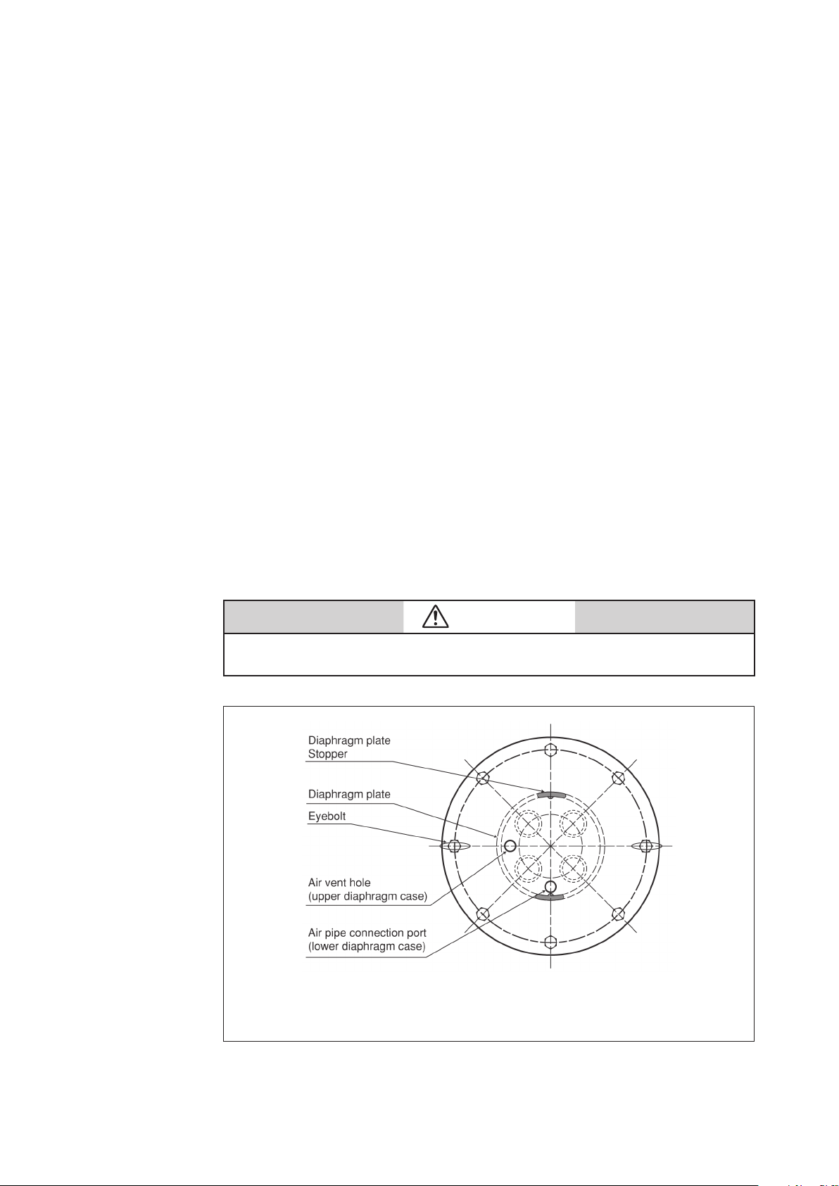
(1) Secure the bottom diaphragm case with the four bolts to the yoke. At the same time, set
the air pipe connection port in the location shown in the Figure 4-11.
(2) Insert the actuator rod (with diaphragm connected) into the bushing. Be careful to
prevent the bushing 's inside surface or dust seal from being damaged by the threaded
section of the rod. If possible, cover the threaded section with adhesive tape.
(3) Rotate the actuator rod, locating its diaphragm plate stopper as shown in Figure 4-11.
(4) Fasten the spring plate and install the springs onto the spring plate. (see Figure 4-11).
(5) Place the top diaphragm case and secure it with the pair of eyebolts.
Note: Set the air vent hole to the location shown in Figure 4-11. Uniformly and alternately
tighten the eyebolts. The initial setting of the springs is completed by tightening
these eyebolts.
(6) Clamp the diaphragm case with clamping bolts.
(7) Install the stem connector.
(8) Install the stem cap onto the air vent port.
(9) Connect the air pipe to its connection port at the bottom diaphragm case.
(10) After completing of assembly, check the following.
• Apply air pressure of 500 kPa {5 kgf/cm
diaphragm case, and check the diaphragm periphery for air leakage with soapy water.
• Check that the actuator operates smoothly through to its full stroke by operating the
actuator as an independent unit.
2
}through the air pie connection port at the
CAUTION
Install packing for the rod and dustseal in the correct direction. Refer to Figure 4-9.
Figure 4-11 Reverse Action Model
Model PSA1R Actuator
4-16
Page 31
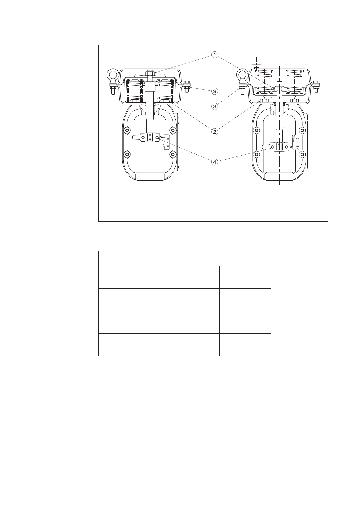
Direct Action Type (Model PSA1D) Reverse Action Type (Model PSA1R)
Figure 4-12 Bolts and Nuts of Actuator
Table 4-5. Tihtening Torques of Bolts and Nuts of Actuator
Unit: (N.m{kgf-cm})
No. Materials
1 SK5 S45C M14
2 S30C M12
3 SUS304 M8
4 SUS304 M8
Note: Install the rain cap on the reverse actuator as follows. Drive the cap into the diaphragm
case until the shoulder (brim) of the cap is brought into contact with the diaphragm
case, then drive the cap further into the diaphragm case by half a turn.
Model
PSA1
45-70
{460-710}
35-50
{360-510}
15-20
{150-200}
10-15
{100-150}
4-17
Page 32

Direct Action Type (Model PSA1D) Reverse Action type (Model PSA1R)
Figure 4-13 Model PSA Actuator
No. Parts Name Material No. Parts Name Material
1 Nut S45C, SUS301 15 Hex Bolt SUS304
2 Diaphragm Case (Top) SAPH400 16 Hex Nut SUS304
3 Diaphragm EPDM, Polyimide 17 Spring Plate SUS304CP
4 Eye Bolt SUS304 18 Hex Bolt S30C
5 Hex Nut SUS304 19 Seal Washer NBR, SPCC
Diaphragm Case (Bottom)
6
7 Bushing SPCC, Bronze, PTFE 21 O-Ring NBR
8 Dust Seal NBR 22 Rod SUS304
9 Yok e A216WBC 23 Truss Screw SUS304, SK5
10 Stem Connector SCS13A 24 Scale Plate SUS304CP
11 Hex Bolt SUS304 25 Drive Screw SUS304
12 Diaphragm Retainer SS400 26 Name Plate SUS304CP
13 Diaphragm Plate AC4A-F 27 Rain Cap SUS304
14 Spring SWOSM-B 28 Washer SUS304CP
SAPH370 20 Rod Packing NBR
4-18
Page 33

4-5. Disassembly and assembly of model HA2, HA3, or HA4 actuator
Disassembly procedure
(a) Direct action type
(1) Disconnect the air piping and detach the accessories from the actuator.
(2) Remove the stem connector, pointer and lock nut. (See Figure 4-21.)
(3) Remove the clamping-bolts (except the pair of eyebolts) of the diaphragm case.
(4) Loosen evenly and alternately the pair of eyebolts. (The initial setting of the springs is
done by these eyebolts.)
(5) Remove the diaphragm case. Pull out upward the actuator rod together with the
diaphragm.
(6) Take out the springs.
Figure 4-14 Actuator model HA2D or
HA3D
4-19
Figure 4-15 Actuator model HA4D
Page 34

(b) Reverse action type
(1) Disconnect the air piping and detach other external items from the actuator.
(2) Remove the stem connector, pointer and lock nut. (See Figure 4-21.)
(3) Remove the clamping-bolts (except the pair of eyebolts) of the diaphragm case.
(4) Loosen evenly and alternately the pair of eyebolts. (The initial setting of the springs is
done by these eyebolts.)
(5) Remove the diaphragm case. Take out the springs.
(6) Pull out upward the actuator rod together with the diaphragm.
Figure 4-16 Actuator model HA2R or
HA3R
4-20
Figure 4-17 Actuator model HA4R
Page 35

Assembly procedure
Before assembly, check the parts for scrapes, damage, deformation, peeling off of paint, and
other abnormality. To assemble the actuator, proceed as followes:
(a) Direct action type
(1) Fix the bottom diaphragm case and yoke with the bolts. (For models HA2D and HA3D,
install the diaphragm case and spring plate together.)
(2) Install the springs on the spring plate. The quantities of springs are as follwes;
Model HA2.....................4 springs
Model HA3, HA4........... 8 springs
Except particular models as follows:
Model HA2, 38 mm stroke,
80 - 240 kPa (0.8 - 2.4 kgf/cm
2
).......Total 8 springs (with double springs)
Model HA3, 50 mm stroke,
80 - 240 kpa (0.8 - 2.4 kgf/cm
2
)....... Total 16 springs (with double springs)
Model HA4, 75 mm stroke,
80 - 240 kPa (0.8 - 2.4 kgf/cm
2
)...... Total l6 springs (with double springs)
(3) Insert the actuator rod (to which the diaphragm is connected) into the bushing, exercising
are not to damage the bushing inside surface or dust seal with the threaded section of the
rod. (For example, cover the threaded section with adhesive tape to prevent damaging the
hushing.) Set the stopper in parallel with the yoke.
(4) Place the top diaphragm case and fix it with the pair of eyebolts.
Notes: • Set the air piping connection port in the location shown in the illustration.
(Figure 4-18)
• Tighten the pair of eyebolts uniformly by tightening them alternately. The
initial setting of the springs is complete by tightening of these eyebolts.
Figure 4-18 Direct Action Type
(5) Clamp the diaphragm case with other clamping-bolts than the pair of eyebolts.
(6) Install the pointer, secure the lock nut, and install the stem connector. (Connect the air
pipe to the air piping connection port of the top diaphragm case.)
(7) After the assembly is complete as above, check the following.
2
1. Applying an air pressure of 490 kPa (5kgf/cm
) via the air piping connection port of
the top diaphragm case, check the diaphragm periphery for air leak by using soapsuds.
2. Check that the actuator smoothly operates for its full stroke.
Note: Check this operation by operating the actuator as an independent unit.
4-21
Page 36

(b) Reverse action type
(1) Fix the bottom diaphragm case and yoke with the bolts.
(2) Insert the actuator rod (to which the diaphragm is connected) into the hushing, exercising
care not to damage the bushing inside surface or dust seal with the thread section of the
rod. (For example, cover the threaded section with adhesive tape to prevent damaging the
bushing.)
(3) Make the stopper (in the diaphragm plate) in parallel with the yoke by turning the rod.
(4) Install the springs on the spring plate. The quantities of springs are as follows:
Model HA2 ..................... 4 springs
Model HA3, HA4 ........... 8 springs
Except particular models as follows:
Model HA2, 38 mm stroke,
80 - 240 kPa (0.8 - 2.4 kgf/cm
2
).......Total 8 springs (with double springs)
Model HA3, 50 mm stroke,
80 - 240 kpa (0.8 - 2.4 kgf/cm
2
)....... Total 16 springs (with double springs)
Model HA4, 75 mm stroke,
80 - 240 kPa (0.8 - 2.4 kgf/cm
2
)...... Total 16 springs (with double springs)
(5) Place the top diaphragm case and fix it with the pair of eyebolts. Set the air vent hole in
the location shown in the illustration (Figure 4-19). Uniformly and alternately tighten the
eyebolts. The initial setting of the springs is complete by tightening of these eyebolts.
Figure 4-19 Reverse Action Type
(6) Clamp the diaphragm case with other clamping-bolts than the pair of eyebolts.
(7) Install the pointer, secure the lock nut, and install the stem connector.
(8) Install the rain cap on the air vent port.
(9) Connect the air pipe to the air piping connection port of the bottom diaphragm case.
(10) After the assembly is complete as above, check the following.
2
1. Applying an air pressure of 490kPa (5kgf/cm
) via the air Piping connection port
of the bottom diaphragm case, check the diaphragm periphery for air leak by using
soapsuds.
2. Check that the actuator smoothly operates for its full stroke.
Note: Check this operation by operating the actuator as an independent unit.
4-22
Page 37

Reverse Action Type
1
5
5
Direct Action Type
4
2
3
6
Figure 4-20 Bolts and Nuts of Actuator
Table 4-6. Tightening Torques of Bolts and Nuts of Actuator
Unit:(N.m{kgf-cm})
No. Materials For Model HA2 For Model HA3 For Model HA4
1 S45C/SUS301 M10 37 {370} M14 100 {1,000} M20 310 {3,170}
2 S30C M12 42 {420} M16 100 {1,000} M24 360 {3,360}
3 S20C M14 69 {690} M18 140 {1,400} M30 710 {7,160}
4
4 S20C M8 16 {160} M8 16 {160} M12 55 {550}
5 SUS304 M8 18 {180} M8 18 {180} M12 63 {630}
6 SUS304 M10 56 {560} M10 56 {560} M12 63 {630}
4-23
Page 38

No. Parts Name Material No. Parts Name Material
Reverse Action Type (Model HA3R)Direct Action Type (Model HA3D)
1 Nut S45C, SUS301 17 Spring SWOSM-B
2 Diaphragm Case (Top) SAPH370 18 Hex Bolt SUS304
3 Diaphragm EPDM+Nylon66 19 Hex Nut SUS304
4 Eye Bolt SUS304 20 Spring Plate SPCC
5 Hex Nut SUS304 21 Hex Bolt S30C
Diaphragm Case (Bottom)
6
SAPH370 22 Seal Washer NBR, SPCC
7 Bushing SPCC, Bronze, PTFE 23 Rod Packing NBR
8 Bearing S25C 24 Rod SUS304
9 Dust Seal NBR 25 Lock Nut SUS304
10 Pointer S25C 26 Truss Screw, Spring
SUS304, SK5
Washer Nut, or Speed
Nut
11 Yo ke SCPH2, A216WBC 27 Scale Plate SUS304CP
12 Stem Connector S25C, S20C 28 Screw SUS304
13 Hex Bolt SUS304, S30C 29 Name Plate SUS304CP
14 Diaphragm Retainer SS400 30 Rain Cap SUS304
15 Stopper SS400 31 Washer SPCC
16 Diaphragm Plate SS400 32 Tapping Screw S20C
Figure 4-21 Cut View of Actuator
4-24
Page 39

4-6. Disassembly and assembly of model PSA6 actuator
Structure
This actuator is comprised of a cylinder, spring unit, lift stopper, spring retainer, hex stay,
yoke, manual handwheel and a single action positioner. For an external view of the a actuator,
refer to "Figure 4-22 Exterior of Model PSA6R".
Figure 4-22 Exterior of Model PSA6R
Assembly on valve body
The Assembling nuts are integral to the valve body connect the yoke and valve body. The stem
connector connects the actuator's rod and valve stem.
Air piping connection
The tubing is connected to the single action positioner when used as a control valve. Refer to
the following instruction manuals for details on the single action positioners.
• Pneumatic positioner (Model HTP) No. OM2-8310-0200
• Electro-pneumatic positioner (Model HEP) No. OM2-8310-0100
• Electro-pneumatic positioner (Model AVP 300/301/302/200/201/202)
No. CM2-AVP300-2001
• Electro-pneumatic positioner (Model AVP 303/203) No. CM2-AVP303-2001
• Smart valve positioner 700 series with HART type (Model AVP701/702)
No. CM2-AVP702-2001
• Smart valve positioner 700 series with F
No. CM2-AVP703-2001
Calibration
OUNDATION
Fieldbus type (Model AVP703)
This actuator does not require any calibration.
When connecting the valve stem of the valve body with the actuator's rod using a stem
connector, adjustment should be made to sit the valve plug onto the seat ring. Then screws on
actuator's scale plate are loosened, and the stroke and index matched to properly position the
scale plate.
4-25
Page 40

In operation and handling
AUTO/MANUAL
switchover pin
in AUTO position
Indicator
MANUAL position
• When automatically operating an actuator with the manual handwheel, verify
that the AUTO/MANUAL switchover pin is inserted into the pin holder, the chain
is engaged with the handwheel and the indicator is in AUTO position starting
operation.
• When disassembling and assembling, always hold the actuator in an upright
position (spring unit on top and yoke on the bottom)
• While eyebolts are used to suspend the actuator, an assembled valve should not be
suspended with the eyebolts only.
AUTO/MANUAL switchover of manual handwheel
With an actuator with the AUTO/MANUAL switchover function, switchover between
automatic operation and manual operation using the handwheel is possible. See Figure 4-23.
AUTO/MANUAL switchover can be made at any time during operation.
CAUTION
Chain
Figure 4-23
AUTO/MANUAL switchover scheme
AUTO/MANUAL
switchover pin in
Figure 4-24
Operator’s instruction label
4-26
Page 41

Procedure
Step Procedure
1 Pull AUTO/MANUAL switchover pin out of its holder and disengage the chain,
that connects the handwheel with the wheel.
2 Check the label on the handwheel and turn the handle in the shut direction and
lower the slide screw.
3 Align the round holes of the slide screw and the actuator rod, and then insert
pin. Push it all the way in and fix it there.
4 Verify OPEN and SHUT arrows on the label, and turn the handwheel either
direction to open or close the valve. The turning torque should be under
127N(13kgf).
5 When the handwheel does not turn any further, check valve opening and then
finish.
CAUTION
Do not apply undue force onto the valve when it comes to full stop.
Otherwise the valve stem may be damaged. Refer to “Chapter 12.
Troubleshooting” for remedial action.
6 To resume automatic operation, remove the switchover pin, turn handwheel
until the slide screw stop reaches AUTO position (see Figure 4-25 below).
Run the chain on the pin through in order to restrict handwheel move ment
and fix the pin on the holder. Resume automatic operation after verifying this
condition.
Figure 4-25
4-27
Page 42

4-7. Disassembly and assembly actuator
Disassembly and assembly procedures are described herein. Refer to them for periodic
maintenace or if a malfunction occurs which may call for the disassembly or assembly of the
actuator.
Before disassembly
(1) Only the nuts for the eyebolts are made of stainless steel. Keep these nuts separate from
other nuts when disassembling the diaphragm case.
(2) Make locating marks on the top and bottom diaphragm cases before disassembling the
valve. This will help you to find the air piping connector location easily.
(3) Store the removed parts in a clean place.
Use extreme care when removing the bolts and nuts from the actuator. The actuator
contains powerful compressed springs that may cause physical injury or damage
to equipment. When removing the bolts and nuts, be sure to closely follow the
instructions given for the disassembly and assembly of the actuator and top hand
wheel.
Detaching actuator from valve body
CAUTION
Refer to 4-1 : “Detaching actuator from valve body” on page 4-1.
4-28
Page 43

Disassembly of actuator
<Disassembly procedure>
Disassembly procedure of actuator is described herein. Refer to Figure 4-26 and Figure 4-27 or
Table 4-4 for the information.
1. Marking and protection
Step Procedure
1 Match the mark of the spring retainer No.10 at the top of actuator, lift stopper
2 Wrap PVC tape around thread part of rod to protect sealing parts, and the guide
2. Removing slide screw rotation stopper (In case of with handwheel)
Step Procedure
1 Loosen hex head bolt No.37 and hex nuts Mo.38 which fasten the slide screw
No.13, cylinder No.14 and cylinder assembling yoke boss.
bushing.
rotation stopper No.36.
2 Remove slide screw rotation stopper No.36.
3. Removing spring retainer
Step Procedure
1 Loosen hex nuts No.2 and eye nut No.1 at the top of actuator and remove.
2 Lift spring retainer No.10 straight up and remove.
4. Removing lift stopper and spring unit
Step Procedure
1 Loosen hex stays No.4 (four syays) which fasten lift stopper No.13 and cylinder
No.14 and remove.
2 Raise lift stopper 13 straight up and remove.
3 Install eyebolts in the threaded holes on the spring receiver No.9 which is located
on the top of spring unit (M12*2) and lift spring unit (approximately 120 kg) up
with a crane.
4 While suspended by crane, remove the piston’s No.3 sealing parts (tape liner
No.14, O-ring No.15)
4-29
Page 44

5. Removing slide screw and cylinder
Step Procedure
1 Turn slide screw No.32 by hand and extract from the bottom.
2 Loosen hex head bolts No.6 (four bolts) which fasten the cylinder and manual
handwheel and remove.
3 Lift cylinder straight up and remove.
6. Removing worm unit (In case of with handwheel)
Step Procedure
1 Remove in sequential order the bearing holder No.29, single column angular
bearing, (upper) No.30, worm wheel No.31, and single column angular bearing
(lower) No.30.
2 Loosen hex head bolts No.9 (four), which fasten the gear case No.28 and yoke
and remove.
4-30
Page 45

Sp
ring Unit
Figure 4-26 Model PSA6R
4-31
Page 46

Sp
ring Unit
Figure 4-27 Model PSA6R with Handwheel
4-32
Page 47

Table 4-7. Parts reference list
No. Parts description No. Parts description No. Parts description
1 Eye Nut 32 Slide Screw 1 Rod
2 Hex Nut 33 Bushing 2 O-Ring
3 Spring Washer 34 Dust Seal 3 Piston
4 Hex Stay(Long) 35 Tape Liner 4 Spring Washer
5 O-Ring 36 Slide Screw Rotation Stopper 5 Locking Nut
6 Hex Bolt 37 Hex Bolt 6 Stopper
7 Seal Washer 38 Seal Washer 7 Spring (Small)
8 Spring Washer 39 Truss Screw 8 Spring (Large)
9 Hex Bolt 40 Indicator 9 Spring Receiver
10 Spring Retainer 41 Pin Holder 10 Hex Nut
11 Rain Cap 42 Pin 11 Stopper Retainer
12 Lift Stopper Seal 43 Handwheel 12 Hex Bolt
13 Lift Stopper 44 Operating Instruction Label 13 Hex Nut
14 Cylinder 45 Spring Washer 14 Wear Ring
15 Rod Packing 46 Hex Nut 15 O-Ring
16 Bushing 47 Chain 16 Washer
17 Dust Seal 48
18 Scale Plate 49 Worm Shaft
19 Truss Screw 50 Key
20 Drive Screw 51 Gear Case Cap
21 Pointer 52 Dust Seal
22 Stem Connector 53 Hex Bolt
23 Yo ke 54 Hex Nut
24 Name Plate 55 Washer
25 Filter Screen 56 Spring Unit
26 Hex Bolt 57 Caution Plate
27 Washer 58 Hex Bolt
28 Gear Case 59 Bushing Joint
29 Bearing Holder 60 Washer
30
Single Column Angular Bearing
31 Worm Wheel
Single Column Angular Bearing
Spring Unit
61 Hex Nut
4-33
Figure 4-28 Spring Unit
Page 48

Disassembling spring unit
<disassembly procedure>
The disassembly procedure of spring unit is described herein.
See Figure 4-28 for reference on part names.
Disassembly is not required if only the piston's sealing parts (tape liner, O-ring) are to
be replaced.
1. Removing spring unit
Step Procedure
1 Loosen hex nuts No.10 (four at the top) and remove.
2 Remove stopper retainer No.11.
3 Evenly loosen hex nuts No.10 (four at the bottom) until there is no tension on
springs No.7 and No.8.
CAUTION
Follow the disassembly procedure of spring unit when removing bolts
and nuts. Otherwise, the release of the springs may result in physical
injury.
4 Remove spring receiver No.9.
5 Remove springs (large No.8, small No.7).
2. Removing piston unit
Step Procedure
1 Loosen stopper No.6 and remove.
2 Loosen locking nut No.5 and remove, using the flat faces of rod No.1.
3 Remove spring washer No.4, O-ring No.2.
Exercise care so as not to damage the O-ring with the rod sc.
4 Separate rod No.1 from piston No.3.
4-34
Page 49

Assembling actuator
<Cautions during assembly>
Refer to the chapter of inspection items during disassembly and verify that no abnormality
is found on the parts. If any are found, replace or repair as required.
The O-ring of sliding parts should always be replaced at the time of periodic disassembly.
Whenever the O-ring on the fixed part is deformed, damaged, or scarred during
disassembly, replace it.
Clean the O-ring, oil seal, wearing, and tape liner O-ring recess and apply sufficient of
lubricant.
Ensure that no dust or dirt from maintenance work prior to reassembly remains on sliding
part of cylinder and guide bushing.
Assembly of actuator with manual handwheel
See Figure 4-23 and Figure 4-24 for assembly on part names.
1. Assembly of manual handwheel and cylinder assembly
Step Procedure
1 While yoke No.23 is in upright position, place gear case No.28 and temporaily
fasten it with hex head bolts No.9 (four).
2 Apply lubricant on the single column angular bearing (top and bottom) and
assemble in sequential order the bearing (lower) No.30, worm wheel No.31,
Bearing (upper) No.30 and bearing holder No.29. See Figure 4-29 below.
Figure 4-29
3 Insert and screw in from the bottom slide screw No.32 assembled with wear ring
No.14. Apply Inbricant on the threaded parts of slide screw No.32.
4 Assemble slide screw No.32 with slide screw rotation stpper No.36, hex head bolt
No.50 and nut No.51.
5 Apply lubricant on rod packing No.15 and dust seal No.17 and assemble them
into cylinder No.14.
6 Place cylinder No.14 on gear case No.28 and temporarily fasten it with hex head
bolts No.6 (four) and seal washer No.7.
7 Use rod No.1 to set the position of the cylinder by ensuring that the rod moves
smoothly and the tighten with the torque given on Table 4-5. If the rod does not
move smootyly, tap the cylinder or gear case gently with plastic hammer and set
the position.
4-35
Page 50

2. Assembly of piston unit, lift stopper and spring retainer
Step Procedure
1 Install eyebolts into threaded holes (M12*2) at the top of spring retainer No.9 on
the piston unit, suspend with crane and lift upward.
2 While suspended, assemble lubricated O-ring No.15 and wear ring No.14 on
piston No.3.
3 Assemble piston unit in cylinder No.14 from the top. See to it that the round hole
of rod 1 is on the front.
4 Assemble lift stopper seal No.12 in the slot on the top of cylinder no.14.
5 Insert lift stopper No.13 from the top and fix by hex stay No.4 (four).
Screw in on the ones of the same length diagonally.
6 Assemble so that the hex stays No.4 fit into bolt holes of spring retainer No.10.
7 Fix spring retainer No.10 with hex head nuts No.2 (four).
8 Install eye nuts No.1 (two) on hex stay No.4.
Assembly of actuator without manual handwheel
When assembling an actuator without a manual handwheel, follow the procedure given in
“Assembly of actuator with manual handwheel” on page 4-40 except the applicable parts to
actuator.
Parts to be replaced
The actuator's parts have been designed to withstand prolonged usage. However, it is
recommended that the following parts be replaced at these intervals:
Tape liner.................. Every five years
Bushing..................... Every five years
Seal washer............... Every five years
Dust seal................... Every five years (to be replaced when disassembled)
Rod packing............. Every five years (to be replaced when disassembled)
O ring........... ............ Every five years (to be replaced when disassembled)
4-36
Page 51

Tightening torques of actuator assembly
The table below lists the tightening torques for actuator assembly.
Refer to Figure 4-30.
Table 4-8. Tightening torque of bolt and nuts of actuator
Key No. Size Tightening torque (N.m{kgf-cm})
1 M14 45-70 {450-700}
2 M20 160-215 {1600-2200}
3 M24 215-275 {2200-2800}
4 M14 45-70 {450-700}
5 M12 35-50 {350-500}
Figure 4-30 Tightening torque of actuator thread
4-37
Page 52

4-38
Page 53

Chapter 5. Adjustment
As a general rule the diaphragm type control Valves require no adjustment. However, when
coupling an actuator to a valve body after removing the actuator for overhaul or other
purposes, adjustment of travel (stroke) is necessary. For this adjustment, refer to Figure 4-7,
Figure 5-1 and proceed as follows:
(1) Fix the actuator to the valve body by securely tightening the yoke clamping-nut (use a
chisel and a hammer).
(2) Connect an adjustable air pressure (with a pressure regulator) to the actuator - to the top
diaphragm case for the direct action type or to the bottom diaphragm case for the reverse
action type.
(3) Lower the valve seat and check that it is contacted with the valve seat.
For the Direct Action Type
(4) Apply to the actuator the maximum air pressure corresponding to the spring range
indicated on the nameplate.
(5) Increase the air pressure to the supply pressure and check that the actuator stem moves by
1 - 2 mm in response. (This movement represents the allowance of stroke.)
(6) Decrease the air pressure once. Then increase it again to the maximum value
corresponding to the spring range, in the increasing direction.
(7) In the above state, align the actuator stem and valve stem on a straight line, adjust so that
the thread of the stem connector mates with those of actuator stem and valve stem and
securely tighten the clamping-bolts of the stem connector. (See Figure 5-1.)
For the reverse action type
(4) Apply to the actuator the minimum air pressure corresponding to the spring range
indicated on the nameplate, and check that the actuator stem moves by 1-2mm
inresponse.
(5) Increase the air pressure once. Then decrease it again to the minimum value corre.
sponding to the spring range, in the decreasing direction.
(6) Perform a procedure identical with that of Item (7) of ''For the Direct Action Type.'' (See
Figure 5-1.)
5-1
Page 54

Actuator Stem
Yoke-Clamping-Nut
range (for direct or reverse action) by moving
Set at maximum or minimum value of spring
actuator stem in this direction.
Valve
Stem
Yoke
Figure 5-1
5-2
Page 55

Chapter 6. Direct/Reverse Action Type Conversion and
Spring Range Change of Actuator
6-1. Direct/Reverse action change
As a general rule it is most recommendable to prepare separately the direct type and reverse
type of actuators and not to convert actuators into different types. However, when it has
become unavoidable to convert actuators into other types, conversions may be done by using
the parts mentioned below (Table 6-1 and Table 6-2). The parts marked “+” are the ones
which are newly needed and those marked “-” are ones which are not used.
Table 6-1. To Convert the Direct-Action Type into the Reverse Action Type
Model PSA1D -> Model PSA1R
Parts neme Q'ty
82559228-102 14.3mm
Rod unite +1
82559228-101 25mm
82559229-102 14.3mm
Rod -1
82559229-101 25mm
Seal washer +4 82521069-101
Rod packing +1 82521067-102
Rain cap +1 82553334-101
"O" ring +1 82592235-596
Washer +1 82553318-101
Model HA2D -> Model HA2R
Part name Q'ty For stroke 14.3mm, 25mm For stroke 38mm
Seal washers +2 82521069-101 82521069-101
Rod packing +1 82521067-101 82521067-101
82521431-101 (14.3mm)
Rod unit +1
82521431-102 (25mm)
Rain cap +1 82553334-101 82553334-101
82521431-103
Rod (-1)
82521427-101 (14.3mm)
82521427-103
82521427-102 (25mm)
6-1
Page 56

Model HA3D -> Model HA3R
Part name Q'ty
Seal washers +2 82521069-102 82521069-102 82521069-102
Rod packing +1 82521067-102 82521067-102 82521067-102
Rod unit +1 82521431-201
Rain cap +1 82553334-101 82553334-101 82553334-101
Rod (-1) 82521428-101
Part name Q'ty For stroke 25mm
Seal washers +2 82521069-103 82521069-103
For stroke
14.3mm
Model HA4D -> Model HA4R
For stroke
25mm, 38mm
82521431-202 (25mm)
82521431-203 (38mm)
82521428-102 (25mm)
82521428-103 (38mm)
38mm, 50mm, 75mm
For stroke
38mm
82521431-204
82521428-104
For stroke
Rod packing +1 82521067-103 82521067-103
Rod unit +1 82521431-302 82521431-303
82521429-103 (38mm)
Rain unit (-1) 82521429-102
Rain cap +1 82553334-101 82553334-101
Flat washers (-2) 82592131-201 82592131-201
82521429-104 (50mm)
82521429-105 (75mm)
6-2
Page 57

Table 6-2. To Convert the Reverse Action Type into the Direct Action Type
Model PSA1R -> Model PSA1D
Parts neme Q'ty
82559229-102 14.3mm
Rod unite +1
82559229-101 25mm
82559228-102 14.3mm
Rod -1
82559228-101 25mm
Seal washer -4 82521069-101
Rod packing -1 82521067-102
Rain cap -1 82553334-101
"O" ring -1 82592235-596
Washer +1 82553318-101
Model HA2R -> Model HA2D
Part name Q'ty For stroke 14.3mm, 25mm For stroke 38mm
Seal washers (-2) 82521069-101 82521069-101
Rod packing (-1) 82521067-101 82521067-101
82521427-101 (14.3mm)
Rod unit +1
82521427-103
82521427-102 (25mm)
82521431-101 (14.3mm)
Rod (-1)
82521431-103
82521431-102 (25mm)
Rain cap (-1) 82553334-101 82553334-101
6-3
Page 58

Model HA3R -> Model HA3D
Part name Q'ty
For stroke
14.3mm
For stroke 25mm, 38mm For stroke 50mm
Seal washers (-2) 82521069-102 82521069-102 82521069-102
Rod packing (-1) 82521067-102 82521067-102 82521067-102
82521428-102 (25mm)
Rod unit +1 82521428-101
82521428-104
82521428-103 (38mm)
82521431-202 (25mm)
Rod (-1) 82521431-201
82521431-204
82521202-203 (38mm)
Rain cap (-1) 82553334-104 82553334-104 82553334-104
Model HA4R -> Model HA4D
Part name Q' ty For stroke 25mm
For stroke
38mm, 50mm, 75mm
Seal washers (-2) 82521069-103 82521069-103
Flat washaers +2 82592131-201 82592131-201
Rod packing (-1) 82521067-103 82521067-103
Rod unit (-1) 82521431-302 82521431-303
82521429-103 (38mm)
Rod +1 82521429-102
82521429-104 (50mm)
82521429-105 (75mm)
Rain cap (-1) 82553334-104 82553334-104
For the conversion procedure, refer to “Disassembly and Assembly”
6-4
Page 59

6-2. Stroke and range spring change
As a general rule it is most recommendable to prepare separate actuators for different strokes
and spring ranges to avoid modifications. However, modifications can be done by using the
parts mentioned below.
Of Models HA2 and HA3, there are two different diameters of bonnet connection sections.
For these models, note the following:
Of Model HA2, modification for change between read stroke of 14.3 or 25mm and that of
38mm cannot be done.
Of Model HA2, modification for change between rated stroke of 25 or 38mm and that of
50mm cannot be done.
Table 6-3. Parts Required for Respective Stroke Ranges
Actuator model PSA1
Part name Q'ty For Stroke 14.3mm For Stroke 25mm
Scale plate 1 82559230-102 82559230-101
20-98{0.2-1.0} 4 82521340-101 82521340-104
Spring
80-240{0.8-2.4} 4 82521340-102 82521340-103
Note: spring force is equivalent to air pressure(kPa{kgf/cm
2
})
Rod
unit
Spring
Rod
unit
R (Reverse action) 1 82559228-102 82559228-101
D (Direct action) 1 82559229-102 82559229-101
Washer 1 82553318-101 82553318-101
Actuator model HA2
Part name Q'ty For Stroke 14.3mm For Stroke 25mm For Stroke 38mm
Scale plate 1 80225032-164 80225032-464 82554022-103
20-98{0.2-1.0} 4 82521205-101 82521205-103 82521208-102
80-240{0.8-2.4} 4 82521205-102 82521208-101
R (Reverse action) 1 82521431-101 82521431-102 82521431-103
D (Direct action) 1 82521427-101 82521427-102 82521427-103
82521208-103
82521208-104
6-5
Page 60

Actuator model HA3
Part name Q'ty For Stroke 25mm For Stroke 38mm
Scale plate 1 80225032-464 82554022-103
20-98{0.2-0.1} 8 82521206-101 82521206-103
Spring
80-240{0.8-2.4} 8 82521206-102 82521209-101
Rod
unit
Spring
Rod
unit
R (Reverse action) 1 82521431-202 82521431-203
D (Direct action) 1 82521428-102 82521428-103
Actuator model HA4
Part name Q'ty
Scale plate 1 80225032-464 82554022-103 82521424-102 80224425-103
20-98{0.2-0.1} 8 82521244-104 82521207-101 82521207-102 82521210-103
80-240{0.8-2.4} 8 82521244-106 82521210-101 82521210-102
R (Reverse action) 1 82521429-102 82521429-103 82521429-104 82521431-303
D (Direct action) 1 82521431-302 82521431-303 82521431-303 82521429-105
For Stroke
25mm
* : The quantity of springs is 8 set, with 2 springs for each set, or total 16 springs.
For Stroke
38mm
For Stroke
50mm
For Stroke
75mm
82827929-101*
82827930-101*
6-6
Page 61

Color Codes and Dimensions of the Springs of Model HA Actuators
The color codes and dimensions of the springs of Model HA Actuators are as shown in the
following table. The color codes may help you confirm springs when disassem.bling and
assembling actuators for modification or other purpose.
Table 6-4. Color Codes and Dimensions of Springs
Actuator
model
PSA1 HA2 HA3 HA4
Rated stroke Range
14.3
25
38
50
20-98
{0.2-1.0}
80-240
{0.8-2.4}
20-98
{0.2-1.0}
80-240
{0.8-2.4}
20-98
{0.2-1.0}
80-240
{0.8-2.4}
20-98
{0.2-1.0}
80-240
{0.8-2.4}
Red
64.6
Blue
69.8
Green
68.7
Purple
78.8
Red
86
Blue
90
Yellow
91.4
Brown
99
Green
95
Purple
107
Yellow and
Green
99.2
Red and Green
103.6
Red
99.3
Blue
107
Yellow
102.9
Brown
114.9
Green
106.5
Purple
122.2
Yellow and Green
148.1
Red and Green
155.3
Red
152.8
Blue
163.7
Yellow
156.3
Brown
170.6
20-98
{0.2-1.0}
75
80-240
{0.8-2.4}
Green
163.4
White NOTE 1
182, 186.7 *
Note: 1. Each set is comprised of two springs.
2. “0.2-1.0” and “0.8-2.4” are spring forces corresponding to air pressures in the unit
of kPa{kgf/cm
2
}.
3. The dimensions indicated are free lengths of springs.
6-7
Page 62

6-8
Page 63

Chapter 7. Instructions for Top Handwheel of Actuator
7-1. Model PSA1 actuator
7-1-1. Operating instructions
To manually operate the actuator, refer to Figure 7-1 and Figure 7-2 and proceed as follows:
(1) Loosen the lock nut of the handwheel and turn the handwheel in the direction indicated
by the corresponding arrowhead mark.
As you turn the handwheel clockwise, the actuator stem moves downward regardless of
whether the actuator is of the direct action type or reverse action type.
The handwheel bears the ''SHUT' mark to indicate that the valve is closed as the
handwheel is turned clockwise and the ''OPEN” mark to indicate that the valve is made
open as the handwheel is turned counterclockwise.
(2) For automatic operation of the actuator, fully raise the handwheel if the actuator is of the
direct action type or fully lower the handwheel if the actuator is of reverse action type, and
then tighten the lock nut to secure the handwheel in such position.
Precautions: If you forcefully turn the handwheel after it has reached the mechanical
stop position, the valve stem may be damaged. Do not turn the handwheel
with forces larger than 16 kgf at the outermost periphery of the handwheel.
7-1
Page 64

Reverse Action TypeDirect Action Type
No. Parts Name No. Parts Name No. Parts Name
1 Hex Nut 17 Hex Bolt 32 Rod
2 Spring Washer 18 Bushing 33 Truss Screw
3 Washer 19 Dust Seal 34 Scale Plate
4 Handwheel 20 Stem Connector 35 Name Plate
5 Lock Nut 21 Screw Shaft 36 Drive Screw
6 Washer 22 Housing 37 Yo ke
7 O-Ring 23 Spring Pin 38 Rain Cap
8 Bearing 24 Seal Washer 39 O-Ring
9 O-Ring 25 Hex Bolt 40 Rod Packing
10 Nut 26 Diaphragm Case(Top) 41 Bearing Washer
11 Washer 27 Spring 42 Nut
12 Diaphragm Retainer 28 Hex Bolt 43 Bearing Case
13 Eye Bolt 29 Hex Nut 44 Setscrew
14 Diaphragm 30 Diaphragm Plate 45 Connection
15 Hex Nut 31 Diaphragm Case (Bottom) 46 Seal Washer
16 Spring Plate
Figure 7-1 Model PSA1 Actuator with Top Handwheel
7-2
Page 65

7-1-2. Disassembly and Assembly of Top Handwheel
To disassemble or assemble the top handwheel, refer to Figure 7-1 through Figure 7-3 and
proceed as described in this section. For disassembly work, keep the actuator in the vertical
attitude.
(a) Direct action type
(1) Disconnect the air piping.
(2) Set the handwheel shaft in the automatic operation position (fully raise the handwheel
shaft).
(3) Remove the top diaphragm case. When doing this, loosen the pair of eyebolts uniformly
and alternately, after removing all other clamping-bolts of the diaphragm case.
(4) Sufficiently insert the handwheel shaft by turning it and then remove the handwheel and
the lock nut. Insert the shaft further and then remove the screw shaft from the housing.
(5) Remove the O-ring.
To assemble the top handwheel, follow the disassembly procedure in the reverse order.
(b) Reverse action type
(1) Disconnect the air piping.
(2) Set the handwheel shaft in the automatic operation position (fully lower the handwheel
shaft).
(3) Remove the handwheel and the lock nut. Insert the shaft into the housing by means of the
threading until the threaded sections are disengaged.
(4) Remove the top diaphragm case. When doing this, loosen the pair of eyebolts uniformly
and alternately, after removing all other clamping-bolts of the diaphragm case.
(5) Remove the housing by loosening its clamping-screw.
(6) Remove the setscrew and then remove the bearing case.
(7) Remove the spring pin and then remove the castle nut.
(8) Remove the bearing retainer and then remove the bearing.
To assemble the top handwheel, follow the disassembly procedure in the reverse order.
(c) Inspection after assembly
(1) Check that the handwheel turns smoothly for the fun stroke.
(2) For the direct action type of actuator, check by means of soapsuds that there is no air leak
from the connecting section of the top diaphragm case.
7-3
Page 66

Figure 7-2
Model PSA1D (Direct Action Type)
7-4
Figure 7-3
Model PSA1R (Reverse Action Type)
Page 67

7-2. Model HA2, HA3, or HA4 actuator
7-2-1. Operating instructions
To manually operate the actuator, refer to Figure 7-5 through Figure 7-8 and proceed as
follows:
(1) First, loosen the lock nut (which has a bar-shape handle and which locks the handwheel,
and turn the handwheel in the direction indicated by the corresponding arrowhead mark.
As you turn the handwheel clockwise, the actuator stem moves downward regard.less of
whether the actuator is of the direct action type or reverse action type. The handwheel
bears the "SHUT' mark to indicate that the valve is closed as the handwheel is tuned
clockwise and the ''OPEN' mark to indicate that the valve is made open as the handwheel
is tuned counterclockwise.
(2) For automatic operation of the actuator, fully raise the handwheel if the actuator is of the
direct action type or fully lower the handwheel if the actuator is of the reverse action type,
and then tighten the lock nut to secure the handwheel in such position.
Precautions: If you forcefully turn the handwheel after it has reached the mechanical stop
position, the valve stem may be damaged. Do not turn the handwheel with forces
larger than the below-mentioned limits.
Model HA2: 190N {19kgf}
Model HA3: 260N {26 kgf}
Model HA4: 410N {41 kgf}
(at the outermost periphery of the handwheel)
7-2-2. Disassembly and assembly of top handwheel
To disassemble or assemble the top handwheel, refer to Figure 7-5 through Figure 7-9 and
proceed as described in this section. For disassembly and assembly work, keep the actuator in
the vertical attitude.
(a) Direct action type
(1) Disconnect the air piping.
(2) Set the handwheel shaft in the automatic operation position (fully raise the handwheel
shaft).
(3) Remove the top diaphragm case. When doing this, loosen the pair of eyebolts uniformly
and alternately, after removing all other clamping-bolts of the diaphragm case.
(4) Sufficiently insert the handle shaft by turning it and then remove the handwheel and the
lock nut. Insert the shaft further and then remove the screw shaft from the housing.
(5) Remove the O-ring.
To assemble the top handwheel, follow the disassembly procedure in the reverse order.
Azbil Corporation Safety
7-5
Page 68

No. Parts Name
1 Hex Nut
2 Washer
3 Handwheel
4 Screw Shaft
5 Lock Nut
6 O-Ring
7 C type Retaining Ring
8 Nut
9 Diaphragm Case (Top)
10 Eye Bolt
11 Hex Nut
12 Diaphragm
13 Diaphragm Case (Bottom)
14 Bushing
15 Bearing
16 Dust Seal
17 Pointer
18 Yo ke
19 Stem Connector
20 Hex Bolt
21 Housing
22 Bearing
23 Spring Retainer
24 O-Ring
25 Seal Washer
26 Hex Bolt
27 Diaphragm Retainer
28 Stopper
29 Diaphragm Plate
30 Hex Bolt
31 Hex Nut
32 Spring
33 Spring Plate
34 Hex Bolt
35 Spring Washer
36 Rod
37 Lock Nut
38 Truss Screw, Spring Washer
Nut or Speed Nut
39 Scale Plate
40 Name Plate
41 Drive Screw
42 Washer
43 Tapping Screw
Figure 7-4 Model HA2/3 Actuator with Top Handwheel (Direct Action Type)
7-6
Page 69

No. Parts Name
1 Nut
2 Washer
3 Handwheel
4 Lock Nut
5 Screw Shaft
6 Bearing Case
7 Cap
8 Diaphragm Case (Top)
9 Eyebolt
10 Nut
11 Through Bolt
12 Diaphragm
13 Connector
14 Diaphragm Case (Bottom)
15 Stopper
16 Diaphragm Retainer
17 Bearing
18 Bushing
19 Yo ke
20 Lock Nut
21 Pointer
22 Stem Connector
23 Stem Connector Bolt
24 Housing
25 Bearing Washer
26 Bearing
27 Cotter Pin
28 Castle Nut
29 Seal Washer
30 Bolt
31 Compressed Coil Spring
32 Setscrew
33 Setscrew
34 Bolt
35 Nut
36 Diaphragm Plate
37 Spring Plate
38 Bolt
39 Seal Washer
40 Packing For Rod
41 Dust Seal
42 Truss Screw, Spring Washer
Nut, or Speed Nut
43 Scale
44 Rod
45 Nameplate
46 Drive Screw
47 Spring Washer
48 O-Ring
Figure 7-5 Model HA2/3 Actuator with Top Handwheel (Reverse Action Type)
7-7
Page 70

No. Parts Name
1 Nut
2 Washer
3 Handwheel
4 Screw Shaft
5 Lock Nut
6 Bearing
7 Bearing Case
8 Cotter
9 Connector
10 Eyebolt
11 Nut
12 Through Bolt
13 Diaphragm Case (Bottom)
14 Coil Spring
15 Bearing
16 Bushing
17 Rod
18 Pointer
19 Lock Nut
20 Yo ke
21 Stem Connector
22 Stem Connector Bolt
23 Housing
24 Piston Plate
25 O-Ring
26 Bolt
27 Bearing Retainer
28 Seal Washer
29 Bolt
30 Diaphragm Case (Top)
31 Diaphragm
32 Diaphragm Plate
33 Bolt
34 Nut
35 Stopper
36 Bolt
37 Spring Plate
38 Washer
39 Dust Seal
40 Truss Screw, Speed Nut
41 Scale
42 Nameplate
43 Drive Screw
44 O-Ring
45 Seal Washer
46 Keybolt
47 Setscrew
48 Setscrew
49 Spring Washer
50 Diaphragm Retainer
Figure 7-6 Model HA4 Actuator with Top Handwheel (Direct Action Type)
7-8
Page 71

No. Parts Name
1 Nut
2 Washer
3 Handwheel
4 Lock Nut
5 Screw Shaft
6 Bearing Case
7 Cap
8 Diaphragm Case (Top)
9 Eyebolt
10 Nut
11 Through Bolt
12 Diaphragm
13 Diaphragm Case (Bottom)
14 Stopper
15 Connector
16 Diaphragm Retainer
17 Bearing
18 Bushing
19 Yo ke
20 Rod
21 Pointer
22 Stem Connector
23 Stem Connector Bolt
24 Housing
25 Washer
26 Bearing
27 Bearing
28 Cotter Pin
29 Seal Washer
30 Bolt
31 Coil Spring
32 Setscrew
33 Bolt
34 Nut
35 Setscrew
36 Diaphragm Plate
37 Spring Plate
38 Bolt
39 Seal Washer
40 Packing
41 Dust Seal
42 Truss Screw, Speed Nut
43 Scale
44 Lock Nut
45 Nameplate
46 Drive Screw
47 Keybolt
48 Spring Washer
49 O-Ring
Figure 7-7 Model HA4 Actuator with Top Handwheel (Reverse Action Type)
7-9
Page 72

(b) Reverse Action Type
(1) Disconnect the air piping.
(2) Set the handwheel shaft in the automatic operation position (fully lower the handwheel
shaft).
(3) Remove the handwheel and the lock nut. Insert the shaft into the housing by means of the
threading until the threading sections are disengaged.
(4) Remove the top diaphragm case. When doing this, loosen the pair of eyebolts uniformly
and alternately, after removing all other clamping-bolts of the diaphragm use.
(5) Remove the housing by loosening its clamping-screws.
(6) Remove the setscrew and then remove the bearing case.
(7) Remove the pin and then remove the castle nut.
(8) Remove the bearing retainer and then remove the bearing.
To assemble the top handwheeI, follow the disassembly procedure in the reverse order.
(c) Inspection After Assembly
(1) Check that the handwheel turns smoothly for the full stroke.
(2) For the direct action type of actuator, check by means of soapsuds that there is no air leak
from the connecting sections of the housing and top diaphragm case.
7-10
Page 73

Figure 7-8 Model HA3 Actuator with
Top Handwheel (Direct Action Type)
7-11
Figure 7-9 Model HA3 Actuator with
Top Handwheel (Reverse Action Type)
Page 74

7-12
Page 75

Chapter 8.
Instructions for Side Handwheel of Actuator
As you turn the handwheel clockwise, the actuator stem moves downward regardless of
whether the actuator is of the direct action type or reverse action type. The handwheel bears
the ''SHUT' mark to indicate that the valve is closed as the handwheel is tuned clockwise
and the "OPEN'' mark to indicate that the valve is made open as the handwheel is tuned
counterclockwise.
8-1. Installation procedure
To install the side handwheel, refer to Figure 8-1 and proceed as follows:
(1) Prepare a manual operation kit (a side handwheel set and its mounting accessories).
To install the handwheel, no machining or other physical processing on the actuator is
necessary.
(2) By turning the handwheel, set the pointer of the operation nut at the AUTO position.
(3) Loosen the bolt (item number 6 as-show in Figure 8-1) and widen the distance between
levers.
(4) Install the handwheel on the mounting pad at the back of the actuator, with the
mounting-bolts.
(5) Engage the holes at the end of two levers to the pointer boss and engage those of the other
ends to the boss of the operation nut, and then tighten the bolt.
(6) When the control valve is in the automatic mode of operation, set the pointer of the
operation nut at the AUTO position and keep the handwheel locked.
8-2. Operating instructions
(1) To manually operate the actuator, remove the handwheel lock (the fork-shaped
component) which locks the handwheel and turn the handwheel in the direction
indicated by the corresponding arrowhead mark.
(2) To return to the automatic operation, turn the handwheel so that the pointer of the
operation nut is set at the AUTO position and then apply the handwheel lock.
Precautions: If you forcefully turn the handwheel after it has reached the mechanical
Model PSA1: 80N {8kgf}
stop position, the valve stem may be damaged. Do not turn the handwheel
with forces larger than the below-mentioned limits.
Model HA2: 190N {l9kgf}
Model HA4: 290N {29kgf}
Model HA4: 460N {46kgf}
(at the outermost periphery of the handwheel)
8-1
Page 76

8-3. Disassembly of side assembly of side handwheel
Before starting disassembly, check that the pointer is set at the AUTO position. (Refer to
Figure 8-1)
(1) Loosen the bolt 6 which connects the levers 2 and then disengage the levers from the
pointer.
(2) Undo the mounting-bolts 1 of the side handwheel unit and detach it from the actuator.
(3) Remove the lock nut of the handwheel and then remove the handwheel.
(4) Loosen the bolt 8 of the bearing holder and then remove the feed shaft 7.
To assemble the side handwheel, refer to Figure 8-1 and follow the disassembly procedure in
the reverse order.
8-2
Page 77

HA4 only
B
A–A
B–B
A
No. Parts Name
1 Housing
2 Lever
3 Shaft
4 Bushing
5 Bearing
6 Nut
A
7 Screw
8 Pointer
9 Collar
10 Hex Bolt
11 Hex Bolt
12 Bushing
13 Spring Washer
14 Handwheel
15 Wa sher
16 Hex Nut
17 Handle Lock
18 Hex Nut
19 Spring Washer
20 Bushing
21 Bearing Holder
22 Bearing
23 Bush
24 Hex Nut
25 Spring Washer
26 Hex Bolt
27 Wa sher
28 Hex Bolt
29 Collar
30 Wa sher
31 Pin
32 Wa sher
Figure 8-1 View of Side-Handwheel
8-3
Page 78

8-4
Page 79

Chapter 9. Instructlons for Bellows Sealed Type of Control
Valves
The bellows sealed type of control valves differ from other control valves in that the former
employ a bellows for seal. This chapter covers primarily the particular items
related to the bellows sealed type of control valves.
Note: The bellows seal assembly should be replaced periodically. The frequency of
replacements depends on the conditions of use. When handling a mechanism which as
a bellows seal assembly, exercise care so that the mechanism is not twisted. Note that the
bellows is not highly resistant against torsion.
9-1. Model HLS control valves
9-1-1. Structures
The handling methods of Model HLS Control Valves differ as the shapes of their ports
differ depending on, Cv values and on whether they are provided with a PTFE insert or
not. The structures of typical valves are shown in Figure 9-1 and Figure 9-2.
9-1
Page 80

Packing Flange Nut
Packing Flange
Bell
Packing Flange Nut
Seat Ring
Packing Flange
Hex Nut (1)
Bonnet
Gasket (2)
Valve Stem
Bellows Flange
ows Assembly
Gasket (3)
Valve Plug
Extension
Bonnet
Hex Nut (2)
Pin
Hex Nut (1)
Bonnet
Gasket (2)
Valve Stem
Bellows Flange
Bellows Assembly
Gasket (3)
Extension Bonnet
Hex Nut (2)
Gasket (1)
Gasket (1)
Seat Ring
Figure 9-1 Model HLS Control Valves with
Bellows seal (Cv ≥ 4)
Valve Plug
Pin
Figure 9-2 Model HLS Control Valves with
Bellows seal (Cv ≥ 6.3) and with PTFE Insert
9-2
Page 81

9-1-2. Disassembly and assembly
(1) Detach the actuator from the valve as described in Section 4.1.
(2) Loosen the packing flange nut.
(3) Loosen the hex nut (1) of the bonnet, using the wrench.
(4) Raise the bonnet and remove the gasket (2).
Note: When raising the bonnet, press down the stem so that it will not come up together
with the bonnet.
(5) Remove the hex nut (2) which fixes the extension, using the wrench. Detach the extension
together with the stem from the valve body.
Note: The stem section has the valve plug, bellows flange, bellows assembly and pin,
assembled together.
(6) The procedure of this step differs depending on Cv value and presence/absence of the
PTFE insert as described in Steps (6)-1 and (6)-2.
(6)-1. For Valves with Cv. 4 (See Figure 9-1.)
• Remove the stem from the extension.
• Holding the valve plug using a vise or other tool, remove the pin by using a chisel.
Detach the stem from the valve plug by turning the stem counterclockwise.
Note: To turn the stem, put back the stem connector onto the stem.
(6)-2. For Valves with Cv ≥ 6.3 and with PTFE Insert (See Figure 9-2.)
• Hold the valve plug with a vise or other tool, pull out the valve plug until the
pin comes out of the extension, remove the pin by using a chisel or other tool,
and then detach the stem (together with the extension) by turning the stem
counterclockwise.
Note: To turn the stem, put back the stem connector onto the stem.
(7) Remove the gasket and seat ring. (See "4-2. Disassembly and assembly of valve body")
For assembly of the control valve, follow the disassembly procedure in the reverse order.
9-3
Page 82

9-2. Model HTS control valves
Hex Nut (2)
Bell
acking Flange Nut
9-2-1. Structures
The structure of model HTS Control Valve is shown in Figure 9-3.
Bellows Flange
Backup Ring
Seal Ring
Stem
Bellows Seat
ows Assembly
Hex Nut (3)
Hex
Nut (1)
Gasket (4)
Extension Bonnet
Gasket (1)
P
Packing Flange
Gasket (3)
Guide Ring
Gasket (2)
Valve plug
Pin
Valve Body
Figure 9-3 Model HTS Control Valve
9-4
Page 83

9-2-2. Disassembly and assembly
(1) Detach the actuator from the valve as described in Section 4.1.
(2) Loosen the packing flange nut.
(3) Loosen the hex nut (1) of the bonnet, using the wrench.
(4) Raise the bonnet and remove the gasket (3).
Note: When raising the bonnet, Press down the stem so that it will not come up together
with the bonnet.
(5) Remove the hex nut (2) which fixes the bellows flange and bellows seat.
Note: When loosening the nut, hold stationary the bellows seat so that no unreasonably
large torsion is applied to the bellows, which is not highly resistant against torsion.
(6) Remove the bellows flange and gasket (4).
Note: The bellows seat can be readily detached by lightly hitting its top. (The most
effective method is to hit it by passing a pipe onto the stem.)
(7) Remove the hex nut (3) which fixes the extension, by using a wrench. Detach the
extension from the valve body.
(8) Remove the gasket (1), guide ring and stem, together.
Note: The stem section has the valve plug, bellows seat, bellows assembly and pin,
assembled together.
(9) Remove the gasket (2).
(10) Holding the valve Plug with a vise or other tool, remove the pin by using a chisel. Detach
the stem from the valve plug by tuning the stem counterclockwise.
Note: To turn the stem, put back the stem connector onto the stem.
For assembly of the control valve, follow the disassembly procedure in the reverse order.
9-5
Page 84

9-6
Page 85

Chapter 10. Azbil Low Emission standard-compliant
gland packing
10-1. Overview
Azbil low emission gland packing is a gland structure that employs a Live Load structure
to its performance for a long period of time. In order to meet the emission regulations for
Volatile Organic Compounds (VOC) required by the U.S. Clean Air Act Amendments
(CAAA), we confirmed that the amount of gland leakage was not more than 500 ppm in
terms of the atmospheric concentration of the equivalent methane value on the basis of Azbil
Corporation's own evaluation criteria. * For the structure of the gland, refer to the structural
drawing of Azbil low emission gland packing in Fig. 10-1.
* In Japan and overseas as of October, 2005, there are no industry standards that lay down any
evaluation method for gland leakage.
10-2. Structure
Key
Gland stud
(1)
Gland nut
(2)
Packing ange
(3)
Spring case
(4)
Belleville spring
(5)
Packing follower
(6)
O-ring (inner diameter side)
(7)
O-ring (outer diameter side)
(8)
Gland packing
(9)
Spacer
(10)
Stem
(11)
Stung box
(12)
Part name
Fig. 10-1. Structural drawing of Azbil low emission gland packing
(1)
(2)
(3)
(4)
(5)
(6)
(7)
(8)
(9)
(10)
(11)
(12)
The gland packing P4519 for use in Azbil low emission gland packing is woven PTFE yarn
with carbon fiber core. This gland packing provides asbestos-free properties in addition to low
sliding friction and adaptability to heat cycles, and is adaptable to a wide range of fluids.
This gland packing is fastened with a Live Load structure comprised of Belleville springs. The
Belleville springs are made to be tight compressing at the time of initial fastening. As a valve
is operated, the seal performance of the gland packing becomes deteriorated because of strain
release, but the restoring force of the Belleville springs automatically retightens it to maintain
seal performance. The Belleville springs are installed in the spring case for the purposes of
positioning and environmental protection. The loading conditions of the Belleville springs can
be determined by checking a front window and scale marks of the spring case.
The set of parts can be added to an existing product without any change of its main body or
actuator if it is an applicable control valve.
10-1
Page 86

10-3. Installation into the gland
10-3-1. Preparation for installation
1. Checking for the surface conditions of parts
If there is any flaw or the like on the surface of a part, the total amount of gland leakage may
exceed a specified value because of fluid leakage from the periphery. For this reason, check the
surface conditions of the following parts:
Table 10-1. Parts whose surface conditions need to be checked
Part name FInding: Assumption
Stem
Stuffing box
Both ends of the spacer
Packing follower
Packing contact surface
O-ring groove
Packing flange
Gland nut contact surface
Packing flange
Entire surface Gland stud
Gland nut
• No flaws or defects,
including scratches and
dents
• No rust or corrosion
• The finished surface should
be uniform over its entire
area.
• No burrs
• Clean, without adhesion
of any coating material,
powdery material, or dirt
• When necessary, measures
should be taken, such as
cleaning with alcohol.
• No flaws, rust, or defects.
The total amount of gland
leakage may exceed the
specified value because of fluid
leakage from the periphery of a
flaw .
The amount of gland leakage
may exceed the specified value
because of insufficient
tightening.
Damage to the control valve
may be caused, and may lead
to physical injury.
2. Preparation of new parts
Be sure to prepare new parts at the time of the first installation or reinstallation of the
following parts.
Table 10-2. Parts that need to be renewed
Part name Finding Assumption
The amount of leakage may
exceed the specified value
Gland packing
No flaws, coating materials, or
dirt on the surface
Belleville spring
because of fluid leakage from
the periphery of a flaw or the
like.
The amount of gland leakage
may exceed the specified value
in a short period of time
because of overtightening or
insufficient tightening.
10-2
Page 87

3. Preparation of lubricating grease and anti-seize compound
Prepare proper amounts of lubricating grease and anti-seize compound indicated in the
following table. (Equivalents also can be used.)
Table 10-3. Lubricating grease and anti-seize compound
Silicone grease G40M made by Shin-Etsu
Chemical Co., Ltd.
Plastilube No. 3 made by Sulflo, Inc., in the
U.S.
Anti-seize compound Never-Seez made by
Bostik, Inc., in the U.S.
10-3-2. Start of installation
1. Coating with lubricating grease
Step 1: Apply a thin film (not more than 0.3 mm thick) of the grease indicated in Table 10-3
[G40M made by Shin-Etsu Chemical Co., Ltd.] to the entire surface of all the gland packing.
Step 2: Apply the grease indicated in Table 10-3 [Plastilube No. 3 made by Sulflo, Inc., in the
U.S.] to each of the two backup O-rings on the inner diameter side and the outer diameter side
of the packing follower.
Product name Area to be coated
Entire surface of the gland packing
Entire surface of the backup O-rings
Surface of the threads of the gland studs
Bearing surface of the gland nuts
2. Installation of parts
Step 1:
With reference to Fig. 10-2, check the direction of the gland studs. After applying the antiseize compound indicated in Table 10-3 [Never-Seez made by Bostik, Inc., in the U.S.] to the
surface of the threads, install them into the stuffing box.
Gland nut side
Taper side
Stung box side
Shorter threaded part side
Fig. 10-2. Direction of the gland studs
10-3
Page 88

Step 2:
Being careful not to damage the surface of the stem, install the spacer first.
Step 3:
Next, install one piece of the gland packing. Be sure to note how to open indicated in Fig.10-3.
Insert it tightly with a pipe or the like. Finally, press it lightly.
Insert the second and subsequent pieces, with the gap position shifted by 180 degrees.
Opening manner of packing
Fig. 10-3. How to handle gland packing
Step 4:
Next, check the direction of the packing follower. (See Fig. 10-1.) The outside O-ring side is
the packing side.) Install it while being careful not to damage the surface of the stem.
Step 5:
With reference to Fig. 10-1, install the Belleville springs while being careful not to damage the
surface of the stem.
Step 6:
With reference to Fig. 10-4, install the spring case in such a manner that two opposed side
grooves are guided with the gland studs. (Two pairs of opposed side grooves are the same in
dimension.) At the time of the installation, be careful not to damage the surface of the stem.
Incidentally, when the Belleville springs are set in the spring case, they do not come into
contact with the stem.
Stem
Stud bolt
Spring case
Fig. 10-4. Installation of the spring case Top view
10-4
Page 89

Step 7:
Being careful not to damage the surface of the stem, install the packing flange.
Step 8:
After applying the anti-seize compound indicated in Table 10-3 [Never-Seez made by Bostik,
Inc., in the U.S.] to the surface of the threads of the stud bolts and the bearing surface of the
nuts, tighten them by hand.
3. Tightening
Step 1:
With reference to Fig. 10-5, check the position of the Belleville springs through the front
window of the spring case. When the Belleville springs are set properly, the lower edge of the
outer diameter of the lowest Belleville spring almost coincides with the lower scale mark of the
spring case. (In some cases, it does not exactly coincide because of the dimensional tolerance
of the Belleville springs.)
Front appearance
of the spring case
Scale marks
Lower edge of the
outer diameter
of the lowest piece
Before tightening
After tightening with
the specied torque
Fig. 10-5. Loading conditions of the Belleville springs
Step 2:
Tighten each of the right and left gland nuts by half a turn alternately to the specified torque.
Table 10-4 shows the tightening torque.
If the tightening torque is less than the specified value, be aware that the amount of leakage
may exceed the specified value because of insufficient tightening.
If the tightening torque is more than the specified value, be aware that the amount of leakage
may exceed the specified value in a short period of time because of the accelerated wear of the
gland packing, in addition to the increased sliding friction of the stem.
Table 10-4. Tightening torque of the gland nuts
Actuator model Stem size Tightening torque
PSA1, HA2
HA2, HA3
HA3
HA4
10 mm 8 to 10 N·m
φ
13 mm 13 to 16 N·m
φ
16 mm 22 to 26 N·m
φ
20 mm 29 to 35 N·m
φ
10-5
Page 90

10-3-3. Retightening
In the following cases, retighten the gland nuts with the specified torque:
a) At the time of an inspection before the installation of the control valve
b) At the time of a test operation or start-up operation of the equipment
c) In case the leakage amount of the gland exceeds the specified value during operation of the
If the leakage amount of the gland still exceeds the specified value after retightening, reinstall
the complete set of gland parts. In addition, it is recommended that the gland packing and the
Belleville springs be replaced with new parts.
10-4. Parts List
Main packing
Belleville spring SUS304 82571710-101 4
O-ring (small) Viton 82592220-897 1
O-ring (large) Viton 82592221-897 1
Stem connector SCS13A 82557767-101 1
Gland stud SUS304 82559311-012 2
Gland nut SUS304 82592448-163 2
Spring case SUS304 82571708-101 1
Packing follower SUS304 82571711-101 1
Packing follower for O-ring use SUS304 82571715-101 1
Spacer SUS304 82555645-066 1
Spacer for O-ring use SUS304 82555645-566 1
Main packing
Belleville spring SUS304 82571710-101 4
O-ring (small) Viton 82592220-897 1
O-ring (large) Viton 82592221-897 1
Stem connector S20C/S25C 82520978-201 1
Gland stud SUS304 82559311-012 2
Gland nut SUS304 82592448-163 2
Spring case SUS304 82571708-101 1
Packing follower SUS304 82571711-101 1
Packing follower for O-ring use SUS304 82571715-101 1
Spacer SUS304 82555645-066 1
Spacer for O-ring use SUS304 82555645-566 1
Main packing
Belleville spring SUS304 82559308-101 4
O-ring (small) Viton 82592221-497 1
O-ring (large) Viton 82592222-297 1
Stem connector S20C/S25C 82520978-206 1
Gland stud SUS304 82571706-011 2
Gland nut SUS304 82592448-173 2
Spring case SUS304 82559309-101 1
Packing follower SUS304 82571712-101 1
Packing follower for O-ring use SUS304 82571716-101 1
Spacer SUS304 82555645-166 1
Spacer for O-ring use SUS304 82555645-666 1
equipment.
Part name Actuator model Stem size Material Part No. Qty.
P4519 80255384-111 5
PSA1 φ10 mm
P4519 80255384-111 5
HA2 φ10 mm
P4519 80255385-111 5
HA2 φ13 mm
10-6
Page 91

Part name Actuator model Stem size Material Part No. Qty.
Main packing
Belleville spring SUS304 82559308-101 4
O-ring (small) Viton 82592221-497 1
O-ring (large) Viton 82592222-297 1
Stem connector S20C/S25C 82571706-011 1
Gland stud SUS304 82571706-011 2
Gland nut SUS304 82592448-173 2
Spring case SUS304 82559309-101 1
Packing follower SUS304 82571712-101 1
Packing follower for O-ring use SUS304 82571716-101 1
Spacer SUS304 82555645-166 1
Spacer for O-ring use SUS304 82555645-666 1
Main packing
Belleville spring SUS304 82559308-102 4
O-ring (small) Viton 82592221-797 1
O-ring (large) Viton 82592222-897 1
Stem connector S20C/S25C 82521091-201 1
Gland stud SUS304 82559312-011 2
Gland nut SUS304 82592448-013 2
Spring case SUS304 82559310-101 1
Packing follower SUS304 82571713-101 1
Packing follower for O-ring use SUS304 82571717-101 1
Spacer SUS304 82555645-766 1
Spacer for O-ring use SUS304 82555645-101 1
Main packing
Belleville spring SUS304 82571710-201 4
O-ring (small) Viton 82592221-997 1
O-ring (large) Viton 82592223-397 1
Stem connector S20C/S25C 82551348-202 1
Gland stud SUS304 82571707-011 2
Gland nut SUS304 82592448-023 2
Spring case SUS304 82571709-101 1
Packing follower SUS304 82571714-101 1
Packing follower for O-ring use SUS304 82571718-101 1
Spacer SUS304 82555645-866 1
Spacer for O-ring use SUS304 82555645-201 1
HA3 φ13 mm
HA3 φ16 mm
HA4 φ20 mm
P4519 80255385-111 5
P4519 80255386-111 5
P4519 80255387-111 5
10-7
Page 92

10-8
Page 93

Chapter 11. Certified ISO 15848-1 compliant low emission
gland packing
11-1. Overview
Certified ISO 15848-1 low emission gland packing employs a live-loaded packing system
to maintain valve seal performance for a long period of time. The gland packing system has
acquired third-party certification for compliance with ISO15848-1, which is the international
standard for low-emission performance of valves. For the structure of the gland, see Fig. 11-1
and Fig. 11-2.
No. Name
(1) Gland stud
(2) Gland nut
(3) Packing flange
(4) Belleville spring
(5) Packing follower
(6) Carbon ring (P6210C2FS)
(7) Adapter packing (P6720)
(8) Main packing (P4519)
(9) Spacer
(10) Stem
O-ring for inner side of
(11)
packing follower (optional)
O-ring for outer side of
(12)
packing follower (optional)
(13) Stuffing box
(1)
(2)
(3)
(4)
(5)
(6)
(7)
(8)
(9)
(10)
(11)
(12)
(13)
Fig. 11-1. Structure of Certified ISO 15848-1 low emission gland packing (for PTFE yarn)
No. Name
(1) Gland stud
(2) Gland nut
(3) Packing flange
(4) Belleville spring
(1)
(2)
(3)
(10)
(5) Packing follower
(6) Carbon ring (P6210)
(7) Adapter packing (P6720)
(8) Main packing (P6617CL)
(9) Spacer
(10) Stem
O-ring for inner side of
(11)
packing follower (optional)
O-ring for outer side of the
(12)
packing follower (optional)
(4)
(5)
(6)
(7)
(8)
(9)
(11)
(12)
(13)
(13) Stuffing box
Fig. 11-2. Structure of Certified ISO 15848-1 low emission gland packing (for expanded
graphite)
11-1
Page 94

11-2. Structure
The main packing (No. P4519) is PTFE yarn with a carbon fiber core. It features low friction
and can be used for various types of fluids. The main packing (No. P6617CL) is an expanded
graphite packing. The part of it that slides is aligned with an expanded graphite sheet that
was specially modified and lubricated. The adapter packing (No. P6720) is made by braiding
expanded graphite yarn reinforced with PTFE fiber, and features low friction.
These gland packings are tightened by the live-loaded packing system, which is composed of
Belleville springs and other parts. With other systems, in the course of valve operation, seal
performance deteriorates due to loosening of the gland packing. The force of the Belleville
springs reduces the release of tension to maintain the seal. The load on the Belleville springs
can be observed from the position of the packing flange and packing follower.
11-3. Starting Operation
Before operating the valve, tighten (or retighten) the gland. For instructions, refer to 11-4-2,
“(3) Tightening”.
If leakage from the gland continues even after proper tightening, obtain and prepare parts as
indicated in “11-4-1. Preparation for assembly”, and follow the procedure given in “11-4-2.
Assembly”.
11-2
Page 95

11-4. Assembling the parts of the gland
11-4-1. Preparation for assembly
(1) Checking the surface condition of the parts
Any flaw or the like on the surface of the parts may cause leakage from that area, resulting in
a total amount of leakage from the gland that exceeds the specified value. Therefore, check the
surface of the following parts.
Table 11-1. Parts to be checked for surface condition
Part Checkpoints Possible problems
Stem
Stuffing box
Both ends of the spacer
Packing follower
Packing contact surface
O-ring groove
Packing flange
Gland nut contact
surface
• No flaws or defects,
including scratches and
dents
• No rust or corrosion
• The entire surface is even.
• No burrs
• Clean surface, with no
adhering coating material,
powder, or dirt.
• If necessary, take necessary
measures such as cleaning
with alcohol.
If the problems stated on the left
remain, fluid leaks from flawed
areas may cause the total amount
of leakage from the gland to exceed
the specified value.
The total amount of leakage from
the gland may exceed the specified
value because of insufficient
tightening.
Packing flange (entire
surface)
Gland stud
Gland nut
• No flaws, rust, or defects
The problems on the left, if they
remain, can cause control valve
damage, leading to injuries.
11-3
Page 96

(2) New parts
When assembling or reassembling, for the parts indicated in the table below, be sure to use
new parts.
Table 11-2. Parts requiring treatment
Part name Checkpoints Possible problems
Gland packing (main
packing and adapter
packing)
Carbon ring
Belleville spring
(3) Lubricating grease and anti-seizing agent
Have an appropriate amount of the following lubricating grease and anti-seizing agent (or
equivalent) on hand.
Table 11-3. Lubricating grease and anti-seizing agent
• No flaws.
• No coating materials or
dirt stuck to the surface.
Fluid leaks from flawed areas can cause
the total amount of leakage from the
gland to exceed the specified value.
The total amount of leakage from the
gland may exceed the specified value in
a short period of time because of
insufficient tightening.
Product name Applied area
Krytox GPL207
fluoropolymer grease
made by DuPont Co.
Plastilube No. 3 nondripping grease,
made by Sulflo Inc.
Never-Seez antiseizing agent, made
by Bostik Inc.
Entire surface of the gland
packing (main packing and
adapter packing)
Entire surface of the
O-rings
Threads of the gland studs Needed Needed
Bottom of the gland nuts Needed Needed
Gland for PTFE
yarn
Needed -
Needed Needed
Gland for
expanded
graphite
11-4
Page 97

11-4-2. Assembly
(1) Applying lubricating grease
Step 1
For Certified ISO 15848-1 low emission gland packing for PTFE yarn, apply a thin film of
grease Krytox GPL207 indicated in Table 11-3 to the surface of all gland packings (main
packing and adapter packing). For Certified ISO 15848-1 low emission gland packing for
expanded graphite, greasing is not necessary.
Step 2
For Certified ISO 15848-1 low emission gland packing with two O-rings, which are placed
inner and outer sides of the packing follower, apply grease Plastilube No.3 made by Sulflo Inc.
indicated in Table 11-3 to both rings.
(2) Assembling
(1/3)
Step Procedure
Check the correct direction of the gland studs in Fig. 11-3. Apply Never-Seez antiseizing agent made by Bostik Inc. (indicated in Table 11-3) to the threads on the
stuffing box end of the studs, and screw them into the stuffing box.
Gland nut side
1
Stung box side
Gland stud end with fewer threads
Fig. 11-3. Direction of the gland stud
2 First, insert the spacer, paying extra attention not to damage the surface of the stem.
Gently insert a carbon ring all the way to the bottom with a pipe, etc., taking care not
3
to damage the ring.
11-5
Page 98

(2/3)
Step Procedure
[Certified ISO 15848-1 low emission gland packing for PTFE yarn]
Insert one adapter packing ring, without opening the gap, all the way to the bottom
with a pipe, etc., and push it lightly.
Open the gap of the main packing rings as illustrated in Fig. 11-4 and insert one of
them all the way to the bottom with a pipe, etc., and push it lightly. Insert the
remaining two main packing rings with the gap position shifted by 180˚.
Insert one adapter packing ring, without opening the gap, all the way to the bottom
with a pipe, etc., and push it lightly.
Opening manner of packing
4
Fig. 11-4. How to open the main packing rings
[Certified ISO 15848-1 low emission gland packing for expanded graphite]
Insert one adapter packing ring, without opening the gap, all the way to the bottom
with a pipe, etc., and push it lightly.
Insert one of the main packing rings, without opening the gap, with the marking
facing upward, all the way to the bottom with a pipe, etc., and push it lightly. Insert
the remaining two main packing rings in the same manner.
Insert one adapter packing ring, without opening the gap, all the way to the bottom
with a pipe, etc., and push it lightly.
Gently insert a carbon ring all the way to the bottom with a pipe, etc., taking care not
5
to damage the ring.
Check the correct mounting orientation of the packing follower in Fig. 11-1. or Fig.
6
11-2. Insert it, paying extra attention not to damage the surface of the stem.
11-6
Page 99

(3/3)
Step Procedure
Stack the Belleville spring washers as shown in Fig. 11-5, and insert them into the
packing follower.
7
2 same-direction washers × 3 3 same-direction washers × 2
[For PTFE yarn] [For expanded graphite]
Fig. 11-5.
8 Place the packing flange onto the packing follower.
Apply anti-seizing agent Never-Seez made by Bostik Inc. (Table 11-3) to the threads
9
on the gland nut end of the gland studs, and screw the nuts on by hand.
(3) Tightening
(1/2)
Step Procedure
Tighten the left and right gland nuts alternately, making approximately a half turn
each, until the torque indicated in Table 11-4 or Table 11-5 is reached. Note that if
the tightening torque is insufficient, the amount of leakage may exceed the specified
value. On the other hand, tightening the gland nuts with excessive torque increases
the friction on the stem and causes the gland packing to wear out faster, which may
lead to an amount of leakage exceeding the specified value in a short period of time.
Table 11-4. Gland nut tightening torque (for PTFE yarn)
Model Actuator model Stem size Tightening torque
HA2
HA3
HLS,HLC
1
HTS,HSC
Table 11-5. Gland nut tightening torque (for expanded graphite)
Model Actuator model Stem size Tightening torque
HLS,HLC
HTS,HSC
HA3
HA4
PSA6,DAP560
DAP1000(X)
HA2
HA3
HA3
HA4
PSA6,DAP560
DAP1000(X)
10 mm 12 N·m
φ
13 mm 20 N·m
φ
16 mm 33 N·m
φ
20 mm 44 N·m
φ
30 mm 54 N·m
φ
40 mm 65 N·m
φ
10 mm 12 → 0 (loosening) → 8 N·m
φ
13 mm 20 → 0 (loosening) → 13 N·m
φ
16 mm 33 → 0 (loosening) → 22 N·m
φ
20 mm 44 → 0 (loosening) → 30 N·m
φ
30 mm 54 → 0 (loosening) → 36 N·m
φ
40 mm 85 → 0 (loosening) → 43 N·m
φ
11-7
Page 100

(2/2)
Step Procedure
By tightening the gland nuts to the torque indicated in Table 11-4 or Table 11-5, the
top of the packing flange and packing follower will be at almost the same level, as
illustrated in Fig. 11-6 below (the level may not be exactly the same due to the
tolerance of the Belleville springs and friction on the gland studs or gland nuts).
If the Belleville springs are mounted in the wrong direction, or if the gland nuts are
tightened to a torque that does not comply with the torque specified in Table 11-4
and Table 11-5, the level of the top of the packing flange and packing follower will
not be the same (see Fig. 11-7). Check if the direction of washers of the Belleville
springs and the tightening torque are correct.
Gap No gap
2
Before tightening Tightened to the specied torque
Fig. 11-6. Load on Belleville springs (correctly assembled)
There is a gap even after tightening
Fig. 11-7. Load on Belleville springs (incorrectly assembled)
View the assembly from above to check that the space between the stem and the
packing follower is even (see Fig. 11-8).
Packing follower
3
Stem
Space
Packing ange
Gland stud
11-8
Fig. 11-8. Top view
 Loading...