

Page 1
HGC000001000P
CM2-HGC100-2001
Heat Value Gas Chromatograph
Model HGC303
User's Manual
Page 2

NOTICE
While the information in this manual is presented in good faith and
believed to be accurate, Azbil Corporation disclaims any implied
warranty of merchantability or fitness for a particular purpose and
makes no express warranty except as may be stated in its written
agreement with and for its customer.
In no event shall Azbil Corporation be liable to anyone for any indirect,
special or consequential damages. is information and specications
in this document are subject to change without notice.
© 2009-2018 Azbil Corporation All Rights Reserved.
Page 3
Safety
Safety symbols
The Warning sign means that serious personal injury, even death, could result if the instructions
given are not strictly observed.
The Caution sign means that light personal injury and/or equipment damage could result if the
instructions given are not correctly observed.
Be sure to correctly operate the model HGC303 while strictly observing the
safety precautions provided in this manual-especially the Warnings and Cautions
indicated by the symbols as shown below.
The descriptions of the Warning and Caution signs used in this manual are as
follows.
WARNING
CAUTION
i
Page 4
Hazardous Areas Certifications
The model HGC303 complies with the type of protection, which based on the
following standards.
(1) ISSeP/ATEX Flameproof Certication
0344
II 2 GD
EEx d II C T6 -10°C ≤ Tamb ≤ +50°C IP65
ISSeP14ATEX0007X
Special conditions for safe use (symbol X)
e fastening screws of this apparatus are made of stainless steel and have a
yield stress of 500 N/mm2.
(2) FM Explosionproof / Flameproof Approval
Explosionproof for Class I, Division 1, Groups C and D, T4
Flameproof for Class I, Zone 1, AEx d IIB T4
Dust-ignitionproof for Class II and III, Division 1, Groups E, F and G, T4
(3) NEPSI Flameproof Certications
Flameproof
Ex d IIC T6 Gb at -10°C ≤ Tamb ≤ +50°C Dust-Ignition-proof
Ex tD A21 T85°C
erefore, the model HGC303 can be installed in various hazardous locations.
However, an explosion-protected electrical apparatus requires special care. Please
read all instruction and safety notes before installation.
WARNING
NEVER open the terminal box cover while the model HGC303 is energized in a hazardous location.
CAUTION
Use the model HGC303 only in an ambient temperature of -10 to 50°C (14 to 122°F)
CAUTION
Take precautions to prevent corrosion, deformation or damage to the housing or terminal box
cover.
CAUTION
See that all conduits are properly sealed. Otherwise, the model HGC303 cannot with- stand the
pressure that can result from explosion of an explosive gas inside the housing. Also, the model
HGC303 cannot prevent the explosion of any external explosive gas.
ii
Page 5

(1) Installation for ISSeP/ATEX Flameproof Apparatus
1. General
1.1 e apparatus protected by the ameproof enclosure in accordance with EN
60079-1 can be installed in such hazardous areas, for which the apparatus has
been certied, as an explosive atmosphere containing ammable substances in
the form of gas, vapour, mist or dust may be present.
Note: e apparatus has been certied to comply with EN 61241-0, EN 61241-1
(dust ignition protection).
1.2 The apparatus enclosure must be kept closed in the hazardous areas when
the apparatus is energized because the internal circuit of the apparatus is
capable of igniting the explosive atmosphere. (Never connect any hand-held
communicator to the apparatus terminals by opening the cover, except while no
explosive atmosphere is present.)
1.3 It is required to connect the external earthing terminal of the apparatus to
the equipotential bonding system which includes protective conductors,
metal conduits, metal cable sheaths, steel wire armouring and metallic parts of
structures, but does not include the neutral conductors of the power systems.
Note: e protective conductor to which exposed conductive parts of equipment
(machines, apparatus, devices, components and instrumentation thereof)
are connected, must be separated in the hazardous area from the neutral
conductor, and must be connected to the power systems earth point in the
non-hazardous area, if the power system is directly earthed.
For external earthing and bonding of the apparatus it is recommended to use
a cable lug so that the conductor is secured against loosening and twisting and
that the contact pressure is permanently secured.
1.4 Either cable systems (cable entry systems) or conduit systems can be employed
for wiring of the apparatus in the hazardous areas (see 2 or 3).
1.5 Non-sheathed single core cables are not permitted for live conductors unless
they are installed inside enclosures or conduit systems.
1.6 Conduits and, in special cases, cables (for example, where there is a pressure
difference) must be sealed so as to prevent the passage of the explosive
atmosphere.
1.7 Further information concerning installation and maintenance of apparatus
is given by relevant clauses of the following documents.
EN 60079-14 Electrical apparatus for explosive gas atmospheres
EN 60079-17 Part 17: Inspection and maintenance of electrical installations in
EN 50281-1-2 Electrical apparatus for use in the presence of combustible dust
Part 1-2: Electrical apparatus protected by enclosures
-- Selection, installation and maintenance
Part 14: Electrical installations in hazardous areas other than mines
hazardous areas.
iii
Page 6

2. Cable systems
2.1 Thermoplastic sheathed cables, thermosetting sheathed cables, or
elastomeric sheathed cables can be selected for xed wiring in the hazardous
areas.
2.2 Flameproof cable entry devices (cable glands) certified to comply with EN
60079-1 and appropriate to the type of cable employed, must be used for the
connection of cables to the apparatus.
3. Conduit systems
For conduit systems, relevant national standards or codes of practice are followed
prior to the following recommendations.
3.1 Screwed heavy gauge steel, solid drawn or seam welded conduit, or exible
conduit for protection of cables in explosive atmospheres (see ISO 10807) can
be selected for xed wiring in the hazardous areas.
3.2 Conduit must be threaded for connection to permit the full engagement of
ve threads.
3.3 Either conduit entry devices or sealing devices such as stopping boxes are
provided at the wall of the apparatus enclosure to limit the pressure piling eect
and to prevent hot gases from entering the conduit system from the enclosure
containing a source of ignition. Each type of both the devices must be certied
to comply with EN 60079-1.
3.4 The stopping boxes, if used, are filled with a compound which does not
shrink or setting and is impervious to, and unaected by, chemicals found in
the hazardous area. e depth of the compound in the stopping box is at least
equal to the internal diameter of the conduit, but in no case less than 10 mm.
3.5 When the conduit contains three or more non-seathed single or multi-core
cables, the total cross-sectional areas of cables, including insulation, are not
more than 40% of the cross-sectional area of the conduit.
4. Installation in explosive atmospheres caused by air / dust
mixtures
4.1 Conduit or cable glands, if employed to connect cables to the apparatus, must
be selected and used in such a way that an IP6X protection (dust-tight) is
guaranteed.
4.2 It is recommended to maintain the apparatus so that the dust layer will not
exceed a thickness of 5 mm.
Note: Where the ignition temperature of a dust layer up to 5 mm thickness is
equal to, or higher than, the value that is obtained by adding 75K to the
maximum surface temperature of the enclosure “T...°C” as marked on the
apparatus, the apparatus is incapable of causing ignition of the dust layer.
(T...°C is based on the maximum ambient temperature)
iv
Page 7
(2) Installation for FM Explosionproof / Flameproof Apparatus (in
accordance with NEC)
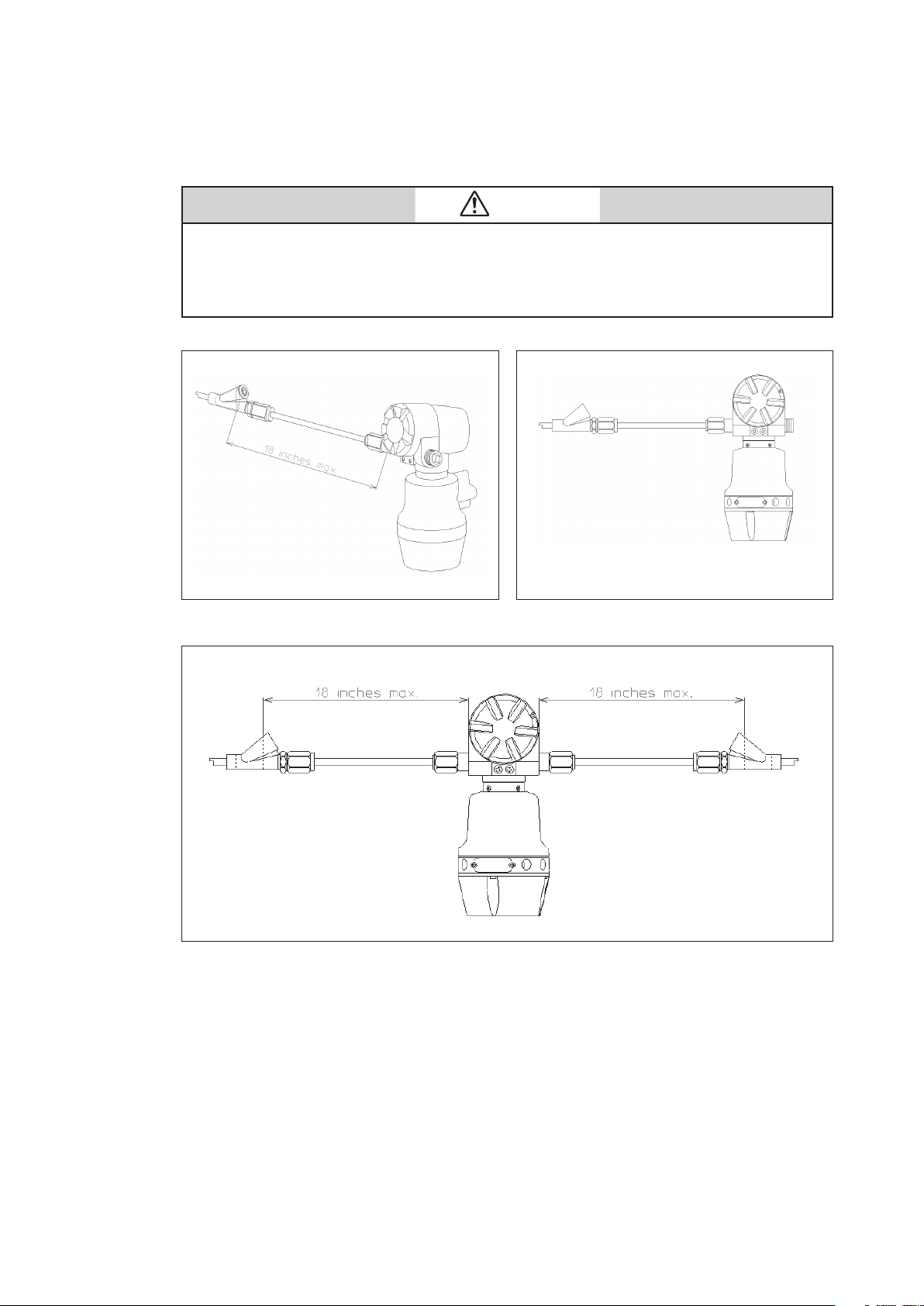
CAUTION
• Install the apparatus only in hazardous (classified) locations for which the apparatus has been
approved.
• Seal each conduit entering the apparatus enclosure within 18 in.(457 mm) from the enclosure.
• Do not open the apparatus enclosure when an explosive atmosphere is present.
Fig. S-1 An example of conduit seal (with stopping plug)
Fig. S-2 An example of conduit seals (without stopping plug)
v
Page 8

1. Class I, Division 1 locations
1.1 Wiring methods
• readed rigid metal conduit, threaded steel intermediate metal conduit,
or Type MI cable with termination ttings approved for the location, can
be employed
• readed joints must be made up with at least ve threads fully engaged.
• Boxes, ttings, and joints must be approved for Class I, Division 1.
1.2 Sealing
• Each conduit entering the apparatus enclosure is required to be sealed
within 18 in. (457 mm) from the enclosure.
• e sealing of each conduit can be provided with a sealing tting approved
for class I locations.
• Sealing compound must be approved and must not have a melting point of
less than 93° (200°F).
• e minimum thickness of the sealing compound should not be less than the
trade size of the conduit and, in no case, less than 5/8 in.(16 mm).
• Splices and taps cannot be made in the ttings.
2. Class I, Division 2 locations
2.1 Wiring methods
• readed rigid metal conduit, threaded steel intermediate metal conduit,
enclosed gasketed busways, or Type PLTC cable in accordance with the
provisions of remote-control, signaling, and power-limited circuits (see
NEC, Article 725), or Type ITC cable in cable trays, in raceways, supported
by messenger wire, or directly buried where the cable is listed for this use;
Type MI, MC, MV, or TC cable with approved termination ttings can be
employed.
• Boxes, ttings, and joints are not required to be explosionproof.
2.2 Sealing
• Each conduit entering the apparatus enclosure is required to be sealed as
shown in 1.2.
3. Class II, Division 1 locations
3.1 Wiring methods
• readed rigid metal conduit, threaded steel intermediate metal conduit,
or Type MI cable with termination ttings approved for the location, can
be employed.
• Boxes and ttings must be dusttight.
3.2 Sealing
• Where a raceway provides communication between the apparatus enclosure
and an enclosure that is not required to be dust-ignitionproof, suitable means
must be provided to prevent the entrance of dust into the dust-ignitionproof
enclosure through the raceway. One of the following means can be used: (1)
a permanent and eective seal; (2) a horizontal raceway not less than 10
(3.05 m) long; or (3) a vertical raceway not less than 5 (1.52 m) long and
extending downward from the dust-ignitionproof enclosure.
• Seals are not required to be explosionproof.
vi
Page 9

4. Class II, Division 2 locations
4.1 Wiring methods
• Rigid metal conduit, intermediate metal conduit, electrical metallic
tubing, dust-tight wireways, or Type MC or MI cable with approved
termination fittings, or Type PLTC in cable trays, or Type ITC in cable
trays, or Type MC or TC cable installed in ladder, ventilated trough,
or ventilated channel cable trays in a single layer, with a space not less
than the larger cable diameter between the two adjacent cables, can be
employed.
• All boxes and ttings must be dusttight.
4.2 Sealing
• Sealing means must be provided as shown in 3.2.
5. Class III, Division 1 locations
5.1 Wiring methods
• Rigid metal conduit, rigid non-metallic conduit, intermediate metal
conduit, electrical metallic tubing, dust-tight wireways, or Type MC or
MI cable with approved termination ttings, can be employed.
• All boxes and ttings must be dusttight.
5.2 Sealing
• Sealing means are not required.
6. Class III, Division 2 locations
6.1 Wiring methods
• Wiring methods must comply with 5.1.
6.2 Sealing
• Sealing means are not required.
vii
Page 10

(3) NEPSI Flameproof and Dust Certications
Heat Value Gas Chromatograph model HGC303, manufactured by Azbil
Corporation, has been approved by National Supervision and Inspection Center for
Explosion Protection and Safety of Instrumentation (NEPSI) in accordance with
the following standards:
GB3836.1-2010 Electrical apparatus for explosive gas atmospheres
Part 1: General requirements
GB3836.2-2010 Electrical apparatus for explosive gas atmospheres
Part 2: Flameproof enclosure “d”
GB12476.1-2013
Part 1: General requirements
GB12476.5-2013
Part 5: Protection by enclosure “tD”
The apparatus are approved with Ex marking of Ex d IIC T6; Ex tD A21 T85°C
IP65. e certicate number is GYJ15.1324X.
1. Requirements for safe use
1.1 e external earthing terminal shall be connected to the ground reliably at site.
1.2 e ambient temperature range is -40°C to +60°C.
1.3 e cable entry holes have to be connected by means of suitable cable entries
with type of protection of Ex d IIC and Ex tD A21, which are covered by a
separate examination certicate. Unwanted entry holes shall be blocked by blind
plugs. Aer installation of the cable entry, the whole apparatus shall reach IP65.
1.4 Rated supply voltage: (24±15%)Vd.c
1.5 e warning “Do not open while the circuit is alive” must be obeyed when the
product is used in the explosive gas area.
1.6 Regular cleanness shall be conducted to avoid the deposit of the dust.
1.7 The gas that may cause the corrosion effect to the aluminum alloy shall be
excluded at site.
1.8 End users are forbidden to change the configuration to ensure the explosion
protection performance of the product.
1.9 When installation, operation and maintenance the product, users should
comply with the relevant requirements of the product instruction manual and
the following standards:
GB3836.13-2013 “Electrical apparatus for explosive gas atmospheres Part 13: Repair
GB3836.15-2000 “Electrical apparatus for explosive gas atmospheres Part 15:
GB3836.16-2006 “Electrical apparatus for explosive gas atmospheres Part 16: Inspection
GB50257-1996 “Code for construction and acceptance of electric device for
GB12476.2-2010 “Electrical apparatus for use in the presence of combustible dust
GB15577-2007 “Safety regulations for the protection of dust explosion”.
Electrical apparatus for use in the presence of combustible dust
Electrical apparatus for use in the presence of combustible dust
and overhaul for apparatus used in explosive gas atmospheres”
Electrical installations in hazardous area (other than mines)”
and maintenance of electrical installation (other than mines)”.
explosion atmospheres and fire hazard electrical equipment
installation engineering”
Part A-1: Electrical apparatus protected by enclosures and surface
temperature limitation-Selection, installation and maintenance”
2. Special condition for safe use
e cover has at least 7.9 engaged threads.
viii
Page 11

EMC caution
1. Electromagnetic environment
The model HGC303 is intended to be used in an industrial electromagnetic
environment.
2. Electromagnetic immunity conditions
Specication: During test, SCV deviation is less than or equal to 1MJ/m3.
ix
Page 12

x
Page 13

Table of Contents
Chapter 1. Introduction . . . . . . . . . . . . . . . . . . . . . . . . . . . . . . . . . . . . . . . . . . . . . . . . . . . . . . . . .1-1
1-1. Definition of terms . . . . . . . . . . . . . . . . . . . . . . . . . . . . . . . . . . . . . . . . . . . . . . . . . . . . . . . . . . . . . . . . . . . . 1-1
1-2. General . . . . . . . . . . . . . . . . . . . . . . . . . . . . . . . . . . . . . . . . . . . . . . . . . . . . . . . . . . . . . . . . . . . . . . . . . . . . . . 1-3
1-3. Model HGC303 measuring system . . . . . . . . . . . . . . . . . . . . . . . . . . . . . . . . . . . . . . . . . . . . . . . . . . . . . 1-4
1-4. Model No. . . . . . . . . . . . . . . . . . . . . . . . . . . . . . . . . . . . . . . . . . . . . . . . . . . . . . . . . . . . . . . . . . . . . . . . . . . . . 1-5
1-5. Model HGC303 Structure . . . . . . . . . . . . . . . . . . . . . . . . . . . . . . . . . . . . . . . . . . . . . . . . . . . . . . . . . . . . . 1-6
1-6. Fieldbus communication system . . . . . . . . . . . . . . . . . . . . . . . . . . . . . . . . . . . . . . . . . . . . . . . . . . . . . . 1-7
Chapter 2. Installation . . . . . . . . . . . . . . . . . . . . . . . . . . . . . . . . . . . . . . . . . . . . . . . . . . . . . . . . . . .2-1
2-1. Unpacking and storing. . . . . . . . . . . . . . . . . . . . . . . . . . . . . . . . . . . . . . . . . . . . . . . . . . . . . . . . . . . . . . . . 2-1
2-2. Installing the model HFA100 . . . . . . . . . . . . . . . . . . . . . . . . . . . . . . . . . . . . . . . . . . . . . . . . . . . . . . . . . . 2-3
2-3. HGM Installation . . . . . . . . . . . . . . . . . . . . . . . . . . . . . . . . . . . . . . . . . . . . . . . . . . . . . . . . . . . . . . . . . . . . . . 2-3
2-3-1. Computer system requirements . . . . . . . . . . . . . . . . . . . . . . . . . . . . . . . . . . . . . . . . . . . . . . . . 2-3
2-3-2. Settings for Windows 10 . . . . . . . . . . . . . . . . . . . . . . . . . . . . . . . . . . . . . . . . . . . . . . . . . . . . . . . 2-4
2-3-3. HGM software installation . . . . . . . . . . . . . . . . . . . . . . . . . . . . . . . . . . . . . . . . . . . . . . . . . . . . . 2-13
2-3-4. .NET framework 4.0 installation . . . . . . . . . . . . . . . . . . . . . . . . . . . . . . . . . . . . . . . . . . . . . . . . 2-16
2-3-5. Microsoft Visual C++ runtime installation . . . . . . . . . . . . . . . . . . . . . . . . . . . . . . . . . . . . . .2-18
2-3-6. Setting the folder access rights . . . . . . . . . . . . . . . . . . . . . . . . . . . . . . . . . . . . . . . . . . . . . . . .2-21
2-4. Fieldbus installation . . . . . . . . . . . . . . . . . . . . . . . . . . . . . . . . . . . . . . . . . . . . . . . . . . . . . . . . . . . . . . . . . 2-25
2-4-1. Fieldbus requirements . . . . . . . . . . . . . . . . . . . . . . . . . . . . . . . . . . . . . . . . . . . . . . . . . . . . . . . . 2-25
2-4-2. Fieldbus wiring . . . . . . . . . . . . . . . . . . . . . . . . . . . . . . . . . . . . . . . . . . . . . . . . . . . . . . . . . . . . . . . 2-28
2-5. Model HGC303 installation . . . . . . . . . . . . . . . . . . . . . . . . . . . . . . . . . . . . . . . . . . . . . . . . . . . . . . . . . . . 2-29
2-5-1. Installation site . . . . . . . . . . . . . . . . . . . . . . . . . . . . . . . . . . . . . . . . . . . . . . . . . . . . . . . . . . . . . . .2-29
2-5-2. Model HGC303 dimensions . . . . . . . . . . . . . . . . . . . . . . . . . . . . . . . . . . . . . . . . . . . . . . . . . . .2-30
2-5-3. Model HGC303 installation example . . . . . . . . . . . . . . . . . . . . . . . . . . . . . . . . . . . . . . . . . . .2-31
2-5-4. Model HGC303 piping . . . . . . . . . . . . . . . . . . . . . . . . . . . . . . . . . . . . . . . . . . . . . . . . . . . . . . . .2-32
2-5-5. Model HGC303 wiring . . . . . . . . . . . . . . . . . . . . . . . . . . . . . . . . . . . . . . . . . . . . . . . . . . . . . . . . . 2-34
Chapter 3. Operation . . . . . . . . . . . . . . . . . . . . . . . . . . . . . . . . . . . . . . . . . . . . . . . . . . . . . . . . . . . .3-1
3-1. Starting up the model HGC303 . . . . . . . . . . . . . . . . . . . . . . . . . . . . . . . . . . . . . . . . . . . . . . . . . . . . . . . . 3-1
3-1-1. Secondary pressure and flow set . . . . . . . . . . . . . . . . . . . . . . . . . . . . . . . . . . . . . . . . . . . . . . . 3-1
3-1-2. Piping leak check . . . . . . . . . . . . . . . . . . . . . . . . . . . . . . . . . . . . . . . . . . . . . . . . . . . . . . . . . . . . . . 3-1
3-1-3. Power on . . . . . . . . . . . . . . . . . . . . . . . . . . . . . . . . . . . . . . . . . . . . . . . . . . . . . . . . . . . . . . . . . . . . . . 3-2
3-1-4. Model HGC303 leak check . . . . . . . . . . . . . . . . . . . . . . . . . . . . . . . . . . . . . . . . . . . . . . . . . . . . . . 3-3
3-2. Stopping the model HGC303 . . . . . . . . . . . . . . . . . . . . . . . . . . . . . . . . . . . . . . . . . . . . . . . . . . . . . . . . . . 3-4
3-3. HGM operation . . . . . . . . . . . . . . . . . . . . . . . . . . . . . . . . . . . . . . . . . . . . . . . . . . . . . . . . . . . . . . . . . . . . . . . 3-5
3-3-1. HGM connection with model HFA100 and HDM303 . . . . . . . . . . . . . . . . . . . . . . . . . . . . . 3-6
3-3-2. Starting up the HGM with model HFA100 . . . . . . . . . . . . . . . . . . . . . . . . . . . . . . . . . . . . . . . 3-7
3-3-3. HGM Main menu . . . . . . . . . . . . . . . . . . . . . . . . . . . . . . . . . . . . . . . . . . . . . . . . . . . . . . . . . . . . . . 3-12
3-3-4. Set up HGM . . . . . . . . . . . . . . . . . . . . . . . . . . . . . . . . . . . . . . . . . . . . . . . . . . . . . . . . . . . . . . . . . . . 3-13
3-3-5. User’s mode menu and commands . . . . . . . . . . . . . . . . . . . . . . . . . . . . . . . . . . . . . . . . . . . .3-19
3-3-6. Main displays of HGM . . . . . . . . . . . . . . . . . . . . . . . . . . . . . . . . . . . . . . . . . . . . . . . . . . . . . . . . .3-20
3-3-7. Report . . . . . . . . . . . . . . . . . . . . . . . . . . . . . . . . . . . . . . . . . . . . . . . . . . . . . . . . . . . . . . . . . . . . . . . . 3-25
3-3-8. Configuration mode . . . . . . . . . . . . . . . . . . . . . . . . . . . . . . . . . . . . . . . . . . . . . . . . . . . . . . . . . . 3-28
3-3-9. HGM shut down . . . . . . . . . . . . . . . . . . . . . . . . . . . . . . . . . . . . . . . . . . . . . . . . . . . . . . . . . . . . . .3-40
3-4. Calibration . . . . . . . . . . . . . . . . . . . . . . . . . . . . . . . . . . . . . . . . . . . . . . . . . . . . . . . . . . . . . . . . . . . . . . . . . . 3-41
3-4-1. Calibration gas requirement . . . . . . . . . . . . . . . . . . . . . . . . . . . . . . . . . . . . . . . . . . . . . . . . . . . 3-41
3-4-2. Calibration procedure . . . . . . . . . . . . . . . . . . . . . . . . . . . . . . . . . . . . . . . . . . . . . . . . . . . . . . . . .3-42
3-4-3. Calibration function . . . . . . . . . . . . . . . . . . . . . . . . . . . . . . . . . . . . . . . . . . . . . . . . . . . . . . . . . . . 3-46
3-4-4. Description of component data table . . . . . . . . . . . . . . . . . . . . . . . . . . . . . . . . . . . . . . . . . . 3-48
xi
Page 14

3-4-5. Report . . . . . . . . . . . . . . . . . . . . . . . . . . . . . . . . . . . . . . . . . . . . . . . . . . . . . . . . . . . . . . . . . . . . . . . . 3-49
3-4-6. Calibration methods . . . . . . . . . . . . . . . . . . . . . . . . . . . . . . . . . . . . . . . . . . . . . . . . . . . . . . . . . . 3-50
3-5. GPA mode . . . . . . . . . . . . . . . . . . . . . . . . . . . . . . . . . . . . . . . . . . . . . . . . . . . . . . . . . . . . . . . . . . . . . . . . . . . 3-52
3-5-1. Setting the HGM to GPA . . . . . . . . . . . . . . . . . . . . . . . . . . . . . . . . . . . . . . . . . . . . . . . . . . . . . . . 3-52
3-5-2. Data save . . . . . . . . . . . . . . . . . . . . . . . . . . . . . . . . . . . . . . . . . . . . . . . . . . . . . . . . . . . . . . . . . . . . .3-53
3-5-3. Data edit . . . . . . . . . . . . . . . . . . . . . . . . . . . . . . . . . . . . . . . . . . . . . . . . . . . . . . . . . . . . . . . . . . . . .3-53
3-5-4. File auto saving . . . . . . . . . . . . . . . . . . . . . . . . . . . . . . . . . . . . . . . . . . . . . . . . . . . . . . . . . . . . . . .3-54
3-5-5. Configuration mode . . . . . . . . . . . . . . . . . . . . . . . . . . . . . . . . . . . . . . . . . . . . . . . . . . . . . . . . . . 3-55
3-5-6. User’s mode (GPA) . . . . . . . . . . . . . . . . . . . . . . . . . . . . . . . . . . . . . . . . . . . . . . . . . . . . . . . . . . . . 3-63
3-5-7. Main display panels of HGM (GPA) . . . . . . . . . . . . . . . . . . . . . . . . . . . . . . . . . . . . . . . . . . . . . 3-65
3-5-8. Report (GPA) . . . . . . . . . . . . . . . . . . . . . . . . . . . . . . . . . . . . . . . . . . . . . . . . . . . . . . . . . . . . . . . . . . 3-70
Chapter 4. Maintenance . . . . . . . . . . . . . . . . . . . . . . . . . . . . . . . . . . . . . . . . . . . . . . . . . . . . . . . . .4-1
4-1. Checking and changing the carrier gas . . . . . . . . . . . . . . . . . . . . . . . . . . . . . . . . . . . . . . . . . . . . . . . . 4-1
4-2. Checking and changing the filters in model HGC303 . . . . . . . . . . . . . . . . . . . . . . . . . . . . . . . . . . . 4-1
4-3. Periodical check . . . . . . . . . . . . . . . . . . . . . . . . . . . . . . . . . . . . . . . . . . . . . . . . . . . . . . . . . . . . . . . . . . . . . . 4-1
Chapter 5. Troubleshooting . . . . . . . . . . . . . . . . . . . . . . . . . . . . . . . . . . . . . . . . . . . . . . . . . . . . .5-1
5-1. Connection with PC . . . . . . . . . . . . . . . . . . . . . . . . . . . . . . . . . . . . . . . . . . . . . . . . . . . . . . . . . . . . . . . . . . 5-1
5-2. HGC status on HGM . . . . . . . . . . . . . . . . . . . . . . . . . . . . . . . . . . . . . . . . . . . . . . . . . . . . . . . . . . . . . . . . . . . 5-2
Appendix . . . . . . . . . . . . . . . . . . . . . . . . . . . . . . . . . . . . . . . . . . . . . . . . . . . . . . . . . . . . . . . . . . . . . . . A-1
Terms and Conditions . . . . . . . . . . . . . . . . . . . . . . . . . . . . . . . . . . . . . . . . . . . . . . . . . . . . . . . . . . . S1
xii
Page 15
Chapter 1. Introduction
1-1. Definition of terms
Heat Value Gas Chromatograph (Model HGC303)
The Heat Value Gas Chromatograph measures process gases (N2, CO2,
C1~C6+) that are mainly contained in natural gas, calculates heat value,
density, Wobbe index and compressibility factor, and converts them into
a Fieldbus signal in the field and transmits the signal to a receiver.
Parameters can all be remotely set, adjusted, and self-diagnosed by
using the HGM.
Measuring and calculating methods comply with ISO 6974 Part 4, ISO
6976 and GPA2172.
HGC Data Manager (Model HDM303)
Model HDM303 is Modbus interface unit for model HGC303.
Model HDM303 covers all the function of model HMU303. Model
HDM303 also has a powerful functions.
HGC000
The functions are local display, data storage function, multi
Modbus serial port, multi stream switching, and analog output.
HMU can not be connected together with HDM in the same FB
loop. Only one HMU can be connected in one FB loop with the
HGC. Two or more HDM can be connected in the same FB loop.
For this application, the HDM must be configured first.
Please refer to the model HDM303 User’s Manual for more details.
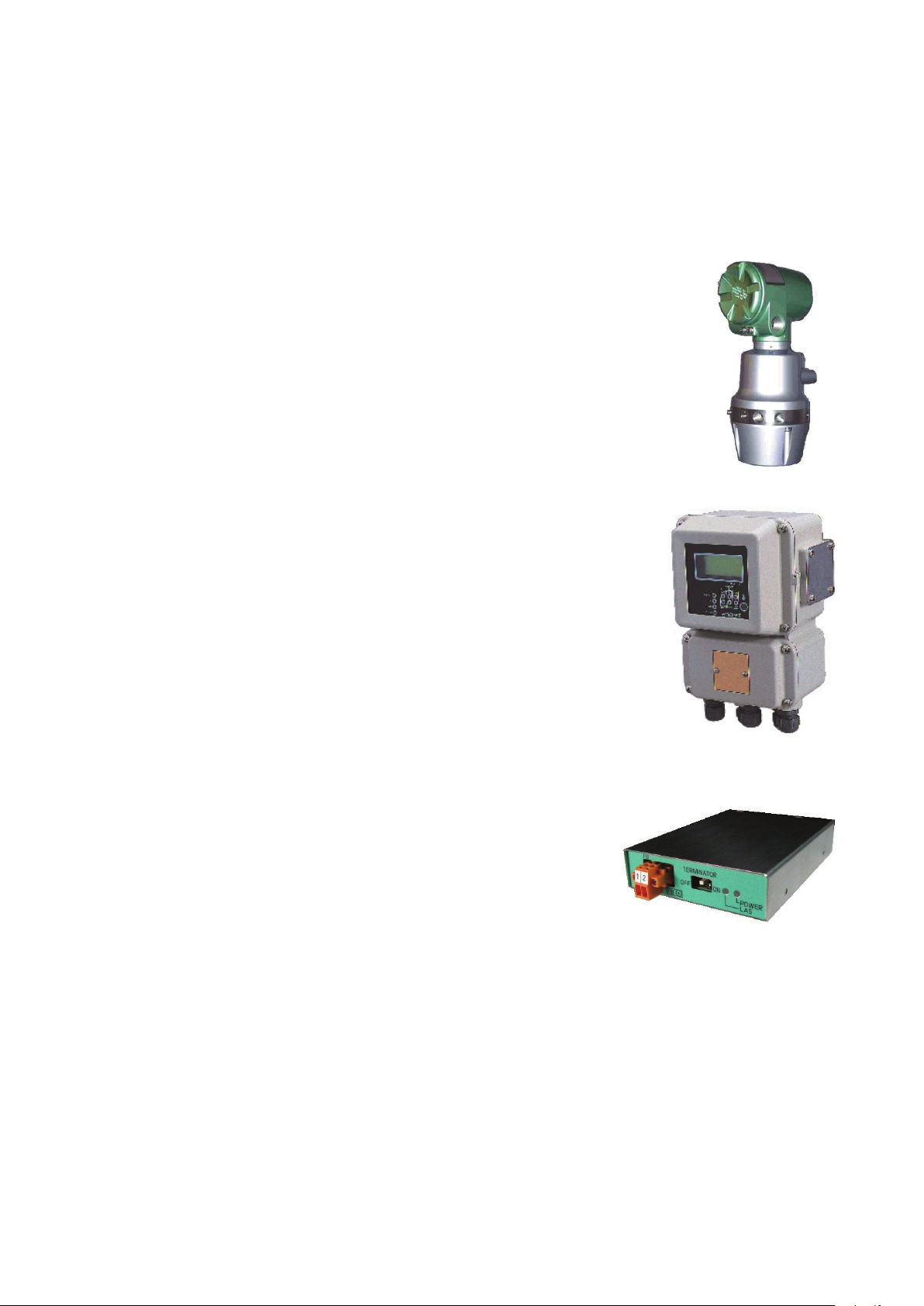
Heat Value Gas Chromatograph Fieldbus Adaptor (Model HFA100)
HFA is an interface used to connect the HGM (HGC
monitor), Windows-based PC application, to Azbil
Corporation’s state of the art analyzer, HGC (Heat value
Gas Chromatograph) that operates on F
fieldbus H1 network. Users are able to configure, monitor
and maintain the HGC all from the PC by simply
connecting the HFA to the Fieldbus network.
OUNDATION
TM
1-1
Page 16

HGC Monitor (HGM)
HGM software is provided as a standard accessory
with the model HGC303.
The model HGC303 Monitor allows the user to
configure and calibrate the model HGC303 as well as
allowing one to monitor a heat value-trend graph.
Moreover, HGM also has a report function for
concise management.
SP (Set Point)
The set value of each variable.
PV (Process variable)
The present value of each variable.
SCV, GCV
Superior Calorific Value, Gross Calorific Value
These parameters are same value of different name.
HGM000001000P
ICV, NCV
Inferior Calorific Value, Net Calorific Value
These parameters are same value of different name.
TCD
Thermal Conductivity Detector
URV
Upper Range Value
LRV
Lower Range Value
Total (Raw)
Total of raw concentration
Component name
C6+: Hexane and heavier gas
C3H8: Propane
i-C4H10: i-Butane
n-C4H10: n-Butane
neo-C5H12: neo-Pentane
i-C5H12: i-Pentane
n-C5H12: n-Pentane
N2: Nitrogen
CH4: Methane
CO2: Carbon dioxide
C2H6: Ethane
1-2
Page 17

1-2. General
The model HGC303 is a gas chromatograph designed to analyze natural gas and is able to
transmit a process variable via a Fieldbus signal.
One can easily adjust configuration data and monitor values such as the heat value by using
the HGM.
The heat value monitoring system, which can be controlled from both the model HGC303 and
HGM, will substantially minimize time, cost and maintenance.
This chapter first describes the measuring system and structure of the model HGC303. After
that, the characteristics and the specifications of Fieldbus are described in detail.
First time users of the model HGC303 should read this chapter carefully and thoroughly.
Components of the model HGC303 system
Before installing the model HGC303, the following components must be prepared:
Hardware
Model HGC303
Model HDM303
Model HFA100
Power supply (24 V DC, 4A min.), Power supply cable
Fieldbus cable (See “2-4-1. Fieldbus requirements” on page 2-25)
Flow meter for process gas
(A flow meter for methane should be used scale: 0 - 100 ml/min.)
Laptop or desktop PC
(See “2-3-1. Computer system requirements” on page 2-3 for detail)
Helium gas for carrier gas and valve operating gas
Calibration gas
1/8 or 1/4 inch stainless steel (SS) tubing
Fitting for piping (1/4 NPT male connector 5 or 6 pieces.... For HGC)*
Software
Microsoft Windows 7 (32-bit type, 64-bit type) / Microsoft Windows 10 (64-bit type)
HGM
Note *: For satisfying TestSafe Flameproof Certification or IP65, six 1/4 NPT male connectors
are required.
1-3
Page 18
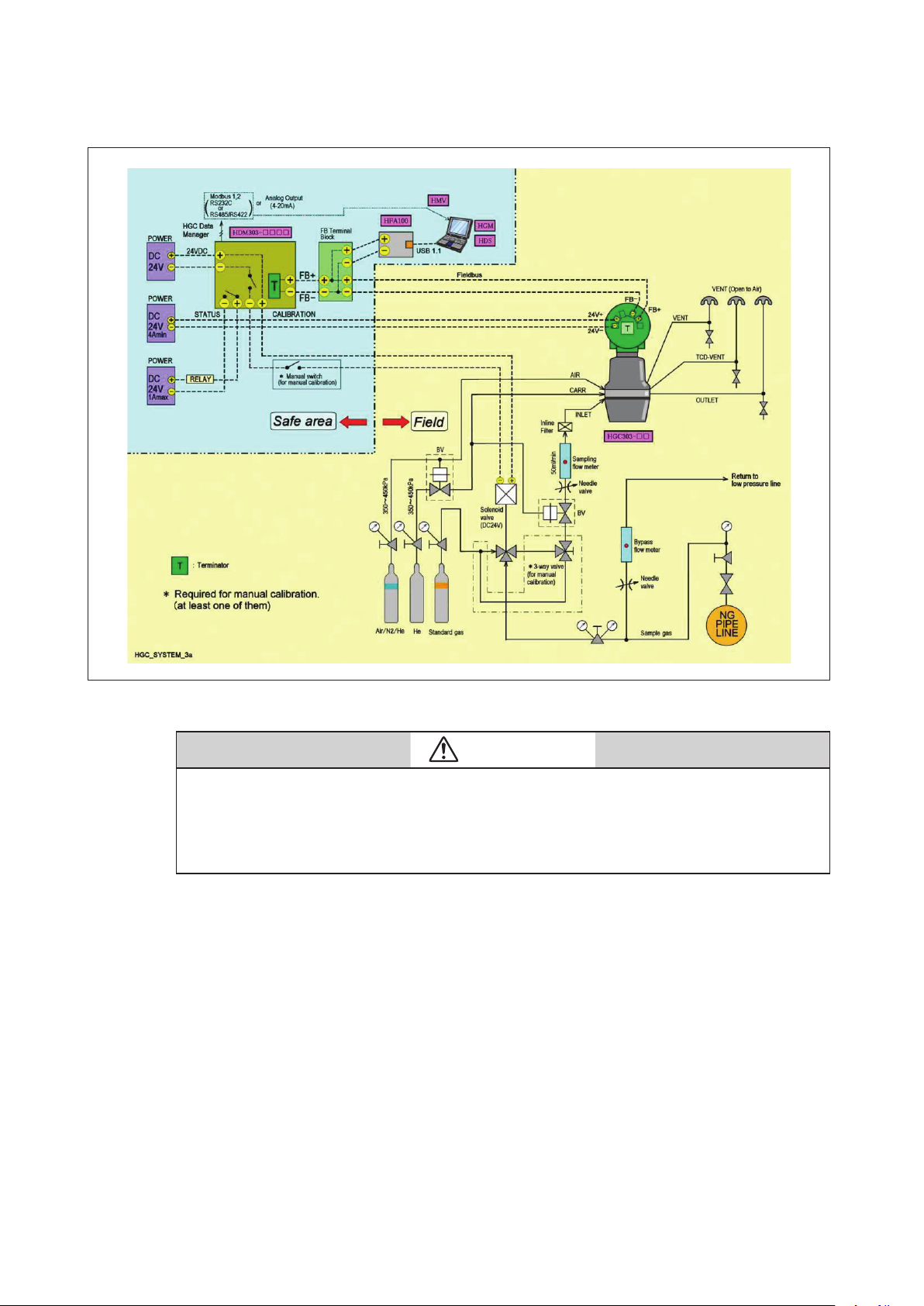
1-3. Model HGC303 measuring system
Fig. 1-1 Model HGC303 measuring system diagram
CAUTION
A block valve is a kind of air actuator valve. It is used mainly for the protection of the TCD and
columns.
It works as sample shut-off valve when the pressure of the carrier gas or air supply is lower than
approximately 294 kPa.
Azbil Corporation recommends that it should be installed.
The Heat Value Gas Chromatograph measures process gases (N2, CO2, C1~C6+) that
are mainly contained in natural gas, calculates heat value, density, Wobbe index and
compressibility factor, and converts them into a Fieldbus signal in the field and trans- mits the
signal to receivers.
Parameters can be remotely set, adjusted, and self-diagnosed with the HGM.
1-4
Page 19
1-4. Model No.
HGC303-I II
I Conduit entry 1/2 NPT female 1
II Explosion-protection ISSeP/ATEX flameproof E ISO
Heat Value Gas Chromatograph
Gas connection 1/4 NPT female Calculation method
NEPSI flameproof N
TestSafe flameproof S
JIS flameproof *
Ordinary type
FM flameproof F GPA
CSA flameproof C
Note *: Special model.
Note +: Default range is suitable for High calorie LNG.
+
+
J
H
1-5
Page 20
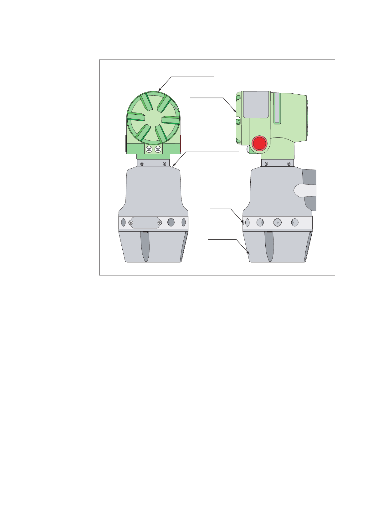
1-5. Model HGC303 Structure
HGC000004000D
Terminal housing
Terminal cover
Analyzer unit housing
Manifold
Oven cover
Fig. 1-2 Main parts of Model HGC303
1 Terminal housing ..........Terminal box for wiring.
2 Analyzer unit housing ..Proportional valve, solenoid valve, TCD sensor are located here.
3 Manifold .........................Connection parts for gas inlet and outlet line
4 Oven cover .....................Analyzer valve and column system are found inside the cover.
1-6
Page 21

1-6. Fieldbus communication system
The model HGC303 uses F
between other devices.
The F
OUNDATION
communication system which interconnects field equipment such as sensors, actuators and
controllers.
The F
OUNDATION
manufacturers in Europe, North America and Asia Pacific.
OUNDATION
TM
fieldbus is an open, 2-wire, multi-drop, two-way digital
TM
fieldbus is supported by a worldwide network of customers and
TM
fieldbus technology to transfer information
F
OUNDATION
F
OUNDATION
(1) F
OUNDATION
TM
fieldbus http://www.fieldbus.org/
TM
fieldbus literature
TM
fieldbus Technical overview (FD-043)
(2) Fieldbus Installation & Planning Guide (AG-165)
(3) F
OUNDATION
TM
fieldbus Application Guide
31.25kbit/s Wiring and Installation (AG-140)
(4) F
OUNDATION
TM
fieldbus Application Guide
31.25kbit/s Intrinsically Safe Systems (AG-163)
1-7
Page 22

1-8
Page 23
Chapter 2. Installation
This chapter guides you through the procedures for installing of your hardware and software.
2-1. Unpacking and storing
Unpacking the model HGC303
Your model HGC303 is a precision instrument and should be handled with care to prevent any
damage to it or breaking it.
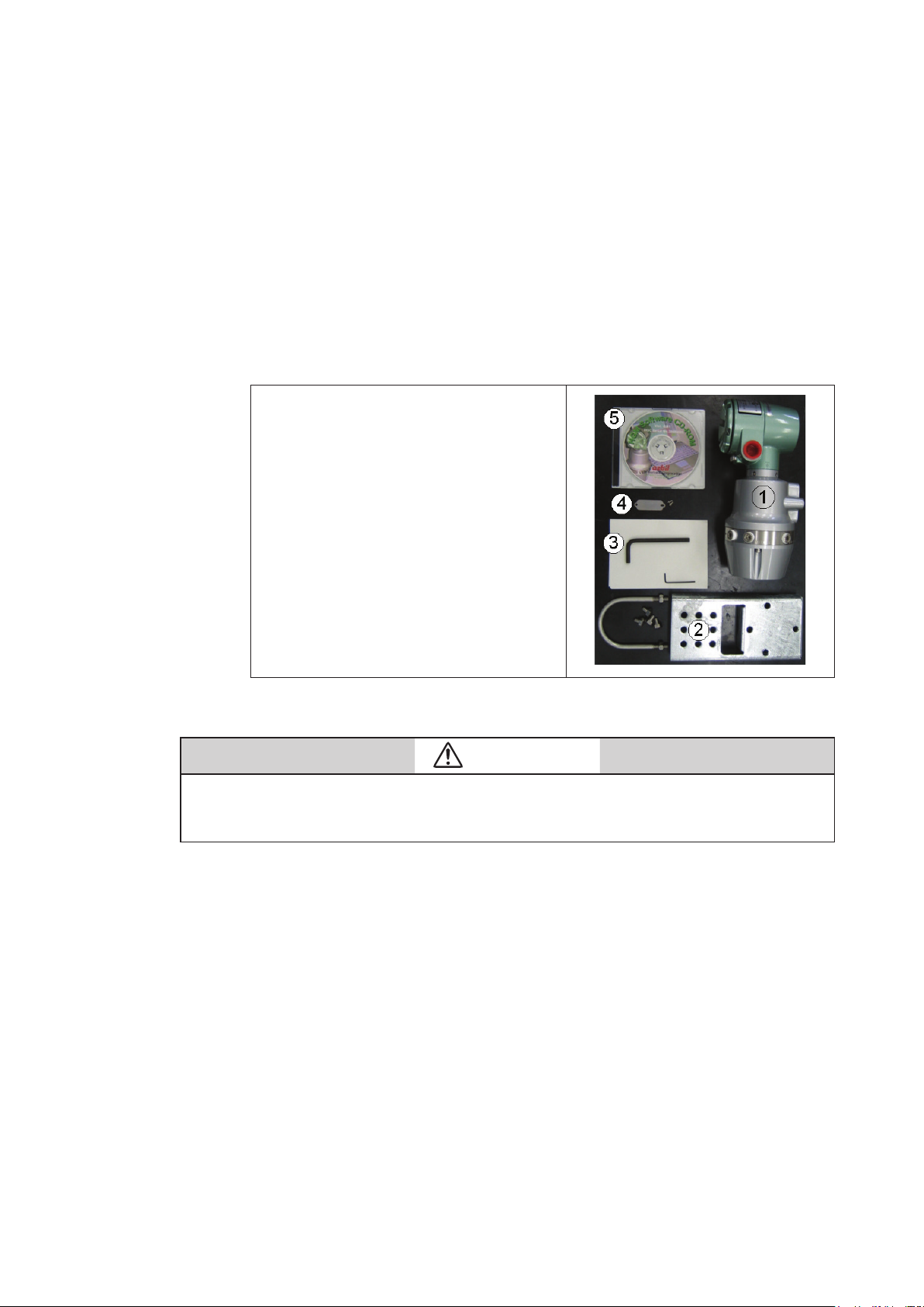
After unpacking the model HGC303, verify that the following items are included
Package items
(1) Model HGC303
(2) Mounting bracket set
(3) Wrench for seal plug
(4) Tag number plate set
(5) CD-ROM including HGM software
and user’s manual
(6) EC declaration of conformity and
safety instructions *
Note *: It is packed with model HGC303-_E only.
CAUTION
Exposing the model HGC303 to the atmosphere might cause deterioration of the column.
Therefore, the model HGC303 has been packed and shipped in a protective bag with a desiccant.
Install and operate the model HGC303 immediately after breaking the seal.
Inquires
If you have any questions regarding the specifications of your model HGC303, contact one
of the Azbil Corporation products service offices or contact your nearest Azbil Corporation
representative.
When making an inquiry, make sure to provide the model number and product number of
your model HGC303.
2-1
Page 24

Storing the model HGC303
The model HGC303 should be stored:
- indoor at storage temperature (-40 to 70°C); humidity (up to 95%RH)
- in a place safe from vibration or shock.
- in the same packing as it was shipped in.
Model HGC303 that has been used should be stored by following procedures below.
Step Action
1 Make sure no process gas remain in the model HGC303.
2 Purge the model HGC303 with helium gas.
Insert metal plugs into all the inlets and outlets for carrier gas, valve operating
3
gas and process gas except VENT (valve operating gas outlet) in order to keep
moisture out.
4 Pack it as it was when it was originally received.
Store the model HGC303 indoors at normal temperature and humidity in a
5
place safe from vibration or shock.
2-2
Page 25

2-2. Installing the model HFA100
To collect data from HGC, HGM needs the HFA100 (Heat value gas chromatograph fieldbus
adapter) as a data converter. First, for hardware installation, see the user’s manual for
HFA100.
Note: This manual is for the use of HFA100 version 3.0 or later. For combinations of HFA100
versions and corresponding PC software versions, see “Software Compatibility” in the
Appendix.
2-3. HGM Installation
2-3-1. Computer system requirements
(1) Operating system: Windows 7 (32-bit type, 64-bit type) / Windows 10 (64-bit type)
(2) Disk storage: 20 GB free space minimum
(3) CD-ROM drive (used only during installation)
(4) USB 2.0 or later
Note: For Windows 7, use Service Pack 1 and the latest updates. For Windows 10, use
Professional or Enterprise Edition version 1709 or later.
2-3
Page 26

2-3-2. Settings for Windows 10
When using Windows 10 and running the HGM online, make sure to configure the Windows
Update setting so that the Internet is not connected.
Stopping services
(1) Left-click the [Start] icon and then click the [Services] menu from the
[Windows Administrative Tools]menu.
2-4
Page 27
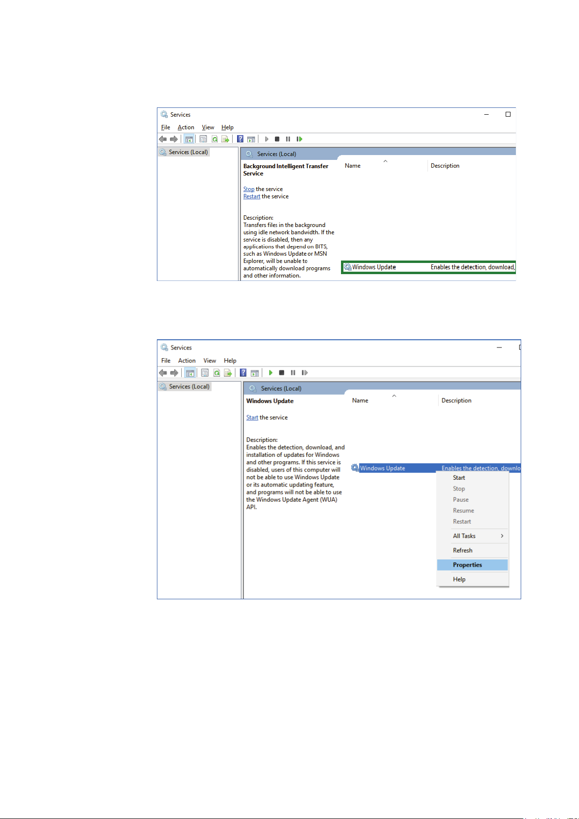
(2) Click in the [Services] screen, and then right-click [Windows Update].
(3) On the [Services] screen, right-click [Windows Update] and then click [Properties] in the
menu that is displayed.
2-5
Page 28
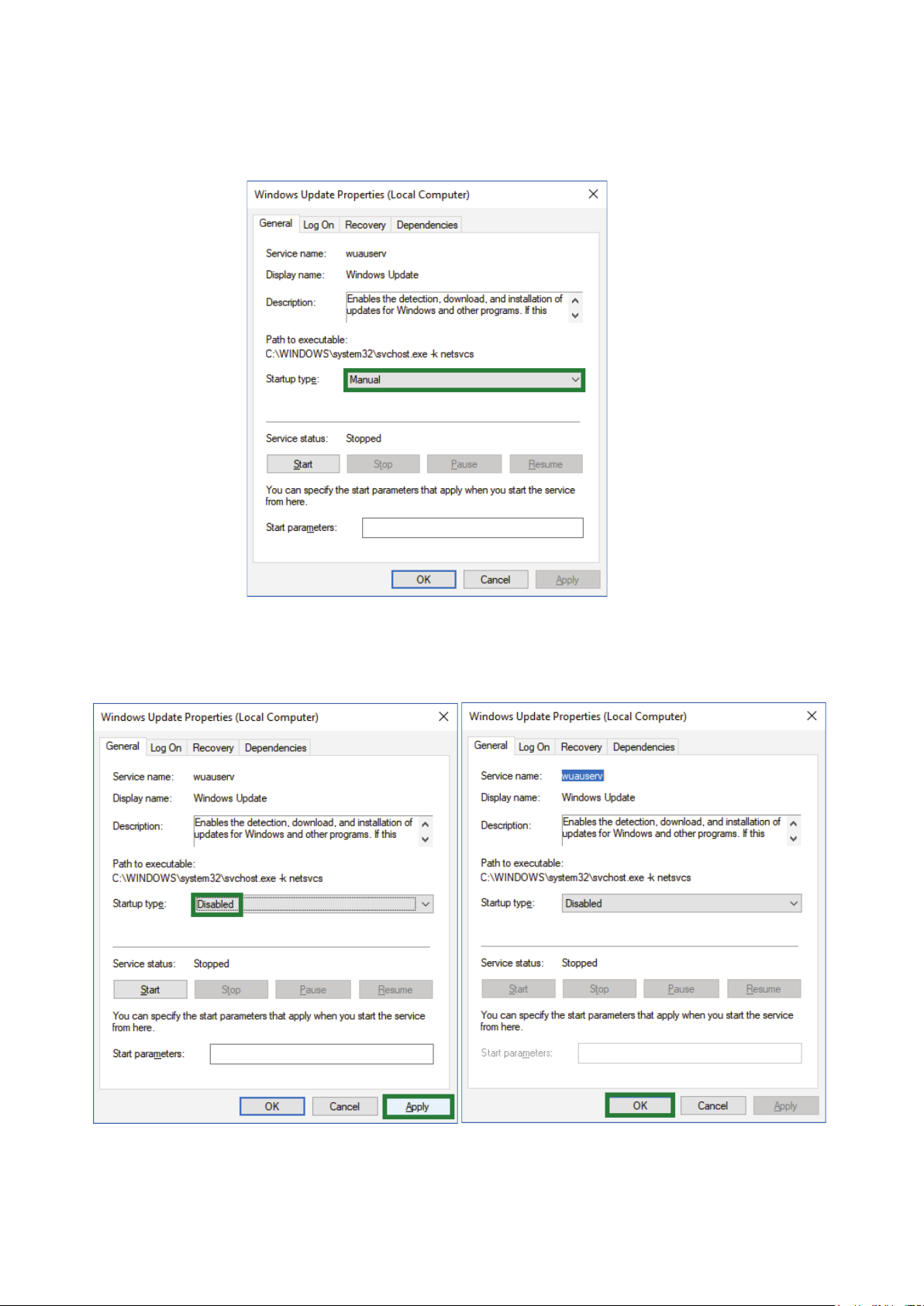
(4) On the [Windows Update Properties] screen, click [Startup type] and then switch it to [Disabled].
If [Service Status] is [Run], switch it to [Stopped].
(5) On the [Windows Update Properties] screen, with the [Startup type] selected as
[Disabled], click the [Apply] button and then the [OK] button.
2-6
Page 29
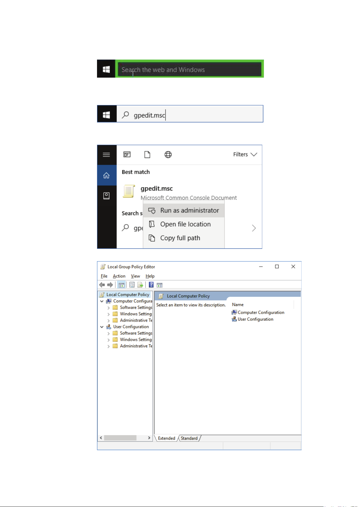
(6) Click on the search section at the bottom left of the window.
(7) Click in the Search screen and enter “gpedit.msc.”
(8) Right-click the displayed program and click “Run with Administrator Privileges.”
(9) The [Local Group Policy Editor screen] opens.
2-7
Page 30
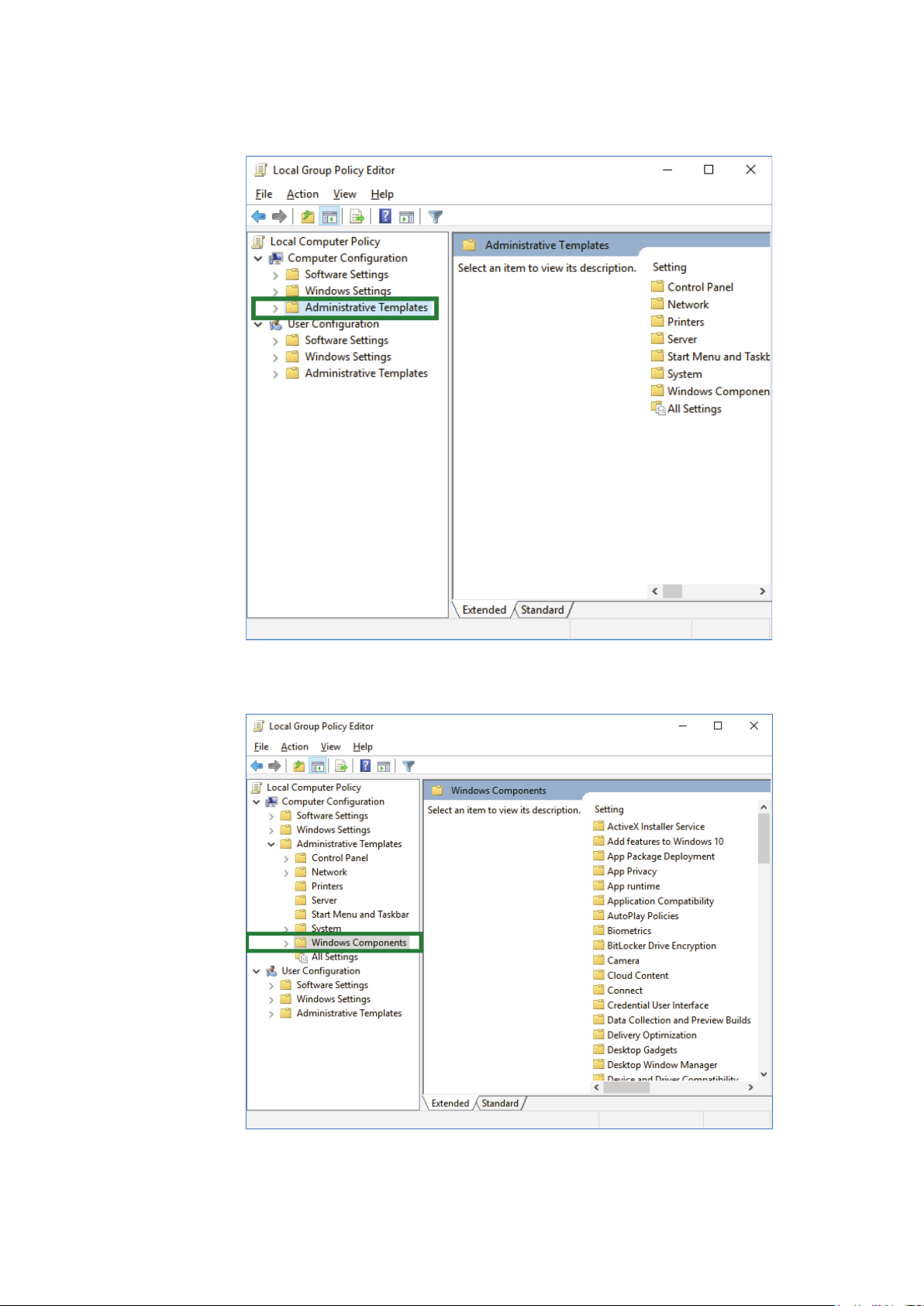
(10) In the [Local Group Policy Editor] screen, click [Computer Configuration] >
[Administrative Templates] in the menu tree on the left.
(11) Click [Windows Components] in the [Local Group Policy Editor] screen.
2-8
Page 31

(12) Double-click [Windows Update] in the [Local Group Policy Editor] screen.
(13) Double-click [Configure Automatic Update] in the [Local Group Policy Editor] screen.
(14) Click the [Disabled] button in the [Configure Automatic Update] screen.
2-9
Page 32

(15) Click the [OK] button in the [Configure Automatic Update] screen.
(16) In the Settings screen, click the [Update & security] icon.
2-10
Page 33

(17) Open the [Windows Update] item list.
(18) In the [Windows Update] items list, click [Advanced options].
2-11
Page 34

(19) Below the [Choose how updates are installed] section, if “Some settings are managed by
your organization” is displayed and grayed out, the settings for Windows 10 are complete.
2-12
Page 35

2-3-3. HGM software installation
Installing the HGM.
Note: We recommend always using the latest version of the HGM software. It is supplied in
HGC CD-ROM.
(1) Make sure Windows has been installed.
(2) Start PC. Be sure to Log On your PC with Administrator Account.
(3) Insert the CD-ROM that is supplied with HGC into the CD-ROM drive.
(4) Double-click the [HGMx.xx_setup] folder.
(5) Double-click the [setup.exe] file.
(6) If the User Account Control dialog box appears, click [Yes] button.
Fig. 2-1 UAC dialog box
2-13
Page 36

(7) HGM installer will appear, click [OK] button.
Fig. 2-2 Setup message
(8) The following screen will appear, click PC figure button.
Fig. 2-3 HGM installation location
2-14
Page 37

(9) The following screen will appear, click [Continue] button.
Fig. 2-4 Group name
If a version conflict message appears, select [Yes].
(10) Installation is complete once the message below appears on your screen. Click [OK]
button.
Fig. 2-5 Complete installation
2-15
Page 38

2-3-4. .NET framework 4.0 installation
Do the installation if the OS is Windows 7
Microsoft .NET framework 4.0 or later is required to run HGM. If Microsoft .NET framework
4.0 or later is not installed on the PC, install it using the following proce- dure.
(1) Make sure Windows has been installed.
(2) Start PC. Be sure to Log On your PC with Administrator Account.
(3) Insert the CD-ROM that is supplied with HGC into the CD-ROM drive.
(4) Double-click the [dotNet Framework 4.0] folder.
(5) Double-click the [dotNetFx40_Full_x86_x64.exe] file.
(6) If the User Account Control dialog box appears, click [Yes] button.
Fig. 2-6 UAC dialog box
2-16
Page 39

(7) Setup program will start.
Fig. 2-7 .NET framework 4.0 installation progress
Check the license acceptance check box and click the [Install] button.
(8) Installation will start. It may take a few minutes until completion.
Fig. 2-8 .NET framework 4.0 installation progress
2-17
Page 40

(9) Installation is complete once the message below appears on your screen. Click [Finish]
button.
Fig. 2-9 Complete installation
2-3-5. Microsoft Visual C++ runtime installation
The runtime component for Microsoft Visual C++ 2010 is required for HGM execution. If it is
not installed on the PC, install it using the following procedure.
(1) Make sure Windows has been installed.
(2) Start PC. Be sure to Log On your PC with Administrator Account.
(3) Insert the CD-ROM that is supplied with HGC into the CD-ROM drive.
(4) Double-click the [vc_runtime2010] folder.
(5) Double-click the [vcredist_x86.exe] file.
(6) If the User Account Control dialog box appears, click [Yes] button.
2-18
Page 41

Fig. 2-10 UAC dialog box
(7) Setup program will start.
Fig. 2-11 VC++2010 runtime license agreement
Check the license acceptance check box and click the [Install] button.
2-19
Page 42

(8) Installation will start. Please wait a moment.
Fig. 2-12 VC++2010 runtime installation progress
(9) Installation is complete once the message below appears on your screen. Click [Finish]
button.
Fig. 2-13 Complete installation
2-20
Page 43

2-3-6. Setting the folder access rights
When executing HGM on a Windows 7 or later PC, full access rights for the following
program folders are required.
32bit type operation system: C:\Program Files (x86)\HGM
64bit type operation system: C:\Program Files\HGM
Note: Executing the program without this setting will cause a virtual folder problem caused
by Windows User Account Control (UAC). Refer to troubleshooting “5-1. Connection
with PC.”
Set the access rights by taking the following steps.
(1) Start PC. Be sure to Log On your PC with Administrator Account.
(2) Use Windows Explorer, select [HGM] folder, right click and select [Properties].
Fig. 2-14 HGM folder
2-21
Page 44

(3) HGM Properties, select [Security] tab and click [Edit] button.
Fig. 2-15 HGM folder properties
2-22
Page 45

(4) Permissions for HGM, select [Users] in Group or user names.
Fig. 2-16 Permissions for HGM folder
2-23
Page 46

(5) Permissions for HGM, check Allow Full control in Permissions for Users, then click
[Apply] button and click [OK] button.
Fig. 2-17 Permissions for HGM folder
2-24
Page 47

(6) HGM Properties, click [OK] button.
Note: If the HGM folder has already been created under C:\Users\User_name\AppData\Local\
VirtualStore, the HGM software may not work properly. Move the data in the HGM
folder to other place, or delete the HGM folder.
2-4. Fieldbus installation
2-4-1. Fieldbus requirements
Fieldbus components and characteristics
Cable
Various types cables are usable for fieldbus.
Type A is the preferred fieldbus cable.
Azbil Corporation recommends type A as the fieldbus cable to use.
Fig. 2-18 HGM folder properties
2-25
Page 48

The table below describes the type of cable and its maximum length, which is specified in the
IEC 1158-2/ISA S50.02 Physical Layer Standard.
Table 2-1. Fieldbus cable description
Type Cable description Size Maximum length
2
A Shielded, twisted pair #18 AWG (0.8 mm
Structure: twisted pair cable with overall shield
Detailed specifications of the Type A cable at 25°C are as follows;
a) Characteristic impedance: Z0 at 31.25 kHz = 100 ohm +/- 20%
b) Maximum attenuation at 39 kHz = 3.0 db/m
c) Maximum capacitive unbalance to shield = 2 nF/km
d) Maximum DC resistance (per conductor) = 22 ohm/km
e) Maximum propagation delay change 7.8 kHz to 39 kHz = 1.7 us/km
f) Conductor cross-sectional area (wire size) = 0.8 mm
g) Minimum shield coverage shall be 90%
) 1900m (6232 ft.)
2
(#18 AWG)
Support
Conductor
Insulator
Taping
Shield foil
Shield wire
Shield net
Jacket
Fig. 2-19 Example of Type A fieldbus cable structure
Terminators
A terminator is an impedance matching module used near or at the end of a transmission line.
Terminators prevent distortion and signal loss.
A terminator shall be located at both ends of a trunk cable, connected from one signal
conductor to the other.
A trunk is the longest cable path between any two devices on the fieldbus network. ONLY
TWO terminators are required per fieldbus segment.
No connection shall be made between the terminator and cable shield.
2-26
Page 49

The terminator impedance value shall be 100 ohm +/- 2% over a frequency range of 7.8 kHz to
39 kHz.
The model HGC303 and model HDM303 have a terminator at the fieldbus connection port
therefore an additional terminator is not required.
Terminal blocks
The terminal blocks can be the same as those used for 4-20mA.
Connectors
D-sub 9P connector is as specified for standard fieldbus connectors in the IEC/ISA Standard.
Contact No. Signal
6 Data +
7 Data -
2-27
Page 50

2-4-2. Fieldbus wiring
Signal wire
A Fieldbus signal is transmitted via 2-wire isolated signal lines.
Please keep in mind that the Fieldbus signal has polarity, positive (+) and negative (-). All of
the (+) terminals must be connected to each other and similarly, all of the (-) terminals must
be connected each other.
An important aspect of fieldbus is that neither of the signal wires are grounded.
Shielding
The preferred type of cable for fieldbus is a shielded cable.
Assemble a lugged shield wire connected to the metallized shield of each cable. Connect all
shield wires together to the terminal block.
In addition, connect the overall shield to the ground at one point in instruments room to
protect against field noise.
Do not ground the shield at multiple points.
Termination
A terminator shall be connected at both ends of the signal wire pair, at the field device end and
the host device end.
Connect the terminator between signal (+) and (-).
ONLY TWO terminators are needed per fieldbus segment.
Never connect a terminator between the signal (+ or -) and cable shield.
Twisted pair wire
Fig. 2-20 Example of cable finish
Heat shrink sleeve
Jacket
Overall shield
Shield wire
Wire terminal
2-28
Page 51

2-5. Model HGC303 installation
2-5-1. Installation site
Conditions for selecting a location for installation.
- A sheltered location conforming to class C as defined by IEC654-1.
This is so to protect the model HGC303 from direct sunlight, wind, and rain.
Select a site that allows for the installation of a housing structure or protective panels.
- A location which is free from sudden changes in temperature or humidity and which has an
ambient temperature within the range of -10 to 50°C and a relative humidity range of 95%
maximum.
- A location not subject to electromagnetic induction, as such as that generated by large-scale
transformers and high-frequency furnaces.
- A location not subject to severe vibration.
- A location with minimal exposure to corrosive gases or dust and with good air circulation.
2-29
Page 52

2-5-2. Model HGC303 dimensions
The dimensions of the model HGC303 are given below.
[Unit: mm (inch)]
77 (3.0)
100 (3.9)
Fig. 2-21 Model HGC303 dimension
115 (4.5)
97 (3.8)82 (3.2)
244 (9.6)
A workspace should be selected taking into consideration facilitation of wiring, piping, and
maintenance.
Table 2-2. Conduit type
Model No. Gas connection Conduit entry
HGC303-1_ 1/4 NPT female 1/2 NPT female
2-30
Page 53

2-5-3. Model HGC303 installation example
Install the model HGC303 as shown in following diagrams.
The weight of the model HGC303 with mounting bracket is 5kg / 11lbs.
2in. pipe
Fig. 2-22 Example of model HGC303 installation with mounting bracket
Mounting position: Mount the model HGC303 horizontally.
Hexagon head bolt
Mounting bracket
HGC000008000D
2-31
Page 54

2-5-4. Model HGC303 piping
Refer to this section before designing and installing the gas inlet, gas outlet and vent lines.
The mark [N] on the manifold refers to 1/4 NPT connection.
Table 2-3. Piping description
HGC000009000P
Left side view Front view Right side view
Fig. 2-23 Piping location
Model
Part
HGC303
Description
marking
Carrier gas inlet Carr
Valve operating gas
inlet
Valve operating gas
outlet
AIR
VENT
Inlet for introducing the carrier gas into the
column of the analyzer unit.
Inlet for introducing the valve operating gas into
the analyzer unit.
Outlet valve operating gas.
Do not remove this vent plug. *
Process gas inlet INLET Inlet for introducing the process gas.
Process gas outlet OUTLET Outlet for process gas.
Measured gas outlet TCD-VENT
Outlet for mixture of measured gas and carrier gas
after analysis.
Note *: Remove the vent plug then connect the fitting and pipe when IP65 is required or
when HGC model No. is ‘HGC303-1S’.
2-32
Page 55

WARNING
Purge the carrier gas line before performing any piping, and then verify that there is no dust
remaining in the piping.
Release the gas from the vent line to the air through the header.
There is a possibility that back-pressure from vent line has a lot of influence.
Prepare the carrier gas and valve operating gas as specified in the table below.
Table 2-4. Gas specifications
Gas type Purity Secondary supply pressure
Carrier gas Helium
Valve operating
gas
Process gas Natural gas -
Helium, Air,
Nitrogen
99.99% or
higher
99.99% or
higher
400 ± 50 kPa
(58 ± 7 psi)
400 ± 50 kPa
(58 ± 7 psi)
50 - 490 kPa (7 - 71 psi)
at flow meter inlet
2-33
Page 56

2-5-5. Model HGC303 wiring
Remove the terminal cover and wiring while referring to the figure and table below.
Fig. 2-24 Wiring location
Either internal grounding (earthing) terminal (A) or external grounding (earthing) terminal
(B) can be used.
At least one grounding (earthing) terminal connection is recommended.
Table 2-5. Wiring description
Terminal No. Description
1 Power supply (-)
2 Power supply (+)
3 No connection
4 FB terminal (-)
5 FB terminal (+)
6 No connection
7 Terminator (-)
8 Terminator (+)
A Internal GND
B External GND
Note: Azbil Corporation recommends cable of conductor cross-sectional area 2 (mm
equivalent for power supply connection and GND connection.
2-34
2
) or
Page 57

WARNING
Only a 24V DC supply may be used to operate the model HGC303.
CAUTION
Confirm that the supply voltage is within 24VDC+/-15% (20.4~27.4V) at the HGC terminal.
CAUTION
HGC requires the current of 4A minimum on 24VDC as the power supply.
CAUTION
Use a power supply which has overcurrent protection capability for this product.
2-35
Page 58

2-36
Page 59

Chapter 3. Operation
3-1. Starting up the model HGC303
3-1-1. Secondary pressure and flow set
Adjust the pressure of the following gas types as specified by the corresponding pressure on
the right.
Table 3-1. Gas specifications
Gas type Secondary supply gas pressure and flow rate
Carrier gas 400 ± 50 kPa (58 ± 7 psi)
Valve operating gas
Process gas 50 ± 20 ml/min.
3-1-2. Piping leak check
Before starting up the model HGC303, conduct a leak test to verify there is no leakage of gas
from the piping connection.
A leak test using soap bubbles will be sufficient.
If a leak found:
(1) Tighten the fittings.
(2) Replace the fittings.
400 ± 50 kPa (58 ± 7 psi)
3-1
Page 60

3-1-3. Power on
Supply the power to operate the model HGC303 system according to the following action.
Table 3-2. The procedure to start up the model HGC303 system
Step Action
1 Supply the valve operating gas
2 Supply the carrier gas pressure
3 Supply the power to the model HGC303
4 Supply the power to the model HDM303
5 Wait until the model HGC303 system becomes stable.
6 Supply the process/standard gas*+
Note: After turning on the power, allow 2 hours for the device to warm up.
The carrier gas pressure SP and oven temperature SP have already been factory set in the
model HGC303, therefore, the user doesn’t have to worry about setting this data.
Carrier gas pressure SP: less than 300 kPa (43.5 psi)
(SP differs with each model HGC303)
Oven temperature SP: 58°C (136.4°F)
Analyzing cycle: 300 sec.
Note: When the power is supplied to the model HGC303, a model HGC303 status error will
appear on HGM monitoring system (oven temperature error message etc.
This is because of a self-diagnostic system error, not a model HGC303 system error.
The model HGC303 status will automatically return to normal once the oven
temperature reaches 58°C (136.4°F).
Note *: Recommend supplying the standard gas if it is the first time set-up after delivery or
a long-period storage.
Note +: If the output value from HGC seems strange after several cycles supplying the
process gas, try to do followings:
1. Check the process/standard gas supplies properly and the vent line is not blocked. If
there are problems, rectify them and check the output value again.
2. Run the HGM program, and make it “on-line”, then start “User’s mode”.
3. Check whether the peaks are small or normal, the peak shapes are strange or not by
chromatogram.
4. If the phenomena in section above are observed, stop the process gas and quite the
HGM program.
5. Connect blind plugs or shut the vent lines, then connect Helium gas cylinder at the
‘INLET’ port of HGC.
6. Charge Helium gas at 400kPa (58psi) to ‘INLET’ then leave it for about one hour.
7. Return the connection normal and supply process/standard gas for checking again.
3-2
Page 61

3-1-4. Model HGC303 leak check
After turning the model HGC303 on, conduct a leak test to verify that there is no leakage of
gas from the model HGC303.
The following procedures are for a simple leak test for the carrier gas line. Carry out the leak
test for the valve operating gas line in the same way.
(A)
(B)
Fig. 3-1 Leak check
Table 3-3. Model HGC303 leak test procedure
Step Action
1 Check that the valve operating gas is being supplied.
2 Check the carrier gas has a secondary pressure (A) of 400 ± 50 kPa (58 ± 7 psi).
Verify that the carrier gas line valve off and observe the rate of fall in the
3
indicated primary pressure (B).
Leak evaluation procedure.
After introducing the carrier gas into the model HGC303, a normal condition is
confirmed by a rate of fall of less than 1500 kPa (217 psi) per every 5 minutes.If
more than 1500 kPa (217 psi) is observed, immediately contact an Azbil
4
Corporation products service office or the nearest distributor.
If the carrier gas is being used for valve operating gas at the same time, the
carrier gas consumption will be doubled. (less than 3000 kPa (435 psi) per 5
minutes)
HGC000011000D
CAUTION
Verify that there is no leak from all connections.
3-3
Page 62

3-2. Stopping the model HGC303
To stop model HGC303 operation, follow the procedures listed below.
Table 3-4. Stopping model HGC303 operation
Step Action
1 Shut off the process gas line.
2 Turn off the model HDM303 power.
3 Turn off the model HGC303 power.
4 Shut off the carrier gas line.
5 Shut off the valve operating gas line.
Refer to “ Storing the model HGC303” on page 2-2 when removing the model
6
HGC303 from the field.
Do not leave the model HGC303 in the sampling system without plugs or seals at the connections
to vent.
CAUTION
3-4
Page 63

3-3. HGM operation
Introduction
The functions of the HGM are described in this chapter.
The HGM is a calibration, configuration and maintenance tool for the model HGC303.
Analysis statuses, process variables and a chromatogram are displayed on its screen, and
information is stored in a database to facilitate routine management and tuning.
Note 1: There is a possibility that this software will not function properly if another
Note 2: Please use a period “.” as a decimal symbol.
There is a possibility that analysis data will not save properly if a comma “,” is used.
Select Start >> Settings >> Control Panel >> Regional Settings and then click on
Set decimal symbol to period “.”.
Functions
(1) Monitoring heat value, chromatogram and carrier gas pressure / oven temperature control
(2) Data save (load)
(3) User report
(4) Calibration
(5) Self-diagnostics
(6) Hold model HGC303 outputs to host control system
application software is used at the same time.
Number Tag
3-5
Page 64

3-3-1. HGM connection with model HFA100 and HDM303
HGM connection is possible at any location along the FB line. Connect the HGM as shown in
the picture below.
Fig. 3-2 Model HGC303-HGM connection example (combination of model HGC303,
model HDM303 and model HFA100)
Refer to the model HDM303 user’s manual regarding the details of each part of the model
HDM303.
3-6
Page 65

3-3-2. Starting up the HGM with model HFA100
The procedure to start the HGM up are given below.
(1) Make sure that both the model HGC303 and the model HDM303 are running normally.
(2) Prepare a personal computer, which has the HGM installed.
(3) Verify that font size is [Small font] and the display resolution 1024 Å ~ 768 pixels.
(4) Connect the model HFA100 along the FB line. (Refer to Fig. 3-2.)
(5) Connect the USB cable to the USB port of your PC.
(6) Make sure that the model HFA100 installation is correct.
(7) Check that you have implemented section "2-3-6. Setting the folder access rights"
(8) Run the HGM port set program [ComSetHGM.exe].
All program> HGM> HGM Port Setting
3-7
Page 66

(8) Port setting combo box will appear, click [], and select COM port for use, and click
[OK] button.
Fig. 3-3 HFA Port setting
These settings will be stored in the settings file in the program folder.
3-8
Page 67

(9) Run the driver program [hfadrv2.exe]
All program> HGM> hfadrv2
(10) Driver program will start, and please wait for periodical running begin.
Fig. 3-4 hfadrv2 comand window
Note: When the driver program doesn’t operate properly, please Refer to troubleshooting “5-1.
Connection with PC.”
3-9
Page 68

(11) Run the HGM program [hgmXXX.exe].
All program> HGM> HGM VersionX.XX
HGM Program will start.
Fig. 3-5 start HGM
3-10
Page 69

HGM operation flow chart
Here is a flow chart showing how to get the HGM online and it also gives an overview of the
HGM’s functions.
[hfadrv2.exe]
[hgmXXX.exe]
[hgmXXX.exe]
[hfadrv2.exe]
Below is a flowchart showing HGM functions that are available offline.
[hgmXXX.exe]
[hgmXXX.exe]
3-11
Page 70

3-3-3. HGM Main menu
The contents of the main menu are described in this section.
The screen shown below is displayed once the HGM is started up.
(OFFLINE) (ONLINE)
Fig. 3-6 Main menu
The HGM main menu is divided into six functions
Table 3-5. Main menu description
Display Description
Offline (Online) Displays the Online/Offline status.
Set up HGM Select Online/Offline mode, Data saving interval.
User‘s Mode
Configuration mode
Quit Exit from the HGM application.
Monitoring heat value trend graph and chromatogram. You can
also perform calibrations using this mode.
The model HGC303 can be configured from here can be done
here.
3-12
Page 71

3-3-4. Set up HGM
Before the HGM can communicate with the model HGC303, an initial setup must be
performed as follows.
a. Initial screen b. After clicking the [Change password] button.
c. Normalization method setting
Fig. 3-7 Set up HGM display
3-13
Page 72

Table 3-6. Set up HGM description
Display Description
Analyzer Status
Refresh The latest update information for communication is displayed.
Maintenance mode
product key
Data Saving Interval
Auto Saving
Calculation mode
Normalization
method
Follow the procedures given below in order for the HGM to communicate with the model
HGC303.
Analyzer Status shows whether the HGM is online or not. The
HGM is online if [HGC] is shown.
Authorized service personnel use only.
HV1, CV1 and SV1 files are stored onto your PC according to the
set data saving interval.
The HGM automatically saves files according to the set auto
saving interval
The HGM can calculate heat values using either [ISO] or [GPA]
calculation method.
Note: When calculation method is changed, normalization
method will return to the default value.
The HGM displays the value of after normalization, by following
the method which has set. See section “3-3-8. Configuration
mode” to set HGM to HGC.
3-14
Page 73

Table 3-7. Set up online mode
Step Action
[Analyzer Status]
Select [HGC] in Analyzer Status
1
If [HGC] cannot be selected from the pull-down menu, click the [Refresh]
button. The HGM searches for the model HGC303 again along the Fieldbus line.
[Data saving interval]
Select “data saving interval” from pull-down menu;
5 min. / 5 sec. [Default]
10 min. / 10 sec.
15 min. / 15 sec.
30 min. / 30 sec.
2
60 min. / 60 sec.
5 min.: Heat value and Total (Raw) data (text file extension:.hv1)
5 sec.: Oven temperature and Carrier gas pressure data (text file extension:.sv1)
Refer to “ Data save” on page 3-16 and “ Editing data” on page 3-17 for details on
how to save and edit the data.
[Auto saving interval]
Check the box to select an interval as required.
3
Selection: Min. 1 day, Max 10 day
Refer to “ Automatic file saving” on page 3-18 for details on the auto saving
mechanism.
[Calculation Mode]
4
Select [ISO] or [GPA] from Calculation Mode.
ISO [Default]
[Password]
Some screens require a password to access them.
However, if you want to change a password, click the [Change password>>]
button. The password-setting screen appears on the setup HGM display (See “Fig.
3-7 Set up HGM display” on page 3-13). Click the [specified] button, and then
enter the “Old password”, which has been stored in the HGM and then enter a
“New password”.
The new password becomes active once you click the [OK] button in the
password-setting screen.
5
Default passwords are as follows (Maximum letters: 16):
Calibration : password1
Configuration mode : password2
Maintenance mode : password3
Field work : password4
Calibration data change* : password5
Note: *This refers to the [Advanced>>] button in “Fig. 3-17 Calibration setting panel” on
page 3-46.
If necessary, click the [Extended setup] button, and select normalization method.
6
Default is “Standard normalization”.
7 Click the [OK] button to return to the main menu.
8 Click on [User’s mode] in the main menu.
3-15
Page 74

Table 3-8. Analyzer status and available functions
Analyzer Status Print Save Load Report
Calibration
Online OK OK NA OK OK
Offline OK NA OK OK NA
NA: not available
Note: For details on [GPA mode] selected in Calculation mode, refer to “3-5. GPA mode” on
page 3-52.
Data save
The last 4000 items of data are automatically stored in the RAM of your PC at each data saving
interval.
You can also save data by using the save function (See Table 3-12 or Table 3-14).
The data are saved as text files (.hv1 or.cv1 or.sv1) in C:\program files\hgm\data (default)
folder.
Table 3-9. Save data description
Text file
extension
.hv1 Table 3-12
Save
button
No.3
Data saving interval
(Default)
5 minutes
(1day =288 data)
4000/288=13.8 days
Content
for HGM version less than 4.70
Date and time,
ICV(Ideal)(MJ/m3), ICV(Real)(MJ/m3),
SCV(Ideal)(MJ/m3), SCV(Real)(MJ/m3),
Total raw(mol%)
for HGM version 4.70 or later
Date and time,
ICV(Ideal)(MJ/m3), ICV(Real)(MJ/m3),
SCV(Ideal)(MJ/m3), SCV(Real)(MJ/m3),
Total raw(mol%),
ICV(Ideal)(kJ/m3), ICV(Real)(kJ/m3),
SCV(Ideal)(kJ/m3), SCV(Real)(kJ/m3),
ICV(Ideal)(kWh/m3), ICV(Real)(kWh/m3),
SCV(Ideal)(kWh/m3), SCV(Real)(kWh/m3)
.cv1 Table 3-12
No.3
.sv1 Table 3-14
No.3
5 seconds
(1 hour =720 data)
Date and time, PV1-PV20
(PV1-11; Raw data)
Date and time, PV17, PV18
4000/720=5.5 hours
Text files (.hv1 and. cv1) are saved at the same time with the save function, which is described
in Table 3-12 No.3.
3-16
Page 75

Editing data
HGM000011000S
If you want to edit saved data, open a saved file using to following procedure. You can edit data
using software such as Microsoft ExcelTM.
1 Start Microsoft Excel
2 Select [Open]
3 Select the directory where the saved file is stored.
(Default directory C:\program files\hgm\data)
4 Select [All files] in “Files of type”.
5 Select a saved file, then click [open].
6 Follow the messages that come up on screen. (Click [Comma] at “delimiters”.)
TM
Fig. 3-8 Example of saved data files (.hv1)
3-17
Page 76

Automatic file saving
The HGM can be set to automatically save data files. This is done by activating the setting
from the [setup HGM] panel.
Default directory; C:\program files\hgm\data.
Files with the extensions;.hv1,.cv1, and.sv1 and.cg1(chromatogram) are saved.
All.cg1 files are saved as named YYYYMMDDHHMMas.cg1.
YYYY = year, MM = month, DD = date, HH = hour, MM = minute, as = auto saving,
.cg1 = chromatogram extension file.
Data saving interval of.cg1 files is fixed to 5minutes.
Example:
Auto saving interval:1day (Selection: min. 1day, max. 10 days)
Data saving interval:5 min. and 5 sec.
(Selection: min. 5 min. and 5 sec., max 60 min. and 60 sec.)
(1) HGM data saving starts at 2001/07/25 19:00.
(This function starts after checking the box in [Setup HGM] then clicking the [OK]
button.)
(2) Analysis data and chromatograms
(2001/07/25 19:00-2001/07/25 23:59) is saved at 2001/07/26 0:00.
Saved file names: 010725as.hv1, 010725as.hv2, 010725as.cv1, 010725as.sv1,
010725as.sv2, 20010725HHMMas.cg1.
“as” stands for auto saving.
(3) Analysis data and chromatograms
(2001/07/26 0:00-2001/07/26 23:59) are saved at 2001/07/27 0:00.
Saved file names: 010726as.hv1, 010726as.hv2, 010726as.cv1, 010726as.sv1,
010726as.sv2, 20010726HHMMas.cg1.
3-18
Page 77

3-3-5. User’s mode menu and commands
Click on [User’s Mode] and you will see the following display.
The display size is fixed (full screen).
Fig. 3-9 User’s mode display
This screen is divided into three graphs. On the right hand side is the measurement data.
Table 3-10. Description of user’s mode display
Screen Description
Top (blue) This graph shows heat value and the total of raw concentration
Center (white) Chromatogram
Bottom (red) This graph shows carrier gas pressure and oven temperature
Right panel Process gas analysis data
3-19
Page 78

3-3-6. Main displays of HGM
Indication panel
Data is updated every 5 minutes.
Table 3-11. Description of the indication panel
No. Panel Description
1 Date time Present date and time
2 Status
3 Data box
4 Calculated Value
Communication status appears when HGM
is communicating with model HGC303.
Select a data type.
Default: Retention time (sec.)
Select values for Ideal gas or Real gas and its unit
Default: Real
SCV: Superior Calorific Value
ICV: Inferior Calorific Value
1
2
3
Oven Temp. and
5
Carr. Pres.
6 Chromatogram
7 [Field work]
8 [Calibration]
9 [Report]
10 HGC Status
11 Return Menu
Display oven temperature and carrier gas
pressure
The last 300 chromatograms are stored in
RAM. Save the data as required. Select
[previous XX] or [latest] to view the
chromatogram.
If [previous XX] is selected, the auto reload
function stops. XX: 01-299
Return to [latest] to monitor the latest
chromatogram.
Auto reload function starts again.
Model HGC303 holds outputs to the host
control system during field maintenance.
Click the [Field work] button then [ON], to
set the holding time to [24hrs]. [Field work]
button blinks while performing fieldwork.
Click the [Calibration] button to perform
calibration. The [Calibration] button blinks
during auto calibration.
Refer to “3-4. Calibration” on page 3-41
Click the [Report] button to create a report.
Refer to “3-3-7. Report” on page 3-25.
Green means that model HGC303 is
analyzing normally.
If this signal changes to red, click this button
to read the error message.
Refer to “Chapter 5. Troubleshooting” on
page 5-1.
Exit from User’s mode
Return to Main Menu
4
5
6
8
9
7
10
11
3-20
Page 79

Heat value and total raw concentration
This graph shows the heat value and the total raw concentration.
The left vertical axis represents the heat value and the right vertical axis represents the total
raw concentration.
The horizontal axis represents the time range.
Fig. 3-10 Trend graph of SCV and the total concentration (Raw)
Table 3-12. Trend graph of SCV and total raw concentration description
No. Display Description
1 URV (SCV)
2 Load (Offline)
3 Save (Online)
4 Print Verify that your printer is connected and working properly.
Upper Range Value for SCV, default value: 42 MJ/m
Click the [URV] button to change the URV value
Recall saved data
File name extension:.hv1
The latest data is saved
Default directory is “C:\Program files\hgm\data”.*
HGM000016000S
3
30min.
5
(The time range
select)
6 LRV(SCV)
URV
7
(Total raw conc.)
LRV
8
(Total raw conc.)
9 Black circle
This indicates the time range of the horizontal axis.
Select a time range from the pull-down menu:
30 min., 60 min., 3 hour, 6 hours, 12 hours, 1 day, 2 days, 3 days, 6 days, 12 days
Default: 30 min.
Lower Range Value for SCV, default value: 38 MJ/m
3
Click the [LRV] button to change the LRV value
Upper Range Value for Total, default value: 103%
Click the [URV] button to change the URV value
Lower Range Value for Total, default value: 97%
Click the [LRV] button to change the LRV value
Black indicates SCV graph.
Click the [Disp data] button (No.11) to select a data type. Default: SCV (Real)
10 Red circle Red indicates Total raw conc. graph.
11 Disp. data Select a data type for heat value.
12 Time
Online: Date and time of the latest data (data is reloaded every 5 min.)
Offline: Date and time of when the data was saved.
* In case of 64bit type operation system, data are saved in c:\Program files (x86)\hgm\data.
3-21
Page 80

Chromatogram
Chromatogram is updated every 5 minutes.
9
1
2
3
4
5
6
7
8
Table 3-13. Chromatogram description
No. Display Description
Upper Range Value for vertical axis
1 URV
Click the [URV] button to change the URV value
Default value is 1
2 Load (Offline) Recall saved data. File name extension:.cg1
3 Save (Online)
The latest data is saved.
Default directory is “C:\Program files\hgm\data”.*
4 Print Verify that your printer is connected and working properly.
10
11
13
Fig. 3-11 Trend chromatogram (online)
12
HGM000017000S
5 Over write Overlapped chromatograms are displayed.
Click the [reverse] button to invert the display and [No.9] [Forward]
6 Reverse
changes the display to [Reverse].
Default: [Forward]
Lower Range Value for vertical axis
7 LRV
Click the [LRV] button to change the LRV value.
Default value: -1
8 Disp Components When the box is checked, the name of each component will be dis- played.
9 Forward-Reverse Display [Forward] or [Reverse]
10 Upper gate marker Gate start marker of each component.
11 Lower gate marker Gate end marker of each component.
12 Time
13 Status bar (Online)
Online: Date and time of the latest data (data is reloaded every 5 min.)
Offline: Date and time of when the data was saved.
Status bar range: 5minutes
Chromatogram data is updated every 5minutes.
* In case of 64bit type operation system, data are saved in c:\Program files (x86)\hgm\data.
3-22
Page 81

Zoom function (2 × 2)
Click on a peak of interest to get a detailed view (display only).
Fig. 3-12 Zoom box
3-23
Page 82

Trend graph of carrier gas pressure and oven temperature control
9
1
2
3
4
5
6
Fig. 3-13 Trend graph of carrier pressure and oven temp. control
This data is displayed according to the set data saving interval
(Refer to “3-3-4. Set up HGM” on page 3-13).
Default interval: 5 sec.
Table 3-14. Description of trend graph of carrier gas pressure and oven temperature control
No. Display Description
Upper Range Value for oven temperature.
Click the [URV] button to change the URV value
Default value: 62 deg.C.
1
URV (Oven
Temp.)
2 Load (Offline) Recall saved data. File name extension:.sv1
3 Save (Online)
The latest data is saved.
Default directory is “C:\Program files\hgm\data”.*
4 Print Verify that your printer is connected and working properly.
10
7
8
HGM000019000S
11
This indicates the time range of the horizontal axis.
30min
5
(Time range select)
Select a time range from pull-down menu:
30 min., 60 min., 3 hours, 6 hours, 12 hours, 1 day, 2 days, 3 days, 6 days, 12 days
Default: 30min.
Lower Range Value for oven temperature
6 LRV (Oven Temp.)
Default value: 54 deg. C.
Click the [LRV] button to change the LRV value
Upper Range Value for carrier pressure
7 URV (Carr Press.)
Default value: 350kPa
Click the [URV] button to change the URV value
Lower Range Value for carrier pressure.
8 LRV (Carr Press.)
Default value: 150 kPa
Click the [LRV] button to change the LRV value
9 Black circle Black indicates oven temperature.
10 Red circle Red indicates carrier pressure.
11 Time
Online: Date and time of the latest data
Offline: Date and time of when the data was saved.
* In case of 64bit type operation system, data are saved in c:\Program files (x86)\hgm\data.
3-24
Page 83

3-3-7. Report
HGM000020000S
To create a report, click the [report] icon in the right panel of User’s mode.
The following entry form for process gas data will appear.
Fig. 3-14 User report entry form
Enter the necessary items and click the [Preview] button.
It is not necessary to fill out all of the boxes.
When online, the latest analysis data can be viewed by clicking on [report].
When offline, the report or chromatogram that you had saved will be displayed.
To print out a report, click the [Preview] button then [print out].
Note: File name extension of an user report is.cg1 (same as chromatogram).
Note: When you want to save report data, save either the report or the chromatogram.
The chromatogram file (.cg1) includes the report data.
3-25
Page 84

HGC 303 Analysis Report
Source : Report Date - Time : Oct-18-2007 13:41:50
Station : Analysis Date - Time : Jul-24-2007 11:38:00
Station Name : Process Pressure :
Field : Process Temp. :
File Name : C:\ Program Files\ HGM_HFA\ DATA\ 07072400.CG1
Gas Analysis by HGC 303
PV Name Raw mol % Normalized mol %
PV1 C6+ 0.051 0.051
PV2 C3H8 1.525 1.523
PV3 iC4H10 0.307 0.306
PV4 nC4H10 0.306 0.306
PV5 neo-C5H12 0.104 0.104
PV6 iC5H12 0.054 0.054
PV7 nC5H12 0.052 0.052
PV8 N2 3.007 3.004
PV9 CH4 91.216 91.116
PV10 CO2 0.506 0.505
PV11 C2H6 2.982 2.979
Helium ------ -----Total 100.110 100.000
Total (except He)
PV16
100.110
HGC Configuration data
PV outputs
PV Configuration data
3
PV12 SCV (real) (MJ/m
PV13 Density(real) (kg/m
PV14 Wobbe index(real) (MJ/m
Compressibility Factor
PV15
)
3
)
3
)
PV16 Total of raw concentrations
Oven temperature
PV17
Carrier gas pressure
PV18
PV19 ICV (real) (MJ/m
3
)
PV20 Relative Density (real)
Heat Value Calculation by HGM
Superior Calorific Value (SCV) 38.9022 MJ/m
Inferior Calorific Value (ICV) 35.1078 MJ/m
Density 0.7528 kg / m
Relative density 0.6146 0.6158
Wobbe Index 49.6233 MJ/m
Compressibility Factor
Reference conditions
Combustion temperature
Metering temperature
Atmospheric pressure
15.00 degree C
15.00 degree C
101.325 kPa
Helium option
Helium output (mol%) Condition
---------- ----------
---------- ----------
---------- ----------
---------- ----------
Ideal Real
3
38.9927 MJ/m
3
35.1894 MJ/m
3
0.7545 kg / m
3
49.6914 MJ/m
0.9977
3
3
3
3
Fig. 3-15 User report
3-26
Page 85

Table 3-15. Description of user report
Section Description
Data items Display of user input data and saved file name
Gas Analysis by model
HGC303
HGC Outputs
Configuration data
Heatvalue Calculation by
HGM
HGC Status Model HGC303 status is displayed (online mode only)
PV1 -11 outputs data from model HGC303
Display of model HGC303 configuration data (PV12 -20)
All heat value data is calculated by the HGM and is
displayed.
3-27
Page 86

3-3-8. Configuration mode
Various configurations of the model HGC303 and the HGM can be made in this mode.
Click on [Configuration mode] in the main menu. The following screen will appear after
entering the password.
Fig. 3-16 Configuration mode display
Note: Some items of PV12-15, 19 and 20 may not be available. It depends on the software
version combination of the HGC, the HGM and the HDM. Refer to the section from
next page.
Note: Some settings as follows may not appear on the HGM screen. It depends on the
software version combination of the HGC, the HGM and the HDM.
-% DEV RF limit
-PV High/Low Alarm Configuration
-Output setting in Auto Calibration
-Normalization method
-Multi-stream function setting
3-28
Page 87

Table 3-16. Description of configuration mode display
Display Description
Outputs
configuration
Low cut off: Threshold of a peak or a noise
When detected value < low cut off value, output is transmitted as
0 mol%.
% DEV RF limit: See “3-4-2. Calibration procedure” on page 3-42
for description
Each RF % dev limit can be set independently.
PV12 to 15, 19 and 20 can be configured to set which outputs are
transmitted to the host control system. PV High / Low Alarm
Configuration:
High / Low Alarm limit values can be entered for PV1-11, PV1215, PV19-20.
This setting is available for application of HGC (version 3.1 or
later), HGM (version 4.70 or later) and HDM (version 2.40 or
later) combination.
Output setting in
Auto Calibration
Data update to the HDM during auto or semi-auto calibration can
be selected after executing auto or semi-auto calibration.
Hold [default]
Calibration data (New RF).
Note: When Calibration data (New RF) is selected, Total (raw) error is
also send as the HGC status to the HDM with updated data. This
setting is available for application of HGM (version is 4.83 or later)
and HGC (version is 3.3 or later) combination.
Reference conditions Configuration data for heat value calculation can be selected or
entered manually.
Total of raw conc. Usually, the total of raw concentration is within 95-105 mol%
during process gas analysis.
If these values are required to be changed, input a user defined
value for both high and low limit.
Normalization
method
Multi-stream
function setting
Normalization method can be selected. Default is “Standard
normalization”
Use or Not use of multi-stream function can be selected.This
setting is only available for application of HGC (version 3.0 or
later) and HDM (version 2.30 or later) combination.
Download to HGC All configured data are downloaded to the model HGC303 by
clicking this button.
Return Menu Exit from configuration mode.
Return to main menu.
3-29
Page 88

(1) PV1 - 11 configuration
(1-1) Low cut off:
Threshold of a peak or a noise
If the detected value < low cut off value, the output will be transmitted as 0 mol%.
(1-2) % DEV RF limit:
See “3-4-2. Calibration procedure” on page 3-42 for details
Each RF %dev limit can be set independently.
Default values are as follows:
3-30
Page 89

(2) PV12 -20 configuration
PV12 to 15, 19 and 20 can be configured to set which outputs are transmitted to the host
control system.
3-31
Page 90

Possible configurations of each PV are as follows.
Table 3-17. Possible configurations of PV12-20
PV12 Choose one from followings as a PV12 output value.
ISO SCV(real) (MJ/m
3
) [ISO default]
ISO SCV(ideal) (MJ/m3)
ISO ICV(real) (MJ/m3)
ISO ICV(ideal) (MJ/m3)
Following setting is available for application of HGC (version 3.1 or later),
HGM (version 4.70 or later) and HDM (version 2.40 or later) combination.
ISO SCV(real) (kJ/m3)
ISO SCV(ideal) (kJ/m3)
ISO ICV(real) (kJ/m3)
ISO ICV(ideal) (kJ/m3)
ISO SCV(real) (kWh/m3)
ISO SCV(ideal) (kWh/m3)
ISO ICV(real) (kWh/m3)
ISO ICV(ideal) (kWh/m3)
GPA Real Gross HV(dry) (BTU/CF) [GPA default]
GPA Real Gross HV(sat) (BTU/CF)
GPA Ideal Gross HV(dry) (BTU/CF)
GPA Ideal Gross HV(sat) (BTU/CF)
GPA Gross HV(dry) (BTU/lbm)
Following setting is available for application of HGC(version 3.6 or later) and
HGM(version 6.10 or later) combination.
Note: “GCV” means “Gross Calorific Value”.
GCV equals to SCV(Superior Calorific Value).
“NCV” means “Net Calorific Value”.
NCV equals to ICV(Inferior Calorific Value).
ISO GCV (real) (MJ/m3) [ISO default]
ISO GCV (ideal) (MJ/m3)
ISO NCV (real) (MJ/m3)
ISO NCV (ideal) (MJ/m3)
ISO GCV (real) (kJ/m3)
ISO GCV (ideal) (kJ/m3)
ISO NCV (real) (kJ/m3)
ISO NCV (ideal) (kJ/m3)
ISO GCV (real) (kWh/m3)
ISO GCV (ideal) (kWh/m3)
ISO NCV (real) (kWh/m3)
ISO NCV (ideal) (kWh/m3)
GPA Real Gross HV (dry) (BTU/CF) [GPA default]
GPA Real Gross HV (sat) (BTU/CF)
GPA Ideal Gross HV (dry) (BTU/CF)
GPA Ideal Gross HV (sat) (BTU/CF)
GPA Gross HV (dry) (BTU/lbm)
PV13 Choose one from followings as a PV13 output value.
ISO Density (real) (kg/m
3
) [ISO default]
ISO Density (ideal) (kg/m3)
ISO Relative Density (real)
ISO Relative Density (ideal)
GPA Gas Density(lb/1000CF) [GPA default]
GPA Real Relative Density (dry gas)
GPA Real Relative Density (sat gas)
GPA Ideal Relative Density (dry gas)
GPA Ideal Relative Density (sat gas)
3-32
Page 91

Table 3-17. Possible configurations of PV12-20
PV14 Choose one from followings as a PV14 output value.
ISO Wobbe Index (real) (MJ/m
3
) [ISO default]
ISO Wobbe Index (ideal) (MJ/m3)
Following setting is available for application of HGC (version 3.1 or later),
HGM (version 4.70 or later) and HDM (version 2.40 or later) combination.
ISO Wobbe Index (real) (kJ/m3)
ISO Wobbe Index (ideal) (kJ/m3)
ISO Wobbe Index (real) (kWh/m3)
ISO Wobbe Index (ideal) (kWh/m3)
GPA Real Wobbe Index (dry) [GPA default]
GPA Real Wobbe Index (sat)
GPA Ideal Wobbe Index (dry)
GPA Ideal Wobbe Index (sat)
Following setting is available for application of HGC(version 3.6 or later) and
HGM(version 6.10 or later) combination.
Note: “G” means “Gross”. “G(Gross)” equals to “S(Superior)”.
“N” means “Net”. “N(Net)” equals to “I(Inferior)”.
ISO G Wobbe index(real)(MJ/m3)[ISO default]
ISO G Wobbe index(ideal)(MJ/m3)
ISO G Wobbe index(real)(kJ/m3)
ISO G Wobbe index(ideal)(kJ/m
3
)
ISO G Wobbe index(real)(kWh/m3)
ISO G Wobbe index(ideal)(kWh/m3)
ISO N Wobbe index(real)(MJ/m3)
ISO N Wobbe index(ideal)(MJ/m3)
ISO N Wobbe index(real)(kJ/m3)
ISO N Wobbe index(ideal)(kJ/m3)
ISO N Wobbe index(real)(kWh/m3)
ISO N Wobbe index(ideal)(kWh/m3)
GPA Real Wobbe index(dry)(BTU/CF)[GPA default]
GPA Real Wobbe index(sat)(BTU/CF)
GPA Ideal Wobbe index(dry)(BTU/CF)
GPA Ideal Wobbe index(sat)(BTU/CF)
PV15 Choose one from followings as a PV15 output value.
ISO Compressibility factor Zmix [ISO default]
GPA Compressibility factor Z (dry gas) [GPA default]
PV16 Total of raw concentrations
PV17 Oven Temperature
PV18 Carrier gas pressure
3-33
Page 92

Table 3-17. Possible configurations of PV12-20
PV19 Choose one from followings as a PV19 output value.
ISO ICV (real) (MJ/m
3
) [ISO default]
ISO ICV (ideal) (MJ/m3)
Following setting is available for application of HGC (version 3.1 or later),
HGM (version 4.70 or later) and HDM (version 2.40 or later) combination.
ISO ICV (real) (kJ/m3)
ISO ICV (ideal) (kJ/m3)
ISO ICV (real) (kWh/m3)
ISO ICV (ideal) (kWh/m3)
GPA Real Net HV (dry) (BTU/CF) [GPA default]
GPA Real Net HV (sat) (BTU/CF)
GPA Ideal Net HV (dry) (BTU/CF)
GPA Ideal Net HV (sat) (BTU/CF)
GPA Net HV (dry) (BTU/CF)
Following setting is available for application of HGC(version 3.6 or later) and
HGM(version 6.10 or later) combination.
Note: “NCV” means “Net Calorific Value”.
NCV equals to ICV(Inferior Calorific Value).
ISO NCV(real)(MJ/m3)[ISOdefault]
ISO NCV(ideal)(MJ/m3)
ISO NCV(real)(kJ/m
3
)
ISO NCV(ideal)(kJ/m3)
ISO NCV(real)(kWh/m3)
ISO NCV(ideal)(kWh/m3)
GPA Real Net HV(dry)(BTU/CF)[GPA default]
GPA Real Net HV(sat)(BTU/CF)
GPA Ideal Net HV(dry)(BTU/CF)
GPA Ideal Net HV(sat)(BTU/CF)
GPA Net HV(dry)(BTU/lbm)
PV20 Choose one from followings as a PV20 output value.
ISO Relative Density (real) [ISO default]
ISO Relative Density (ideal)
GPA Real Relative Density(dry gas) [GPA default]
GPA Real Relative Density(sat gas)
GPA Ideal Relative Density(dry gas)
GPA Ideal Relative Density(sat gas)
ISO Helium normalized mol%
GPA Specific Heat K
3-34
Page 93

(3) PV High/Low Alarm Configuration
Click on [PV High/Low Alarm Configuration] in the configuration mode display. The
following screen will appear. To change the limit value, type the value directly to the High or
Low Limit box:
Default value
PV1-11 Low 0, High 100
PV12-15, 19 and 20 Low 0, High 10000
If some values exceed the High or Low Limit, HGC status button on HGM user’s mode screen
changes red and blinks. (Click this button and get the error detail.)
Note: To complete the limit value change, close the PV High/Low Alarm Configuration, then
click the [Download to HGC] button on the con- figuration mode screen.
3-35
Page 94

(4) Output setting in Auto Calibration
Data update to the HDM during auto or semi-auto calibration can be selected after executing
auto or semi-auto calibration.
- Hold [default]
- Calibration data (New RF)
If “Hold” is selected, the HGC does not update the data to the HDM during auto/semi-auto
calibration. If “Calibration data (New RF)” is selected, the HGC updates the data to HDM
after the calibration. This case, HGC transmits “New Response factor (New RF)” of PV1
to 11 to the HDM instead of the components’ concentration. Refer to the description of RF
(response factor) in 3-4-2. Calibration procedure for the “Response Factor”.
An example of a difference between “Hold” and “Calibration data (New RF)” is shown below.
Setting data: Time: 6:00 Hold time: 30 minutes
Time
Event
analyzing
HGC
Data to
HDM
Setting:
Datato HDM
Setting:
“ Calibration
“ Hold
data
from HGC
”
from HGC
data (New RF)”
6:00
1 2 2 2 2 6 6 6
0555 10 15 20 25
2 2 2 21 2 2 2
Hold (Data are not updated)
Hold (Data are
not updated)
New RF (Data
Hold endAuto calibrationHold start
are updated)
30
35
40
81 2
93 4 5 6 7
10
10
9
10
9
Note: HGC also transmits the error status “Total (raw) error” with New RF of PV1 to 11 to
HDM, if “Calibration data (New RF)” is selected.
Note: HDM LCD display of PV1 to 11 may overflow (ex: 9999.999) during outputting New
RF.
Note: This setting is available for application of HGC (version 3.3 or later) and HGM (version
4.83 or later) combination.
3-36
Page 95

(5) Reference conditions
Configuration data for heat value calculation can be selected or input manually.
(5-1) Combustion temperature / Metering temperature
These can be selected in compliance to the ISO6976.
• 15/15 °C [Default]
• 0/0 °C
• 15/0 °C
• 25/0 °C
• 20/20 °C
• 25/20 °C
• 15.55/15.55 °C
(5-2) C6+ configuration
Please select which value should be used as the C6+’s physical constant.
• n-C6H14[Default]
• i-C6H14
• ave of n-C6 and i-C6
• Other Value
Note: If [Other value] is selected, the following screen will appear.
Input the each value for C6+’s physical constant.
(5-3) Metering reference pressure p2
You can enter p2(kPa) value. 101.325(kPa) is default value.
3-37
Page 96

(6) Total of raw concentration
Usually, the total of raw concentration is within 95-105 mol% during natural gas analysis.
In these values are required to be changed, input a user defined value for both high and low
limit.
When these values exceed the limitations, the color of the “HGC Status” box turns to red in
user’s mode.
Default: High 105 mol%
Low 95 mol%
(7) Normalization method configuration
Normalization method can be selected.Refer to the description of normalization method in
Appendix for selecting.
Default is “Standard normalization”
When click the [Load] button, configuration mode loads the setting from [Setup HGM]
screen.
The setting on the [Setup HGM] or on the [Configuration mode] is different. Each setting is
used as follows.
-Setup HGM: Used for the internal arithmetic of HGM
-Configuration mode: Used for the internal arithmetic of HGC
Different normalization method can be selected between HGC and HGM. Selecting the same
method is highly recommended without appropriate grounds.
3-38
Page 97

(8) Multi-stream function setting
When you use HGC without multi-stream function, please select “Not use multi-stream
function” (default) and download to HGC to inactivate the multi stream function.
When you use HGC with multi-stream function, please select “Use multi-stream function”
and download to HGC to activate the multi stream function.
This “Use multi-stream function” setting is only available for application of HGC (version 3.0
or later) and HDM (version 2.30 or later) combination.
(9) Download the change to HGC
To download the setting changed above to the HGC, click the [Download to HGC] button.
Only the settings changed are downloaded to HGC.
The following display will appear after completing the modification.
Note: If the setting is changed, the color of the modified cell background changes from blue to
red. And that color returns from red to blue after downloading to HGC.
3-39
Page 98

3-3-9. HGM shut down
Table 3-18. Stopping the HGM
Step Action
1 Click on [Return Menu]
2 Click on [Quit]
3 Wait until the hfadrv2 command screen closes.
3-40
Page 99

3-4. Calibration
The device has already been calibrated at the factory but we recommend that you recalibrate it
with your own calibration gas to ensure the accuracy of analysis in the following cases:
1 When the model HGC303 is newly installed.
2 When an unused model HGC303 is started up again.
3 At a calibration interval decided by the user. (Recommended calibration cycle is every 6
months.)
4 After the model HGC303 has been repaired or its parts have been replaced.
3-4-1. Calibration gas requirement
1 It is imperative that the composition of the calibration gas should resemble the process gas.
If the process gas concentration is high and calibration was done using a low concentration
gas, the chance for error may increase.
2 The unit for calibration gas concentration should be mol%.
3 Methane gas should be contained in case of N2 calibration.
4 Ethane(C2H6) should be contained in the calibration gas to avoid “Retention time lock
error”.
3-41
Page 100

3-4-2. Calibration procedure
The model HGC303 has two calibration methods.
Each calibration procedure is described below.
Manual calibration
Manual calibration procedure is as follows:
Manual calibration
Online HGM User’s mode
Change the inlet gas
from sample gas to calibration gas
Wait for output stabilization
Click the [calibration] button
in HGM User’s mode
(Refer to “3-3-6. Main displays of HGM” on page 3-20)
Perform calibration
(Refer to “3-4-6. Calibration methods” on page 3-50)
Calibration complete
Change the inlet gas
from calibration gas to sample gas
Waiting for output stabilization
Manual calibration procedure complete
3-42
 Loading...