

Page 1
CP-UM-5306E
Control Motor
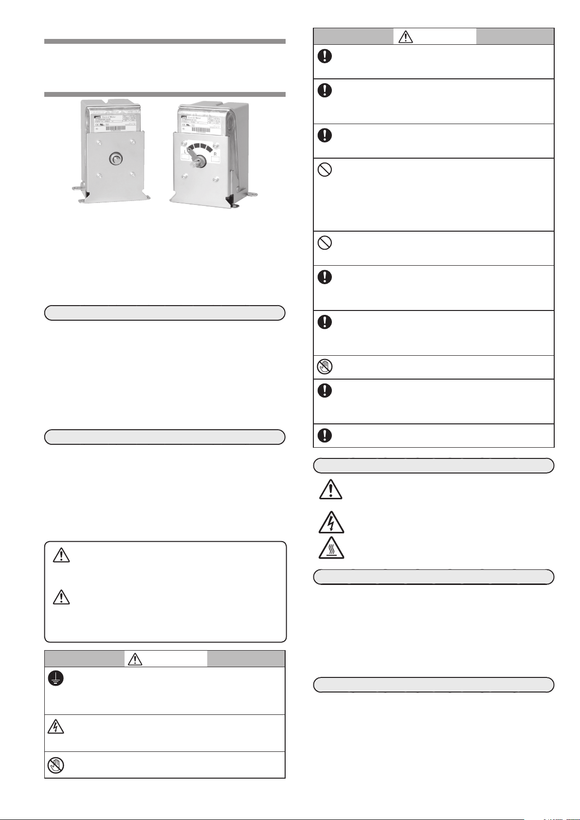
Model ECM3000
User’s Manual
Thank you for purchasing an Azbil Corporation product.
This manual contains information for ensuring the correct
use of this product. This manual should be read by those who
design and maintain equipment that uses this product.
Be sure to keep this manual nearby for handy reference.
Please read “Terms and Conditions” from the following URL
before ordering and use.
https://www.azbil.com/products/factory/order.html
NOTICE
Be sure that the user receives this manual before the product is
used.
Copying or duplicating this user’s manual in part or in whole is
forbidden. The information and specifications in this manual are
subject to change without notice.
Considerable effort has been made to ensure that this manual is
free from inaccuracies and omissions. If you should find an error or
omission, please contact the azbil Group.
In no event is Azbil Corporation liable to anyone for any indirect,
special or consequential damages as a result of using this product.
SAFETY PRECAUTIONS
Safety precautions are for ensuring safe and correct use of
this product, and for preventing injury to the operator and
other people or damage to property. You must observe these
safety precautions. Also, be sure to read and understand the
contents of this user’s manual.
If this device is used in a manner not specified by the
manufacturer, its built-in protective functions may be
impaired.
Key to symbols
l
WARNING
Warnings are indicated when mishandling this product might result in death or serious injury to the user.
CAUTION
Cautions are indicated when mishandling this product might result in minor injury to the user, or only
physical damage to this product.
WARNING
Before doing other wiring work, connect the frame
ground terminal to ground. The ground connection
should have a resistance of 100 or less. Afterwards
connect the other circuits.
Before removing, mounting, or wiring this device, be
sure to turn off the power to the device and all connected
devices. Failure to do so may cause electric shock.
Do not touch electrically charged parts such as the
power terminals. There is a risk of electric shock.
CAUTION
In order to use this product correctly, be sure to follow
this manual, the manuals for any associated devices
and equipment.
Installation, wiring, inspection, adjustment, maintenance,
etc., should be carried out only by trained and experienced technicians who have knowledge and technical
sk
ills related to this device and associated equipment.
Be sure to use this device correctly, within the ranges
specified in this user’s manual. Otherwise device failure or malfunction could result.
Avoid installing the device where it will be subject to
conditions such as the following. Otherwise device failure could result.
• Certain chemicals, corrosive gases, or salt
• High temperatures
• Prolonged vibration
• Direct sunlight
Do not stand on this device or use it as a step.
Doing so could damage the device, and if you lose your
footing you may be injured.
Wire this device properly according to indoor wiring
standards, technical standards, etc., using the types of
wire and wiring methods specified in the user’s manual.
Otherwise, device failure or malfunction could result.
The motor part of this device can reach a high temperature during operation. There is a risk of burns if the
cover is opened and the motor is touched immediately
after the power has been turned off.
While power is being supplied and during operation, do
not touch any movable part. Doing so may cause injury.
If equipment safety may be endangered by the failure
of this device, consider having a fail-safe design for the
system as a whole, with circuit breakers, duplexed controllers, and limiter; or use a redundant design.
When discarding this device, dispose of it properly as
industrial waste, following local regulations.
WARNING SYMBOLS USED FOR THE PRODUCT
To reduce the risk of an electric shock. resulting in
personal injury, and to ensure safe operation of devices, follow all safety notices in this document.
This symbol warns the user when there is a danger
of electric shock from accidental contact.
This symbol on the motor warns the user that there
is a danger of burns from accidental contact.
UNPACKING
Check the following items when removing the ECM3000 from its
package:
Name Part No. Q’ty Remarks
• Upset head bolt with captive washer
395-106-25A 4 M6 size
• label [0],[100] 83165267-001 1
• User’s Manual CP-UM-5306JE 1 This Manual
OVERVIEW
ECM3000 control motors are designed to control various types of
industrial equipment.
There are two types of strokes: a 90° stroke for burner control and
a 160° stroke for valve control using hot and cold water, steam,
etc. There are three types of control signal inputs: relay contact,
4–20mADC, and potentiometer (nominal 135Ω resistance input).
24, 100, and 200VAC models are available. Flexible 85–264VAC
powered models are also available for 4–20mADC signal input
models. The included bracket can be used for replacement of an
older Azbil Corporation motor with this one.
1
0(fully closed) and 100(fully open)
Page 2
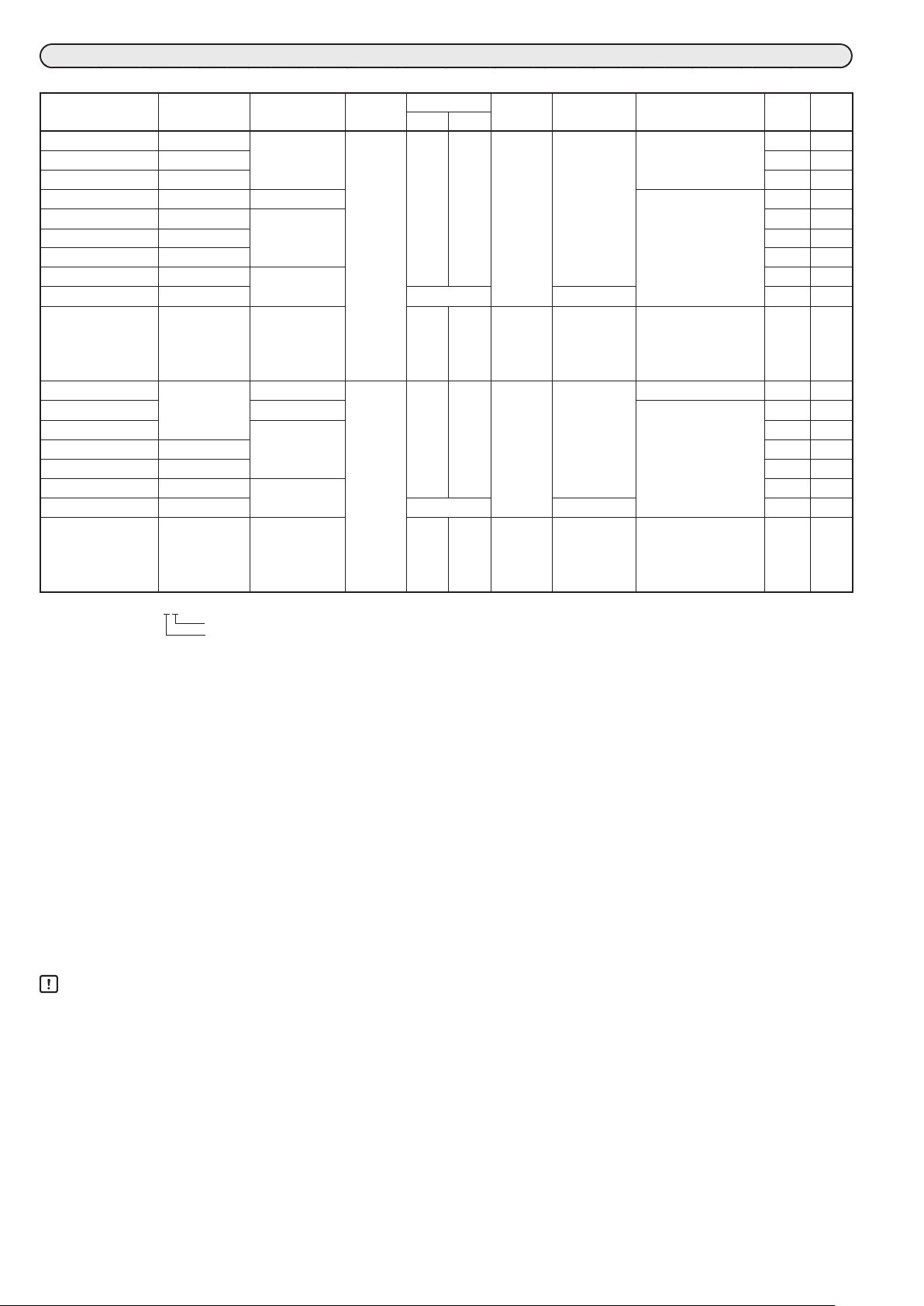
MODEL SELECTION TABLE
: Applicable —: Not applicable
Model No. Power Signal name
Rotation
angle
ECM3000D01 _ _ 24 V AC Relay contacts 90° 39 s 33 s
ECM3000D11 _ _ 100 V AC — —
ECM3000D21 _ _ 200 V AC — —
ECM3000E01 _ _ 24 V AC Potentiometer Position proportional
ECM3000F01 _ _ 24 V AC Relay contacts
ECM3000F11 _ _ 100 V AC — —
ECM3000F21 _ _ 200 V AC — —
ECM3000G01 _ _*
ECM3000G91 _ _*
2
2
24 V AC
85~264 V AC
4~20 mA DC
ECM3000F03 _ _ 24 V AC Relay contacts 20 s 16 s
ECM3000D020 _ 24 V AC Relay contacts 160° 69 s 58 s
ECM3000E020 _ Potentiometer Position proportional
ECM3000F020 _ Relay contacts
ECM3000F120 _ 100 V AC — —
ECM3000F220 _ 200 V AC — —
ECM3000G02 _ _*
ECM3000G92 _ _*
2*7
2*7
24 V AC
85~264 V AC
4~20 mA DC
ECM3000F040 _ 24 V AC Relay contacts 35 s 29 s
(Example) ECM3000D01_ _
0 (zero): not GB-compliant, C: GB-compliant
0 (zero): No options*
3
3: 4 built-in auxiliary switches (for standard model. Contact current: 100 mA to 5 A [resistive load], 100 mA to 3 A [inductive
8
load])*7 *
4: 2 built-in auxiliary switches (for standard model. Contact current: 100 mA to 5 A [resistive load], 100 mA to 3 A [in-
ductive load]) with forced open/close function*6 *
5: 4 built-in auxiliary switches (for low-current model. Contact current: 1 to 100 mA [inductive load, including inrush
current])*7*
8
6: 2 built-in auxiliary switches (for low-current model. Contact current: 1 to 100 mA [inductive load, including inrush
current]) with forced open/close function*6 *
*1. GB-compliant models are not compliant with UL or CE standards.
*2. Direct/reverse operation can be switched and zero point, span, and deadband can be adjusted. The device is adjusted at the factory with the direct opera-
tion setting. Readjustment is essential if the type of operation is switched.
*3. An extension unit can be mounted.
*4. Power consumption of the following models is 11 VA. ECM3000G014_, ECM3000G016_, ECM3000G024_, ECM3000G026_
*5. Power consumption of the following models is 15 W. ECM3000G914_, ECM3000G916_, ECM3000G924_, ECM3000G926_
*6. Selectable only for ECM3000G01_ _, ECM3000G91_ _, ECM3000G02_ _, ECM3000G92_ _.
*7. 4 built-in auxiliary switches models can not be selected.
*8. Use a class 2 power supplies with double or reinforced isolation from the MAINS power supply for the power supply and auxiliary switches.
*9. Use a limited-energy circuit (EN61010-1) with double or reinforced isolation from the MAINS power supply for the power supply and auxiliary switches.
Rotation time
50Hz 60Hz
Output
torque
12.5 N・m
39 s 14 W*
6 N・m
12.5 N・m
72 s 14 W*
6 N・m
8
8
Power
consumption
4
9 VA*
Notes UL*
ON/OFF operation
operation
5
14 VA High-speed motor
model
Position proportional
operation
4
9 VA*
ON/OFF operation
operation
5
14 VA High-speed motor
model
Position proportional
operation
1*8
CE*1*
— —
—
— —
—
9
Handling Precautions
• Use high-speed motor models at a duty ratio (operating ratio) of 40% or less.
• Do not connect the ECM3000F to a mechanical balancing relay such as the R9107A or R927C. Doing so may apply excessive voltage to
the potentiometer, resulting in device failure.
• Be sure to connect non-voltage contacts to terminals S, CONT, CW, and CCW of an ECM3000 model with forced open/close function.
In the case of the M744 and M7284, 24VAC may be applied to the S, CONT, CW, and CCW terminals.
If the ECM3000 is replaced with a forced open/close function model, do not apply 24VAC to any terminal. Doing so will damage the
circuit.
• For the ECM3000F and ECM3000D, leakage current from the snubber circuit protecting the motor drive element (relay or SSR) must
be within the following.
• 100VAC: 0.8mA (RMS) max.
• 200VAC: 0.4mA (RMS) max.
2
Page 3
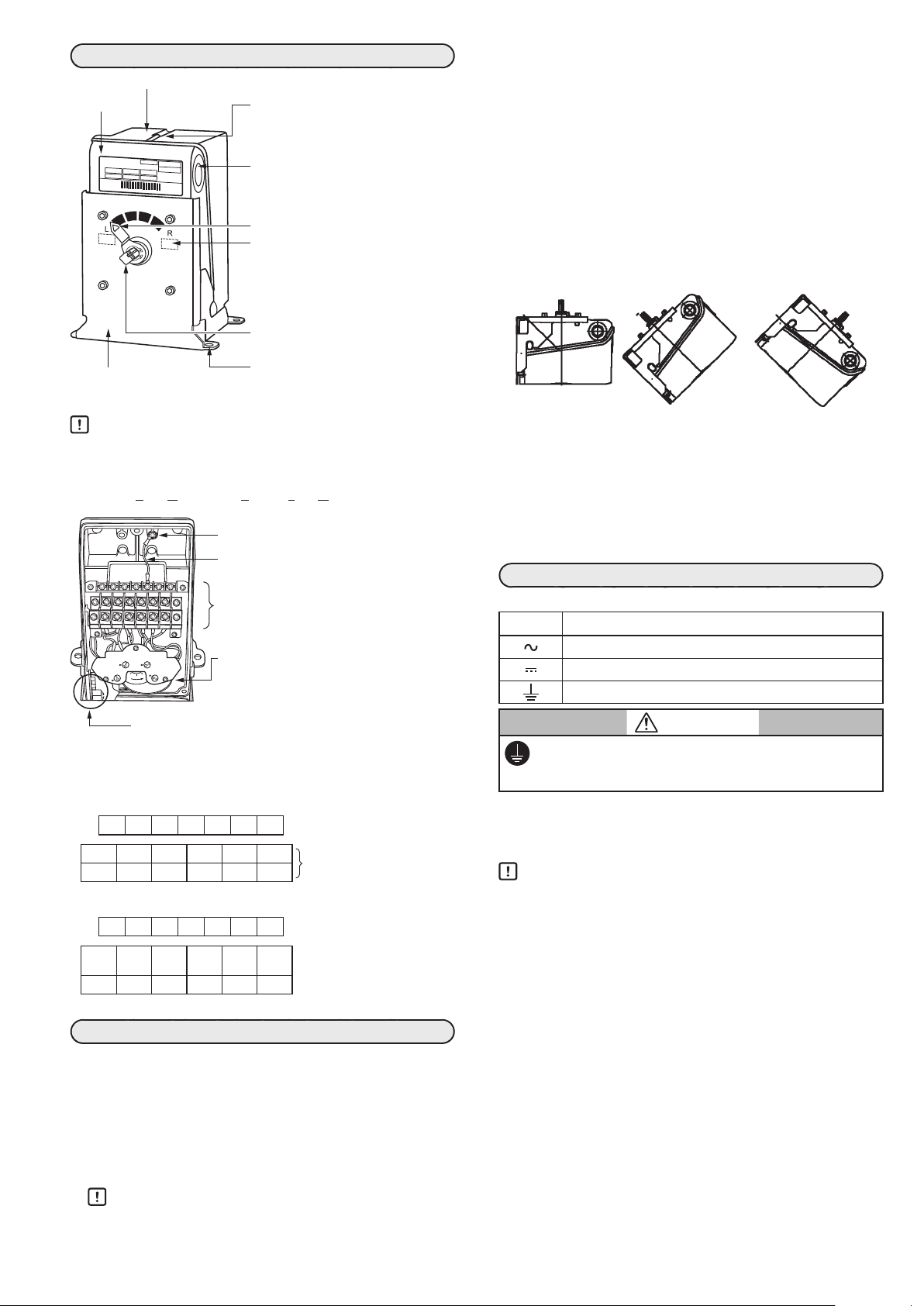
NAMES OF PARTS
Incorrect Incorrect Incorrect
Resin cover: protects the inside of the device.
Main unit
Control Motor
ECM3000E9110
*123103800150*
Bracket:
Used to mount the
control motor.
Handling Precautions
• The default setting for the output shaft is 0% opening.
• L: counterclockwise (CCW) rotation
R: clockwise (CW) rotation
CW: Clockwise CCW: Counterclockwise
7 654 3 2 1
CD
AB
0 100
Cover retaining screw:
Secures the cover. 3 screws are used.
The recommended tightening torque
is 0.8 to 1.0N·m.
Knockout hole:
Used to run the wires out.
There is one hole each on the left
and right sides.
Pointer (90° stroke models only)
Label [0],[100] (90° stroke models only):
When viewing the output shaft, “R”
indicates the valve opening direction
and “L” indicates the valve closing
direction.
Output shaft:
Moves the actuator via the linkage.
Mounting hole:
Located in the mounting bracket.
Frame ground terminal (use an M4 round
terminal lug for wiring)
Ground wire (E and G models only)
Terminal block:
Used for wiring. M3.5 screws are used.
Auxiliary switches (A, B, C, and D, or A and B):
Switches may be built into the motor depending on the model.
• When the motor is used with a control valve in an application such as fluid control, if the control valve is located
higher than the motor, water drops may enter the motor
by running along the valve.
Mounting orientation
l 90° stroke model
This model can be mounted with any desired orientation.
However, take measures to prevent water and foreign matter
from entering the output shaft.
l 160° stroke model
This device can be mounted with the output shaft horizontal or
facing downwards. To prevent water drops from entering the
device, do not mount with the output shaft facing upward.
To ensure splash-proofing
Close the cover securely so that the packing and cable are not
pinched. Make the knockout hole watertight after wiring.
• Use a waterproof connector for the cables running from the
motor. Recommended waterproof connector: refer to the
sealing item of specifications
• If a conduit is used, use a waterproof precut tube or the like
to ensure waterproofing.
WIRING
Symbols used on the device:
Symbol Meaning
AC power supply
DC signal
Functional ground terminal (not a protevtive ground terminal)
Adjustment section of 4–20mADC input models:
Direct/reverse action can be switched, and zero/span
and dead band are adjustable.
l Terminal block
For 4 built-in auxiliary switches
7 6 5 4 3 2 1
For the power supply and signals
D3 D2 D1 C3 C2 C1
B3 B2 B1 A3 A2 A1
2 built-in auxiliary switches with forced open/close function
7 6 5 4 3 2 1
S CONT CW CCW
Not
used
B3 B2 B1 A3 A2 A1
For the power supply and signals
Not
Forced open/close function
used
Auxiliary switches A and B
MOUNTING
Installation location
To install the ECM 3000, use the supplied bolt or equivalent (M6
size, with spring washer and flat washer). Use a nut (not supplied)
if necessary.
Bolt tightening torque: 4.1 to 5.2 N·m
Do not install the device in locations prohibited in the SAFETY
PRECAUTIONS section. For outdoor use, use a protective cover
or the like.
Handling Precautions
• Prevent foreign matter or moisture from entering the
device from the output shaft.
For auxiliary switches A to D
CAUTION
Make sure that the frame ground terminal is properly
grounded (100Ω max.) using at least 2mm
M4 crimp terminals with insulating sleeves.
During wiring, open a knockout hole (22mm dia.) on either side,
and pull out the cables from the hole. For wiring to the terminals,
follow the terminal label indicated on the terminal block, and be sure
to use M3.5 crimp terminals with insulating sleeves.
Handling Precautions
• To open a knockout hole, using a flat-head screwdriver, set
its tip on the outer edge of the knockout plug, and lightly
tap the screwdriver all the way around this edge until the
knockout is removed.
• Do not allow any fragments to enter the actuator when the
knockout hole is opened.
• Do not use unused terminals on the device as relay
terminals.
• Be sure to attach the cover after wiring is complete.
• Do not run the signal wires in the same conduit as power lines.
• Keep power cables at least 50cm away from signal cables.
• If the power and signal cables must run together in the
same conduit, use JCS4364-compliant instrument cable
for signals.
• Use the appropriate supply voltage according to the
model No.
• Be sure to install a circuit breaker (8A max) for the power
source.
• During motor operation, in order to stop hunting (which
causes the controller’s internal relay to turn ON and OFF
excessively), change the parameters of the controller.
For example, set the derivative time (D) to 0 seconds, set
a wider dead band, etc.
If the internal relay operates excessively, the life of the
motor or the host controller relay will be shortened.
3
2
wire and
Page 4

l Cables
F.G .
F. G .
A1 A2 A3
COM
L
CCW CW CONT S
CCW CW CONT S
CCW CW CONT S
XO
(resistance input of nominal 135 Ω)
0 % when XC is open
Except for 24 V AC models, use a power cable rated at 600 V or
more and 70 °C or higher.
For 24 V AC models, use a power cable rated at 60 V or more
and 70 °C or higher.
The auxiliary switch cable should be rated at a voltage sufficient
for the operating voltage and rated at 70 °C or higher.
For other signal lines, use cables rated at 60 V or more and
70 °C or higher.
l Relay contact input (ECM3000D and ECM3000F)
M
l Auxiliary switch (up to 4)
L: counterclockwise (CCW) rotation
R: clockwise (CW) rotation
R
Note: The internal connections of switches B, C,
and D are the same as those of switch A.
Models with forced open/close function
have only auxiliary switches A and B.
l Forced open/close input
(a) Forced fully closed (b) Forced fully open (c) Automatic operation
1 2
L R G Y T
L: counterclockwise (CCW) rotation
R: clockwise (CW) rotation
CW: Clockwise CCW: Counterclockwise
*1. The supply voltage varies depending on the model.
MODEL SELECTION TABLE (page 2 )
*2. Terminals 4–6 of the ECM3000D are not used.
3 4 5 6 7
*2 *2 *2
Not used
*1
Handling Precautions
• The default setting for the output shaft is 0% opening.
l Potentiometer input (135) (ECM3000E)
1 2
24 V AC
L: counterclockwise (CCW) rotation
R: clockwise (CW) rotation
* For details on TY9000, etc., contact the azbil Group.
l 4–20mA input (ECM3000G)
3 4 5 6 7
1 2
3 4 5 6 7
*
W
B R
*
RL
+ −
4–20 mA DC
Not used
Not used
Handling Precautions
• Before shipment, terminals CONT and S are connected.
Disconnect these terminals if operation with the valve
forced fully open (or closed) is desired.
• Only one of terminals CCW, CW, and CONT can be connected to terminal S. Multiple terminals cannot be connected to terminal S.
• Be sure to connect non-voltage contacts to terminal S,
CONT, CW, or CCW of an ECM3000 model with a forced
open/close function. If 24VAC is applied, the circuits will
fail.
• If the same signal is input to multiple control motors that
are connected in parallel, faulty operation may result.
The same contact signal cannot synchronize multiple
ECM3000 motors.
l If the ECM3000E is used to fully open/close the valve
W
B
R
Azbil Corporation's
L91 pressure regulator
Switch for
full open
Switch for
full close
XC
4
5
6
1
2
W
B
R
T
1
T
2
ECM3000E
Note
• The 4–20mA input circuit is isolated from the power circuit
inside the device.
Handling Precautions
• During motor operation, in order to stop hunting (which
causes the controller’s internal relay to turn ON and OFF
excessively), change the parameters of the controller. For
example, set the derivative time (D) to 0 seconds, set a
wider dead band, etc.
If the internal relay operates excessively, the life of the
motor or the host controller relay will be shortened.
If frequent operation cannot be avoided, install an auxiliary
relay between the motor and controller.
• The feedback potentiometer of the ECM3000F is a combination resistor consisting of two different resistors connected in parallel.
Accordingly, the angle of rotation of the ECM3000F is proportional not to the resistance of the feedback potentiometer but to the voltage ratio between the potentiometer
terminals (T–G voltage or Y–G voltage).
The resistance of the feedback potentiometer cannot be
used to measure the angle of the motor rotation.
* The supply voltage varies depending on the model.
MODEL SELECTION TABLE (page 2 )
XO XC
100 % when XO is open
Note: Recommended contact rating for XO and XC
Material: Gold plating
Rated voltage: 15V DC min.
Rated current: 100mA
Transformer
Power supply
4
Page 5

INSPECTION AND MAINTENANCE
Between terminals 1 and 2
Approx. 2 % differential
Between terminals 1 and 3
Opening
NC
Auxiliary switch: Sw.D
Terminal block
Terminal block A
Setting dial
Inspection Method
Item Frequency Inspection method
Visual
inspection
Operation
state
Daily
inspection
Maintenance method
Cleaning: If the module is dirty, wipe it with a soft, dry cloth. Do
not use a detergent or an organic solvent like thinner or benzene.
Check the motor operation visually every six months. If a problem is found, take corrective actions.
• The motor does
not work.
• The motor rotation
stops halfway.
• Auxiliary switches
do not work.*
• The feedback potentiometer does
not work.*
• Decreased control
sensitivity.
• Deceased motor
torque.
*1. For models with auxiliary switch
*2. For models with feedback potentiometer
6 months • Check for loose screws.
• Check for damage to the motor.
6 months • Check for unusual noise or vibration.
• Check that the motor operation is normal.
As needed • Check for unusual noise or vibration.
• Check that the motor operation is normal.
• Check hunting.
Problem Check item Corrective action
• Wiring status and
disconnection.
• Supply power voltage.
• Check for loose terminal
screws.
• Check the auxiliary
1
switch cam.
• Wiring status and
disconnection.
• Check the resistance.
2
• Wiring status and
disconnection.
• Check for loose terminal
screws.
• Wiring status and
disconnection.
• Check for loose terminal
screws.
• Supply power voltage.
• Check the wiring.
• Check the supply
power voltage.
• Tighten terminal
screws.
• Set it up again.
• Check the wiring.
• Set it up again.
• Check the wiring.
• Tighten terminal
screws.
• Check the wiring.
• Tighten terminal
screws.
• Check the supply
power voltage.
l How to set the operating point
(1) Operate the motor electrically until the output shaft travels
to the desired angle that turns on the switch. Then, align
the arrow on the setting dial with the
mark using a flat-
head screwdriver.
(2) Operate the motor electrically to rotate the output shaft
near the set travel position, and check that the switch
works normally.
The figure below shows an example of setting at 50% opening.
A1
A2
A3
B1
B2
B3
C1
C2
C3
D1
D2
D3
Terminal block B
COM
COM
COM
COM
Auxiliary switch: Sw.A
(variable 5–95 %)
NO
NC
Auxiliary switch: Sw.B
(variable 5–95 %)
NO
NC
Auxiliary switch: Sw.C
(variable 5–95 %)
NO
NC
(variable 5–95 %)
NO
Adjustment
l Operating point
An auxiliary switch can turn on if the arrow on the setting dial
(A, B, C, or D) is aligned with the
The operating point can be set in a range of 5–95% opening.
The repeatability is within ±3%.
The differential is approximately 2%.
After the settings are changed, make sure that the switch operates before the motor reaches the fully-open and fully-closed
positions.
l Operation type
If the actual opening is greater than the set opening, connection between terminals 1 and 2 (Common–NO) will be electrically continuous, but connection between terminals 1 and 3
(Common–NC) will not be.
The figure below shows an example in which, at 50% opening,
connection between terminals 1 and 2 is ON while connection
between terminals 1 and 3 is OFF.
AUXILIARY SWITCH OPTIONAL
mark.
OFF ON
ON OFF
10 %
50 %
(exam ple)
90 %
Note
• Use a 6mm flat-head screwdriver for the slotted-head screws
(JIS B 4609).
5
Page 6

Installation and removal
Screws
terminal block
(7)
Base kit
l Installation
(1) Turn OFF the power.
(2) Loosen the 3 screws and remove the cover. Keep the re-
moved parts in a safe place.
l Removal
(1) Remove the 2 screws.
(2) Remove the terminal block. The bracket is combined with
the terminal block.
(3) Press and hold the release button.
(4) Turn the auxiliary switch unit clockwise.
(5) Remove the unit by pulling it up.
(1)
(2)
(5)
(3)
(1)
(3) Rotate part B of the chassis upward and remove it. Fold
part A of the terminal block outside and remove it.
Part B of the
chassis
Part A of the
(4) Insert the shaft of the auxiliary switch into the actuator
shaft. (The triangular arrow on the 0–100 dial should be
positioned within the scale.)
(5) Turn the auxiliary switch unit counterclockwise until it
clicks.
(6) Align the holes on the terminal block bracket with the
holes on the chassis.
(7) Insert and tighten the 2 screws.
(4)
MOUNTING ON A BUTTERFLY VALVE V51E
If this device is mounted on the V51E, install the base kit
(83165292-001, sold separately) between the V51E and the device.
Device
(5)
(4)
(6)
(6)
(7)
V51E
6
Page 7

G Y T
R: 180 Ω
ECM3000F
350
0.9
Resistance between terminals G and T (Ω)
Voltage between terminals G and T (V)
Resistance
Voltage
SPECIFICATIONS
Specifications
Item Specifications
Operation mode (fixed
by the model)
Input signal Relay contact, 4–20mADC, potentiometer
Feedback
potentiometer
Input impedance (with
4–20mADC input)
Angle of rotation
(fixed by the model)
Rotation
time
90° stroke
model
160° stroke
model
Output torque 12.5N·m (high-speed motor: 6N·m)
Supply power voltage
(fixed by the model)
Power consumption
(during operation)
Standard operating
conditions
Ambient temperature −20 to +60°C
Ambient humidity 5–95%RH (without condensation)
Vibration resistance 4.9m/s
Insulation resistance 5M min. with a 500VDC megger between
Dielectric strength 500VAC for 60 s (24VAC models), 1200VAC
Default positions of
auxiliary switches
Forced open/close
input
Sealing Equivalent to IP54 when using the following
Material Case: Die-cast aluminum
Installation location Indoors
Altitude 2000 m max.
Pollution degree 3
Mass Approx. 3kg
ON-OFF or position proportioning
Reference resistance for selection: 135 (combination resistor
*1
)
Max. applied voltage: 5VDC
125max. (at 20mA) (45 of signal reception
resistor + resistance of overcurrent protection
circuit)
90° or 160°
39/33 s Relay contact, 50/60Hz without load
39 s Supply power: 85–264VAC, 50/60Hz
without load
20/16 s Relay contact, 50/60Hz, without load,
high-speed motor model
69/58 s Relay contact, 50/60Hz without load
72 s Supply power: 85–264VAC, no load,
50/60Hz without load
35/29 s Relay contact, 50/60Hz, without load,
high-speed motor
24VAC ±15%, 50/60Hz
100VAC ±10%, 50/60Hz
200VAC ±10%, 50/60Hz
85–264VAC, 50/60 Hz
MODEL SELECTION TABLE (page 2 )
23±2°C, 50 ±10%RH
2
housing and power supply, signal terminals, or
forced open/close input terminals
20M min. with a 500VDC megger between
housing and auxiliary switches
for 60s (100VAC models), 1500VAC for 60s
(200VAC and 85–264VAC models) between
housing and power & signal terminals
1500VAC for 60s between housing and auxiliary switch terminals
500VAC for 60s (24VAC models), 1200VAC
for 60s (100VAC models), 1500VAC for 60s
(200VAC and 85–264VAC models) between
housing and power & forced open/close input
terminals
A and C: at 9° ±5°
*2
B and D: at 81°±5°
Non-voltage contact
Contact rating: 15VDCmin., 100mAmin,
Contact resistance: 10Ωmax. (at 1mADC)
waterproof connector.
However, not UL-certified.
Model no. : 83104346-003
Lock nut tightening torque : 1.0 Nm
Tightening cap (cable) tightening torque : 1.5 Nm
Applicable cable diameter : 7 to 9 mm
Cover: Glass-containing polycarbonate resin
Bracket: Steel
Item Specifications
Terminal screw tightening torque and wire
size
For power and signal terminals:
0.8 N·m
14 to 18 AWG (0.75 to 2.0 mm
For auxiliary switches and forced open/close
function:
0.8 to 1.2 N·m
Standards
compliance
14 to 18 AWG (0.75 to 2.0 mm
*3
CE: EN 55011, EN 61000-6-2 *
UL: UL 61010-1
4
GB: GB 30439.8
*1. Feedback potentiometer output specifications
The feedback potentiometer of the ECM3000F has the following equivalent circuit. (See the diagram of parallel resistors below.)
In the controller, the resistance of the feedback potentiometer is converted to voltage, which indicates the motor opening.
In other words, the angle of rotation is not calculated directly from
the resistance of the potentiometer. But if a combination resistor
(1k+180) is used, the resistance can be close to 135, which has
been conventionally used in the industry.
The following are Azbil Corporation’s controllers compatible with
this device: SDC35/36, SDC45/46, the SDC40 series, DMC10, Network
Instrumentation Modules, RN748.
For other products, please contact the azbil Group.
4 5 6
Counterclockwise
(close)
Clockwise
(open)
P
R
P: 1 kΩ
Note
• In old models, such as the M904, because the feedback
potentiometer uses a single resistor, if the resistance of the
potentiometer is measured (between terminals G and T)
with a continuity tester, the motor opening can be deduced.
However, the output part of the feedback potentiometer of this
device consists of multiple resistors. Thus, unlike old models,
its resistance is not proportional to the motor opening.
The controller calculates the motor opening from the voltage
between terminals G and T.
The voltage between terminals G and T is linear to the motor
opening, but if the resistance between these terminals is measured, as was possible for older models, the result will not be
linear to the motor opening. Instead, the relationship can be
graphed as a parabola, as shown below.
300
250
200
150
100
50
0
0 10 20 30 40 50 60 70 80 90 100
Opening (%)
*2. For 90° stroke models with auxiliary switches
*3. Varies depending on the model.
MODEL SELECTION TABLE (page 2 )
*4. During EMC testing, the reading may fluctuate by ±5%FS
0.8
0.7
0.6
0.5
0.4
0.3
0.2
0.1
0
2
)
2
)
7
Page 8
Optional parts (sold separately)
position
10°
Output shaft
Closed position
Open position
160°
Name Model No.
Crank arm N-3128
Damper arm J-26026G-ARM
Ball joint J-27518-JOINT
Valve linkage
Damper linkage Q605A/D/E
V51 base kit 83165292-001
Waterproof connector 83104346-003
24 V AC power transformer AT72-J1
Extension
*2
unit
*1. Can be attached to 160° stroke models.
*2.
Only one type of extension unit can be mounted on the model without
internal auxiliary switch.
*3. For compliance with GB standards, use this model.
Handling Precautions
• The output of the auxiliary potentiometer cannot be connected to an M904E Modutrol motor and to an ECM3000E
motor. Use the potentiometer for output to an external
valve-opening indicator or the like.
l Auxiliary switch
Auxiliary switches
Contact rating Standard model.: 250 V AC, 100 mA to 5 A
Service life Standard model: 50,000 cycles or more.
Default positions A and C: at 9°±5°
Setting range 5–95% opening
Terminals (4 or 2) 1 Common
* Models with forced open/close function have only auxiliary switches
A and B.
l Auxiliary potentiometer
Total resistance 1k ±10%
Accuracy ±8%FS
Hysteresis ±5%FS
Terminal Y voltage change in
relation to the applied voltage
Max. applied voltage 5VDC
*1
4 built-in auxiliary
switches
Q455C/D
83174065-002
(Contact current: 100 mA to 5 A [resistive
load], 100 mA to 3 A [inductive load])
83174065-102
(Contact current: 1 to 100 mA [inductive
load, including inrush current])
83174065-003
*3
(Contact current: 100 mA to 5 A [resistive
load], 100 mA to 3 A [inductive load])
83174065-103
*3
(Contact current: 1 to 100 mA [inductive
load, including inrush current])
Auxiliary potentiom-
83165272-001
eter for 90° stroke
Auxiliary potentiom-
83165272-002
eter for 160° stroke
Item Specifications
*
4 (or 2)
(resistive load), 100 mA to 3
A (inductive load)
Low-current model.: 250 V AC, 1 to 100 mA
(inductive load, including
inrush current)
Note: See Model Selection Table notes *
Low-current model: 200,000 cycles or more.
Note: Service life figures assume a resistive load.
B and D: at 81°±5°
2 NO (Normally Open)
3 NC (Normally Closed)
Continuous change between
14±6% (0% opening) and 86±6%
(100% opening)
8
and *9.
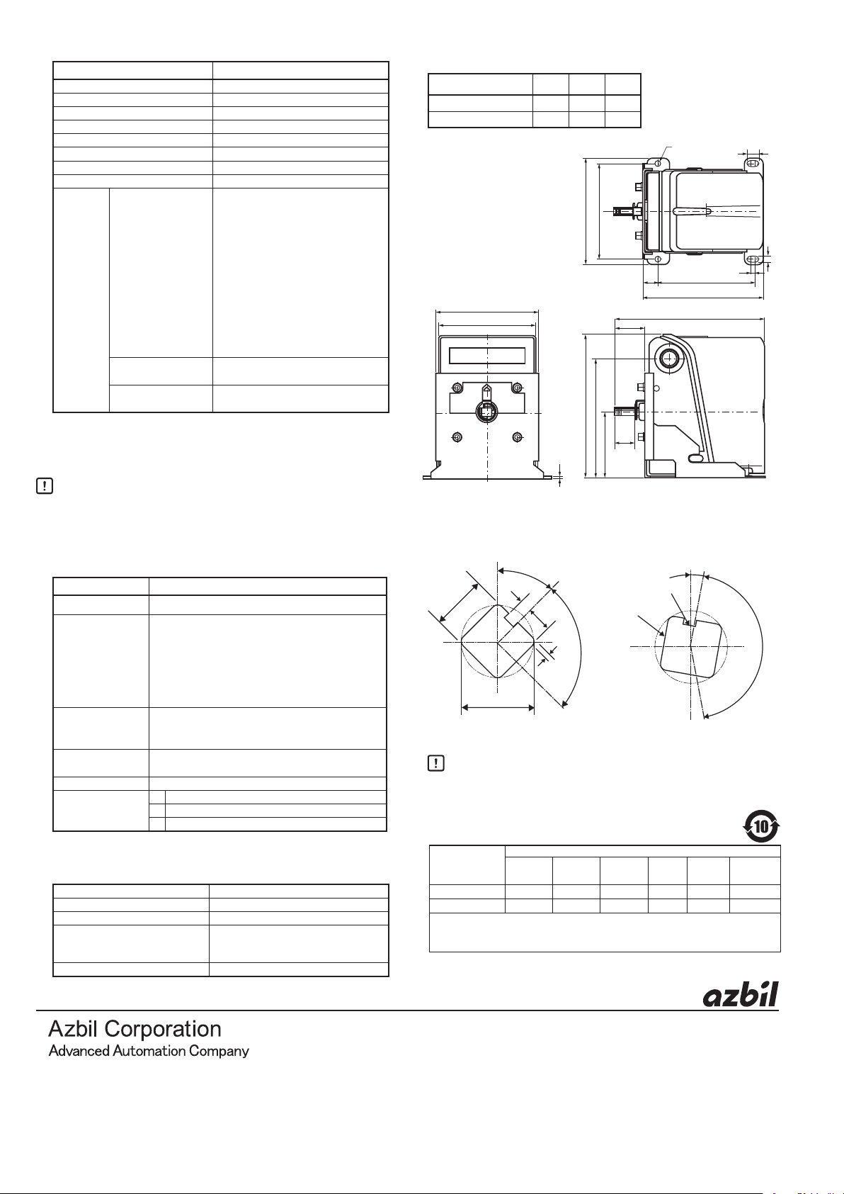
External dimensions
Unit: mm
Angle of rotation A B C
90° stroke model 32.5 161.6 22
160° stroke model 20.5 149.6 12
7 ϕ
124
139
111
104
2
185
154
A
C*
85
* C is the length of the output shaft (9.5mm square).
l 0% opening position of the output shaft (when viewing
the output shaft)
45°
−0
−0.05
9.5 square
2.4±0.1
0
11.8 dia.
−0.1
4.5±0.1
Closed
position
1.2±0.1
Open
Key groove
90°
90° stroke model 160° stroke model
Handling Precautions
• The length of the output shaft varies depending on the
model. Only 90° stroke models have a pointer.
基于SJ/T11364-2014 「电子电气产品有害物质限制使用标识要求」的表示式样
部件名称
电路板组件 × ○ ○ ○ ○ ○
本体 × ○ ○ ○ ○ ○
本表格依据SJ/T 11364 的规定编制。
○ : 表示该有害物质在该部件所有均质材料中的含量均在GB/T 26572规定的限量要求以下。
× : 表示该有害物质至少在该部件的某一均质材料中的含量超出GB/T 26572规定的限量要求。
产品中有害物质的名称及含量
铅
(Pb)
汞
(Hg)镉(Cd)
有害物质
六价铬
(Cr(VI))
104.516.5
128.5
B
多溴联苯
(PBB)
12
5
多溴二苯醚
(PBDE)
7
1-12-2 Kawana, Fujisawa
Kanagawa 251-8522 Japan
: https://www.azbil.com
URL
© 2003–2019 Azbil Corporation. All Rights Reserved.
Specifications are subject to change without notice.
1st edition: Dec. 2003 (E)
8
10th edition: July 2019 (V)
(11)
 Loading...