

Page 1
DCP551 Mark
ΙΙ
DIGITRONIK
Digital Control Programmer
User's Manual
No. CP-SP-1032E
Thank you for purchasing an Azbil
Corporation product.
This manual contains information for
ensuring the correct use of this
product.
It also provides necessary information
for installation, maintenance, and
troubleshooting.
This manual should be read by those
who design and maintain equipment
that uses this product. Be sure to
keep this manual nearby for handy
reference.
(Not for use in Japan)
Page 2

Please, read the ‘Terms and Conditions’ from following URL before
the order and use.
http://www.azbil.com/products/bi/order.html
The DIGITRONIKTMis a trademark of Azbil Corporation in Japan.
NOTICE
© 1998-2016 Azbil Corporation All Rights Reserved.
Be sure that the user receives this manual before the product is used.
Copying or duplicating this user’s manual in part or in whole is forbidden. The information and specifications in this manual are subject to
change without notice.
Considerable effort has been made to ensure that this manual is free
from inaccuracies and omissions. If you should find an error or omission, please contact Azbil Corporation.
In no event is Azbil Corporation liable to anyone for any indirect, special
or consequential damages as a result of using this product.
Page 3

i
To reduce risk of electrical shock which could cause personal injury, follow all safety
notices in this documentation.
This symbol warns the user of a potential shock hazard where hazardous live voltages
may be accessible.
• If the equipment is used in a manner not specified by the manufacturer, the protection
protection provided by the equipment must be impaired.
• Do not replace any component (or part) not explicitly specified as replaceable by your
supplier.
• All wiring must be in accordance with local norms and carried out by authorized experienced
personnel.
• The ground terminal must be connected before any other wiring (and disconnect last).
•A switch in the main supply is required near the equipment.
• Mains power supply wiring requires a (T) 0.5A, 250V fuse(s).
DCP551 models sold in September 2013 or later have a built-in fuse.
Over-voltage:Category II (IEC60364-4-443, IEC60664-1)
Specification of common mode voltage:The common mode voltages of all I/O except for main
supply are less than 33Vrms, 46.7V peak and 70Vdc.
EQUIPMENT RA
TINGS
Supply voltages 85 to 264V AC
Frequency 50/60Hz
Power or current ratings 40VA maximum
EQUIPMENT CONDITIONS
Do not operate the instrument in the presence of flammable liquids or vapors. Operation of any
electrical instrument in such an environment constitutes a safety hazard.
Temperature: 0 to 50˚C
Humidity: 10 to 90%RH
Vibration: 2m/s
2
Over-voltage category: Category II (IEC60364-4-443, IEC60664-1)
Pollution degree: Pollution degree 2
Installation location: Indoors
Altitude: 2000m or less
EQUIPMENT INST
ALLATION
The controller must be mounted into a panel to limit operator access to the rear terminals.
STANDARDS COMPLIANCE
EN61010-1, EN61326-1 (For use in industrial locations)
During EMC testing, the reading or output may fluctuate by ±10 %FS.
However, PV reading is within ±30 %FS.
CAUTION
Danger of explosion if battery is incorrectly replaced.
Replace only with the same or equivalent type recommended by the manufacturer.
Dispose of used batteries according to the manufacturer’s instructions.
SAFETY REQUIREMENTS
Page 4
■ About Icons
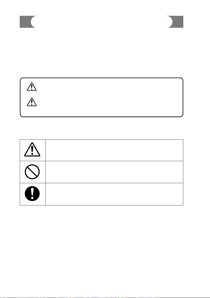
The safety precautions described in this manual are indicated by various icons.
Please be sure you read and understand the icons and their meanings described
below before reading the rest of the manual.
Safety precautions are intended to ensure the safe and correct use of this product, to prevent injury to the operator and others, and to prevent damage to property. Be sure to observe these safety precautions.
■ Examples
ii
SAFETY PRECAUTIONS
WARNING
Warnings are indicated when mishandling this
product might result in death or serious injury.
CAUTION
Cautions are indicated when mishandling this
product might result in minor injury to the user, or
only physical damage to the product.
Use caution when handling the product.
The indicated action is prohibited.
Be sure to follow the indicated instructions.
Page 5
iii
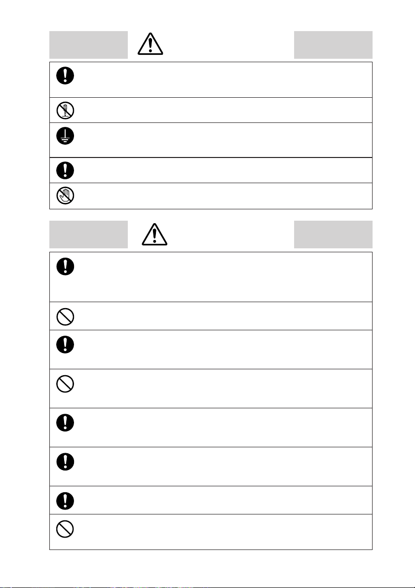
WARNING
CAUTION
Be sure to follow the operating requirements (regarding temperature,
humidity, voltage, vibration, shock, mounting direction, atmosphere, etc.) as
stated in the specifications of the controller.
Failure to heed this caution may lead to fire or malfunction.
Do not block ventilation openings.
Failure to heed this caution may lead to fire or malfunction.
Make sure that wire scraps, chips or water do not enter inside the case of the
controller.
Failure to heed this caution may lead to fire or malfunction.
Do not use pointed objects such as mechanical pencils or pins to press the
keys on the controller.
This may result in malfunction.
Connect the controller as specified using designated cables and connection
procedures.
Failure to heed this caution may lead to electric shock, fire or malfunction.
Current applied to current input terminals (55), (56) and (58), (59) must meet
the specified range.
Failure to heed this caution may lead to fire or equipment breakdown.
All terminal screws shall be tightened to specified torque.
Improperly tightened screws may lead to electric shock or fire.
Do not use unused terminals on the instrument as relay terminals for other
equipment. Failure to heed this caution may lead to electric shock, fire or
equipment breakdown.
Before removing, mounting, or wiring this module, be sure to turn off the
power to the module and all connected devices.
Doing so may result in an electric shock.
Do not disassemble the controller as this could lead to electric shock
or malfunction.
Connect the FG terminal to ground with a ground resistance of maximum
100Ω before connecting other equipment and external control circuits.
Failure to do so may cause electric shock or fire.
Be sure to turn off the power supply when you connect the controller.
Failure to do so may lead to electric shock or fire.
Do not touch a live part such as a power terminal.
This may result in electric shock.
Page 6
iv
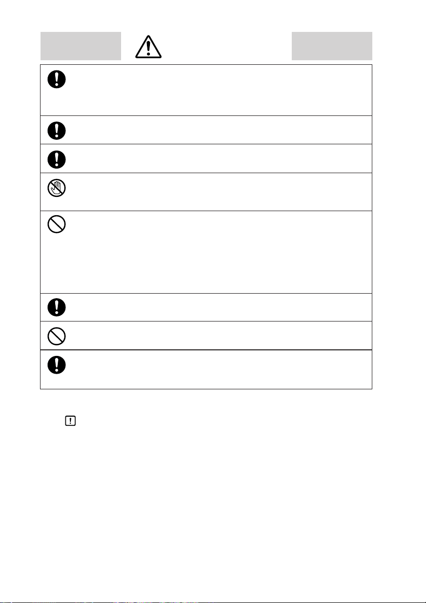
CAUTION
Attaching the terminal covers after completing the controller connections is
highly recommended.
Failure to heed this caution may lead to fire or malfunction. (Terminal covers
are supplied with the controller.)
If there is a risk of a power surge caused by lightning, use a surge protector
to prevent fire or device failure.
Be sure to turn off the power supply when you are replacing the batteries.
Failure to heed this warning may lead to electric shock.
Be sure not to touch internal components during battery replacement or just
after the power has been turned.
This may result in burn injuries.
•
Make sure that the batteries are inserted with the plus (+) and minus (–)
poles correctly oriented.
•
Do not use damaged batteries or batteries that leak.
•
Do not throw batteries into a fire, recharge, disassemble or expose them to
heat.
•
Store batteries in a cool, dry place.
Failure to heed these cautions may result in burns or battery leakage.
Batteries should be kept out of reach of children, since they may swallow
them. Should a child swallow a battery, contact a doctor immediately.
When disposing of used batteries at the user site, observe local bylaws.
Before you touch internal components, be sure to discharge any static
electricity on your body by touching a metal ground connector.
Failure to heed this caution may lead to equipment damage.
Handling Precautions
After turning on the DCP551 mark ΙΙ, leave it for at least 10 seconds to let it
stabilize before you start using it.
Page 7

Organization of This User's Manual
v
This manual is organized as follows.
Chapter 1. PRODUCT OUTLINE
This chapter explains the use and features of the DCP551 and provides the basic
function block and product model numbers.
Chapter 2. NAMES AND FUNCTIONS OF PARTS
This chapter gives the names and functions of parts of the DCP551, and input
type and range number.
Chapter 3. INSTALLATION AND MOUNTINGS
This chapter describes the procedure for mounting the DCP551 onto an operation
console.
We strongly urge persons responsible for device design on the DCP551 read this
chapter.
Chapter 4. WIRING
This chapter describes the wiring procedure and precautions required for installing
the DCP551.
We strongly urge persons responsible for device design and wiring of the
DCP551 read this chapter.
Chapter 5. FUNCTIONS
This chapter explains detailed functions of the DCP551.
We strongly urge persons responsible for control design on the DCP551 read this
chapter.
Chapter 6. OPERATION
This chapter gives the selections of the basic display, program selection, operation,
and other information.
We strongly urge persons responsible for device design and operation on the
DCP551 read this chapter.
Chapter 7. PARAMETER SETUP
This chapter describes the parameter setting method of the DCP551 and the
meaning of settings.
Chapter 8. PROGRAM SETUP
This chapter describes the program setting method of the DCP551 and the
meaning of settings.
Chapter 9. MEMORY CARD OPERATION
This chapter describes how to use memory cards.
NOTE
This chapter is not applicable to the DCP551B***** model.
Chapter 10. MAINTENANCE AND TROUBLESHOOTING
This chapter describes checkpoints and countermeasures when the DCP551 is not
operating normally.
Chapter 11. DISPOSAL
This chapter describes the disposal of the DCP551.
Chapter 12. SPECIFICATIONS
This chapter gives the general specifications, performance specifications and the
external dimensions of the DCP551.
Page 8

vi
SAFETY REQUIREMENTS
SAFETY PRECAUTIONS
Organization of This User's Manual
Conventions Used in This Manual
Chapter 1. PRODUCT OUTLINE
1-1 Features •••••••••••••••••••••••••••••••••••••••••••••••••••••••••••••••••••1-1
1-2 Basic Function Block Diagram•••••••••••••••••••••••••••••••••••••••••••••1-2
1-3 Data Configuration Overview ••••••••••••••••••••••••••••••••••••••••••••••1-3
1-4 System Configuration •••••••••••••••••••••••••••••••••••••••••••••••••••••1-4
■ CPL communications network-based configuration •••••••••••••••••••1-4
1-5 Model Number •••••••••••••••••••••••••••••••••••••••••••••••••••••••••••••1-5
Chapter 2. NAMES AND FUNCTIONS OF PARTS
2-1 Structure•••••••••••••••••••••••••••••••••••••••••••••••••••••••••••••••••••2-1
2-2 Console••••••••••••••••••••••••••••••••••••••••••••••••••••••••••••••••••••2-2
■ Basic display status •••••••••••••••••••••••••••••••••••••••••••••••••••2-2
■ Display •••••••••••••••••••••••••••••••••••••••••••••••••••••••••••••••••2-2
■ Key pad ••••••••••••••••••••••••••••••••••••••••••••••••••••••••••••••••2-4
■ Key chord functions •••••••••••••••••••••••••••••••••••••••••••••••••••2-6
■ Loader jack ••••••••••••••••••••••••••••••••••••••••••••••••••••••••••••2-7
2-3 Input Type and Range Number ••••••••••••••••••••••••••••••••••••••••••••2-8
■ Input •••••••••••••••••••••••••••••••••••••••••••••••••••••••••••••••••••2-8
Chapter 3. INSTALLATION AND MOUNTING
3-1 Before Installation •••••••••••••••••••••••••••••••••••••••••••••••••••••••••3-1
■ Mounting position••••••••••••••••••••••••••••••••••••••••••••••••••••••3-1
■ Sources of electrical interference and countermeasures
••••••••••••••3-2
3-2 Installation
•••••••••••••••••••••••••••••••••••••••••••••••••••••••••••••••••3-3
■ Panel cutout dimension ••••••••••••••••••••••••••••••••••••••••••••••••3-3
■ Installation procedures
••••••••••••••••••••••••••••••••••••••••••••••••3-4
Chapter 4. WIRING
4-1 Precautions on Wiring •••••••••••••••••••••••••••••••••••••••••••••••••••••4-1
4-2 Recommended Cables•••••••••••••••••••••••••••••••••••••••••••••••••••••4-3
4-3 Making Terminal Connections •••••••••••••••••••••••••••••••••••••••••••••4-4
4-4 Terminal Array
•••••••••••••••••••••••••••••••••••••••••••••••••••••••••••••4-5
4-5 Power Supply and Grounding
•••••••••••••••••••••••••••••••••••••••••••••4-6
Contents
Page 9

vii
■ Power supply ••••••••••••••••••••••••••••••••••••••••••••••••••••••••••4-6
■ Grounding •••••••••••••••••••••••••••••••••••••••••••••••••••••••••••••4-6
4-6 PV Input (Analog Input) Connection •••••••••••••••••••••••••••••••••••••••4-7
■ PV input CH1 connection ••••••••••••••••••••••••••••••••••••••••••••••4-7
■ PV input CH2 connection ••••••••••••••••••••••••••••••••••••••••••••••4-7
4-7 Control Output Connection ••••••••••••••••••••••••••••••••••••••••••••••••4-9
■ Current output (5G, 5S) ••••••••••••••••••••••••••••••••••••••••••••••••4-9
■ Voltage output (6D) ••••••••••••••••••••••••••••••••••••••••••••••••••••4-9
■ Open collector output (8D) •••••••••••••••••••••••••••••••••••••••••••••4-9
4-8 Auxiliary Output (Output CH1, CH2) Connection •••••••••••••••••••••••••4-10
■ Auxiliary output CH1 connection •••••••••••••••••••••••••••••••••••••4-10
■ Auxiliary output CH2 connection •••••••••••••••••••••••••••••••••••••4-10
4-9 Event Output (Open Collector Output) Connection•••••••••••••••••••••••4-11
4-10 External Switch Input Connection ••••••••••••••••••••••••••••••••••••••••4-12
4-11 Communication Connection••••••••••••••••••••••••••••••••••••••••••••••4-13
■ RS-485 connection••••••••••••••••••••••••••••••••••••••••••••••••••••4-13
■ RS-232C connection ••••••••••••••••••••••••••••••••••••••••••••••••••4-16
■ Connection to ST221 •••••••••••••••••••••••••••••••••••••••••••••••••4-17
4-12 Isolation During Input/Output•••••••••••••••••••••••••••••••••••••••••••••4-18
Chapter 5. FUNCTIONS
5-1 Data••••••••••••••••••••••••••••••••••••••••••••••••••••••••••••••••••••••••5-1
■ Data types••••••••••••••••••••••••••••••••••••••••••••••••••••••••••••••5-1
5-2 Program Pattern •••••••••••••••••••••••••••••••••••••••••••••••••••••••••••5-2
■ Pattern •••••••••••••••••••••••••••••••••••••••••••••••••••••••••••••••••5-2
■ Events •••••••••••••••••••••••••••••••••••••••••••••••••••••••••••••••••5-5
■ PID group selection •••••••••••••••••••••••••••••••••••••••••••••••••••5-16
■ Selection of output limiter group •••••••••••••••••••••••••••••••••••••5-16
■ G.SOAK (Guarantee soak) ••••••••••••••••••••••••••••••••••••••••••• 5-17
■ PV shift •••••••••••••••••••••••••••••••••••••••••••••••••••••••••••••••5-18
■ Repeat ••••••••••••••••••••••••••••••••••••••••••••••••••••••••••••••••5-19
■ PV start •••••••••••••••••••••••••••••••••••••••••••••••••••••••••••••••5-20
■ Cycle••••••••••••••••••••••••••••••••••••••••••••••••••••••••••••••••••5-21
■ Pattern link •••••••••••••••••••••••••••••••••••••••••••••••••••••••••••5-22
■ Tag••••••••••••••••••••••••••••••••••••••••••••••••••••••••••••••••••••5-23
5-3 Mode •••••••••••••••••••••••••••••••••••••••••••••••••••••••••••••••••••••5-24
■ Mode types •••••••••••••••••••••••••••••••••••••••••••••••••••••••••••5-24
■ Mode transitions ••••••••••••••••••••••••••••••••••••••••••••••••••••••5-26
■ Mode transition operations •••••••••••••••••••••••••••••••••••••••••••5-27
■ Mode transition restrictions ••••••••••••••••••••••••••••••••••••••••••5-28
5-4 Controllers and Programmers••••••••••••••••••••••••••••••••••••••••••••5-29
5-5 Input Process Functions •••••••••••••••••••••••••••••••••••••••••••••••••5-30
■ PV input 1 channel model•••••••••••••••••••••••••••••••••••••••••••••5-30
■ PV input 2 channel model•••••••••••••••••••••••••••••••••••••••••••••5-31
■ Channel switching (PV input 2 channel model) •••••••••••••••••••••• 5-32
5-6 Output Processing Functions ••••••••••••••••••••••••••••••••••••••••••••5-37
Page 10

viii
■ Control output ••••••••••••••••••••••••••••••••••••••••••••••••••••••••5-37
■ SP output •••••••••••••••••••••••••••••••••••••••••••••••••••••••••••••5-39
■ Auxiliary output•••••••••••••••••••••••••••••••••••••••••••••••••••••••5-39
Chapter 6. OPERATION
6-1 Power Supply On ••••••••••••••••••••••••••••••••••••••••••••••••••••••••••6-1
6-2 Basic Display Selection••••••••••••••••••••••••••••••••••••••••••••••••••••6-2
■ Program run mode displays •••••••••••••••••••••••••••••••••••••••••••6-3
■ Constant value control mode ••••••••••••••••••••••••••••••••••••••••••6-6
6-3 Selecting Programs••••••••••••••••••••••••••••••••••••••••••••••••••••••••6-7
■ Selecting program numbers •••••••••••••••••••••••••••••••••••••••••••6-7
6-4 External Switch Operation •••••••••••••••••••••••••••••••••••••••••••••••••6-8
■ External switch input ••••••••••••••••••••••••••••••••••••••••••••••••••6-8
■ Selecting programs ••••••••••••••••••••••••••••••••••••••••••••••••••••6-9
■ Read timing •••••••••••••••••••••••••••••••••••••••••••••••••••••••••••6-11
6-5 Manual Operation and Auto-Tuning ••••••••••••••••••••••••••••••••••••••6-12
■ Manual operation •••••••••••••••••••••••••••••••••••••••••••••••••••••6-12
■ Auto-tuning (AT) ••••••••••••••••••••••••••••••••••••••••••••••••••••• 6-12
Chapter 7. PARAMETER SETUP
7-1 Parameter Setup•••••••••••••••••••••••••••••••••••••••••••••••••••••••••••7-1
■ Selecting parameter settings groups ••••••••••••••••••••••••••••••••••7-1
■ Progression of individual items in parameter settings •••••••••••••••••7-1
■ Modifying individual items and exiting the setting mode ••••••••••••••7-2
7-2 Parameter Setting List •••••••••••••••••••••••••••••••••••••••••••••••••••••7-4
■ Variable parameter setting •••••••••••••••••••••••••••••••••••••••••••••7-5
■ Detailed information on variable parameters•••••••••••••••••••••••••••7-9
■ Event configuration data settings ••••••••••••••••••••••••••••••••••••7-12
■ Settings by event type ••••••••••••••••••••••••••••••••••••••••••••••••7-13
■ PID parameter setting•••••••••••••••••••••••••••••••••••••••••••••••••7-18
■ Setup data setting ••••••••••••••••••••••••••••••••••••••••••••••••••••7-21
■ Detailed descriptions of setup data settings ••••••••••••••••••••••••••7-28
■ Constant value control data setting•••••••••••••••••••••••••••••••••••7-34
Chapter 8. PROGRAM SETUP
8-1 Program Setup•••••••••••••••••••••••••••••••••••••••••••••••••••••••••••••8-1
■ Selecting number of program to operate•••••••••••••••••••••••••••••••8-1
■ Starting programming •••••••••••••••••••••••••••••••••••••••••••••••••8-2
■ State transition•••••••••••••••••••••••••••••••••••••••••••••••••••••••••8-2
■ Programming map •••••••••••••••••••••••••••••••••••••••••••••••••••••8-4
■ Display items ••••••••••••••••••••••••••••••••••••••••••••••••••••••••••8-5
■ Setting pattern items •••••••••••••••••••••••••••••••••••••••••••••••••••8-5
Page 11

ix
■ Setting event items
••••••••••••••••••••••••••••••••••••••••••••••••••••8-7
■ Setting PID groups and output limiter group number items ••••••••••8-12
■ Setting G.SOAK (Guarantee soak) items••••••••••••••••••••••••••••••8-13
■ Setting PV shift items •••••••••••••••••••••••••••••••••••••••••••••••••8-14
■ Setting repeat items ••••••••••••••••••••••••••••••••••••••••••••••••••8-15
■ Setting PV start items•••••••••••••••••••••••••••••••••••••••••••••••••8-16
■ Setting cycle items •••••••••••••••••••••••••••••••••••••••••••••••••••8-17
■ Setting pattern link items •••••••••••••••••••••••••••••••••••••••••••••8-18
■ Setting tag items••••••••••••••••••••••••••••••••••••••••••••••••••••••8-19
■ Deleting programs ••••••••••••••••••••••••••••••••••••••••••••••••••••8-20
■ Inserting and deleting segments••••••••••••••••••••••••••••••••••••••8-21
8-2 Copying Programs •••••••••••••••••••••••••••••••••••••••••••••••••••••••8-23
■ Program copy procedures ••••••••••••••••••••••••••••••••••••••••••••8-23
8-3 General Reset ••••••••••••••••••••••••••••••••••••••••••••••••••••••••••••8-24
■ General reset procedures •••••••••••••••••••••••••••••••••••••••••••••8-24
Chapter 9. MEMORY CARD OPERATIONS
9-1 Memory Card Type and Functions•••••••••••••••••••••••••••••••••••••••••9-1
9-2 Save Procedures•••••••••••••••••••••••••••••••••••••••••••••••••••••••••••9-2
■ Save menu •••••••••••••••••••••••••••••••••••••••••••••••••••••••••••••9-2
■ Procedures for formatting cards •••••••••••••••••••••••••••••••••••••••9-3
■ Procedures for saving single programs••••••••••••••••••••••••••••••••9-3
■ Procedures for saving all programs •••••••••••••••••••••••••••••••••••9-4
■ Procedures for saving setup data ••••••••••••••••••••••••••••••••••••••9-4
■ Procedures for saving variable parameters ••••••••••••••••••••••••••••9-4
■ Procedures for saving PID parameters•••••••••••••••••••••••••••••••••9-5
■ Procedures for saving event configuration data •••••••••••••••••••••••9-5
■ Procedures for saving all parameters ••••••••••••••••••••••••••••••••••9-5
9-3 Load Procedures ••••••••••••••••••••••••••••••••••••••••••••••••••••••••••9-6
■ Load menu •••••••••••••••••••••••••••••••••••••••••••••••••••••••••••••9-6
■ Card battery alarm panel •••••••••••••••••••••••••••••••••••••••••••••••9-7
■ Procedures for loading individual programs •••••••••••••••••••••••••••9-7
■ Procedures for loading all programs•••••••••••••••••••••••••••••••••••9-8
■ Procedures for loading setup data •••••••••••••••••••••••••••••••••••••9-8
■ Procedures for loading variable parameters •••••••••••••••••••••••••••9-8
■ Procedures for loading PID parameters ••••••••••••••••••••••••••••••••9-8
■ Procedures for loading event configuration data ••••••••••••••••••••••9-9
■ Procedures for loading all parameters •••••••••••••••••••••••••••••••••9-9
9-4 Autoload••••••••••••••••••••••••••••••••••••••••••••••••••••••••••••••••••9-10
■ Key operated autoload procedure ••••••••••••••••••••••••••••••••••••9-10
■ Auto load using external switch inputs •••••••••••••••••••••••••••••••9-11
9-5 Error Message List •••••••••••••••••••••••••••••••••••••••••••••••••••••••9-12
Page 12

x
Chapter 10. MAINTENANCE AND TROUBLESHOOTING
10-1 Self-Diagnostic Functions and Alarm Code Displays•••••••••••••••••••••10-1
■ Maintenance ••••••••••••••••••••••••••••••••••••••••••••••••••••••••••10-1
■ Power ON self-diagnostic routines •••••••••••••••••••••••••••••••••••10-1
■ Self-diagnostic routines performed each sampling cycle •••••••••••••10-1
■ Self-diagnostic routines performed continuously during operation ••10-1
■ Alarm code display •••••••••••••••••••••••••••••••••••••••••••••••••••10-2
■ Alarm classification•••••••••••••••••••••••••••••••••••••••••••••••••••10-2
■ Display behavior and alarm code upon input burnout ••••••••••••••••10-2
10-2 Key Input Related Problemst •••••••••••••••••••••••••••••••••••••••••••••10-3
■ Normal display mode problems•••••••••••••••••••••••••••••••••••••••10-3
■ Parameter setting related problems ••••••••••••••••••••••••••••••••••10-6
■ Program setting related problems ••••••••••••••••••••••••••••••••••••10-6
10-3 When the BAT LED Flashes ••••••••••••••••••••••••••••••••••••••••••••••10-8
■ BAT LED flashes••••••••••••••••••••••••••••••••••••••••••••••••••••••10-8
■ Replacing the battery •••••••••••••••••••••••••••••••••••••••••••••••••10-8
Chapter 11. DISPOSAL
Chapter 12. SPECIFICATIONS
12-1 Specifications ••••••••••••••••••••••••••••••••••••••••••••••••••••••••••••12-1
■ Attachment/auxiliary devices list •••••••••••••••••••••••••••••••••••••12-7
12-2 External Dimensions •••••••••••••••••••••••••••••••••••••••••••••••••••••12-8
■ DCP551 •••••••••••••••••••••••••••••••••••••••••••••••••••••••••••••••12-8
Program Work Sheet
Parameter Work Sheet
Index
Page 13

Conventions Used in This Manual
xi
The following conventions are used in this manual.
Handling Precautions
: Handling Precautions indicate items that the user should pay attention
to when handling the DCP551.
NOTE : Notes indicate useful information that the user might benefit by
knowing.
(1), (2), (3) : The numbers with the parenthesis indicate steps in a sequence or
indicate corresponding parts in an explanation.
>> : Indicates the result of an operation, details displayed on the personal
computer or other devices, or the state of the device after operation.
DISP key, key : Indicate this product’s keys. These icons represent keys on the
DCP551’s console.
FUNC+PROG key : Combinations of icons like this indicatate that PROG key must be
pressed while holding FUNC key down.
PA01, C21 : Indicate the 7 segments display of display panel 1 and display panel 2
on this product.
PV SHIFT : Indicates the display of the message display on this product.
Page 14

Page 15

Chapter 1. PRODUCT OUTLINE
1 - 1 Features
The DCP551 is a general purpose single-loop control programmer for controlling temperature, pressure, flow rate
and other parameters. The program provides a total of 99 patterns and up to 99 segments can be set for each
pattern. Note, however, that the maximum number of segments is 2000 or less and that the maximum number of
subfunctions for setting events is 4000 or less.
● High accuracy in multi-range inputs
Featuring a multi-range format, the user can select thermocouple, resistance
temperature detector, DC voltage or DC current. Accuracy is ±0.1% FS ±1 digit,
the sampling cycles is 0.1 sec and some model numbers allow PV2 channel
switching.
● Multi-control output types
Selection at setup allows the user to choose from among current proportional
setting output, current proportional output, voltage time proportional output and
open collector time proportional output.
● Multi-communications
Selection at setup enables the user to switch between RS-485 and RS-232C on the
rear panel terminal base.
At setup it is also possible to switch the communications port from the rear panel
terminal base to the front panel loader jack. A special cable is required to use to
terminal base on the front panel.
● Improved PLC support
The programmer is equipped with 16 external switch inputs and 16 event outputs
for flexible support of PLC based automatic systems.
● Simple operation
The optional plug-in memory card makes it easy to achieve program and
parameter settings for later reuse. Also, the optional smart loader package allows
you to make program and parameter settings from a PC.
1-1
Page 16
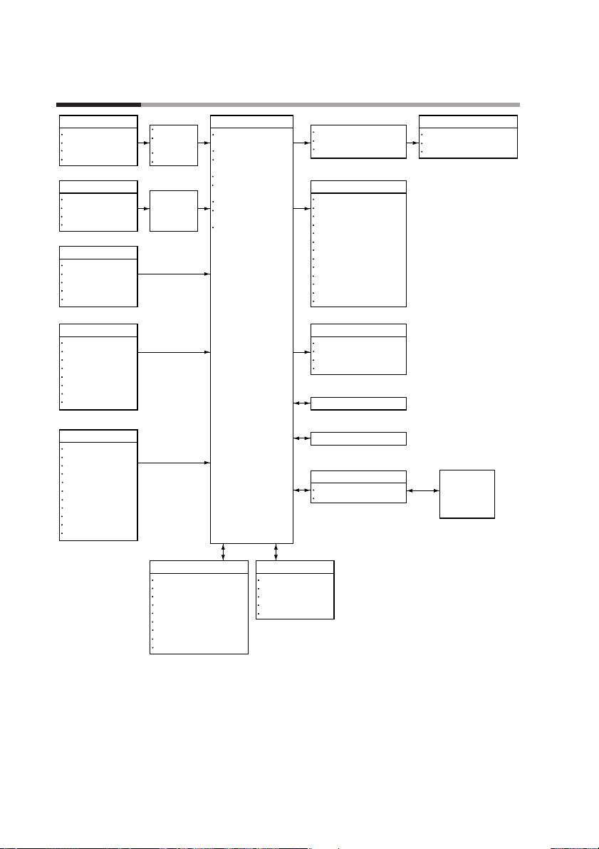
1 - 2 Basic Function Block Diagram
1-2
Chapter 1. PRODUCT OUTLINE
Input 1
Thermocouple
Resistance temperature detector
DC current
DC voltage
Input 2
Thermocouple
Resistance temperature detector
DC current
DC voltage
External switch input: 12 points
RUN
HOLD
RESET
ADV
Program No.
External switch input: 4 points
FAST
RAMP-E
AUTO/MANUAL
AT
G.SOAK reset
Forward-reverse operation
Auto load
PV1/PV2 selection
Key operation
Display selection
Program No.
RUN/HOLD
RESET
ADV
FAST
AUTO/MANUAL
AT
Program setting
Parameter setting
Memory card operation
Root extraction
Approximation by
linearization table
Bias
Filter
•
Root extraction
•
Approximation by
linearization table
•Bias
•Filter
Control operation unit
Mode transition
PID control
Auto tuning
Forward-reverse operation
ON-OFF control
SP limit
SP bias
PV2 channel selection
Output change limit
Upper and lower limit
SP output
Event output : 16 points
Time event
PV
SP
Deviation
MV
Code
Code with a timer
Each mode
Alarm
Segment No. code
Specific segment
Program No. code
PV change rate
Auxiliary output : 1 point/2 points
PV
SP
Deviation
MV
RS-485/RS-232C communication input/output
Loader communication input/output
Memory card
Program
Parameter
Output
Current proportionality
Volt-time proportionality
Open collector time proportionality
*
1
*
1
*
2
Memory Card
Reader Writer
+
Smart Loader
Package
*2*
3
Program Parameter
99 pattern X 99 segment
Event
PID group/output limiter group
G.SOAK
PV shift
Repeat
PV start
Cycle
Pattern link
Variable parameter
Event configuration
PID parameter
Setup
Constant value control
*
1 : Option for some models
*
2 : Option
*
This function is available on the
3 :
model only.
DCP551A
*****
Page 17
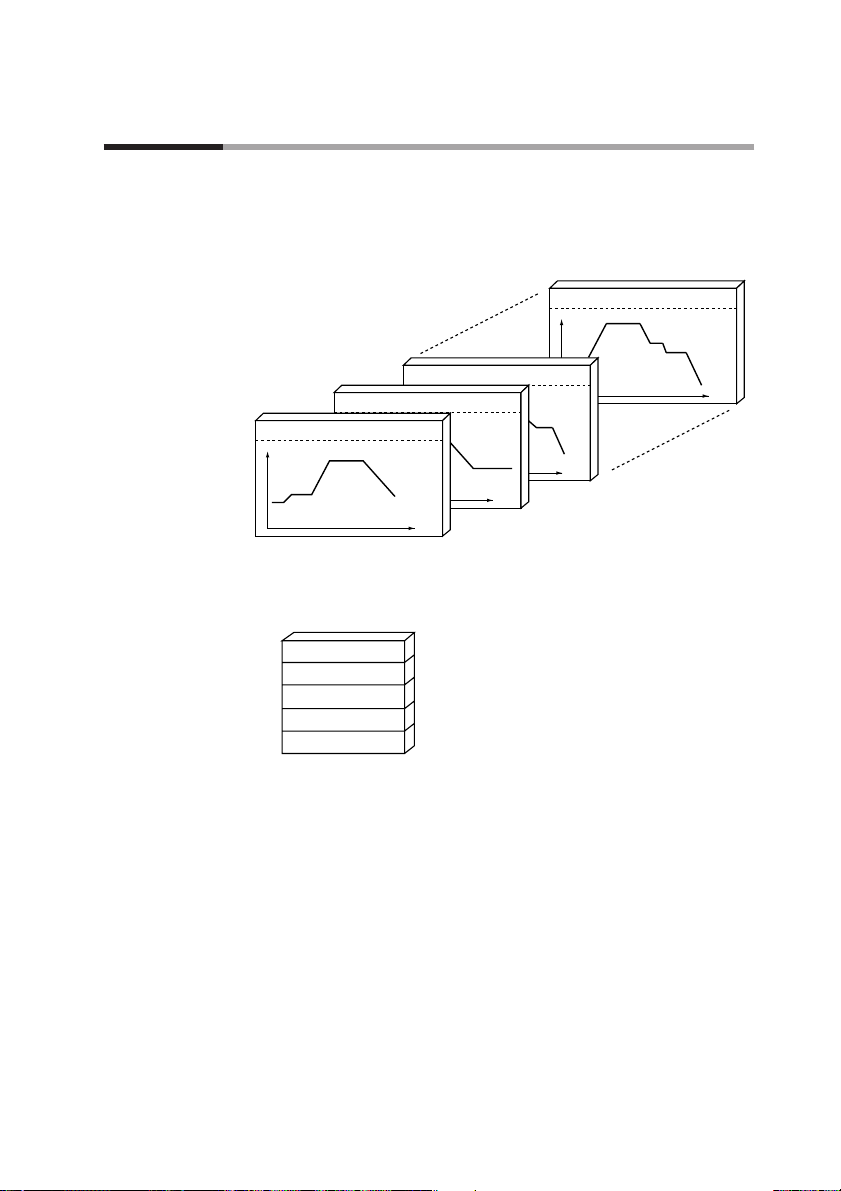
1 - 3 Data Configuration Overview
Data is comprised of parameters and the program.
Parameters are used to set the functions of the DCP551 while the program is the software that operates the
controller at run time.
● A total of 99 patterns
The program can record up to 99 patterns.
● Parameters
Five types of patterns are provided: variable parameters, event configuration data,
PID parameters, setup data and constant value control data.
1-3
Chapter 1. PRODUCT OUTLINE
Program number = 99 Segment count = 8
SP
Time
Program number = 3 Segment count = 15
Time
Program number = 2 Segment count = 19
SP
Time
Program number = 1 Segment count = 6
SP
Time
(1)
(2)
(3)
(4)
(5)
(6)
(18)
(19)
13)
(14)
(15)
(2)
(3)
(4)
(5)
(6)
(7)
(8)
Variable parameter
Event configuration data
PID parameter
Setup data
Constant valule control data
Page 18
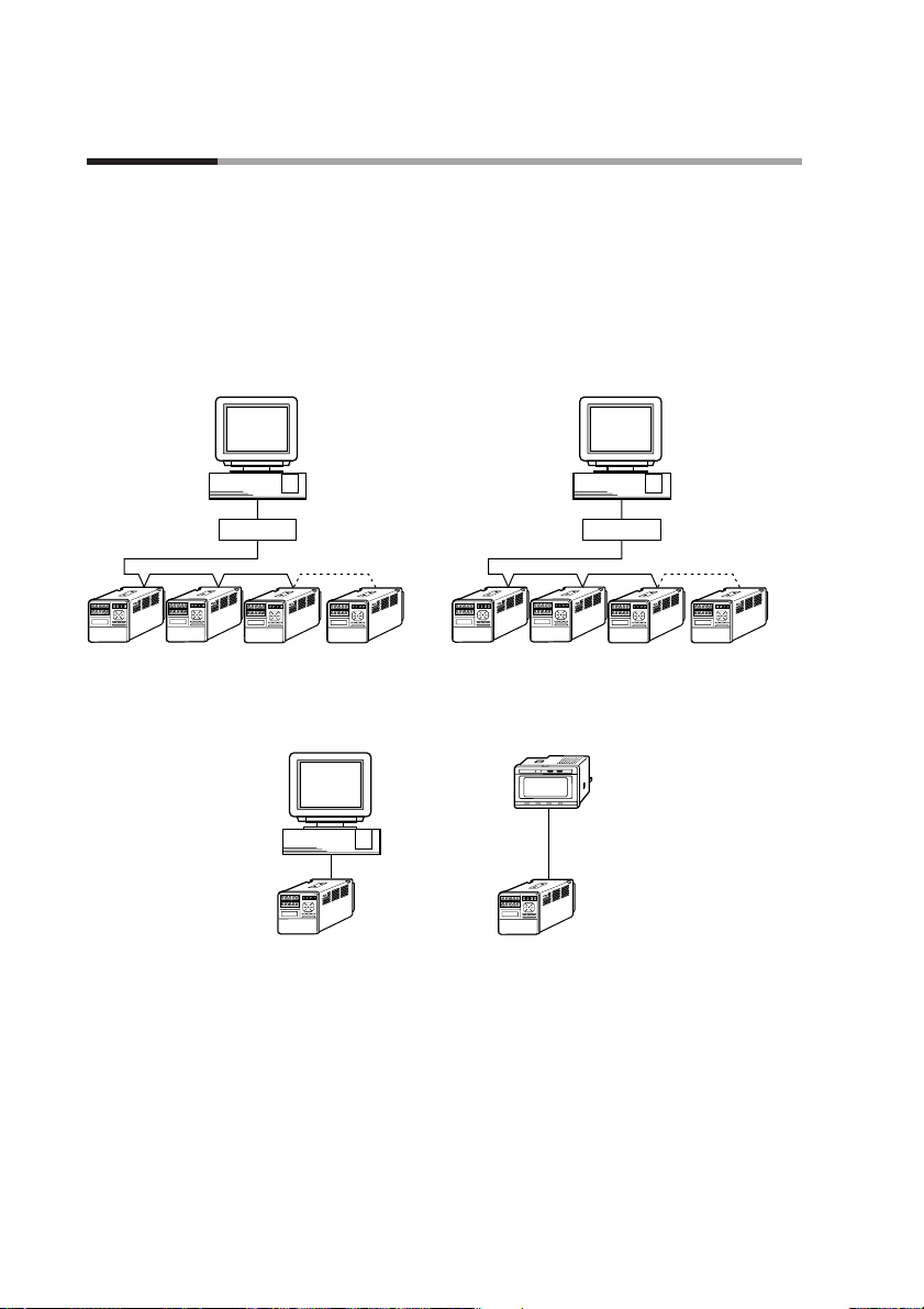
1 - 4 System Configuration
1-4
■ CPL communications network-based configuration
Models equipped with the optional communications interface can be connected as
a slaved DigitroniK’s controller to a CPL communications* network. In this case,
the user can employ as the master station a personal computer.
*: CPL(Controller Peripheral Link) Communications network is the host-
communications.
Chapter 1. PRODUCT OUTLINE
PC
PC PC
RS-232C
DCP551
(slave station)
DCP551
(slave station)
ST221DE05DCP (Smart Terminal dedicated display)
(slave station)
RS-485
DCP551 (master station)
RS-232C/RS-485 converter CMC10L001A000
RS-485 (5-wire system)
RS-485 Connection example
RS-485 (3-wire system)
*
* "Communication controller CMC10L001A000" is
RS-232C/RS-485(3-wire system) converter in Azbil corporation.
Page 19

1 - 5 Model Number
1-5
Chapter 1. PRODUCT OUTLINE
Basic mode
l
number
PV input
count
Additional
number
Memory
card
Additional
processing
Option
A
B
1
2
0
0
1
2
00
D0
Y0
DCP551
Contents
Digital programmable controlle
r
With memory card reader/writer
Without memory card reader/write
r
PV input 1 channel
PV input 2 channel
Fixed 0
Not provided
Auxiliary output 1 channel
Auxiliary output 2 channel, communication
Not provided
Inspection certificate provided
Model number :
DCP551✽ ✽ 0 ✽ ✽ ✽
Complying with the traceability
certification
✽✽ ✽✽✽✽
Page 20

Page 21

Chapter 2.
NAMES AND FUNCTIONS OF PARTS
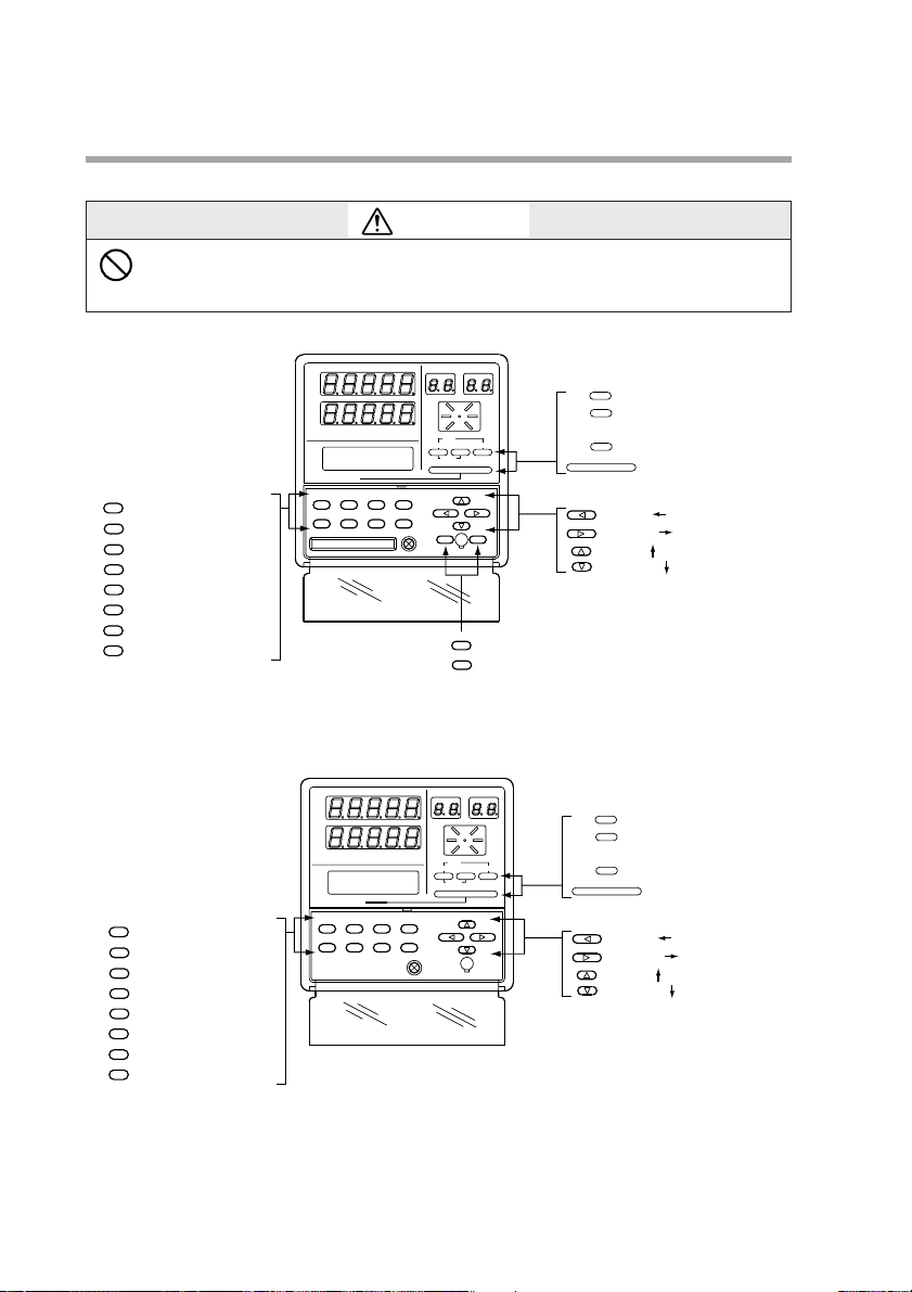
2 - 1 Structure
The DCP551 consists of a main unit, console, case, and terminal base.
DCP551A model DCP551B model
2-1
Console
Provides 7-segment displays, LEDs, operation keys,
and a loader interface unit.
Terminal base
Provides terminals to connect a power supply,
input, output, event output, external switch input,
and auxiliary output (optional) , etc.
Case
Main unit
Console and electric circuit board, etc.
Terminal cover
Covers power supply and
prevents electric shock.
FUNC AT SETUP ENTER
A/M PID PARA CLR
CARD
LOAD SAVE
LOADER
CYC
OUT
DEV
PV
SP
TM
SYN
RUN
HLD
MAN
PRG
AT
BAT
EG1
EG2
PROG RUN/HOLD DISP
RESET
PROG SEG
PROFILE
MESSAGE
MESSAGE
ADV
Lock screw
Secures case
to main unit.
Key cover
Prevents operation errors.
Memory card slot
A memory card is inserted into this slot.
PV
DEV
OUT
CYC
SP
TM
SYN
A/M PID PARA CLR
FUNC AT SETUP ENTER
MESSAGE
PROG SEG
PROFILE
RUN
HLD
MAN
PRG
ADV
PROG RUN/HOLD DISP
RESET
MESSAGE
LOADER
AT
BAT
EG1
EG2
Page 22
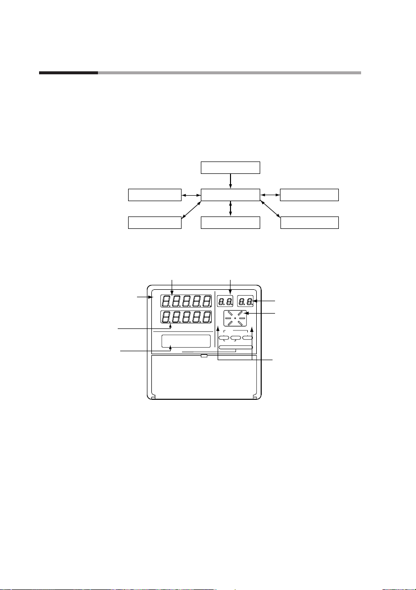
2 - 2 Console
2-2
The console consists of the operation keys, displays and LEDs (light emitting diodes).
■ Basic display status
Basic display status shows the running condition of the DCP551 on the console.
The basic display status is invoked when the DCP551 is powered up (power on).
Key operations make it possible to change from the basic display status to
parameter setting status, program setting status, program copy status, memory card
operation status* and general reset status.
Key operations can also be used to return to the basic display status.
* : This function is available on the DCP551A***** model only.
■ Display
● Basic display contents LED
PV : Lights during PV display, otherwise off.
DEV : Lights during deviation display, otherwise off.
OUT : Lights during output display, otherwise off.
CYC : Lights during cycle display, otherwise off.
SP : Lights during SP display, otherwise off.
TM : Lights during time display, otherwise off.
SYN : Off
Chapter 2. NAMES AND FUNCTIONS OF PARTS
Power on
Parameter setting status
Program setting status
Program copy status
Memory card operation status
General reset status
Basic display status
*
CYC
OUT
DEV
PV
SP
TM
SYN
RUN
HLD
MAN
PRG
AT
BAT
EG1
EG2
PROG RUN/HOLD DISP
RESET
PROG SEG
PROFILE
MESSAGE
MESSAGE
ADV
Display panel 1
(Upper display)
Program number display
(PROG display)
Segment number display
(SEG display)
Profile display
Mode display LED
Message display
LCD
(16 characters X 2 lines)
Display panel 2
(Lower display)
Basic display contents
LED
Page 23

2-3
● Display panel 1
Indicates PV and other data in basic display status.
Indicates item codes in parameter setting status.
Indicates set values and item codes in program setting status.
● Display panel 2
Indicates SP, time, output and other data in basic display status.
Indicates set values in parameter setting status.
Indicates set values in program setting status.
● Message display
Indicates output graph, deviation graph, running progress graph, event status,
program tag and other data in basic display status.
Displays reference messages in parameter setting status.
Displays tag settings and reference messages in program setting status.
Indicates selected operation and operation results during memory card
operation.
● Program number display
Indicates a selected program number in basic display status.
Indicates a set program number in program setting status.
Off during constant value control.
Indicates the alarm code “AL” when an alarm occurs in basic display status.
● Segment number display
Indicates a selected segment number in basic display status.
Indicates a set segment number in program setting status.
Off during constant value control.
Indicates an alarm code number when an alarm occurs in basic display status.
● Mode display LED
RUN, HLD : Indicates the RUN, HOLD, FAST, END, and READY FAST
modes (see the table below).
MAN : Lights in MANUAL mode. Off in AUTO mode.
PRG : Lights in program setting status, otherwise off.
AT : Flickers during auto tuning execution, otherwise off.
BAT : Flickers when battery voltage is too low, otherwise off.
EG1, EG2 : Lights when an event number output set by PA41 or PA42 is
set to ON setting. Off when set to OFF.
● Profile display
Indicates the rising, soaking, and falling trends of a program pattern.
Flickers during G.SOAK wait and lights continuously after power on.
Chapter 2. NAMES AND FUNCTIONS OF PARTS
Mode
LED
RUN
HLD
OFF
OFF
READY
Lights
OFF
RUN
OFF
Lights
HOLD
Flicker
OFF
FAST
OFF
Flickers
END
Lights
Lights
READY FAST
Page 24
2-4
■ Key pad
DCP551A model
DCP551B model
Chapter 2. NAMES AND FUNCTIONS OF PARTS
FUNC AT SETUP ENTER
A/M PID PARA CLR
CARD
LOAD SAVE
LOADER
CYC
OUT
DEV
PV
SP
TM
SYN
RUN
HLD
MAN
PRG
AT
BAT
EG1
EG2
PROG RUN/HOLD DISP
RESET
PROG SEG
PROFILE
MESSAGE
MESSAGE
ADV
: Program key (PROG key)
: Run/hold key
(RUN/HOLD key)
: Display key (DISP key)
: Message key
(MESSAGE key)
PROG
RUN/HOLD
DISP
MESSAGE
: Left key ( key)
: Right key ( key)
: Up key ( key)
: Down key ( key)
: Load key (LOAD key)
: Save key (SAVE key)
LOAD
SAVE
: Auto/manual key (A/M key)
: PID key (PID key)
: Parameter key (PARA key)
: CLR key (CLR key)
: Function key (FUNC key)
: Auto tuning key (AT key)
: Setup key (SETUP key)
: Enter key (ENTER key)
A/M
PID
PARA
CLR
FUNC
AT
SETUP
ENTER
( ) : Denotes key term used in this manual.
CAUTION
Do not use pointed objects such as mechanical pencils or pins to press the
keys on the controller.
This may result in malfunction.
A/M
PID
PARA
CLR
FUNC
SETUP
ENTER
: Auto/manual key (A/M key)
: PID key (PID key)
: Parameter key (PARA key)
: CLR key (CLR key)
: Function key (FUNC key)
AT
: Auto tuning key (AT key)
: Setup key (SETUP key)
: Enter key (ENTER key)
PV
DEV
OUT
CYC
SP
TM
SYN
MESSAGE
A/M PID PARA CLR
FUNC AT SETUP ENTER
( ) : Denotes key term used in this manual.
PROG SEG
PROFILE
RUN
HLD
MAN
PRG
ADV
PROG RUN/HOLD DISP
RESET
MESSAGE
LOADER
AT
BAT
EG1
EG2
PROG
: Program key (PROG key)
RUN/HOLD
: Run/hold key
(RUN/HOLD key)
DISP
: Display key (DISP key)
MESSAGE
: Message key
(MESSAGE key)
: Left key ( key)
: Right key ( key)
: Up key ( key)
: Down key ( key)
Page 25
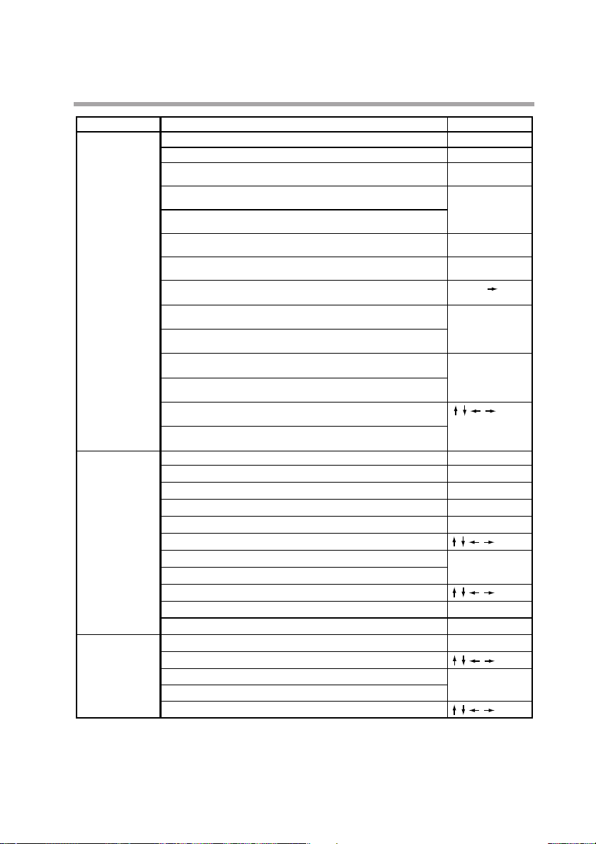
2-5
Chapter 2. NAMES AND FUNCTIONS OF PARTS
Classification
Basic display
status
Parameter setting
Program setting
Changes the display contents.
Key operation
DISP
Changes the display contents on the message display.
MESSAGE
PROGChanges set program numbers in ascending order.
(In READY mode)
RUN/HOLD
Performs RUN operation.
(In READY, HOLD, FAST, or READY FAST mode)
Performs HOLD operation.
(In RUN mode)
PROG + RUN/HOLD
Performs RESET operation.
(In RUN, HOLD, FAST, END, or READY FAST mode)
PROG + DISP
Performs ADV operation.
(In RUN, HOLD, FAST, or READY FAST mode)
FUNC +
Performs FAST operation.
(In RUN, HOLD, or READY mode)
A/M
Performs MANUAL operation.
(In AUTO mode)
Performs AUTO operation.
(In MANUAL mode)
AT
Starts auto tuning.
(When auto tuning is not in operation.)
Interrupts auto tuning
(When auto tuning is in operation.)
Changes numerics during MANUAL operation.
(When the MV or SV display flickers.)
Changes program numbers or segment numbers.
(When the program number or segment number flickers.)
PARAStarts the variable parameter setting. (In basic display status)
FUNC + PARA
Starts the event configuration setting. (In basic display status)
PID
Starts the PID parameter setting. (In basic display status)
SETUP
Starts the setup setting. (In basic display status)
FUNC + PID
Starts the fixed command control setting. (In basic display status)
Shifts each item.
ENTER
Enters set values.
Completes a change in a set value. (When a set value flickers.)
Changes each item s set point. (When a set value flickers.)
PARA
Stops each item s set point. (When a set value flickers.)
DISP
Ends parameter setting.
FUNC + PROG
Starts the program setting (programming). (In basic display status)
Shifts to program item or segment number.
ENTER
Enters set values.
Completes a change in a set values. (When a set value flickers.)
Changes each item s set point. (When a set value flickers.)
Function
Page 26
2-6
■ Key chord functions
PROG + RUN/HOLD : Reset key
Press the RUN/HOLD key while holding down the PROG key in basic status
display to perform a RESET.
The READY mode is invoked when a reset is performed in the RUN, HOLD,
FAST, END, or READY FAST modes. This RESET operation does not work
in the READY mode.
PROG + DISP : Advance key
Press the DISP key while holding down the PROG key in the program run mode
in basic status display to perform an ADV (advance) operation. The next segment
is displayed when this action is performed in the RUN, HOLD, FAST, END, or
READY FAST modes. This ADV operation does not work in the READY mode.
FUNC + : Fast key
Press the key while holding down the FUNC key in the program run mode
in basic status display to perform a FAST operation.
The system changes from the RUN or HOLD mode to the FAST mode. If the
system is in the READY mode, it goes to the READY FAST mode.
Chapter 2. NAMES AND FUNCTIONS OF PARTS
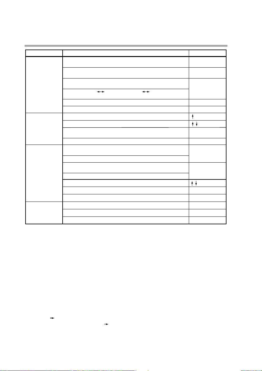
Classification
Program setting
Program copy
General reset
Memory card
operation
(available on the
DCP551A*****
model only)
Erases or resets a set value.
(When a set value flickers.)
Key operation
FUNC + CLR
Cancels change in set value.
(When a set value flickers.)
DISP
FUNC + ENTERInserts or delete a segment when a pattern SP setting is started.
FUNC + PROG
Changes RAMP-X RAMP-T or RAMP-X RAMP-E when a
pattern SP setting is completed.
Starts a program number change.
DISPEnds program setting.
+ PROG
Starts program copy. (In basic display status)
Changes program number at copy destination.
ENTERExecutes the copy.
(When a set value flickers.)
DISPEnds program copy.
SAVEStarts a data write operation to the memory card.
(In basic display status)
Writes data to the memory card.
LOADStarts a data read operation from the memory card.
(In basic display status)
Reads data from the memory card.
Changes selected memory card operation.
ENTER
Enters memory card operation.
DISP
Interrupts memory card operation.
FUNC + CLR + MESSAGE
Returns a check status of the general reset. (In basic display status)
ENTER
Executes a general reset.
DISP
Interrupts a general reset.
Function
Page 27

2-7
FUNC + PARA : Event configuration setting key
Press the PARA key while holding down the FUNC key in basic status
display to switch to the event configuration setting status.
FUNC + PID : Constant value control setting key
Press the PID key while holding down the FUNC key in basic status display
to switch to the constant value control setting status.
FUNC + PROG : Program setting (programming) key
Press the PROG key while holding down the FUNC key in the program run
mode in basic status display to go to the program setting (programming) status.
When the PROG key is pressed while holding down the FUNC key in the
program setting status, allows you to change the number of the program to be
set.
FUNC + CLR : Program delete key
Press the CLR key while holding down the FUNC key during registration in
the program setting status to delete a setting or return to a default value.
FUNC + ENTER : Segment insert/remove/RAMP/selection key
Press the ENTER key while holding down the FUNC key to go to the
segment insert/delete panel during SP and time setting in the program setting
status.
Pressing the ENTER key while the FUNC key is held down during SP
registration in the program setting status allows you to switch between RAMP-
X and RAMP-T as well as RAMP-X and RAMP-E.
+ PROG : Program copy key
Press the PROG key while holding down the key in program run READY
mode in basic display status to go to the program copy panel.
FUNC + CLR + MESSAGE : General reset key
Press the CLR and MESSAGE keys simultaneously while holding down the
FUNC key in the READY AUTO mode in the basic display status to go to the
general reset verification panel.
■ Loader jack
This jack allows the connection of a loader.
Do not insert plugs other than loader plugs.
The terminal base is not isolated from internal digital circuits.
When not in use, always replace the cap.
Chapter 2. NAMES AND FUNCTIONS OF PARTS
Page 28

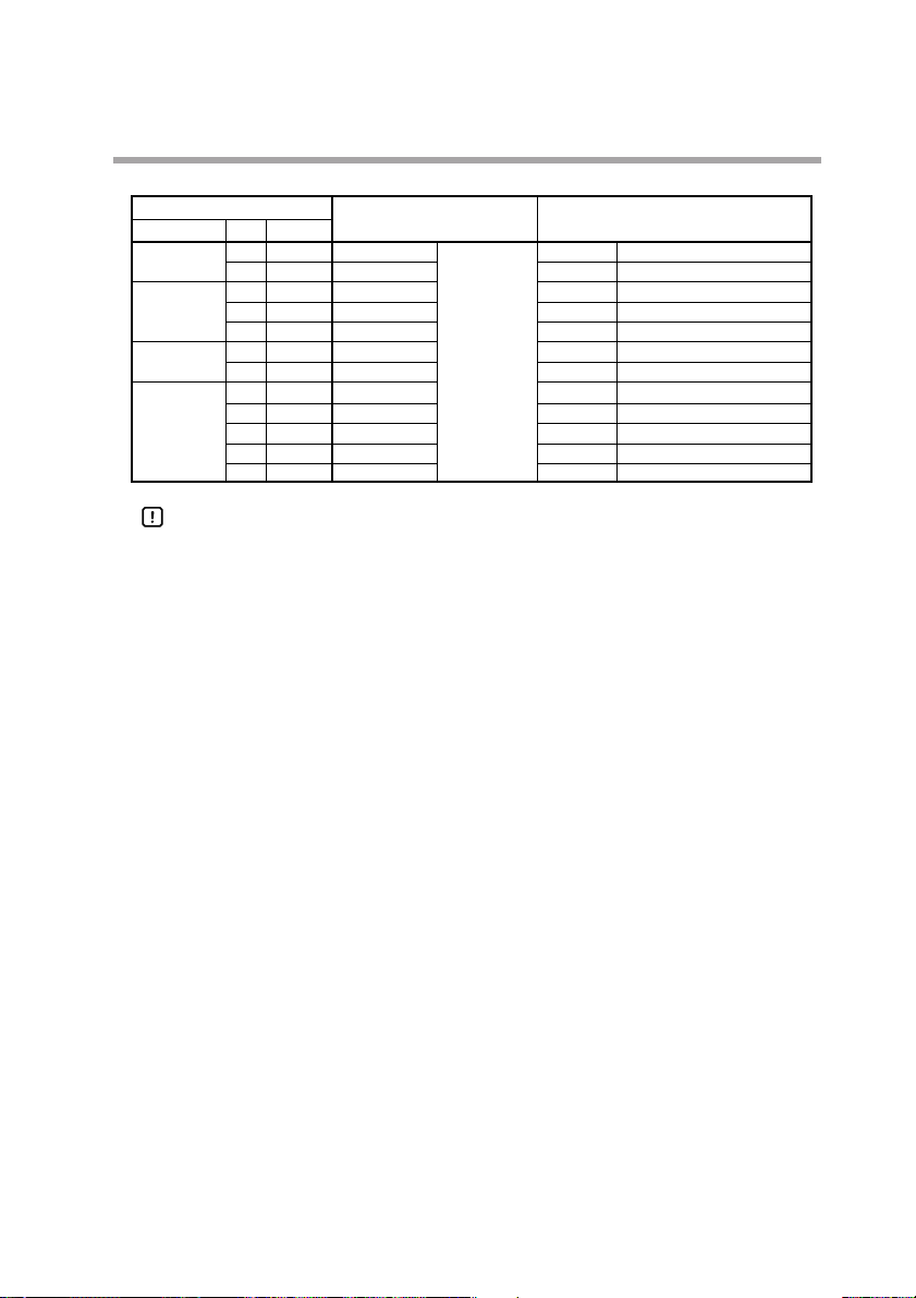
2 - 3 Input Type and Range Number
2-8
■ Input
● Thermocouple
● Resistance temperature detector (RTD)
Chapter 2. NAMES AND FUNCTIONS OF PARTS
Input type
Symbol
Code
Accuracy (under standard conditions)
±0.1%FS
Input range (FS)
Range No.
K (CA) K46
-200.0 to +200.016
-300.0 to +400.0
±0.1%FSK (CA) K09
0.0 to 1200.000 to 2400
±0.1%FSK (CA) K08
0.0 to 800.010 to 1600
±0.1%FSK (CA) K04
0.0 to 400.020 to 750
±0.1%FSE (CRC) E08
0.0 to 800.030 to 1800
±0.1%FSJ (IC) J08
0.0 to 800.040 to 1600
±0.1%FST (CC) T44
-200.0 to +300.0
5 -300 to +700
±0.1%FSB (PR30-6) B18
0.0 to 1800.060 to 3300
±0.1%FSR (RR13) R16
0.0 to 1600.070 to 3100
±0.1%FSS (PR10) S16
0.0 to 1600.080 to 3100
±0.1%FSW (WRe5-26) W23
0.0 to 2300.090 to 4200
±0.1%FSW (WRe5-26) W14
0.0 to 1400.010 0 to 2552
±0.2%FSPR40-20 D19
0.0 to 1900.011 0 to 3400
±0.1%FSN U13
0.0 to 1300.012 32 to 2372
±0.1%FSPL II Y13
0.0 to 1300.013 32 to 2372
±0.1%FSZ13
0.0 to 1300.014 32 to 2372
±0.4%FS
Gold, iron, chromel
Z06
0.0 to 300.0K (K : Kelvin)15
Input type
Symbol
Code
Accuracy (under standard conditions)
±0.1%FS
Input range (FS)
Range No.
JIS’89Pt100 F50
-200.0 to +500.064 -
300.0 to +900.0
±0.1%FSF46
-200.0 to +200.065 -
300.0 to +400.0
±0.1%FSF32
-100.0 to +150.0
66 -
150.0 to +300.0
±0.1%FSF36
-50.0 to +200.067 -50.0 to +400.0
±0.15%FSF33
-40.0 to +60.068 -40.0 to +140.0
±0.15%FSF01
0.0 to 100.069 0.0 to 200.0
±0.1%FSF03
0.0 to 300.070 0.0 to 500.0
±0.1%FSF05
0.0 to 500.071 0.0 to 900.0
±0.1%FSJIS’89Pt100 P50
-200.0 to +500.096 -
300.0 to +900.0
±0.1%FSP46
-200.0 to +200.097
-300.0 to +400.0
±0.1%FSP32
-100.0 to +150.098
-150.0 to +300.0
±0.1%FSP36
-50.0 to +200.099 -50.0 to +400.0
±0.15%FSP33
-40.0 to +60.0100 -40.0 to +140.0
±0.15%FSP01
0.0 to 100.0101 0.0 to 200.0
±0.1%FSP03
0.0 to 300.0102 0.0 to 500.0
±0.1%FSP05
0.0 to 500.0103 0.0 to 900.0
Page 29
2-9
● DC current, DC voltage
Handling Precautions
• The unit for code Z06 is “K” (kelvin).
• Code F50 and P50 do not generate the PV lower bound alarm.
• The number of decimal digits for DC current and DC voltage is
programmable from 0 to 4.
• The lower limit readout of code B18 is 20ºC (68ºF).
Chapter 2. NAMES AND FUNCTIONS OF PARTS
Input type
Symbol
Code
Accuracy (under standard conditions)
±0.1%FS
Input range (FS)
Range No.
mA
C01
4 to 20mA48
Programmable range
—19999 to +20000
(Decimal point
position is variable.)
±0.1%FS
(Linear)
Z51
2.4 to 20mA52
±0.1%FS
mV
M01
0 to 10mV49
±0.1%FSL02
-10 to +10mV50
±0.1%FS
0 to 100mV51
±0.1%FS
mA
C01
4 to 20mA128
±0.1%FS
(Linear)
Z51
2.4 to 20mA134
±0.1%FSV
0 to 1V129
±0.1%FS
(Linear)
-1 to +1V130
±0.1%FSV01
1 to 5V131
±0.1%FS
0 to 5V132
±0.1%FS
0 to 10V133
Page 30

Page 31

Chapter 3.
INSTALLATION AND MOUNTING
3- 1 Before Installation
■ Mounting position
Do not install the DCP551 in locations:
• exposed to high or low temperature or humidity.
• exposed to direct sunlight or to the elements such as outside.
• exposed to water, oil or chemicals.
• exposed to corrosive or inflammable gas.
• exposed to dust or smoke.
• exposed to vibrations or shocks.
• exposed to strong electric or magnetic fields.
• exposed to electric noise such as ignition devices or welding machines.
• Outdoors.
3-1
WARNING
Before removing, mounting, or wiring this module, be sure to turn off the
power to the module and all connected devices.
Doing so may result in an electric shock.
Do not disassemble the controller as this could lead to electric shock or
malfunction.
CAUTION
Be sure to follow the operating requirements (regarding temperature,
humidity, voltage, vibration, shock, mounting direction, atmosphere, etc.) as
stated in the specifications of the controller.
Failure to heed this caution may lead to fire or malfunction.
Do not block ventilation openings.
Failure to heed this caution may lead to fire or malfunction.
Make sure that wire scraps, chips, or water do not enter inside the case of the
controller.
Failure to heed this caution may lead to fire or malfunction.
Page 32

3-2
■ Sources of electrical interference and countermeasures
• The following noise generation sources are generally presumable.
(1) Relays and contacts
(2) Solenoid coils and valves
(3) Power lines (especially those carrying more than 90Vac)
(4) Inductive loads
(5) Inverters
(6) Motor rectifiers
(7) Phase angle control SCR
(8) Wireless communications equipment
(9) Welding machines
(10) High voltage ignition devices
• If the source of noise cannot be removed, take the following measures.
• Use a CR filter to suppress fast-rising noise.
Recommended CR filter : Model No. 81446365-001
• Use a varistor to suppress high-amplitude interference.
Recommended varistors : Model No. 81446366-001 (for 100V)
81446367-001 (for 200V)
Handling Precautions
Varistors must be handled carefully as they become defective if they are
short-circuited.
Chapter 3. INSTALLATION AND MOUNTING
Page 33

3 - 2 Installation
This section describes installation procedures.
■ Panel cutout dimension
Use 2mm thick steel panels in setting up the DCP551.
Handling Precautions
Install the DCP551 in a location where the lower panel is not exposed to
temperatures that exceed the operating temperature range (0 to 50°C).
Make sure that the temperatures above and below the controller meet
specified requirements.
3-3
Chapter 3. INSTALLATION AND MOUNTING
200 or more
450 or more
138
+1
0
138
+1
0
Unit : mm
Page 34

3-4
■ Installation procedures
• Use the provided mounting bracket to firmly secure the upper and lower panels.
• Assemble the instrument before carrying out mounting (1).
Handling Precautions
When the provided mounting brackets are firmly secured and there is
no looseness, turn the screws only one full turn. Over-tightening the
screws of the brackets can deform or damage the case.
• The rear of the instrument must not be more than 10° above or below the
horizontal plane.
Chapter 3. INSTALLATION AND MOUNTING
Mounting (2)
Mounting (1)
Mounting bracket
Mounting bracket
Page 35

Chapter 4. WIRING
4 - 1 Precautions on Wiring
4-1
CAUTION
Connect the controller as specified using designated cables and connection
procedures.
Failure to heed this caution may lead to electric shock, fire or malfunction.
Make sure that wire scraps, chips or water do not enter inside the case of the controller.
Failure to heed this caution may lead to fire or malfunction.
Current applied to current input terminals
(55), (56) and (58), (59)
must meet
the specified range.
Failure to heed this caution may lead to fire or equipment breakdown.
All terminal screws shall be tightened to specified torque.
Improperly tightened screws may lead to electric shock or fire.
Do not use unused terminals on the instrument as relay terminals for other
equipment. Failure to heed this caution may lead to electric shock, fire or
equipment breakdown.
Attaching the terminal covers after completing the controller connections is
highly recommended.
Failure to heed this caution may lead to fire or malfunction. (Terminal covers
are supplied with the controller.)
If there is a risk of a power surge caused by lightning, use a surge protector
to prevent fire or device failure.
Be careful not to allow crimp terminal lugs to touch adjacent terminals.
WARNING
Connect the FG terminal to ground with a ground resistance of maximum
100Ω before connecting other equipment and external control circuits.
Failure to do so may cause electric shock or fire.
Before removing, mounting, or wiring this module, be sure to turn off the
power to the module and all connected devices.
Doing so may result in an electric shock.
Do not touch a live part such as a power terminal.
This may result in electric shock.
Page 36

4-2
Handling Precautions
• Before connecting the lines, verify the model number and terminal
numbers on the label affixed to the side panel of the DCP551. After
completing, always double check to ensure all wiring has been
performed correctly before turning on the power.
• The I/O signal lines and the communications lines shall maintain at least
50cm between them and the power supply line and power supply cables.
Do not route these cables through the same conduit or duct.
• Make sure that no crimp-style solderless wire connectors are touching an
adjacent terminal or connector.
• When connecting a thermocouple input of the DCP551 to another
instrument, make sure the instrument’s input impedance totals at least
1MΩ. If less than 1MΩ, the DCP551 may not be able to detect sensor
disconnection.
• Cautions when using data input devices in combination
Input of the DCP551 input or output (connected in parallel for input) to an
A/D converter, analog scanner, etc., may cause dispersion of the read
data. To prevent such occurrence, take one of the following corrective
measures.
(1) Use a low-speed integral A/D converter.
(2) Insert an isolator with no switching power supply between the
DCP551 and the A/D converter.
(3) Perform averaging with a personal computer when the data is read.
(4) If the device permits, insert an input filter.
• Devices and systems to be connected to this must have the basic
insullation sufficient to with stand the maximam operating voltage levels
of the power supply and input/output parts.
Chapter 4. WIRING
Page 37

4 - 2 Recommended Cables
To perform thermocouple input, connect a thermocouple element to the terminals. When the wiring distance is long
or when connecting the thermocouple without the element to the terminals, connect via shielded compensating lead
wires.
NOTE
• For I/O other than thermocouple, use JCS4364 instrument cable or equivalent
(is commonly called twisted shielded cable for instrument use).
The following cable are recommended.
• A shielded multicore microphone cord (MVVS) may be used, if electromagnetic
induction is comparatively low.
´
´
!
"
´
"
´
4-3
Chapter 4. WIRING
Page 38

4 - 3 Making Terminal Connections
4-4
To connect a line to the terminals, use crimp-style solderless wire connectors that fit an M3.5 screw.
Handling Precautions
• If the DCP551 is mounted in a location subject to noticeable vibration or
impact, be sure to use round crimp-style solderless wire connectors to
prevent lines from becoming disconnected from the terminals.
• Be careful not to allow any of the crimp-style solderless wire connectors
to touch adjacent terminals or connectors.
• The terminal screws shall be tightened to 0.78 to 0.98 N
•
m torque.
Chapter 4. WIRING
Unit : mm
7.4
7.3 or less
6.6 or less
3.7
Page 39

4 - 4 Terminal Array
Wires are connected to the terminal base according to the layout shown below.
4-5
Chapter 4. WIRING
DI
123451627384
12
5678
COM1
13 1412
10
9
DI
COM2
11
41
2625
12
3029
141513
3433
16
3837
ABC
RTD
3
15
OUT *AUX
43 44 45 46 48 49 50 51 52 53
+–
mA
T/C
mV. V
PV CH1 *PV CH2
45
16 17
ABC
RTD
LOAD LOAD
DO DO
DO
COM1
18 19
+++–
T/C
mV. V
SDA SDBSDRDA RDBRDSGSG(RS-485)
O2
mA
*COMM * : OPTION
MADE IN JAPAN 40733000100
10 118967
11912
–+–+–+–+
10
23 2420 22
13
27 28
31 32
39 40
FGAUX2AUX1OUT2OUT1
6463626160595857565554
DO
COM2
161415
(RS-232C)
Page 40

4 - 5 Power Supply and Grounding
4-6
■ Power supply
To supply power to the DCP551, use an instrument-dedicated single-phase power
supply subject to minimal electrical interference.
Handling Precautions
• If electrical interference proves excessive, we recommend adding an
insulating transformer and/or using a line filter.
Azbil Corporation model no.: 81442557-001
• After carrying out interference reducing measures, do not bundle the
primary and secondary power supply coils together or insert them in the
same conduit or duct.
■ Grounding
If grounding the shield wire or other lines proves difficult, ground them separately
to a grounding terminal block.
Ground resistance : Less than 100Ω
Conductor : Annealed copper wire, min. 2mm2(AWG14)
Max. Length : 20m
Handling Precautions
To ground the DCP551, connect the FG terminal (terminal
(52) or (53)
)
to a single ground point without jumpering.
Chapter 4. WIRING
Instrument power supply
100 to 240Vac
50/60Hz
Other circuits
Less than 100
200/200V
100/100V
Insulating transformer
Recommended product
81442557-001
Line filter
E
2
Grounding
GND
DCP551
31
4
Grounding
39
40
53
52
or
DCP551
53
or
52
FG terminals
Grounding terminal block
Shield
Page 41

4 - 6 PV Input (Analog Input) Connection
■ PV input CH1 connection
PV input CH1 is a multi-input type input for sensors. Connect as shown below,
according to the type of sensor being used.
■ PV input CH2 connection
PV input CH2 is a multi-input type input for sensors. Connect as shown below,
according to the type of sensor being used.
4-7
Chapter 4. WIRING
CAUTION
Current applied to current input terminals
(55), (56) and (58), (59)
must meet
the specified range.
Failure to heed this caution may lead to fire or equipment breakdown.
Thermocouple input Resistance temperature detector input
+ -
54 55 56
DC voltage input
+
54 55 56
+ -
Thermocouple input
+ -
57 58 59
T/C
-
ABC
54 55 56
RTD
DC current input
- +
54 55 56
- +
Current (mA)
transmitter
Resistance temperature detector input
ABC
57 58 59
T/C
RTD
Page 42

4-8
Handling Precautions
• Be careful to connect the input polarities correctly.
• Use shielded cable to connect the input.
Chapter 4. WIRING
DC voltage input
+ -
57 58 59
+ -
DC current input
- +
57 58 59
- +
Current (mA)
transmitter
Page 43

4 - 7 Control Output Connection
■ Current output (5G, 5S)
■ Vo ltage output (6D)
Handling Precautions
The voltage output is a constant current circuit inside. The SSR used is set
to an optimum voltage to meet the requirements of hte load. Enter the
value in the setup data. A normal SSR voltage has been set at the factory
before shipment.
■ Open collector output (8D)
Handling Precautions
• Do not short-circuit the positive (+) terminal of the external power supply
to terminal (43) on the DCP551. Doing so causes the open collector
outputs to malfunction. (There is no short circuit preventing circuit inside.)
• When connecting a semiconductor load such as a programmable
controller (sequencer), select a module in which the current directions
match.
Use one made inoperative by the leakage current produced when the
digital outputs are shut off.
4-9
Chapter 4. WIRING
WARNING
Be sure to turn off the power supply when you are installing or removing the
controller. Failure to do so may cause electric shock or fire.
+ -
43
+ -
Load
44
4 to 20mAdc
Load resistance less than 600
Ω
43 44
43
+ -
Load
+-
+-
SSR
44
12 to 24Vdc
2to22mAdc
With current value adjustment function
(Setup data
Max. load current : 100mA
Leakage current when off : less than 0.1mA
C95
)
Page 44

4 - 8
Auxiliary Output (Output CH1, CH2) Connection
4-10
■ Auxiliary output CH1 connection
■ Auxiliary output CH2 connection
Chapter 4. WIRING
WARNING
Before removing, mounting, or wiring this module, be sure to turn off the
power to the module and all connected devices.
Doing so may result in an electric shock.
+ -
48
49
+ -
Receiver
+ -
50
51
+ -
Receiver
4 to 20mAdc
Load resistance less than 600
4 to 20mAdc
Load resistance less than 600Ω
Ω
Page 45

4 - 9
Event Output (Open Collector Output) Connection
Handling Precautions
• Do not short-circuit the positive (+) terminal of the external power supply
to terminals (5) to (8), (17) to (20), (10), (11), (22), (23), (27), (28), (31),
and (32) on the DCP551. Doing so causes the open collector outputs to
malfunction. (There is no short circuit preventing circuit inside.)
• When connecting a semiconductor load such as a programmable
controller (sequencer), select a module in which the current directions
match.
Use one made inoperative by the leakage current produced when the
digital outputs are shut off.
4-11
Chapter 4. WIRING
EV9 EV10 EV11 EV12 EV13 EV14 EV15 EV16
EV1 EV2 EV3 EV4 EV5 EV6 EV7 EV8
Load
5
Load
10
Load
Load
Load
Load
Load
Load
Load
Load
+
—
+
—
External power supply
12 to 24Vdc
External power supply
12 to 24Vdc
Max. load current
Max. common current
Leakage current when OFF
Max. load current
Max. common current
Leakage current when OFF
: 70mA/point
: 500mA
: less than 0.1mA
: 70mA/point
: 500mA
: less than 0.1mA
11
Load
6
Load
7
8 17 18 19 20 9
Load
Load
Load
Load
22
23 27 28 31 32 24
Page 46

4 - 10 External Switch Input Connection
4-12
● Internal circuit diagram of the DCP551 connecting external switch input
Handling Precautions
• The inputs of the DCP551 unit are provided with a built-in power supply
(open voltage type, 8.5Vdc). Always use no-voltage contacts externally.
• For the no-voltage contacts, use gold contacts or other relays that switch
on small currents. Other types of relay contacts may not switch. Use
contacts that have ample margin over the minimum switching capacity
with respect to the current and open voltage ratings of contacts provided
on the DCP551.
• If using semiconductors (open collectors, etc.) as no-voltage contacts,
use one that maintains a potential of no more than 2V across the
contacts when actuated, and a leakage current of no more than 0.1mA
when shut off.
• The digital inputs (remote switch inputs) of all SDC40 and SDC10 series
units can be connected in parallel. If connecting them in parallel to
another instrument, carefully check the requirements of the other
instrument before proceeding.
• Do not connect SDC20/21, SDC30/31 series in parallel. Doing so may
cause the external switch input to malfunction.
• Common terminals (12) and (41) of the external switch input are
connected internally.
Chapter 4. WIRING
SW1 SW2 SW3 SW4 SW5 SW6 SW7 SW8
ADV
RESET
HOLD
RUN
3
1 2
SW9 SW10 SW11 SW12 SW13 SW14 SW15 SW16
1 2 4 8 10 20 40 80
25 26
4 13 14 15 16 12
29
30 33 34 37 38
: With BCD
41
8.5Vdc
8.5Vdc
Internal
circuit
Page 47

4 - 11 Communication Connection
■ RS-485 connection
Handling Precautions
• The slave station can be connected in a multi-drop configuration.
• Always set a unique address to each slave station.
• Attach terminating resistances (a total of four when connecting a 5-wire
system) to the ends of the communications lines. Use 1/2W or greater
terminating resistances of 150Ω ±5%.
• If connecting three lines, short-circuit terminals (60), (62) and (61), (63).
• Do not short-circuit the RDA to RDB and SDA to SDB terminals.
Doing so may cause the DCP551 to malfunction.
4-13
Chapter 4. WIRING
SDB
RDA RDB SGSDA
60
61 62 63 64
Page 48

4-14
● 5-wire system RS-485 connection diagram
Attach 1/2W or greater terminating resistances of 150Ω ±5% at each end of the
communications lines. Ground the shield FGs at one end in one location, not at
both ends.
Handling Precautions
Be sure to connect SG terminals each other.
Failure to do so might cause unstable communications.
Chapter 4. WIRING
Terminating resistor
Terminating resistor
Shield
Master station
RDA
RDB
SDA
SDB
SG
FG
Terminating resistor
Terminating resistor
Shield
Shield
Slave station side DCP551
SDA
60
SDB
61
RDA
62
RDB
63
SG
64
FG
Slave station side DCP551
SDA
60
SDB
61
RDA
62
RDB
63
SG
64
FG
Slave station side DCP551
SDA
60
SDB
61
RDA
62
RDB
63
SG
64
FG
Page 49

4-15
● 3-wire system RS-485 connection diagram
Handling Precautions
In the 3-wire system, the CMC10L001A000 can be used as a converter in
the master station.
Attach 1/2W or greater terminating resistances of 150Ω ±5% at each end of the
communications lines. Ground the shield FGs at one end in one location, not at
both ends.
When only three RS-485 terminals are provided, the areas designated with an
asterisk (*) are connected internally.
Handling Precautions
Be sure to connect SG terminals each other.
Failure to do so might cause unstable communications.
Chapter 4. WIRING
Terminating resistor
Master station
RDA
RDB
SDA
*
SDB
*
SG
FG
Terminating resistor
Shield
Shield
Shield
Slave station side DCP551
SDA
60
SDB
61
RDA
62
RDB
63
SG
64
FG
Slave station side DCP551
SDA
60
SDB
61
RDA
62
RDB
63
SG
64
FG
Slave station side DCP551
SDA
60
SDB
61
RDA
62
RDB
63
SG
64
FG
Page 50

4-16
■ RS-232C connection
Handling Precautions
• Connect the slave station to the master station in a single-drop (point-topoint) configuration.
• There are three (RD, SD and SG) communications terminals on the
RS-232C interface on the master station which may not output data if not
short-circuited as shown above.
Chapter 4. WIRING
Example of connection
SD
RD SG
61 63 64
1234567
CDRDSDERSGDRRS
8
Host computer (master station)
CS
Page 51

4-17
NOTE
RS-232C connector signals (9 pins)
Example : IBM and compatibles
■ Connection to ST221
Handling Precautions
• Attach 1/2W or greater terminating resistances of 150Ω ±5% at each end
of the communications lines.
• The DCP551 operates as a master station when connected to an ST221
during communications.
Chapter 4. WIRING
RxD
Signal direction
Host Instrument
Pin No.
1
2
3
4
5
6
7
8
JIS code
CD
RD
SD TxD
ER DTR
SG GND
DR DSR
RS RTS
CS CTS
SG
Name
DCD
60 61 62 63 64
3 4 1 2 5
ST221DE05DCP
Page 52

4 - 12 Isolation During Input/Output
4-18
Isolation between inputs and outputs are shown below. In this figure, the solid lines enclose mutually-isolated
sections. Those sections bounded by dashed lines are not isolated.
Handling Precautions
The terminal base is not isolated from internal digital circuits.
When not in use, always replace the cap.
Chapter 4. WIRING
PV input CH1
PV input CH2
Loader communication
External switch input
Communication
Memory card input*
* : available on the DCP551A***** model only
Digital
circuit
Control output
Auxiliary output CH1
Auxiliary output CH2
Event output
Page 53

Chapter 5. FUNCTIONS
5 - 1 Data
5-1
■ Data types
The data types are listed below.
For further information on data types, see “Chapter 7. PARAMETER SETUP”
and “Chapter 8. PROGRAM SETUP”.
Data Parameter Variable parameter
Constant value control data
Setup data
PID parameter
Event configuration data
Program Pattern
PV shift
G.SOAK
PID group and output
limiter
group number
Event
Repeat
Tag
Pattern link
Cycle
PV start
Data changeable in RUN mode
Event type data
PID group and output limiter group control parameters
Basic data only changeable in the READY mode
Constant value control SP, PID and other data
SP and time, SP and θ or SP and
∆
SP data
Data for event 1 to 16
Data for PID group number used for control
and output limiter group number
Data indicating whether G.SOAK is provided or not
PV shift data
Data indicating whether repeat is used or not
Data indicating whether PV start is used or not
Cycle count data
Pattern link destination program number data
Tag (8 characters) data
Page 54

5 - 2 Program Pattern
5-2
■ Pattern
Three systems for selecting programs are provided: RAMP-X, RAMP-T and
RAMP-E. The first segment of each program is always RAMP-X, but the other
segments can be any system and all three types can be used in one program.
● RAMP-X system
This system, sets a segment of a pattern using SP and time, is called RAMP-X.
SP setting : within the upper and lower SP limiter range
Time setting : 0 hours 00 minutes to 500 hours 00 minutes
0 minutes 00 seconds to 500 minutes 00 seconds or
0.0 seconds to 3000.0 seconds
(Time units are selected using the C62 setup data setting.)
SP is a point on the elapsed time axis in the current segment, which is a straight
line connecting the start point, the SP set value in the previous segment, and the
end point, the SP set value in the current segment. Segments are classified as
follows.
•Rising RAMP (or rising slope)
Previous segment SP setting < current segment SP setting
•Falling RAMP (or descending slope)
Previous segment SP setting > current segment SP setting
•SOAK (soaking)
Previous segment SP setting = current segment SP setting
The start and end points of the first segment are also the SOAK segment of the SP
set value for the first segment.
SP calculation (other than first segment)
SP = (current segment SP set value – previous segment SP set value)
× (current segment elapsed time ÷ current segment time setting)
+ previous segment SP setting.
Chapter 5. FUNCTIONS
Time setting of current segment
SP set value of
previous segment
SP set value of
current segment
Page 55

5-3
● RAMP-T system (θsetting)
In the RAMP-T system, a segment is set using SP and ramp θ(theta).
SP setting : within the upper and lower SP limiter range
θ
setting : 1 to 10000 (SPU/hour, SPU/min, SPU/sec)
(Time units are selected using the C62 setup data setting.)
SP is a point on the elapsed time axis in the current segment which is an extended
straight line, the ramp set value of the current segment when the SP set value in
the previous segment is the start point.
The end point is the point where this line reaches the SP setpoint of the current
segment. Note that the RAMP-T system cannot be used in the first segment.
SP calculation: SP = θset value × segment elapsed time + previous segment SP.
● RAMP-E system (∆ SP setting)
In the RAMP-E system, segments are set using SP and ∆ SP (digital SP) for each
external switch input pulse.
SP setting : within the upper and lower SP limiter range
∆ SP setting: 1 to 10000 SPU
The start point is the SP set value in the previous segment.
SP is a value resulting from adding a multiple of the external switch input count to
the SP set value when the SP in the previous segment is the start point.
The segment ends when this SP reaches the SP setting in the current segment and
the current segment SP is more than the previous segment SP or when current
segment SP is less than the previous segment SP.
SP calculation: when current segment SP is more than the previous segment SP,
SP = ∆ SP set value × external switch input count + the previous segment SP.
When current segment SP is less than the previous segment SP,
SP = – (∆ SP set value × exernal switch input count) + the previous segment SP.
Chapter 5. FUNCTIONS
SP of previous
segment
setting
θ
Unit time
(Set unit time using setup data
SP setting of
current segment
C62
.)
Current segment SP setting
SP of previous
segment
External switch input (1)
(Set external switch input using one of setups
SP setting
(2)
SP setting
C71
to
C74
. )
Page 56

5-4
NOTE
• Select the program pattern setting system using setup data setting C61.
0: combined use of RAMP-X and RAMP-T
1: combined use of RAMP-X and RAMP-E
• Select time setting units using setup data setting C62.
0: hours and minutes
1: minutes and seconds
2: 0.1 seconds
• Select θ setting units using setup data setting C62.
0: SPU/hour
1: SPU/min
2: SPU/sec
• Select SP setting and SP setting decimal position using setup data setting C65.
0: XXXXX
1: XXXX.X
2: XXX.XX
3: XX.XXX
4: X.XXXX
• External switch for pulse input requires 1: RAMP-E using a setup data setting
between C71 to C74.
• The pulse input interval time can be checked by setting event type 93 in the
event. Event type 93 is RAMP-E time monitored during a period of 0.0 to
3000.0 seconds.
Even when a setting is exceeded and there is no pulse input, the event remains
on.
Chapter 5. FUNCTIONS
Page 57

5-5
■ Events
The event configuration data setting allows event types to be set for event outputs
1 to 16.
Events are of the following four types: time event, PV event, code event and mode
event. Settings are divided into two types of events: segment events and
instrument event.
• Segment events are used to set the event operating point in a program setting
and makes it possible to set different set values in different segments. But in the
constant value control mode segment events are off.
• Instrument events are used to set events that do not require an event operating
point or set the event operating point in the event configuration setting. It
performs operations that are shared by all program operations and constant
value control.
● Time events
The On Time or both the On and Off Time can be set by event number and
segment. Output on/off duration are as shown below.
NOTE
•The On Time is indicated by the length of the line from the start of the
segment until the upturned arrow.
•The Off Time is indicated by the length of the line from the start of the
segment until the downturned arrow.
• When the On Time is less than the off time, the output is on from the on time
until the off time.
(See segments 1, 6 and 7 in the figure.)
• When only an on setting is made, the output stays on until the end of the
segment. (See segments 2 and 5 in the figure.)
• The output is off when no On or Off Time has been set.
• An off time cannot be set without setting an on time. (See segment 3B in the
figure.)
Chapter 5. FUNCTIONS
Segment
On-time
Off-time
Output-ON
Output-OFF
ON<OFF
1
Segment
On-time
Off-time
Output-ON
Output-OFF
The output goes off at the end of the
segment when no off time is set.
2 3
Page 58

5-6
• An On Time ≥ Off Time setting cannot be made.
(See segment 3C in the figure.)
• An On Time or Off Time is valid only within a segment and cannot straddle
segments. In the next segment, the On time and Off time set for that segment
are valid. (See segments 4 and 5 in the figure.)
Thus an On Time and Off Time setting made at the end of a RAMP-X segment
are ignored. (Compare segment 9 with the G.SOAK wait in segment 10 in the
figure.)
Note, however, that an On Time or Off Time setting at the end of a RAMP-T
segment is either valid or invalid depending on the computational error.
• When the On Time is set to 0 (no Off Time being set or set to more than 0), the
output goes on when the On Time becomes 0. If the output was on at the end of
the previous segment, it stays on and does not go off momentarily between the
two segments. (See segments 5 and 6 in the figure.)
• The G.SOAK Time is not included in the On and Off Time. (See segment 7.)
Nor is the Wait Time included for a G.SOAK that occupies an entire segment.
Chapter 5. FUNCTIONS
Segment
On-time
Off-time
Output-ON
Output-OFF
3B 3C
No On Time is set.
ON=OFF ON>OFF
Segment
On-time
Off-time
Output-ON
Output-OFF
An On or Off Time that is set to be
longer than the segment time
is not valid.
4 5
Segment time
Continues into segment 5.
Segment
On-time
Off-time
Output-ON
Output-OFF
5 6
ON=0
ON duration
Segment
On-time
Off-time
Output-ON
Output-OFF
G.SOAK wait
Segment start
7
Page 59

5-7
• When there is a G.SOAK wait at the start of a segment and the ON Time is set
to 0, the output goes on at start of the G.SOAK wait and the On Time starts as
the G.SOAK wait ends.
The output time = G.SOAK time + (Off Time – On Time) (See segment 10 in
the figure.)
• An On Time and Off Time occurring at the end of a RAMP-X segment are valid
when there is a G.SOAK wait at the end of a segment or as the end state of the
final segment. (See segment 10 in the figure.)
Note, however, that an On Time or Off Time setting at the end of a RAMP-T
segment is either valid or invalid depending on the computational error.
Chapter 5. FUNCTIONS
Segment
On-time
Off-time
Output-ON
Output-OFF
G.SOAK wait Start of segment 8
The output goes on at the start of
segment 8 when on is set to 0.
8
Segment
On-time
Off-time
Output-ON
Output-OFF
Segment
On-time
Off-time
Output-ON
Output-OFF
Segment time
ON = Segment time
9
ON = Segment time
10
G.SOAK wait
Page 60

5-8
• When there is a G.SOAK at the end of the previous segment, the On Time in
the next segment is ignored if it is set to 0. (See segments 11 and 12 in the
figure.)
Thus the ON = 0 of segment 12 is not output at the end of the set time for
segment 11, but when the G.SOAK wait ends.
• This function can be combined with an event ON delay set using PARA. Delay
works when an event goes from off to on. A delay is not triggered when an On
Time continues across two segments as shown in segments 5 and 6 in the
figure.
● PV event
• Basic specifications
The difference between PV, deviation, absolute value deviation, SP, MV and
PV1-PV2 for each event type is shown on the following pages. The thick lines
show ON and OFF conditions. The upper line indicates ON and the lower line
indicates OFF conditions.
EV indicates the event set value and H indicates the hysteresis value. Outputs in
READY mode are OFF. But normal PV1 upper and lower limit operation and
normal PV2 upper and lower limit operation events run also in the READY
mode.
• Event standby
Standby events operate as described below.
• If the event is in the gray area shown in the figure during a change from
READY to RUN mode or when the power is restored after an outage, the
event operates without a standby. The upturned arrows in the figures indicate
ON while the downturned arrows indicate OFF.
• If the event is outside the gray area shown in the figure during a change
from READY to RUN mode or when the power is restored after an outage, it
remains off until it enters the gray area .
After entering the gray area , the upturned arrows in the figures indicate
ON while the downturned arrows indicate OFF.
A standby event is off in the READY mode.
Chapter 5. FUNCTIONS
Segment
On-time
Off-time
Output-ON
Output-OFF
Segment
On-time
Off-time
Output-ON
Output-OFF
Segment time
ON=0
11
G.SOAK wait
12
Page 61

5-9
• Event on delay
The number of the event to be delayed and the delay time can be set regardless
of event type. The delay turns on the output for the duration of the delay when
the event meets the conditions for going from OFF to ON. When this function
is combined with the event standby function, the event on delay operates when
the standby state is cleared.
• Segment event progress
• The output stays OFF until the program reaches a segment with an event.
• The event goes ON or OFF according to the set value of the event.
• Previous settings are valid until segments with other event settings are
reached.
• Previous settings are valid when the program has reached segment number 1
using the cycle function or pattern link function. The output is turned off if
there is no event in segment number 1.
• Other functions
The MV forward/backward event does not operate when the C21 setup data
setting is set to 0 during SP output (programmer function).
Normal PV2 upper and lower limit operation events and PV1-PV2 differential
of upper limit and lower limit events during automatic PV channel switching do
not operate on models with only one PV input channel.
Normal PV1 upper and lower limit operation event and normal PV2 upper and
lower limit operation events operate in the READY mode.
Chapter 5. FUNCTIONS
PV upper limit
Normal PV1 upper limit operation
Normal PV2 upper limit operation
PV lower limit
Normal PV1 lower limit operation
Normal PV2 lower limit operation
H
EV
Deviation upper limit
Deviation upper limit with standby
H
SP+EV
Absolute value deviation upper limit
Absolute value deviation upper limit with standby
SOAK absolute value deviation upper limit*
SOAK absolute value deviation upper limit with standby*
H
EVEV
Items marked * operate only in SOAK segments.
SP
PV
Deviation lower limit
Deviation lower limit with standby
PV
Absolute value deviation lower limit
Absolute value deviation lower limit with standby
SOAK absolute value deviation lower limit*
SOAK absolute value deviation lower limit with standby*
H
PV
H
EV
H
SP+EV
H
EV
EV
Items marked * operate only in SOAK segments.
SP
PV
PV
H
PV
Page 62

5-10
Chapter 5. FUNCTIONS
SP upper limit
H
EV
MV upper limit
H
EV
PV1-PV2 differential upper limit
H
EV
PV1-PV2 differential upper limit during
automatic PV channel selection
EV
Note: When the output goes on, it stays
on until READY mode.
SP lower limit
SP
MV lower limit
MV
PV1-PV2 differential lower limit
PV1-PV2
PV1-PV2 differential lower limit during
automatic PV channel selection
PV1-PV2
Note: When the output goes on, it stays
EV
EV
EV
EV
on until READY mode.
H
H
H
SP
MV
PV1-PV2
PV1-PV2
Page 63

5-11
● PV deviation rate event
PV deviation is measured in each sampling cycle set using eventconfiguration
while on/off states are determined by comparing event setting deviation rate PVs.
PV deviation between sampling cycles is ignored. Event on/off switching is
performed according to the sampling cycle. This function can be combined with
event on delay.
Chapter 5. FUNCTIONS
Set event value is more than 0 (using upper limit event)
PV
Set event
value
Sampling cycle
PV deviation rate
upper limit event
operation
PV deviation rate
lower limit event
operation
(1) (2) (3) (4)Sampling
Set event value is less than 0 (using lower limit event)
PV
OFF
ON
Set event value
Set event value
ON (up alarm)
OFF
Set event value
Time
OFF
ON
PV deviation rate
upper limit event
operation
PV deviation rate
lower limit event
operation
Sampling cycle
(1) (2) (3) (4)Sampling
ON
Set event value
OFF
ON (down alarm)
Set event value
Time
ON
OFF
Page 64

5-12
● Code event
Several events are used as one group and the number of output points are output
as one parallel code number. Assigning code numbers to event outputs has the
same effect as increasing the number of physical output points.
• Code event
Set event type to code event and set the number of output points (1 to 8) in
auxiliary setting 1. An output code value (0 to 255) can be set for each segment.
A binary coded low-order bit for the set number of output points is output.
The previous setting is valid until the program reaches a segment with a new
setting.
Note, however, that unless a setting is made in the first segment, the program
will assume that a set value of 0 is set in the first segment.
Chapter 5. FUNCTIONS
Example: Setting a code event involving 3 output points in event 3
The table below shows the output state when a value of 3 is set in segment 2, a value of 6
is set in segment 4 and a value of 0 is set in segment 5.
Segment
Set value
Code value
1 in event 3
Code value
2 in event 4
Code value
4 in event 5
Output code
12 543
Not set 3 Not set 6 0
OFF
OFF
OFF OFF
0
OFF,OFF,OFF
0, 0, 0
ON ON
ON
3
OFF,ON,ON
0, 1, 1
ON ON
OFF
3
OFF,ON,ON
0, 1, 1
OFF
ON
6
ON,ON,OFF
1, 1, 0
OFF
OFF
OFF
0
OFF,OFF,OFF
0 , 0, 0
Page 65

5-13
• Timed code event
This function is a combination of a code event and a time event. The set code
value is output at the set time. The number of settings that can be made in the
first segment is the same as the number of output points. For example, for a 3-
point output up to three settings can be made in the first segment.
Like a time event, a time within the time of the segment is valid and those that
exceed the value are ignored. When the program reaches the start time of the
first segment or a new segment, the set code value is 0 (all points off) until the
set time of the time event.
Chapter 5. FUNCTIONS
Example: Setting a timed code with 3 output points in event 3
The table below shows the output state when a value of 5 is set in segment 2 and set to start at the
beginning of the segment, a value of 3 is set to occur 0:10 after the start of segment 2 and a value
of 4 is set to occur 0:30 after the start of segment 4.
Segment
Set value
Set time Not set 0.00 0.10 Not set 0.30 0.00
12 543
Not set 5 3 Not set 6 0
Time
Code value
1 in event 3
Code value
2 in event 4
Code value
4 in event 5
Output code
*1:
OFF
OFF
OFF
0
OFF,OFF,OFF
0, 0, 0
ON,OFF,ON
1, 0, 1
0.10
ON ON
OFF
ON
5
*1
OFF,ON,ON
*2:
0, 1, 1
ON
OFF
3
*2
OFF OFF
OFF OFF
OFF OFF
3
OFF,OFF,OFF
0, 0, 0
OFF,OFF,OFF
*3:
0, 0, 0
0
*3
0.30
OFF
ON
ON
6
*4
ON,ON,OFF
*4:
1, 1, 0
OFF
OFF
0
OFF,OFF,OFF
0 , 0, 0
Page 66

5-14
• Program/segment number event
A program or a binary coded segment number is set in an event type and the
number of output points (1 to 7) is set in auxiliary setting 1. Or a program or a
BCD code of the segment number is set in an event type and the number of
output points (1 to 8) is set in auxiliary setting 1.
A selection, a program designed for a specific operation or a coded segment
number is output. A low-order bit code corresponding to the set number of
output points is output.
• An event on delay can be combined with the code event.
Note, however, that when there are several channel code events, the delay has
to be entered for each channel.
Chapter 5. FUNCTIONS
Decimal binary code comparison table
Decimal
1
2
3
4
5
6
7
8
9
10
11
12
13
14
15
16
17
Binary code output
(0: Off output 1: On output)
0 0 0 0 0 0 1
0 0 0 0 0 1 0
0 0 0 0 0 1 1
0 0 0 0 1 0 0
0 0 0 0 1 0 1
0 0 0 0 1 1 0
0 0 0 0 1 1 1
0 0 0 1 0 0 0
0 0 0 1 0 0 1
0 0 0 1 0 1 0
0 0 0 1 0 1 1
0 0 0 1 1 0 0
0 0 0 1 1 0 1
0 0 0 1 1 1 0
0 0 0 1 1 1 1
0 0 1 0 0 0 0
0 0 1 0 0 0 1
•
•
•
Decimal BCD code comparison table
Decimal
1
2
3
4
5
6
7
8
9
10
11
12
20
30
40
50
BCD code output
(0: Off output 1: On output)
0 0 0 0 0 0 0 1
0 0 0 0 0 0 1 0
0 0 0 0 0 0 1 1
0 0 0 0 0 1 0 0
0 0 0 0 0 1 0 1
0 0 0 0 0 1 1 0
0 0 0 0 0 1 1 1
0 0 0 0 1 0 0 0
0 0 0 0 1 0 0 1
0 0 0 1 0 0 0 0
0 0 0 1 0 0 0 1
0 0 0 1 0 0 1 0
0 0 1 0 0 0 0 0
0 0 1 1 0 0 0 0
0 1 0 0 0 0 0 0
0 1 0 1 0 0 0 0
•
•
•
•
•
•
Page 67

5-15
● Mode event
This event goes on or off depending on controller mode, alarm generation and
other states.
It cannot be combined with the event standby function but with the on delay
function. It does not set event set values (operating points) or hysteresis.
• Basic operations
The following types are provided.
RUN + HOLD + END + FAST
HOLD
READY + READY FAST
END
G.SOAK wait
MANUAL
During auto-turning execution
FAST + READY FAST
Console setting operation
RUN
ADV (advance)
Full alarm (logical OR)
PV range alarm
Instrument alarm
PV1 selected
PV2 selected
Battery voltage drop
The event goes on when the specified instrument state is reached and is off at
other times.
• Alarm
Alarms are of two types: PV range alarm group (alarm code number 01 to 04)
and instrument alarm group (alarm code number 91 to 99 and battery voltage
drop). When the event type is all alarm, the event goes on if one alarm occurs.
When the event type is a PV range alarm, the event goes on if one alarm in the
PV range alarm group goes on.
When the event type is an instrument alarm, the event goes on if one alarm in
the instrument alarm group goes on.
•ADV
When ADV (advance) is executed, the event goes on for 1 second. This
function is valid during on delay.
Chapter 5. FUNCTIONS
Page 68

5-16
■ PID group selection
• ID groups can be selected in two ways: by setting a PID segment or through
automatic PID group switching.
A PID group segment and automatic PID group switching can also be
combined. When a PID group number is set to 0, the setting in the previous
segment is continued.
• In a PID group segment setting a PID group number is set in each segment and
PID parameters are used for calculating the control output. The nine PID groups
PID1 to PID9 can be used.
• In automatic PID group switching, the entire SP scale is divided into seven
zones assigning CP-A1 to CP-A6 to each. The PID constants that are used
according to SP values are automatically selected to calculate control output.
The PID group number for each segment specifies A. Seven PID groups from
PID-A1 to PID-A7 can be used.
■ Selection of ouput limiter group
• Output limiter group number can be set for each segment to control the lower
limit (OL) and upper limit (OH) of the control output. oL and oH groups 1 to 9
can be used.
• The output limiter can only be specified by segment; automatic selection cannot
be made.
• When the output limiter is set to 0, the setting in the previous segment is
continued.
Chapter 5. FUNCTIONS
PID group number
1234
PID group segment setting
CP-A6
CP-A5
CP-A4
CP-A3
CP-A2
CP-A1
Automatic PID group selection
Zone 7
Zone 6
Zone 5
Entire SP range is
divided into seven zones.
Zone 4
Zone 3
Zone 2
Zone 1
Page 69

5-17
■ G.SOAK (Guarantee soak)
G.SOAK on/off state, type and G.SOAK width is set by the segment. G.SOAK are
of three types: segment start point, segment end point and the entire segment.
G.SOAK time is set using the variable parameter PA46 setting. Any offset
between SP and PV triggers a G.SOAK wait which narrows the distance between
SP and PV to guarantee the segment execution time. G.SOAK operates not only
on SOAK but also on RAMP segments.
Note, however, that in FAST mode a G.SOAK setting does not trigger a G.SOAK
wait.
G.SOAK can be cleared with an external switch input. The following types of
clearing conditions can be selected using setup data setting C71 to C74.
(1) G.SOAK is cleared when an external switch contact is set to on or when PV
meets the G.SOAK clearing conditions.
(2) G.SOAK is cleared when an external switch contact is set to on and PV meets
the G.SOAK clearing conditions.
• G.SOAK at start of segment
PV and SP are compared at the beginning of the segment. The segment starts
when the absolute value of the difference continues beyond the G.SOAK time
and becomes narrower than G.SOAK width.
A G.SOAK wait state continues until these conditions are met which is
announced by the flashing of the linear LED on the left of the profile display.
The operating condition is the same as HOLD at the beginning of a segment
(time = 0).
Chapter 5. FUNCTIONS
SP
G.SOAK
width
G.SOAK
width
SP
PV
Segment
setting time
Segment
executing time
G.SOAK wait time
Time
Page 70

5-18
• G.SOAK at end of segment
PV and SP are compared at the end of the segment. The operation in that
segment ends when the absolute value continues beyond the G.SOAK time and
becomes narrower than G.SOAK width.
A G.SOAK wait state continues until these conditions are met which is
announced by the flashing of the linear LED at the center of the profile display.
The operating condition is the same as HOLD at the end of a segment (time =
set segment time).
• G.SOAK for entire segment
PV and SP are compared at across the entire segment. The operation in that
segment continues when the absolute value continues beyond the G.SOAK time
and becomes narrower than G.SOAK width.
A G.SOAK wait state continues until these conditions are met which is
announced by the flashing of the linear LED at the left and the center of the
profile display.
The operating condition is the same as HOLD at the continued time.
■ PV shift
A PV correction value can be set for each segment. PV is PV input value plus PV
bias and PV shift. Note, however, that in the READY mode and the constant value
control mode, PV bias but not PV shift is added to the PV input value.
The setting in the previous segment continues when PV shift is set to “-----”
(nothing).
Chapter 5. FUNCTIONS
SP
G. SOAK
width
G. SOAK
SP
PV
width
Segment
setting time
G.SOAK wait time
Time
SP
+10˚C
PV
PV input value
Time
+5˚C
Nothing
+10˚C 0˚C
A “No PV shift setting” that continues from the first
segment has the same effect as a PV shift 0°C setting.
+5˚C setting is continued.
Segment number
PV shift setting
+5˚C
12 3 456
Nothing Nothing
Page 71

5-19
■ Repeat
Repeat on/off and return destination are set by the segment with the segment
number and repeat count. Operation completes at the end of a segment. If there is a
repeat setting, the program returns to the start of the set destination segment and
operation is resumed from there. This operation is repeated the number of times
specified by the repeat count.
No repeat is performed when the destination segment number is larger than the
current segment number. When the program returns to the first segment, PV is not
started even if a PV start setting has been made.
Handling Precautions
• When repeat operations involve multiple segments and the destination
segment settings overlap, nest or intersect, the repeat operation will
become an abnormal eternal loop. Do not make such settings.
• When the current segment does not contain a set value or the value is 0,
executed values for program items (for example, set PV event values or
set PID group selection values) that are sequels to settings in a previous
segment are the same during the first run and the repeat run.
Chapter 5. FUNCTIONS
Segment1Segment2Segment
Segment
3
4
Segment
Segment1Segment2Segment3Segment
Segment
1
Example of a double
Intersect example (1)
Segment
2
3
Segment1Segment2Segment3Segment
Example of a nest
4
Segment1Segment
Intersect example (2)
4
Segment
2
3
Page 72

5-20
■ PV start
When a PV start is set in the program setting, a PV start is performed in a normal
RUN operation.
The program looks for the first point where PV and the program pattern SP are
equal (both PV and SP include bias) and starts operation from there. PV starts are
of three kinds: rising PV start that looks for a point where PV and SP are equal on
a rising RAMP, falling PV start that looks for a point where PV and SP are equal
on a falling RAMP and bi-directional PV start that looks for such a point both on
rising and falling RAMPs.
Note, however, that if there is no point where PV and SP are equal, operation
starts from the beginning of segment 1.
When a PV start has been implemented, the event operating point and the time
event time are automatically corrected. This is described in the figure shown
below. When PV is at (1) in the figure, a rising PV start or a bi-directional PV start
starts from B and a falling PV start starts from C. When PV is at (2) in the figure,
a falling PV start or a bi-directional PV start starts from D and a rising PV start
starts from A. When PV is at (3) in the figure, any PV start starts from A.
NOTE
PV start is valid for segments in the selected program but not for segments beyond
a pattern link destination.
Chapter 5. FUNCTIONS
SP pattern
Current PV value
(1)
A
(2)
(3)
B
C
D
Page 73

5-21
■ Cycle
The cycle function allows you to repeat operation from segment 1 to the last
segment in a program pattern the number of times set in the cycle count. A total of
10,000 times can be set.
When a cycle number of n is set, the total operation count is n + 1. During cycle
operation, the operation at the last point in the final segment is not performed and
executed values of program items (sequels to settings in the previous segment ; for
example, PV event value, pid group number) that continue from a previous
segment are cleared before program restart.
When the SP start point and end point are not equal, SP changes in a step-like
manner during cycle operation.
Chapter 5. FUNCTIONS
SP
(5)
(4)
(3)
(2)
(1)
(6)
Cycle 1
Time
Page 74

5-22
■ Pattern link
The pattern link function links patterns; the program number of the link at the
destination is set in the pattern link item. An initial value of 0 indicates that linking
is not performed.
When the number of the program is set in the pattern link item, it forms an eternal
loop.
When SP at the end of the original link and SP at the destination are not equal, SP
changes in step-like manner.
When cycle operation has been set, the pattern link operates after the cycle
operation has been completed.
Since operation starts from the first segment at the destination during pattern
linking, executed values of program items (sequels to settings in the previous
segment) that continue from a previous segment are cleared before program
restart.
When a PV start has been programmed in a pattern at the destination link, the PV
start function operates after the link has been made.
PID computations are not initialized but continued after a link has been
established.
When the READY mode is invoked at the end of an operation or in a RESET
operation, operation returns to program number 1 that is switched from READY to
RUN mode (RUN to READY). If a RESET is performed when a program at the
pattern link destination is reached during an ADV operation in the READY mode,
operation returns to segment 1 of the link destination program number. Note,
however, that program numbers selected using the external switch takes priority.
Chapter 5. FUNCTIONS
Linking program No. 1 and program No. 2
SP
Program No.1
Program No.2
SP
SP
Program No.1
Time
Time
Program No.2
Time
Page 75

5-23
■ Ta g
Tags are 8-character alphanumerics, katakana or symbols that can be entered in a
program.
When segment 1 pattern item is set in a program setting, a total of eight characters
consisting of PROG plus two characters in the program number and “__” two
space characters.
Example: Program no. 1 : “PROG01__”
Program no. 19 : “PROG19__”
Chapter 5. FUNCTIONS
Page 76

5 - 3 Mode
5-24
■ Mode types
Modes are listed below.
● Program operation
The program is run according to SP, time, events and other settings made in
program patterns 1-99.
● Constant value control
The control is run according to SP and events made with the constant value control
data.
● READY
READY indicates that the program is ready to run.
MV becomes fixed and events whose operation depends on values set in the
segments are turned off. Note, however, that DCP551 state dependent events still
run.
Program numbers between 1 to 99 and set segment numbers can be selected during
program operation.
All setup data, some event configuration data and some constant value control data
parameters can be changed in the READY mode.
Memory cards can also be used in the READY mode.
Chapter 5. FUNCTIONS
Mode
Program operation
Constant value
control
READY
READY FAST
RUN
HOLD
FAST
END
READY
RUN
AUTO
MANUAL
AUTO
MANUAL
AUTO
MANUAL
AUTO
MANUAL
AUTO
MANUAL
AUTO
MANUAL
AUTO
MANUAL
AUTO
MANUAL
Page 77

5-25
● RUN
The RUN mode indicates that the program is run sequentially.
MV output and events operate during PID control, ON-OFF control and other
types of control. In the program RUN mode, program operation progresses
according as time elapses. Note, however, that G.SOAK (guarantee soak) wait,
like the HOLD mode, halts program operation.
● HOLD
The HOLD mode temporarily halts program operation.
Note, however, that, like the RUN mode, MV output and events operate during
PID operation, ON-OFF control and other types of control. During constant value
control the HOLD mode cannot be invoked.
● FAST
The FAST mode is essentially a speeded-up version of the RUN mode. The time
factor is selected using variable parameter PA39. MV output and events operate
during PID control, ON-OFF control and other types of control. G.SOAK
(guarantee soak) settings are ignored.
During constant value control the FAST mode cannot be invoked.
● END
The END mode indicates the state of a program that has run its course.
When a program stops at the end, MV output and events operate during PID
control, ON-OFF control and other types of control.
During constant value control the END mode cannot be invoked.
● READY FAST
The READY FAST mode is a combination of the READY and FAST modes.
MV output, SP output and events operate in the same way as in the READY mode.
Program numbers and segment numbers cannot be selected. Parameters that can
only be changed in the READY mode and memory card operation is not possible
in this mode.
During constant value control the READY FAST mode cannot be invoked.
● AUTO
The AUTO mode performs automatic operation. MV outputs can be used
depending on DCP551 control. (Note, however, that when programmer functions
are selected, DCP551 dependent SP outputs operate.)
● MANUAL
The MANUAL mode performs manual operation.
The “ ”, “ ”, “ ” and “ ” console keys can be used to change
communications and MV output.
(Note, however, that when setter functions are selected, communications and SP
output can be changed.)
Chapter 5. FUNCTIONS
Page 78

5-26
■ Mode transitions
● Program operation
Mode transitions are indicated by the solid line arrows and end operation is
indicated by the dashed lines in the figure below.
NOTE
• AUTO ⇔ MANUAL mode changes can be made in the boxes of each mode.
• READY and END at the end of operation can be selected using setup data
C31.
● Constant value control
Mode transitions are indicated by the solid line arrows.
NOTE
AUTO ⇔ MANUAL mode changes can be made in the boxes of each mode.
● Switching between program operation and constant value control
Constant value control data “ConSt ” control mode item in the READY mode is
used to switch between these two modes.
0: Program operation
1: Constant value control
NOTE
Constant value control is available only when setup data setting C21 is set to
more than 0. When C21 is set to 0, ConSt is also set to 0.
Chapter 5. FUNCTIONS
END AUTO
END MANUAL
RESET
ADV
RESET
READY AUTO
READY MANUAL
FAST
READY FAST AUTO
READY FAST MANUAL
RESET
ADV
RUN
RESET
RUN AUTO
RUN MANUAL
RUN
ADV ADV
HOLD
RUN
FAST
RUN
FAST AUTO
RESET
FAST MANUAL
HOLD AUTO
HOLD MANUAL
FAST
HOLD
ADV
READY AUTO
READY MANUAL
RUN
RESET
RUN AUTO
RUN MANUAL
Page 79

5-27
■ Mode transition operations
Mode transitions are performed using the following operations.
Although “Operation end” is not an operation, it is described here as a factor in
mode transitions.
● RUN
Switches from the READY, HOLD, FAST and READY FAST modes to the RUN
mode. To go from the READY mode or READY FAST to the RUN mode using
keys, external switches or transmission, the DCP551 must be in basic display
status.
● HOLD
Switches from the RUN and FAST modes to the HOLD mode. During constant
value control the HOLD mode cannot be invoked.
● RESET
Switches from the RUN, HOLD, FAST, END and READY FAST modes to the
READY mode.
In program operation, the reset involves returning the program to the first segment.
● ADV
Brings the program forward by one segment in the READY, RUN, HOLD, FAST
and READY FAST modes. ADV (advance) operation is not available in the
constant value control mode.
● FAST
The FAST mode is invoked from the RUN, HOLD, READY and READY FAST
modes. During constant value control the FAST mode cannot be invoked.
● AUTO
Switches from the MANUAL mode to AUTO mode.
● MANUAL
Switches from the AUTO mode to MANUAL mode. The basic display status
changes as follows during this transition.
•A controller function displays PV and output value (%).
• The programmer function displays PV and SP.
Switching from AUTO to MANUAL using external switches or transmission
invokes the basic display status even when the parameter setting status or
programmer setting status are in use.
● Operation end
Operation ends when all progress of program settings including cycle and pattern
links reach the end in the RUN, FAST and READY FAST program operation
modes or during an ADV operation. By making a setup selection, it is possible to
set READY or END as the state of the controller when the program reaches its
end.
Note, however, that when an operation ends in the READY FAST mode, it always
ends in the READY mode. In constant value control mode, operation end is not
available.
Chapter 5. FUNCTIONS
Page 80

5-28
■ Mode transition restrictions
Modes can be changed using console keys, external switch inputs or through
communications. The table below shows the operations that are valid for each
mode.
❍ : Valid operation
❁ : Operation from basic display status valid
∆ : Returns to the first segment remaining in the READY mode.
✽ : Operation is invalid, but the communication end code is normal if performed
in the basic display status.
- : Invalid operation
* ADV operation performed via communications may not go to the next segment
but to the segment set in the communications message.
Chapter 5. FUNCTIONS
Operation RUN
Original mode
Program
operation
Constant
value
control
Operation MANUAL
Original mode
Program
operation
Constant
value
control
READY
RUN
HOLD
FAST
END
READY
FAST
READY
RUN
AUTO
MANUAL
AUTO
MANUAL
(
To RUN mode
Key
Switch Commu-
nication
❁
❁
–
–
❍
❁
❍
❁
–
–
❁
❁
❁
❁
–
–
(To MANUAL mode)
Key
Switch Communication
❁❁❍❍❁
HOLD
)
(To RUN mode)
Key
Switch Commu-
–
❁
❁
✽
–
❁
–
❁
–
–
–
❁
–
❁
–
✽
Key
✽
❁
✽❁❁❍❍
(To READY mode)
Key
nication
–
–
–
❁
❁
❍
❁
✽
–
❁
❁
❍
❁
–
–
❁
–
–
–
–
–
❁
–
–
AUTO
(To AUTO mode)
Switch Communication
✽
❁
✽
❁
RESET
Switch Commu-
nication
✽
∆
❁
❍
❁
❍
❁
❍
❁
❍
❁
❍
✽
–
❁
❍
ADV
(To next segment)
Key
Switch Commu-
nication*
–
❁
–
❁
❍
❁
❁
❍
❁
❁
❍
❁
–
–
–
❁
❍
❁
–
–
–
–
–
–
FAST
(To FAST or
READY FAST mode)
Key
Switch Commu-
nication
❁
❁
❁
❁
❍
❁
❁
❍
❁
✽
–
–
–
–
–
✽
–
–
–
–
–
–
–
–
Page 81

5 - 4 Controllers and Programmers
Setup data C21 allows the user to select the controller function or the programmer function.
● Controller
PID controller computations can be performed using PV, SP and PID set values
and the result of the manipulated variable is output via an analog output.
ON-OFF control can be used instead of PID control.
In the MANUAL mode, manipulated variable levels can be controlled by keys
available in the basic display status.
● Programmer
PID control computations are not performed and 4 to 20mA output of scaled SP
signals are output.
In the MANUAL mode, SP levels can be controlled by keys available in the basic
display status.
NOTE
The constant value control mode cannot be invoked when the programmer
function is used.
5-29
Chapter 5. FUNCTIONS
PV
DCP551
Controller
MV
PV
Controlled process
DCP551
Programmer
SP output
SDC series
controller
4 to 20mA
SDC series
controller
RSP input
SDC series
controller
MV
PV
Controlled process Controlled process Controlled process
PV
MV
PV
MV
Page 82

5 - 5 Input Process Functions
5-30
This section uses diagrams to describe input processes.
■ PV input 1 channel model
NOTE
The use of equalizer (approximation by linearization table) is shown in the figure
below.
When a sensor with curved characteristics is used to measure PV, a linearization
table is used.
Chapter 5. FUNCTIONS
Analog input 1
Input range type
A/D conversion
Wiring resistance compensation
Cold junction compensation
Square-root extraction
Upper and lower limit value scaling
Temperature unit range
Upper and lower limit alarm
Equalizer (approximation
by linearization table)
Bias
PV shift
Digital filter
PV (PV1)
Setting: setup data
(For resistance temperature detector)
(For thermocouple)
Setting: setup data
(For DC current or voltage)
Setting: setup data
(For DC current or voltage)
Setting: setup data
(For thermocouple or resistance temperature detector)
Setting: setup data
Setting: setup data
Variable parameters
Setting: variable parameter
Setting: program setting PV shift item
Setting: variable parameter
C01
C07, C10
C08, C09
C04
to
C02, C03
C30
C06
PA13
PA12
PA51
to
PA70
PV input (sensor output)
Correction point no.10
Correction point no. 9
Correction point no. 8
Correction point no. 7
Correction point no. 6
Correction point no. 5
Correction point no. 4
Correction point no. 3
Correction point no. 2
Correction point no. 1
No.1
No.5
No.4
No.3
No.2
: (right facing arrow) indicates negative correction.
: (left facing arrow) indicates positive correction.
: (bullet) 0 indicates correction.
No.8
No.7
No.6
No.9
No.10
Actual PV
Page 83

5-31
■ PV input 2 channel model
Chapter 5. FUNCTIONS
Analog input 1
Input range type
A/D conversion
Wiring resistance compensation
Cold junction compensation
Square-root extraction
Upper and lower limit value scaling
Temperature unit range
Upper and lower limit alarm
Equalizer (approximation
by linearization table)
Ratio
Bias
PV shift
Digital filter
PV (PV1)
Setting : setup data
(For resistance temperature detector)
(For thermocouple)
Setting: setup data
(For DC current and voltage)
Setting: setup data
(For DC current and voltage)
Setting: setup data
(For thermocouple and resistance temperature detector)
Setting: setup data
Setting: setup data
Variable parameters
Setting: variable parameter
Setting: variable parameter
Setting: program setting PV shift item
Setting: variable parameter
C01
C07, C10
C08, C09
C04
to
C02, C03
C30
PA51
C06
to
PA111
PA13
PA12
Analog input 2
Input range type
A/D conversion
Wiring resistance compensation
Cold junction compensation
Square-root extraction
Upper and lower limit value scaling
Temperature unit range
Upper and lower limit alarm
Equalizer (approximation
by linearization table)
PA70
Ratio
Bias
PV shift
Digital filter
PV2
Setting: setup data
(For resistance temperature detector)
(For thermocouple)
Setting: setup data
(For DC current and voltage)
Setting: setup data
(For DC current and voltage)
Setting: setup data
(For thermocouple and resistance temperature detector)
Setting: setup data
Setting: setup data
Setting: variable parameter
Setting: variable parameter
Setting: program setting PV shift item
Setting: variable parameter
C11
C17, C20
C18, C19
C14
to
C12, C13
C30
Variable parameters
PA71
C16
PA112
PA23
PA22
to
PA110
Channel switching
PV
Setting: setup data
C25
to
C29
Page 84

5-32
■ Channel switching (PV input 2 channel model)
● Switching types
The following switching types are provided.
• Selecting high and low-temperature sensors for PV CH1 (CH1 below) and PV
CH2 (CH2 below)
(1) CH1 is a low-temperature sensor + CH2 is a high-temperature sensor
(2) CH1 is a high-temperature sensor + CH2 is a low-temperature sensor
• CH tied for control use
PV tied for operation and control
(1) Tied CH1 PV
(2) Tied CH2 PV
• Backup switching
Two temperature sensors are used. Thus if one sensor should breakdown, the
program can switch to the other and continue normal operation. The main
channel (CH1) is used for operation and control. In the event of an overrange
(up or downscale), the subchannel (CH2) is used for operation and control to
ensure normal operation. When both the main and subchannels are in
overrange, the main channel is used.
The manipulated variable setting during this overrange is valid. The normal
channel is CH1 and the subchannel is CH2. Note, however, that when 7 is set in
one of setup data C71 to C74, this situation is reversed when an external
switch is turned on.
NOTE
Switching type
Setup data setting C25
0: Low-temperature CH1, high-temperature CH2
1: Low-temperature CH2, high-temperature CH1
2: CH1 setting
3: CH2 setting
4: Backup switching
● Low-temperature, high-temperature switching systems
The following switching system is used when CH1 is a low-temperature sensor
and CH2 is a high-temperature sensor or CH1 is a high-temperature sensor and
CH2 is a low-temparature sensor.
• Switching using the external switches
To switch using the external switches, set 0 in setup data C26 and 7 in one of
settings C71 to C74.
Switch to CH1 when the external switches are off and switch to CH2 when they
are on. When the external switches are off, the CPL communications command
(WS or WB) can be used to switch between CH1 and CH2.
Chapter 5. FUNCTIONS
Page 85

5-33
• Automatic changeover A
Set 1 in setup data setting C26 to allow automatic changeover to set the
temperature (switch point) where channels are switched and the dead band
setting that prevents switch chattering. Examples 1 to 4 below describes switch
operations.
Example 1:
(1) When the high-temperature sensor senses that the temperature has risen to
changeover point A, the channel switches from the low-temperature to the
high-temperature sensor.
(2) No switching is performed at changeover point C when the high-
temperature sensor senses that the temperature has only reached point B
and does not exceed the upper limit of the dead band.
(3) When the high-temperature sensor senses that the temperature has dropped
to point D the lower limit of the dead band, the channel switches from the
high-temperature to the low-temperature sensor.
Example 2:
(1) When the temperature rises and the high-temperature sensor senses that the
temperature has risen to changeover point A, the channel switches from the
low-temperature sensor to the high-temperature sensor.
(2) When the high-temperature sensor senses that the temperature has risen
above the upper limit of the dead band and reached point B, the channel
switches from the high-temperature to the low-temperature sensor at
changeover point C.
Chapter 5. FUNCTIONS
Low temperature
sensor
Changeover
setting
B
A
High temperature sensor
+
1/2 dead band
C
1/2 dead band
–
D
Low temperature
sensor
Changeover
setting
Low temperature sensor
High temperature sensor
Low temperature sensor
Low temperature sensor
B
A
High temperature sensor
High temperature sensor
+
C
–
Low temperature sensor
1/2 dead band
1/2 dead band
Page 86

5-34
Example 3:
(1) When the high-temperature sensor senses that the temperature has risen to
changeover point A, the channel switches from the low-temperature to the
high-temperature sensor.
(2) When the high-temperature sensor senses that the temperature has risen
above the upper limit of the dead band and reached point B, the channel
switches from the high-temperature to the low-temperature sensor at
changeover point C.
(3) No switching is performed at changeover point E when the high-
temperature sensor senses that the temperature has only dropped to point D
and has not gone below the upper limit of the dead band.
(4) When the high-temperature sensor senses that the temperature has reached
point F at the upper limit of the dead band, the channel switches from the
high-temperature to the low-temperature sensor at changeover point C.
Example 4:
(1) When the high-temperature sensor senses that the temperature has risen to
changeover point A, the channel switches from the low-temperature to the
high-temperature sensor.
(2) When the high-temperature sensor senses that the temperature has risen
above the upper limit of the dead band and reached point B, the channel
switches from the high-temperature to the low-temperature sensor at
changeover point C.
(3) When the high-temperature sensor senses that the temperature has dropped
to point D the lower limit of the dead band, the channel switches from the
high-temperature to the low-temperature sensor at changeover point E.
Chapter 5. FUNCTIONS
Low temperature
sensor
Changeover
setting
A
B
High temperature sensor
F
+
1/2 dead band
C
E
D
1/2 dead band
–
Low temperature sensor
High temperature sensor
Low temperature sensor
High temperature sensor
Low temperature
sensor
Changeover
setting
Low temperature sensor
A
B
High temperature sensor
High temperature sensor
C
D
Low temperature sensor
+
1/2 dead band
E
1/2 dead band
–
High temperature sensor
Page 87

5-35
• Automatic changeover B
To combine external switch input conditions with automatic changeover A,
enter 2 in setup data setting C26 and 9 or 10 in one of settings C71 to C74.
When 9 is entered in C71 to C74 and the external switch is on, it is tied to
channel 1. When it is off, it is possible to switch channels from channel 1 to 2.
When 10 is entered in C71 to C74 and the external switch is on, it is tied to
channel 2. When it is off, it is possible to switch channels from channel 2 to 1.
• Automatic changeover C
Enter 2 in setup data C26 when the PV to be calculated is the value between the
low-temperature sensor and high-temperature sensor in the dead band range.
The switch operation is described in the following example.
(1) When the high-temperature sensor senses that the temperature has dropped
below point A, the lower dead band limit, the channel switches from the
high-temperature sensor to the low-temperature sensor.
(2) When the high-temperature sensor senses that the temperature has risen to
between point A, the lower dead band limit, and point B, the higher dead
band limit, the controller calculates the value between the low-temperature
sensor and the high-temperature sensor. The ratio of the high-temperature
sensor varies between 0% at point A and 100% at point B.
(3) When the high-temperature sensor senses that the temperature has risen
above point B, the higher dead band limit, the channel switches from the
low-temperature sensor to the high-temperature sensor.
(4) When the high-temperature sensor senses that the temperature has dropped
below point C and is going towards point D, the controller calculates the
value between the low-temperature sensor and the high-temperature sensor.
Chapter 5. FUNCTIONS
Result of automatic
changeover A operation
External switch set
to 9 ( PV1 PV2 )
Conditions
External switch set
to 10 ( PV2 PV1 )
Result of automatic
changeover B operation
CH1 CH2
OFF ON Nothing OFF ON Nothing
Nothing OFF ON
CH1
CH1 CH1CH2 CH2 CH2
Nothing OFF ON
Low temperature
sensor
B
C
High temper-
Intermediate area
ature sensor
D
Low temperature sensor
Changeover
setting
High temperature sensor
A
Low temperature sensor
Intermediate area
High temperature sensor
1/2 dead
band
1/2 dead
band
Page 88

5-36
NOTE
• When switching between automatic changeover A to C, make sure that the
changeover point is set in the overlapping area between the high-
temperature and low-temperature sensors and 1/2 inside the deadband.
• When there is a temperature difference between the two inputs from high-
temperature and low-temperature sensors, PV reflects this but the control
output performs a PID computation to prevent a major disturbance from
occurring. When a major disturbance occurs in the control output, select
automatic changeover C.
• Select setup data setting C29 when an initial changeover setting is desired
at power on during automatic changeover A and B. When set to 0, the
power stays off; when set to 1, a switch is made to CH1; and when set to 2
a switch is made to CH2.
Chapter 5. FUNCTIONS
Low temperature sensor
Possible setting range of Change point
Value equivalent
to 1/2 of dead band
Overlap range
High temperature sensor
Page 89

5 - 6 Output Processing Functions
■ Control output
When the controller function is used, the control output is processed as shown
below.
● 5G output (with setup data C21 set to 1)
5-37
Chapter 5. FUNCTIONS
Handling Precautions
The MANUAL mode cannot be invoked
during ON-OFF control. (MANUAL
mode can be accessed in READY
mode which disables ON-OFF control.
Initialization of PID
control computation
PID control computation
Output deviation limiter
Upper and lower output limiter
Setting: variable parameter
Setting: PID parameter P / l / d /
Setup data
Setting: variable parameter
Setting: PID parameter oL /
ON-OFF control computation
During ON-OFF control
AT computation
AT executed
Manipulated variable during overrange
During overrange
Manipulated variable in READY mode
In READY mode
C23
PA17, PA43
rE
PA14
oH
Setting: variable parameter
PID parameter
Setting: variable parameter
Setting: setup data
Setting: setup data
oL / oH
PA08, PA09, PA10
C33, C34
C32
PA16
In MANUAL mode
Manipulated variable (MV)
Output 1
Preset MANUAL value
MANUAL Manipulated variable
Proportional current output: 4 to 20mA
Setting: setup data
C35, C36
Page 90

5-38
● 6D, 8D output (with setup data C21 set between 2 to 5)
Chapter 5. FUNCTIONS
Handling Precautions
The MANUAL mode cannot be invoked
during ON-OFF control. (MANUAL
mode can be accessed in READY
mode which disables ON-OFF control.
Initialization of PID
control computation
PID control computation
Output deviation limiter
Setting: variable parameter
Setting: PID paramete P / l / d /
Setup data
Setting: variable parameter
PA17, PA43
C23
PA14
rE
Upper and lower output limiter
Manipulated variable (MV)
Output 1 time proportional
output cycle
Output voltage 1 control
Setting: PID parameter oL /
During ON-OFF control
During AT executing
During overrange
In READY mode
In MANUAL mode
Setting: variable parameter
(During 6D output)
Setting: setup data
oH
ON-OFF control computation
AT computation
Manipulated variable during overrange
Manipulated variable in READY mode
Preset MANUAL value
MANUAL Manipulated variable
Setting: variable parameter
(PID parameter oL, oH are valid when setup
data
Setting: variable parameter
(Variable parameter
when setup data
respectively.)
Setting: setup data
Setting: setup data
Setting: setup data
Setup data
(ON-OFF control and AT execution are valid
when setup data
PA15
C93
C21
is set to 2 or 4, respectively.)
C95
C21
is set to 3 or 5. )
C33, C34
C32
C35, C36
PA16
PA08, PA09, PA10
PA09
and
C21
PA10
is set to 3 or 5,
are valid
Output 1
Voltage time proportional output
Proportional output when open collector is on
Page 91

5-39
■ SP output
When the programmer function is used (when setup data C21 is set to 0), SP
output is processed as shown below.
■ Auxiliary output
● Auxiliary output 1
Auxiliary output 1 is processed as shown below by a model with one or two
auxiliary output channels.
● Auxiliary output 2
Auxiliary output 2 is processed as shown below on a model with two auxiliary
output channels.
Chapter 5. FUNCTIONS
SP
Upper and lower limit scaling
Output 1
Auxiliary output 1 type
Upper and lower limit scaling
Setup: programmer SP (in programmer operation mode) variable
parameter
PA11
MANUAL SP
In MANUAL mode
Setting: setup data
Manipulated variable in READY mode
In READY AUTO mode
Current output 4 to 20mA
C52, C53
Setting: setup data
C32
Setting: setup data
Setting: setup data
4mA
C45
C46, C47
•
When the auxiliary output type is SP
or deviation in the READY mode.
•
When the auxiliary output type is PV2
and a model with a PV input channel
is used.
Auxiliary output 1
Auxiliary output 2 type
Upper and lower limit scaling
Auxiliary output 2
Current output 4 to 20mA
Setting: setup data
Setting: setup data
4mA
Current output 4 to 20mA
C48
C49, C50
When the auxiliary output type is SP
•
or deviation in the READY mode.
•
When the auxiliary output type is PV2
and a model with a PV input channel
is used.
Page 92

Page 93

Chapter 6. OPERATION
6 - 1 Power Supply On
When 100 to 240Vac is applied across terminals (39) and (40) on the DCP551, the display goes on in about 10
seconds and controls and other operations start. When the controller is starting up, the LEDs on the profile display
go on at irregular intervals one after the other starting from top right in clock-wise order until the controller
becomes ready for operation.
The startup flow procedure is shown below.
● Startup flow procedure
*: The measurement of a power outage may vary by about 10 seconds.
Power on
Is RAM backup normal ?
Is setup data
C43
set to 0?
Was the power outage
(seconds) shorter than the
setup data
C43
setting?
*
In RUN or FAST mode, the AUTO
or MANUAL mode is invoked.
READY, HOLD, END and READY
FAST modes continue operating.
YES
YES
YES
NO
NO
READY, RUN, HOLD,FAST, END and
READY FAST modes continue operating.
Check start of general reset.
Parameters are reset to default values.
All programs are cleared.
Program run mode
READY mode
AUTO mode
The program is reset to segment
number 1 in program number 1.
Segment advancing time = 0
NO
Program operation and fixed command control continue operating.
AUTO and MANUAL modes continue operating.
(In MANUAL mode, numeric entries remain intact.)
Program and segment numbers remain unchanged.
Segment progress time remains unchanged.
In AUTO mode, display numbers in the basic display status remain unchanged.
Auto tuning is interrupted.
A G.SOAK wait is initialized.
A PID computation is initialized.
Event output status is initialized.
Changes between setting display status and basic display status.
Start of operation
Press the ENTER key.
6-1
Page 94

6 - 2 Basic Display Selection
6-2
The console basic display status is comprised of the program number display, segment number display, display
panel 1, display panel 2, basic display LEDs and the message panel.
Use the DISP key or MESSAGE key to cycle through the different displays. The mode display LEDs perform
the same functions both in the basic display status and during parameter settings and do not change by pressing the
DISP or MESSAGE key.
The displays and their functions are shown in the figure below.
CYC
OUT
DEV
PV
SP
TM
SYN
PROG SEG
PROFILE
Program and segment number display
Program
number
Segment
number
PV
SP
Pattern trend
Displays the program and segment number of
the selected program in the READY program run mode.
Displays the program and segment number of the
program and segment number of the currently running
program in modes other than READY mode.
Both displays are off in the fixed command control mode.
Profile display
Indicates when a program has been set in
program run mode. The display is off when no
setting has been made.
When a setting has been made, but there is
no next segment the three LEDs on the right
are off.
This display is off in the fixed command control
mode.
Display panel 1
Display
panel 2
Basic display LEDs
The LEDs go on when respective
function is operating.
Detailed descriptions follow.
PROFILE
(4)
Rising temperature lamp
(5)SOAK
(6)
Falling temperature lamp
(1)
Falling temperature lamp
(2)SOAK
(3)
Rising temperature lamp
Current
segment
Next
segment
Chapter 6. OPERATION
Page 95

6-3
■ Program run mode displays
● DISP key function
The DISP key is used to cycle through the displays in the following order: Display
A1, display A2, display A3, display A4, displayA 5, display A6, display A1.
● Display A1
When the programmer function is used in MANUAL mode, the number of digits
available for SP recording flashes.
● Display A2
● Display A3
When the controller function is used in MANUAL mode, the number of digits
available for output values flashes.
OUT
PV
PROG SEG
PROFILE
Program
number
Segment
number
PV
Output value (%)
Pattern trend
DEV
PROG SEG
PROFILE
Program
number
Segment
number
PV
Deviation
Pattern trend
PV
PV
SP
PROG SEG
PROFILE
Program
number
Segment
number
PV
SP
Pattern trend
Chapter 6. OPERATION
Page 96

6-4
● Display A4
Select Hours and Minutes, Minutes and Seconds or 0.1 Seconds in the time unit
setup data. In the setup data, also select Remaining Segment Time or Total
Running Time.
● Display A5
When the remaining number of cycles is 0, cycle operation stops.
● Display A6
When the programmer function is used in MANUAL mode, the number of digits
available for SP recording flashes. Select Hours and Minutes, Minutes and
Seconds or 0.1 Seconds in the time unit setup data. In the setup data, also select
Remaining Segment Time or Total Running Time.
SP
TM
PROG SEG
PROFILE
Program
number
Segment
number
SP
Time
Pattern trend
CYC
PV
PROG SEG
PROFILE
Program
number
Segment
number
PV
Remaining cycles
Pattern trend
PV
TM
PROG SEG
PROFILE
Program
number
Segment
number
PV
Time
Pattern trend
Chapter 6. OPERATION
Page 97

6-5
● Message key function
Cycles through the message panel displays.
•Models with one PV input channel: Display B1, display B2, display B3, display
B4, display B5, display B1.
•Models with two PV input channels: Display B1, display B2, display B3, display
B4, display B5, display B6, display B1.
180:01
■ ■ ■ ■ ■ ■ ■
0 to 100% OUT graph
—5 to 105% OUT value
■■■
—5 to 5% FS graph
—999.9 to 999.9% FS value
■
0 to 100% progress graph
Time display in hours and minutes
Elapsed time Remaining time
Displays events 1 to 8 from the left.
Displays events 9 to 16 from the left.
■ indicates that events are on and
_ indicates that they are off.
[ ]
The [ ] displays the 8-character tag.
PV CH1 value
PV CH2 value
■ indicates currently used channel.
(In automatic switching C during
intermediate CH1 and CH2 operation, ■ is displayed for both.)
OUT
DEV
TIME
EVENT
TAG
PV CH1 1100.0
CH2
■ 1050.0
PROG01
70 . 5%OUT
3.1%FS
019:59
1-16
■■ ■
Chapter 6. OPERATION
● Display B1
● Display B2
● Display B3
● Display B4
● Display B5
● Display B6
Page 98

6-6
■ Constant value control mode
● DISP key function
The DISP key is used to cycle through the displays in the following order: Display
C1, display C2, display C3, display C1.
● Display C1
● Display C2
● Display C3
In MANUAL mode, the number of digits available for output values flash.
OUT
PV
PROG SEG
PROFILE
PV
Output value (%)
DEV
PV
PROG SEG
PROFILE
PV
Deviation
PV
SP
PROG SEG
PROFILE
PV
SP
Chapter 6. OPERATION
Page 99

6 - 3 Selecting Programs
A total of 99 programs can be selected with the operation keys.
■ Selecting program numbers
• Press the PROG key in the READY program run mode and basic display
status. The program number starts to flash.
• Press the PROG key when the program or segment number starts flashing to
cycle through set program numbers when several programs have been set. The
segment number is set to 1.
• Use the or key when the program number is flashing to select a program
number regardless of whether a program has been set or not. The segment
number is set to 1.
• Use the or key when the segment number is flashing to select a segment
number. When no program has been set, only 1 can be selected. When a
program has been set, any of the set segments can be selected.
• The message panel displays the program tag when a program or segment
number flashes. The 8-character tag display is off when no program has been
set.
• Press the RUN key to start RUN mode operation from the displayed segment
number when the program or segment number is flashing.
Handling Precautions
• Programs cannot be selected during external switch input.
• Selections cannot be made in constant value control mode, RUN,
HOLD, END and READY FAST modes.
6-7
Chapter 6. OPERATION
Basic display status
PROG key
Program number flashes
ENTER, DISP and RUN keys
key
key
ENTER, DISP and
RUN keys
Segment number flashes
PROG key
, keys
, keys
PROG key
, keys
, keys
Page 100

6 - 4 External Switch Operation
6-8
■ External switch input
A total of 16 external switch inputs are available. Each input is called SW1, SW2,
etc. up to SW16. (SW: external switch input)
● Types of external switch inputs
SW1 to 4 and SW9 to 16 are tied.
SW5 to 8 functions are selected using setup data C71 to C74 .
SW9 to 16 are for program selections. Selections are made by entering BCD code
or binary codes in setup data C75. When two weights are given for an item, the
right weight is for binary figures and the left is for BCD.
NOTE
• When G.SOAK is cleared using an OR condition and an external switch is on,
or PV enters the G.SOAK width, a G.SOAK wait is cleared.
• When G.SOAK is cleared using an AND condition and an external switch is on
and PV enters the G.SOAK width, a G.SOAK wait is cleared.
•A normal or reverse operation is performed according to setup data setting C23
when the external switch is off. When the external switch is on, a normal or
reverse operation that is the reverse of setup data setting C23 is performed.
Chapter 6. OPERATION
External
switch number
SW1 RUN Leading edge
SW2 HOLD Leading edge
SW3 RESET Leading edge
SW4 ADV Leading edge
SW5
SW6 RAMP-E Leading edge
SW7 FAST Leading edge
SW8 Clears G.SOAK using the OR condition. Status
SW9 Selects program number, weight 1 Status
SW10 Selects program number, weight 2 Status
SW11 Selects program number, weight 4 Status
SW12 Selects program number, weight 8 Status
SW13 Selects program number, weight 10 or 16 Status
SW14 Selects program number, weight 20 or 32 Status
SW15 Selects program number, weight 40 or 64 Status
SW16 Selects program number, weight 80 or 0 Status
Function
Selects one of the following functions using setup settings.
Clears G.SOAK using the AND condition. Status
MANUAL/AUTO
AT start/stop
PV1/PV2 (OFF: PV1, ON: PV2) Status
AUTO Loading (the DCP551A***** model only)
PV1 PV2 standby (See page 5-35.)
PV2 PV1 standby (See page 5-35.) Status
Normal/Reverse operation
Detection way
Leading/trailing edge
Leading/trailing edge
Leading edge
Status
Status
 Loading...