

Page 1
(Not for use in Japan)
No. CP-SP-1402E
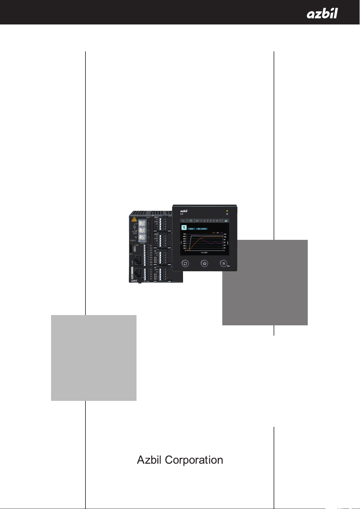
Multi-loop Controller with
Multifunction Display
Model C7G
Installation and
Configuration Manual
Thank you for purchasing an Azbil
Corporation product.
This manual contains information for
ensuring the correct use of this product.
It also provides necessary information
for installation, maintenance, and
troubleshooting.
This manual should be read by those who
design and maintain equipment that uses
this product. Be sure to keep this manual
nearby for handy reference.
Page 2

NOTICE
Be sure that the user receives this manual before the product is used.
Copying or duplicating this user’s manual in part or in whole is forbidden.
The information and specifications in this manual are subject to change
without notice.
Considerable effort has been made to ensure that this manual is free from
inaccuracies and omissions. If you should find an error or omission, please
contact the azbil Group.
In no event is Azbil Corporation liable to anyone for any indirect, special or
consequential damages as a result of using this product.
© 2017-2018 Azbil Corporation. All Rights Reserved.
Page 3

Safety Requirements
To reduce the risk of an electric shock that could cause personal injury,
follow all safety notices in this document.
This symbol warns the user of a potential shock hazard where hazardous
live voltages may be accessible.
Use of this product in a manner not specified by the manufacturer will impair its built-in safety features.
Do not replace any component except as specified by the manufacturer.
All wiring work must comply with local regulations and be carried out by authorized and experienced
personnel.
Make sure to provide a cutoff switch for the power to this device within reach of the operator.
Do not remove blocks except to replace them.
Replacing the MOTOR block (p.11-1) (for information on replacement blocks)
For DC models, connect a Class II power supply unit.
Equipment Ratings
Ingress protection: IP67 (display unit)
AC power
Supply voltage: 100–240 V AC (operating voltage: 85–264 V AC)
Power supply frequency: 50/60 Hz
Power consumption: 25 VA max. 10 W max.
Replacement of the CLOCK block (p.11-1) and
DC power
Supply voltage: 24 V DC (operating voltage: 20.4 to 28.8 V DC)
Power consumption: 12 W max.
Environmental conditions
Do not use this device where there are corrosive gases, or flammable fluids or gases.
Operating temperature: 0 to 50 °C
Operating humidity: 10 to 90 % RH (without condensation)
Vibration: 5 m/s
Overvoltage: Category II (IEC 60364-4-443, IEC 60664-1)
Pollution degree: 2
Installation location: Indoors
Elevation: 2000 m max.
Ventilation space: At least 50 mm above and below the main unit. No space is needed
Equipment Installation
Excluding the supplied power, the I/O common mode voltage with respect to the ground should be
30 Vrms max., 42.4 V peak max., and 60 V DC max.
Standards Compliance
EN 61010-1, EN 61326-1 (for use in industrial locations)
During EMC testing, the reading or output may fluctuate by ±10 % FS.
cULus: UL 61010-1, CSA C22.2 No. 61010-1 (UL-compliant models only)
2
(10 to 60 Hz)
around the display unit.
i
Page 4
Conventions Used in This Manual
The safety precautions explained below aim to prevent injury to you and others, and to prevent property damage.
Warnings are indicated when mishandling this
WARNING
product may result in death or serious injury.
CAUTION
product may result in minor injury or property
damage only.
In describing the product, this manual uses the icons and wording listed below.
Indicates that caution is required in handling.
The indicated action is prohibited.
Be sure to follow the indicated instructions.
Handling Precautions:
Precaution is required in handling.
Cautions are indicated when mishandling this
Note:
:
Indicates information that may be useful.
Indicates an item or page to which the user may refer.
(1) (2) (3):
[XXX] button: Square brackets indicate buttons at the bottom of the display unit or buttons and
[XXX] window,
[XXX]
>> :
Numbers inside parentheses indicate steps in a sequence or parts of an explanation.
messages shown on the display unit screen.
Square brackets indicate a window name, message, or menu, shown on the PC screen.
Indicates the result of an operation, or the status after the operation.
ii
Page 5
Safety Precautions
Do not use this device in an environment with conductive pollution, or with dry nonconductive pollution which can become conductive due to condensation, etc. Otherwise,
problems such as tracking phenomena may damage parts, resulting in fire.
Make sure that the frame ground terminal is properly grounded (100 Ω max.) before
connecting the controller to the measurement target or to external control circuits.
Be sure to check that the device has been correctly wired before turning on the power.
Incorrect wiring of this device may cause device failure and also lead to a dangerous accident.
Before removing, mounting, or wiring the device, be sure to turn off the power to this device
and any connected devices. Otherwise, there is a danger of electric shock.
Do not touch electrically charged parts such as the power terminals. There is a danger of
electric shock.
Do not disassemble this device. There is a danger of electric shock or device failure.
To prevent electrical shock, the main unit of this product must be installed in a location that is
only accessible to people with appropriate knowledge about electrical safety. Install the main
unit inside a control panel that cannot be opened without the use of a key or tool.
WARNING
Also, before touching electrically charged components such as the input terminal block for
AC power, be sure to turn off the power. After checking that the voltage has dropped, work
carefully to prevent electrical shock. Always keep the cover on the power input terminal
block. Otherwise, there is a danger of fire or electric shock.
CAUTION
Use this device within the operating ranges given in the specifications (for temperature,
humidity, voltage, vibration, shock, mounting direction, atmosphere, etc.). Otherwise, there
is a danger of fire or device failure.
Wire this device correctly by using the wiring method, power, and installation method
specified in this user’s manual. Otherwise, there is a danger of fire, electric shock, or device
failure.
Do not allow wire clippings, metal shavings, water, etc., to enter the case of this device. There
is a danger of fire or device failure.
Firmly tighten the terminal screws to the torque listed in the specifications. Insufficient
tightening may cause fire or electric shock.
Do not use unused terminals as relay terminals. There is a danger of fire, electric shock, or
device failure.
If the lithium battery used in this device is packaged together with it (installed) and
transported by air or ship, be sure that it is transported in accordance with the IATA DGR/
IMDG Code.
Do not block the ventilation holes. There is a danger of fire or device failure.
iii
Page 6
CAUTION
Do not operate the buttons or the touch panel with a sharp object (such as a mechanical
pencil tip, etc.). Doing so can cause device failure.
The frame ground terminal of this device is a functional ground. Ground the frame ground
terminal to suppress adverse effects from external noise. Otherwise, malfunction may result.
Be sure that the settings are correct for the sensor type. If the settings are incorrect, the
normal PV will not be measured correctly. In that case a dangerous situation such as constant
100 % control output could occur.
iv
Page 7

Copyright, licenses, and registered trademarks
• Notice on use of licensed software of ARM.
This product uses the software according to the license of ARM in a part of the software. The following contents are based on the license
agreement, which does not prescribe customers’ usage restrictions.
Copyright © 2009 - 2015 ARM LIMITED All rights reserved.
Redistribution and use in source and binary forms, with or without modification, are permitted provided that the following conditions are
met:
- Redistributions of source code must retain the above copyright notice, this list of conditions and the following disclaimer.
- Redistributions in binary form must reproduce the above copyright notice, this list of conditions and the following disclaimer in the
documentation and/or other materials provided with the distribution.
- Neither the name of ARM nor the names of its contributors may be used to endorse or promote products derived from this software
without specific prior written permission.
THIS SOFTWARE IS PROVIDED BY THE COPYRIGHT HOLDERS AND CONTRIBUTORS “AS IS” AND ANY EXPRESS OR IMPLIED WARRANTIES,
INCLUDING, BUT NOT LIMITED TO, THE IMPLIED WARRANTIES OF MERCHANTABILITY AND FITNESS FOR A PARTICULAR PURPOSE ARE
DISCLAIMED. IN NO EVENT SHALL COPYRIGHT HOLDERS AND CONTRIBUTORS BE LIABLE FOR ANY DIRECT, INDIRECT, INCIDENTAL, SPECIAL,
EXEMPLARY, OR CONSEQUENTIAL DAMAGES (INCLUDING, BUT NOT LIMITED TO, PROCUREMENT OF SUBSTITUTE GOODS OR SERVICES;
LOSS OF USE, DATA, OR PROFITS; OR BUSINESS INTERRUPTION) HOWEVER CAUSED AND ON ANY THEORY OF LIABILITY, WHETHER
IN CONTRACT, STRICT LIABILITY, OR TORT (INCLUDING NEGLIGENCE OR OTHERWISE) ARISING IN ANY WAY OUT OF THE USE OF THIS
SOFTWARE, EVEN IF ADVISED OF THE POSSIBILITY OF SUCH DAMAGE.
• Notice regarding use of licensed software of STMicroelectronics.
This product uses the software according to the license of STMicroelectronics in a part of the software. The following contents are based
on the license agreement, which does not prescribe customers’ usage restrictions.
COPYRIGHT© 2014 STMicroelectronics
Redistribution and use in source and binary forms, with or without modification,are permitted provided that the following conditions are
met:
1. Redistributions of source code must retain the above copyright notice,this list of conditions and the following disclaimer.
2. Redistributions in binary form must reproduce the above copyright notice,this list of conditions and the following disclaimer in the
documentation and/or other materials provided with the distribution.
3. Neither the name of STMicroelectronics nor the names of its contributors may be used to endorse or promote products derived from
this software without specific prior written permission.
THIS SOFTWARE IS PROVIDED BY THE COPYRIGHT HOLDERS AND CONTRIBUTORS “AS IS”AND ANY EXPRESS OR IMPLIED WARRANTIES,
INCLUDING, BUT NOT LIMITED TO, THE IMPLIED WARRANTIES OF MERCHANTABILITY AND FITNESS FOR A PARTICULAR PURPOSE ARE
DISCLAIMED. IN NO EVENT SHALL THE COPYRIGHT HOLDER OR CONTRIBUTORS BE LIABLE FOR ANY DIRECT, INDIRECT, INCIDENTAL,
SPECIAL, EXEMPLARY, OR CONSEQUENTIAL DAMAGES (INCLUDING, BUT NOT LIMITED TO, PROCUREMENT OF SUBSTITUTE GOODS
OR SERVICES; LOSS OF USE, DATA, OR PROFITS; OR BUSINESS INTERRUPTION) HOWEVER CAUSED AND ON ANY THEORY OF LIABILITY,
WHETHER IN CONTRACT, STRICT LIABILITY,OR TORT (INCLUDING NEGLIGENCE OR OTHERWISE) ARISING IN ANY WAY OUT OF THE USE OF
THIS SOFTWARE, EVEN IF ADVISED OF THE POSSIBILITY OF SUCH DAMAGE.
• microSD is trademark or registered trademark of SD-3C, LLC in the United States, other countries or both.
• Ethernet is a trademark of Xerox Corporation in the United States.
• ModbusTM is a trademark and the property of Schneider Electric SE, its subsidiaries and affiliated companies.
v
Page 8

Contents
Safety Requirements
Conventions Used in This Manual
Safety Precautions
Copyright, licenses, and registered trademarks
Chapter 1. Overview
1 - 1 Overview
1 - 2 Model No. 1-2
Model Selection Guide 1-2
Optional Parts (Sold Separately) 1-7
1 - 3 Names of Parts and Their Functions 1-8
Display unit 1-8
Main unit 1-8
Integrating bracket (supplied with integrated mounting models) 1-8
1 - 4 Input/output Configuration 1-9
1 - 5 Button Operation 1-11
Screen transitions 1-11
Parameter bank 1-12
Japanese language display 1-16
Monitor and graph screen transitions 1-17
Screen transitions of the user HOME screen 1-21
1 - 6 Operation M odes 1-23
1-1
1-1
Chapter 2. Mounting 2-1
2 - 1 External View and Mounting Dimensions
Standard mounting 2-1
Integrated mounting 2-1
Mounting locations 2-1
2 - 2 Mounting Method 2-2
Standard mounting 2-2
Integrated mounting 2-5
2-1
Chapter 3. Wiring 3-1
3 - 1 Wiring Precautions
Wiring precautions 3-2
3 - 2 Recommended Cables 3-3
3 - 3 Crimp Terminals 3-4
Crimp terminals 3-4
Recommended Ferrules 3-4
3 - 4 Wiring 3-6
Noise suppression measures 3-6
Power input 3-7
Grounding 3-7
3-1
vi
Page 9

DI/DO block (7 digital inputs or outputs, selectable) 3-8
RS-485 (RS-485 communication port) 3-9
Analog input block (analog input) 3-10
Analog input block layout 3-11
Analog output block (current outputs, CT inputs, and VT inputs) 3-12
Voltage pulse output block (voltage pulse outputs and 2 CT inputs) 3-13
DI block (4 digital inputs) 3-14
DO block (4 digital outputs, sink output) 3-14
MOTOR block (motor drive outputs and motor feedback inputs) 3-15
I/O isolation 3-16
USB connection 3-16
Inserting or removing a microSD memory card 3-17
Connecting the LAN cable for Ethernet 3-17
Connecting the cable between the main unit and display unit 3-18
Chapter 4. Functions 4-1
4 - 1 Loop Types
Model numbers and loop types 4-1
Setting the loop type 4-4
4 - 2 AI (Analog Input) 4-6
Range types 4-7
Linear scaling low and high limits 4-7
Setting the linear input unit character 4-7
Filter 4-8
Ratio and bias 4-9
Linearization table group definition 4-9
Number of decimal places for PV 4-9
Sampling cycle 4-10
PV Hold 4-10
Power supply frequency 4-10
4 - 3 Mode 4-12
AUTO/MANUAL mode 4-12
Constant value operation / Pattern operation 4-13
RUN/READY mode 4-14
LSP/RSP mode 4-14
Pattern start number 4-15
READY/RUN/HOLD/END mode 4-15
ADVANCE 4-17
G.SOAK clear 4-18
AT (auto-tuning) stop/start 4-18
4 - 4 Control 4-19
Functional block diagram of PID control 4-19
Functional block diagram of ON/OFF control 4-19
Functional block diagram of heating/cooling control 4-20
Control action 4-20
Heating/cooling control dead zone 4-21
4-1
vii
Page 10

Fixed value output 4-22
Special control output 4-23
When switching to MANUAL mode 4-23
PID control initialization 4-24
PID initial MV 4-24
MV change limit 4-25
PID control 4-25
AT (Auto-tuning) 4-26
SP lag 4-26
ON/OFF control 4-27
4 - 5 AT (Auto-tuning) 4-28
How to start 4-28
How to stop AT 4-28
4 - 6 SP 4-31
Setting the LSP from the 1-loop monitor screen 4-32
Selecting LSP group and RSP from the 1-loop monitor screen 4-32
Number of LSP system groups 4-32
RSP setting 4-32
LSP1 to 8 and RSP 4-33
PID group number 4-33
LSP group No. 4-34
DI assignment for LSP group selection 4-34
SP ramp unit 4-35
SP ramp up and down slopes 4-36
SP low and high limits 4-37
RSP tracking 4-37
4 - 7 Pattern Operation 4-38
Number of patterns 4-39
Time unit for patterns 4-39
Number of segments 4-39
SP/Time 4-39
PID group number 4-41
G.SOAK (guaranteed soak) 4-41
Segment event 4-43
PV start 4-43
Cycle 4-44
Pattern link 4-44
End of operation 4-45
Pattern start number 4-46
Pattern SP increase/decrease change limit 4-47
4 - 8 DI (Digital Input) 4-49
DI/DO configuration 4-49
DI assignment 4-50
4 - 9 Events 4-55
Operation 4-56
Operation type and Loop definition 4-61
Direct/reverse, Standby, and READY mode operation 4-62
Event main setting, event subsetting, hysteresis, delay 4-64
viii
Page 11

4 - 10 DO (Digital Output) 4-65
DI/DO configuration 4-65
DO assignment 4-66
4 - 11 TP (Time Proportioning) Output 4-68
DI/DO configuration 4-69
TP output type 4-69
TP cycle 4-70
TP operation type 4-70
Linearization table group definition 4-71
4 - 12 Analog Output (AO) 4-72
Output range 4-72
Output type 4-72
Loop definition 4-73
Output scaling low and high limits 4-73
Linearization table group definition 4-74
4 - 13 Motor Drive Output (Position Proportional Control) 4-75
Output type 4-75
Control method 4-76
MFB AT (MFB auto-tuning) 4-77
MFB adjustment value 4-78
Dead zone 4-79
Linearization table group definition 4-80
4 - 14 CT (Current Transformer) Input 4-81
Number of turns and number of power wire loops 4-81
CT input display range and current measurement range 4-82
Current measurement and error detection 4-83
Condition for restoring status before measurement 4-88
Timing for updating CT current measurement 4-88
4 - 15 VT (Voltage Transformer) Input 4-89
Primary voltage and secondary voltage 4-89
4 - 16 Linear Approximation 4-90
Linearization by specifying breakpoints 4-90
Linearization by specifying bias 4-91
Example using linear approximation by analog input 4-91
Example using linear approximation for analog output 4-92
When the increase in magnitude of the breakpoints on the A-axis is not in
numerical order 4-94
When two adjacent breakpoints have the same value on the A-axis 4-94
4 - 17 Internal Cascade 4-95
Master/Slave 4-95
Loop Types 4-95
Example: Internal cascade settings 4-96
4 - 18 Logical Operations 4-98
Processing order for logical operations 4-98
Calculation type 4-99
Input assignments A, B, C, and D 4-99
Input bit polarities A, B, C, and D 4-99
Reverse 4-100
ix
Page 12

ON/OFF delay 4-100
4 - 19 CDS (Compact Data Storage) 4-102
Recording cycle/operation type 4-102
Data selection 4-103
Number of data / Data1 to Data40 4-104
Screen during CDS operation 4-106
Files 4-107
Customizing the number of data items and data types 4-111
Setting the date and time by the SLP-C7 4-113
microSD card operations from SLP-C7 4-114
Specifications of older versions 4-115
4 - 20 Health Index 4-116
R value 4-116
Settings 4-116
Operation 4-117
Graph display 4-118
4 - 21 Display Unit Adjustment 4-119
Brightness adjustment 4-119
Position adjustment 4-119
4 - 22 Advanced Loop Type Setting 4-121
Loop types 4-121
Input assignment 4-121
Virtual AI (analog Input) 4-123
Chapter 5. Screens 5-1
5 - 1 Monitor Screen and Graph Screen
Home screen 5-1
1-loop monitor screen 5-10
Pattern operation monitor screen 5-12
Multi-loop graph screen 5-15
1-loop graph screen 5-17
1-loop monitor screen in MANUAL mode 5-18
1-loop monitor screen during AT execution 5-19
1-loop monitor screen when MFB AT is stopped 5-20
1-loop monitor screen during MFB AT 5-21
Screen at key lock 5-22
1-loop monitor screen if there is an alarm 5-23
Block alarm screen 5-24
Function alarm screen 5-25
SP menu screen 5-26
LSP/RSP select screen 5-27
LSP setting change screen 5-28
Mode menu screen 5-30
Mode menu screen (pattern) 5-31
AUTO/MANUAL change screen 5-32
RUN/READY change screen 5-33
5-1
x
Page 13

AT start/stop screen 5-34
HOLD mode change screen 5-35
ADVANCE operation screen 5-36
G.SOAK clear screen 5-37
DI/DO monitor screen 5-38
DI monitor screen 5-39
DO monitor screen 5-40
EV monitor screen 5-41
SEG-EV monitor screen 5-42
5 - 2 Parameter screen 5-43
Parameter bank menu screen 5-43
Parameter item menu screen 5-44
Parameter item setting change screen 5-45
Pattern settings/segment settings 5-46
IP address 5-48
Date and Time 5-50
Firmware Versions 5-52
Chapter 6. Display and Setting Data 6-1
6 - 1 Operation D isplay Data
Home screen 6-1
1-loop monitor screen 6-2
Graph screen 6-5
6 - 2 Parameter Setting Display Data 6-6
SP bank 6-6
EVENT bank 6-7
PID bank 6-7
ANALOG INPUT bank 6-8
Basic action bank 6-9
CONTROL bank 6-12
SP CONFIG bank 6-15
ANALOG OUTPUT bank 6-16
EVENT CONFIG bank 6-17
DI/DO CONFIG bank 6-19
DO configuration bank 6-20
DI bank 6-22
TP (time proportioning) bank 6-24
Logical operation bank 6-27
User-defined bit bank 6-28
User-defined number bank 6-29
User-defined alarm bank 6-30
CT INPUT bank 6-31
VT INPUT bank 6-32
PP (position proportional) bank 6-33
Linearization table bank 6-35
Cascade bank 6-35
6-1
xi
Page 14

Graph bank 6-36
ETHERNET bank 6-36
IP ADDRESS bank 6-37
RS-485 bank 6-37
CDS bank 6-38
HEALTH INDEX bank 6-40
HEALTH INDEX graph 6-41
Date and time bank 6-41
Input assignment bank 6-42
Virtual analog input bank 6-44
6 - 3 Pattern Setting Display Data 6-46
Pattern configuration bank 6-46
Pattern bank 6-47
Segment bank 6-48
6 - 4 Parameter Data for Communication 6-49
Monitor (RAM)/Loop1 to 4 6-49
Monitor/Mode 6-49
Monitor/Operation display (Loop1 to 4) 6-50
Monitor/Operation display (AO-C block) 6-50
Monitor/operation display (V-P block) 6-51
Monitor/Status (DI/DO block) 6-51
Monitor/Status (Events 1 to 16) 6-52
Monitor/Status (other) 6-52
Alarm condition 6-53
Monitor/Position proportional 6-53
Monitor/Pattern mode 6-54
Monitor/Pattern monitor 6-54
Monitor/Segment event 6-55
SP Configuration (LSP group selection) 6-55
User-defined bits (RAM) 6-55
Device info. 6-56
Standard bits 6-56
Standard numerical code 6-56
Chapter 7. Modbus RTU Communication Functions 7-1
7 - 1 Overview of Communications
Features 7-1
Settings 7-2
Communication procedure 7-2
7 - 2 Message Structure 7-3
Message structure 7-3
Command type 7-4
Exception codes 7-4
Amount of data 7-5
7 - 3 Description of Commands 7-6
Multiple data read command (03H) 7-6
xii
7-1
Page 15

Multiple data write command (10H) 7-7
1 data write command (06H) 7-7
7 - 4 Numeric Value Expression 7-9
Hexadecimal 7-9
7 - 5 Send/Receive Timing 7-10
Time specifications for instruction and response messages 7-10
Specifications of RS-485 driver control timing 7-10
Chapter 8. Modbus TCP Communication Functions 8-1
8 - 1 Overview of Communications
Features 8-1
Settings 8-1
Communication procedure 8-2
General TCP/IP socket communication procedure 8-2
8 - 2 Message structure 8-3
Message structure 8-3
Exception code 8-4
Amount of data 8-5
8 - 3 Description of Commands 8-6
Application section 8-6
Multiple data read command (03H) 8-6
Multiple data write command (10H) 8-7
1 data write command (06H) 8-8
8-1
Chapter 9. User-defined Addresses 9-1
9 - 1 Overview of User-defined Addresses
User-defined addresses 9-1
9 - 2 Address Definition Method 9-2
Setting a user-defined address 9-2
Changing the data address display system 9-4
Normal memory area and RAM area 9-4
Precautions when using both the normal memory area and the RAM area for
the same parameter 9-6
Bit fields 9-8
9 - 3 Initial Values of User-Defined Addresses 9-11
9 - 4 Reception M onitoring 9-13
Reception monitoring settings 9-13
9 - 5 Pattern Communication Data 9-15
Data address overview 9-15
Decimal point 9-16
PATTERN COMMUNICATION SETUP 9-16
Pattern communication access procedure 9-17
Data address details 9-18
9-1
xiii
Page 16

Chapter 10. PLC Link Communication 10-1
10 - 1 Data Transfer
Connectible PLCs 10-4
Usable devices 10-5
10 - 2 PLC Link Setting Method 10-6
Common settings 10-6
Transfer settings 10-7
Transfer setting examples 10-8
10 - 3 List of PLC Link Settings 10-12
PLC connection settings 10-12
Transfer settings 10-12
Data settings 10-13
10 - 4 Mitsubishi PLC 10-14
iQ-R series CPU direct connection 10-14
Q series CPU direct connection 10-16
Q series Ethernet interface module 10-19
iQ-F series CPU direct connection 10-22
10-1
Chapter 11. Maintenance and Troubleshooting 11-1
11 - 1 Maintenance and Troubleshooting
Cleaning 11-1
Parts replacement 11-1
Replacement of the CLOCK block 11-1
Replacing the MOTOR block 11-1
11 - 2 Alarm 11-2
Block alarm screen 11-2
Block alarm 11-3
Function alarm screen 11-5
Function alarm 11-6
11 - 3 Display Error 11-7
Display unit does not work. 11-7
Nothing is shown on display unit. 11-7
An error is indicated on the display unit 11-7
The firmware version of the display unit does not match. 11-8
11-1
Chapter 12. DISPOSAL 12-1
Removing the battery for product disposal 12-1
Chapter 13. Specifications 13-1
Specifications 13-1
Input types and ranges 13-12
Input sensor standards 13-13
xiv
Page 17

Chapter 14. Appendix 14-1
14 - 1 Function Block Diagrams
AI (analog input) process block diagram 14-1
SP process / PID process block diagram 14-2
AO (analog output) process block diagram 14-3
TP (time proportioning) output process block diagram 14-4
PP (position proportional) output process block diagram 14-5
14 - 2 Standard Bit Codes and Standard Numerical Codes 14-6
Standard bit codes 14-6
Standard numerical codes 14-8
14 - 3 Precautions for Communication Function 14-10
Examples of operations when using both the normal memory area and RAM
area for the same parameter 14-10
Support start date: September 2016 14-13
14 - 4 Firmware Version History 14-13
Support start date: December 2016 14-15
Support start date: June 2017 14-18
Support start date: August 2017 14-22
Support start date: August 2018 14-26
14 - 5 Abbreviations and Terms 14-32
14-1
xv
Page 18

Page 19

Chapter 1. Overview
1 - 1 Overview
The C7G multi-loop controller with multifunction display (hereafter also called simply "this device") can calculate
diagnostic parameters, known collectively as the health index, that help to predict failure of other equipment,
in addition to calculations for PID (proportional, integral and derivative) control of process variables such as
temperature, pressure, flow rate, pH, and liquid level.
This product consists of a display unit with a 3.5-inch QVGA LCD touch panel, as well as a main unit capable of
controlling up to four loops with an input sampling cycle of 10 ms and an indication accuracy of ± 0.1 % FS.
The display unit and main unit can be installed separately for installation flexibility.
A wide variety of interfaces, including Ethernet, RS-485 serial communication, microSD memory card, micro USB
port, and 7 digital input/outputs are provided as standard features.
Setup, operation, and monitoring can be easily accomplished using the display unit and Smart Loader Package.
This controller is compliant with IEC directives and is CE marked.
1-1
Page 20
Chapter 1. Overview
1 - 2 Model No.
Model Selection Guide
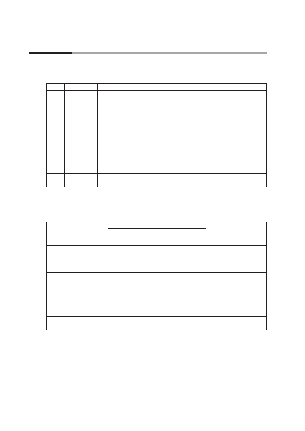
Block name
Symbol Block Name Description
AI Analog input Full multi-range input (thermocouple, RTD, DC current, DC voltage)
V-P Voltage pulse
output
AO-C Analog current
output
HMI2 Additional
display unit
CLOCK Clock function Clock (available for CDS and health index) with a battery
MOTOR Motor drive
output
DI Digital input 4 digital inputs (external power source required)
DO Digital output 4 digital outputs (sink output)
Voltage pulse output (12 V DC)
2 input terminals for the current transformer (CT) for detecting heater burnout,
overcurrent, and short circuits*
Current output (4–20 mA DC / 0–20 mA DC)
Input terminals for the current transformer (CT) for measuring current and the voltage
transformer (VT) for measuring voltage (1 each)*
Connector for the second display unit*
Motor drive outputs (100/200 V AC) (direct (OPEN), reverse (CLOSE))
with motor feedback (MFB) inputs
1
1
2
*1. Current transformer (CT) and voltage transformer (VT) are sold separately.
*2. Additional display unit is sold separately.
Accessories
Qty.
Part name
Main unit 1 1
Display unit 1 1
Standard gasket 1 0 Mounted on the display unit
Gasket with 92 × 92 mm hole 0 1
Display unit mounting screws
(6 mm)
Display unit mounting screw
(10 mm)
Setscrew for temporary
mounting
Integrating bracket 0 1
Integrating cable 0 1
Installation Manual 1 1 Document No. CP-UM-5487JE
Standard (separate)
mounting model
(C7G_4)
5 5 4 screws plus 1 spare
5 0 4 screws plus 1 spare
2 0
Integrated mounting
model
(C7G_3)
Notes
1-2
Page 21
Chapter 1. Overview
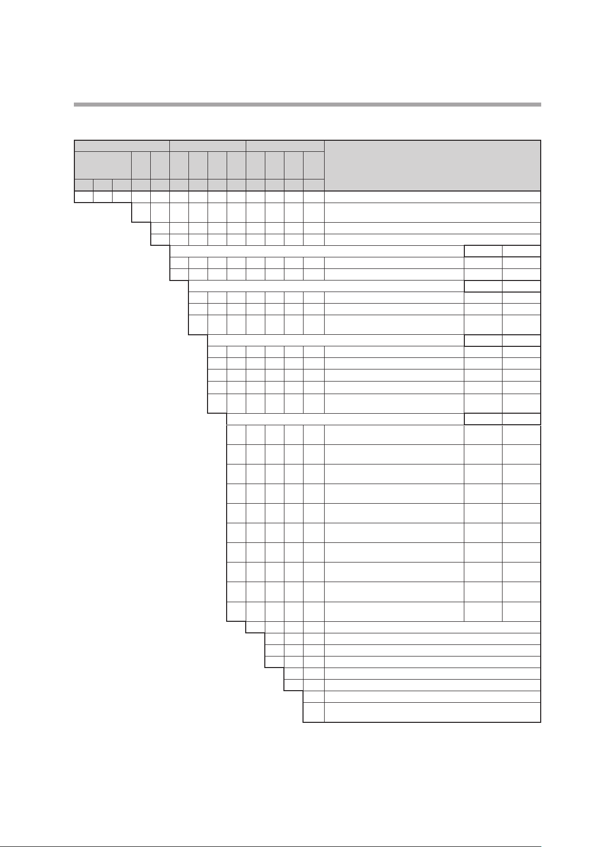
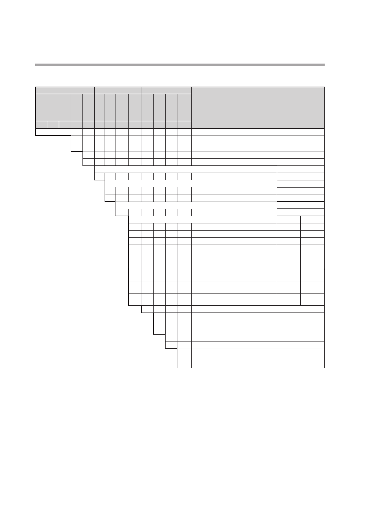
Model C7G (UL-compliant) Example: C7GA411CC0DA0
Main unit I/O Other
Slots
Slots
Slots
Comm.
Size
A3,
B3,
A4
B4
1 2 3 4 5 6 7 8 9 10 11 12 13
C 7 G Multi-loop controller with multifunction display
A Communication (Ethernet, RS-485, USB)
3 Integrated mounting*
4 Standard (separate) mounting
1 PV1 (full-multi) × 1 (No block) AI
2 PV1 (full-multi) + RSP1 (full-multi)*
0 None (No block) (No block)
1 PV2 (full-multi) × 1 (No block) AI
Selectable if the 6th digit of the model
number (slots A3, A4) = 2 ........................→
Selectable if the 8th digit of the model number
(slots A1, A2) = C, V, or F ..........................→
Selectable if the 8th digit of the model number
(slots A1, A2) = C, F, or N .........................→
Selectable if the 8th digit of the model number
(slots A1, A2) = C, V, W, or N ......................→
Selectable if the 8th digit of the model number
(slots A1, A2) = F .................................→
Selectable if the 8th digit of the model number
(slots A1, A2) = W or N ...........................→
Selectable if the 8th digit of the model number
(slots A1, A2) = F or N ............................→
Selectable if the 8th digit of the model number
(slots A1, A2) = C, F, or N .........................→
Selectable if the 8th digit of the model number
(slots A1, A2) = C, V, W, or N ......................→
Selectable if the 8th digit of the model number
(slots A1, A2) = C, F, or N .........................→
Selectable if the 8th digit of the model number
(slots A1, A2) = C, V, W, or N ......................→
2 PV2 (full-multi) + RSP2 (full-multi)*
Slots
A1,
B1, B2Option
A2
C Current output (CT and VT inputs, 1 each) × 1 (No block) AO-C
V Voltage pulse output (2 CT inputs) × 1 (No block) V-P
F Current output (CT and VT inputs, 1 each) × 2 AO-C AO-C
W Voltage pulse output (2 CT inputs) × 2 V-P V-P
N Current output (CT and VT inputs, 1 each) +
0 None (No block) (No block)
C Current output (CT and VT inputs, 1 each) × 1 (No block) AO-C
V Voltage pulse output (2 CT inputs) × 1 (No block) V-P
F Current output (CT and VT inputs, 1 each) × 2 AO-C AO-C
W Voltage pulse output (2 CT inputs) × 2 V-P V-P
N Current output (CT and VT inputs, 1 each) +
G Current output (CT and VT inputs, 1 each) +
H Voltage pulse output (2 CT inputs) + additional
L Current output (CT and VT inputs, 1 each) +
P Voltage pulse output (2 CT inputs) + clock
Add'l
Add'l
proc.
0 None
0 None
D With inspection report
Y With traceability certificate
Special
spec.
support
7 digital input/outputs (sink output, source input)
voltage pulse output (2 CT inputs)
voltage pulse output (2 CT inputs)
additional display unit
display unit
clock (with battery)
(with battery)
A AC power plus CE, KC, GB, and UL compliance
B DC power plus CE, KC, GB, and UL compliance
0 No special support
F Overseas models: switchable between Celsius/Fahrenheit
Do not use these models in Japan.
DescriptionBase model No.
1
Slot A3 Slot A4
2
Slot B3 Slot B4
3
Slot A1 Slot A2
V-P AO-C
Slot B1 Slot B2
V-P AO-C
HMI2 AO-C
HMI2 V-P
CLOCK AO-C
CLOCK V-P
AI AI
AI AI
*1. A rear mounting bracket and a dedicated cable for connecting the display unit are included with the product.
*2. RSP1 can be switched for use as PV3.
*3. RSP2 can be switched for use as PV4.
1-3
Page 22
Chapter 1. Overview
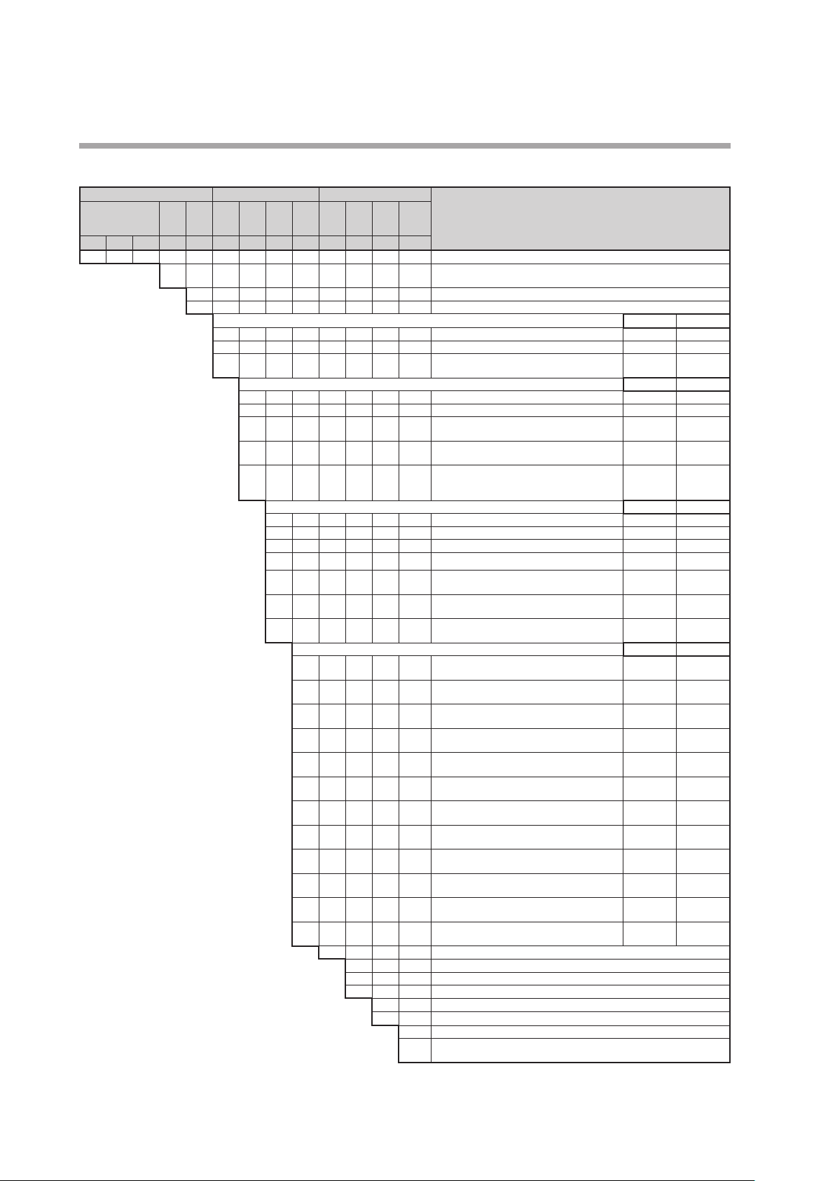
Model C7G (Not UL-compliant) Example: C7GA411CC0D00
Main unit I/O Other
Comm.
1 2 3 4 5 6 7 8 9 10 11 12 13
C 7 G Multi-loop controller with multifunction display
A Communication (Ethernet, RS-485, USB)
Selectable if the 6th digit of the
model number (slots A3, A4) = 2 ..→
Selectable if the 6th digit of the model
number (slots A3, A4) = 2 or A .......→
Selectable if the 9th digit of the
model number (slots B1, B2) = 0, C, V,
F, W, N, G, H, 1, or 2 .................→
Selectable if the 8th digit of the model number
(slots A1, A2) = C, V, F, 1, or 2 .....................→
Selectable if the 8th digit of the model number
(slots A1, A2) = C, F, N, or 1 .......................→
Selectable if the 8th digit of the model number
(slots A1, A2) = C, V, W, N, 1, or 2 .................→
Selectable if the 8th digit of the model number
(slots A1, A2) = F .................................→
Selectable if the 8th digit of the model number
(slots A1, A2) = W or N ...........................→
Selectable if the 8th digit of the model number
(slots A1, A2) = F or N ............................→
Selectable if the 8th digit of the model number
(slots A1, A2) = C, F, N, or 1 .......................→
Selectable if the 8th digit of the model number
(slots A1, A2) = C, V, W, N, 1, or 2 .................→
Selectable if the 8th digit of the model number
(slots A1, A2) = C, F, N, or 1 .......................→
Selectable if the 8th digit of the model number
(slots A1, A2) = C, V, W, N, 1, or 2 .................→
Selectable if the 8th digit of the model number
(slots A1, A2) = F, N, or 1. . . . . . . . . . . . . . . . . . . . . . . . . . →
Selectable if the 8th digit of the model number
(slots A1, A2) = W, N, 1, or 2 ......................→
Slots
Slots
Slots
Size
A3,
B3,
A4
B4
3 Integrated mounting*
4 Standard (separate) mounting
1 PV1 (full-multi) × 1 (No block) AI
2 PV1 (full-multi) + RSP1 (full-multi)*
A PV1 (full-multi) + 4 digital inputs (external
0 None (No block) (No block)
1 PV2 (full-multi) × 1 (No block) AI
2 PV2 (full-multi) + RSP2 (full-multi)*
A PV1 (full-multi) + 4 digital inputs (external
B PV1 (full-multi) + clock (with battery) CLOCK AI
Slots
A1,
B1, B2Option
A2
C Current output (CT and VT inputs, 1 each) × 1 (No block) AO-C
V Voltage pulse output (2 CT inputs) × 1 (No block) V-P
F Current output (CT and VT inputs, 1 each) × 2 AO-C AO-C
W Voltage pulse output (2 CT inputs) × 2 V-P V-P
N Current output (CT and VT inputs, 1 each) +
1 Current output (CT and VT inputs, 1 each) + 4
2 Voltage pulse output (2 CT inputs) × 4 digital
0 None (No block) (No block)
C Current output (CT and VT inputs, 1 each) × 1 (No block) AO-C
V Voltage pulse output (2 CT inputs) × 1 (No block) V-P
F Current output (CT and VT inputs, 1 each) × 2 AO-C AO-C
W Voltage pulse output (2 CT inputs) × 2 V-P V-P
N Current output (CT and VT inputs, 1 each) +
G Current output (CT and VT inputs, 1 each) +
H Voltage pulse output (2 CT inputs) +
L Current output (CT and VT inputs, 1 each) +
P Voltage pulse output (2 CT inputs) + clock
1 Current output (CT and VT inputs, 1 each) × 4
2 Voltage pulse output (2 CT inputs) × 4 digital
Add'l
Add'l
proc.
0 None
0 None
D With inspection report
Y With traceability certificate
Special
spec.
support
7 digital input/outputs (sink output, source input)
power source required)
power source required)
voltage pulse output (2 CT inputs)
digital outputs (sink output)
outputs (sink output)
voltage pulse output (2 CT inputs)
additional display unit
additional display unit
clock (with battery)
(with battery)
digital outputs (sink output)
outputs (sink output)
0 AC power plus CE, KC, and GB compliance
D DC power plus CE, KC, and GB compliance
0 No special support
F Overseas models: switchable between Celsius/Fahrenheit
Do not use these models in Japan.
DescriptionBase model No.
1
2
3
Slot A3 Slot A4
AI AI
DI AI
Slot B3 Slot B4
AI AI
DI AI
Slot A1 Slot A2
V-P AO-C
DO AO-C
DO V-P
Slot B1 Slot B2
V-P AO-C
HMI2 AO-C
HMI2 V-P
CLOCK AO-C
CLOCK V-P
DO AO-C
DO V-P
*1. A rear mounting bracket and a dedicated cable for connecting the display unit are included with the product.
*2. RSP1 can be switched for use as PV3.
*3. RSP2 can be switched for use as PV4.
1-4
Page 23
Chapter 1. Overview
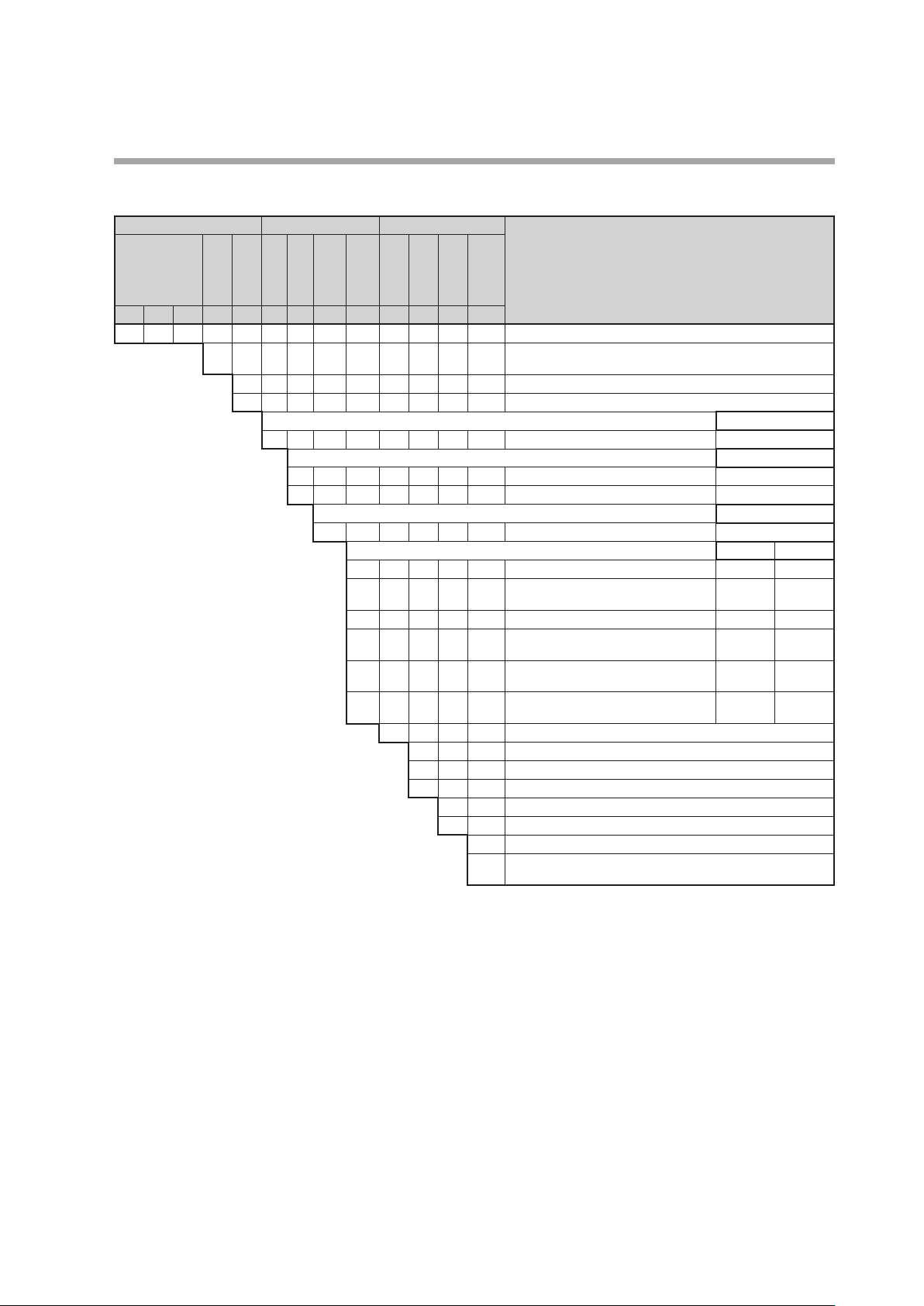
Model C7G with MOTOR Block (UL-compliant) Example: C7GA411MC0DA0
Main unit I/O Other
Slots
Slots
Comm.
1 2 3 4 5 6 7 8 9 10 11 12 13
C 7 G Multi-loop controller with multifunction display
A Communication (Ethernet, RS-485, USB)
Slot A4Slot
Size
3 Integrating kit included*
4 Standard mounting
1 PV1 (full-multi) × 1 AI
A2,
A1,
A3,
B4
0 None
1 PV2 (full-multi) × 1*
B1
B2,
B3
M Motor drive output (with MFB input) MOTOR
0 None
C Current output (CT and VT inputs, 1 each)
V Voltage pulse output (2 CT inputs) × 1 V-P
N Current output (CT and VT inputs, 1 each)
G Current output (CT and VT inputs, 1 each)
L Current output (CT and VT inputs, 1 each)
Add'l
Add'l
Option
proc.
0 None
0 None
D With inspection report
Y With traceability certificate
Special
spec.
support
7 digital input/outputs (sink output, source input)
× 1
+ voltage pulse output (2 CT inputs)
+ additional display unit
+ clock (with battery)
A AC power plus CE, KC, GB, and UL compliance
B DC power plus CE, KC, GB, and UL compliance
0 No special support
F Overseas models: switchable between Celsius/Fahrenheit
Do not use these models in Japan.
DescriptionBase model No.
1
2
Slot A4
Slot B4
(No block)
Slots A2, A3, B2, B3
Slot A1 Slot B1
(No block) (No block)
AO-C
AO-C V-P
AO-C HMI2
AO-C CLOCK
AI
(No block)
(No block)
*1. A rear mounting bracket and a dedicated cable for connecting the display unit are included with the product.
*2. PV2 can be switched for use as RSP1.
1-5
Page 24
Chapter 1. Overview
Model C7G with MOTOR Block (Not UL-compliant) Example: C7GA411MC0D00
Main unit I/O Other
Slots
A2,
Comm.
1 2 3 4 5 6 7 8 9 10 11 12 13
C 7 G Multi-loop controller with multifunction display
A Communication (Ethernet, RS-485, USB)
Slot A4Slot
Size
3 Integrating kit included*
4 Standard mounting
B4
1 PV1 (full-multi) × 1 AI
0 None (No block)
1 PV2 (full-multi) × 1*
Slots
A3,
A1,
B2,
B1
B3
M Motor drive output (with MFB input) MOTOR
0 None (No block) (No block)
C Current output (CT and VT inputs, 1 each) × 1 AO-C (No block)
V Voltage pulse output (2 CT inputs) × 1 V-P (No block)
N Current output (CT and VT inputs, 1 each) +
G Current output (CT and VT inputs, 1 each) +
L Current output (CT and VT inputs, 1 each) +
1 Current output (CT and VT inputs, 1 each) × 4
4 4 digital outputs (sink output) + clock (with
Add'l
Add'l
Option
proc.
0 None
0 None
D With inspection report
Y With traceability certificate
Special
spec.
support
7 digital input/outputs (sink output, source input)
voltage pulse output (2 CT inputs)
additional display unit
clock (with battery)
digital outputs (sink output)
battery)
0 AC power plus CE, KC, and GB compliance
D DC power plus CE, KC, and GB compliance
0 No special support
F Overseas models: switchable between Celsius/Fahrenheit
Do not use these models in Japan.
DescriptionBase model No.
1
2
Slots A2, A3, B2, B3
Slot A1 Slot B1
AO-C V-P
AO-C HMI2
AO-C CLOCK
AO-C DO
Slot A4
Slot B4
AI
DO CLOCK
*1. A rear mounting bracket and a dedicated cable for connecting the display unit are included with the product.
*2. PV2 can be switched for use as RSP1.
1-6
Page 25
Chapter 1. Overview
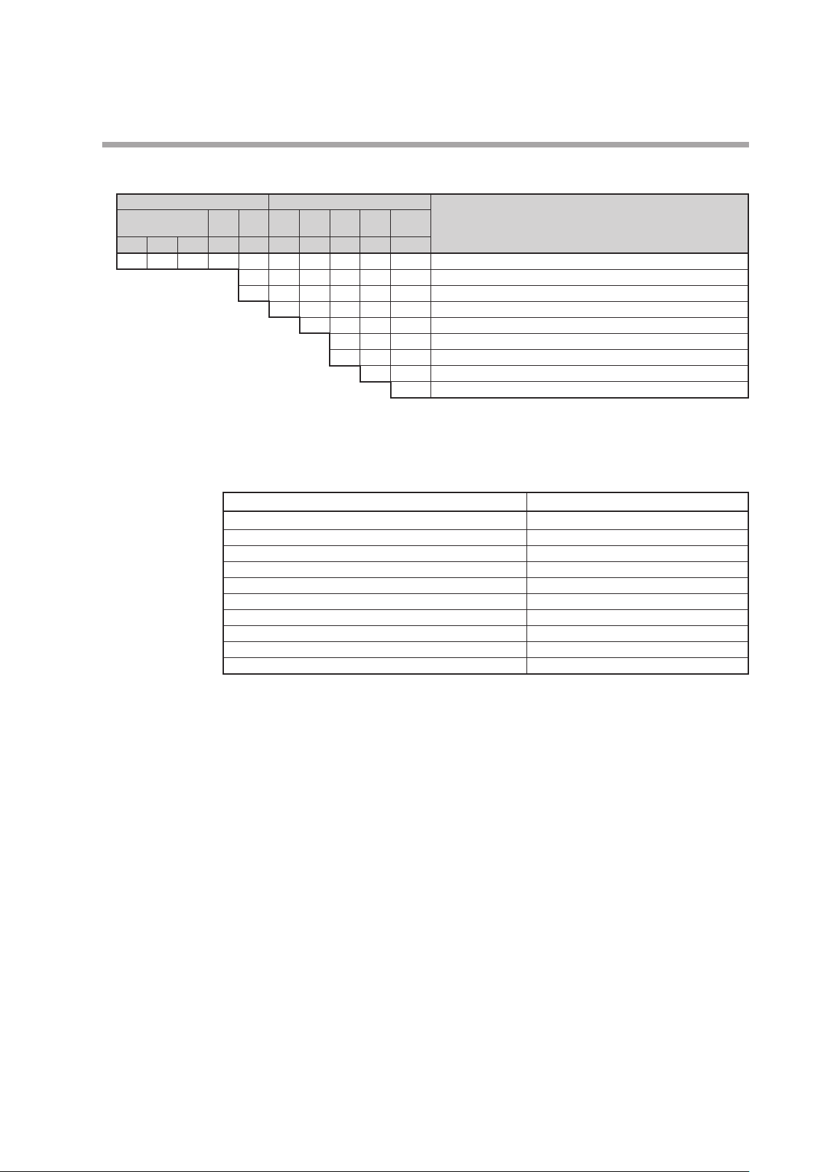
C7D Additional Display Unit Example: C7D-400D00
Main unit Other
Option 1Option 2Add'l
1 2 3 4 5 6 7 8 9 10
C 7 D - Additional display unit for multi-loop controller with multifunction display
3 Integrated mounting*
4 Standard mounting
0 English, Japanese
0 None
Add'l
proc.
0 None
D With inspection report
Special
spec.
support
0 CE marking, KC, GB
0 No special support
DescriptionBase model No. - Size
* Rear mounting bracket included.
Optional Parts (Sold Separately)
SLP-C7 Smart Loader Package (free version)*
SLP-C7 Smart Loader Package (paid version) SLP-C7-J91
Power terminal covers (10) 81447704-001 (available soon)
Integrating kit 84503167-001 (available soon)
MicroSD card (replacement) 84502552-001 (available soon)
Clock block (replacement) 84501420-001 (available soon)
MOTOR Block (replacement) 84501421-001 (available soon)
Current transformer (5.8 mm in diameter) QN206A
Current transformer (12 mm in diameter) QN212A
Voltage transformer (for 200 V AC) 81406725-003
Part name Model No.
SLP-C7FJ91
1-7
Page 26
Chapter 1. Overview
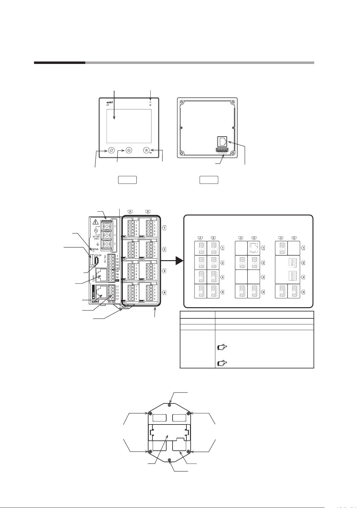
1 - 3 Names of Parts and Their Functions
Display unit
Main unit
Power supply terminal block
(with cover)
Status indicator
Connector for
microSD* memory card
LCD touch panel
Change button
Power indicator (green for normal status)
Home button
Front
DI/DO terminal block
Menu button
Top
Terminal block
Back
AO-C AO-CAO-CAO-CAO-C
AO-C
Main unit connector
Block diagram examples
C7G_ _ 11CG_ _ _ _ C7G_ _ 11MC_ _ _ _ C7G_ _ 22FF_ _ _ _
HMI2
HMI2
AO-CAO-C
AO-CAO-C
MicroUSB
(TYPE-A/B)
LAN connector
Display connector
RS-485 terminal block
DIN rail holding tab
*
microSD is trademark or registered
trademark of SD-3C, LLC in the
United States, other countries or both.
IO slot
AI
AI
AI
AI
AI
AI
AI
AI
Status indicator Status
Off Not energized
Lit green Normal operation
Lit red
Malfunction
To check an alarm shown on the display,
11 - 2 Alarm (p.11-2)
If a display unit error occurs,
11 - 3 Display Error (p.11-7)
Integrating bracket (supplied with integrated mounting models)
Control panel mounting screw
(2 locations)
Display unit mounting hole
(4 locations)
Display unit mounting hole
(4 locations)
AO-CAO-C
AO-CAO-C
AI
AI AIAI AIAI
AI
AI
MOTORMOTOR
1-8
Main unit mounting rail
Wiring hole
Control panel mounting screw
(2 locations)
Page 27
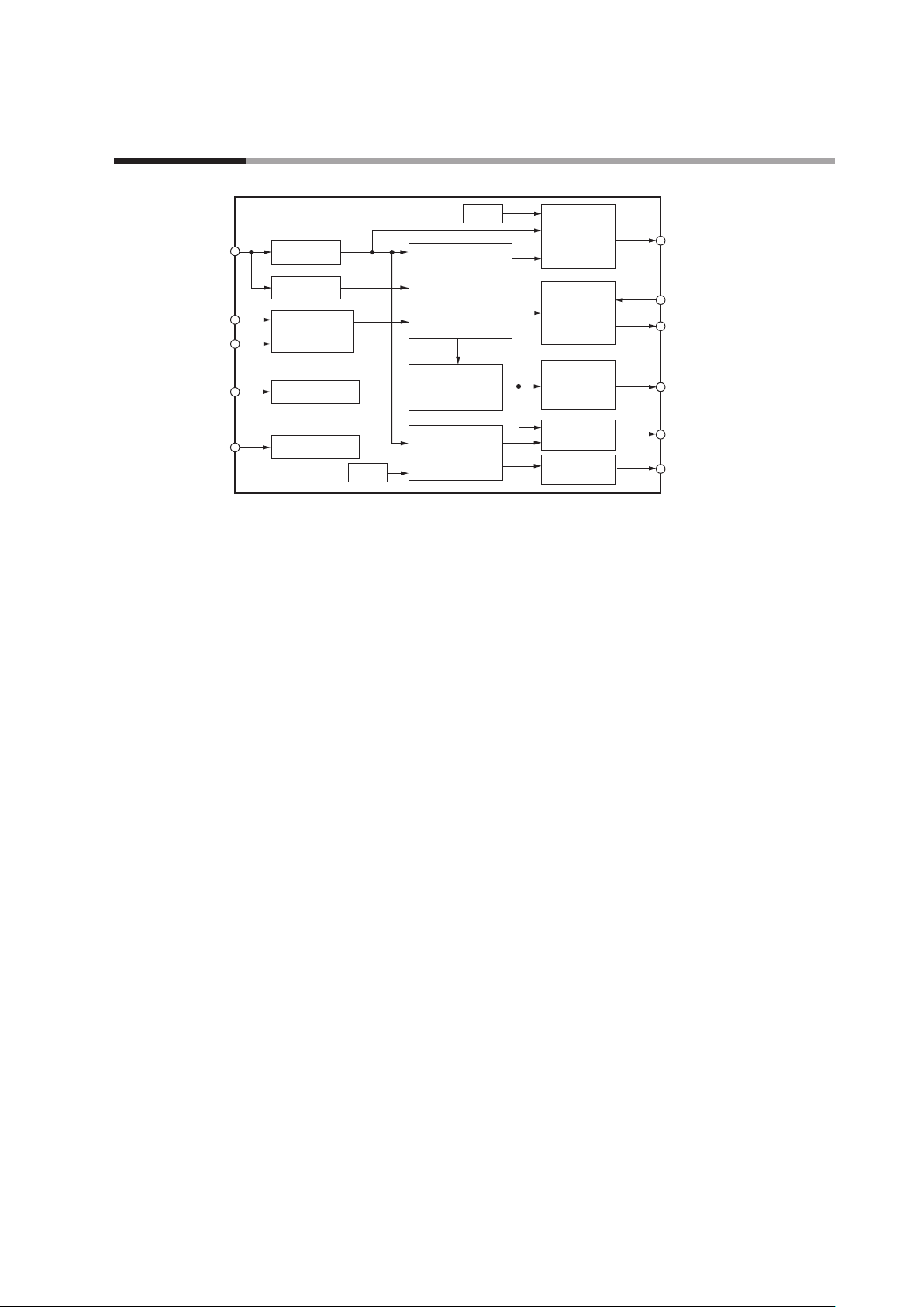
1 - 4 Input/output Configuration
Chapter 1. Overview
Analog input 1 to 4 *
Digital input 1 to 7 *
Digital input 1 to 8 *
CT input 1 to 8 *
VT input 1 to 4 *
*1. There are 7 digital inputs (DI) or outputs (DO) in total. Depending on the setting, they can be switched between DI and DO.
*2. There are from 1 to 4 analog inputs, depending on the model number.
*3. There are from 0 to 4 analog output and VT input points, a total of 4, depending on the model number.
*4. There are from 0 to 8 CT input points, depending on the model number.
*5. There are from 0 to 4 voltage pulse output points, depending on the model number.
*6. There is 0 or 1 set of motor drive outputs (OPEN, CLOSE) and MFB input, depending on the model number.
*7. There are from 1 to 4 control loops, depending on the number of analog inputs and the loop type settings.
*8. There are from 0 to 8 digital inputs, selectable by model number, in addition to the digital inputs described in *1.
*9. There are from 0 to 8 digital outputs, selectable by model number, in addition to the digital outputs described in *1.
Other
2
1
8
4
3
PV process
RSP process
Digital
input process
CT input process
VT input process
Other
Control process*
(PID control,
ON/OFF control)
Internal cascade
control,
Pattern operation)
TP
(time proportioning)
output process
Event process
7
Analog
output
process
Motor drive
output
process
Voltage pulse
output
process
Digital output
process
Digital output
process
Analog output 1 to 4
(Output by scaling the MV,
PV, and other using the
current output.)*
MFB
(motor feedback) input *
Motor drive output
(OPEN, CLOSE) *
Voltage pulse outputs
1 to 4
(TP output) *
Digital output 1 to 7 *
Digital output 1 to 8 *
3
6
5
1
9
6
Analog input (block positions: A4, B4, A3, B3)
The PV can be measured by selecting the sensor type or range. For DC voltage
and DC current, PV and RSP scaling can be set. The input from a thermocouple
or resistance temperature detector can be used as the RSP. Linear approximation is
available.
Analog output (AO-C) (block positions: A2, B2, A1, B1)
The scaled MV can be output as current. Additionally, when PV, SP, or deviation is
selected for the output type, these values can also be scaled and output as current.
Linear approximation is available.
Voltage pulse output (V-P) (block positions: A2, B2, A1, B1)
The time proportioning output function set using the TP (time proportioning)
bank can be used. Linear approximation is available.
Motor drive output (MOTOR) (block position: B2)
The motor drive output function set using the PP (position proportioning) bank
can be used. Linear approximation is available.
Digital input (DI)
Change functions set using the DI bank, such as mode change, or SP group change,
can be used.
1-9
Page 28

Chapter 1. Overview
Digital output (DO)
Output functions such as event output that are set using the DO bank, or the time
proportioning output function set using the TP (time proportioning) bank, can be
used. Linear approximation is available for time proportioning output.
CT (current transformer) input (block positions: A2, B2, A1, B1)
The current can be measured by the input from the CT. The control loop that
displays CT input can be set in the basic action bank.
VT (voltage transformer) input (block positions: A2, B2, A1, B1)
The voltage can be measured by the input from the VT. The control loop that
displays VT input can be set in the basic action bank. The resistance of the actuators
(heaters) calculated from the CT input and VT input can also be displayed in the
same control loop as VT input.
1-10
Page 29
Chapter 1. Overview
1 - 5 Button Operation
Various kinds of data can be displayed or set using the buttons on the display unit screen and the buttons on the
lower section of the display unit screen.
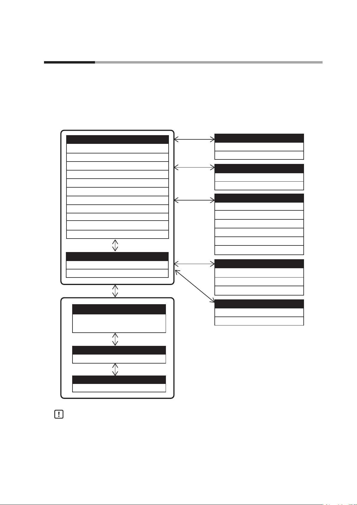
Screen transitions
When the power is turned on, the monitor screen is displayed. Use the buttons on
the monitor screen or graph screen to switch between screens.
Monitor screen
PV, SP, MV, MV bar graph
PV, MV (when in MANUAL mode)
PV, SP, MV, Cool MV, Heat MV (when in heating and cooling control)
PV, SP, MV, pattern time (in pattern operation)
PV, SP, MV, segment time (in pattern operation)
PV, SP, MV, number of cycles, remaining cycles (in pattern operation)
PV、SP、MV、CT、VT(AO-C block
PV、SP、MV
PV、SP、MV、CT1、CT2(V-P block
PV、SP、MV、MFB(MOTOR block
PV、SP、MV、AT progress graph (during AT)
Graph screen
PV, SP, MV graph
PV graph for 2 to 4 loops
、resistance(
Parameter bank menu
Displays the SP, event, PID, and other
parameter banks.
AO-C block
)
)
)
)
Alarm
Block alarm
Function alarm
SP change
LSP group, RSP select
LSP value change
Mode menu
AUTO/MANUAL
RUN/READY
AT start
HOLD ON/OFF (in pattern operation)
ADVANCE (in pattern operation)
G.SOAK clear (in pattern operation)
DI/DO monitor
ON/OFF status of DI, DO
ON/OFF status of events
ON/OFF status of segment events (in pattern operation)
Touch panel position adjust
Touch panel adjust
Touch panel test
Parameter item menu
Displays the items in the parameter bank.
Parameter item setting
Set value can be input using the numeric keypad.
Handling Precautions
• The figure above shows only the major screen transitions. Many screen
transitions are not shown.
• Do not press two or more locations on the touch panel at the same time.
Doing so may cause an error.
• If the firmware version of the MAIN block is earlier than 6.x.x (where x stands
for any number), the screen for pattern operation and the screen showing the
ON/OFF status of events and segment events cannot be displayed.
1-11
Page 30

Chapter 1. Overview
Parameter bank
SP
EVENT
PID
ANALOG INPUT
BASIC ACTION
The order of the parameter banks and parameter items is shown by the tree
structure below.
Parameter bank Parameter item
SP values of LSP1 to LSP8, RSP for loops 1 to 4
PID group number of LSP1 to LSP8, RSP for loops 1 to 4
Main setting for event groups 1 to 16
Sub-setting for event groups 1 to 16
Hysteresis for event groups 1 to 16
ON-delay time for event groups 1 to 16
OFF-delay time for event groups 1 to 16
P (Proportional band) of PID groups 1 to 8 for loops 1 to 4
I (Integral time) of PID groups 1 to 8 for loops 1 to 4
D (Derivative time) of PID groups 1 to 8 for loops 1 to 4
RE (Manual reset) of PID groups 1 to 8 for loops 1 to 4
OL (MV low limit) of PID groups 1 to 8 for loops 1 to 4
OH (MV high limit) of PID groups 1 to 8 for loops 1 to 4
Cooling-use proportional band of PID groups 1 to 8 for
loops 1 to 4
Cooling-use cumulative time of PID groups 1 to 8 for loops
1 to 4
Cooling-use derivative time of PID groups 1 to 8 for loops 1 to 4
Cooling-use MV low limit of PID groups 1 to 8 for loops 1 to 4
Cooling-use MV high limit of PID groups 1 to 8 for loops 1 to 4
Range type of blocks A4, B4, A3, and B3
Linear scaling low limit of blocks A4, B4, A3, and B3
Linear scaling high limit of blocks A4, B4, A3, and B3
Filter of blocks A4, B4, A3, and B3
Ratio of blocks A4, B4, A3, and B3
Bias of blocks A4, B4, A3, and B3
Linearization table group definition of blocks A4, B4, A3, and
B3
Sampling cycle
Power supply frequency
Time unit of patterns
HOME screen layout
Run/Ready at startup for loops 1 to 4
No. of decimal places for PV 1 to 4
Display loop for A2/B2/A1/B1 block input
HOME screen setting for loops 1 to 4
Display intensity
Display language
Engineering mode
1-12
Page 31

Parameter bank Parameter item
CONTROL
SP CONFIG
ANALOG OUTPUT
EVENT CONFIG
DI/DO CONFIG
DO CONFIG
DI
Chapter 1. Overview
Control action for loops 1 to 4
Differential for ON/OFF control for loops 1 to 4
Heating/cooling control dead zone for loops 1 to 4
PID initial MV for loops 1 to 4
PID initialization for loops 1 to 4
Type of change to MANUAL for loops 1 to 4
Preset MANUAL value for loops 1 to 4
MV increase change limit for loops 1 to 4
MV decrease change limit for loops 1 to 4
MV low limit during AT for loops 1 to 4
MV high limit during AT for loops 1 to 4
SP lag factor for loops 1 to 4
READY MV for loops 1 to 4
Output at READY (heat) for loops 1 to 4
Output at READY (cool) for loops 1 to 4
MV select as PV error for loops 1 to 4
MV value as PV error for loops 1 to 4
Fixed-value output 1 to 8 for loops 1 to 4
SP low limit for loops 1 to 4
SP high limit for loops 1 to 4
SP ramp unit for loops 1 to 4
LSP ramp up slope for loops 1 to 4
LSP ramp down slope for loops 1 to 4
RSP tracking for loops 1 to 4
Number of LSP groups for loops 1 to 4
Output range of blocks A2, B2, A1, and B1
Output type of blocks A2, B2, A1, and B1
Loop definition of blocks A2, B2, A1, and B1
Output scaling low limit of blocks A2, B2, A1, and B1
Output scaling high limit of blocks A2, B2, A1, and B1
Linearization table group definition of blocks A2, B2, A1, and
B1
Operation type for event groups 1 to 16
Loop definition for event groups 1 to 16
Direct/reverse for event groups 1 to 16
Standby for event groups 1 to 16
READY mode operation for event group 1 to 16
Operation type of DI/DO 1 to 7
Operation type of DO groups 1 to 7 of DI/DO
Operation type of DO groups 1 to 4 of blocks A1 and B1
Operation type of DI groups 1 to 32
Input type of DI groups 1 to 32
Loop definition of DI groups 1 to 32
1-13
Page 32

Chapter 1. Overview
TP
LOGICAL OPERATION
USER-DEFINED BIT
USER-DEFINED VALUE
USER-DEFINED ALARM
CT
VT
PP (POSITION PROPORTIONAL)
Parameter bank Parameter item
TP output type of DO groups 4 to 7 and blocks A2, B2, A1,
and B1
TP output cycle of DO groups 4 to 7 and blocks A2, B2, A1,
and B1
TP operation type of DO groups 4 to 7 and blocks A2, B2, A1,
and B1
Linearization table group definition of DO groups 4 to 7 and
blocks A2, B2, A1, and B1
Calculation type of logical operations 1 to 32
Input assignments A to D of logical operations 1 to 32
Input bit attributes A to D of logical operations 1 to 32
ON-delay time of logical operations 1 to 32
OFF-delay time of logical operations 1 to 32
Reversal of logical operations 1 to 32
User-defined bits 1 to 16
User-defined values 1 to 16
Assignments 1 to 4 of user-defined alarms 1 to 4
Loop specification for user-defined alarms 1 to 4
Number of turns of blocks A2, B2, A1, and B1
Number of power wire loops of blocks A2, B2, A1, and B1
CT operation of blocks A2, B2, A1, and B1
CT measurement waiting time of blocks A2, B2, A1, and B1
Heater burnout detection current value of blocks A2, B2, A1,
and B1
Minimum current defined as overcurrent of blocks A2, B2,
A1, and B1
Minimum current defined as short circuit of blocks A2, B2,
A1, and B1
Hysteresis of blocks A2, B2, A1, and B1
Delay time of blocks A2, B2, A1, and B1
Condition for restoring status before measurement of blocks
A2, B2, A1, and B1
Primary voltage of blocks A2, B2, A1, and B1
Secondary voltage of blocks A2, B2, A1, and B1
Output type
Control method selection
Dead zone
Auto-tuning
Fully closed MFB count
Fully open MFB count
Full opening time
Linearization table group definition
1-14
Page 33

Parameter bank Parameter item
LINEARIZATION TABLE
CASCADE
PATTERN CONFIG
PATTERN
SEGMENT
GRAPH
ETHERNET
IP ADDRESS
RS-485
CDS
HEALTH INDEX
HEALTH INDEX GRAPH
Chapter 1. Overview
Operation type of linearization table groups 1 to 8
10 break points of linearization table groups 1 to 8
Scaling method
Scaling low limit
Scaling high limit
Filter
Pattern start number for loops 1 to 4
Pattern start number low limit for loops 1 to 4
Pattern start number high limit for loops 1 to 4
PTN SP increase change limit for loops 1 to 4
PTN SP decrease change limit for loops 1 to 4
Number of segments of patterns 1 to 16
G.SOAK time of patterns 1 to 16
PV start of patterns 1 to 16
Cycle of patterns 1 to 16
Pattern link of patterns 1 to 16
End of operation of patterns 1 to 16
SP of segments 1 to 16 of patterns 1 to 16
Time of segments 1 to 16 of patterns 1 to 16
PID Group of segments 1 to 16 of patterns 1 to 16
G.SOAK type of segments 1 to 16 of patterns 1 to 16
G.SOAK width of segments 1 to 16 of patterns 1 to 16
Segment event in segments 1 to 16 of patterns 1 to 16
Multi-loop recording cycle for loops 1 to 4
Graph scaling low limit for loops 1 to 4
Graph scaling high limit for loops 1 to 4
Modbus/TCP port number
IP address
Subnet mask
Default gateway
Station address
Transmission speed
Data type (parity)
Data type (stop bits)
Minimum response time
Recording cycle
Operation type
Operation type for loops 1 to 4
R value scale for loops 1 to 4
Ideal data for loops 1 to 4
Deviation low limit for loops 1 to 4
Deviation high limit for loops 1 to 4
The 10 latest specific R value graph for loops 1 to 4
1-15
Page 34

Chapter 1. Overview
DATE TIME
INPUT ASSIGNMENT
VIRTUAL ANALOG INPUT
FIRMWARE VERSION
Parameter bank Parameter item
Year, month, day, hour, minutes, and seconds
PV assignments for loops 1 to 4
RSP assignment for loops 1 to 4
Assignment range low limit for loops 1 to 4
Assignment range high limit for loops 1 to 4
Virtual AI assignment of virtual AI 1 to 4
Filter of virtual AI 1 to 4
Ratio of virtual AI 1 to 4
Bias of virtual AI 1 to 4
Linearization table group definition of virtual AI 1 to 4
Version of MAIN block
Version of HMI block (display unit)
Version of DI/DO block
Version of RS-485 block
Version of blocks A1 to A4
Version of blocks B1 to A4
(Including additional display unit and CLOCK block)
Japanese language display
If the "Language indication" setting of the basic action bank is set to "1: Japanese,"
the banks, items, and descriptions displayed on the parameter setting screen and
some of the content on the mode change screen will appear in Japanese. The default
setting for "Language indication" is "0: English."
1-16
Page 35

Monitor and graph screen transitions
For 1 loop
Graph icon Numeric icon
Power-on
1-loop monitor
screen
(LOOP1)
1-loop graph
screen
(LOOP1)
Chapter 1. Overview
Home button
The home screen is the
1-loop monitor screen.
1-17
Page 36

Chapter 1. Overview
For 2 loops
Power-on
Home button
The home screen is the multi-loop monitor screen.
Touch the display of each loop.
Multi-loop
monitor screen
(LOOP1 to 2)
Graph icon Numeric icon
Touch the PV No. of each loop.
Multi-loop graph
screen
(LOOP1 to 2)
1-loop monitor
screen
(LOOP1)
Change button
1-loop graph
screen
(LOOP1)
Change button
1-loop monitor
1-loop graph
screen
(LOOP2)
screen
(LOOP2)
1-18
Handling Precautions
• The screen transitions when the loop type is internal cascade are identical to
those for 2 loops.
• The screen set by the user can be displayed when the power is turned ON or
the home button is pressed. Screen transitions of the user HOME screen
(p.1-21)
Page 37

For 3 loops
Chapter 1. Overview
Power-on
Home button
The home screen is the multi-loop monitor screen.
Touch the display of each loop.
Multi-loop
monitor screen
(LOOP1 to 3)
Graph icon Numeric icon
Touch the PV No. of each loop.
Multi-loop graph
screen
(LOOP1 to 3)
1-loop monitor
screen
(LOOP1)
1-loop graph
screen
(LOOP1)
1-loop monitor
screen
(LOOP2)
Change button
1-loop graph
screen
(LOOP2)
Change button
1-loop monitor
screen
(LOOP3)
1-loop graph
screen
(LOOP3)
Handling Precautions
• The screen transitions when the loop type is "Internal cascade + 1 loop" are
identical to those for 3 loops.
• The screen set by the user can be displayed when the power is turned ON or
the home button is pressed. Screen transitions of the user HOME screen
(p.1-21)
1-19
Page 38

Chapter 1. Overview
For 4 loops
Power-on
Touch the display of each loop.
Home button
The home screen is the multi-loop monitor screen.
Multi-loop
monitor screen
(LOOP1 to 4)
Touch the PV No. of each loop.
Multi-loop graph
screen
(LOOP1 to 4)
1-loop monitor
screen
(LOOP1)
Graph icon Numeric icon
1-loop graph
screen
(LOOP1)
1-loop monitor
screen
(LOOP2)
Change button
1-loop graph
screen
(LOOP2)
Change button
1-loop monitor
1-loop graph
screen
(LOOP3)
screen
(LOOP3)
1-loop monitor
screen
(LOOP4)
1-loop graph
screen
(LOOP4)
1-20
Handling Precautions
• The screen transitions when the loop type is "Internal cascade +2 loops" are
identical to those for 3 loops.
• The screen set by the user can be displayed when the power is turned ON or
the home button is pressed. Screen transitions of the user HOME screen
(p.1-21)
Page 39

Screen transitions of the user HOME screen
From the loops set to be used in the loop type setting, enable the loop to be
displayed on the user HOME screen with the following settings.
Item (bank) Display Description Initial value
Loop1 HOME screen setting
(Basic action bank)
MENU>BasicAction
Loop1 HOME screen setting
0: Disabled
1: Enabled
Chapter 1. Overview
0
Power-on
User home
screen
(LOOP1 to 2)
Loop2 HOME screen setting
(Basic action bank)
Loop3 HOME screen setting
(Basic action bank)
Loop4 HOME screen setting
(Basic action bank)
The user HOME screen is displayed only when the power is turned ON or the
home button is pressed.
For example, if the loop type is set to 4 loops and Loop 1 and Loop 2 are selected for
display on the user HOME screen, the transitions on the Numeric Monitor screen
are as shown in the figure below.
Home button
Change button
MENU>BasicAction
Loop2 HOME screen setting
MENU>BasicAction
Loop3 HOME screen setting
MENU>BasicAction
Loop4 HOME screen setting
0: Disabled
1: Enabled
0: Disabled
1: Enabled
0: Disabled
1: Enabled
0
0
0
Touch the display of each loop.
1-loop monitor
Home screen
(LOOP1 to 4)
Separate user HOME screens can be set for the standard display unit and additional
display unit.
Therefore, settings such as the following are also possible.
• Show Loop 1 and Loop 2 on the user HOME screen of the standard display unit.
• Show Loop 3 and Loop 4 on the user HOME screen of the additional display unit.
screen
(LOOP1)
1-loop monitor
screen
(LOOP2)
Change button
1-loop monitor
screen
(LOOP3)
1-loop monitor
screen
(LOOP4)
1-21
Page 40

Chapter 1. Overview
The "HOME screen layout" setting (left/right split, left/right swap, vertically
arranged) also applies to the 2-loop screen.
The 3-loop screen is vertically arranged regardless of the "HOME screen layout"
setting.
If the graph icon on the user HOME screen is touched, the display changes to the
graph screen.
• If the user HOME screen is a multi-loop screen, the destination graph screen will
also be a multi-loop screen.
• If the user HOME screen is a 1-loop screen, the destination graph screen will also
be a 1-loop screen.
• If the numeric icon is touched after going from the user HOME screen to the
graph screen by touching the graph icon, the screen will return to the HOME
screen or the 1-loop monitor screen, but not to the user HOME screen.
Handling Precautions
• If the version of the MAIN block firmware is earlier than 6.x.x (where x stands
for any number), there is no user HOME screen.
1-22
Page 41

Chapter 1. Overview
1 - 6 Operation Modes
Up to four loops can be controlled individually. The operation modes can also be changed individually or all
together.
The following shows the transition of the operation modes.
RUN + AUTO mode
Constant value operation
LSP mode RSP mode
ends
*2
Pattern operation
ends
RUN-HOLD
RUN-END
Operation mode
changes
Pattern operation
RUN mode
Pattern operation
AT stop AT stop
AUTO/MANUAL mode selection AUTO/MANUAL mode selection
RUN +
MANUAL mode
Constant value operation
LSP mode RSP mode
Operation mode
changes
Pattern operation
ends
*3
mode
mode
*3
RUN/READY
mode selection
Pattern operation
ends
*1
RUN/READY
mode selection
READY + AUTO mode
Constant value operation
LSP mode RSP mode
Operation mode
changes
Pattern operation
READY mode
AT stop
READY +MANUAL mode
Constant value operation
LSP mode RSP mode
Operation mode
changes
Pattern operation
RUN mode
Pattern operation
ends
RUN-HOLD
*2
RUN-END
mode
mode
Pattern operation
ends
*1
AT stop
*1. Transition if "End of operation" is set to READY
2
*
. Transition if "End of operation" is set to END
3
*
. Transition if "End of operation" is set to constant value operation
Pattern operation
READY mode
AT stop
1-23
Page 42

Chapter 1. Overview
Constant value operation: Process control uses the LSP or RSP.
Pattern operation: Process control uses the pattern SP (the SP is generated from the segment setting stored
in the measuring instrument).
RUN: Control execution status (the three statuses of RUN, RUN-HOLD, and RUN-END in
the case of pattern operation)
READY: Control stop status
AUTO: Automatic operation (This controller automatically determines the MV value.)
MANUAL: Manual operation (The MV value can be operated manually.)
LSP: Local SP (The control is performed based on the SP stored into the controller.)
RSP: Remote SP (The analog input from an external device is used as the SP.)
RUN-HOLD: Control status in which pattern progression is stopped
RUN-END: Control status in which pattern progression is stopped at the final point
AT: Auto tuning (The PID constants are set automatically using the limit cycle.)
Handling Precautions
• In the case of internal cascade control, it is not possible to switch into pattern
operation.
• With internal cascade control, the master side (Loop 1) in constant value
operation is fixed in LSP mode for RUN + AUTO modes. It cannot be switched
to the READY, MANUAL, or RSP mode.
• For the function to select RUN or READY at startup, a value stored in EEPROM,
RUN, or READY can be selected by setting "Loop1 Run/Ready at startup" to
"Loop4 Run/Ready at startup" in the basic action bank.
• If the version of the MAIN block firmware is earlier than 6.x.x (where x stands
for any number), there is no pattern operation function or Run/Ready at
startup selection function.
1-24
Page 43

Chapter 2. Mounting
2 - 1 External View and Mounting Dimensions
Standard mounting
Unit: mm
Display unit
96 10
96
Standard gasket
Integrated mounting
(3.6)
9.2
32.3
Main unit
115
100.5
Other device
Other device
Panel cutout (front)
+1.5
Hole
80
50 or more
(13)
50 or more
DIN rail holder *
* Dimensions when pulled out
Φ30
−0
±0.3
100
14.6
5
±0.3
17.3
82 ±0.2
Wiring hole
Panel processing method
4×Φ3.6
±0.2 Hole
±0.2
82
Unit: mm
Display unit Main unit
4.7
96
96
2
134
Other devices
50 min.
Control panel mounting
screw (2 locations)
91.4
15
126
Panel cutout (front)
Independent mounting
+0.5
Hole
92
−0
+0.5
Hole
−0
92
Gasket with 92 × 92 mm hole
4.7
Mounting locations
Main unit mounting rail
50 min.
Other devices
26.5
Display unit mounting screw
(4 locations)
91.4
15
Integrating bracket
Panel processing method
126
Gang mounting
+0.5
96 × N − 4
Panel processing method
Hole
−0
Do not install this product in a place with any of the following characteristics:
• Temperature or humidity outside the specified high and low limits
• Corrosive gases such as sulfide gas or silicone gas
• Dust or soot
• Direct sunlight, wind, or rain
• Mechanical vibration or shock outside the range of the specifications
•
Proximity to high-voltage lines, welding machines, or other sources of electrical noise
• Within 15 m of a high-voltage ignition device for a boiler, etc.
• Strong electromagnetic fields
• Flammable liquid or gas
• Outdoor location
Hole
+0.5
92
2-1
−0
Page 44

Chapter 2. Mounting
2 - 2 Mounting Method
Standard mounting
Main unit
Mount the main unit on a DIN rail with a width of 35 mm. Check that the DIN rail
holding tab on the main unit is pushed in. Hook the catches on the upper back of
the main unit onto the DIN rail and press the main unit until it clicks into place.
Display unit and additional display unit
To mount the display unit, follow the steps below.
After mounting the main unit and display unit, connect them using a Cat5E or
higher straight LAN cable* of an appropriate length.
*Cable is not included with the product.
Note
• Connecting the cable between the main unit and display unit (p.3-18)
(for details about the cable to be used)
(1) Screw the setscrews for temporary mounting into the two screw holes in the
upper part of the back of the display unit, turning them approximately three
full turns by hand.
Handling Precautions
• Excessive tightening may cause damage to the protective sheet.
Setscrew
(2) Mount the display unit temporarily on the front of the panel. Align the the
Standard gasket
wiring hole with the connector and insert the setscrews into the mounting
screw holes.
Turn three full turns
2-2
Mounting screw hole
Wiring hole
Page 45

Chapter 2. Mounting
(3) Hold the setscrews firmly from the back of the panel and screw the display
unit mounting screws into the remaining mounting screw holes.
Two types of display unit mounting screws (M3 machine screws) are supplied
with the product.
Select appropriate screws according to the thickness of the control panel.
• 6 mm screws: 1.0–4.5 mm thick control panel
• 10 mm screws: 4.5–8.5 mm thick control panel
Handling Precautions
• Hold the setscrews firmly. Otherwise the display unit may fall.
• Use the mounting screws that are suitable for the thickness of the control
panel to mount the display unit firmly.
(4) Remove the setscrews and insert the display unit mounting screws.
2-3
Page 46

Chapter 2. Mounting
(5) Further tighten the four display unit mounting screws.
(Tightening torque: 0.6 N·m)
(6) Connect the display unit and the display unit connector on the main unit
using the LAN cable.
LAN cable
2-4
Page 47

Integrated mounting
Main unit
Display unit
Chapter 2. Mounting
After mounting the display unit on the control panel, mount the main unit on the
main unit mounting rail of the integrating bracket.
To mount the display unit on the control panel, follow the steps below.
Be sure to mount the display unit securely on the integrating bracket using the
display unit mounting screws (M3 machine screws) included with the product.
(Tightening torque: 0.6 N·m)
(1) Attach the gasket with 92 × 92 mm hole on the display unit and connect the
integrating cable.
Insert the ferrules (part of the cable for integrated mounting supplied with the
product) with the specified colors into the terminal block of the display unit.
Terminal No. 1 2 3 4 5 6
Cable color White/orange Blue White/blue White/green Green Brown
(2) Pass the integrating cable through the wiring hole and attach the display unit
temporarily to the bottom part of the integrating bracket. Tighten the screws
lightly so that the integrating bracket leans forward as shown in the figure
below.
Note
• Connecting the cable between the main unit and display unit (p.3-18)
• (for instructions on wiring with the integrating cable)
Handling Precautions
• If the screws are tightened completely, the display unit cannot be put in
the control panel.
Mounting bracket
Gasket with
92 x 92 mm hole
Let the display lean outward
Display
Screw in partially
2-5
Page 48

Chapter 2. Mounting
(3) Working from the front of the control panel, pass the integrating cable and the
upper part of the integrating bracket through the cutout in the panel.
(4) Raise the display unit, pass the bottom part of the integrating bracket through
the cutout in the panel, and hang it on the connecting part of the setscrews.
(5) Working from the back of the panel, attach the display unit to the integrating
bracket with the four display unit mounting screws. (Tightening torque:
0.6 N·m)
(6) Attach the integrating bracket to the control panel with the control panel
mounting screws.
(Tightening torque: 0.25 N·m*)
* After the display unit no longer moves freely, turn the screws on and a half more
full turns.
2-6
Page 49

Chapter 2. Mounting
Handling Precautions
• Tightening the screws excessively may deform the display unit and
control panel or prevent proper use of the touch panel and buttons.
• When the display unit is used for a waterproof application, be sure to
mount the gasket with 92 × 92 mm hole.
Control panel
mounting screw
Control panel
mounting screw
(7) Hook the catches on the back of the main unit on the main unit mounting
rail of the integrating bracket. To mount the main unit, press it onto the
integrating bracket, using the catches as a fulcrum, until it clicks into place.
(8) Insert the integrating cable into the display unit connector of the main unit to
complete the installation.
2-7
Page 50

-MEMO-
Page 51

Chapter 3. Wiring
Before removing, mounting, or wiring the device, be sure to turn off the power to this device
and any connected devices. Otherwise, there is a danger of electric shock.
Be sure to check that the device has been correctly wired before turning on the power.
Incorrect wiring of this device may cause device failure and also lead to a dangerous accident.
Do not touch electrically charged parts such as the power terminals. There is a danger of
electric shock.
Do not disassemble this device. There is a danger of electric shock or device failure.
Wire this device correctly by using the wiring method, power, and installation method
specified in this user’s manual. Otherwise, there is a danger of fire, electric shock, or device
failure.
Do not allow wire clippings, metal shavings, water, etc., to enter the case of this device. There
is a danger of fire or device failure.
Firmly tighten the terminal screws to the torque listed in the specifications. Insufficient
tightening may result in fire or electric shock.
Do not use unused terminals as relay terminals. There is a danger of fire, electric shock, or
device failure.
Use this device with the provided power terminal block cover mounted. Otherwise, there is a
danger of electric shock.
If there is a risk of a power surge caused by lightning, use a surge absorber (surge protector).
Otherwise, there is a danger of fire or device failure.
The frame ground terminal of this device is a functional ground. Ground the frame ground
terminal to suppress adverse effects from external noise. Otherwise, malfunction may result.
3 - 1 Wiring Precautions
Do not use this device in an environment with conductive pollution, or with dry nonconductive pollution which can become conductive due to condensation, etc. Otherwise,
problems such as tracking phenomena may damage parts, resulting in fire.
WARNING
CAUTION
3-1
Page 52

Chapter 3. Wiring
Wiring precautions
• Be sure to mount a switch for shutoff of the main power to this device within
reach of the operator. Add this switch to the wiring on the non-grounded side.
• The following table shows the meaning of the symbols printed on the main unit.
Symbol Description
DC
to AC
Caution: risk of electrical shock
Caution
Functional ground terminal (not a protective ground terminal)
• Before starting the wiring work, be sure to check the model number and terminal
numbers, comparing what is printed on the main unit with what is in this user's
manual. After wiring, be sure to check that there are no mistakes.
• The input/output signal wires should be at least 50 cm away from power lines
for motors, etc., and from other power source wiring. Also, do not put these two
types of wires in the same conduit or wiring duct.
• Be careful not to allow any crimp-type terminal lugs to touch adjacent terminals.
• Connect no more than two crimp terminals to the same terminal screw.
• Make sure that devices and equipment connected to this device have reinforced
insulation or double insulation suitable for the maximum operating voltage of
this device's power supply, inputs, and outputs.
• To satisfy the specified accuracy, allow the device to warm up for at least 30 min.
3-2
Page 53

3 - 2 Recommended Cables
• For the thermocouple input, after crimping the bare thermocouple lead on the
ferrule, connect it to the terminal block.
If the wiring distance is long or if the thermocouple uses a terminal connection,
extend the lead wires using compensating lead wires to connect them to the
terminals.
• Use shielded compensating lead wires.
• For inputs and outputs other than thermocouples, use JCS4364-compliant
instrument cable or equivalents (commonly known as twisted shielded
instrument cable).
The following cables are recommended.
Recommended cables
Company name Number of pairs Product name
Hitachi Metals, Ltd. 2 JKPEV-S-2P x 0.5SQ
Chapter 3. Wiring
3 JKPEV-S-3P x 0.5SQ
2 JKPEV-S-2P x 0.75SQ
3 JKPEV-S-3P x 0.75SQ
• Use power cables with an appropriate wire size of 12 to 22 AWG, a rated voltage
of 300 V or more, and a rated temperature of 60 °C or more.
Use cables whose cross-sectional area is suitable for the crimp terminal lugs used.
• Use a Cat5E or higher straight LAN cable for Ethernet communication.
• Use a Cat5E or higher straight LAN cable to connect the main unit and display
unit.
(Cat5E, T568A, or T568B wiring. Both ends use an RJ45 plug (8P8C modular).)
• For the motor connection of the MOTOR block, use cables with a rated voltage of
300 V or more and a rated temperature of at least 60 °C.
Handling Precautions
• A 4-core LAN cable cannot be used to connect the main unit and display
unit.
3-3
Page 54

Chapter 3. Wiring
Firmly tighten the terminal screws to the torque listed in the specifications. Insufficient
tightening may result in fire or electric shock.
Do not use unused terminals as relay terminals. There is a danger of fire, electric shock, or
device failure.
Use this device with the provided power terminal block cover mounted. Otherwise, there is a
danger of electric shock.
3 - 3 Crimp Terminals
Crimp terminals
When wiring this device, use crimp terminals compatible with M4 screws.
CAUTION
Compatible
Recommended Ferrules
Recommended crimp terminals
Terminal
screw
M4 8.6
Handling Precautions
dimensions (mm)
A B
8.3 16 to 20 AWG V1.25-M4
8.3 14 or 16 AWG V2-M4
A
B max.
Compatible wire size
J.S.T. Mfg. Co., Ltd.
Model No. (Reference)
• Be careful not to allow any crimp-type terminal lugs to touch adjacent
terminals.
• The tightening torque for terminal screws is 1.4 N·m.
To improve the reliability of the wiring, it is recommended that ferrules be crimped
to signal wires.
For details about the types and sizes of ferrules, see the table below.
Manufacturer: Phoenix Contact
Crimping tool: CRIMPFOX 6
3-4
Page 55

Recommended ferrules (for DI/DO, RS-485, AI, AO-C, V-P)
Chapter 3. Wiring
Model
AI 0,25-8 YE 3203037 0.25 (24 AWG) With insulation sleeve
AI 0,34-8-TQ 3203066 0.34 (22 AWG) With insulation sleeve
AI 0,5-8 WH 3200014 0.50 (20 AWG) With insulation sleeve
AI 0,75-8 GY 3200519 0.75 (18 AWG) With insulation sleeve
A1-8 3202517 1.00 (18 AWG) Without insulation sleeve
A1,5-7 3200263 1.50 (16 AWG) Without insulation sleeve
AI-TWIN 2X0,5-8 WH 3200933 0.50 (20 AWG) With insulation sleeve, twin
AI-TWIN 2X0,75-8 GY 3200807 0.75 (18 AWG) With insulation sleeve, twin
Product
number
Cross-sectional area
(mm
2
)
Notes
Used to crimp two JKPEV-S-2Px0.5SQ together.
Used to crimp two JKPEV-S-2Px0.75SQ together.
Recommended ferrules (for display unit)
Model
AI 0,25-6 YE 3203024 0.25 (24 AWG) For display connector, without insulating sleeve
Product
number
Cross-sectional area
(mm
2
)
Notes
Recommended ferrules (for MOTOR)
Model
AI0,75-8 BU 3200027 0.75 (18 AWG) With insulation sleeve
AI1-8 RD 3200030 1.00 (18 AWG) With insulation sleeve
AI1,5-8 RD 3201136 1.50 (16 AWG) With insulation sleeve
AI2,5-10 BU 3202533 2.00 (14 AWG) With insulation sleeve
Product
number
Cross-sectional area
(mm
2
)
Notes
Handling Precautions
• After instrumentation wiring, check that the ferrules are inserted into the
terminal block correctly.
• When using ferrules, check for improper wire insertion.
• When using the AI-TWIN 2X0,5-8WH or AI-TWIN 2X0,75-8GY, pay special
attention to the terminal crimping orientation so that the insulation
sleeve does not interfere with adjacent terminals when the ferrules are
inserted into the terminal block.
3-5
Page 56

Chapter 3. Wiring
Before wiring, installing, or removing this device, be sure to shut off the power supply.
Otherwise, there is a danger of electric shock.
Before handling the main unit and display unit or removing/inserting cables, touch a
grounded panel to discharge any static electricity.
If there is a risk of a power surge caused by lightning, use a surge absorber (surge protector).
Otherwise, there is a danger of fire or device failure.
Make sure that devices and equipment connected to this device have reinforced insulation or
double insulation suitable for their operating voltage and for this device's power.
Use this device with the provided power terminal block cover mounted. Otherwise, there is a
danger of electric shock.
Before touching terminals, shut off the power for the motor.
Attach ferrules with insulating sleeves to the wires for the MOTOR block. Do not use ferrules
without insulating sleeves. Use ferrules with insulating sleeves even when using a single wire.
Otherwise, there is a danger of electric shock.
Insert ferrules into the terminal block until the terminal part of the ferrule does not stick out.
Connect potentiometer (100 to 2500 Ω) wires to the terminals for motor feedback (terminals 4
to 6). If signal wires other than wires for the potentiometer are connected, the device may be
damaged. Make sure that the wiring is correct.
3 - 4 Wiring
WARNING
CAUTION
Noise suppression measures
Draw power from a single-phase instrument power supply and consider appropriate
measures so that noise does not adversely affect this device. If there is too much
electrical noise coming from the power supply, add an appropriate isolation
transformer and use an appropriate line filter.
3-6
Page 57

Power input
AC models
DC models
Chapter 3. Wiring
1: Live side of AC power supply
2: AC power neutral line
3: Frame ground
1: DC power +
2: DC power −
3: Frame ground
Handling Precautions
Grounding
• Before touching the power input terminal box, shut off the input power.
• The applicable crimp terminal for power input is a crimp terminal for M4
(8.5 mm or less wide), and the proper tightening torque is 1.4 N·m.
• Do not connect three or more crimp terminals to the same terminal screw.
• After completing the work, be sure to mount the cover on the power input
terminal block.
• There is a notch in the cover of the power terminal block to prevent slippage
of the cover.
Use the frame ground terminal to ground this device only. Do not connect the
ground wire from other devices.
Ground type: resistance of 100 Ω or less
Cover slippage prevention
3-7
Page 58

Chapter 3. Wiring
DI/DO block (7 digital inputs or outputs, selectable)
: N.C. (Do not connect to this terminal.)
N1: DI/DO1 (DI/DO can be switched by changing the setting.)
N2: DI/DO2 (DI/DO can be switched by changing the setting.)
N3: DI/DO3 (DI/DO can be switched by changing the setting.)
N4: DI/DO4 (DI/DO can be switched by changing the setting.)
N5: DI/DO5 (DI/DO can be switched by changing the setting.)
N6: DI/DO6 (DI/DO can be switched by changing the setting.)
N7: DI/DO7 (DI/DO can be switched by changing the setting.)
V-: COM (Common terminal)
Example of DI wiring
N1
N2
N3
N4
N5
N6
N7
V−
Main unit
The same
applies
hereinafter
.
Load
Load
Example of DO wiring
N1
N2
N3
N4
N5
N6
N7
V−
Main unit
The same
applies
hereinafter.
DI specifications: Open terminal voltage 7 V or less, terminal current 1 mA.
Allowable ON residual voltage 1 V or less, allowable OFF-state
leakage current 0.1 mA or less
DO specifications: 4.5 to 28 V DC, max. 100 mA per output
3-8
Handling Precautions
• The DI/DO is general input/output. Use the DI/DO with the parameters set. By
default every DI/DO is set to DI.
• To use as DI:
• Gold contacts, etc., suitable for turning a microcurrent ON/OFF should
be used for the no-voltage make contacts. To handle the terminal current
during short-circuit and the open terminal voltage of this device, use
contacts with surplus minimum open/close capacity.
• When a semiconductor is used as a no-voltage make contact, use a
semiconductor whose voltage at both contact ends when the contact
is ON satisfies the allowable ON residual voltage. Additionally, use a
semiconductor whose OFF-state leakage current is within the allowable
limits.
Page 59

• To use as DO or time proportional output:
• Pay attention to the polarity of the external power supply. Reverse
polarity connection may cause breakage.
• An overcurrent protection circuit is incorporated. If an overcurrent is
detected, the DO is forced OFF and an alarm is generated. The status of
the loads is checked every 5 seconds after overcurrent has been detected.
When the overcurrent status is canceled, the DO is restored automatically.
RS-485 (RS-485 communication port)
C1:
C2:
C3:
C4:
C5:
DA (Data +)
DB (Data -)
SG
Chapter 3. Wiring
C1 and C2, and C3 and C4, are electrically continuous inside the port.
Use the ports for wiring in series and connect terminal resistors as shown in the
sample wiring diagram below.
Wiring example of 3-wire system device
Host station
Shielded cable
Shielded
cable
This device (slave station)
DA (+)
1
2
DB (−)
3
4
5
This device (slave station)
DA (+)
1
2
DB (−)
3
4
5
Shielded
cable
This device (slave station)
DA (+)
1
2
DB (−
)
3
4
5
3-9
Page 60

Chapter 3. Wiring
Handling Precautions
• Connect a terminating resistor (120 Ω, 1/2 W) to both ends of the
communication line. Do not connect a terminating resistor to the middle part
of the communication line.
• To connect two terminals together such as SG, use a crimp terminal without
an insulation sleeve.
• Be sure to connect the SG terminals to each other. Failure to do so might cause
unreliable communication.
• If equipment controller devices that do not allow connection of a terminating
resistor (such as Azbil Corporation's SDC15/25/26/35/36 and DMC10) are
included in the transmission line, do not connect any terminating resistor to
the external or communication lines of the C7G.
• The frame ground should be connected to only one end of the shielded cable,
not to both ends.
Analog input block (analog input)
Current input Voltage input T/C input RTD input
1 :
mA+
2 :
3 :
4 :
5 :
-
Maximum allowable input voltage
Current input: –1.5 to +1.5 V
Voltage input: –15 to +15 V
T/C input: –1.5 to +1.5 V
Handling Precautions
• Do not apply a voltage exceeding the allowable maximum input stated in the
specifications to any input. Doing so will cause device failure.
• Make the connections while carefully checking the polarity of the inputs.
1 :
2 :
3 :
4 :
5 :
V+
1 :
2 :
3 :
4 :
+
−
5 :
-
1 :
2 :
3 :
4 :
5 :
C
B
A
3-10
• Use shielded cables for input wiring.
• When a thermocouple is used for the input, take appropriate measures so that
no terminals are exposed to moving air. Failure to do so may result in an error.
• Set a suitable sensor type for usage. If the setting is incorrect, it will not be
possible to measure the PV correctly, and a hazardous situation could result,
such as a constant 100 % control output.
Page 61

Analog input block layout
1 loop
C7G _ _ 10 _ _ _ _ _ _ C7G _ _ 20 _ _ _ _ _ _ C7G _ _ 11 _ _ _ _ _ _
LOOP1
LOOP1
PV
PV
LOOP1
LOOP1
RSP
RSP
LOOP1
LOOP1
PV
PV
Chapter 3. Wiring
LOOP1
LOOP1
LOOP1
LOOP1
RSP
PV
PV
RSP
2 loops
3 loops
C7G _ _ 11 _ _ _ _ _ _ C7G _ _ 21 _ _ _ _ _ _ C7G _ _ 22 _ _ _ _ _ _
LOOP1
LOOP1
RSP
RSP
LOOP1
LOOP1
LOOP2
LOOP2
PV
PV
PV
PV
C7G _ _ 21 _ _ _ _ _ _ C7G _ _ 22 _ _ _ _ _ _
LOOP1
LOOP1
PV
PV
LOOP2
LOOP2
PV
PV
LOOP1
LOOP1
RSP
RSP
LOOP1
LOOP1
PV
PV
LOOP2
LOOP2
RSP
RSP
LOOP2
LOOP2
PV
PV
LOOP3
LOOP3
PV
PV
LOOP1
LOOP1
PV
PV
LOOP2
LOOP2
PV
PV
LOOP3
LOOP3
PV
PV
LOOP1
LOOP1
PV
PV
LOOP2
LOOP2
RSP
RSP
LOOP2
LOOP2
PV
PV
3-11
Page 62

Chapter 3. Wiring
4 loops
Handling Precautions
C7G _ _ 22 _ _ _ _ _ _
LOOP3
LOOP3PVLOOP4
LOOP4
PV
PV
PV
LOOP1
LOOP1PVLOOP2
LOOP2
PV
PV
PV
• The AI value of an AI block that is not used for control cannot be monitored
using the display or communication. When monitoring is required, set the
loop type so that the relevant block is used for control.
Analog output block (current outputs, CT inputs, and VT inputs)
AO-C
CT
COM
VT
1: CT input
1
2
3
+
4
5
2: CT/VT common
3: VT input
4: Current output +
5: Current output −
Maximum allowable input
CT: 90 mA and 130 mA peak (AC),
1 V and 1.4 V peak (AC)
VT: 18 V and 26 V peak (AC)
Transient overvoltage
CT: Supply voltage + 250 V
CT
VT
A
m
3-12
Page 63

Handling Precautions
• Do not connect or disconnect any load while the power of this device is on.
• The CT, VT, and current outputs inside the same block are not isolated.
• The CT/VT common is a common terminal. Connect this terminal to an
• Do not apply a voltage/current exceeding the allowable maximum input
• When the current transformer input is used for phase angle control, the input
• The voltage across terminals of the current output section of this device may
Chapter 3. Wiring
Failure of this device or the load may result.
external terminal, or use a ferrule without an insulation sleeve.
stated in the specifications to the CT/VT terminal. Doing so will cause device
failure.
accuracy of the product may not be satisfied.
vary depending on the load and output value. The voltage is approx. 5 V in the
open state, but this is normal operation.
• If a current transformer is used for a UL-compliant model, the transformer
must be compliant with UL 2808 (categories XOBA and XOBA7). Do not use an
uncertified current transformer.
Voltage pulse output block (voltage pulse outputs and 2 CT inputs)
1: CT1 input
2: CT common
3: CT2 input
4: Voltage pulse output +
5: Voltage pulse output −
Maximum allowable input
CT: 90 mA and 130 mA peak (AC),
1 V and 1.4 V peak (AC)
Transient overvoltage
CT: Supply voltage + 250 V
Load current
Voltage pulse output: 25 mA max.
Handling Precautions
CT
CT
V
• Do not connect or disconnect any load while the power of this device is on. A
failure of this device or the load may result.
• The CT1, CT2, and voltage pulse outputs inside the same block are not
isolated.
• The CT1 and CT2 common are common terminals. Connect this terminal to an
external terminal, or use a ferrule without an insulation sleeve.
• Do not apply a current exceeding the allowable maximum input stated in the
specifications to the CT1/CT2 terminal. Doing so will cause device failure.
3-13
Page 64

Chapter 3. Wiring
DI block (4 digital inputs)
• When the current transformer input is used for phase angle control, the input
accuracy of the product may not be satisfied.
• If a current transformer is used for a UL-compliant model, the transformer
must be compliant with UL 2808 (categories XOBA and XOBA7). Do not use an
uncertified current transformer.
1: Digital input 1
2: Digital input 2
3: Digital input 3
4: Digital input 4
5: Common
24 V DC 24 V DC
Rated input voltage:
24 V DC +20/−15 %
Terminal current:
4 mA (with 24 V DC input)
ON voltage/current :
19 V or more / 3 mA or more
OFF voltage/current:
7 V or less / 1 mA or less
Handling Precautions
• Gold contacts, etc., suitable for turning a microcurrent ON or OFF should be
used for contacts.
• When a semiconductor is used as a contact, use a semiconductor with an OFF-
state leakage current within the allowable limits.
DO block (4 digital outputs, sink output)
1: Digital output 1
2: Digital output 2
3: Digital output 3
4: Digital output 4
5: Common
Load voltage:
4.5 to 28 V DC
5
to
24 V DC
3-14
Load current:
100 mA max. per digital output
Handling Precautions
• An overcurrent protection circuit is incorporated. If an overcurrent is detected,
the DO is forced OFF and an alarm is generated. The status of the loads is
checked every 5 seconds after an overcurrent has been detected. When the
overcurrent status is canceled, the DO is restored automatically.
Page 65

MOTOR block (motor drive outputs and motor feedback inputs)
1: OPEN
2: Common
3: CLOSE
4: MFB (Y)
5: MFB (T)
6: MFB (G)
Contact rating
For models other than UL-compliant models
2 A, 250 V AC (inductive load)
2.5 A, 24 V DC (inductive load)
For UL-compliant models
2 A, 250 V AC (general use)
FLA: 2 A, 240 V AC (100 W)
Open
Close
Open
Close
Chapter 3. Wiring
Potentiometer for motor feedback
Handling Precautions
• If a motor with a 100/200 V AC motor power supply is used, pay careful
• Do not route the wires of the MOTOR block output terminals (1, 2, and 3)
• If the "Control method selection" setting of the PP (position proportional)
• Set MOTOR block output terminal 3 for motor CLOSE output.
100 to 2500 Ω
attention to both the contact rating and the inrush current, and if necessary,
use an external auxiliary relay.
through the same duct as the wires of the MOTOR block MFB input terminals
(4, 5, and 6).
Also, do not put 6-core cables together. Otherwise, the device could fail due to
noise at motor startup.
bank is 2 (estimated position control) or 3 (estimated position control +
position adjustment at power-on), the wires for the MOTOR block MFB
terminals 4, 5, and 6 are not needed (when controlling without motor
feedback).
If output terminal 3 is set to OPEN output, the motor output may be stuck at
OPEN if the relay fails.
• UL-compliant models cannot be used with the 24 V DC contact rating.
3-15
Page 66

Chapter 3. Wiring
I/O isolation
I/O isolation
AC
Power input
DI/DO block
LAN
RS-485 block
USB
HMI block
DI block DO block
*1. Blocks other than the CLOCK and HMI2 blocks are functionally isolated from one another.
*2. The AC power supply and motor drive output units have reinforced isolation from all other blocks.
Frame
DC
ground
DI DO
Reinforced isolation
Functional isolation
No isolation
Internal
circuits
Motor drive output
MFB
input
AI block
AO-C block
Analog
output
Voltage
pulse
output
VT input
V-P block
CT1
CLOCK block
HMI2 block
Motor block
CT input
CT2
USB connection
Handling Precautions
Note
Connect the device to the PC using a USB-microUSB cable (type A to type B).
• Connection and disconnection of the MicroUSB is hazardous as there is a
power input terminal nearby. Be sure to turn off the power before connecting
or disconnecting this cable.
• Procure a data communication cable separately.
3-16
Page 67

Inserting or removing a microSD memory card
Insert the microSD memory card all the way inside. Pushing on the memory card
lightly will enable you to remove the card.
Handling Precautions
• Do not insert or remove a memory card while the indicator next to the
connector is flashing.
• Insertion and removal of a microSD memory card is hazardous as there is a
power input terminal nearby. Be sure to turn off the power before inserting or
removing this card.
• Insert a microSD memory card at a right angle to the main unit.
If the card is tilted, it may not be possible to insert it.
Chapter 3. Wiring
• To transfer the data from a microSD memory card to the personal computer,
use a commercially available adapter or reader/writer.
Incorrect
Connecting the LAN cable for Ethernet
Use a Cat5E or higher LAN cable to make the connection.
LAN cable
3-17
Page 68

Chapter 3. Wiring
Connecting the cable between the main unit and display unit
Handling Precautions
• Do not pull on the wires of the display unit excessively. Doing so may damage
the connector.
• Before connecting the display unit, turn off the power to the main unit.
Standard mounting
Use a Cat5E or higher straight LAN cable to make the connection. (Cat5E, T568A,
or T568B wiring. Both ends use an RJ45 plug (8P8C modular).)
Handling Precautions
• A 4-core LAN cable cannot be used.
• If the length of the LAN cable for the display unit is from 30 m to 100 m,
an external power source must be connected for the display unit.
Integrated mounting
3-18
Insert the ferrules (part of the cable for integrated mounting supplied with the
product) with the specified colors into the terminal block of the display unit.
Step 1 in Integrated mounting (p.2-5)
Insert the integrating cable into the connector on the display unit.
(1) Connect the cable to the terminal of the display unit. (2) Mount the main unit on the mounting bracket,
LAN cable
and connect the cable to the main unit.
Page 69

Mounting of additional display unit
Use a Cat5E or higher straight LAN cable to make the connection. (Cat5E, T568A,
or T568B wiring. Both ends use an RJ45 plug (8P8C modular).)
Handling Precautions
• A 4-core LAN cable cannot be used.
• The additional display unit can be mounted in the 92 × 92 mm hole using
the integrating bracket. Connect to the main unit using a LAN cable.
• If the length of the LAN cable for the display unit is from 30 m to 100 m,
an external power source must be connected for the display unit.
Chapter 3. Wiring
Additional display unit
Standard display unit
LAN cable
LAN cable
3-19
Page 70

Chapter 3. Wiring
Display unit external power supply
• If the length of the LAN cable exceeds 30 m (maximum cable length: 100 m), an
external power supply must be connected to the display unit. Connect the LAN
cable and external power supply to the display unit as shown in the figure on the
next page.
• The wire used for connecting the external power supply must be a 0.5 mm
2
solid
wire or stranded wire.
• Be careful not to pull too much on the 0.5 mm
2
power wire when wiring the
instruments.
Otherwise, the wire could break.
• If using a stranded wire for external power wiring, while inserting the wire into
the connector hole, press a screwdriver into the adjoining release hole to open the
metal clamp inside.
• The maximum length of the external power supply wire is 10 m.
• External power supply specifications
Output voltage: 5 V DC ± 10 %
Output current: 0.5 A min.
Insulation between commercial power supply and 5 V DC:
reinforced insulation
To AC power supply
LAN cable
To C7G main unit
→
5 V DC (-)5 V DC (+)
5 V DC power supply
←
Wiring for terminal block of display unit
Terminal No. 1 2 3 4 5 6
Cable 5 V DC (+) Not connected 5 V DC (-)
3-20
Page 71

Chapter 4. Functions
4 - 1 Loop Types
This device has from 1 to 4 analog inputs (selected by model No.). For control execution, PV and RSP (remote SP)
input can be assigned to any of the analog inputs in the [Loop type] settings. The loop type can be set by the SLP-C7
Smart Loader Package.
Model numbers and loop types
The following table shows the possible combinations of model No. and loop type
with regard to analog input.
: Possible
–: Possible when the advanced loop type setting is enabled.
PV1: PV for loop 1
PV2: PV for loop 2
PV3: PV for loop 3
PV4: PV for loop 4
RSP1: RSP for loop 1
RSP2: RSP for loop 2
Unused: Although an analog input of the AI block is present, it is not assigned to
the PV or RSP of the loop.
Loop type
0: 1 loop
1: 1 loop + 1 RSP –
2: 2 loops – –
3: 2 loops + 1 RSP – – –
10 20 11 21 22
A4: PV1
6th and 7th digits of the model No. (C7GA_ _ _ _ _ _ _ _ _ )
A4: PV1
A3: Unused
A4: PV1
B4: Unused
A4: PV1
A3: RSP1
A4: PV1
B4: PV2
A4: PV1
A3: Unused
B4: Unused
–
A4: PV1
A3: RSP1
B4: Unused
A4: PV1
A3: Unused
B4: PV2
A4: PV1
A3: RSP1
B4: PV2
A4: PV1
A3: Unused
B4: Unused
B3: Unused
A4: PV1
A3: RSP1
B4: Unused
B3: Unused
A4: PV1
A3: Unused
B4: PV2
B3: Unused
A4: PV1
A3: RSP1
B4: PV2
B3: Unused
4: 2 loops + 2 RSPs – – – –
A4: PV1
A3: RSP1
B4: PV2
B3: RSP2
4-1
Page 72

Chapter 4. Functions
Loop type
5: 3 loops – – –
6: 3 loops + 1 RSP – – – –
7: 4 loops – – – –
8: 1 loop + 1 RSP – –
6th and 7th digits of the model No. (C7GA_ _ _ _ _ _ _ _ _ )
10 20 11 21 22
A4: PV1
A3: PV3
B4: PV2
A4: PV1
B4: RSP1
A4: PV1
A3: PV3
B4: PV2
B3: Unused
A4: PV1
A3: PV3
B4: PV2
B3: RSP2
A4: PV1
A3: PV3
B4: PV2
B3: PV4
– –
9: Internal cascade – –
10: Internal cascade + 1 loop – – –
11: Internal cascade + 2 loops – – – –
20: 3 loops + 3 RSPs – – – – –
A4: PV1
(master)
B4: PV2
(slave)
A4: PV1
(master)
A3: None
B4: PV2
(slave)
A4: PV1
(master)
A3: PV3
B4: PV2
(slave)
A4: PV1
(master)
A3: None
B4: PV2
(slave)
B3: None
A4: PV1
(master)
A3: PV3
B4: PV2
(slave)
B3: None
A4: PV1
(master)
A3: PV3
B4: PV2
(slave)
B3: PV4
4-2
Page 73

Chapter 4. Functions
Loop type
10 20 11 21 22
21: 4 loops + 4 RSPs – – – – –
6th and 7th digits of the model No. (C7GA_ _ _ _ _ _ _ _ _ )
Handling Precautions
• The value of an unused AI cannot be displayed. To display the value of the AI,
even if it is not a control target, assign it to PV in the loop type. However, since
the AI is actually not controlled, it is not necessary to assign the MV to the
analog output or DI/DO.
• If the advanced loop type setting is enabled for [Loop type], any loop type can
be selected regardless of the model number.
4-3
Page 74

Chapter 4. Functions
Setting the loop type
The loop type can be set by the SLP-C7 Smart Loader Package. The setting
procedure is as follows:
(1) Open the setup screen of the SLP-C7.
(2) Click [Loop type] on the toolbar to open the screen shown below. Only the
loop types that are suitable for the model No. of this device are displayed.
(3) If the loop type to be selected is clicked, it is highlighted in blue. Click [OK] to
(4) If [Write (SLP to C7)] is clicked on the toolbar, the SLP-C7 writes the loop
Handling Precautions
• The loop type cannot be set by the parameter setting in the display unit of this
device.
• Select the model No. of this device in the SLP-C7 before setting the loop type.
To select a model No., either click "Model No. Settings" or "Read (C7→SLP)" on
the toolbar, or click "Open" in the menu and open the settings file saved on
the PC.
• If the advanced loop type setting is enabled for [Loop type], any loop type can
be selected regardless of the model number.
• If the advanced loop type setting is enabled, standard numerical codes can be
assigned to PV and RSP inputs. Low limit and high limit settings are available
to control the range of input assignments.
close the screen.
type setting to the C7G along with other parameter settings. If the loop type is
changed, the device restarts.
4-4
Page 75

Note
Chapter 4. Functions
• 4 - 22 Advanced Loop Type Setting (p.4-121) (for details on the advanced
loop type setting and input assignments)
4-5
Page 76

Chapter 4. Functions
4 - 2 AI (Analog Input)
A maximum of 4 analog input points can be implemented. The following is a functional block diagram for analog
input.
For thermocouple For RTD For DC voltage/current
Range type Range type Range type
Scaling
Alarm low and high limits
Ratio
Bias
PV assignment based on
loop type
PV Hold
PV
(Loops 1 to 4)
Linear approximation
Filter
Low and high limits
PV
(A4, B4, A3, or B3 block)
RSP assignment based on
loop type
RSP
(Loops 1 to 2)
4-6
Page 77

Range types
Analog input value (PV)
Low limit < high limit Low limit > high limit
Item (bank) Display Description Initial value
Range type
(Analog input bank)
Handling Precautions
Chapter 4. Functions
The setting is valid if the AI block is in the A4, B4, A3 or B3 slot.
For thermocouple and resistance temperature detector, the sensor type and the
temperature range can be selected.
For DC voltage and DC current, the signal type can be selected.
MENU > AnalogInput
Range type
Input types and ranges (p.13-12)
in chapter 13
88
• If a range type No. that is not present in the range table is selected, this device
does not perform the input operation but displays 0 in the PV.
Linear scaling low and high limits
The setting is valid if the AI block is in the A4, B4, A3 or B3 slot.
Input scaling can be used if the range type is set to DC voltage or DC current.
Item (bank) Display Description Initial value
Linear scaling low limit
Range type
(Analog input bank)
Linear scaling high limit
(Analog input bank)
MENU > AnalogInput
Linear scaling low limit
MENU > AnalogInput
Linear scaling high limit
The following diagram shows the relationship between analog input and analog
input value according to the settings for linear scaling low and high limits.
High limit
Low limit
−10 0
If the range type is DC voltage or DC
current
−32000 to +32000
A maximum of 5 digits, plus 4 digits
after the decimal point, can be set.
Analog input value (PV)
Low limit
High limit
−10 0
100
Input (%)
110
100
0.0000
1000.0
Inpu t (%)
110
Setting the linear input unit character
A character string for the unit of linear input can be set by the
SLP-C7 Smart Loader Package. The setting procedure is as follows:
(1) Open the setup screen of theSLP-C7.
(2) Click [Unit Strings] on the toolbar to open the screen as shown below.
4-7
Page 78

Chapter 4. Functions
(3) Select a type with the button on the left side.
0: None → No unit is displayed.
1: °C → °C is displayed in the same manner as the
thermocouple and resistance temperature detector.
99: Character string → The character string that was input in the right-side
frame is displayed.
Filter
Item (bank) Display Description Initial value
Filter
(Analog input bank)
(4) Enter a character string in the right-side frame.
A maximum of 7 alphanumeric characters in upper or lower case, and some
symbols (/, etc.) can be used.
(5) Click [OK] to close the screen.
(6) If [Write (SLP to C7)] is clicked on the toolbar, the SLP-C7 writes the characters
set for the unit of measurement to the model C7G along with other parameter
settings.
The setting is valid if the AI block is in the A4, B4, A3 or B3 slot.
The filter is a first-order lag filter used if the analog input fluctuates sharply and
repeatedly out of control or if it flutters due to noise, etc. The larger the setting is,
the less frequently the analog input changes.
Under normal circumstances, keep the filter at its initial value of 0.0.
MENU > AnalogInput
Filter
0.0000: No filter
0.0001 to 120.00s
0.0000
4-8
OUT = OUT_1 + (IN − OUT_1)/(T/Ts + 1)
IN: Input to filter
OUT: Current filter calculation output
OUT_1: Previous filter calculation output
T: Filter set value (s)
Ts: Sampling cycle
Page 79

Ratio and bias
Item (bank) Display Description Initial value
Ratio
(Analog input bank)
Bias
(Analog input bank)
Chapter 4. Functions
The setting is valid if the AI block is in the A4, B4, A3 or B3 slot.
Input scaling can be used if the range type is set to DC voltage or DC current.
MENU > AnalogInput
Ratio
MENU > AnalogInput
Bias
0.0010 to 10.000 1.0000
−32000 to +32000
A maximum of 5 digits, plus 4 digits
after the decimal point, can be set.
AIout = (AIin × RA) + BI
AIin: Calculation input
AIout: Calculation output
RA: Ratio
BI: Bias
0.0000
Linearization table group definition
The setting is valid if the AI block is in the A4, B4, A3 or B3 slot.
The linearization table group used for linear approximation of analog input can be
set.
Item (bank) Display Description Initial value
Ratio
(Analog input bank)
Bias
(Analog input bank)
MENU > AnalogInput
Ratio
MENU > AnalogInput
Bias
Note
• 4 - 16 Linear Approximation (p.4-90) (for details on linearization table
settings)
Number of decimal places for PV
The setting is valid if the AI block is in the A4, B4, A3 or B3 slot. The maximum
number of digits after the decimal point can be selected for the PV display and SP
display of the monitor screen.
0.0010 to 10.000 1.0000
−32000 to +32000
A maximum of 5 digits, plus 4 digits
after the decimal point, can be set.
0.0000
Item (bank) Display Description Initial value
No. of decimal places for PV1
(Basic action bank)
No. of decimal places for PV2
(Basic action bank)
No. of decimal places for PV3
(Basic action bank)
No. of decimal places for PV4
(Basic action bank)
MENU > BasicAction
No. of decimal places for PV1
MENU > BasicAction
No. of decimal places for PV2
MENU > BasicAction
No. of decimal places for PV3
MENU > BasicAction
No. of decimal places for PV4
0: No decimal point
1: 1 digit after the decimal point
2: 2 digits after the decimal point
3: 3 digits after the decimal point
4: 4 digits after the decimal point
1
4-9
Page 80

Chapter 4. Functions
Sampling cycle
Configuration is possible for any range type of thermocouple, resistance
temperature detector, DC voltage, or DC current.
Even if the number of decimal places for PV is changed, the decimal point position
for the linear scaling and LSP in the AI bank does not change.
The decimal point position is set so that the entire value does not exceed 5 digits.
Ex.: If there are 2 digits after the decimal point, 999.99 is displayed as "999.99"
Ex.: If there are 2 digits after the decimal point, 1000.00 is displayed as "1000.0"
This setting is common to all AI blocks. The sampling cycle can be changed as
necessary.
The update cycle of analog input and the execution cycle of control operation are
called the sampling cycle.
Item (bank) Display Description Initial value
Sampling cycle
(Basic action bank)
PV Hold
Power supply frequency
MENU > BasicAction
Sampling cycle
0: 10 ms
1: 50 ms
2: 100 ms
1
Updating of the PV value can be stopped by using PV Hold for the digital input
(DI).
When a hold is applied, a blinking "PV" is displayed on the monitor screen.
When a hold is applied, the PV does not change if the analog input (AI) setting or
input status changes.
Even if a hold is applied, the alarm function is still activated by a change in the
analog input (AI) status.
PV Hold is disabled for RSPs.
Regardless of whether this product is an AC or a DC power model, be sure to set to
the power supply frequency for the region where the product will be used.
Item (bank) Display Description Initial value
Power supply frequency
(Basic action bank)
4-10
This is effective for stabilizing the value of the analog input (PV, RSP, CT input, and
VT input).
MENU > BasicAction
Power supply frequency
0: 50 Hz
1: 60 Hz
0
Page 81

Handling Precautions
• If the sampling cycle is 10 ms, or if CT input or VT input is used, set the power
supply frequency for the region where the product will be used. If a different
power supply frequency is set, the specifications for analog input indication
accuracy may not be satisfied.
• It is not necessary to set the power supply frequency if the sampling cycle is
not 10 ms, or if CT input and VT input are not used.
Chapter 4. Functions
4-11
Page 82

Chapter 4. Functions
4 - 3 Mode
Up to four loops can be controlled individually by this device. The following mode selections are available for each
control loop.
• AUTO/MANUAL mode selection
• Constant value operation / Pattern operation selection
• RUN/READY mode selection
• LSP/RSP mode selection
• Pattern start number selection
• READY/RUN/HOLD/END mode selection
• ADVANCE
• G.SOAK clear
• AT (auto tuning) stop/start selection
AUTO/MANUAL mode
The AUTO and MANUAL modes can be switched for each control loop.
AUTO → MANUAL
There are 2 methods of switching.
• Method 1:
(1) Press the [MV] button on the 1-loop monitor screen.
> The confirmation screen for changing the mode to MANUAL appears.
(2) Press the [MANUAL] button.
> The mode is switched to MANUAL.
• Method 2:
(1) Press the [] (mode) button on the 1-loop monitor screen.
> The mode selection screen appears.
(2) Press the [AUTO] button on the right side of AUTO/MANUAL.
> The confirmation screen for changing the mode to MANUAL appears.
MANUAL → AUTO
4-12
(3) Press the [MANUAL] button.
> The mode is switched to MANUAL.
There are 2 methods of switching.
• Method 1:
(1) Press the [MANUAL] button on the 1-loop monitor screen.
> The confirmation screen for changing the mode to AUTO appears.
(2) Press the [AUTO] button.
> The mode is switched to AUTO.
Page 83

• Method 2:
(1) Press the [] (mode) button on the 1-loop monitor screen.
> The mode selection screen appears.
(2) Press the [MANUAL] button on the right side of AUTO/MANUAL.
> The confirmation screen for changing the mode to AUTO appears.
(3) Press the [AUTO] button.
> The mode is switched to AUTO.
Handling Precautions
• The master side of the internal cascade control is fixed in AUTO mode.
Constant value operation / Pattern operation
Each control loop can be switched independently between constant value operation
and pattern operation.
Chapter 4. Functions
Constant value operation → Pattern operation
(1) Press the [SP] button on the 1-loop monitor screen.
> The SP change screen appears.
(2) Press the Change button to the right of "PATTERN OPERATION."
> The constant value operation / pattern operation selection screen appears.
(3) Press the [PTN] button (displaying "PTN," the pattern number, and the SP).
> The confirmation screen for changing the mode to pattern operation appears.
(4) Press the [PATTERN] button.
> The mode changes to the pattern operation mode.
Pattern operation → Constant value operation
(1) Press the [SP] button on the 1-loop monitor screen.
> The SP change screen appears.
(2) Press the Change button to the right of "PATTERN OPERATION."
> The constant value operation / pattern operation selection screen appears.
(3) Press the [LSP] button or [RSP] button (displaying "LSP" with an LSP number
or "RSP," and the SP).
> The confirmation screen for changing the mode to constant value operation
(LSP/RSP) appears.
(4) Press the [LSP/RSP] button.
Handling Precautions
• If “Number of patterns” is set to “0: Do not use pattern operation,” ”PATTERN
• For control loops on either the master or the slave side of the internal cascade,
> The mode changes to the constant value operation mode.
OPERATION” is not displayed on the SP change screen. In this case, change the
setting of “Number of patterns” by the SLP-C7 Smart Loader Package.
only the constant value operation mode is available, so the mode cannot be
switched to pattern operation.
4-13
Page 84

Chapter 4. Functions
RUN/READY mode
RUN → READY
READY → RUN
You can switch between the RUN and READY modes for each control loop in the
constant value operation mode.
(1) Press the [] (mode) button on the 1-loop monitor screen.
> The mode selection screen appears.
(2) Press the [RUN] button in the right side of RUN/READY.
> The confirmation screen for changing the mode to READY appears.
(3) Press the [READY] button.
> The mode changes to READY.
Handling Precautions
LSP/RSP mode
LSP → RSP
(1) Press the [] (mode) button on the 1-loop monitor screen.
> The mode selection screen appears.
(2) Press the [READY] button in the right side of RUN/READY.
> The confirmation screen for changing the mode to RUN appears.
(3) Press the [RUN] button.
> The mode changes to RUN.
• The master side of the internal cascade control is fixed in RUN mode.
You can switch between the LSP and RSP modes for each control loop.
(1) Press the [SP] button on the 1-loop monitor screen.
> The SP change screen appears.
(2) Press the Change button on the right side of LSP/RSP.
> The LSP/RSP selection screen appears.
(3) Press the [RSP] button.
> The mode is switched to RSP.
4-14
RSP → LSP
(1) Press the [SP] button on the 1-loop monitor screen.
> The SP change screen appears.
(2) Press the Change button on the right side of LSP/RSP.
> The LSP/RSP selection screen appears.
(3) Press any of the LSP1 to 8 buttons.
> The mode is switched to LSP.
Page 85

Handling Precautions
Pattern start number
Chapter 4. Functions
• The number of LSP buttons to be displayed is set according to the number set
in the LSP setting system.
• The master side of the internal cascade control is fixed in LSP mode.
• In the pattern operation mode, switching between the LSP group and RSP
is not reflected in control. However, if the operation mode is switched to
constant value operation, switching between the LSP group and the RSP is
reflected in control.
The pattern start number can be switched for each control loop.
(1) Press the [SP] button on the 1-loop monitor screen.
> The SP change screen appears.
(2) Press the button with numerical values to the right of "PTN START
NUMBER."
> It changes to an input screen (numerical keypad) for the pattern start
number.
(3) Enter the number and press the [ENTER] button.
> The pattern start number changes.
Handling Precautions
• If “Number of patterns” is set to “0: Do not use pattern operation,” ”PTN START
NUMBER” is not displayed on the SP change screen. In this case, change the
setting of “Number of patterns” by the SLP-C7 Smart Loader Package.
• The setting range for the pattern start number is from 1 to 16. However, the
limits set by "Pattern start number low limit" and "Pattern start number high
limit" are valid.
• In constant value operation mode, switching of the pattern start number is
not reflected in control. However, if the operation mode is switched to pattern
operation, switching of the pattern start number is reflected in control.
READY/RUN/HOLD/END mode
READY → RUN
You can switch between the READY, RUN, HOLD, and END modes for each
control loop in the pattern operation mode.
(1) Press the [] (mode) button on the 1-loop monitor screen.
> The mode selection screen appears.
(2) Press the [READY] button to the right of "RUN/READY."
> The confirmation screen for changing the mode to RUN appears.
(3) Press the [RUN] button.
> The mode changes to RUN.
4-15
Page 86

Chapter 4. Functions
RUN → READY
RUN → HOLD
(1) Press the [] (mode) button on the 1-loop monitor screen.
> The mode selection screen appears.
(2) Press the [RUN] button to the right of "RUN/READY."
> The confirmation screen for changing the mode to READY appears.
(3) Press the [READY] button.
> The mode changes to READY.
(1) Press the [] (mode) button on the 1-loop monitor screen.
> The mode selection screen appears.
(2) Press the [PATTERN] button in the upper left corner of the screen.
> The mode selection screen for pattern operation appears.
Handling Precautions
HOLD → RUN
(3) Press the [HOLD ON] button to the right of HOLD.
> The confirmation screen for changing the mode to HOLD appears.
(4) Press the [HOLD ON] button.
> The mode changes to HOLD.
• The HOLD mode is sometimes called the RUN-HOLD mode because PID
control is in the RUN state (control is active).
(1) Press the [] (mode) button on the 1-loop monitor screen.
> The mode selection screen appears.
(2) Press the [PATTERN] button in the upper left corner of the screen.
> The mode selection screen for pattern operation appears.
(3) Press the [HOLD OFF] button to the right of HOLD.
> The confirmation screen for canceling HOLD appears.
(4) Press the [HOLD OFF] button.
> The mode changes to RUN.
HOLD → READY
4-16
(1) Press the [] (mode) button on the 1-loop monitor screen.
> The mode selection screen appears.
(2) Press the [RUN] button to the right of "RUN/READY."
> The confirmation screen for changing the mode to READY appears.
(3) Press the [READY] button.
> The mode changes to READY.
Page 87

END → READY
Handling Precautions
Chapter 4. Functions
(1) Press the [] (mode) button on the 1-loop monitor screen.
> The mode selection screen appears.
(2) Press the [RUN] button to the right of "RUN/READY."
> The confirmation screen for changing the mode to READY appears.
(3) Press the [READY] button.
> The mode changes to READY.
• The END mode is sometimes called the RUN-END mode because PID control is
in the RUN state (control is active).
• The END mode cannot be switched to the RUN mode or HOLD mode.
ADVANCE
Handling Precautions
• Although there is no operation for switching the RUN mode or HOLD mode
to the END mode, the mode switches to the END mode when the "End of
operation" setting is set to END and the pattern is processed to the end by
ADVANCE.
In the pattern operation mode, the operation can progress to the next segment for
each control loop.
(1) Press the [] (mode) button on the 1-loop monitor screen.
> The mode selection screen appears.
(2) Press the [PATTERN] button in the upper left corner of the screen.
> The mode selection screen for pattern operation appears.
(3) Press the [ADVANCE] button to the right of ADVANCE.
> The ADVANCE execution confirmation screen appears.
(4) Press the [ADVANCE] button.
> The operation advances to the beginning of the next segment.
• ADVANCE is only available in the RUN and HOLD modes. It is not available in
the READY and END modes.
• If ADVANCE is executed in the G.SOAK wait state, the G.SOAK wait period for
the segment is canceled and the operation advances to the beginning of the
next segment.
• If ADVANCE is executed in the last segment of a pattern, cycles are executed if
there are cycles remaining, and the pattern link is executed if a pattern link is
set. If there are no cycles or pattern links, the controller enters READY mode,
END mode, or constant value operation, according to the setting of "End of
operation."
• ADVANCE cannot be executed when the pattern SP increase change limit
is something other than 0.0000 or the pattern SP decrease change limit is
something other than 0.0000.
4-17
Page 88

Chapter 4. Functions
G.SOAK clear
In the pattern operation mode, the G.SOAK wait state can be canceled individually
for each control loop.
(1) Press the [] (mode) button on the 1-loop monitor screen.
> The mode selection screen appears.
(2) Press the [PATTERN] button in the upper left corner of the screen.
> The mode selection screen for pattern operation appears.
(3) Press the [CLEAR] button to the right of G.SOAK CLEAR.
> The G.SOAK CLEAR execution confirmation screen appears.
(4) Press the [CLEAR] button.
> The G.SOAK wait period is canceled.
Handling Precautions
• G.SOAK CLEAR can be used only in the G.SOAK wait state.
• In the G.SOAK wait state, the SEG (segment) number display on the monitor
screen blinks.
AT (auto-tuning) stop/start
AT stop/start can be switched for each control loop independently.
AT stop → AT start
(1) Press the [] (mode) button on the 1-loop monitor screen.
(2) Press the [START] button on the right side of AUTO TUNING.
(3) Press the [START] button.
AT start → AT stop
(1) Press the [] (mode) button on the 1-loop monitor screen.
> The mode selection screen appears.
> The confirmation screen for changing the mode to AT start appears.
> The AT starts.
> The mode selection screen appears.
4-18
(2) Press the [STOP] button in the right side of AUTO TUNING.
> The confirmation screen for changing the mode to AT stop appears.
(3) Press the [STOP] button to stop AT.
Handling Precautions
• AT can be started by either the master side or the slave side of the internal
cascade control. Master and slave cannot both start AT.
• When AT is active in the pattern operation mode, the progress of pattern
operation is stopped even in the RUN mode. When AT stops or ends, the
controller returns to a state in which it can progress according to the RUN,
HOLD, END, or READY mode.
Page 89

Chapter 4. Functions
4 - 4 Control
PID control or ON/OFF control can be provided for a maximum of 4 loops. The following is a functional block
diagram of the respective controls.
Functional block diagram of PID control
PID control
Branching by AUTO/MANUAL mode
In AUTO mode
Branching by selection of xed value output
When xed value output is not selected
Branching by RUN/READY mode
In RUN mode
Branching by “MV action if PV is bad”
When “Output MV if PV is abnormal”
is not selected, or when PV is normal
MV
Functional block diagram of ON/OFF control
ON/OFF control
When xed value output is selected
In READY mode
When “Output MV if PV is abnormal”
is selected and PV is abnormal
In MANUAL mode
Bumpless/preset selection
Fixed value outputs 1 to 8
READY MV
MV if PV is bad
MANUAL
MV
ON or OFF is output
Branching by selection of xed value output
When xed value output
is not selected
Branching by RUN/READY mode
In RUN mode
Branching by "MV action if PV is bad"
When "Output MV if PV is abnormal"
is not selected, or when PV is normal
• When ON is output, MV = 100.0 %. When OFF is output, MV = 0.0 %.
• The time proportional cycle of the digital output (DO) is invalid.
• Analog output (AO) can also be output.
When xed value output is selected
In READY mode
When "Output MV if PV is abnormal" is selected and PV is abnormal
MV
100.0 % when output value > 0.0 %
0.0 % when output value ≤ 0.0 %
Fixed value outputs 1 to 8
READY MV
MV if PV is bad
4-19
Page 90

Chapter 4. Functions
Functional block diagram of heating/cooling control
PID1
PID2
PID8
PID group selection
PV
SP
MV if PV is bad
Manual MV
(-10 % to +100 %)
P, I, D (heat)
Cool P, I, D
OL, OH (heat)
Cool OL, OH
PID calculation
(reverse action xed)
AT processing
PV normal
PV abnormal
decrease change limits
AUTO
MANUAL
Cool limit
processing
MV increase &
AT output
high & low limit
MV
Switch between heating/cooling PID constants
Heat when 50% ≥ MV
Cool when 50% < MV
AT stop
0 to 100 % limit
AT execution
Heating/cooling
control dead zone
Heat/cool output
processing
Heat limit
processing
Control action
Item (bank) Display Description Initial value
Control action
(CONTROL bank)
Note
READY MV (Cool)
READY+AUTO
C-MV
(Cool MV)
READY MV (Heat)
RUN+AUTO
MANUAL
READY+AUTO
RUN+AUTO
MANUAL
H-MV
(Heat MV)
Direct or reverse control action can be selected for each control loop.
MENU > Control
Control action
0: PID control reverse (heating)
1: PID control direct (cooling)
2: PID control heating/cooling action
3: (Reserved)
4: ON/OFF control reverse (heating)
5: ON/OFF control direct (cooling)
4 - 11 TP (Time Proportioning) Output (p.4-68) and
4 - 12 Analog Output (AO) (p.4-72) (for the MV, Cool MV, and Heat MV
output settings)
0
4-20
Page 91

Heating/cooling control dead zone
The dead zone for heating and cooling control can be set for each control loop.
Item (bank) Display Description Initial value
Heating/cooling control
dead zone (CONTROL bank)
MENU > Control
Heat/Cool control dead zone
The Heat MV and Cool MV are output based on the MV that was output by the
PID control calculation.
The Heat MV and Cool MV that are output behave as shown in the figures below
based on the settings of the heating/cooling control dead zone.
Chapter 4. Functions
-100.00 to +100.00 % 0.0000
100.0%
Cool MV
100.0%
Cool MV
100.0%
0.0%
0.0% 50.0% 100.0% MV
When dead zone = 0.0%
Dead zone absolute value
0.0%
0.0% 50.0%
When dead zone < 0.0%
0.0%
100.0%
0.0%
100.0% MV
Heat MV
Heat MV
100.0%
Cool MV
0.0%
Dead zone
0.0% 50.0%
When dead zone > 0.0%
100.0%
Heat MV
0.0%
100.0% MV
4-21
Page 92

Chapter 4. Functions
Fixed value output
Item (bank) Display Description Initial value
Fixed value output 1
(CONTROL bank)
Fixed value output 2
(CONTROL bank)
Fixed value output 3
(CONTROL bank)
Fixed value output 4
(CONTROL bank)
Fixed value output 5
(CONTROL bank)
Fixed value output 6
(CONTROL bank)
Fixed value output 7
(CONTROL bank)
Fixed value output 8
(CONTROL bank)
Fixed value output selected by DI (digital input) can be output instead of the MV
from PID control. There are eight fixed value output settings for each loop, and
they can be selected by the sum of the weights of the digital inputs. However, when
the sum of the weights is "0," fixed value output cannot be used. If the sum of the
weights exceeds 8, fixed value output 8 is selected.
Fixed value output has a higher priority than the MV of the PID control, Output at
PV alarm, or Output at READY, but it is lower than the MV in MANUAL mode.
Fixed value output can be set for each control loop.
MENU > Control
Fixed value output 1
MENU > Control
Fixed value output 2
MENU > Control
Fixed value output 3
MENU > Control
Fixed value output 4
MENU > Control
Fixed value output 5
MENU > Control
Fixed value output 6
MENU > Control
Fixed value output 7
MENU > Control
Fixed value output 8
-10.000 to +110.00% 0.0000
Note
• 4 - 8 DI (Digital Input) (p.4-49) (for information on selection or weighting
by DI for fixed value output)
Handling Precautions
• If the version of the MAIN block firmware is earlier than 6.x.x (where x stands
for any number), the fixed value output function is not available.
4-22
Page 93

Special control output
The output in READY mode and the output when there is a PV alarm can be set for
each control loop.
Item (bank) Display Description Initial value
READY MV (CONTROL bank) MENU > Control
READY MV
READY MV (Heat) (CONTROL bank) MENU > Control
READY MV (Heat)
READY MV (Cool) (CONTROL bank) MENU > Control
READY MV (Cool)
MV action if PV is bad
(CONTROL bank)
MV if PV is bad
(CONTROL bank)
MENU > Control
MV action if PV is bad
MENU > Control
MV if PV is bad
Chapter 4. Functions
-10.000 to +110.00% 0.0000
-10.000 to +110.00% 0.0000
-10.000 to +110.00% 0.0000
0: Continue control operation
1: Output MV if PV is abnormal
-10.000 to +110.00% 0.0000
0
If the PV is abnormal, a high limit alarm or the low limit alarm was generated for
the analog input used as the PV.
When switching to MANUAL mode
The control output when the mode is switched from AUTO to MANUAL can be set
for each control loop.
Item (bank) Display Description Initial value
Type of change to MANUAL
(CONTROL bank)
Preset MANUAL value
(CONTROL bank)
*1. If 0 (bumpless) is set, the manipulated variable (MV) is retained when switching from AUTO to MANUAL mode.
*2. If 1 (preset) is set, the manipulated variable (MV) is changed to the "Preset MANUAL value" when the mode is switched
from AUTO to MANUAL.
MENU > Control
Type of change to MANUAL
MENU > Control
Preset MANUAL value
0: Bumpless*
1: Preset*
-10.000 to +110.00% 0.0000
1
2
0
Handling Precautions
• When the mode is MANUAL at power ON, the "Preset MANUAL value" is used
as the initial MV. At this time, the "Type of change to MANUAL" setting is not
affected.
• The above setting is invalid because MANUAL mode is disabled when ON/OFF
control is set.
• If the "Control action" is changed from a setting other than the PID control
heating/cooling action to the PID control heating/cooling action, the "Preset
MANUAL value" is reset to 50.000 %.
• If the "Control action" is changed from the PID control heating/cooling action
to a setting other than the PID control heating/cooling action, the "Preset
MANUAL value" is reset to 0.0000 %.
4-23
Page 94

Chapter 4. Functions
PID control initialization
When changing the LSP or switching SP groups, the manipulated variable (MV)
may be stuck at the low or high limit, the PV may be resistant to change, or the PV
may overshoot. PID control initialization is effective in preventing these problems.
It can be set for each control loop.
Item (bank) Display Description Initial value
1
PID initialization
(CONTROL bank)
*1. If 0 (Automatic) is set
When the LSP value is changed or SP groups are switched, whether the PID control must be initialized or not is
determined automatically, and it is initialized only when necessary.
*2. If 1 (No initialization) is set
When the LSP value is changed or SP groups are switched, the PID control is not initialized. This is a useful setting if the
continuity of the manipulated variable (MV) is important when the LSP value is changed or SP groups are switched.
*3. If 2 (Initialize) is set
PID control is always initialized when the LSP value is changed or SP groups are switched. This is a useful setting if prompt
response (increase or decrease) of the manipulated variable (MV) to the relationship between PV and SP is important
when the LSP value is changed or SP groups are switched.
MENU > Control
PID initialization
0: Automatic*
1: No initialization*
2: Initialize (if a new SP is input)*
2
3
0
PID initial MV
Item (bank) Display Description Initial value
PID initial MV (CONTROL
bank)
Handling Precautions
The initial output of PID control is the MV used for PID control immediately after
the loop mode is changed from READY to RUN, or after RUN mode is activated
when the power is turned on. It can be set for each control loop.
MENU > Control
PID initial MV
-10.000 to +110.00% 0.0000
• If the "Control action" is changed from a setting other than the PID control
heating/cooling action to the PID control heating/cooling action, the "PID
initial MV" is reset to 50.000 %.
• If the "Control action" is changed from the PID control heating/cooling action
to a setting other than the PID control heating/cooling action, the "PID initial
MV" is reset to 0.0000 %.
4-24
Page 95

MV change limit
Item (bank) Display Description Initial value
MV increase change limit
(CONTROL bank)
MV decrease change limit
(CONTROL bank)
Chapter 4. Functions
The amount of MV change can be limited for each control loop.
MENU > Control
MV increase change limit
MENU > Control
MV decrease change limit
0.0000: No limit
0.0001 to 10000 %/s
0.0000: No limit
0.0001 to 10000 %/s
0.0000
0.0000
• Set the maximum amount of MV change per second using an absolute value (%).
However, the MV change per sampling cycle is limited to the set value multiplied
by the number of seconds of the sampling cycle.
For example, if 5.0 (%/s) is set while the sampling cycle is 0.01 s, the MV change
is limited to a maximum of 0.05 %.
If 0 is set, there is no limit for MV change.
PID control
Item (bank) Display Description Initial value
P (Proportional band)
(PID bank)
I (Integral time)
(PID bank)
D (Derivative time)
(PID bank)
RE (Manual reset)
(PID bank)
OL (MV low limit)
(PID bank)
OH (MV high limit)
(PID bank)
Proportional band for cooling
(PID bank)
Integral time for cooling
(PID bank)
Derivative time for cooling
(PID bank)
MV low limit for cooling
(PID bank)
MV high limit for cooling
(PID bank)
• If ON/OFF control is set, the MV change limit is invalid.
The settings related to PID control can be set for each control loop.
MENU > PID
P (Proportional band)
MENU > PID
I (Integral time)
MENU > PID
D (Derivative time)
MENU > PID
RE (Manual reset)
MENU > PID
OL (MV low limit)
MENU > PID
OH (MV high limit)
MENU > PID
Cool P (Proportional band)
MENU > PID
Cool I (Integral time)
MENU > PID
Cool D (Derivative time)
MENU > PID
Cool OL (MV low limit)
MENU > PID
Cool OH (MV high limit)
0.1000 to 3200.0 % 5.0000
0.0000 to 32000 s 120.00
0.0000 to 32000 s 30.000
-10.000 to +110.00 % 50.000
-10.000 to +110.00 % 0.0000
-10.000 to +110.00 % 100.00
0.1 to 3200.0 % 5.0000
0.0 to 32000 s 120.00
0.0 to 32000 s 30.000
-10.0 to +110.0 % 0.0000
-10.0 to +110.0 % 100.00
• There are 8 groups of PID settings for each control loop.
• If the MV low limit is greater than the MV high limit, the low limit and the high
limit are automatically interchanged.
• When heating/cooling control is set, the settings for the proportional band for
cooling, integral time for cooling, derivative time for cooling, MV low limit for
cooling, and MV high limit for cooling are enabled.
• Manual reset uses parameters common to the PID control reverse action, PID
control direct action, and PID control heating/cooling action. It is enabled when
integral time = 0.0000 or when the derivative time for cooling = 0.0000.
4-25
Page 96

Chapter 4. Functions
AT (Auto-tuning)
Item (bank) Display Description Initial value
MV low limit during AT
(CONTROL bank)
MV high limit during AT
(CONTROL bank)
The settings related to AT can be set for each control loop.
MENU > Control
MV low limit during AT
MENU > Control
MV high limit during AT
-10.000 to +110.00 % 0.0000
-10.000 to +110.00 % 100.00
• The MV (manipulated variable) can be limited during AT by means of the "MV
low limit during AT" and "MV high limit during AT."
• If the MV low limit during AT is greater than the MV high limit during AT, the
low limit and the high limit are automatically interchanged.
• If ON/OFF control is set, AT does not start, and the above setting is invalid.
SP lag
Item (bank) Display Description Initial value
SP lag factor
(CONTROL bank)
SP lag function
SP lag formula
SP lag suppresses the amount of MV change when the SP is changed.
This can be set for each control loop.
MENU > Control
SP lag factor
0.0 to 1000.0 0.0000
• If the factor is set to 0.0, the SP lag factor has no effect.
• If the setting is 0.0001 or more, the larger the factor, the smaller the amount
of MV change when the SP is changed, and the more strongly overshoot is
suppressed.
• If ON/OFF control is set, the SP lag setting is invalid.
OUT = OUT_1 + (IN − OUT_1) / (T / Ts + 1)
IN: Input to the SP lag
OUT: SP lag filter calculation output
OUT_1: SP lag filter calculation output (previous)
T: SP lag factor (time constant (s))
Ts: Sampling cycle (based on the controller setting)
Initialization of SP lag
4-26
The SP lag filter calculation output is initialized to the PV under the condition
given below.
• When the control loop mode changes from READY to RUN or from MANUAL
to AUTO.
Page 97

Handling Precautions
ON/OFF control
Item (bank) Display Description Initial value
Differential for ON/OFF
control
(CONTROL bank)
Chapter 4. Functions
• If the firmware version of the MAIN block is 1.x.x (where x stands for any
number), the SP lag does not operate even though it can be set.
The settings related to ON/OFF control can be configured for each control loop.
MENU > Control
Differential for ON/OFF
control
The action of the ON/OFF control is as shown below.
0.0000 to 32000 5.0000
Dierential
ON
SP SP
PV
Heating operation (reverse action) Cooling operation (direct action)
Dierential
In the diagram,
means that ON/OFF changes at that value
means that ON/OFF changes after that value is passed
ON
PV
4-27
Page 98

Chapter 4. Functions
PV
AT start
Time
Normal termination
4 - 5 AT (Auto-tuning)
Up to four loops can be controlled individually. Use the AT function to set the PID constants automatically.
How to start
(1) Make sure that the PV (analog input) and the actuators (heater power, etc.) are
ready for control.
(2) Make sure that this device is in RUN mode on the 1-loop monitor screen. If it
is in READY mode, change the mode to RUN.
(3) Make sure that the device is in AUTO mode on the 1-loop monitor screen. If
the device is in MANUAL mode, change the mode to AUTO.
(4) On the 1-loop monitor screen, press the [] (mode) button, and press the
[START] button in "AUTO TUNING."
How to stop AT
Display while AT is running
Operation while AT is running
AT stops automatically after the PID constants have been set.
To stop AT while it is running, press the [STOP] button next to the AT graph on the
1-loop monitor screen. Alternatively, on the 1-loop monitor screen, press the []
(mode) button, and press the [STOP] button in "AUTO TUNING."
Also, AT can be stopped by switching the mode to READY or MANUAL.
While AT is running, the AUTO TUNING progress graph is displayed on the
monitor screen. After AT ends and the PID constant is obtained, the AUTO
TUNING progress graph disappears.
AT obtains the PID constants using the limit cycle.
(1) AT uses the limit cycle method to find the PID constants by making a 2:1
dividing point in the deviation between the SP and PV at the start of AT.
This point becomes the ON/OFF switching point for the MV (manipulated
variable).
(2) When it is determined that the limit cycle has stabilized, the PID constant is
changed, and AT ends.
4-28
SP
1/3
2/3
Insucient
stability
Stable
cycle
Page 99

AT abnormal end
If AT does not start after the AT start operation, or if AT stops without changing the
PID constants even though there was no AT stop operation, an AT abnormal end is
generated and the data of the corresponding loop among the standard bit codes for
"AT abnormal end" for loops 1 to 4 changes to 1.
Clearing an AT abnormal end
To clear an AT abnormal end, do one of the following.
• Make sure that AT is executable and then start it.
• Press the AUTO TUNING [FAIL] button on the mode menu screen, and press the
[CLEAR] button on the confirmation screen (see the figures below).
• Power the device off and back on.
Chapter 4. Functions
Handling Precautions
• Before starting AT, make the PV (analog input) and the actuators (heater
power, etc.) ready for control.
• If the control action is set to ON/OFF, AT cannot be started. Set the control
action to PID.
• For AT to start, there must be no PV (analog input) errors, and RUN mode,
AUTO mode, and fixed value output is not selected.
• While AT is running, if the mode is switched to READY or MANUAL, if fixed
value output is selected, or if a PV (analog input) error or a power failure
occurs, AT stops without changing the PID constants.
• If heating/cooling control is not used, the MV low/high limit during AT and the
PID constant MV low/high output will be assigned to the MV. Set so that the
largest possible common area for these two ranges is left.
FAIL]button
[
CLEAR]button
[
4-29
Page 100

Chapter 4. Functions
• While AT is running, the MV turns on and off several times to execute the limit
cycle. ("Off" here refers to the fact that the MV is limited by the MV low limit
during AT and by the MV low limit, and the factory setting is 0 %. Also, "on"
refers to the fact that the MV is limited by the MV high limit during AT and by
the MV high limit, and the factory setting is 100 %.) If there is a problem with
this operation, do either of the following.
•
Set the MV low limit during AT and the MV high limit during AT to
appropriate values, and start AT.
•
Do not use AT but set the PID constants manually.
• When heating/cooling control is used, execute AT with both Heat MV and Cool
MV running. In the first half, the MV changes with the output low/high limit
during AT. In the second half, it changes in a somewhat narrow range.
• AT progress is displayed in a graph on the monitor screen.
• It may not be possible to obtain appropriate PID constants, depending on the
control target. In that case, set the PID constants manually.
• The MV ON/OFF switching point determined at the start of AT does not
change even if the SP is changed while AT is running.
• AT can only be started by either the master side or the slave side of the
internal cascade control. Master and slave cannot both start AT.
• If the version of the MAIN block firmware is earlier than 6.x.x (where x stands
for any number), there are no standard bit codes for AT abnormal end (Loops
1 to 4).
4-30
 Loading...