

Page 1
Smart Valve Positioner 700Series
CM2-AVP703-2001
with F
OUNDATION
Model AVP703
Fieldbus
User's Manual
Page 2

Important
• Please be sure to hand this manual to the staff who will be using this product.
• No part of this publication may be reproduced or reused in any form or by
any means without the prior written permission of the publisher.
• The information and specifications in this document may be subject to
change without prior notice.
• While the contents of this document have been thoroughly checked, please
contact us if you find any incorrect or incomplete descriptions.
• We can not take responsibility for any unexpected results that are the result of
your handling of the product.
• F
OUNDATION
Fieldbus is a trademark of the FieldComm Group.
™
© 2014–2019 Azbil Corporation. All Rights Reserved.
Page 3

Introduction
Thank you for purchasing our AVP703 Smart Valve Positioner. The AVP703 (called
“the device” below) is a smart valve positioner that can be connected to the Foundation
Fieldbus.
The auto setup function makes it easy to set up the valve.
All adjustments and setup can be performed from the Foundation Fieldbus host. The Local
User Interface (LUI), which consists of the LCD (liquid crystal display) and operation
buttons, facilitates monitoring of input signals, valve opening, pressure display, and other
items as well as basic adjustments.
In addition, the built-in pressure sensor can be used to measure the supply air pressure and
output air pressure. As a result, the device can not only perform self-diagnostics but can
also be combined with the control valve maintenance support system called “Valstaff ” in
order to monitor the characteristics, operating status, and other data of the control valve,
helping to improve the maintenance efficiency of control valves. This instruction manual
describes how to handle the device. Read this manual to make full use of the features of
this product.
Scope of this manual and related documents
This document describes the functions and method of installation and adjustment of this
device. For details on the F
Manual (No. CM2-FBS100-2001*).
OUNDATION
Fieldbus network, refer to Fieldbus Integration
For details on the control valve diagnostic items, refer to the Smart Valve Positioner 700
Series Control Valve Diagnostic Function Manual (No. CM2-AVP700-2003*).
* If you need the above documents, please contact one of our sales representatives.
i
Page 4
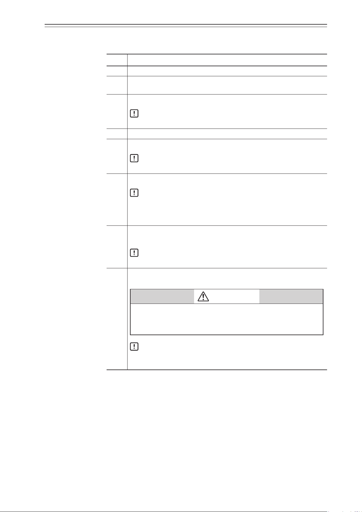
Safety precautions
Symbols
The purpose of the safety precautions listed here is to ensure the user uses the product
safely and correctly, to prevent harm to the user and other people and damage to property.
Make sure to observe the safety precautions.
Many different symbols are used in this manual.
Their appearance and meaning are described below. Thoroughly understand the
explanation before starting to read the main text.
WARNING
CAUTION
Sample symbols
This symbol indicates warnings and cautions for handling the device.
This symbol indicates prohibited actions that must not be taken.
This symbol indicates instructions for an action that must be taken.
Handling Precautions:
This symbol indicates a point to be noted when handling the device.
Wrong handling may cause the death or severe injury of the user.
Wrong handling may cause a minor injury to the user or damage to equipment.
ii
Page 5
Precautions for safe work
Do not perform wiring with wet hands or while the device is energized. This may lead to electric
shock. Turn the power off before starting the work and work with dry hands or use gloves.
Follow the work procedure defined in the explosion protection guidelines when performing the
power distribution work in an explosion-proof area.
For devices equipped with the pressure-resistant, explosion-proof specifications, do not open the
cover during operation (while the power is on).
Do not get on the installed device or use it as a step stool. This is dangerous because the device may
tip over.
Do not touch the device during operation without reason. This is dangerous because the surface may
be hot or cold depending on the usage environment.
Be careful not to touch the edge of the cover or the screw threads of the main unit when opening the
cover of the terminal box. You may be injured by these parts.
WARNING
CAUTION
Use a DC power supply with overload protection. Overload may cause smoke or fire.
If a tool or other item touches the glass part of the display, it may break, leading to an injury. Be
careful. Wear safety glasses during work.
This product is heavy. Be careful where you step and wear safety shoes during work.
Do not touch the feedback lever or other moving part while the device is operating. You may be
injured by getting your hand or other body part caught in them.
Properly use the power supply based on the specifications. Inputting a different power supply may
damage the device.
Use gloves and other protective equipment during work in a hot, cold, or other severe environment.
Do not move the device close to a magnet or magnetic driver. The control valve may operate.
Apply the correct supply air pressure in accordance with the specification of the device. The
overpressure may cause abnormal actions of the control valve or damage to the pressure gauge.
iii
Page 6
Unpacking, Verification, and Storage of Product
Unpacking
This device is precision measuring equipment. Carefully handle it to prevent accidents or
damage.
After unpacking, check that the items below are included.
• The device
• Feedback lever and hexagon socket bolts×2
• (4-mm) hexagon wrench×1 (for feedback lever) (Included only when the device is
shipped alone.)
• Solenoid valve (KZ03) (optional)
• Mounting plate set (optional)
• Pressure-resistant packing cable adapter and pressure-resistant elbow (option for
explosion-proof specifications)
• Instruction manual (this document) (Included if specified at the time of purchase.)
• Extension lever and hexagon socket bolts×2 (optional)
Specifications check
The specifications are shown on the nameplate of the main unit. Check that the specifications
are the same as what you specified. In particular, confirm the following points.
When using the device in an explosion-proof area, be sure to select the model that satisfies the
necessary explosion-proof requirements. Non-explosion-proof products cannot be used in an
explosion-proof area.
Contact
Storage
• Tag No. (TAG No.)
• Model (MODEL)
• Work No. (PROD.)
• Supply air pressure (SUPPLY)
• Explosion protection certification seal (for explosion-proof specifications)
WARNING
For inquiries about this device, please contact us.
When contacting us, let us know the model number and production number.
When storing the device after purchase, obey the following precautions.
• When storing the device before it has been used
1. Store the device as packed at shipment.
2. Store the device at an indoor location with little vibration or shocks and at normal
temperature and humidity (about 25°C, 65%).
• When storing the device after it has been used
1. Tightly secure the terminal box cover and block the conduit connection port with
tape to prevent humidity intrusion.
2. Block the three pneumatic piping connection ports (SUP, OUT1 and OUT2) with
tape to prevent humidity and dust intrusion.
3. Pack the device in the same way as at shipment.
4.
Store the device at an indoor location with little vibration or shocks where it will not be
exposed to rain or water and at normal temperature and humidity (about 25°C, 65%).
iv
Page 7

Table of Contents
Chapter 1. Structure of the 700 Series Control System 1-1
1-1. System Configuration
1-2. Structure of the Device and Description of Each Part 1-3
1-2-1. Structure of the Device 1-3
1-2-2. Structure of Terminal Box 1-5
1-2-3. Display on the Local User Interface (LUI) 1-7
1-1
Chapter 2. Installation of the 700 Series 2-1
2-1. Usage Conditions
2-2. Selection Criteria for Installation Location 2-3
2-2-1. Selection Criteria for Installation Location 2-3
2-3. Installation Procedure 2-5
2-3-1. Mounting the 700 Series onto the Actuator 2-5
2-3-2. Pneumatic Piping Connection 2-11
2-3-3. Electrical Wiring Connection 2-14
2-3-4. Cables 2-16
2-4. Cable gland and flameproof universal elbow for TIIS Flameproof apparatus 2-18
2-2
Chapter 3. Operation of the 700 Series 3-1
3-1. Local User Interface (LUI)
3-1-1. Displays 3-4
3-1-2. Disp_TB Display 3-5
3-2. Adjustment before Operation 3-14
3-2-1. Auto Setup 3-14
3-2-2. Zero Span Adjustment 3-17
3-2-3. Supply Bypass 3-20
3-2-4. Control Parameters 3-21
3-3. Starting Operation 3-23
3-3-1. Checking Fieldbus Operation 3-23
3-3-2. Preoperation Check 3-24
3-2
Chapter 4. Operations Using Fieldbus Communication 4-1
4-1. Fieldbus Communication Menus
4-2. Setup and Adjustment of Device 4-1
4-2-1. Process Variables 4-2
4-2-2. Auto Setup 4-2
4-2-3. Valve System 4-4
4-2-4. Control Configuration 4-5
4-2-5. Characterization 4-6
4-2-6. Final Value Cutoff 4-7
4-2-7. Units 4-7
4-2-8. Travel Calibration 4-8
4-2-9. Pressure Sensor Adjustment 4-9
4-2-10. Simulation 4-9
4-2-11. Test 4-10
4-2-12. Restore factory settings 4-11
4-2-13. Operator Action Records 4-11
4-2-14. Device Information 4-12
4-2-15. FF Option 4-12
4-3. Diagnostic Messages 4-13
4-3-1. Self-Diagnostic Messages 4-13
v
4-1
Page 8

4-3-2. Control Valve Diagnostic Messages
4-15
Chapter 5. Troubleshooting 5-1
5-1. Troubleshooting
5-1-1. The Device Does Not Operate. (There Is No Output Air Pressure.) 5-2
5-1-2. The Control Valve Operates Abnormally (There Is Output Air Pressure.) 5-3
5-1-3. Display Transducer Block Does Not Switch To Auto (LUI display says “DISP_OOS.”)
5-3
5-1-4. Adjustment Procedure When Hunting Occurs 5-4
5-1-5. Auto Setup Failure 5-5
5-2. Description of Messages 5-6
5-2
Chapter 6. Maintenance 6-1
6-1. A/M Switch
6-2. Replacement of Filter and Maintenance of Flow Restrictor 6-3
6-3. Cleaning the Flapper 6-4
6-4. Adjusting the Pilot Relay 6-5
6-5. Insulation Resistance Test 6-6
6-6. Adjustment Procedure When Using the Device with the Booster Relay Attached 6-7
6-7. Internal Block Diagram of the 700 Series 6-8
6-8. Resale Parts 6-8
6-8-1. Procedure to Change Switch Block 6-12
6-8-2. Procedure to Change Pilot Relay 6-13
6-2
Chapter 7. Notes on the Explosion-Proof 700 Series 7-1
7-1. TIIS Flameproof Model
7-2. ATEX Flameproof and Dust Ignition Protection 7-3
7-3. IECEx Flameproof and Dust Ignition Protection 7-5
7-4. FM Explosionproof/Dust Ignition Protection 7-7
7-5. FM Intrinsically safe (ic) and Nonincendive 7-8
7-6. FMC Explosionproof/Dust Ignition Protection 7-11
7-7. NEPSI Flameproof/Dust Ignition Protection 7-12
7-8. KOSHA Flameproof 7-14
7-9. INMETRO Flameproof/Dust Ignition Protection 7-15
7-10. EAC Flameproof 7-17
7-11. ATEX Intrinsic Safety and Dust Ignition Protection 7-18
7-12. IECEx Intrinsic Safety and Dust Ignition Protection (FISCO) 7-19
7-2
Appendix A. LUI Display Example A-1
Appendix B. Menu List B-1
Appendix C. Parameter List C-1
Appendix D. Specifications D-1
Appendix E. Model Configuration Table E-1
Appendix F. Outline Dimensional Drawing F-1
Terms and Conditions S2
vi
Page 9
Chapter 1 Structure of the 700 Series Control System
Air to the actuator
Control valve
Process fluid
Chapter 1. Structure of the 700 Series Control System
This chapter describes the device configuration of the control system that uses the device.
•
Description of the configuration of the input/output system in the device
•
Description of the structure of the main unit of the device and the name and function of
each part
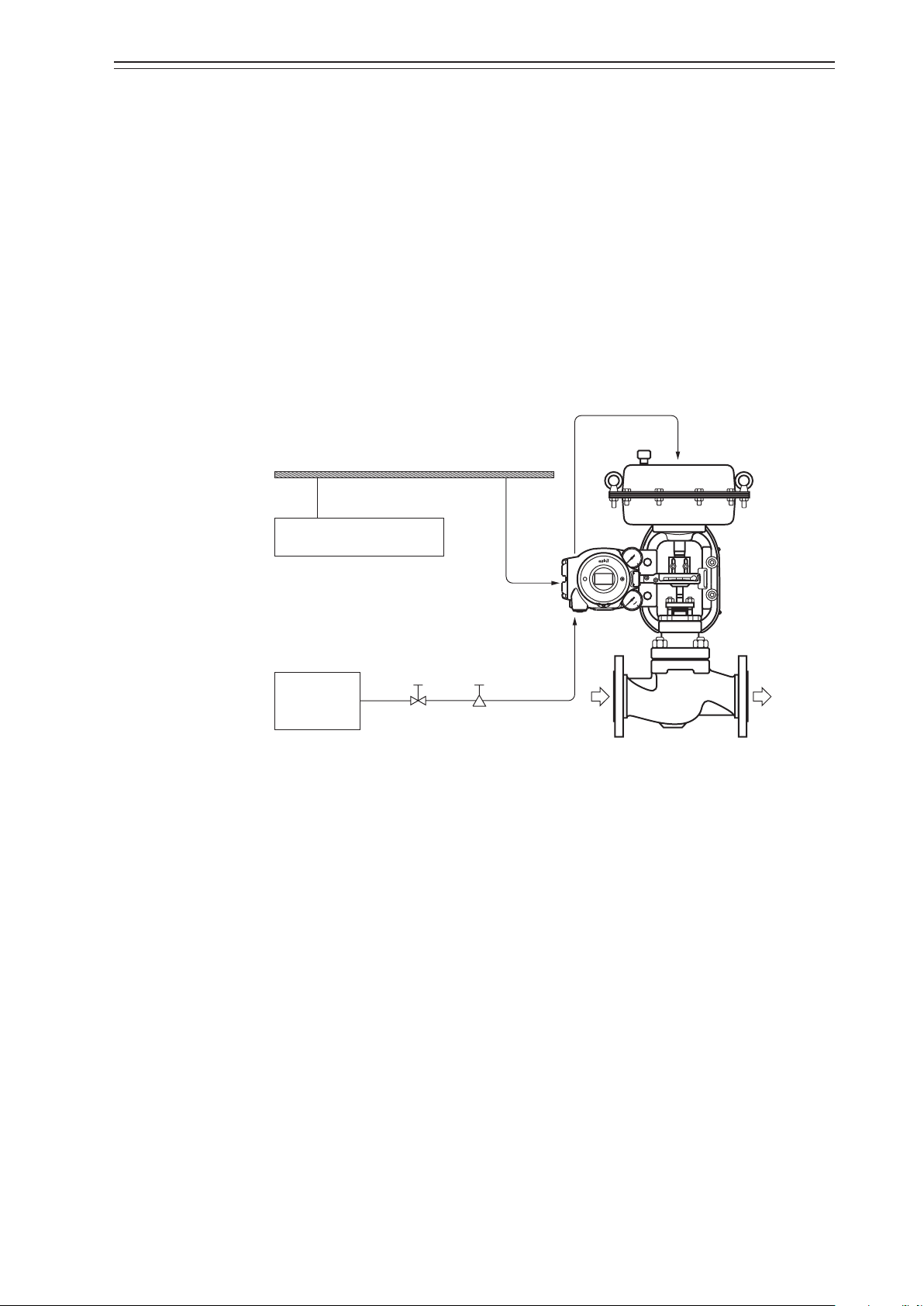
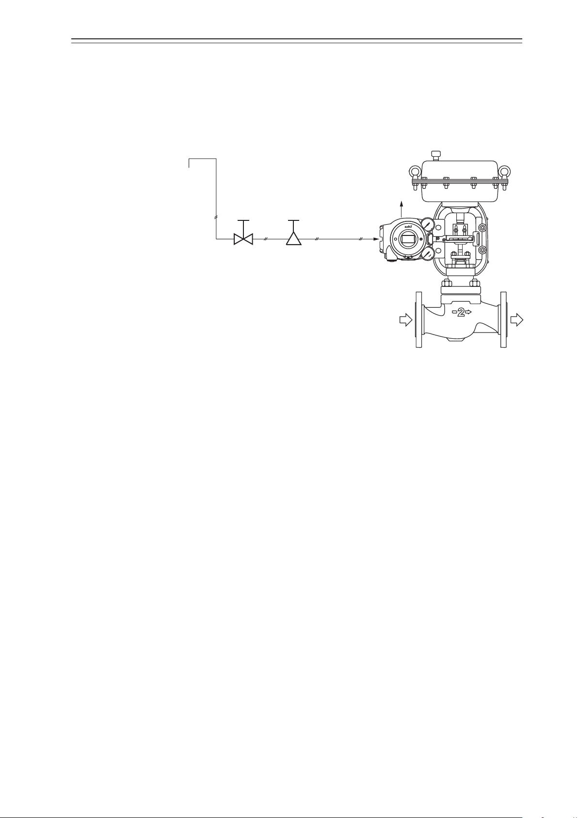
1-1. System Configuration
This device is a Fieldbus-enabled smart valve positioner and registered Foundation Fieldbus product.
The concept and the operation block diagram of the control valve control system that uses
the device are shown below.
Fieldbus
Other Fieldbus device
Air supply
system
Figure 1-1. Concept Diagram of the 700 Series Control System
Shutoff
valve
Device
Supply air
Solenoid valve
with filter
1-1
Page 10

Chapter 1 Structure of the 700 Series Control System
Fieldbus
CV
1) Operation block diagram
The block configuration of a typical function block and positioner is shown in the figure
below.
Resource
Block
PV
SP
PID
IN OUT
AO
Function
Block
Figure 1-2. Operation Block Diagram (AVP703)
Positioner
Transducer
Block
Position
sensor
−
Positioner
control section
Electropneumatic
transduction
section
Pilot
1-2
Page 11
Chapter 1 Structure of the 700 Series Control System
interface (LUI)
Output air pressure gauge
Output air connection port (OUT1)
Electrical conduit connection port
Terminal box cover
Output air connection port (OUT2)
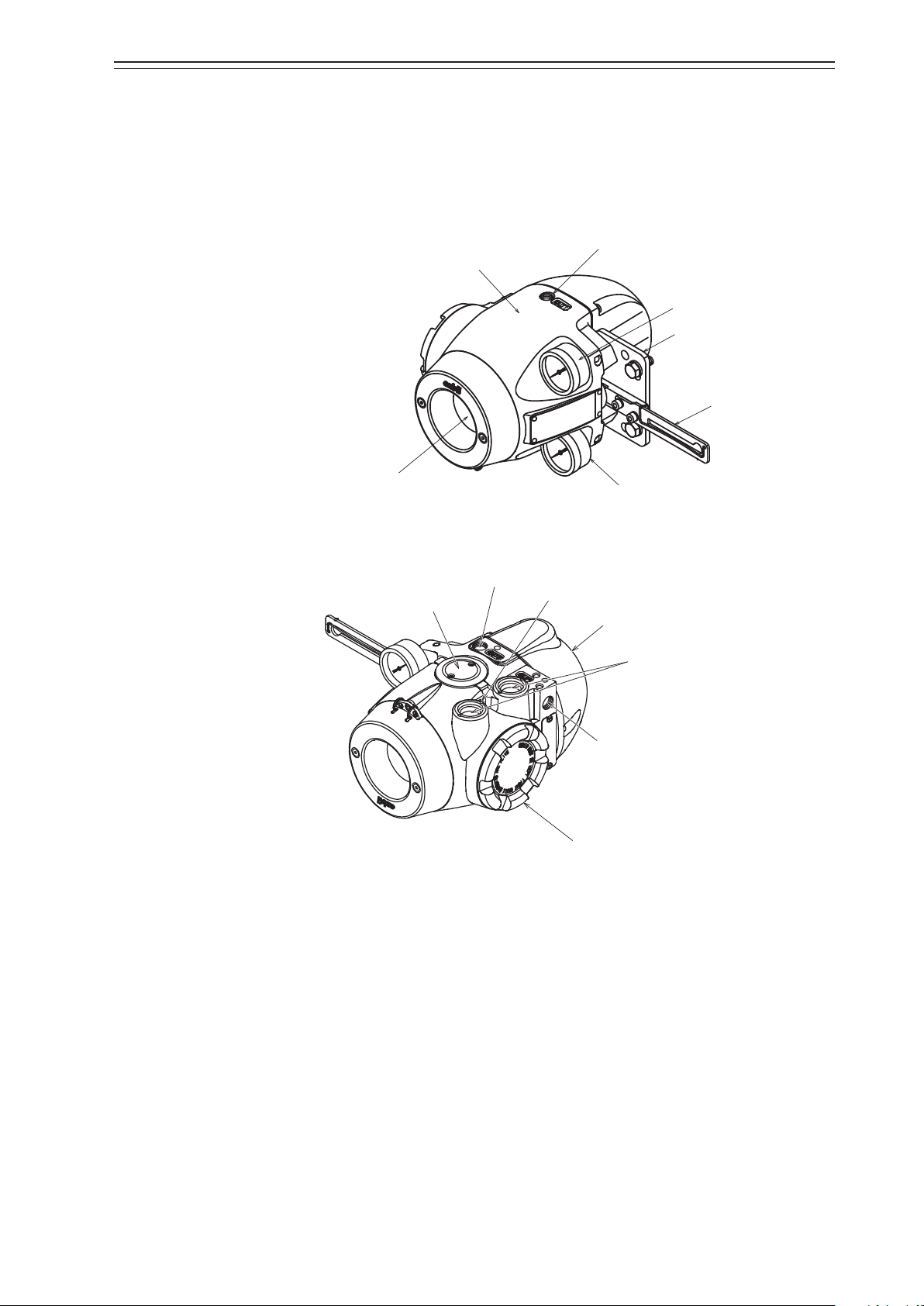
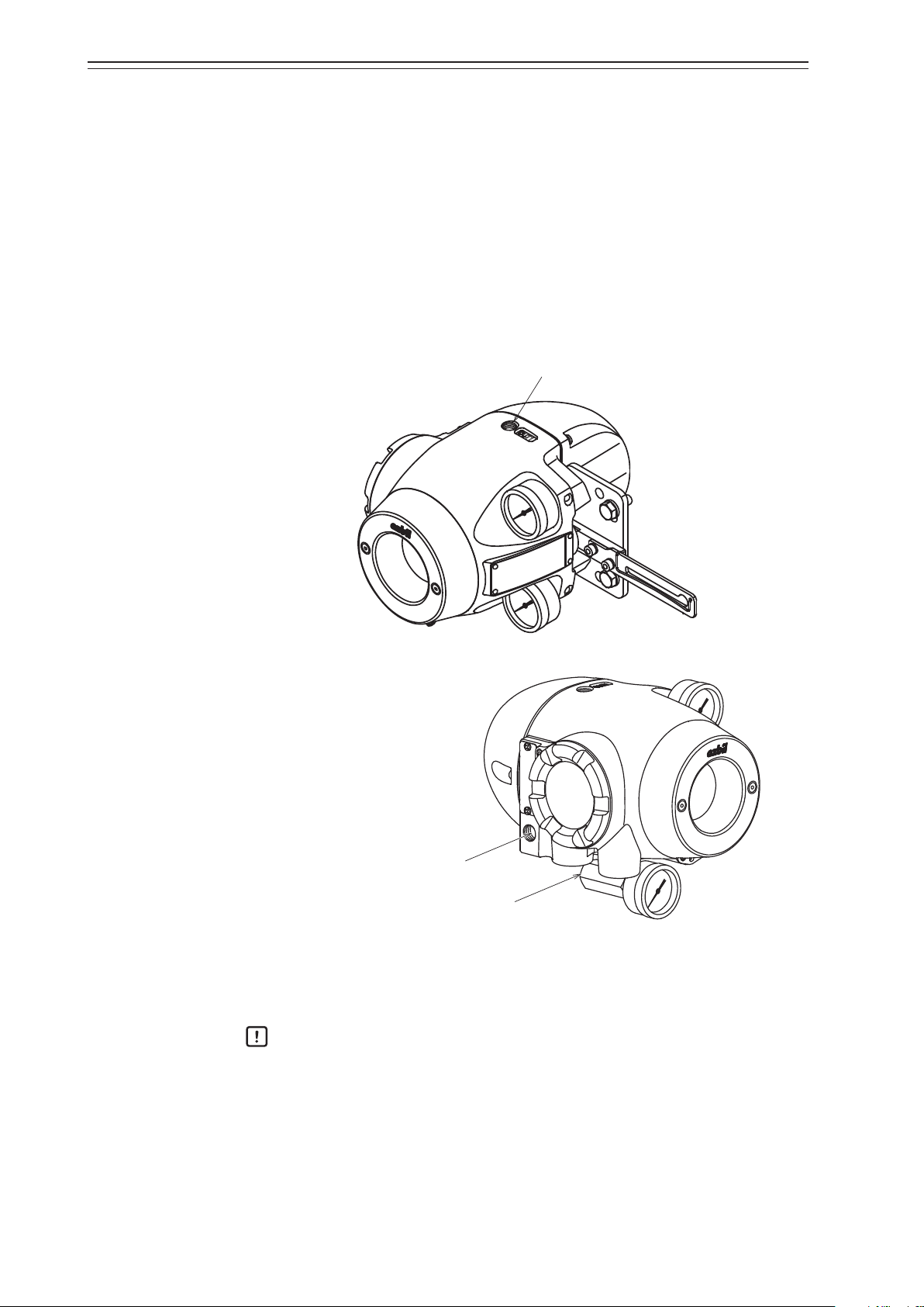
1-2. Structure of the Device and Description of Each Part
1-2-1. Structure of the Device
1) Major components
The structure of the main unit of the device is shown in the figure below.
Main unit
Mounting plate (optional)
Feedback lever
Local user
Exhaust cap
Supply air pressure gauge
Figure 1-3. Structure of the Device (Upper)
External grounding terminal
Pilot relay cover
Supply air connection port (SUP)
Figure 1-4. Structure of the Device (Lower)
1-3
Page 12

Chapter 1 Structure of the 700 Series Control System
2) Name and description of each part
The table below describes each part.
Name Description
Main unit
Pilot relay cover
Auto/Manual (A/M)
switch
Table 1-1. Description of Each Part
•
Houses electronic circuits, an electro-pneumatic transducer (EPM), a position sensor (VTD), and a pressure
sensor.
•
Cover of the pilot relay that amplifies the air signal from
the EPM (electro-pneumatic transducer) and transduces
it into the air signal sent to the actuator.
•
When you must adjust the balance pressure to switch
between the pilot relay for the single-acting actuator and
the pilot relay for the double-acting actuator, remove
this cover.
•
This switch is used to switch how the output air between
the auto operation status and the manual operation
status is controlled. This switch is built into the pilot
relay. This switch can be seen by removing the pilot relay
cover.
Feedback lever
Local user interface (LUI)
Supply air pressure gauge
Output air pressure gauge
Supply air connection
port (SUP)
Output air connection
port (OUT1)
Output air connection
port (OUT2)
Mounting plate (optional)
•
Extracts and transmits the movement of the control
valve lift to the VTD (position sensor).
•
The LUI allows you to adjust the zero span, perform
auto setup, and manually operate the device with the
LCD (liquid crystal display) and operation buttons without using the communicator.
•
Indicates the pressure of supply air.
•
Indicates the pressure of output air.
•
Supply air is input to this port.
•
“SUP” is displayed at this port.
•
Output air is sent out of this port to the actuator.
•
“OUT1” is displayed at this port.
•
Output air is sent out of this port to the actuator.
•
This port is blocked with a blind plug in the singleacting actuator.
•
OUT2 is displayed at the output port for the doubleacting actuator.
•
The mounting plate is used to mount the device onto the
actuator.
•
The shape of the mounting plate differs depending on
the specifications (actuator model).
1-4
Page 13
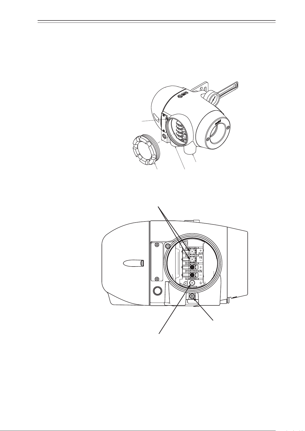
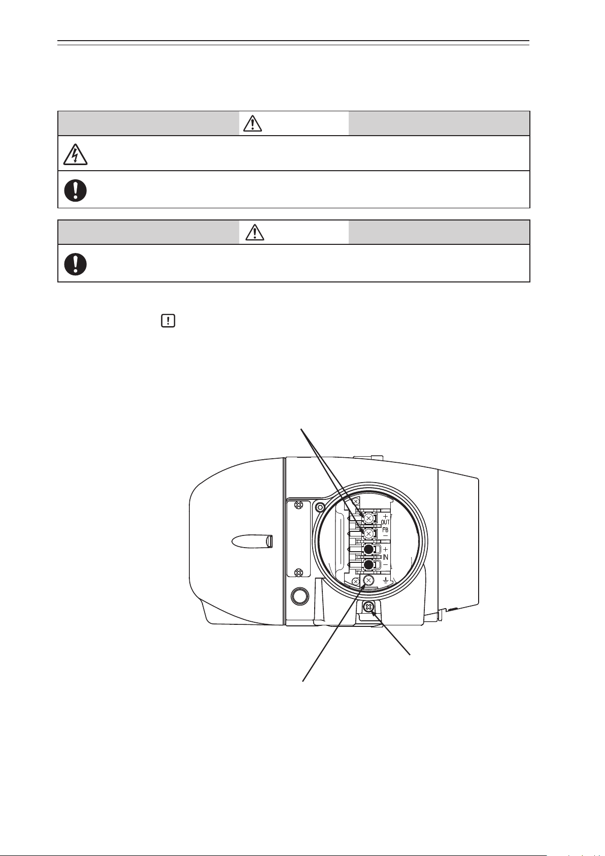
1-2-2. Structure of Terminal Box
Lock screw
Conduit connection port (2)
Conduit connection port (1)
box cover
1) Major components
The terminal box houses the Fieldbus terminal and the internal grounding terminal.
The structure of the terminal box is as shown below.
Chapter 1 Structure of the 700 Series Control System
Terminal
Figure 1-5. Structure of Terminal Box
M4 screw
for Fieldbus terminal
M4 screw
for external grounding terminal
M4 screw
for internal grounding terminal
Figure 1-6. Terminal Block in the Terminal Box
1-5
Page 14
Chapter 1 Structure of the 700 Series Control System
2) Name and description of each part
The table below describes each part of the terminal box.
Name Description
•
Terminal box cover
Lock screw
•
•
•
Fieldbus terminal
External grounding
terminal
Internal grounding
terminal
Conduit connection
port (1)
Conduit connection
port (2)
•
•
•
•
•
•
Table 1-2. Description of Each Part
Lid of terminal box.
This cover has a pressure-resistant explosion-proof structure.
Used to secure the terminal box cover.
“FB” is displayed at this terminal.
The Fieldbus signal cable is connected to this terminal.
External terminal for grounding. The cable for grounding is
connected to this terminal.
Internal terminal for grounding. The cable for grounding is
connected to this terminal.
Service entrance for a cable.
Service entrance for a cable.
This entrance is normally blocked with a blind plug.
WARNING
When using a pressure-resistant explosion-proof model in a dangerous place, be sure to use the
specified cable adapter for pressure-resistant packing for the conduit connection port. Securely
close the terminal box cover all the way. Then, rotate the lock screw counterclockwise to secure the
terminal box cover.
Handling Precautions:
Ground either the external or internal grounding terminal according to the
specifications. Be careful not to ground the device at two points.
1-6
Page 15
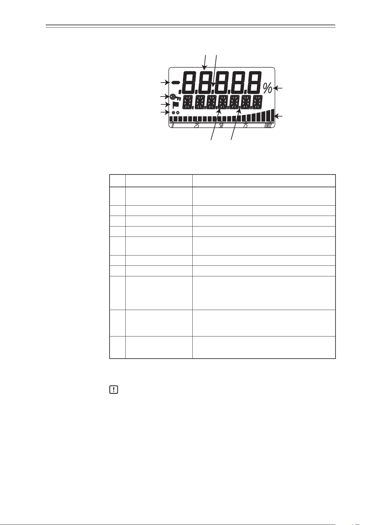
1-2-3. Display on the Local User Interface (LUI)
Chapter 1 Structure of the 700 Series Control System
(1)
(3)
(2)
(8)
(9)
(10)
(4)
(5)
(6)
(7)
Figure 1-7. Segments on the LUI
Table 1-3. Description of Each Part
No. Displayed element Main display
(1) 7 segments (5 digits)
Displays the main numerical values such as the specified opening.
(2) Minus sign Displays the sign for the 7-segment number.
(3) Decimal point (5 places) Displays the decimal point for the 7-segment number.
(4) 16 segments (7 digits) Displays the unit, status, or other data.
(5) Dot (6 places)
Displays the 16-segment auxiliary display, separator, or
other data.
(6) Percentage Displays %.
(7) Bar graph (22 bars) Displays the bar graph in percentage at a set point, etc.
On: LUI operation is unavailable.
(8) Key mark
Off: LUI operation is available.
Blinking: LUI is in operation.
When the self-diagnostic alarm is activated, the key
(9) Flag mark
mark is displayed. For detailed information of the
alarms, please refer to the status monitor of page 3-4 .
Display during operation
(10) Display refresh mark
White and black circles alternately blink.
For a display example, refer to “Appendix A. LUI Display Example.”
Handling Precautions:
The LUI buttons may not respond well near an electromagnetic inductor (such as
a large transformer or high-frequency furnace).
Remove sand, dust, and other foreign objects from the rubber parts of the
operation buttons before operating the LUI. Operating the LUI with foreign
objects on it may damage the rubber parts.
Do not pull the rubber parts of the operation buttons. This may deteriorate the
sealability, possibly causing malfunction.
1-7
Page 16

Chapter 1 Structure of the 700 Series Control System
1-8
Page 17
Chapter 2 Installation of the 700 Series
Chapter 2. Installation of the 700 Series
This chapter describes the usage conditions, installation, piping, and wiring of the device.
Precautions for safe work
WARNING
Do not perform wiring with wet hands or while the device is energized. This may lead to electric
shock. Turn the power off before starting the work and work with dry hands or use gloves.
Follow the work procedure defined in the explosion protection guidelines when performing the
power distribution work in an explosion-proof area.
For devices equipped with the pressure-resistant, explosion-proof specifications, do not open the
cover during operation (while the power is on).
CAUTION
Do not get on the installed device or use it as a step stool. This is dangerous because the device may
tip over.
Do not touch the device during operation without reason. This is dangerous because the surface may
be hot or cold depending on the usage environment.
Be careful not to touch the edge of the cover or the screw threads of the main unit when opening the
cover of the terminal box. You may be injured by these parts.
Use a DC power supply with overload protection. Overload may cause smoke or fire.
If a tool or other item touches the glass part of the display, it may break, leading to an injury. Be
careful. Wear safety glasses during work.
This product is heavy. Be careful where you step and wear safety shoes during work.
Do not touch the feedback lever or other moving part while the device is operating. You may be
injured by getting your hand or other body part caught in them.
Properly use the power supply based on the specifications. Inputting a different power supply may
damage the device.
Use gloves and other protective equipment during work in a hot, cold, or other severe environment.
Do not move the device close to a magnet or magnetic driver. The control valve may operate.
Apply the correct supply air pressure in accordance with the specification of the device. The
overpressure may cause abnormal actions of the control valve or damage to the pressure gauge.
2-1
Page 18

Chapter 2 Installation of the 700 Series
2-1. Usage Conditions
The device must be installed in the location, which satisfies the following conditions.
Also, the divice must be used in accordance with its specification.
Table 2-1. Range of Usage Conditions
Units
Basic
operating
conditions
Normal
operating
conditions
Marginal
operating
conditions
Transportation
conditions
General model °C +23 ±2 −40 to +80 −40 to +80 −40 to +70
TIIS flameproof model °C +23 ±2 −20 to +55 −20 to +55 −40 to +70
ATEX/IECEx/FM/
Operating
FMC/NEPSI/KOSHA/
EAC/INMETRO
flameproof model
°C +23 ±2 −30 to +75 −30 to +75 −40 to +70
temperature
range
FM Intrinsically Safe (ic)
and Nonincendive
°C +23 ±2 −24 to +75 −24 to +75 −40 to +70
ATEX/IECEx intrinsically safe model
°C 23±2 −40 to +60 −40 to +60 −40 to +70
(FISCO)
LUI °C +23 ±2 0 to +50 −40 to +80 −40 to +70
Power supply voltage V 9 to 32 9 to 32 32 —
Vibration
Amplitude *
Acceleration *
Friction of applied valve % 3 to 20 3 to 20
Supply air pressure Ps
(140kPa≤Ps≤700kPa)
Installation orientation *
1
1 *2
mm
m/s
p-p
0 15/(5 to 8 Hz) 15/(5 to 10 Hz) 15/(5 to 10 Hz)
2
0 20/(8 to 400 Hz) 40/(10 to 400 Hz) 40/(10 to 400 Hz)
0 to 3
20 to 100
—
kPa Ps ±1% 140 to 700 0 to 710 —
3
° ±1*
4
±180 ±180 ±180
Humidity range %RH 50 ±10 5 to 100 5 to 100 5 to 100
Each operating condition is defined as follows.
•
Basic operating condition: Range in which the accuracy is guaranteed
•
Normal operating condition: Range in which the positioner normally operates
•
Marginal operating condition: Range in which performance is not guaranteed but the device can be used with-
out being permanently damaged
•
Transportation condition: Environment condition range in which the non-operating device is not permanently
damaged during transportation
*1. Vibration conditions when the positioner cover is positioned at the center front.
*2. The pressure gauge is not applied.
*3. The slope characteristics are not included.
*4. The status where the drive shaft of the direct-acting actuator is perpendicular to the ground and that is used as the reference.
2-2
Page 19

2-2. Selection Criteria for Installation Location
The device is designed to withstand severe conditions, but the installation location should
be selected according to the criteria described below to maximize performance.
2-2-1. Selection Criteria for Installation Location
Install the device in a location that satisfies all of the following conditions.
•
Operating temperature range that conforms to the explosion protection rules
•
Relative humidity: 5 to 100%RH
•
Ambient temperature change rate: ±20°C/hr or slower
•
Electromagnetic induction: 400 A/m or less (Avoid places near a large transducer, highfrequency furnace, or other such equipment.)
•
Do not use a transceiver near the device.
•
Vibration: 20 m/s2 (5 to 400 Hz) or less (The vibration conditions defined for the device
are the vibrations at the positioner part.)
Chapter 2 Installation of the 700 Series
2-2-1-1. Criteria for instrumentation air
The device employs a nozzle flapper structure in the electropneumatic transduction section. If instrumentation air is contaminated (includes oil, water, or other substance), the
positioner function of the device may not function properly or an irrecoverable failure may
occur. Therefore, the quality of instrumentation air supplied to the device is defined as follows.
•
Solid material: No particles with a diameter larger than 3 μm.
•
Oil: Less than 1 ppm.
•
Supply air humidity: The dew point temperature is at least 10°C lower than that of the
(This criterion is based on Japanese Industrial Standards JIS C 1805-1(2001).)
Select a compressor and main line or terminal-installation type compressed air purifier by
referring to the above specifications.
(1) Compressed air purifier for the main line
Select a compressed air purifier for the main line, such as a main line filter or microalescer, to satisfy the above specifications.
Domestic compressed air purifier manufacturers of Japan: SMC Corporation and CKD
Corporation
device.
(2) Compressed air purifier to be installed on the terminal
If an air purifier cannot be installed on the main line due to installation of a control
valve or for other reasons, use an compressed air purifier that can be installed on the
terminal in order to satisfy the above specifications.
2-3
Page 20

Chapter 2 Installation of the 700 Series
<Example devices>
Products from SMC Corporation
•
Mist Separator AM150 or AM250 Series (Filtering level: 0.3 μm, Secondary oil mist
concentration: 1.0 mg/m3)
CKD Corporation
•
Oil mist filter
•
M1000 or M3000 Series
•
Mantle S Type (Filtering level: 0.3 μm, Remaining oil: 1.0 mg/m3)
Handling Precautions:
Select a compressed air purifier with specifications suited to the usage conditions.
Even when you install the above oil removal equipment, it is necessary to properly
inspect and maintain the air circuit section for long-term stable operation. Install
the oil removal equipment before use and perform periodic inspection and
maintenance.
The warranty is void if the device fails because the quality of the above
instrumentation air was not sufficient.
2-4
Page 21
2-3. Installation Procedure
2-3-1. Mounting the 700 Series onto the Actuator
The device is a smart valve positioner for use with a control valve that uses a direct-acting
or rotary actuator. The main unit of the device weighs approximately 4.2 kg. The basic
mounting procedure is the same as that for conventional electropneumatic positioners.
CAUTION
Be careful not to get injured by sharp parts such as the edge of the main unit or actuator or screw
threads during mounting.
The type of mounting plate, mounting method, and mounting procedure differ depending on the
actuator model to be mounted in the device.
If the device is not properly mounted, not only will the device not be able to operate at its true
performance but it may be damaged or fail. Pay attention to the following points.
•
The mounting plate and its accessories differ depending on the specifications (actuator model).
Be sure to use the appropriate mounting plate and accessories for the actuator to be mounted.
•
When installing the control valve, ensure as much surrounding space as possible and put the
device in the correct orientation taking maintainability (such as piping, wiring, and adjustment)
into consideration.
•
Deliver the device to the installation location in the packaged state if possible.
•
Do not apply excessive force to the feedback lever during mounting.
•
Do not bend the feedback pin.
•
Do not block the exhaust port located underneath.
•
Install the device so that the electrical conduit connection port does not face upward.
•
Securely tighten bolts.
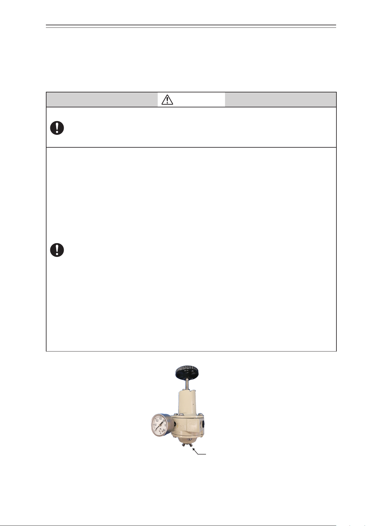
•
If the model KZ03 pressure regulator with filter is installed with the device, install with the drain
of the KZ03 facing downward. If the KZ03 cannot be attached vertically (with the drain facing
downward), install it separated from the AVP with the proper orientation.
•
In order to avoid the possibility of rainwater entering the pressure gauge, install the gauge
such that it does not face upward or downward. In addition, the pressure gauge has a rainwater
drain on its underside, so install the gauge with this hole facing downward.
•
If you install this device with the LCD facing upwards, use the LCD cover and pressure gauge
elbows as necessary, depending on the circumstances. For details, refer to 6) below, “Installing
the device with the LCD facing upwards.”
Chapter 2 Installation of the 700 Series
2-5
Drain plug
Page 22
Chapter 2 Installation of the 700 Series
Hexagon socket ange bolts (×2)
Yoke
AVP
Hexagonal bolt
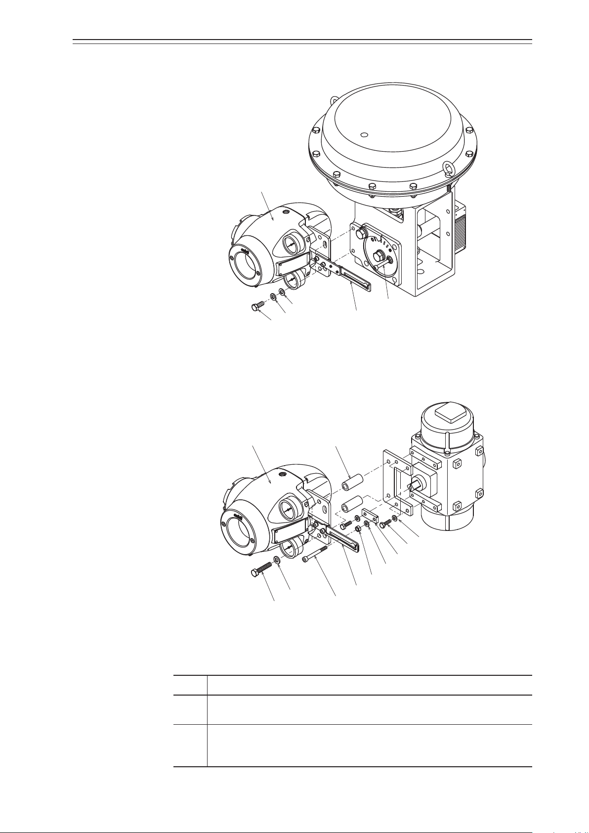
1) Mounting the feedback lever
Assemble the feedback lever from the front of the main unit of the device using the two
included hexagon socket bolts.
Assemble the extension lever as shown in the figure below if necessary.
Figure 2-1. Mounting Procedure for Feedback Lever
Figure 2-2. Mounting Procedure for Extension Lever
2) Mounting example
A typical mounting method is shown in the figure below. If your actuator is not shown in
the figure below, refer to the assembly diagram included with the device.
[Direct-Acting Actuator HA2 to 4, PSA1 to 4, 6, VA1 to 6 from Azbil Corporation]
Connector pin assembly
Plain washer
Spring washer
Feedback lever
Feedback pin
Figure 2-3. Mounting Procedure for Direct-Acting Actuator HA2 to 4, PSA1 to 4, 6, VA1 to 6 from Azbil Corporation
2-6
Page 23
[RSA1, 2, VR3 actuator from Azbil Corporation]
Hexagonal bolt
Hexagonal bolt
AVP
Chapter 2 Installation of the 700 Series
Plain washer
Spring washer
Feedback pin
Feedback lever
Figure 2-4. Mounting Procedure for RSA1, 2, VR3 Actuator from Azbil Corporation
[Example of double-acting rotary cylinder actuator]
SpacerAVP
Spring washer
Hexagonal bolt
Arm
Spring washer
Spring
washer
Feedback pin
Hexagonal nut
Feedback lever
Figure 2-5. Mounting Procedure for Double-Acting Rotary Cylinder Actuator
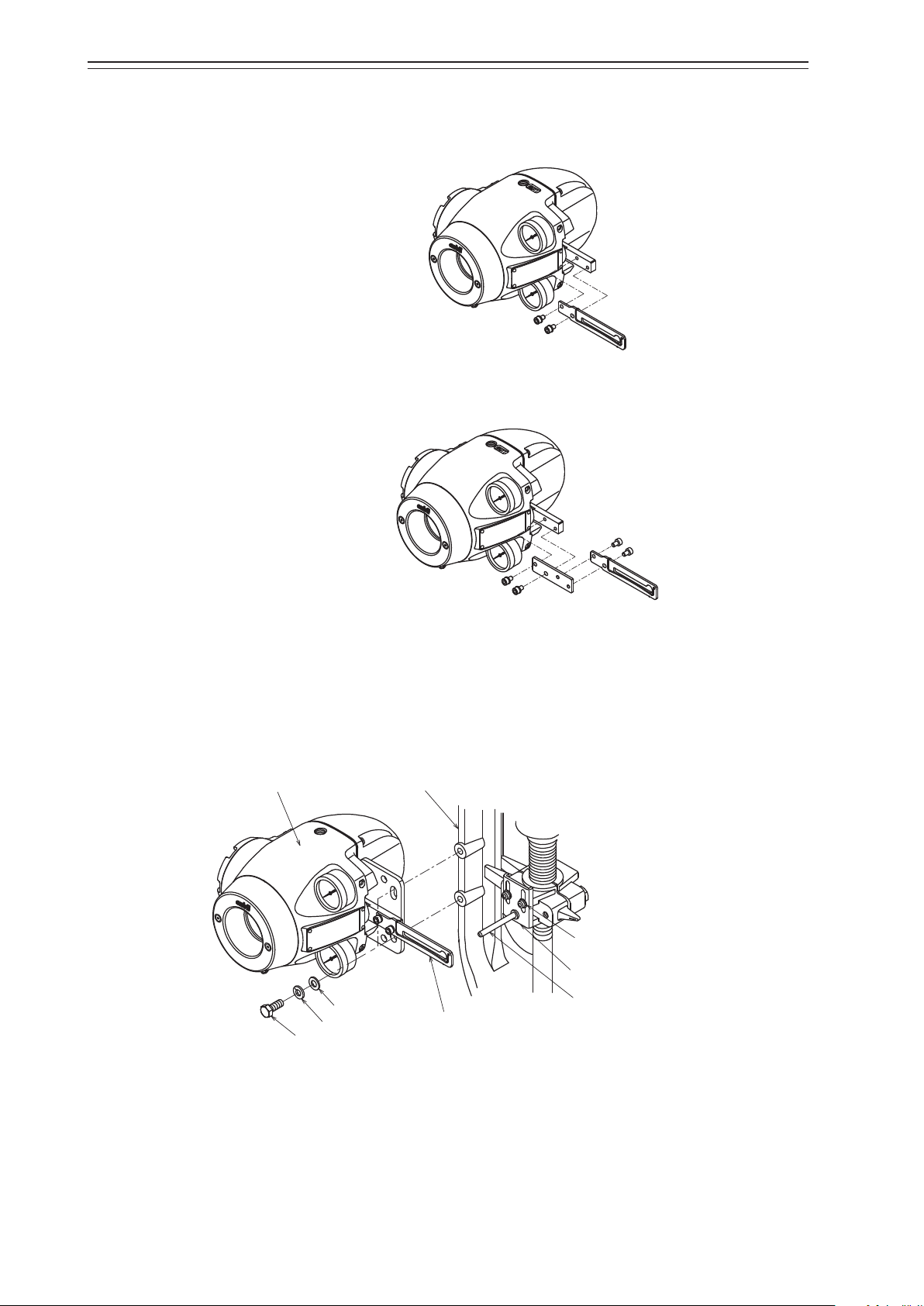
3) Mounting procedure
The procedure for mounting the feedback lever onto the actuator is shown below.
Step Description
Tightly secure the mounting plate by inserting hexagonal bolts (M8×20) with
1
spring washers into the (two) screw holes at the rear of the device.
Tightly secure the device (mounting plate) onto the mounting seat of the actua-
2
tor by using bolts and washers. At this time, insert the actuator feedback pin into
the slotted hole of the feedback lever in the device.
2-7
Page 24
Chapter 2 Installation of the 700 Series
Spring (cross section)
30°
30°
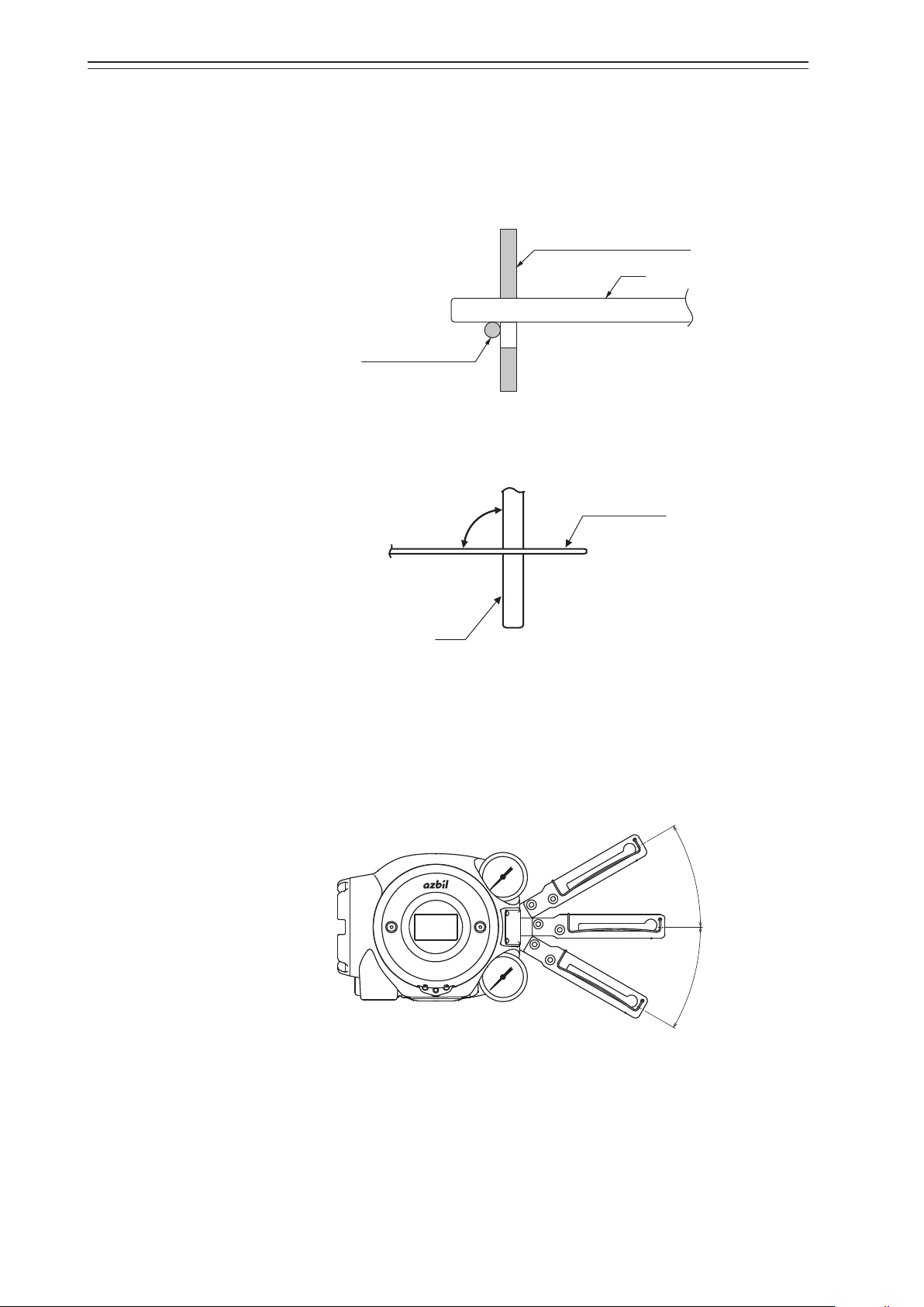
4) Connection of feedback pin and feedback lever (1)
There are several points to be careful of when connecting the feedback lever to the device
and the actuator feedback pin. Connect correctly.
•
Only a pin with a diameter of 6 mm can be used.
•
Insert the pin between the guide and the spring.
•
Make the feedback lever perpendicular to the pin when viewed from the above.
Feedback lever (cross section)
Pin
Figure 2-6. Connection of Feedback Lever and Feedback Pin
90°
Pin
Feedback lever
Figure 2-7. Angle between Feedback Lever and Pin
•
Mount the lever so that it is horizontal when opened by 50%.
•
The allowable rotation angle of the feedback lever is horizontal ± 30°. If the angle exceeds ±30°, the self-diagnostic function detects Valve Travel Detector Out of Range and
the device will not operate normally. (The accuracy is guaranteed when the rotation
angle is between ±4° and ±20°.)
Figure 2-8. Operation Angle of Feedback Lever
2-8
Page 25
Chapter 2 Installation of the 700 Series
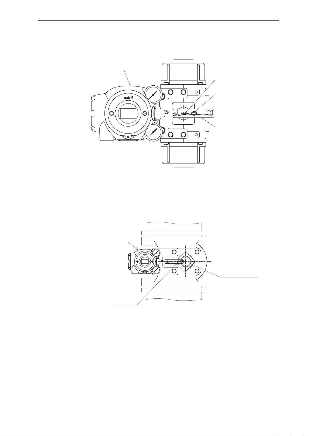
Shaft of rotary cylinder
Feedback pin
Shaft of rotary cylinder
•
When assembling the lever onto a rotary cylinder so that the shaft of the rotary cylinder
is positioned between the feedback pin and the 700 Series as shown in the figure below,
select Rotary/90° (for 90°) or Rotary/other (for angles other than 90°) as the Actuator
Type according to the rotation angle.
AVP
Feedback pin
Feedback lever
Figure 2-9. Connection of the Rotary Cylinder to the Feedback Pin and Feedback Lever
•
When the rotary cylinder is large and the lever is assembled so that the feedback pin is
positioned between the 700 Series and the shaft of the rotary cylinder as shown in the
figure below, select Rotary (sub)/90° (for 90°) or Rotary (sub)/other (for angles other
than 90°) as the Actuator Type according to the rotation angle.
AVP
Figure 2-10. Connection of the Rotary Cylinder to the Feedback Pin and Feedback
Lever(Large cylinder)
5) Maintenance space behind the device
The device has a nozzle flapper mechanism in the back of the main unit. When cleaning
the flapper, you must remove the pilot relay cover secured to the back with three screws.
Design the clamp and feedback mechanism to ensure maintenance space for cleaning.
2-9
Page 26
Chapter 2 Installation of the 700 Series
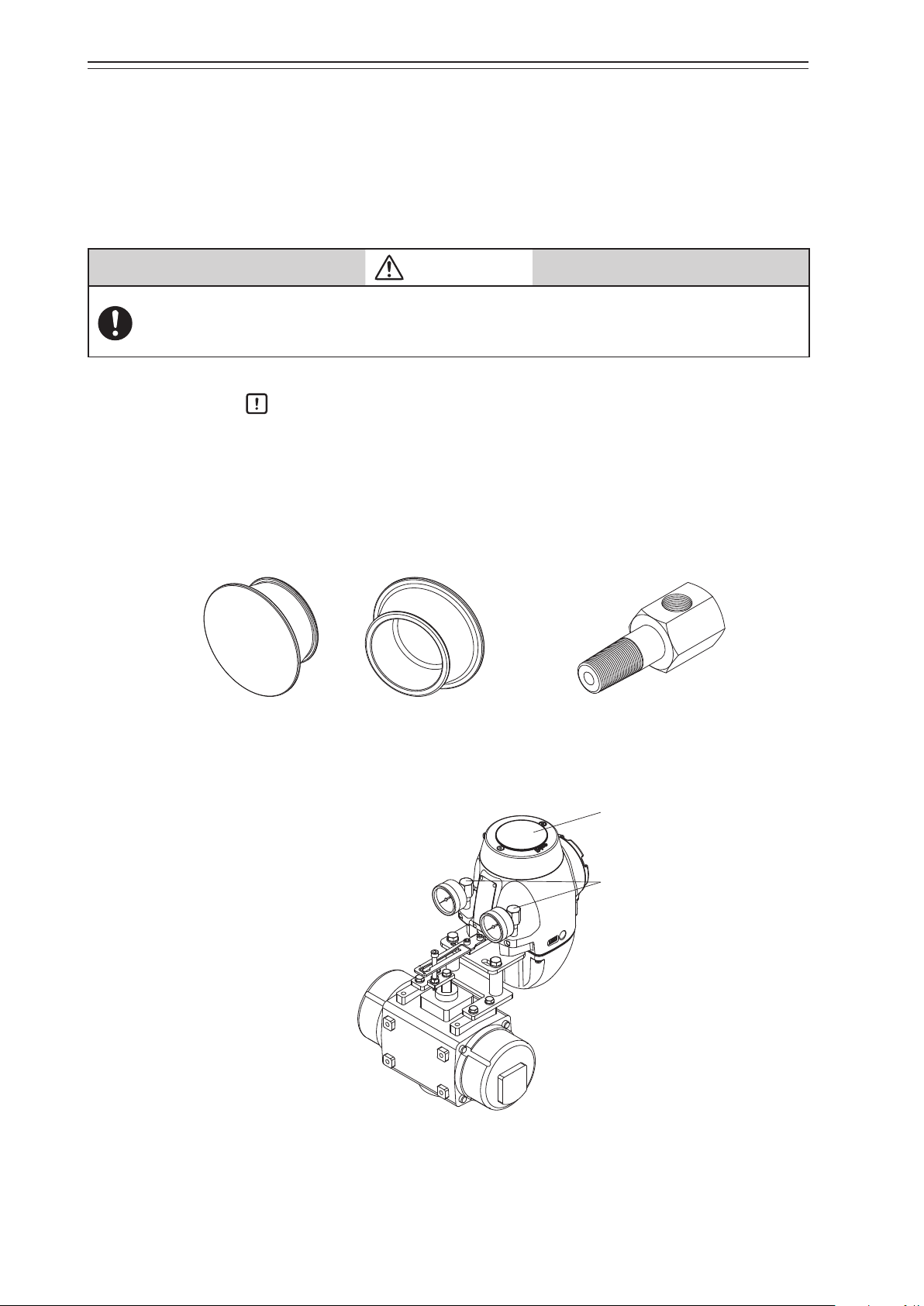
6) Installing the device with the LCD facing upwards
If you install the device with the LCD facing upwards, use the accessories below as required depending on the circumstances. (Refer to 6-9, “Resale Parts.”)
•
LCD cover (material: silicone rubber)
This cover reduces deterioration of the LCD due to sunlight (ultraviolet radiation). Use
the cover if the device is used in a place with strong sunlight (outdoors, etc.).
Before mounting or removing the LCD cover, it is necessary to remove the face cover from the main
unit. Take care as you work not to touch sharp parts of the face cover, such as the rim. You might be
injured.
Handling Precautions:
Remove the face cover when checking the LCD.
•
Pressure gauge elbows (Connection: Rc1/8)
The elbows are for mounting the pressure gauges if the device is installed in a place with
direct exposure to rainwater (outdoors, etc.). (If the pressure gauges are installed facing
upward, they will be damaged by rainwater.
CAUTION
Front Back
Figure 2-11. LCD cover Figure 2-12. Pressure gauge elbow
LCD cover
Pressure gauge elbow
Figure 2-13. Example of LCD cover and pressure gauge elbow mounting
2-10
Page 27
2-3-2. Pneumatic Piping Connection
Supply air
This section describes how to supply the air for the device to drive the actuator.
1) Air supply system
Supply air must be clean and dry to stably use the device for a long time. A typical example
of an air supply system is shown in the figure below.
Chapter 2 Installation of the 700 Series
Shuto
valve
Solenoid valve
with lter
Supply air piping
Figure 2-14. Air Supply System
Output air
piping
2) Supply air
Use supply air that conforms to the instrumentation air standards (on page 2-2).
3) Solenoid valve with filter
•
The solenoid valve with filter is used to adjust the pressure of the supply air to the device.
•
Install this valve as close to the main unit of the device as possible.
•
The control valve can be manually operated by using the A/M switching function. (The
double-acting actuator does not support manual operation.)
•
Use a 3-μm or finer filter.
•
The filter removes solid materials from supply air.
•
If the filter is not equipped, separately insert a (3-μm or finer) filter immediately before
the solenoid valve.
•
Install the solenoid valve so that the drain faces downward.
•
If you select the built-in Azbil solenoid valve KZ03, the filter is built into the device before shipment.
4) Shutoff valve
•
The shutoff valve is used to temporarily stop supplying air to the device.
•
With this valve, the device or control valve can be removed without having to stop the
whole air supply system during maintenance or other operations.
2-11
Page 28
Chapter 2 Installation of the 700 Series
Output air connection port (OUT1)
Rc1/4 or 1/4NPT
5) Piping
•
Use piping with an inside diameter of 6 mm.
•
When using the device in a corrosive atmosphere, select piping appropriate to the environment of the installation location. For example, you may use the vinyl-coated copper pipe.
•
To prevent air leaks, be sure to use a fitting that is appropriate for the pipe.
6) Connection positions
The positions of the supply air connection port and output air connection port are shown
in the figure below. Select the dimensions of the connection port screws according to the
specifications.
Rc1/4 or 1/4NPT
Handling Precautions:
Output air connection port (OUT2)
(For double-acting actuator)
Figure 2-15. Pneumatic Piping Connection
When connecting the electromagnetic valve for emergency shutoff, air valve, or
other part, install it between the output air connection and the actuator rather
than the supply air connection side of the device.
2-12
Page 29

Chapter 2 Installation of the 700 Series
7) Mounting procedure
The procedure for connecting pneumatic piping to operate the device is shown below.
Step Description
Connect the joint for piping to the connection port using seal tape.
Handling Precautions:
•
1
Use seal tape as the seal material. Avoid using solid or liquid seal material
if possible.
•
Do not let the seal tape get in the piping.
•
If you do use a liquid seal, make sure that no drops of the seal material get
in the piping.
Connect the supply and output pipes to each joint in consideration of the arrangement of the piping.
Handling Precautions:
•
2
3 After all piping is complete, make sure that air does not leak.
For the double-acting actuator, the connection between output air connection ports OUT1 and OUT2 and the actuator is determined by the
valve operation. Check the valve operation before connecting pipes.
•
Sufficiently flush piping before connection to prevent burrs on the piping
or other foreign objects from getting in the piping.
•
Keep the output air piping as short as possible.
2-13
Page 30
Chapter 2 Installation of the 700 Series
M4 screw
for external grounding terminal
2-3-3. Electrical Wiring Connection
This section describes how to connect electrical wiring for signal inputs from the controller.
Turn the power off before starting wiring work. Otherwise, electric shock may occur.
When using the explosion-proof 700 Series in a dangerous place, be sure to connect the wiring while
following “Chapter 7. Notes on the Explosion-Proof 700 Series.”
Be sure to perform grounding work following the electrical work guidelines in each region.
Handling Precautions:
Be sure to attach a blind plug to the unused conduit connection port so that it is
completely covered.
WARNING
CAUTION
1) Connection positions
The figure below shows the terminal block in the terminal box.
for Fieldbus terminal
M4 screw
M4 screw
for internal grounding terminal
Figure 2-16. Terminal Block in the Terminal Box
2-14
Page 31

Chapter 2 Installation of the 700 Series
2) Terminal for external grounding
Connect the external grounding terminal to the case with two washers as follows.
Cable lug
Washer
Washer
Figure 2-17. Connection of External Grounding Terminal
3) How to install a Fieldbus network
There are two ways to install a fieldbus network.
(1) Bus type: Connect each field device from the trunk cable within 1 m.
(2) Tree type: Install the trunk cable to the field and connect feeder cables from a junc-
tion box to each field device.
Bus type
Host
Terminator
Power
supply
Host
Power
supply
Trunk cable
Split terminator
(Branch wire: less than 1 m)
Tree type
Trunk cable
Spur
(feeder cable)
Junction box
(terminator built-in)
Figure 2-18. How to Install Fieldbus Networks
2-15
Page 32

Chapter 2 Installation of the 700 Series
4) Precautions for installing cables
Note the following points when installing a cable.
•
Route the cable so as to avoid high-capacity transducers, motors, power supplies for
engines, or other devices that generate noise. Do not put a cable in the same tray or
duct as a cable for an engine.
•
We recommend using conduits and ducts to route cables for waterproofing and protection from damage. Be sure to use a waterproof adapter at the conduit connection
port.
•
When routing cables in a place subject to electromagnetic noise, use conduits and
ducts.
2-3-4. Cables
1) Selection and conditions of cables
The criteria for selection and the conditions of cables for wiring are described below.
•
We recommend using 600-V plastic insulated sheath electric wire CVV (JIS C 3401 by
Japanese Industrial Standards) for control with a conductive cross-section of 1.25mm2
or a stranded cable with equivalent or higher performance.
•
When routing cable in a place subject to electromagnetic noise, use shielded wire CVVS
(JCS 4258 by the Japanese Electric Wire & Cable Makers’ Association) and metal conduits.
•
Select a sheath material that withstands the cable installation environment (including the
ambient temperature, corrosive gas, and corrosive liquid).
Use cable with an outside diameter of 7 to 12mm. When using a pressure-resistant packing cable adapter, be sure to use packing appropriate for the outside diameter of the cable.
A crimping terminal with insulated sleeve (for M4 screw) is recommended for terminals.
2) Types of Fieldbus cables
The maximum length of Fieldbus cable depends on the cable type. Refer to the table below.
Type Description of cable Size (mm2)
Type A Twisted pair wire with individual shields 0.8 (18AWG) 1900
Type B Common shielded multiple twisted pair wire 0.32 (22AWG) 1200
Type C Unshielded multiple twisted pair wire 0.13 (26AWG) 400
Type D Single unshielded wire 1.25 (16AWG) 200
Maximum
length (m)
Handling Precautions:
Model AVP703 is intended for use in industrial locations defined in CE marking
directive (EN 61326-1).
2-16
Page 33
Chapter 2 Installation of the 700 Series
3) Wiring procedure
The procedure for electrical wiring to operate the device is shown below.
Step Description
1 Turn off the Fieldbus power supply.
Rotate the lock screw (M4) on the terminal box cover with a (3-mm) hexagonal
2
wrench clockwise to loosen it.
Rotate the terminal box cover counterclockwise to remove it.
3
4 Remove the dust-proof plug from the conduit connection port.
5
Handling Precautions:
•
Be careful not to damage the paintwork with a tool or other object.
Insert the cable into the conduit connection port.
Handling Precautions:
•
Be careful not to damage the sheath of the cable.
Wire the cable to the relevant terminal in the terminal box.
Handling Precautions:
6
7
•
Be careful of the polarity.
•
Sufficiently tighten the terminal screw. The recommend tightening torque
is 1.5N·m.
Apply sufficient waterproof treatment to the conduit to prevent rainwater or
other liquid from entering inside.
Handling Precautions:
•
We recommend using silicon non-hardening seal material.
Mount the terminal box cover, sufficiently tighten it with an appropriate tool,
and then secure the cover by rotating the lock screw counterclockwise.
CAUTION
•
Be careful not to get your finger caught in the clamp.
8
•
Be careful not to hurt your finger with the edge of cover or the screw
threads of the main unit.
Handling Precautions:
•
Be careful not to damage the paintwork of the device with a tool or other
object.
2-17
Page 34

Chapter 2 Installation of the 700 Series
O-ring
Cable diameter
2-4. Cable gland and flameproof universal elbow for TIIS Flameproof
apparatus
TIIS Flameproof SVP model is provided with a certified cable gland.
The cable gland seals the cable entering the SVP enclosure to withstand an internal explosion and protects the cable from being damaged mechanically and electrically.
Use the dedicated elbow if it is necessary to change the direction of the cable with these
models.
Handling Precautions:
If the device is to be used under the authorization other than that for the TIIS
Flameproof standards, the wiring of cables must be performed according to local
regulations for electrical installations in explosive atmospheres.
1) Structure of the flameproof cable gland
The Flameproof cable gland is shown below in assembled and exploded views.
Cable diameter ≤ 8mm
Clamp
(Upper)
≥ 8mm
Clamp
(Lower)
Figure 2-19. Flameproof cable gland
Hexa-recess stopper screw
Body
O-ring
Gland
Coupling
O-ring
Clamp
(Upper)
Cross recessed
head screws
Washer
Sealing ring
Washer
Hexa-recess stopper screw (Two)
Union nut
Cross recessed
head screws
Hexa-recess stopper screw (Two)
Gland
Coupling
O-ring
Union nut
Figure 2-20. Constituent elements of flameproof cable gland
2-18
Page 35

Chapter 2 Installation of the 700 Series
Lock nut
2) Structure of the flameproof universal elbow
The figure below shows the universal elbow.
O-ring
Elbow
Figure 2-21. Flameproof elbow
3) Mounting example
The flameproof cable gland and the universal elbow are used to connect the field wiring
cable to the device enclosure, as shown below.
a) Use of flameproof cable gland
b) Use of flameproof cable gland and elbow
Figure 2-22. Mounting example of flameproof cable gland and elbow
2-19
Page 36

Chapter 2 Installation of the 700 Series
4) Mounting procedure for flameproof cable gland
The procedure for mounting the flameproof cable gland is shown below.
Step Description
Securely screw the main unit of the adapter into the conduit connection port of
the terminal box or into the flameproof universal elbow, and fasten the hexagon
socket bolt.
1
Refer to the illustrations and insert the cable carefully.
2
Handling Precautions:
•
Apply adequate waterproofing to these parts. We recommend the use of
silicone resin based non-hardening seal materials.
WARNING
If the diameters of the cable and the packing do not match each
other, the propagation of flame cannot be prevented. Refer to the
table below and select a packing adaptor whose internal diameter matches the outer diameter of the cable.
Cable outer diameter (mm) Packing inner diameter (mm) Notes
7.0 to 8.0 8 Provided
8.0 to 10.0 10 Built in
10.0 to 12.0 12 Provided
The cable outer diameter is 8mm max., fix the cable gland with
the clamps.
Handling Precautions:
•
Pay attention to the surface of the device. Tools may cause damage the
surface.
Screw the gland into the main unit of the adapter to secure it in place.
WARNING
3
4 Pass the cable through the body and insert it into the terminal box.
Screw the union nut onto the body and tighten it down securely to hold it in
5
place. Then, tighten the union nut's recess screw.
To prevent injuries due to a spark travel, be sure to tighten down
the packing adequately.
2-20
Page 37

Chapter 2 Installation of the 700 Series
Elbow
Lock nut
O-ring
O-ring groove end surface
5) Mounting procedure for flameproof universal elbow
The procedure for mounting the flameproof universal elbow is shown below.
Step Description
Align the end surface of the lock nut with the end surface of the O-ring groove
as shown below.
Lock nut end face
1
Figure 2-23. Arrangement of lock nut and O-ring
Screw the flameproof universal elbow into the terminal box conduit connection
port until the lock nut end surface hits the connection port end surface.
When two elbow are used, at first, screw the first elbow into the terminal box.
Next, screw the second elbow into the terminal box in the reverse direction to
2
the first elbow.
Handling Precautions:
•
Apply adequate waterproofing to these parts.
Turn the flameproof universal elbow to loose in the desired direction.
3
4
Handling Precautions:
•
Do not loosen it more than 1 turn.
Lock the flameproof universal elbow in place by tightening down the lock nut
using the special tool.
2-21
Page 38

Chapter 2 Installation of the 700 Series
2-22
Page 39

Chapter 3 Operation of the 700 Series
Chapter 3. Operation of the 700 Series
This chapter describes how to start operating the device and adjust the device using the
local user interface (LUI). When you purchase the device alone, be sure to read “Installation of the 700 Series” before reading this chapter.
Precautions for safe work
WARNING
Do not perform wiring with wet hands or while the device is energized. This may lead to electric
shock. Turn the power off before starting the work and work with dry hands or use gloves.
Follow the work procedure defined in the explosion protection guidelines when performing the
power distribution work in an explosion-proof area.
For devices equipped with the pressure-resistant, explosion-proof specifications, do not open the
cover during operation (while the power is on).
CAUTION
Do not get on the installed device or use it as a step stool. This is dangerous because the device may
tip over.
Do not touch the device during operation without reason. This is dangerous because the surface may
be hot or cold depending on the usage environment.
Be careful not to touch the edge of the cover or the screw threads of the main unit when opening the
cover of the terminal box. You may be injured by these parts.
Use a DC power supply with overload protection. Overload may cause smoke or fire.
If a tool or other item touches the glass part of the display, it may break, leading to an injury. Be careful. Wear safety glasses during work.
This product is heavy. Be careful where you step and wear safety shoes during work.
Do not touch the feedback lever or other moving part while the device is operating. You may be injured by getting your hand or other body part caught in them.
Properly use the power supply based on the specifications. Inputting a different power supply may
damage the device.
Use gloves and other protective equipment during work in a hot, cold, or other severe environment.
Do not move the device close to a magnet or magnetic driver. The control valve may operate.
Apply the correct supply air pressure in accordance with the specification of the device. The overpressure may cause abnormal actions of the control valve or damage to the pressure gauge.
3-1
Page 40
Chapter 3 Operation of the 700 Series
socket bolts
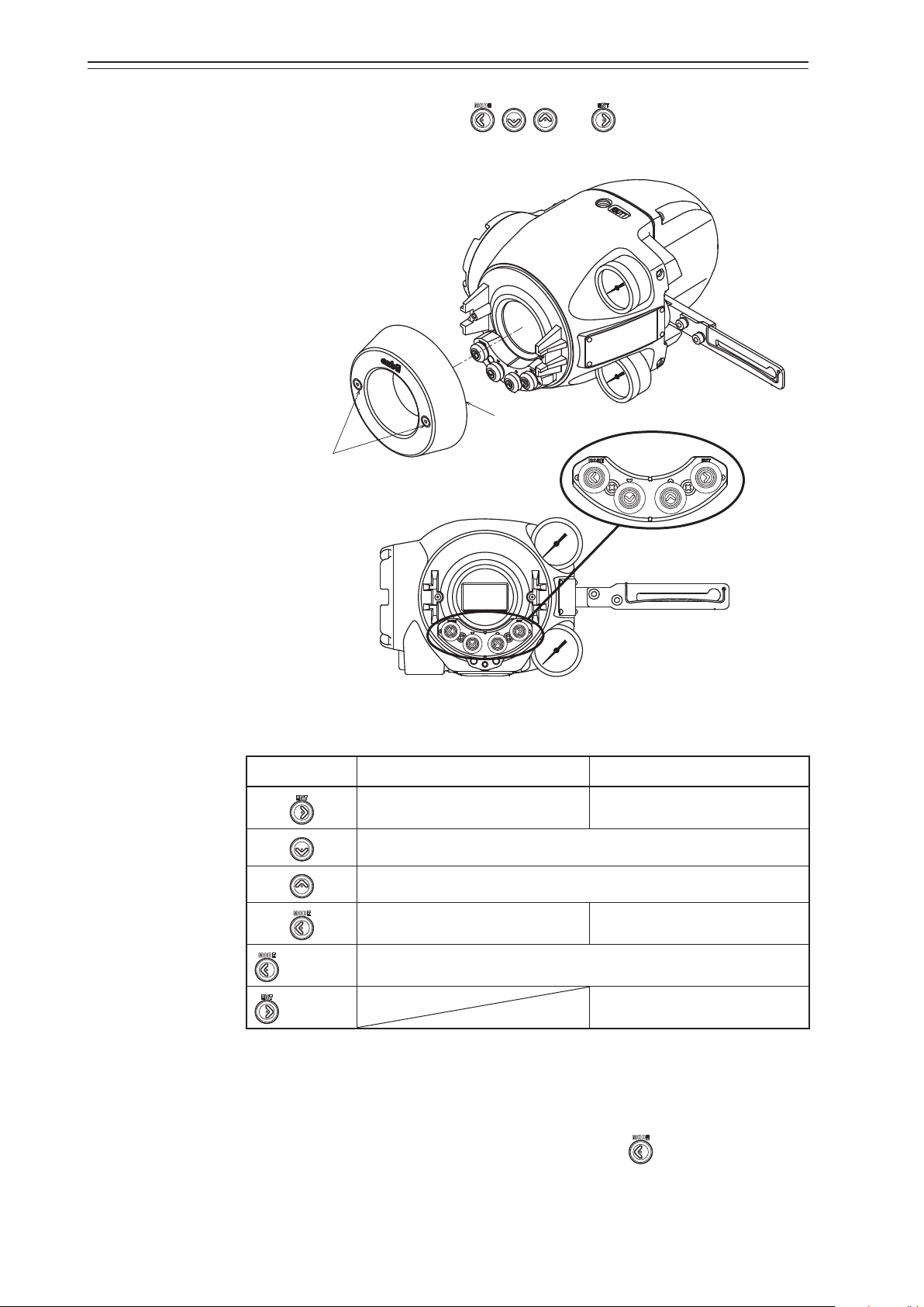
3-1. Local User Interface (LUI)
Four push buttons on the LUI (with , , , and symbols) can be operated by
removing two screws ((2.5-mm) hexagonal socket bolts) from the front cover of the device.
Front cover
Hexagonal
Operation
buttons
Figure 3-1. LUI Structure with the Front Cover Removed
Table 3-1.
Key input Monitor mode Setup mode
Switches between display categories. Goes to the next display.
Selects the next item.
Selects the previous item.
Switches between display categories. Goes back to the previous display.
Hold down
Hold down
Switches between setup mode and monitor mode.
Executes the function.
The LUI supports the monitor and setup modes.
In monitor mode, the normal, detailed, status, and FF monitors are available. The normal
monitor can be used to monitor data such as opening and input signals and it displays
alarm information if a self-diagnostic alarm is issued.
To change from monitor mode to setup mode, hold down the
button. In setup mode,
operations such as auto setup and zero span adjustment can be performed. Figure 3-2
shows a diagram of the LUI screen transition.
3-2
Page 41

Chapter 3 Operation of the 700 Series
The LUI displays the dynamic values in the device and can be used to adjust and set up the
following six functions.
•
Auto setup function
•
Zero span adjustment
•
Supply pressure bypass function
•
Starting the PST (Partial Stroke Test)
•
Specification of control parameters
•
Setup of the control valve system
Handling Precautions:
•
To perform adjustments and change settings with the LUI, set Target for MODE_
BLK in the Positioner Transducer Block to OOS (Out of service) from the host.
•
You cannot perform operations from the host while performing adjustments and
changing settings with the LUI.
•
If there is a foreign object near the operation buttons, remove it before starting
operation.
3-3
Page 42

Chapter 3 Operation of the 700 Series
If you use another host or communicator
As for the display variation, refer to Appendix A.
3-1-1. Displays
for communication during setup, this
screen is displayed and the setup mode
cannot be started.
Hold down
Normal
Normal
monitor
monitor
Disp_TB Display
Auto
switching
Details
Details
monitor
monitor
Monitor modeMonitor mode
monitor
monitor
The codes are the same
as those of 5-1-4 and
5-1-5.
Status
Status
FF
FF
monitor
monitor
Setup modeSetup mode
When the alarm is issued
on the normal monitor,
an alarm message is
displayed.
There is no loop that
goes back to ASv.
Figure 3-2.
3-4
Page 43

3-1-2. Disp_TB Display
1) Display at startup
The display changes as follows at startup:
(1) All segments are lit (approx. 0.8s) → (2) All segments are turned off (approx. 0.8s) →
(3) Normal monitor Disp_TB display (“FF_DISCON”) (approx. 10s) → (4) Normal monitor Disp_TB display (“DSP_OOS”) (approx. 30s) → (5) Normal monitor Disp_TB display:
normal display
If “FF_DISCON” continues to be displayed, contact your dealer.
2) Normal Display
With the factory default settings, the values of WORKING_SP and WORKING_POS for
the Positioner Transducer Block are indicated cyclically in the following sequence.
Chapter 3 Operation of the 700 Series
Sequence
No.
Numerical value section Character string section Display duration
(s)
1 WORKING_SP value W_SP (Tag) 5
2 WORKING_SP value % (Unit) 5
3 WORKING_SP value (Status) 5
4 WORKING_POS value W_POS (Tag) 5
5 WORKING_POS value % (Unit) 5
6 WORKING_POS value (Status) 5
To change display duration, change the settings of the following parameter.
•
DISPLAY_CYCLE: 1 to 10s can be specified.
Contents of the character string section can be configured by changing the settings of the
following parameter.
•
DISPLAY_INFO_SELECTION: Factory default settings: 0x07 (Tag, Unit, and Status
are displayed)
To display only Unit, for example, set the parameter to 0x02.
[When displaying other parameters]
To display parameters other than WORKING_SP for the Positioner Transducer Block (the
factory default setting), configure the following parameters.
•
BLOCK_TAG_SELECTION_1: specify the BLOCK_TAG of the block that the pa-
rameter to display belongs to
•
PARAM_SELECTION_1: specify the parameter to display
•
DISPLAY_TAG_1: specify the tag to display
For example, to display the OUT parameter of the AO Function Block, do the following:
(1) Set BLOCK_TAG_SELECTION_1 to “AO_FB” (AO_FB is the default block tag name.
If the name was changed after shipment, specify the new name.)
(2) Check that BLOCK_TYPE_SELECTION_1 is set to “0x0102: Analog Output (AO).”
(3) Set PARAM_SELECTION_1 to “9: OUT.”
(4) Enter “OUT,” for example, for the DISPLAY_TAG_1 parameter, which specifies the tag
name.
For other parameters that can be displayed, see Table 3-3, “Parameters that can be displayed,” on the next page.
3-5
Page 44

Chapter 3 Operation of the 700 Series
Table 3-2. Parameters that can be displayed
Block Profile Number Parameter Index Range Index
Positioner TB 0x0145 FINAL_VALUE 14 FINAL_VALUE_RANGE 15
FINAL_POSITION_VALUE 18 FINAL_VALUE_RANGE 15
WORKING_POS 19 FINAL_VALUE_RANGE 15
WORKING_SP 20 FINAL_VALUE_RANGE 15
PID FB 0x0108 OUT 9 OUT_SCALE 11
IN 15 PV_SCALE 10
CAS_IN 18 PV_SCALE 10
BKCAL_IN 27 OUT_SCALE 11
BKCAL_OUT 31 PV_SCALE 10
RCAS_IN 32 PV_SCALE 10
ROUT_IN 33 OUT_SCALE 11
RCAS_OUT 35 PV_SCALE 10
ROUT_OUT 36 OUT_SCALE 11
TRK_VAL 39 TRK_SCALE 37
FF_VAL 40 FF_SCALE 41
AO FB 0x0102 OUT 9 XD_SCALE 12
CAS_IN 17 PV_SCALE 11
RCAS_IN 26 PV_SCALE 11
BKCAL_OUT 25 PV_SCALE 11
RCAS_OUT 28 PV_SCALE 11
IS FB 0x0126 OUT 7 OUT_RANGE 8
IN_1 11 OUT_RANGE 8
IN_2 12 OUT_RANGE 8
IN_3 13 OUT_RANGE 8
IN_4 14 OUT_RANGE 8
OS FB 0x011C OUT_1 8 OUT_1_RANGE 10
OUT_2 9 OUT_2_RANGE 11
CAS_IN 14 No unit ×
BKCAL_IN_1 19 OUT_1_RANGE 10
BKCAL_IN_2 20 OUT_2_RANGE 11
BKCAL_OUT 15 No unit ×
3) Adding parameters to be displayed
For the Disp_TB, up to 4 parameters can be cyclically displayed.
The following example is the procedure for configuring the cyclic display of three parameters.
Displayed parameters: WORKING_SP and WORKING_POS from the Positioner Transducer Block, and OUT from the AO Function Block.
•
With the factory default settings, WORKING_SP and WORKING_POS for the Positioner Transducer Block are displayed. In order to add OUT from the AO Function
Block as the third parameter, set DISPLAY_PARAM_SELECTION to 0x07 (bit2: Selection 3 Enable). The default value of DISPLAY_PARAM_SELECTION is 0x03.
•
Set BLOCK_TAG_SELECTION_3 to “AO_FB.” Check that BLOCK_TYPE_SELECTION_3 is set to “0x0102: Analog Output (AO)”.
•
Set PARAM_SELECTION_3 to “9: OUT.”
•
Enter “OUT,” for example, for the DISPLAY_TAG_3 parameter, which specifies the tag
name.
3-6
Page 45

Chapter 3 Operation of the 700 Series
With the above configuration, the parameters are displayed cyclically in the following sequence.
Sequence
No.
1 WORKING_SP value W_SP (Tag) 5
2 WORKING_SP value % (Unit) 5
3 WORKING_SP value (Status) 5
4 WORKING_POS value W_POS (Tag) 5
5 WORKING_POS value % (Unit) 5
6 WORKING_POS value (Status) 5
7 AO: OUT value OUT (Tag) 5
8 AO: OUT value % (Unit) 5
9 AO: OUT value (Status) 5
To change the display duration, change the settings of DISPLAY_CYCLE. 1 to 10 s can be
specified.
To add a fourth parameter, specify the following:
•
DISPLAY_PARAM_SELECTION: 0x0f (bit3: Selection 4 Enable)
•
BLOCK_TAG_SELECTION_4: specify the BLOCK_TAG of the block that the param-
•
PARAM_SELECTION_4: specify the parameter to display
Numerical value section Character string section Display duration
(s)
eter to display belongs to
•
DISPLAY_TAG_4: specify the tag to display
For details on Disp_TB parameters, refer to the “Parameters in the Display Transducer
Block” section in Appendix C, “Parameter List.”
3-7
Page 46

Chapter 3 Operation of the 700 Series
4) Status indication
For the status indicated in the character string section, see Table 3-3, “Indicated status,”
below.
Quality Substatus Units displayed Description
0: Bad 0 Bad_0 Non-specific
1: Uncertain 0 Unctn_0 Non-specific
2: GOOD (NC) 0 GD-NC_0 Non-specific
3: GOOD (C) 0 GD-C_0 Non-specific
Table 3-3. Indicated status
1 Bad_1 Configuration Error
2 Bad_2 Not Connected
3 Bad_3 Device Failure
4 Bad_4 Sensor Failure
5 Bad_5 No Comm, with LUV
6 Bad_6 No Comm, no LUV
7 Bad_7 Out of Service
8 Bad_8 Transducer in MAN
1 Unctn_1 Last Usable Value
2 Unctn_2 Substitute/Manual Entry
3 Unctn_3 Initial Value
4 Unctn_4 Sensor Conversion not Accurate
5 Unctn_5 Engineering Unit Range Violation
6 Unctn_6 Sub-normal
7 Unctn_7 Transducer in MAN
1 GD-NC_1 Active Block Alarm
2 GD-NC_2 Active Advisory Alarm
3 GD-NC_3 Active Critical Alarm
4 GD-NC_4 Unack Block Alarm
5 GD-NC_5 Unack Advisory Alarm
6 GD-NC_6 Unack Critical Alarm
8 GD-NC_8 Initial Fault State (IFS)
1 GD-C_1 Initialization Acknowledge
2 GD-C_2 Initialization Request
3 GD-C_3 Not Invited
4 GD-C_4 Not Selected
6 GD-C_6 Local Override
7 GD-C_7 Fault State Active
8 GD-C_8 Initial Fault State (IFS)
5) Unit to be displayed
The method of displaying the unit can be specified by UNIT_SELECTION_n. The available options are “0: Auto” and “1: Custom.”
If “0: Auto” is selected, parameter values will be displayed in the predefined unit. For details, see Appendix C, “Parameter List,” and Table 3-4,
“Units displayed on the LCD.” If “1: Custom” is selected, the first seven characters of the
unit specified by CUSTOM_UNIT_n (32 characters max.)
will be displayed.
3-8
Page 47

Chapter 3 Operation of the 700 Series
Table 3-4. Units displayed on the LCD
Unit Unit code Display Description
UNIT_K 1000 K Kelvin
UNIT_degC 1001 degC degree Celsius
UNIT_degF 1002 degF degree Fahrenheit
UNIT_degR 1003 degR degree Rankine
UNIT_m3 1034 m3 cubic meter
UNIT_cm3 1036 cm3 cubic centimeter
UNIT_L 1038 L liter
UNIT_gal 1048 gal US gallon
UNIT_ImpGal 1049 ImpGal Imperial gallon
UNIT_bbl 1051 bbl barrel
UNIT_kg 1088 kg kilogram
UNIT_g 1089 g gram
UNIT_t 1092 t metric ton
UNIT_lb 1094 lb pound (mass)
UNIT_Pa 1130 Pa pascal
UNIT_GPa 1131 GPa gigapascal
UNIT_MPa 1132 MPa megapascal
UNIT_KPa 1133 kPa kilopascal
UNIT_mPa 1134 mPa millipascal
UNIT_uPa 1135 uPa micropascal
UNIT_hPa 1136 hPa hectopascal
UNIT_bar 1137 bar bar
UNIT_mbar 1138 mbar millibar
UNIT_torr 1139 torr torr
UNIT_atm 1140 atm atmospheres
UNIT_psi 1141 psi pounds per square inch
UNIT_psia 1142 psia pounds per square inch absolute
UNIT_psig 1143 psig pounds per square inch gauge
UNIT_gcm2 1144 gcm2 gram per square centimeter
UNIT_kgcm2 1145 kgcm2 kilogram per square centimeter
UNIT_inH2O 1146 inH2O inches of water
UNIT_inH2O_4C 1147 inH2O4C inches of water at 4°C
UNIT_inH2O_68F 1148 inH2O68 inches of water at 68°F
UNIT_mmH2O 1149 mmH2O millimeters of water
UNIT_mmH2O_4C 1150 mmH2O4C millimeters of water at 4°C
UNIT_mmH2O_68F 1151 mmH2O68 millimeters of water at 68°F
UNIT_ftH2O 1152 ftH2O feet of water
UNIT_ftH2O_4C 1153 ftH2O4C feet of water at 4°C
UNIT_ftH2O_68F 1154 ftH2O68 feet of water at 68°F
UNIT_inHg 1155 inHg inches of mercury
UNIT_inHg_0C 1156 inHg_0C inches of mercury at 0°C
UNIT_mmHg 1157 mmHg millimeters of mercury
UNIT_mmHg_0C 1158 mmHg_0C millimeters of mercury at 0°C
UNIT_g_s 1318 g/s gram per second
UNIT_g_m 1319 g/m gram per minute
UNIT_g_h 1320 g/h gram per hour
UNIT_g_d 1321 g/d gram per day
UNIT_kg_s 1322 kg/s kilogram per second
UNIT_kg_m 1323 kg/m kilogram per minute
UNIT_kg_h 1324 kg/h kilogram per hour
3-9
Page 48

Chapter 3 Operation of the 700 Series
Unit Unit code Display Description
UNIT_kg_d 1325 kg/d kilogram per day
UNIT_t_s 1326 t/s metric ton per second
UNIT_t_m 1327 t/m metric ton per minute
UNIT_t_h 1328 t/h metric ton per hour
UNIT_t_d 1329 t/d metric ton per day
UNIT_lb_s 1330 lb/s pound per second
UNIT_lb_m 1331 lb/m pound per minute
UNIT_lb_h 1332 lb/h pound per hour
UNIT_lb_d 1333 lb/d pound per day
UNIT_ST_s 1334 STon/s short ton per second
UNIT_ST_m 1335 STon/m short ton per minute
UNIT_ST_h 1336 STon/h short ton per hour
UNIT_ST_d 1337 STon/d short ton per day
UNIT_LT_s 1338 LTon/s long ton per second
UNIT_LT_m 1339 LTon/m long ton per minute
UNIT_LT_h 1340 LTon/h long ton per hour
UNIT_LT_d 1341 LTon/d long ton per day
UNIT_PERCENT 1342 % percent
UNIT_m3_s 1347 m3/s cubic meter per second
UNIT_m3_m 1348 m3/m cubic meter per minute
UNIT_m3_h 1349 m3/h cubic meter per hour
UNIT_m3_d 1350 m3/d cubic meter per day
UNIT_L_s 1351 L/s liter per second
UNIT_L_m 1352 L/m liter per minute
UNIT_L_h 1353 L/h liter per hour
UNIT_L_d 1354 L/d liter per day
UNIT_ML_d 1355 ML/d megaliter per day
UNIT_CFS 1356 CFS cubic feet per second
UNIT_CFM 1357 CFM cubic feet per minute
UNIT_CFH 1358 CFH cubic feet per hour
UNIT_ft3_d 1359 ft3/d cubic feet per day
UNIT_SCFM 1360 SCFM standard cubic feet per minute
UNIT_SCFH 1361 SCFH standard cubic feet per hour
UNIT_gal_s 1362 gal/s US gallon per second
UNIT_GPM 1363 GPM US gallon per minute
UNIT_gal_h 1364 gal/h US gallon per hour
UNIT_gal_d 1365 gal/d US gallon per day
UNIT_Mgal_d 1366 Mgal/d mega US gallon per day
UNIT_ImpGal_s 1367 IpGal/s Imperial gallon per second
UNIT_ImpGal_m 1368 IpGal/m Imperial gallon per minute
UNIT_ImpGal_h 1369 IpGal/h Imperial gallon per hour
UNIT_ImpGal_d 1370 IpGal/d Imperial gallon per day
UNIT_bbl_s 1371 bbl/s barrel per second
UNIT_bbl_m 1372 bbl/m barrel per minute
UNIT_bbl_h 1373 bbl/h barrel per hour
UNIT_bbl_d 1374 bbl/d barrel per day
UNIT_mgal_s 1449 mgal/s milli US gallon per second
UNIT_kgal_s 1450 kgal/s kilo US gallon per second
UNIT_Mgal_s 1451 Mgal/s mega US gallon per second
UNIT_mgal_m 1453 mgal/m milli US gallon per minute
UNIT_kgal_m 1454 kgal/m kilo US gallon per minute
3-10
Page 49

Chapter 3 Operation of the 700 Series
Unit Unit code Display Description
UNIT_Mgal_m 1455 Mgal/m mega US gallon per minute
UNIT_mgal_h 1457 mgal/h milli US gallon per hour
UNIT_kgal_h 1458 kgal/h kilo US gallon per hour
UNIT_Mgal_h 1459 Mgal/h mega US gallon per hour
UNIT_mgal_d 1461 mgal/d milli US gallon per day
UNIT_kgal_d 1462 kgal/d kilo US gallon per day
UNIT_Mgal_d 1463 Mgal/d mega US gallon per day
UNIT_mImpGal_s 1464 mIpGa/s milli imperial gallon per second
UNIT_kImpGal_s 1465 kIpGa/s kilo imperial gallon per second
UNIT_MImpGal_s 1466 MIpGa/s mega imperial gallon per second
UNIT_mImpGal_m 1468 mIpGa/m milli imperial gallon per day
UNIT_kImpGal_m 1469 kIpGa/m kilo imperial gallon per day
UNIT_MImpGal_m 1470 MIpGa/m mega imperial gallon per day
UNIT_mImpGal_h 1472 mIpGa/h milli imperial gallon per hour
UNIT_kImpGal_h 1473 kIpGa/h kilo imperial gallon per hour
UNIT_MImpGal_h 1474 MIpGa/h mega imperial gallon per hour
UNIT_mImpGal_d 1476 mIpGa/d milli imperial gallon per day
UNIT_kImpGal_d 1477 kIpGa/d kilo imperial gallon per day
UNIT_MImpGal_d 1478 MIpGa/d mega imperial gallon per day
UNIT_Mbbl_s 1482 Mbbl/s megabarrel per second
UNIT_Mbbl_m 1486 Mbbl/m megabarrel per minute
UNIT_Mbbl_h 1490 Mbbl/h megabarrel per hour
UNIT_Mbbl_d 1494 Mbbl/d megabarrel per day
UNIT_mm3_s 1496 mm3/s cubic millimeter per second
UNIT_km3_s 1497 km3/s cubic kilometer per second
UNIT_Mm3_s 1498 Mm3/s cubic megameter per second
UNIT_mm3_m 1500 mm3/m cubic millimeter per minute
UNIT_km3_m 1501 km3/m cubic kilometer per minute
UNIT_Mm3_m 1502 Mm3/m cubic megameter per minute
UNIT_mm3_h 1504 mm3/h cubic millimeter per hour
UNIT_km3_h 1505 km3/h cubic kilometer per hour
UNIT_Mm3_h 1506 Mm3/h cubic megameter per hour
UNIT_mm3_d 1508 mm3/d cubic millimeter per day
UNIT_km3_d 1509 km3/d cubic kilometer per day
UNIT_Mm3_d0 1510 Mm3/d cubic megameter per day
UNIT_cm3_s 1511 cm3/s cubic centimeter per second
UNIT_cm3_m 1512 cm3/m cubic centimeter per minute
UNIT_cm3_h 1513 cm3/h cubic centimeter per hour
UNIT_cm3_d 1514 cm3/d cubic centimeter per day
UNIT_kL_m 1518 kL/m kiloliter per minute
UNIT_kL_h 1519 kL/h kiloliter per hour
UNIT_kL_d 1520 kL/d kiloliter per day
UNIT_Nm3_s 1522 Nm3/s Normal cubic meter per second
UNIT_Nm3_m 1523 Nm3/m Normal cubic meter per minute
UNIT_Nm3_h 1524 Nm3/h Normal cubic meter per hour
UNIT_Nm3_d 1525 Nm3/d Normal cubic meter per day
UNIT_Sm3_s 1527 Sm3/s Standard cubic meter per second
UNIT_Sm3_m 1528 Sm3/m Standard cubic meter per minute
UNIT_Sm3_h 1529 Sm3/h Standard cubic meter per hour
UNIT_Sm3_d 1530 Sm3/d Standard cubic meter per day
UNIT_NL_s 1532 NL/s Normal liter per second
3-11
Page 50

Chapter 3 Operation of the 700 Series
Unit Unit code Display Description
UNIT_NL_m 1533 NL/m Normal liter per minute
UNIT_NL_h 1534 NL/h Normal liter per hour
UNIT_NL_d 1535 NL/d Normal liter per day
UNIT_SL_s 1537 SL/s Standard liter per second
UNIT_SL_m 1538 SL/m Standard liter per minute
UNIT_SL_h 1539 SL/h Standard liter per hour
UNIT_SL_d 1540 SL/d Standard liter per day
UNIT_mL_m 1589 mL/m milliliters per minute
UNIT_ML_h 1617 ML/h megaliter per hour
UNIT_ML_m 1618 ML/m megaliter per minute
UNIT_kL_s 1619 kL/s kiloliter per second
UNIT_kft3_d 1620 kft3/d cubic kilofeet per day
UNIT_kCFH 1621 kCFH cubic kilofeet per hour
UNIT_kCFM 1622 kCFM cubic kilofeet per minute
UNIT_kCFS 1623 kCFS cubic kilofeet per second
UNIT_mft3_d 1624 mft3/d cubic millifeet per day
UNIT_mCFH 1625 mCFH cubic millifeet per hour
UNIT_mCFM 1626 mCFM cubic millifeet per minute
UNIT_mCFS 1627 mCFS cubic millifeet per second
UNIT_kgal 1648 kgal kilogallon
UNIT_kImpGal 1649 kImpGal kilo-imperial gallon
UNIT_Mft3_d 1653 Mft3/d cubic Megafeet per day
UNIT_Mm3_d1 1654 Mm3/d cubic Megameters per day
6) Abnormality indication
If the Disp_TB went out of service (OOS) or a communication error occurred between the
two CPUs of the positioner, these abnormalities will be indicated instead of the normal
displ ay.
•
DSP_OOS
If the Disp_TB went out of service, the following will be indicated.
Numerical value section (Turned off)
Character string section DSP_OOS
Change the mode of Disp_TB to Auto to show the normal display.
•
FF_DISCON (communication error between the two CPUs)
If a communication error occurred between the two CPUs of the positioner, the following will be indicated.
Numerical value section FF
Character string section DISCON
If FF_DISCON was displayed, contact your dealer.
3-12
Page 51

Chapter 3 Operation of the 700 Series
7) Alarms
If an error or failure occurred, the following alarms will be indicated cyclically.
Table 3-5. Indicated alarms
FD_xxx_ACTIVE Bit Units displayed Description
0 Check
1 FST Exe Full Stroke Test is Executing
2 PST Exe Partial Stroke Test is Executing
3 VsigExe Valve Signature is Executing
4 SRT Exe Step Response Test is Executing
5 AutoExe Auto Calibration is Executing
6 SIM Exe Simulation is Executing
7 LUT Act Local User I/F Active
8 Not used —
9 Not used —
10 Not used —
11 FST Alm Full Stroke Test Alarm
12 PST Alm Partial Stroke Test Alarm
13 VSD Alm Valve Self-Diagnostics Alarm
14 VTD Alm Valve Trend Diagnostics Alarm
15 Air Alm Positioner Air Circuit Alarm
16
17 OP Alm Operation Condition Alarm
18 DiagAlm FF Standard Diagnostics Alarm
19 FV Alm Final Value Alarm
20 WP Alm Working Position Alarm
21 PspOutR Pressure Supply Out of Range
22 TmpOutR Temperature Out of Range
23 VTDOutR VTD Angle Span Out of Range
24 PST Err Failure of Scheduled PST
25 Exe Err Internal Program Execution Error
26 Tmp Err Temperature Sensor Failure
27 PsenErr Pressure Sensor Failure
28 MBdFail Main Board Failure
29 VTDFail VTD Failure
30 CommErr Main Board Communications Error
31 FBdFail Fieldbus Board CPU Failure
T.B.D.
Failure Response is Executing
T.B.D.
3-13
Page 52

Chapter 3 Operation of the 700 Series
3-2. Adjustment before Operation
Perform auto setup before using the device. Then, adjust the zero span if necessary.
The zero span adjustment function in the device electrically sets the fully closed and fully
open positions of the valve independently of each other. Therefore, you can adjust each of
these positions without interfering with the other one.
3-2-1. Auto Setup
There are two auto setup methods.
•
Method using the LUI
•
Method through Fieldbus communication
This section describes the method using the LUI. For the method through Fieldbus communication and the details of auto setup, refer to Chapter 4.
CAUTION
It is dangerous during auto setup because the fully closed valve moves to fully open. Be prepared in
advance to prevent injury and effects on the process when the valve moves.
Handling Precautions:
•
Please confirm proper supply air is supplied to the device before the Auto setup
operation.
•
If any of the self-diagnostic messages shown in Table 4-4 in 4-3-1, “Diagnostic
Messages” appears, auto setup cannot be executed.
•
When auto setup and zero span adjustment are complete, change the input signal
and be sure to check valve operations such as opening and shutoff.
•
Before the Auto setup operation, set the position of the Actuator Type and the
Valve Close Position correctly.
•
In some cases, the dynamic characteristic is not set correctly with the actuator capacity, operation stroke, inner diameter of pneumatic piping and piping
length. If this occurs, refer to “4-2-4 Control Configuration” and adjust the dynamic characteristic manually.
•
When the actuator size is Custom, the size is not changed with the Auto setup.
When selecting the actuator size with the Auto setup, set the size as below.
•
PARAM 1 to 6 or PARAM A to C.
•
In some cases, the initial setting is not same even though the actuator and valve
size is same. Please perform the operation check and configuration of the device
if necessary.
•
There is a possibility that the forced open value described on page “4-2-6 Final
Value Cutoff” may change after performing the Auto-setup operation. Please reconfigure the forced open value if necessary.
•
If the booster relay is on, and is operating the Auto-setup function, there might
be a possibility of hunting. In this case, adjust the booster's sensitivity, or refer to
“4-2-4 Control Configuration” and adjust the dynamic characteristic manually.
•
If a speed controller is incorporated, set it to full open and execute auto-setup.
Afterwards, adjust the speed with the speed controller.
3-14
Page 53

Chapter 3 Operation of the 700 Series
•
When the device is purchased separately, its initial settings are set to those in the
list of default values in “Appendix C Parameter List” of this manual. Because the
default actuator direction is reverse, if you mount the device on the direct actuator the device will not work. Please be sure to execute the auto setup program
before operation and be sure that appropriate settings are created in the device.
The Actuator Type is set to Linear and the Valve Closed Position is set to DOWN when the
valve is fully closed at the time of shipment unless there are other shipment setup instructions. If there are shipment setup instructions, check the settings at the time of shipment.
Configure settings as needed.
If auto setup fails, refer to 5-1-5, “Auto Setup Failure.”
Once auto setup starts, the valve, which is initially fully closed, is fully opened and fully
closed. Then, it is opened to between 20% and 25% and between 80% and 85%.
After auto setup, the valve moves to the opening appropriate to the input signal.
Check the Actuator Type and Valve Closed Position before starting auto setup.
•
Actuator Type
Linear (standard): Direct-acting actuator
Rotary/90°: When the distance between the feedback lever of the rotary actua-
tor (90°) and the pin is longer than the distance from the valve
shaft
Rotary/Other: When the distance between the feedback lever of the rotary actua-
tor (around 60°) and the pin is longer than the distance from the
valve shaft
Rotary (sub)/90°: When the distance between the feedback lever of the rotary actua-
tor (90°) and the pin is shorter than the distance from the valve
shaft
Rotary (sub)/Other: When the distance between the feedback lever of the rotary actua-
tor (around 60°) and the pin is shorter than the distance from the
valve shaft
•
Valve Closed Position
DOWN (standard)
UP
(For more information on setup from the LUI, refer to “Procedure for specifying Actuator
Type and Valve Closed Position” in this chapter. For more information on setup from the
F
OUNDATION
Fieldbus, refer to Chapter 4.)
3-15
Page 54

Chapter 3 Operation of the 700 Series
(1) Procedure for performing auto setup
Step Description LUI display
Loosen two (2.5-mm) hexagonal socket bolts and remove the
1
front cover. (A sample initial setup status of the LUI screen is
shown.)
Hold down the
2
To change Actuator Type or Valve Closed Position, refer to step
(3).
Press the
is displayed.
3
Then, hold down the
To display the opening and pressure during execution, use the
button.
The valve, which is initially fully closed, is fully opened and fully
closed again. Then, it is opened to between 20% and 25% and
4
between 80% and 85%. After the valve operation ends, the LUI
screen changes and the opening appropriate to the input signal is
set.
When you press the
5
setup is displayed again.
The “FAIL” signs in the auto setup operation are as follows.
button to start the setup mode.
button once and check that the screen on the right
button again to perform auto setup.
button, the initial screen of the auto
FAIL00: The auto seuup is failed (The valve does not move, etc.).
FAIL01: The input signal is low level.
FAIL02: A function except for the auto setup is in operation.
FAIL90: The auto setup is forcibly shut down. (Auto setup was stopped from the LUI.)
For countermeasures for these problems, refer to 5-1-5, “Auto Setup Failure.”
(2) Procedure for aborting auto setup
Step Description LUI display
1
To abort auto setup during execution, press the
Holding down the
2
If auto setup is aborted, data is not saved.
When you press the
3
setup is displayed again.
button aborts the execution.
button, the initial screen of the auto
button.
3-16
Page 55

Chapter 3 Operation of the 700 Series
(3) Procedure for specifying Actuator Type and Valve Closed Position
Step Description LUI display
Start the setup mode and display the screen on the right by re-
1
peatedly pressing the
2
Press the
button.
and button.
Select an appropriate actuator type with the
3
and press the
ample of when LINEAR is selected.)
Select an appropriate feedback lever position when the valve is
fully closed with the
4
button to set that position.
The specified actuator type and feedback lever position when the
5
valve is fully closed are displayed. Check the settings.
6
Go back to the desired menu with the
3-2-2. Zero Span Adjustment
After auto setup, check the 0% and 100% positions. If adjustment is required, adjust the
zero span.
Handling Precautions:
•
If you adjust the span after auto setup, the forced fully opening value is automatically changed to the value calculated by subtracting 1% from the overstroke
percentage.
and buttons
button. (The figure to the right shows an ex-
and buttons and hold down the
and buttons.
CAUTION
Then zero span adjustment is dangerous because of valve action. Take measures in advance to prevent injury to personnel and effects on the process in case the valve operates.
The following two zero span adjustment methods are available.
•
Method using the LUI
•
Method using Fieldbus communication (This method is further broken down into the
following four methods.)
•
Auto Travel Calibration
•
Angle Correction
•
Manual Setting
•
Change Travel Angle
This section describes the method using the LUI. For the method using Fieldbus communication, refer to Chapter 4.
3-17
Page 56

Chapter 3 Operation of the 700 Series
(1) Procedure for adjusting the zero span
Step Description LUI display
Set Target for MODE_BLK to MAN (Manual) in the
Positioner Transducer Block and specify the desired
opening value (0% or 100%) in FINAL_VALUE.
1
Then, set Target for MODE_BLK to OOS(Out of
service).
Loosen two (2.5-mm) hexagonal socket bolts and
2
remove the front cover.
3
Hold down the
Press the
4
the right (ADJ).
Press the
angle for 100% or 0% opening with the
buttons, and press the button. (Refer to “(2)
Procedure for adjusting the angle.”)
5
To manually adjust each opening rather than using
the opening adjustment function, select manual
adjustment for 100% opening (0% opening) with
and buttons and press the button.
the
(Refer to “(3) Procedure for manual adjustment.”)
button to start the setup mode.
button to display the screen shown on
button, select whether to adjust the
100% opening angle adjustment
and
( )
(0% opening angle adjustment)
100% opening manual adjustment
( )
(0% opening manual adjustment)
3-18
Page 57

Chapter 3 Operation of the 700 Series
(2) Procedure for adjusting the angle
Step Description LUI display
Select the angle (COARSE, MID, FINE) for 100% opening ad-
justment (0% opening adjustment) with the
and press the
1
COARSE: Angle 1°
MID: Angle 0.1°
FINE: Angle 0.01°
Adjust the angle by pressing the
2
ing and pressing the
Pressing the
air pressure (Pout 1). Check that the angle is properly adjusted.
3
If further adjustment is required, go back to the adjustment
screen with the
(3) Procedure for manual adjustment
button.
button to decrease the opening.
button displays the current opening and output
button.
and buttons
( )
button to increase the open-
( )
( )
Step Description LUI display
Manually specify the desired position for 100% opening (0%
1
opening).
( )
2
Press the
button.
( )
Check that the desired position is selected and then hold down
3
the → button. This adjusts the 100% opening (0% opening).
( )
3-19
Page 58

Chapter 3 Operation of the 700 Series
3-2-3. Supply Bypass
Supply bypass allows the valve to be fully closed and opened and enables operation with the
solenoid valve. (For double-acting actuators, the valve can only be fully opened or closed.)
When the supply bypass operates, it is dangerous because the valve moves. Be prepared in advance
to prevent injury and effects on the process when the valve moves.
(1) Procedure for supply bypass
Step Description LUI display
Loosen two (2.5-mm) hexagonal socket bolts and remove the
1
front cover.
CAUTION
Make a long press of the
2
3
Press the
Press the
To set the output air pressure to 0, hold down the
4
(If the output air pressure is already 0 or it is set to the supply air
pressure at the supply bypass, go to the screen of step 7 where the
supply bypass can be operated.)
To change the output air pressure to the supply air pressure, press
the
5
the
If supply bypass conditions are satisfied, the screen shows that
6
each bypass operates.
button to display the screen shown on the right.
button to go to the screen shown on the right.
button to display the screen on the right and hold down
button.
button to start setup mode.
button.
To clear supply bypass operations, press the
7
the screen shown on the right.
8
Holding down the
The “FAIL” signs in the supply bypass operation are as follows.
FAIL01: The input signal is low level.
FAIL02: A function except for the supply bypass is in operation.
FAIL90: The auto setup is forcibly shut down.
button clears the supply bypass.
3-20
button to display
Page 59

3-2-4. Control Parameters
Control parameters are determined by Actuator Size (PARAM 1 to 6, A, B, C) and Friction
Level (Light (L), Medium (M), Heavy (H)).
Chapter 3 Operation of the 700 Series
Table 3-6. Actuator Size
Actuator Size Operating speed [s]
PARAM C Up to 0.25 — 200
PARAM B Up to 0.35 — 300
PARAM A Up to 0.45 — 400
PARAM 1 Up to 0.85 PSA1, PSK1 600
PARAM 2 Up to 2.0 PSA2, HA2 1400
PARAM 3 Up to 6.5 PSA3, HA3 2700
PARAM 4 Up to 8.15 PSA4, HA4 6600
PARAM 5 Up to 12 PSA6 8100
PARAM 6 Up to 99 VA 5 25300
Custom — — Individually set*
* Consult with one of our service representatives.
Table 3-7. Friction Level
Friction Level* Example of gland packing material
HEAVY Graphite packing type
MEDIUM Yarn packing type
LIGHT V-type PTFE packing type
* This value differs depending on the friction of the gland packing rather than the material.
Typical actuator
model
Actuator capacity
(Typical value) [cm3]
CAUTION
It is dangerous because the valve moves when control parameters are changed. It is dangerous
because the valve moves when the control parameters keep in nonoperational condition for 10 minutes. Be prepared in advance to prevent injury and effects on the process when the valve moves.
3-21
Page 60

Chapter 3 Operation of the 700 Series
(1) Procedure for specifying control parameters
Step Description LUI display
Loosen two (2.5-mm) hexagonal socket bolts and remove the
1
front cover.
2
Hold down the
button to start the setup mode.
Press the
3
(tune).
Press the
4
PARAM 1 to 6, A, B, or C for Actuator Size by operating the
button, and press the button.
Select L (Light), M (Medium), or H (Heavy) for Friction Level
and set it by holding down the
5
To return the setting to its original value, reset the value with
before holding down the
6 Check the specification result when it is displayed.
button to display the screen shown on the right
button to display the screen on the right and select
button.
button.
3-22
Page 61

3-3. Starting Operation
3-3-1. Checking Fieldbus Operation
Check the operation of the device in combination with Fieldbus.
It is necessary to input the DD (device description) file and the CF (capability) file for the
device in the host before operating Fieldbus. The DD and CF files can be downloaded
from the official Website of Fieldbus Foundation. It is necessary to configure the following
settings in the host to operate Fieldbus. Configure the following settings and check that
PD_TAG and NODE_ADRS can be set.
1) Specification of LAS (Link Active Scheduler) network parameters
Turn on the Fieldbus power supply and check that the voltage between the FB+ and FB−
terminals is between 9 V and 32 V.
Symbol Parameter name Description and setting value
V (ST) Slot time Specify 5 or a larger value.
V (MID)
V (MRD)
V (FUN)
V (NUN)
Minimum gap between frames
Maximum response
delay time
First unpoled node
number
Number of unpoled
nodes
Chapter 3 Operation of the 700 Series
Specify 10 or a larger value.
Specify a value such that the product of V(MRD)
and V(ST) is 20 or larger.
Specify the value next to the address used by the
host. Specify 12 or a larger value in hexadecimal
format.
Unused address range. Specify the value calculated by subtracting the V(FUN) value from the
minimum address of the field device that uses an
address.
2) PD_TAG (Physical DeviceTAG), address check
Symbol Parameter name Setting value Data at shipment
PD_TAG Physical device tag Up to 32 ASCII characters
Specify F7 or a smaller hexa-
NODE_ADRS Node address
The same address as other devices cannot be specified for NODE_ADRS. (If the same address is specified, it is changed to the default address (0xF8 to 0xFB).)
Specify a different address for each device.
decimal value that represents
the minimum address for
the BASIC device.
32 spaces if there is
no specification.
F8 in hexadecimal
format
3-23
Page 62

Chapter 3 Operation of the 700 Series
3-3-2. Preoperation Check
Check the following points before starting operation.
•
The device is properly installed and the feedback lever, feedback pin and other parts are
not damaged or fractured.
•
The pneumatic piping is completely connected and an appropriate supply air pressure is
supplied. (Air is not leaking.)
•
The Fieldbus power supply is applied.
1) Procedure for checking the device operation
The procedure for checking the device operation is shown below.
Step Description
Change the input signal from Fieldbus and check that the opening of the control
valve changes according to the specified characteristics.
1
If operation is not normal, refer to “Chapter 5 Troubleshooting.”
2 After confirming normal operation, tightly secure the terminal cover.
3-24
Page 63

Chapter 4 Operations Using Fieldbus Communication
Chapter 4. Operations Using Fieldbus Communication
This chapter describes the operations performed using Fieldbus communication.
For the basic operations, the relationship between the mode and data settings, the specification and modification of data, how to save each type of data, and other descriptions,
refer to this chapter.
4-1. Fieldbus Communication Menus
One of the following four types of Fieldbus communication menu structures is available
depending on the host to be used.
This section describes the device menu for communicator.
•
Device menu for the communicator
Displays the parameters for setup, adjustment, and other operations of the positioner.
This menu can be displayed in the host that supports the device menu. (Example: 475
communicator from EMERSON)
•
Block menu for the communicator
This is the menu for each block in the communicator that can perform Fieldbus communication and displays the parameters for setup, adjustment, and other operations of
the positioner. (Example: 475 communicator from EMERSON)
•
Block menu for PC
This is the menu for each block in the host (PC) that can display the block menu and
displays the parameters for setup, adjustment, and other operations of the positioner.
(Example: Device Management System, InnovativeField Organizer, from Azbil)
•
Parameter list
The parameter list displays all the parameters by block.
The parameter lists for the Positioner Transducer Block, Resource Block, and Display
Transducer Block are provided in Appendix C.
4-2. Setup and Adjustment of Device
Set up and adjust the functions required for the device to operate properly.
To change settings, perform adjustment, or operate the control valve in simulation mode
in the Transducer Block in the positioner, it is necessary to change Target for MODE_BLK
from the host.
To change settings or make adjustments, set Target for MODE_BLK to OOS (Out of Service).
To operate the control valve in simulation mode, set Target for MODE_BLK to MAN
(Manual).
After changing the settings, making adjustments, or operating the control valve in simulation mode, return Target for MODE_BLK to AUTO.
Handling Precautions:
Target for MODE_BLK cannot be changed from OOS (Out of service) while you
are making adjustments or changing settings with the LUI. Change the setting
after operating the LUI.
4-1
Page 64

Chapter 4 Operations Using Fieldbus Communication
4-2-1. Process Variables
The measurement value data present when the device is operating can be viewed.
You can view the following items by selecting [Process Variables].
Item Description
Final Value Status Displays the status (Status) and value (Value) of input signals to
Valu e
Working
Setpoint
Working
Position
Final Position
Valu e
Drive Signal Control output value (current value that flows through the coil
Pressure Port A Output air pressure (OUT1) value.
Pressure Port B Output air pressure (OUT2) value.
Pressure Supply Supply air pressure (SUP) value.
Pressure Nozzle Nozzle back pressure (Pn) value.
Internal Temperature Temperature in the device.
VTD Temperature Temperature in the opening detection section.
Status Displays the status (Status) and value (Value) after the
Valu e
Status Displays the status (Status) and value (Value) of the opening
Valu e
Status Displays the status (Status) and value (Value) after the reverse
Valu e
the device.
characteristic transduction of input signals (Final Valve).
feedback value of the control valve
characteristic transduction of opening (Working Position).
in the electropneumatic transduction section).
Table 4-1. Description of Each Part
4-2-2. Auto Setup
It is dangerous during auto setup because the fully closed valve moves to fully open. Be prepared in
advance to prevent injury and effects on the process when the valve moves.
Auto setup is a function that automatically performs basic adjustments and setup after the
device is assembled onto the actuator.
Select [Device]→[Basic Setup]→[Auto Setup].
CAUTION
Handling Precautions:
•
Check that an appropriate supply air pressure is supplied to the device before
starting auto setup.
•
If any of the self-diagnostic messages shown in Table 4-4 in 4-3-1, “Diagnostic
Messages” appears, auto setup cannot be executed.
•
When auto setup and zero span adjustment are complete, change the input signal
and be sure to check valve operations such as opening and shutoff.
•
Before the Auto setup operation, set the actuator type and feedback lever position when fully closed correctly.
•
In some cases, the dynamic characteristic is not set correctly with the actuator capacity, operation stroke, inner diameter of pneumatic piping and piping
length. If this occurs, refer to “4-2-4 Control Configuration” and adjust the dynamic characteristic manually.
•
When the actuator size is Custom, the size is not changed with the Auto setup.
When selecting the actuator size with the Auto setup, set the size as below.
•
PARAM 1 to 6 or PARAM A to C.
4-2
Page 65

Chapter 4 Operations Using Fieldbus Communication
•
In some cases, the initial setting is not same even though the actuator and valve
size is same. Please perform the operation check and configuration of the device
if necessary.
•
There is a possibility that the forced open value described on page “4-2-6 Final
Value Cutoff” may change after performing the Auto-setup operation. Please reconfigure the forced open value if necessary.
•
If the booster relay is on, and is operating the Auto-setup function, there might
be a possibility of hunting. In this case, adjust the booster's sensitivity, or refer to
“4-2-4 Control Configuration” and adjust the dynamic characteristic manually.
•
If a speed controller is incorporated, set it to full open and execute auto-setup.
Afterwards, adjust the speed with the speed controller.
•
When the device is purchased separately, its initial settings are set to those in the
list of default values in “Appendix C Parameter List” of this manual. Because the
default actuator direction’ is reverse, if you mount the device on the direct actuator the device will not work. Please be sure to execute the auto setup program
before operation and be sure that appropriate settings are created in the device.
Check the Actuator Type and the Valve Close Position before starting auto setup.
The Actuator Type is set to Linear and the Valve Close Position is set to Down when the
valve is fully closed at the time of shipment unless there are other shipment setup instructions. If factory setting (initial setup) is requested, check the settings.
If auto setup fails, refer to 5-1-5, “Auto Setup Failure.”
Once auto setup starts, the valve, which is initially fully closed, is fully opened and fully
closed. Then, it is opened to between 20% and 25% and between 80% and 85%.
After auto setup, the valve moves to the opening appropriate to the input signal.
The following items are automatically adjusted and set during auto setup.
(1) Zero span adjustment
The zero point is set to the travel when the valve is fully closed. The span point (100
% travel) is set in such a way that the travel when the valve is fully opened is Travel
Cutoff High + 1 %. (If Travel Cutoff High is 99 %, the fully opened position is the span
point.) If the span is adjusted after auto setup, Travel Cutoff High will be automatically
changed and saved.
(2) Specification of Actuator Size
Select the actuator size from among PARAM 1 to 6, PARAM A, B, and C.
(3) Specification of Friction Level
Select the friction level of the gland packing from among LIGHT, MEDIUM, and
HEAVY.
(4) Specification of Feedback Lever Motion
Specify UP or DOWN as the operation of the feedback lever when output air pressure
OUT1 increases.
4-3
Page 66

Chapter 4 Operations Using Fieldbus Communication
(5) Specification of Positioner Action
The positioner operation is forward operation (Direct) if the output air pressure at
power-off is 0.
The positioner operation is reverse operation (Reverse) if the output air pressure at
power-off is the supply air pressure.
(6) Specification of Pilot Relay Type
Select Single Acting or Double Acting as the operation of the actuator.
4-2-3. Valve System
Specify the operation of the control valve (actuator and valve) and the positioner.
Select [Device]→[Configuration]→[Positioner Configuration]→[Valve System].
CAUTION
It is dangerous because the valve moves when the settings are changed. Be prepared in advance to
prevent injury and effects on the process when the valve moves.
•
Actuator Type
Select the linear valve (Linear), rotary valve (Rotary), or other rotary valve (Rotary
Sub).
When selecting the rotary valve, select 90° or 60° as the rotation angle (Rotary Angle).
•
Valve Closed Position
Specify the upper position (Feedback Lever Up) or the lower position (Feedback Lever
Down) of the feedback lever as viewed from the front when the valve is not open.
•
Feedback Lever Motion
Specify up (Up when Po 1 Increase) or down (Down when Po 1 Increase) for the direction of the feedback lever operation as viewed from the front when the output air
pressure (OUT1) increases. (This item is automatically set during auto setup.)
•
Pilot Relay Type
Pilot Relay Type (Single Acting or Double Acting) is indicated. The type is automatically determined by auto setup.
•
Positioner Action
Indicates whether the output air pressure (OUT1) is set to zero (direct) or to supply
pressure (reverse) when the power is off. This setting is automatically determined by
auto setup, and cannot be changed manually.
Handling Precautions:
The positioner operation direction is determined by the hardware of the main
unit. This function cannot be used to switch the operation direction. If you want
to switch the operation direction, contact one of our service representatives.
•
Electrical Fail To
Open or Closed is automatically set as the fail safe direction when the electrical signal
is “Disconnected” based on the settings for Valve Closed Position, Feedback Lever Motion, and Positioner Action.
4-4
Page 67

•
Air Fail To
Open or Closed is automatically set as the fail safe direction when the supply air pressure is “Disconnected” based on the settings for Valve Closed Position and Feedback
Lever Motion.
This item is not displayed when Pilot Relay Type is Double Acting.
4-2-4. Control Configuration
Control parameters are PID operation parameters for controlling the control valve and are
selected based on Actuator Size and Friction Level.
Select [Device]→[Configuration]→[Positioner Configuration]→[Control Configuration].
•
Actuator Size
Specify PARAM 1 to 6 or PARAM A to C depending on the operation speed and capacity of the actuator.
To specify every PID operation parameter, select Custom. (For details, consult with
one of our service representatives.)
Chapter 4 Operations Using Fieldbus Communication
Table 4-2. Actuator Size
Actuator Size Operating speed [s]
PARAM C Up to 0.25 — 200
PARAM B Up to 0.35 — 300
PARAM A Up to 0.45 — 400
PARAM 1 Up to 0.85 PSA1, PSK1 600
PARAM 2 Up to 2.0 PSA2, HA2 1400
PARAM 3 Up to 6.5 PSA3, HA3 2700
PARAM 4 Up to 8.15 PSA4, HA4 6600
PARAM 5 Up to 12 PSA6 8100
PARAM 6 Up to 99 VA 5 25300
•
Friction Level
Select Heavy, Medium, or Light depending on the gland packing. (It is not necessary
to specify this item when Custom is selected for Actuator Size.)
Table 4-3. Friction Level
Friction Level* Example of gland packing material
HEAVY Graphite packing type
MEDIUM Yarn packing type
LIGHT V-type PTFE packing type
Typical actuator
model
Actuator capacity
(Typical value) [cm3]
* This value differs depending on the friction of the gland packing rather than the material.
•
Position Deadband
Specify the deadband. Although deadband may be effective in preventing hunting,
when the friction of the gland packing is especially large, for example, we recommend
keeping this value within 1%.
•
Replace Control Parameters
Replace the PID parameters selected in Actuator Size and Friction Level with the values in Control Parameters.
4-5
Page 68

Chapter 4 Operations Using Fieldbus Communication
Equal percent
Input signal
•
Control Parameters
When Actuator Size is Custom, each PID must be specified individually.
The control algorithm employs dual GAP PID control, which switches PID parameters
between three levels depending on the control deviation size. There are 11 parameters
as shown below. Set a value larger than the dual width to the gap width. The integration operation is disabled when 9999 is set as the value of the integral.
P Outside of Gap: Proportional gain outside the gap width (1/%)
I Outside of Gap: Integral time outside the gap width (s)
D Outside of Gap: Differential time outside the gap width (s)
Gap Band: Gap width (±%)
P Inside Gap: Proportional gain within the gap width (1/%)
I Inside Gap: Integral time within the gap width (s)
D Inside Gap: Differential time within the gap width (s)
Dual Gap Band: Dual gap width (±%)
P Inside of Dual Gap: Proportional gain within the dual gap width (1/%)
I Inside of Dual Gap: Integral time within the dual gap width (s)
D Inside of Dual Gap: Differential time within the dual gap width (s)
4-2-5. Characterization
Specify the flow amount characteristic.
Select [Device]→[Configuration]→[Positioner Configuration]→[Characterization].
•
Characterization
Select Linear, Equal Percent, Quick Open, or Custom Curve.
The concept of each characteristic is shown below.
•
Custom Curve Data
When selecting Custom Curve, individually specify the input signal (Custom Data X1
to 21) and the opening (Custom Data Y1 to 21) to specify a polygonal line consisting
of 21 points.
% STROKE
100
0
0
Quick Open
Linear
Custom
100
%
Valve
opening
Figure 4-1. Concept of Flow Amount Characteristics
Handling Precautions:
•
Specify values such that both Custom Data X and Custom Data Y monotonically
increase.
•
The setting range is between 0% and 100%. The linear characteristic is set from
both edges outside this range.
4-6
Page 69

4-2-6. Final Value Cutoff
Specify the input signal (%) to forcibly fully open or close the valve. The valve is fully
closed when the input signal is less than or equal to the forced fully closed value. The valve
is fully opened when the input signal is greater than or equal to the forced fully open value.
These values can be independently specified.
Select [Device]→[Configuration]→[Positioner Configuration]→[Final Value Cutoff] to
specify the forced fully closed value (Final Valve Cutoff Low) and forced fully open value
(Final Valve Cutoff High).
The concept of input/output characteristics when the forced fully open and closed values
are specified is shown below.
Chapter 4 Operations Using Fieldbus Communication
% STROKE
100
Valve
opening
4-2-7. Units
0
−0.1% +0.1% −0.1% +0.1%
0
Forced fully
closed value
Forced fully
open value
100 %
Input signal
Figure 4-2. Forced Fully Open and Closed Values
Handling Precautions:
•
Specify values such that the forced fully closed value is smaller than the forced
fully open value. If the forced fully closed value is equal to the forced fully open
value, the valve performs the ON/OFF operation.
•
The settable range is between −200% and +50% for the forced fully closed value
and between 50% and 200% for the forced fully open value.
•
If you adjust the span after auto setup, the forced fully open value is automatically
changed to the value calculated by subtracting 1% from the overstroke percentage.
•
The forced fully closed and open values each have a hysteresis difference of 0.1%.
•
When the valve is forced fully closed (open), Working Setpoint shows the value
for the fully closed (open) status.
Specify the units for pressure.
Select [Device]→[Configuration]→[Positioner Configuration]→[Units].
Initial setting of SI system unit and non-SI system unit is as follows. You can not change
the initial setting.
2
If the non-SI system unit is needed, order kg/cm
•
SI system: kPa, MPa, Bar
•
Non-SI system: kPa, MPa, Bar, kg/cm2, PSI
or psi at the time of purchase.
This unit setting is invalid in the LUI display. Only the kPa is valid in the LUI display.
4-7
Page 70
Chapter 4 Operations Using Fieldbus Communication
4-2-8. Travel Calibration
Adjust zero and span of valve opening.
Select [Device]→[Maintenance]→[Travel Calibration].
The following four types of zero span adjustment methods are available.
(1) Auto Travel Calibration
(2) Angle Correction
(3) Manual Setting
(4) Change Travel Angle
Handling Precautions:
If you adjust the span after auto setup, the forced fully open value is changed to
the value calculated by subtracting 1% from the overstroke percentage.
(1) Auto Travel Calibration
CAUTION
It is dangerous during automatic opening adjustment because the fully opened valve moves to fully
closed. Be prepared in advance to prevent injury and effects on the process when the valve moves.
When you select [Device]→[Maintenance]→[Travel Calibration]→[Auto Travel Calibration], the valve, which is initially fully closed, is fully opened and then fully closed, and the
zero point and span point are automatically set.
Handling Precautions:
•
If any of the self-diagnostic messages shown in Table 4-4 in 4-3-1, “Diagnostic
Messages” appears, auto setup cannot be executed.
•
After device operation is performed, make sure Travel Cutoff of the valve with
changing input signals.
(2) Angle Correction
Adjust the angles of the zero and span points.
Select [Device]→[Maintenance]→[Travel Calibration]→[Angle Correction].
•
0% Travel
Set 0% to Final Valve.
Set a value less than 0% to Final Value Lo Cutoff, select the angle increment and
decrement values, and adjust the zero point. (To increase the value by 0.01°, select
Increment/0.01.)
After adjustment, return Final Value Lo Cutoff to the original value.
•
100% Travel
Set 100% to Final Valve.
If Final Value Hi Cutoff is less than 100%, set a value larger than 100%, select the
angle increment and decrement values, and adjust the span point. After adjustment,
return Final Value Hi Cutoff to its original value.
Handling Precautions:
If the angle after adjustment changes by more than ±30°, the operation is disabled.
4-8
Page 71

Chapter 4 Operations Using Fieldbus Communication
(3) Manual Setting
Manually fix the 0% or 100% opening and set the zero and span points.
Select [Device]→[Maintenance]→[Travel Calibration]→[Manual Setting].
•
0% Travel
Move the valve to the 0% opening position by operating the input signal, actuator
pressure, manual handle, or other factor and set the zero point.
•
100% Travel
Move the valve to the 100% opening position by operating the input signal, actuator
pressure, manual handle, or other factor and set the span point.
Handling Precautions:
If the angle after adjustment changes by more than ±30°, the operation is disabled.
(4) Change Travel Angle
Set the angles of 0% opening and 100% opening.
The angle is 0° when the feedback lever is horizontal. The angle is negative if the lever
is lower than the horizontal position. The angle is positive if the lever is higher than
the horizontal position.
Select [Device]→[Maintenance]→[Travel Calibration]→[Change Travel Angle].
•
0% Travel
Set the angle of the 0% opening position.
•
100% Travel
Set the angle of the 100% opening position.
Handling Precautions:
Specify an angle within ±30°. Accuracy is guaranteed between ±4° and ±20°.
4-2-9. Pressure Sensor Adjustment
Adjust the zero point of the pressure sensor.
Select [Device]→[Maintenance]→[Pressure Sensor Adjustment].
Shut off the supply air pressure before zero adjustment.
4-2-10. Simulation
The following two operations can be changed.
(1) Final Value
Specify the pseudo input signal (0 to 100%) and operate the valve.
Select [Device]→[Maintenance]→[Simulation]→[Final Value].
(2) Drive Signal
Specify the pseudo EPM drive signal (0 to 100%). Regardless of the actual input signal
and travel, the desired EPM drive signal can be output from the device.
Select [Device]→[Maintenance]→[Simulation]→[Drive Signal].
4-9
Page 72

Chapter 4 Operations Using Fieldbus Communication
4-2-11. Test
The two types of tests are Partial Stroke Tests and Full Stroke Tests.
Set VST_MODE to either PST or FST to perform PST or FST.
(1) Partial Stroke Test
Configure the settings for the partial stroke test.
Select [Device]→[Valve Stroke Test]→[Partial Stroke Test].
•
PST Initial Travel
Specify the opening during normal operation.
•
PST Target Travel
Target opening for the test
•
PST Pause Time
Wait time after the opening reaches the setting value This setting also applies to the
FST.
•
PST Ramp Rate
Specify the speed at which the opening setting value changes for every second.
•
Set PST Schedule
First execution date/time
•
PST Next Execute Time
Time to next execution
•
PST Interval
Test execution period
•
PST Breakout Timeout
Timeout time before the opening change is detected
•
PST Stroke Travel Timeout
Timeout time before the opening reaches the setting value
•
PST Pressure Threshold
Threshold value for abnormal pressure evaluation
•
PST Alarm Enabled
Whether to allow the PST alarm to be issued
•
PST Stick-Slip Threshold
Y/X threshold values for stick-slip during execution
•
PST Stick-Slip Alarm Enabled
Whether to allow the stick-slip generation alarm to be issued during execution
•
Execute PST
Executes the PST.
•
Abort PST
Aborts the PST.
4-10
Page 73

Chapter 4 Operations Using Fieldbus Communication
(2) Full Stroke Test
Configure settings for the fully close/fully open operation test.
Select [Device]→[Maintenance]→[Full Stroke Test].
•
FST Enabled
Enables or disables the FST start command.
•
FST Pause Time
Wait time after the opening reaches the setting value. This setting also applies to the
PST
•
FST Ramp Rate
Speed at which the opening setting value changes
•
FST Breakout Timeout
Timeout time before the opening change is detected
•
FST Stroke Travel Timeout
Timeout time before the opening reaches the setting value
•
FST Completion Timeout
Timeout time before the test ends
•
FST Pressure Threshold
Threshold value for abnormal pressure evaluation
•
Execute FST
Executes the FST.
4-2-12. Restore factory settings
The initial data before shipping from the factory has the setting data and the calibration
data.
You can restore the data respectively.
1) Restoring of Setting Data
Select [Device]→[Maintenance]→[Restart]→[Restores factory default blocks].
2) Restoring of Calibration Data
Select [Device]→[Maintenance]→[Restart]→[Resets transducer block factory calibration].
(It may be necessary to restart the communication tool after restoring the factory data.)
Handling Precautions:
This operation does not change the Fieldbus communication settings such as
Device Tag and Long Tag, diagnostics-related settings, and history information.
4-2-13. Operator Action Records
Save the history of setting modification operations.
The operation item, operation method, and time of the last 10 modifications are saved.
Simulation operations are not saved.
Select [Device]→[Operator Action Records].
4-11
Page 74

Chapter 4 Operations Using Fieldbus Communication
4-2-14. Device Information
Select [Device]→[Device Information].
The following setting information can be viewed and changed.
Item Description
Manufacturer Id Manufacturer ID
Device Type Device type
ITK Version ITK version.
Device Revision Device revision
DD Revision DD revision
Hardware Revision Hardware revision
Software Revision Software revision
Capability Level
Positioner Software Revision Positioner software revision
Positioner Model Number Positioner model number
Positioner Serial Number Serial number of positioner
VTD Sensor Serial Number Serial number of angle sensor
Pressure Sensor Serial Number Serial number of pressure sensor
Operating Time Operating time
Actuator Manufacturer Id Actuator manufacturer ID
Actuator Model Number Actuator model number
Actuator Serial Number Serial number of actuator
Valve Manufacturer Id Valve manufacturer ID
Valve Model Number Valve model number
Valve Serial Number Serial number of valve
Valve Type Valve type
Write Lock Write protection
4-2-15. FF Option
Select [Device]→[Configuration]→[FF Option].
The following items can be specified.
Item Description
Readback Select Select WORKING_POS or FINAL_POSITION_VALUE as the
opening feedback value.
0: Final Position Value
1: Working Position Value
Positioner OOS
Options
PSNR Fault State
Option
PSNR Fault State Final output value in the abnormal status when PSNR_FSTATE_
Signal Action Operation direction of actuator when FINAL_VALUE increases as a
Operation when the Positioner TB is OOS (Out of Service). This
item is fixed to 0:Hold Last Value in the device.
Select the operation for when there is an abnormal status from
among the following options:
0: Hold Last Value
1: Fail Closed
2: Fail Open
3: PSNR_FSTATE_VAL
OPT is set to 3:PSNR_FSTATE_VAL.
result of specification by the user.
0: Increase to Open
1: Increase to Close
Handling Precautions:
If you want to set Signal Action to Increase to close, contact us.
4-12
Page 75

4-3. Diagnostic Messages
The device has a self-diagnostic function.
Select [Diagnostics]→[Diagnostics Status]→[Positioner Diagnostic Status].
4-3-1. Self-Diagnostic Messages
Failure Valve Travel Detector Failure
Function Check In Use by Local User I/F
Out of Specification VTD Angle Span Out of Range
Maintenance Required Restriction is clogged*
Information Travel Cutoff High
Chapter 4 Operations Using Fieldbus Communication
English
Valve Travel Detector Out of Range
CPU Failure
RAM Failure
ROM Failure
A/D Conversion Module 1 Failure
A/D Conversion Module 2 Failure
Non-Volatile Memory Failure
Po 1 Pressure Sensor Failure
Po 2 Pressure Sensor Failure
Ps Pressure Sensor Failure
Pn Pressure Sensor Failure
Temperature Sensor Failure
Internal Program Execution Error
Auto Setup is running
Auto Travel Calibration is running
Step Responce Test is running
Valve Signature is running
Partial Stroke Test is running
Full Stroke Test is running
Temperature Out of Range
Supply Pressure Out of Range
VTD Temperature Out of Range
Deposits on the Nozzle-Flapper*
Travel Cutoff Low
Factory Settings Restored
In Use by an Operator
Local User I/F Abnormal
Local User I/F was used in past 10 min.
* This message can be enabled or disabled by changing the setting of [Diagnostics] → [Diagnostic Setup]
→ [Positioner Air Circuit] → [Positioner Air Circuit Alarm Enabled]. The factory default setting is
“Enabled.” (“Enabled” is recommended.)
In addition, you can set the threshold value of this message with [Diagnostics] → [Diagnostic Setup] →
[Positioner Air Circuit] → [Drive Sig Shift Threshold +] or [Drive Sig Shift Threshold −]. The factory
default setting is “±25 %.” (“±25 %” is recommended.)
4-13
Page 76

Chapter 4 Operations Using Fieldbus Communication
Self-diagnostic messages pertaining to fail-safe operation
If the device judges, based on the result of self-diagnosis, that it cannot control the valve
properly, the device executes fail-safe operation.
The output air pressure during fail-safe operation are as follows.
Positioner action Pilot Relay Type Output Air Pressure
Direct action single acting zero
double acting P
Reverse action single acting Supply Pressure
double acting P
Fail-safe operation is executed if any of the following self-diagnostic messages appear.
Table 4-4. Self-diagnostic messages leading to fail-safe operation
Valve Travel Detector Failure
Valve Travel Detector Out of Range
CPU Failure
RAM Failure
ROM Failure
A/D Conversion Module 1 Failure
Non-Volatile Memory Failure
o1: zero, Po2: Supply Pressure
o1: Supply Pressure, Po2: zero
Message
4-14
Page 77

4-3-2. Control Valve Diagnostic Messages
The device has a control valve diagnostic function. Select [Diagnostics]→[Diagnostics
Status]→[Valve Diagnostic Status].
Out of Specification Supply Pressure High Alarm
Supply Pressure Low Alarm
Temp High Alarm
Temp Low Alarm
Deviation +Alarm
Deviation −Alarm
Zero Travel +Alarm
Zero Travel −Alarm
Maintenance Required Total Stroke Alarm
Cycle Count Alarm
Shut Count Alarm
Max Tvl Speed +Alarm
Max Tvl Speed −Alarm
Po Validity +Alarm
Po Validity −Alarm
Max Friction Alarm
Stick-Slip High Alarm
Stick-Slip Medium Alarm
Stick-Slip Low Alarm
PST Start Position Failure
No change in valve travel in PST
Did not Reach to Target in PST
PST Pressure Failure
PST Incomplete
Stick-Slip Occurred in PST
FST Start Position Failure
No change in valve travel in FST
Did not Reach to Target in FST
FST Pressure Failure
FST Incomplete
Stick-Slip Occurred in FST
Chapter 4 Operations Using Fieldbus Communication
English
4-15
Page 78

Chapter 4 Operations Using Fieldbus Communication
4-16
Page 79

Chapter 5. Troubleshooting
This chapter describes how to address problems in case of troubles.
The following three types of problems may occur when you start up and start operating the
device.
•
Problems that occur because the specifications of the device are not suitable for the actual use conditions
•
Problems due to setup or operation errors
•
Problems due to failure of the device
If a problem occurs, take appropriate actions according to the troubleshooting guidelines
described in this chapter.
Precautions for safe work
WARNING
Do not perform wiring with wet hands or while the device is energized. This may lead to electric
shock. Turn the power off before starting the work and work with dry hands or use gloves.
Chapter 5 Troubleshooting
Follow the work procedure defined in the explosion protection guidelines when performing the
power distribution work in an explosion-proof area.
For devices equipped with the pressure-resistant, explosion-proof specifications, do not open the
cover during operation (while the power is on).
CAUTION
Do not get on the installed device or use it as a step stool. This is dangerous because the device may
tip over.
Do not touch the device during operation without reason. This is dangerous because the surface may
be hot or cold depending on the usage environment.
Be careful not to touch the edge of the cover or the screw threads of the main unit when opening the
cover of the terminal box. You may be injured by these parts.
Use a DC power supply with overload protection. Overload may cause smoke or fire.
If a tool or other item touches the glass part of the display, it may break, leading to an injury. Be careful. Wear safety glasses during work.
This product is heavy. Be careful where you step and wear safety shoes during work.
Do not touch the feedback lever or other moving part while the device is operating. You may be injured by getting your hand or other body part caught in them.
Properly use the power supply based on the specifications. Inputting a different power supply may
damage the device.
Use gloves and other protective equipment during work in a hot, cold, or other severe environment.
5-1
Page 80

Chapter 5 Troubleshooting
CAUTION
Do not move the device close to a magnet or magnetic driver. The control valve may operate.
Apply the correct supply air pressure in accordance with the specification of the device. The overpressure may cause abnormal actions of the control valve or damage to the pressure gauge.
5-1. Troubleshooting
If a problem occurs when operation starts or during operation, address the problem according to the procedure below. If the problem cannot be solved after taking the actions
described below, the device may be malfunctioning. In that case, contact the Azbil group.
5-1-1. The Device Does Not Operate. (There Is No Output Air Pressure.)
1. Check that setup has been properly completed (e.g. allowable rotation angle of feedback lever).
2. Check that an appropriate supply air pressure is supplied (e.g. air leak).
3. Check that an appropriate input signal (power supply) is input (e.g. whether electrical
wiring is correct).
4. When communication is possible, have the device perform self-diagnostics and take
actions according to the displayed messages.
5. Check whether the internal data in the device is properly specified.
5-2
Page 81

Chapter 5 Troubleshooting
5-1-2. The Control Valve Operates Abnormally (There Is Output Air Pressure.)
1. Activate the manual operation status with the A/M switch, adjust air with the sole-
noid valve, and check that the valve shaft moves smoothly. (Check whether galling or
packing solidification has occurred.)
2. Check whether the internal data in the device is properly specified (actuator size and
hysteresis, among other data).
3. If the symptoms of the problem can be found in the table below, take the correspond-
ing actions according to the table.
Problem Point to be checked and action
•
Check that the allowable rotation angle of the feedback lever is
obeyed.
•
Hunting
Overshoot
Change the friction level from Light to Medium to Heavy. If
this does not solve the problem, change the actuator size setting to a smaller parameter with the friction level set to Heavy.
(For the work procedure, refer to “Adjustment Procedure when
Hunting Occurs” on the next page.)
The device does not
complete a full stroke.
•
Check that the fully closed and open positions (zero and span)
of the valve are properly adjusted.
The response speed is
•
Check that the EPM drive signal is within the range of 50 ±25%.
too slow.
5-1-3. Display Transducer Block Does Not Switch To Auto (LUI display says “DISP_OOS.”)
Problem Point to be checked and action
•
Check if BLOCK_TYPE_SELECTION_n (n=1 to 4) is configured. If not, n will be 0. In that case, assign the BLOCK_TAG
(block tag name) of the parameter you want to display to
BLOCK_TAG_SELECTION_n (n=1 to 4).
•
Check if PARAMETER_SELECTION_n (n=1 to 4) is set to the
Display TB Does Not
Switch To Auto (LUI
display says “DISP_
OOS.”)
parameter you want to display.
•
Check if DISPLAY_PARAM_SELECTION is set to the parameters you want to display.
Example: If DISPLAY_PARAM_SELECTION=Parameter 1 and
Parameter 2
BLOCK_TAG_SELECTION_1, PARAM_SELECTION_1, BLOCK_TAG_SELECTION_2, and
PARAM_SELECTION_2 are appropriately configured.
Note: When writing is not possible for BLOCK_TAG_SELECTION_n (n=1 to 4), or PARAMETER_
SELECTION_n (n=1 to 4), switch the settings of RB FEATURE_SEL Bit12 (Deferral of InterParameter WriteChecks) to ON (enabled).
5-3
Page 82

Chapter 5 Troubleshooting
5-1-4. Adjustment Procedure When Hunting Occurs
Start adjustment
Hunting event
confirmed
Is the control loop
controller auto or manual?
Manual
Manually change the AVP
control parameters.
Perform the dynamic
characteristics test.
Auto
Change the hysteresis, which is a control parameter for the AVP positioner,
from Light to Medium to Heavy or in the direction in which the actuator
size number decreases. (In case of the double-acting actuator, the actuator
size number increases in the reverse direction.)
<Example>
PARAM4-LIGHT → PARAM4-MEDIUM→PARAM4-HEAVY→
PARAM3-HEAVY→PARAM2-HEAVY→ PARAM1-HEAVY
If hunting still occurs after PARAM1-HEAVY is set or if you need quick
response, consult with one of our service representatives.
Perform the five-point check for the control valve to check
dynamic characteristics.
Does hunting still occur
after the controller
is set to manual?
YES
NO
The AVP is normal.
Adjust the control
loop again.
NO
Did the hunting
phenomenon stop?
YES
Adjustment
completed
Figure 5-1.
5-4
Page 83

5-1-5. Auto Setup Failure
Check the following:
•
The supply air pressure is appropriate.
•
The A/M switch is in the AUTO position.
•
The feedback pin and feedback lever are properly connected.
•
The output air pressure is properly supplied to the actuator.
•
Valve motion is not obstructed by a handle, etc.
•
PST, FST, Valve Signature and Step Response Test are not running.
If there is no problem with the above, there is a possibility that the attached actuator cannot be set up using the auto setup function for some reason. For example, the actuator may
take too long before starting to operate. In this case, the user can set up the device manually in order to control valve travel properly. However, some functions will be unavailable.
•
Some types of valve diagnosis cannot be used. (For details, contact our service staff.)
•
Deviation diagnosis when the valve is forced to open might not work properly.
Chapter 5 Troubleshooting
Settings necessary for travel control
Specify the parameters in the table below, referring to the indicated sections of the manual.
Type Parameter
Valve Closed Position 3-2-1 (3) 4-2-3
Control valve system
settings
Zero/span adjustment
Control parameter
settings
Actuator Type 3-2-1 (3) 4-2-3
Feedback Lever Motion
Travel Angle 0 %
Travel Angle 100 %
Actuator Size
Friction Level
Reference
LUI
Cannot be specified
using the LUI
3-2-2 (3)
3-2-4 4-2-4
Fieldbus
communication
4-2-3
4-2-8 (3) or
4-2-8 (4)
5-5
Page 84

Chapter 5 Troubleshooting
5-2. Description of Messages
Message
ROM Failure
RAM Failure
Non-Volatile
Memory Failure
CPU Failure
Valve Travel
Detector Failure
Valve Travel
Detector Out of
Range
A/D Conversion
Module 1
Failure
LUI display
example
Upper
part
AL_00
AL_00
AL_00
AL_00
AL_01
AL_01
AL_01
LUI display
Lower part
(*:Optional)
0x01, 0x03, 0x05,
0x07, 0x09, 0x0b,
0x0d, 0x0F
0x02, 0x03, 0x06,
0x07, 0x0A,
0x0b, 0x0E, 0x0F
0x04, 0x05, 0x06,
0x07, 0x0c, 0x0d,
0x0E, 0x0F
0x08, 0x09,
0x0A, 0x0b,
0x0c, 0x0d, 0x0E,
0x0F
0x*1, 0x*5, 0x*9,
0x*d
0x*2, 0x*6, 0x*A,
0x*E
0x*4, 0x*5, 0x*6,
0x*c, 0x*d, 0x*E
Description and cause Action
ROM error. Contact Azbil group.
RAM error. Contact Azbil group.
Non-volatile memory error. Contact Azbil group.
CPU error. Contact Azbil group.
VTD (angle sensor) error.
•
The VTD connector is
disconnected.
•
VTD signal line is
disconnected or shortcircuited.
VTD (angle sensor) output
error.
•
The allowable rotation
angle of feedback lever
(±30°) is exceeded.
•
The feedback lever is
disengaged.
Error in the AD conversion
section (operation part).
Contact Azbil group.
Check that the feedback lever
is not disengaged and that the
allowable rotation angle (±30°)
is obeyed.
If the error message does not
disappear even after you check
these points, contact Azbil
group.
Contact Azbil group.
A/D Conversion
Module 2
Failure
Po 1 Pressure
Sensor Failure
Po 2 Pressure
Sensor Failure
Ps Pressure
Sensor Failure
Pn Pressure
Sensor Failure
AL_01
AL_01
AL_01
AL_01
AL_01
0x*8, 0x*9, 0x*A,
0x*c, 0x*d, 0x*E
0x1*, 0x3*, 0x5*,
0x7*, 0x9*, 0xb*,
0xd*, 0xF*
0x2*, 0x3*, 0x6*,
0x7*, 0xA*, 0xb*,
0xE*, 0xF*
0x4*, 0x5*, 0x6*,
0x7*, 0xc*, 0xd*,
0xE*, 0xF*
0x8*, 0x9*, 0xA*,
0xb*, 0xc*, 0xd*,
0xE*, 0xF*
5-6
Error in the AD conversion
section (pressure sensor).
Error in the Po1 pressure
sensor.
Error in the Po2 pressure
sensor.
Error in the Ps pressure
sensor.
Error in the Pn pressure
sensor.
Contact Azbil group.
Contact Azbil group.
Contact Azbil group.
Contact Azbil group.
Contact Azbil group.
Page 85

Chapter 5 Troubleshooting
Message
Temperature
Sensor Failure
Internal
Program
Execution Error
Local User I/F
Active
Dummy
Drive Signal
simulation is
running
Auto Setup is
running
Auto Travel
Calibration is
running
LUI display
example
LUI display
Upper
part
AL_14
AL_14
AL_02
AL_02
AL_02 0x1*
AL_02 0x2*
(*:Optional)
0x02, 0x03, 0x06,
0x07, 0x0A,
0x0b, 0x0E, 0x0F
0x04, 0x05, 0x06,
0x07, 0x0c, 0x0d,
0x0E, 0x0F
0x*2, 0x*3, 0x*6,
0x*7, 0x*A, 0x*b
0x*8, 0x*9, 0x*A,
0x*b
Lower part
Description and cause Action
Temperature sensor error. Contact Azbil group.
Program execution error. Contact Azbil group.
The LUI is operating (in
setup mode).
The device is in the pseudo
EPM drive signal output
state.
Auto setup is being
performed.
Automatic opening
adjustment is being
performed.
Exit the LUI setup mode by
holding down
Clear the pseudo EPM drive
signal output state.
Wait until execution ends or
stop it with the stop command
as needed.
Wait until execution ends or
stop it with the stop command
as needed.
.
Step Responce
Test is running
Valve Signature
is running
Partial Stroke
Test is running
Full Stroke Test
is running
VTD Angle
Span Out of
Range
Temperature
Out of Range
AL_02 0x4*
AL_02 0x8*
AL_15 0x01
AL_15 0x02
0x*1, 0x*3, 0x*5,
AL_03
AL_03
0x*7, 0x*9, 0x*b,
0x*d, 0x*F
0x*8, 0x*9, 0x*A,
0x*b, 0x*c, 0x*d,
0x*E, 0x*F
The step response test is
being performed.
Valve signature is being
performed.
The PST is being
performed.
The FST is being
performed.
The zero and span range is
to o narrow.
The temperature in the
device is lower than −40°C
or higher than 80°C.
Wait until execution ends or
stop it with the stop command
as needed.
Wait until execution ends or
stop it with the stop command
as needed.
Wait until execution ends or
stop it with the stop command
as needed.
Wait until execution ends or
stop it with the stop command
as needed.
Adjust the zero and span so that
the angle of the feedback lever
has a span of 4° or larger.
Set the ambient temperature
to between −40°C and 80°C
as specified by the usage
conditions. If this message is
displayed even though this
condition is satisfied, a sensor
error is suspected. contact Azbil
group.
5-7
Page 86

Chapter 5 Troubleshooting
Message
Supply Pressure
Out of Range
Supply Pressure
High Alarm
Supply Pressure
Low Alarm
Temp High
Alarm
Temp Low
Alarm
Restriction is
clogged
Deposits on the
Nozzle-Flapper
Total Stroke
Alarm
LUI display
example
LUI display
Upper
part
Lower part
(*:Optional)
AL_03 0x1*, 0x5*
AL_16 0x01, 0x05, 0x09
AL_16 0x02, 0x06, 0x0A
AL_16 0x04, 0x05, 0x06
AL_16 0x08, 0x09, 0x0A
AL_04 0x01
AL_04 0x02
0x*1, 0x*3, 0x*5,
AL_17
0x*7, 0x*9, 0x*b,
0x*d, 0x*F
Description and cause Action
•
Check that the supply air
pressure is applied.
The supply air pressure
detected in the device is
lower than 50kPa or higher
than 715kPa.
•
Set the supply air pressure
to 715kPa or lower. If this
message is displayed even
though this condition is
satisfied, a sensor error is
suspected. Contact Azbil group.
•
The supply air pressure is
higher than the specified
threshold value.
Check the supply air pressure.
•
Check that the threshold value
is appropriate.
The supply air pressure is
lower than the specified
threshold value.
•
Check the ambient
The internal temperature
is higher than the specified
threshold value.
temperature.
•
Check that the threshold value
is appropriate for the usage
environment.
•
Check the ambient
The internal temperature
is lower than the specified
threshold value.
temperature.
•
Check that the threshold value
is appropriate for the usage
environment.
The EPM drive signal
has exceeded the normal
operation range.
•
The fixed flow restrictor is
clogged.
•
Air is not supplied.
•
The valve shaft is galled.
The EPM drive signal
has exceeded the normal
operation range.
•
The nozzle is clogged.
•
The A/M switch is in
manual mode.
The cumulated sliding
distance is larger than the
threshold value.
•
Clean the fixed flow restrictor.
•
Check the supply air pressure.
•
Adjust the EPM balance.
•
Change the input signal to
confirm seamless operation.
•
(Perform auto setup.)
•
Clean the nozzle.
•
Check that the A/M switch is
in auto mode.
•
Adjust the EPM balance.
•
Change the input signal to
confirm seamless operation.
Check the operation of the
control valve.
Cycle Count
Alarm
Shut Count
Alarm
Max Tvl Speed
+Alarm
AL_17
AL_17
AL_17
0x*2, 0x*3, 0x*6,
0x*7, 0x*A, 0x*b,
0x*E, 0x*F
0x*4, 0x*5, 0x*6,
0x*7, 0x*c, 0x*d,
0x*E, 0x*F
0x*8, 0x*9, 0x*A,
0x*b, 0x*c, 0x*d,
0x*E, 0x*F
5-8
The number of inversion
operations is larger than the
threshold value.
The number of fully closing
operations is larger than the
threshold value.
The maximum operation
speed + is larger than the
threshold value.
Check the operation of the
control valve.
Check the operation of the
control valve.
Check the operation of the
control valve.
Page 87

Chapter 5 Troubleshooting
Message
Max Tvl Speed
−Alarm
Po Validity
+Alarm
Po Validity
−Alarm
Max Friction
Alarm
Stick-Slip High
Alarm
Stick-Slip
Medium Alarm
LUI display
example
Upper
part
AL_17
AL_17
AL_17
AL_17
AL_18
AL_18
LUI display
Lower part
(*:Optional)
0x*1, 0x*3, 0x*5,
0x*7, 0x*9, 0x*b,
0x*d, 0x*F
0x*2, 0x*3, 0x*6,
0x*7, 0x*A, 0x*b,
0x*E, 0x*F
0x*4, 0x*5, 0x*6,
0x*7, 0x*c, 0x*d,
0x*E, 0x*F
0x*8, 0x*9, 0x*A,
0x*b, 0x*c, 0x*d,
0x*E, 0x*F
0x*1, 0x*3, 0x*5,
0x*7
0x*2, 0x*3, 0x*6,
0x*7
Description and cause Action
The maximum operation
speed − is smaller than the
threshold value.
The output air pressure
validity + is larger than the
threshold value.
The output air pressure
validity − is smaller than the
threshold value.
The maximum friction is
larger than the threshold
value.
Stick-slip is larger than the
“High” threshold value.
Stick-slip is larger than the
“Medium” threshold value.
Check the operation of the
control valve.
Check the operation of the
control valve.
Check the operation of the
control valve.
Check the operation of the
control valve.
Check the operation of the
control valve.
Check the operation of the
control valve.
Stick-Slip Low
Alarm
Deviation
+Alarm
Deviation
−Alarm
Zero Travel
+Alarm
Zero Travel
−Alarm
PST Start
Position Failure
No change in
valve travel in
PST
AL_18
AL_18
AL_18
AL_18
AL_18
AL_19 0x01
AL_19 0x02
0x*4, 0x*5, 0x*6,
0x*7
0x1*, 0x3*, 0x5*,
0x7*, 0x9*, 0xb*,
0xd*, 0xF*
0x2*, 0x3*, 0x6*,
0x7*, 0xA*, 0xb*,
0xE*, 0xF*
0x4*, 0x5*, 0x6*,
0x7*, 0xc*, 0xd*,
0xE*, 0xF*
0x8*, 0x9*, 0xA*,
0xb*, 0xc*, 0xd*,
0xE*, 0xF*
Stick-slip is larger than the
“Low” threshold value.
The deviation + is larger
than the threshold value.
The deviation − is smaller
than the threshold value.
The zero point opening +
is larger than the threshold
value.
The zero point opening − is
smaller than the threshold
value.
The opening is abnormal
when the PST starts.
Change of opening was
not detected within the
specified time.
Check the operation of the
control valve.
Check the operation of the
control valve.
Check the operation of the
control valve.
Check the operation of the
control valve.
Check the operation of the
control valve.
Check the opening at the
beginning.
The opening does not change.
Check the operation.
Did not Reach
to Target in PST
PST Pressure
Failure
AL_19 0x04
AL_19 0x08
The target opening was not
reached within the specified
time.
The output pressure is
lower than the threshold
value while the PST is being
performed.
5-9
The target opening was not
reached. Check the operating
opening.
The output air pressure dropped
below the threshold value. Check
the operation.
Page 88

Chapter 5 Troubleshooting
Message
PST Incomplete
Stick-Slip in
PST
FST Start
Position Failure
No change in
valve travel in
FST
Did not Reach
to Target in FST
FST Pressure
Failure
LUI display
example
LUI display
Upper
part
AL_19 0x1*
AL_19 0x2*
AL_20 0x01
AL_20 0x02
AL_20 0x04
AL_20 0x08
(*:Optional)
Lower part
Description and cause Action
The PST did not end
normally.
Stick-slip was detected
while the PST was
performed.
The opening is abnormal
when the FST starts.
Change of opening was
not detected within the
specified time.
The target opening was not
reached within the specified
time.
The output pressure is lower
than the threshold value
while FST is performed.
The PST did not end normally.
Check the operation.
Check for stick-slip operation.
Check the opening at the
beginning.
The opening does not change.
Check the operation.
The target opening was not
reached. Check the operating
opening.
The output air pressure dropped
below the threshold value. Check
the operation.
FST Incomplete
Travel Cutoff
High
Travel Cutoff
Low
Factory Settings
Restored
In Use by an
Operator
Local User I/F
Abnormal
Local User I/F
was used in past
10 min.
Rejection of
Request for PST
PST Overridden
(aborted)
—
—
—
—
—
—
—
—
AL_20 0x10
—
—
—
—
—
—
—
—
The FST did not end
normally.
The valve was forcibly fully
opened.
The valve was forcibly fully
closed.
The data set when the
device was shipped from the
factory was restored.
The factory data restoration
(Restore factory settings)
operation was performed.
Settings are being changed
through FF communication
or with the LUI.
LUI module error.
Key input is still recognized
as ON.
The key is being physically
pressed down.
The LUI key was operated
within the past 10 minutes.
The request for PST was
rejected.
The PST was aborted by the
stop operation.
The FST did not end normally.
Check the operation.
Check the forced fully open and
closed values and apply the input
signal within the setting range.
Perform appropriate adjustment
and setup.
Check who the operator is that is
changing the settings.
Check the key status. Move the
device away from any nearby
strong magnetic field.
There may be someone near the
device. Check the safety in the
field.
Check the PST execution
conditions.
•
Clear the result.
•
Start a new PST.
5-10
Page 89

Chapter 5 Troubleshooting
Message
PST Timeout
Rejection of
Request for FST
FST Overridden
(anorted)
FST Timeout
LUI display
example
—
—
—
—
Upper
part
LUI display
Lower part
(*:Optional)
—
—
—
—
Description and cause Action
Change of opening was
not detected within the
specified time.
The target opening was not
reached within the specified
time.
The end opening was not
restored within the specified
time.
The request for FST was
rejected.
The FST was aborted by the
stop operation.
Change of opening was
not detected within the
specified time.
The target opening was not
reached within the specified
time.
The end opening was not
restored within the specified
time.
The PST did not end normally.
Check the operation.
Check the FST execution
conditions.
•
Clear the result.
•
Start a new FST.
The FST did not end normally.
Check the operation.
5-11
Page 90

Chapter 5 Troubleshooting
5-12
Page 91

Chapter 6. Maintenance
This chapter describes periodic maintenance for the device. You can properly use the device by performing appropriate maintenance. In addition, the limited life parts are listed as
resale parts in 6-8. Because the replacement frequencies of resale parts differ depending on
the usage environment and usage situation of the device, specify appropriate replacement
frequencies.
Precautions for safe work
Do not perform wiring with wet hands or while the device is energized. This may lead to electric
shock. Turn the power off before starting the work and work with dry hands or use gloves.
Follow the work procedure defined in the explosion protection guidelines when performing the
power distribution work in an explosion-proof area.
For devices equipped with the pressure-resistant, explosion-proof specifications, do not open the
cover during operation (while the power is on).
Chapter 6 Maintenance
WARNING
CAUTION
If appropriate maintenance is not performed, an unexpected operation may cause the feedback lever
to move, causing an injury. Perform maintenance at appropriate times.
Maintenance work is dangerous because the valve moves. Be prepared in advance to prevent injury
and effects on the process when the valve moves.
Do not get on the installed device or use it as a step stool. This is dangerous because the device may
tip over.
Do not touch the device during operation without reason. This is dangerous because the surface may
be hot or cold depending on the usage environment.
Be careful not to touch the edge of the cover or the screw threads of the main unit when opening the
cover of the terminal box. You may be injured by these parts.
Use a DC power supply with overload protection. Overload may cause smoke or fire.
If a tool or other item touches the glass part of the display, it may break, leading to an injury. Be careful. Wear safety glasses during work.
This product is heavy. Be careful where you step and wear safety shoes during work.
Do not touch the feedback lever or other moving part while the device is operating. You may be injured by getting your hand or other body part caught in them.
Properly use the power supply based on the specifications. Inputting a different power supply may
damage the device.
Use gloves and other protective equipment during work in a hot, cold, or other severe environment.
Do not move the device close to a magnet or magnetic driver. The control valve may operate.
Apply the correct supply air pressure in accordance with the specification of the device. The overpressure may cause abnormal actions of the control valve or damage to the pressure gauge.
6-1
Page 92

Chapter 6 Maintenance
Setscrew
A/M switch
MANUAL
6-1. A/M Switch
It is dangerous because the valve moves when the A/M switch is operated. Be prepared in advance to
prevent injury and effects on the process when the valve moves.
The maintenance work can be performed by switching between Auto and Manual. The device has a built-in Auto/Manual (A/M) switch.
The A/M switch switches the control method of output air from the positioner between
auto operation and manual operation.
1) Auto operation
•
The device outputs the output air pressure to control the opening according to the input
signal.
2) Manual operation
•
The positioner directly outputs the supply air pressure.
•
Manual operations with the solenoid valve are possible. (The double-acting actuator
does not support manual operation.)
WARNING
3) Structure of A/M switch
The structure of the A/M switch is shown in the figure below.
Remove the pilot relay cover.
AUTO
Figure 6-1. Structure of A/M Switch
CAUTION
Do not loosen the setscrew. If the setscrew is loosened, the A/M switch will pop out due to the air
pressure, potentially causing an injury.
4) Procedure for switching from auto operation to manual operation
The procedure for switching from auto operation to manual operation is shown below.
Step Description
Loosen the three screws to remove the pilot relay cover in order to operate the
1
A/M switch.
Rotate the A/M switch counterclockwise (in the MAN direction) by one revo-
2
lution using a flat-head screwdriver. (Confirm that operation has switched by
using the output air pressure gauge.)
6-2
Page 93

Chapter 6 Maintenance
5) Procedure for switching from manual operation to auto operation
The procedure for switching from auto operation to manual operation is shown below.
Step Description
Securely rotate the A/M switch clockwise (in the AUTO direction) using a flat-
1
head screwdriver until it stops. (Confirm that operation has switched by using
the output air pressure gauge.)
2 Attach the pilot relay cover onto the main unit with the three screws.
6-2. Replacement of Filter and Maintenance of Flow Restrictor
The contamination of the flow restrictor section in the device caused by instrumentation
air can be removed during maintenance. The replacement and maintenance procedures are
described below.
Handling Precautions:
Use clean dry air with solid particles no larger than 3-μm as the instrumentation
air.
Step
1 Shut off the supply air to the device.
Loosen the three screws to remove the pilot relay cover and remove the setscrew
2
in the A/M switch section.
3 Rotate the A/M switch in the MAN direction to remove.
Cut the holder with nippers or other tool to remove the old filter.
4
5
6 Wrap a new filter around the A/M switch and hold it with the holder.
7 Screw in the A/M switch until it stops.
8 Screw the setscrew into the A/M switch section.
9 Attach the pilot relay cover with the three screws.
Handling Precautions:
•
Properly dispose of the old holder and filter.
Clean the flow restrictor section using a wire (with a diameter of 0.25 mm) or
other tool.
Handling Precautions:
•
When cleaning, be careful not to damage the hole of the flow restrictor.
Do not use an air gun. Be careful not to let oil get on the cleaned flow restrictor again.
Description
6-3
Page 94

Chapter 6 Maintenance
P cover
Nozzle flapper
6-3. Cleaning the Flapper
If air pressure is supplied to the device, the back pressure of the nozzle changes after the flapper is
cleaned, and therefore, the valve opening suddenly changes. Perform cleaning under conditions
where the sudden move of the valve will not injure people or disturb plant operation.
If the flapper is contaminated by instrumentation air, clean it as described below.
Step Description
1 Remove the three screws from the pilot relay cover.
2 Prepare a piece of 0.2-mm thick paper. A typical business card is appropriate.
Chip dirt that has accumulated in the space between the nozzle and flapper in
3
the EPM away with the paper.
4 After cleaning, attach the pilot relay cover to the main unit with the three screws.
CAUTION
Figure 6-2. Structure
6-4
Page 95

6-4. Adjusting the Pilot Relay
The adjustment method for the pilot relay differs depending on whether the single-acting
or double-acting actuator is used.
Perform adjustments suitable for the actuator being used by referring to the procedures
described below.
When rotating the pilot relay adjustment screw, be careful not to get your finger caught in the space
between it and the adapter.
The adjustment screw may be damaged if you rotate it with excessive force by using a tool.
1) Procedure for adjusting the pilot relay for the double-acting actuator (Adjustment from single-acting type to double-acting type)
Step Description
Rotate the pilot relay adjustment screw clockwise (tightening direction) until it
stops.
1
The balance pressure of output air pressures Pout1 and Pout2 is used as the supply air pressure.
Perform auto setup. (Use the LUI or communication.)
Chapter 6 Maintenance
CAUTION
Auto setup configures the double-acting settings and roughly adjusts the zero
span.
2
If auto setup fails, refer to 5-1-5, “Auto Setup Failure” to solve the problem. If
there is still a problem and auto setup cannot be completed, Pilot Relay Type
will not be changed to Double Acting and the pilot relay cannot be used for a
double-acting actuator. In this case please stop adjustment and contact us.
After confirming that auto setup is completed, apply the input signal to make the
3
opening 50%.
While checking output air pressure Pout1 or Pout2 with the LUI or pressure
gauge, rotate the pilot relay adjustment screw to adjust the output air pressure to
70 ±10% of the supply air pressure.
Rotating the adjustment screw clockwise increases the balance pressure while
4
rotating it counterclockwise decreases the balance pressure.
Handling Precautions:
•
If the actuator has a large capacity, it takes time for the balance pressure
to stabilize. Rotating the adjustment back a bit facilitates stabilization.
Perform auto setup again.
5
The final adjustment value is measured.
Perform operation checks including a five-point check (0, 25, 50, 75, 100%
6
opening).
6-5
Page 96

Chapter 6 Maintenance
2) Procedure for adjusting the pilot relay for the single-acting actuator (Adjustment from double-acting type to single-acting type)
Step Description
Rotate the pilot relay adjustment screw counterclockwise (loosening direction)
until it stops.
1
Output air pressure Pout2 becomes 0.
Perform auto setup. If auto setup fails, refer to 5-1-5, “Auto Setup Failure” to
solve the problem. If there is still a problem and auto setup cannot be completed,
2
Pilot Relay Type will not be changed to Single Acting and the pilot relay cannot
be used for a single-acting actuator. In this case please stop adjustment and contact us.
Perform operation checks including a five-point check (0, 25, 50, 75, 100% opening).
3
6-5. Insulation Resistance Test
In principle, do not perform the insulation resistance test. This test may damage the built-in varistor for absorbing surge voltage. If it is absolutely necessary to perform this test, carefully follow the
specified procedure.
CAUTION
1) Test procedure
•
Remove external wiring from the device.
•
Short-circuit the FB input signal terminals + and -.
•
Perform the test between each of the short-circuited parts and the grounding terminal.
•
The applied voltage and evaluation criteria are as shown in the table below.
Handling Precautions:
Do not apply a voltage equal to or higher than the value below to prevent the
instrument from being damaged.
2) Evaluation criteria
The evaluation criteria for this test is as shown below.
Test Evaluation criteria
7
2×10
Insulation resistance
Ω or higher at a test voltage of 25 VDC (at 25°C, 60%RH
or less)
6-6
Page 97

Chapter 6 Maintenance
6-6. Adjustment Procedure When Using the Device with the Booster Relay
Attached
When using the device with the booster relay attached, perform adjustment according to the following procedure.
Start adjustment
Change the dynamic
characteristics again.
Use the communication tool to:
- Change the actuator size *1
- Change the friction level *2
- Change dynamic characteristics
data *3
Assemble the device and
booster relay onto the control valve.
Adjust the booster relay sensitivity.
Perform auto setup.
Status during friction
level measurement
Normal
Dynamic
characteristics test
Perform the ve-point check
to check the dynamic
characteristics.
Properly connect the pneumatic piping to the connection
ports on the device and the booster relay.
Adjust the sensitivity by operating the sensitivity adjustment
throttle on the booster relay.
* Rotate the sensitivity adjustment throttle by one and a half
revolutions from the highest sensitivity (sensitivity
adjustment throttle fully closed) to lower the sensitivity of
booster before using a general IL100 model.
For other booster relays, lower the sensitivity before use.
Lower the input signal and rotate the
booster sensitivity adjustment throttle
by about 1/4 to 1/2 revolution to further
lower the sensitivity.
Hunting occurs.
When useful dynamic characteristics
data setup information exists
Manually specify
dynamic characteristics.
Lower the input signal and interrupt auto
setup. Add the input signal again and use
the communication tool to:
- Change the actuator size *1
- Change the friction level *2
- Change control parameters *3
Re-adjust the booster relay sensitivity.
- Large amount of overshoot
(undershoot)
- Stabilization takes time.
Dynamic characteristics
Good
End
- Permanent hunting
End adjustment.
*1. Toward smaller numbers (PARAM 6 to 5 to 4 ...)
*2. From Light to Medium to Heavy
*3. Reduction in P or I, or increase in D, etc.
Figure 6-3.
6-7
Page 98

Chapter 6 Maintenance
Input
signal
Working Position
AVP703
6-7. Internal Block Diagram of the 700 Series
1) Internal block diagram of the 700 Series
Pilot relay
Air signal
amplification
VTD
Valve
opening
detection
Actuator
forward/
reverse
Valve plug
forward/
Input signal
Final Value
Final
Position
Value
Forcibly fully
opening/closing
signal
conversion
Reverse transduction
of flow amount
characteristic
Flow amount
characteristic
signal
conversion
Working
Setpoint
EPM
PID
control
+
operation
−
Drive Signal
Positioner
forward/
reverse
Zero span
ranging
Figure 6-4.
6-8. Resale Parts
The resale parts for maintenance are listed in the table below. For the position of each part,
refer to Figure 6-5.
Recommended
No. Name Part no. Qty.
replacement
period (year)*
1 Face cover assembly 80388840-101 1 — 0.9 ±0.1
2 Face cover 80388841-001 1 — —
Hexagon socket flush bolt (for face
3
cover, M4×16)
80388843-001 2 — 0.9 ±0.1
4 Screw retainer ring (for face cover) 80235519-010 2 — —
5 Switch block assembly 80388910-901 1 5 1.02 ±0.33
S-TITE (for switch block, equivalent
6
to M3×6)
80388918-001 2 — 1.02 ±0.33
80388820-001 (finish S)
7 Terminal cover assembly
80388820-002 (finish B)
1 5 —
80388820-003 (finish D)
O-ring (AS568-151) (for terminal
8
cover)
Hexagon socket bolt (lock screw for
9
terminal cover, M4×8)
803888281-151 1 5 —
314-204-080 1 — 0.9 ±0.1
Set of five cross recessed head screws
10
with captive spring washers (terminal
80277581-001 5 — 1.5 ±0.2
screw, M4×8)
Cross recessed head screws with cap-
11
tive spring washers (external ground-
80277581-001 1 — 1.5 ±0.2
ing terminal screw, M4×8)
80388823-001 (finish S)
12 Exhaust cap
80388823-002 (finish B)
1 — —
80388823-003 (finish D)
S-TITE (equivalent to M3×6) (for ex-
13
haust cap)
80388918-001 2 — 1.33 ±0.46
80388825-001 (finish S)
14 P cover assembly (with screw)
80388825-002 (finish B)
1 — 1.5 ±0.2
80388825-003 (finish D)
Special cross recessed head screws
15
with captive spring washers (for P
80388844-001 3 — 1.5 ±0.2
cover, M4×16, shank: 9)
16 Seal washer (for P cover) 80357789-001 3 — —
Pilot relay assembly (including the
17
A/M screw assembly)
80388850-001 1 5 —
6-8
Recommended
tightening
1
torque N·m
ValveActuator
reverse
Page 99

Chapter 6 Maintenance
No. Name Part no. Qty.
Recommended
replacement
period (year)*
Recommended
tightening
1
torque N·m
Cross recessed head screws with cap-
18
tive spring washers (for pilot relay,
398-204-250 4 — 1.8 ±0.2
M4×25)
19 O-ring (AS568-014) (for pilot relay) 80020935-409 4 5 —
20 O-ring (S7) (for pilot relay) 80020935-323 1 5 —
21 A/M screw assembly 80388885-001 1 4 —
22 Filter 80377077-001 1 4 —
23 Holder 80377078-001 1 — —
Cross recessed truss head screw (for
24
A/M screw, M4×6)
310-240-060 1 — 1.5 ±0.2
25 O-ring (AS568-007) (for A/M screw) 80020935-216 1 5 —
26 O-ring (AS568-010) (for A/M screw) 80020935-324 1 5 —
27 O-ring (AS568-012) (for A/M screw) 80020935-325 1 5 —
80377049-001 (without op-
28 Feedback lever assembly
tion M6)
80377049-002 (with option
1 — —
M6)
80377148-001 (with option
29 Feedback lever
M6)
80377148-002 (without op-
1 — —
tion M6)
80377149-001(with option
30 Arm spring
M6)
80377149-002(without op-
1 — —
tion M6)
Hexagon socket bolt with captive
31
spring washer (for feedback lever,
M5×8)
80377127-001
2
(4)*
2
— 2.9 ±0.3
80377142-001 (40mm extension, without option M6)
80377142-101 (40mm exten-
32 Extension lever
sion, with option M6)
80377142-002 (80mm exten-
1 — 2.9 ±0.3
sion, without option M6)
80377142-102 (80mm exten-
sion, with option M6)
Blind plug/pressure-resistant explo33
sion-proof plug (G1/2)
Blind plug/plug (for general use,
34
NPT1/2)
Blind plug/plug (for IECEx/ATEX,
35
NPT1/2)
Blind plug/plug (for general use/
36
ATEX, M20)
80377115-001 1 5 —
80277971-001 1 — —
80372545-001 1 — —
80377205-001 1 5 —
37 Blind plug/plug (for IECEx, M20) 80372699-001 1 5 —
38 Flameproof cable gland 80388728-002
39 Flameproof elbow (G1/2) 80357206-108
1
(2)*
1
(2)*
3
3
10 —
10 —
100 LCD cover 80384067-001 1 10 —
101 Pressure gauge elbow 80384049-001
*1. The recommended replacement period assumes standard conditions (JIS C 1804, C 1805). The replacement period may be shorter
depending on environmental conditions (such as temperature, humidity, vibration, and air quality) and usage conditions (such as
operation frequency and ON/OFF operations).
*2. If the extension lever is required.
*3. When using two conduit connection ports.
*4. When Pilot Relay Type is set to Double Acting.
2
(3)*
4
— —
6-9
Page 100

Chapter 6 Maintenance
Ask our service representative to replace the parts in the table below. Expertise is required to replace these parts.
CAUTION
Do not replace or desorb the parts in the table below, because it causes the device damage. When
you replace or desorb it, ask our service representative to replace the parts.
Recommended
No. Name Part no. Qty.
80388816-001 (finish S, except for
structure V)
80388816-002 (finish B, except for
41 Main cover assembly
O-ring (AS568-154) (for main
42
cover)
Hexagon socket bolt (lock screw
44
for main cover, M4×8)
45 Guide plate 80388905-001 1 — —
46 Electric module assembly
47 LCD assembly 80388931-001 1 5 —
48 Main board
49 Sub board
50 Adapter assembly 80388836-001 1 — 0.9 ±0.1
51 O-ring (AS568-021) (for adapter) 80020935-612 1 5 —
Hexagon socket bolt with captive
52
spring washer (for adapter, M3×6)
53 Adapter gasket 80388846-001 1 5 —
54 Filter screen 80377087-001 4 — —
Cross recessed head screws with
55
captive spring washer (for adapter,
M4×12)
56 Case packing 80388847-001 1 10 —
57 Magnet unit assembly (EPM)
58 O-ring (AS568-007) (for EPM) 80020935-216 1 5 —
Hexagon socket bolt with captive
59
spring washer (for EPM, M3×6)
structure V)
80388816-011 (finish S, structure
V)
80388816-012 (finish B, structure
V)
80388828-154 (except for struc-
ture V)
80020935-164 (structure V)
314-204-080 1 — 0.9 ±0.1
<Except for structure L,T>
80388900-903
<Structure L,T>
80388900-613
<Except for structure L,T>
80388953-001
<Structure L,T>
80388953-111
<Except for structure L,T>
80388955-003
<Structure L,T>
80388955-103
80377046-001 3 — 0.9 ±0.1
398-204-120 4 — 1.8 ±0.2
80377010-001 (Forward)
80377010-002 (Reverse)
80377046-001 2 — 0.9 ±0.1
replacement
period (year)*
1 5 —
1 5 —
1 — 0.9 ±0.1
1 — —
1 10 —
1 — —
Recommended
tightening
torque N·m
6-10
 Loading...