

Page 1
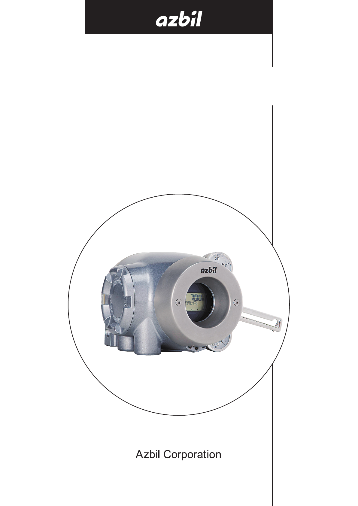
Smart Valve Positioner 700 Series
with HART Communication Protocol
Model AVP701/702
User's Manual
CM2-AVP702-2001
Page 2

Notice
• Make sure that this manual is delivered to the user of this product.
• It is prohibited to copy or reprint this manual in whole or in part without
permission.
• The contents of this manual are subject to change without notice.
• Although Azbil took all possible measures to ensure the accuracy of
this manual, contact us if you find any errors or missing information.
• Note that we cannot be held responsible for the results of customer
operation.
• HART® is a registered trademark of the FieldComm Group.
2014-2019 Azbil Corporation. All Rights Reserved.
©
Page 3

Introduction
Thank you for purchasing our AVP702 Smart Valve Positioner. The AVP702 (called “the
device” below) is a smart valve positioner that can be connected to the 4 to 20 mA loop.
The auto setup function makes it easy to set up the valve.
All adjustments and setup can be performed from the HART communication. The Local
User Interface (LUI), which consists of the LCD (liquid crystal display) and operation
buttons, facilitates monitoring of input signals, valve opening, pressure display, and other
items as well as basic adjustments.
In addition, the built-in pressure sensor can be used to measure the supply air pressure
and output air pressure. As a result, the device can not only perform self-diagnostics but
can also be combined with the control valve maintenance support system called “Valstaff”
in order to monitor the characteristics, operating status, and other data of the control
valve, helping to improve the maintenance efficiency of control valves. This instruction
manual describes how to handle the device. Read this manual to make full use of the
features of this product.
Scope of this manual and related documents
This document describes the functions and method of installation and adjustment of this
device. For details on HART communication, refer to
with HART Communication Protocol Model AVP701/702 HART Communication Manual
(No. CM2-AVP702-2002*).
For details on the control valve diagnostic items, refer to the “Smart Valve Positioner 700
Series Control Valve Diagnostic Function Manual” (No. CM2-AVP700-2003*).
* If you need the above documents, please contact one of our sales representatives.
Smart Valve Positioner 700 Series
i
Page 4
Safety precautions
■ Symbols
The purpose of the safety precautions listed here is to ensure the user uses the product safely
and correctly, to prevent harm to the user and other people and damage to property.
Make sure to obey the safety precautions.
Many different symbols are used in this manual.
Their appearances and meanings are as described below. Thoroughly understand the
explanation before starting to read the main text.
Warning
Cautions
■ Samplesymbols
This symbol indicates “warnings” and “cautions” that you must pay attention to when
handling the device.
This symbol indicates “prohibited” actions that must not be taken.
This symbol indicates “instructions” for the action that must be taken.
Wrong handling may cause the death or severe injury of the user.
Wrong handling may cause a minor injury to the user or damage to
equipment.
ii
Page 5
Precautions for safe work
Do not perform wiring with wet hands or while the device is energized. This may lead to
electric shock. Turn the power off before starting the work and work with dry hands or use
gloves.
Follow the work procedure defined in the explosion protection guidelines when performing the
power distribution work in an explosion-proof area.
For devices equipped with the pressure-resistant, explosion-proof specifications, do not open
the cover during operation (while the power is on).
Do not get on the installed device or use it as a step stool. This is dangerous because the
device may tip over.
Do not touch the device during operation without reason. This is dangerous because the
surface may be hot or cold depending on the usage environment.
Be careful not to touch the edge of the cover or the screw threads of the main unit when
opening the cover of the terminal box. You may be injured by these parts.
Warning
Cautions
Use a DC power supply with overload protection. Overload may cause smoke or fire.
If a tool or other item touches the glass part of the display, it may break, leading to an injury.
Be careful. Wear safety glasses during work.
This product is heavy. Be careful where you step and wear safety shoes during work.
Do not touch the feedback lever or other moving part while the device is operating. You may
be injured by getting your hand or other body part caught in them.
Properly use the power supply based on the specifications. Inputting a different power supply
may damage the device.
Use gloves and other protective equipment during work in a hot, cold, or other severe
environment.
Do not move the device close to a magnet or magnetic driver. The control valve may operate.
Apply the correct supply air pressure in acoordance with the specification of the device. The
overpressure may cause abnormal actions of the control valve or damage to the pressure
gauge.
iii
Page 6
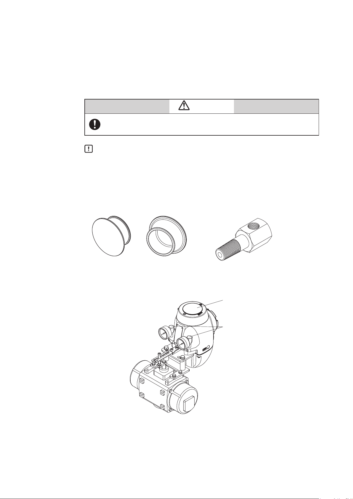
Unpacking, Verification, and Storage of Product
Unpacking
This device is precision measuring equipment. Carefully handle it to prevent
accidents or damage.
After unpacking, check that the items below are included.
• The device
• Feedback lever and hexagon socket bolts x 2
•
(4-mm) hexagon wrench x 1 (for feedback lever) (Included only when the device is shipped alone.)
• Regulator (KZ03) (optional)
• Mounting plate set (optional)
• Pressure-resistant packing cable adapter and pressure-resistant elbow (option for
explosion-proof specifications)
• Instruction manual (this document) (Included if specified at the time of purchase.)
• Extension lever and hexagon socket bolts x 2 (optional)
Specifications check
The specifications are shown on the nameplate of the main unit. Check that the
specifications are the same as what you specified. In particular, confirm the following points.
• Tag No. (TAG No.)
• Model (MODEL)
• Work No. (PROD.)
• Input current range (INPUT)
• Supply air pressure (SUPPLY)
• Explosion protection certification seal (for explosion-proof specifications)
Contact
Storage
WARNING
When using the device in an explosion-proof area, be sure to select the model
that satisfies the necessary explosion-proof requirements. Non-explosion-proof
products cannot be used in an explosion-proof area.
For inquiries about this device, please contact us.
When contacting us, let us know the model number and production number.
When storing the device after purchase, obey the following precautions.
• When storing the device before it has been used
1. Store the device as packed at shipment.
2. Store the device at an indoor location with little vibration or shocks and at
normal temperature and humidity (about 25°C, 65%).
• When storing the device after it has been used
1. Tightly secure the terminal box cover and block the conduit connection
port with tape to prevent humidity intrusion.
2. Block the three pneumatic piping connection ports (SUP , OUT1 and
OUT2) with tape to prevent humidity and dust intrusion.
3. Pack the device in the same way as at shipment.
Store the device at an indoor location with little vibration or shocks where it will not be
4.
exposed to rain or water and at normal temperature and humidity (about 25°C, 65%).
iv
Page 7

Table of Contents
Chapter 1 Structure of the 700 Series Control System ..............1-1
1-1 System Configuration ...............................................1-1
1-2 System Configuration without Motion Transmission ........................1-2
1-3 System Configuration with Motion Transmission ..........................1-2
1-4 Structure of the Device and Description of Each Part .......................1-3
1-4-1 Structure of the Device .........................................1-3
1-4-2 Structure of Terminal Box .......................................1-5
1-4-3 Display on the Local User Interface (LUI) ...........................1-7
Chapter 2 Installation of the 700 Series ..........................2-1
2-1 Usage Conditions ..................................................2-2
2-2 Selection Criteria for Installation Location ................................2-3
2-2-1 Selection Criteria for Installation Location ..........................2-3
2-2-2 Criteria for instrumentation air ...................................2-3
2-3 Installation Procedure ...............................................2-5
2-3-1 Mounting the 700 Series onto the Actuator ..........................2-5
2-3-2 Pneumatic Piping Connection ...................................2-12
2-3-3 Electrical Wiring Connection ....................................2-15
2-3-4 Input Signals and Travel Transmission Power ......................2-17
2-3-5 Cables .....................................................2-18
2-4 Cable gland and flameproof universal elbow for TIIS Flameproof apparatus ....2-20
Chapter 3 Operation of the 700 Series ...........................3-1
3-1 Local User Interface (LUI) ............................................3-2
3-2 Adjustment before Operation .........................................3-5
3-2-1 Auto Setup ..................................................3-5
3-2-2 Zero Span Adjustment .........................................3-9
3-2-3 Supply Bypass ..............................................3-12
3-2-4 Control Parameters ...........................................3-13
3-2-5 Password ..................................................3-15
3-3 Starting Operation .................................................3-16
3-3-1 Preoperation Check ..........................................3-16
Chapter 4 Operation with HART Communication ..................4-1
4-1 Operation with HART Communication ..................................4-1
4-2 Setup and Adjustment of Device .......................................4-2
4-2-1 Process Variables .............................................4-2
4-2-2 Auto Setup ..................................................4-3
4-2-3 Input Range .................................................4-5
4-2-4 Valve System ................................................4-5
4-2-5 Control Configuration ..........................................4-6
4-2-6 Input Characterization ..........................................4-8
4-2-7 Travel Cutoff .................................................4-8
4-2-8 Units .......................................................4-9
4-2-9 Travel Calibration ............................................4-10
4-2-10 Input Calibration .............................................4-12
4-2-11 Pressure Sensor Adjustment ...................................4-12
4-2-12 Simulation .................................................4-12
4-2-13 Adjustment of EPM Drive Signal (Pneumatic Modules) ...............4-13
4-2-14 Restore factory settings .......................................4-13
4-2-15 Operator Action Records ......................................4-13
v
Page 8

4-2-16 Real Time Clock .............................................4-13
4-2-17 Password ..................................................4-13
4-2-18 Device Information ...........................................4-14
4-2-19 Option ....................................................4-16
4-2-20 Diagnostic Messages .........................................4-17
4-2-21 Control Valve Diagnostic Messages ..............................4-19
Chapter 5 Troubleshooting ....................................5-1
5-1 Troubleshooting ...................................................5-2
5-1-1 The Device Does Not Operate. (There Is No Output Air Pressure.) .......5-2
5-1-2 The Control Valve Operates Abnormally (There Is Output Air Pressure.) ...5-2
5-1-3 Failure to communicate with the communicator ......................5-2
5-1-4 Adjustment Procedure When Hunting Occurs .......................5-3
5-1-5 Auto Setup Failure ............................................5-4
5-2 Description of Messages .............................................5-5
Chapter 6 Maintenance .......................................6-1
6-1 A/M Switch .......................................................6-2
6-2 Replacement of Filter and Maintenance of Flow Restriction ..................6-4
6-3 Cleaning the Flapper ................................................6-5
6-4 Adjusting the Pilot Relay .............................................6-6
6-5 Insulation Resistance Test ...........................................6-7
6-6 Adjustment Procedure When Using the Device with the Booster Relay Attached . 6-8
6-7 List of Default Values for Internal Data ..................................6-9
6-8 Internal Block Diagram of the 700 Series ...............................6-10
6-9 Resale Parts .....................................................6-11
6-9-1 Procedure to Change Switch Block ..............................6-15
6-9-2 Procedure to Change Pilot Relay ................................6-16
Chapter 7 Notes on the Explosion-Proof 700 Series ...............7-1
7-1 TIIS Flameproof Model ..............................................7-2
7-2 ATEX Flameproof and Dust Ignition Protection. . . . . . . . . . . . . . . . . . . . . . . . . . . . 7-3
7-3 IECEx Flameproof and Dust Ignition Protection ...........................7-5
7-4 FM Explosionproof / Dust Ignition Protection .............................7-7
7-5 FM Intrinsically safe (ic) and Nonincendive ..............................7-8
7-6 FMC Explosionproof / Dust Ignition Protection ...........................7-13
7-7 NEPSI Flameproof / Dust Ignition Protection ............................7-14
7-8 KOSHA Flameproof ...............................................7-16
7-9 INMETRO Flameproof / Dust Ignition Protection .........................7-17
7-10 EAC Flameproof ..................................................7-19
7-11 ATEX Intrinsic Safety and Dust Ignition Protection ........................7-20
7-12 IECEx Intrinsic Safety and Dust Ignition Protection .......................7-21
Appendix A LUI Display Example ................................A-1
Appendix B Menu List ..........................................B-1
Appendix C Specification .......................................C-1
Appendix D Model Selection ....................................D-1
Appendix E Outline Dimensional Drawing .........................E-1
vi
Page 9
Chapter 1 Structure of the 700 Series Control System
This chapter describes the device configuration of the control system that uses the
device.
• Description of the configuration of the input/output system in the device
• Description of the structure of the main unit of the device and the name and function of
each part
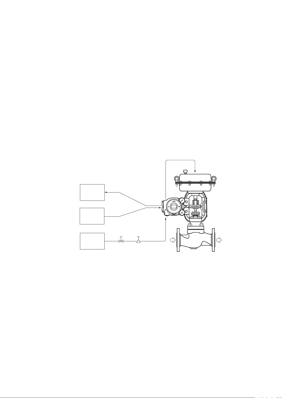
1-1 System Configuration
This device is a smart valve positioner that can be connected to the 4–20 mA DC signal
lines of the controller output. It makes various adjustments using electricity, so the
relationship between input signals and control valve travel can be set to any desired
value. In addition, by connecting the device using four lines, the control valve travel is
transmitted to the host monitoring system as a 4–20 mA DC analog signal. (Only the
AVP701 model supports valve travel transmission.)
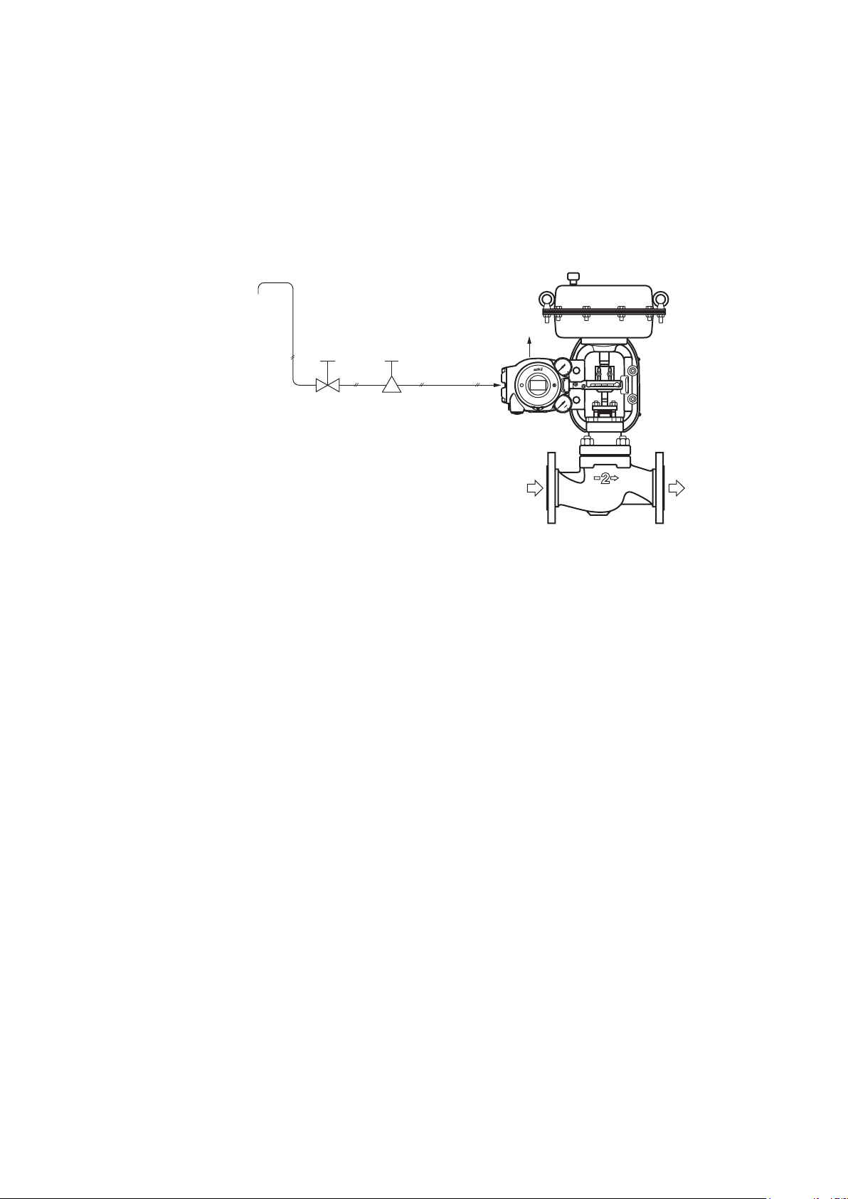
Air to the actuator
Host
monitoring
system
Host controller
Air supply
system
DC4–20mA analog signal
(AVP701)
DC4–20mA analog signal
Shutoff Solenoid valve
with filter
valve
Device
Supply air
Control valve
Figure1-1 Concept Diagram of the 700 Series Control System
Process fluid
1-1
Page 10
1-2 System Configuration without Motion Transmission
This shows the configuration for a system that does not use the motion transmission
function of this device (model AVP702).
Host
controller
HART configuration
tool
DC4–20mA
HART Modem
I IN
I IN
Device
Figure1-2 System Configuration without Motion Transmission (Model AVP702)
1-3 System Configuration with Motion Transmission
This device (model AVP701) has a function for motion transmission of the control valve.
To output the travel signal to the host monitoring device using analog values, configure
the system with motion transmission. Normally, the travel from fully closed to fully open
are output as 4–20 mA DC.
This shows an example of a system configuration for outputting valve travels detected
with this device as 4–20 mA DC analog signals.
With this system configuration, analog signals are output directly to the higher-order host
monitoring system from this device.
250Ω
Host
monitoring
system
(current input)
Host
controller
*1: For the detailed information of the power supply and resistor, please
refer to the figure 2-18 of 2-3-4 Input Signals and Travel Transmission
Resistor
*1 *1
Analog signal
DC4–20mA
DC4–20mA
DC24V
Power supply
HART Modem
Device
HART configuration tool
Figure1-3 System Configuration with Motion Transmission (Model AVP701)
1-2
Page 11
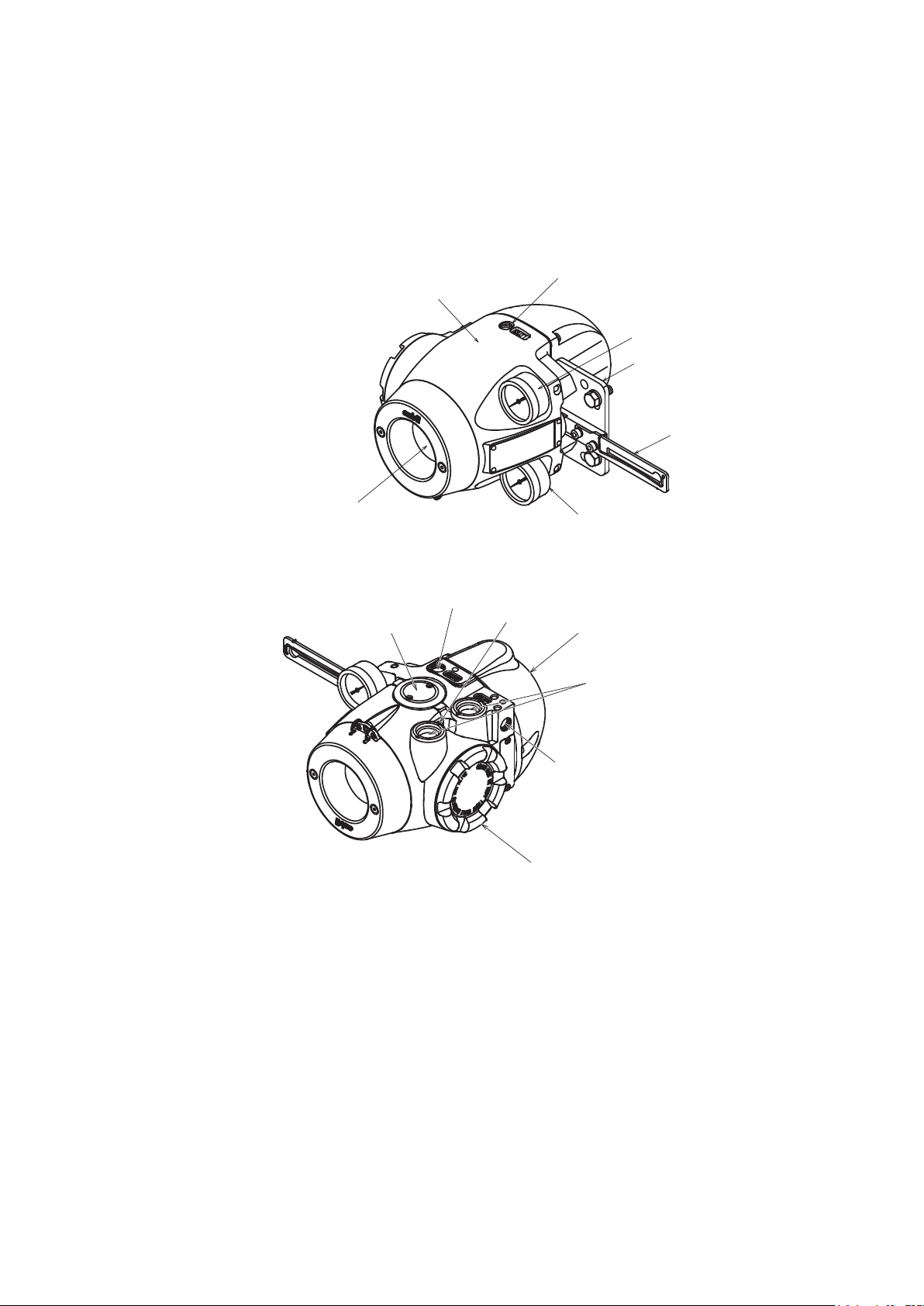
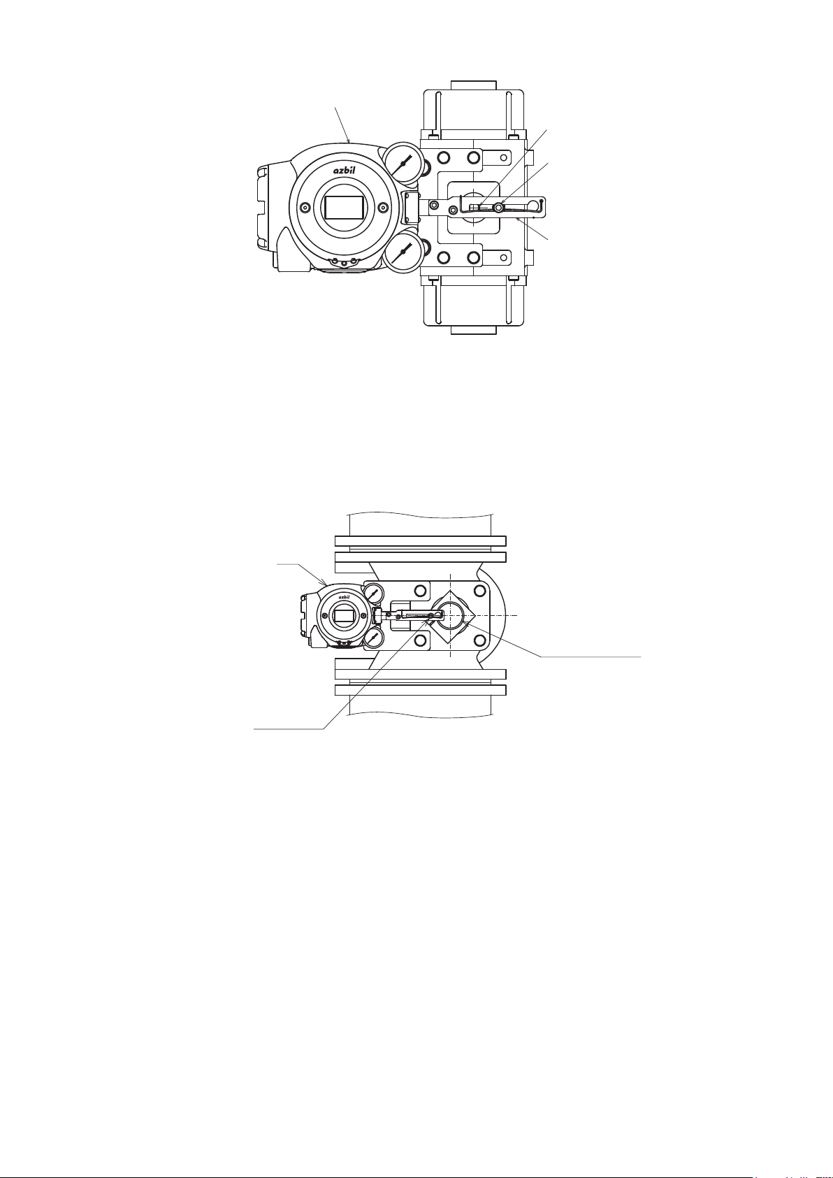
1-4 Structure of the Device and Description of Each Part
1-4-1 Structure of the Device
1) Major components
The structure of the main unit of the device is shown in the figure below.
Output air connection port (OUT1)
Main unit
Output air pressure gauge
Mounting plate (optional)
Feedback lever
Local user
interface (LUI)
Exhaust cap
Supply air pressure gauge
Figure1-4 Structure of the Device (Upper)
Output air connection port (OUT2)
External grounding terminal
Pilot relay cover
Electrical conduit connection port
Supply air connection port (SUP)
Terminal box cover
Figure1-5 Structure of the Device (Lower)
1-3
Page 12

2) Name and description of each part
The table below describes each part.
Table 1-1 Description of Each Part
Name Description
Main unit
Pilot relay cover
Auto/Manual (A/M) switch
Feedback lever
Local user interface (LUI)
Supply air pressure gauge - Indicates the pressure of supply air.
Output air pressure gauge - Indicates the pressure of output air.
Supply air connection port (SUP)
Output air connection port (OUT1)
Output air connection port (OUT2)
Mounting plate (optional)
- Houses electronic circuits, an electro-pneumatic transducer (EPM), a
position sensor (VTD), and a pressure sensor.
- Cover of the pilot relay that amplifies the air signal from the EPM
(electro-pneumatic transducer) and transduces it into the air signal
sent to the actuator.
- When you must adjust the balance pressure to switch between the
pilot relay for the single-acting actuator and the pilot relay for the
double-acting actuator, remove this cover.
- This switch is used to switch how the output air between the auto
operation status and the manual operation status is controlled.
This switch is built into the pilot relay. This switch can be seen by
removing the pilot relay cover.
- Extracts and transmits the movement of the control valve lift to the
VTD (position sensor).
- The LUI allows you to adjust the zero span, perform auto setup, and
manually operate the device with the LCD (liquid crystal display) and
operation buttons without using the communicator.
- Supply air is input to this port.
- “SUP” is displayed at this port.
- Output air is sent out of this port to the actuator.
- “OUT1” is displayed at this port.
- Output air is sent out of this port to the actuator.
- This port is blocked with a blind plug in the single-acting actuator.
- OUT2 is displayed at the output port for the double-acting actuator.
- The mounting plate is used to mount the device onto the actuator.
- The shape of the mounting plate differs depending on the
specifications (actuator model).
1-4
Page 13
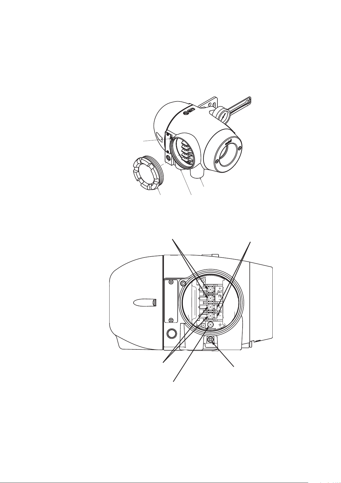
1-4-2 Structure of Terminal Box
1) Major components
This contains the input signal (controller output) terminal, output signal (motion
transmission) terminal, and internal ground terminal.
The structure of the terminal box is as shown below.
Lock screw
Terminal
box cover
Conduit connection port (1)
Conduit connection port (2)
Figure1-6 Structure of Terminal Box
Terminal for output signals
M4 screw
HART check pin
Terminal for input signals
M4 screw
Terminal for internal grounding
M4 screw
Figure1-7 Terminal Block in the Terminal Box
1-5
Terminal for external grounding
M4 screw
Page 14
2) Name and description of each part
The table below describes each part of the terminal box.
Table 1-2 Description of Each Part
Name Description
Terminal box cover
Lock screw - Used to secure the terminal box cover.
Terminal for input signals
Terminal for output signalsl
Internal grounding terminal
Conduit connection port (1) - Service entrance for a cable.
Conduit connection port (2)
Check pin for HART communication
- Lid of terminal box.
- This cover has a pressure-resistant explosion-proof structure.
- Shown as IN.
- Connects the signal cable from the host controller.
- Shown as OUT.
- Connects the signal cable for motion transmission.
- The AVP702 model (without motion transmission) does not have
the terminal screws.
- Internal terminal for grounding. The cable for grounding is
connected to this terminal.
- Service entrance for a cable.
- This entrance is normally blocked with a blind plug.
- By connecting the connection hook for the setting device
communication cable to this pin, it is possible to communicate
with this device.
Warning
When using a pressure-resistant explosion-proof model in a dangerous place,
be sure to use the specified cable adapter for pressure-resistant packing for
the conduit connection port. Securely close the terminal box cover all the way.
Then, rotate the lock screw counterclockwise to secure the terminal box cover.
Handling Precautions:
Ground either the external or internal grounding terminal according to the
specifications. Be careful not to ground the device at two points.
1-6
Page 15
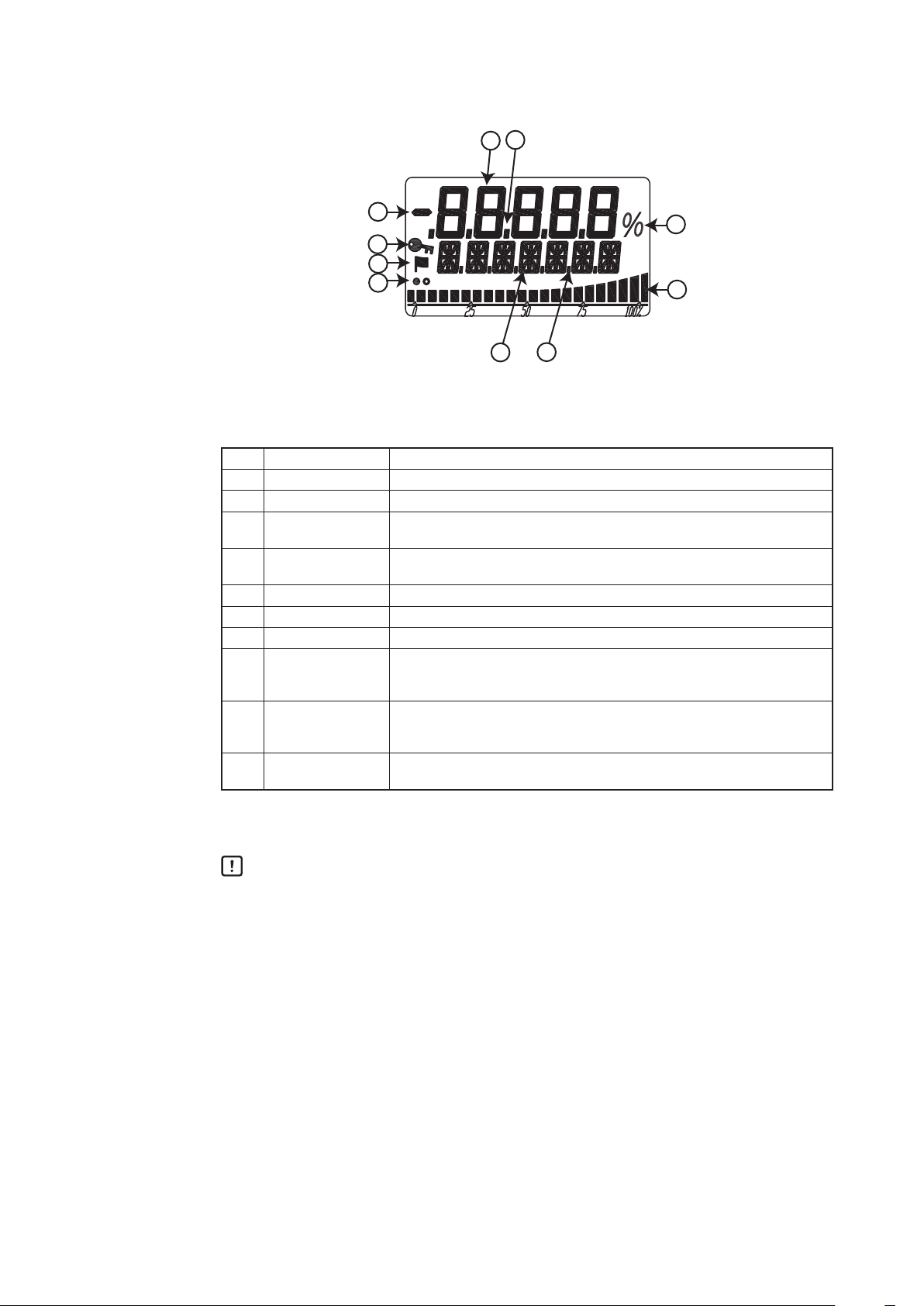
1-4-3 Display on the Local User Interface (LUI)
3
1
2
8
9
10
5
4
6
7
Figure1-8 Segments on the LCD
Table 1-3 Description of Each Part
No. Displayed element Main display
(1) 7 segments (5 digits) Displays the main numerical values such as the specified opening.
(2) Minus sign Displays the sign for the 7-segment number.
Decimal point
(3)
(five places)
16 segments
(4)
(7 digits)
(5) Dot (6 places) Displays the 16-segment auxiliary display, separator, or other data.
(6) Percentage Displays %.
(7) Bar graph (22 bars) Displays the bar graph in percentage at a set point, etc.
(8) Key mark
(9) Flag mark
(10) Display refresh mark
Displays the decimal point for the 7-segment number.
Displays the unit, status, or other data.
On: LUI operation is unavailable.
Off: LUI operation is available.
Blinking: LUI is in operation.
When the self-diagnostic alarm is activated, the key mark is displayed.
For detailed information of the alarms,please refer to the status monitor of
page 3-4.
Display during operation
White and black circles alternately blink.
For a display example, refer to "LUI Display List" in Appendix A.
Handling Precautions:
The LUI buttons may not respond well near an electromagnetic inductor (such as
a large transformer or high-frequency furnace).
Remove sand, dust, and other foreign objects from the rubber parts of the
operation buttons before operating the LUI. Operating the LUI with foreign
objects on it may damage the rubber parts.
Do not pull the rubber parts of the operation buttons. This may deteriorate the
sealability, possibly causing malfunction.
1-7
Page 16

1-8
Page 17
Chapter 2 Installation of the 700 Series
This chapter describes the usage conditions, installation, piping, and wiring of the device.
Precautions for safe work
Warning
Do not perform wiring with wet hands or while the device is energized. This may lead to
electric shock. Turn the power off before starting the work and work with dry hands or use
gloves.
Follow the work procedure defined in the explosion protection guidelines when performing the
power distribution work in an explosion-proof area.
For devices equipped with the pressure-resistant, explosion-proof specifications, do not open
the cover during operation (while the power is on).
Cautions
Do not get on the installed device or use it as a step stool. This is dangerous because the
device may tip over.
Do not touch the device during operation without reason. This is dangerous because the
surface may be hot or cold depending on the usage environment.
Be careful not to touch the edge of the cover or the screw threads of the main unit when
opening the cover of the terminal box. You may be injured by these parts.
Use a DC power supply with overload protection. Overload may cause smoke or fire.
If a tool or other item touches the glass part of the display, it may break, leading to an injury.
Be careful. Wear safety glasses during work.
This product is heavy. Be careful where you step and wear safety shoes during work.
Do not touch the feedback lever or other moving part while the device is operating. You may
be injured by getting your hand or other body part caught in them.
Properly use the power supply based on the specifications. Inputting a different power supply
may damage the device.
Use gloves and other protective equipment during work in a hot, cold, or other severe
environment.
Do not move the device close to a magnet or magnetic driver. The control valve may operate.
Apply the correct supply air pressure in acoordance with the specification of the device. The
overpressure may cause abnormal actions of the control valve or damage to the pressure
gauge.
2-1
Page 18

2-1 Usage Conditions
The device must be installed in the location, which satisfies the following conditions.
Also, the divice must be used in accordance with its specification.
General model °C 23 ± 2 -40 to +80 -40 to +80 -40 to +70
TIIS flameproof
model
ATEX/IECEx/
FM/FMC/NEPSI/
KOSHA/EAC/
Operating
temperature
range
Vibration
Friction of applied valve % 3 to 20 3 to 20
Supply air pressure Ps
(140 kPa ≤ Ps ≤ 700 kPa)
Installation orientation
Each operating condition is defined as follows.
- Basic operating condition: Range in which the accuracy is guaranteed
- Normal operating condition: Range in which the positioner normally operates
Marginal operating condition
-
- Transportation condition: Environment condition range in which the non-operating device is not
INMETRO
flameproof
model
FM Intrinsically
Safe (ic) and
Nonincendive
ATEX/IECEx
intrinsically safe
model
LUI °C 23 ± 2 0 to +50 -40 to +80 -40 to +70
Input current mA 4 to 20 3.84 to 21.6
Amplitude
Acceleration
Humidity range %RH 50 ± 10 5 to 100 5 to 100 5 to 100
Table 2-1 Range of Usage Conditions
Units
Basic
operating
conditions
Normal
operating
conditions
Marginal
operating
conditions
°C 23 ± 2 -20 to +55 -20 to +55 -40 to +70
°C 23 ± 2 -30 to +75 -30 to +75 -40 to +70
°C 23 ± 2 -24 to +75 -24 to +75 -40 to +70
°C 23 ± 2 -40 to +60 -40 to +60 -40 to +70
0 to 3.84
Note 5
21.6 to 24
Note 1
Note 1 Note 2
mm
m/s
p-p
2
0
0
15/(5 to 8 Hz) 15/(5 to 10 Hz) 15/(5 to 10 Hz)
20/(8 to 400 Hz)
40/(10 to 400 Hz) 40/(10 to 400 Hz)
0 to 3
20 to 100 ―
kPa Ps ± 1% 140 to 700 0 to 710 ―
Note 3
° ±1
Note 4
±180 ±180 ±180
: Range in which performance is not guaranteed but the device can be without
being permanently damaged
permanently damaged during transportation
Transportation
conditions
―
Note 1: Vibration conditions when the positioner cover is positioned at the center front.
Note 2: The pressure gauge is not applied.
Note 3: The slope characteristics are not included.
Note 4: The status where the drive shaft of the direct-acting actuator is perpendicular to the ground and that is
used as the reference.
Note 5: In the range of 3.5 mA to 3.84 mA, HART communication is possible though the operation of the
positioner is not guaranteed. (The output air pressure assumes that the power is cut. The pressure
sensor value is not guaranteed.)
2-2
Page 19

2-2 Selection Criteria for Installation Location
The device is designed to withstand severe conditions, but the installation location should
be selected according to the criteria described below to maximize performance.
2-2-1 Selection Criteria for Installation Location
Install the device in a location that satisfies all of the following conditions.
• Operating temperature range that conforms to the explosion protection rules
• Relative humidity: 5 to 100%RH
• Ambient temperature change rate: ±20°C/hr or slower
• Electromagnetic induction: 400 A/m or less (Avoid places near a large transducer,
high-frequency furnace, or other such equipment.)
• Do not use a transceiver near the device.
2
• Vibration: 20 m/s
(The vibration conditions defined for the device are the vibrations at the positioner
part.)
(5 to 400 Hz) or less
2-2-2 Criteria for instrumentation air
The device employs a nozzle flapper structure in the electropneumatic transduction
section. If instrumentation air is contaminated (includes oil, water, or other substance),
the positioner function of the device may not function properly or an irrecoverable failure
may occur. Therefore, the quality of instrumentation air supplied to the device is defined
as follows.
• Solid material : No particles with a diameter larger than 3 μm.
• Oil : Less than 1 ppm.
• Supply air humidity : The dew point temperature is at least 10°C lower than that of the device.
(This criterion is based on Japanese Industrial Standards JIS C 1805-1(2001).)
Select a compressor and main line or terminal-installation type compressed air purifier by
referring to the above specifications.
(1) Compressed air purifier for the main line
Select a compressed air purifier for the main line, such as a main line filter or microalescer, to satisfy the above specifications.
Domestic compressed air purifier manufacturers of Japan: SMC Corporation and CKD
Corporation
(2) Compressed air purifier to be installed on the terminal
If an air purifier cannot be installed on the main line due to installation of a control
valve or for other reasons, use an compressed air purifier that can be installed on the
terminal in order to satisfy the above specifications.
2-3
Page 20

<Example devices>
- Products from SMC Corporation
Mist Separator AM150 or AM250 Series
(Filtering level: 0.3 μm, Secondary oil mist concentration: 1.0 mg/m
- CKD Corporation
Oil mist filter
M1000 or M3000 Series
3
Mantle S Type (Filtering level: 0.3 μm, Remaining oil: 1.0 mg/m
)
Handling Precautions:
Select a compressed air purifier with specifications suited to the usage
conditions. Even when you install the above oil removal equipment, it is
necessary to properly inspect and maintain the air circuit section for long-term
stable operation. Install the oil removal equipment before use and perform
periodic inspection and maintenance.
The warranty is void if the device fails because the quality of the above
instrumentation air was not sufficient.
3
)
2-4
Page 21
2-3 Installation Procedure
2-3-1 Mounting the 700 Series onto the Actuator
The device is a smart valve positioner for use with a control valve that uses a directacting or rotary actuator. The main unit of the device weighs approximately 4.2 kg.
The basic mounting procedure is the same as that for conventional electropneumatic
positioners.
Cautions
Be careful not to get injured by sharp parts such as the edge of the main unit or actuator
or screw threads during mounting.
The type of mounting plate, mounting method, and mounting procedure differ depending
on the actuator model to be mounted in the device.
If the device is not properly mounted, not only will the device not be able to operate at its
true performance but it may be damaged or fail. Pay attention to the following points.
- The mounting plate and its accessories differ depending on the specifications
(actuator model). Be sure to use the appropriate mounting plate and accessories for
the actuator to be mounted.
- When installing the control valve, ensure as much surrounding space as possible
and put the device in the correct orientation taking maintainability (such as piping,
wiring, and adjustment) into consideration.
- Deliver the device to the installation location in the packaged state if possible.
- Do not apply excessive force to the feedback lever during mounting.
- Do not bend the feedback pin.
- Do not block the exhaust port located underneath.
-
Install the device so that the electrical conduit connection port does not face upward.
- Securely tighten bolts.
- If the model KZ03 pressure regulator with filter is installed with the device, install
with the drain of the KZ03 facing downward. If the KZ03 cannot be attached
vertically (with the drain facing downward), install it separated from the AVP with the
proper orientation.
- In order to avoid the possibility of rainwater entering the pressure gauge, install the
gauge such that it does not face upward or downward. In addition, the pressure
gauge has a rainwater drain on its underside, so install the gauge with this hole
facing downward.
- If you install this device with the LCD facing upwards, use the LCD cover and
pressure gauge elbows as necessary, depending on the circumstances. For details,
refer to 6) below, “Installing the device with the LCD facing upwards.”
2-5
Drain plug
Page 22
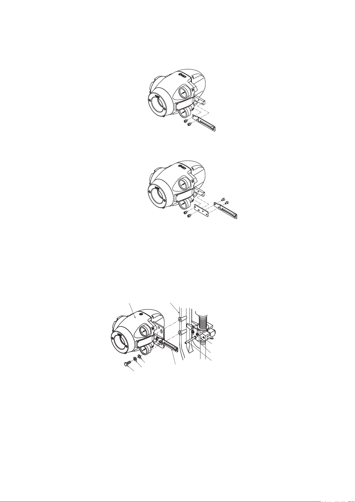
1) Mounting the feedback lever
Hexagon socket flange bolts (x 2)
Yoke
AVP
Hexagonal bolt
Assemble the feedback lever from the front of the main unit of the device using the two
included hexagon socket bolts.
Figure 2-1 Mounting Procedure for Feedback Lever
Assemble the extension lever as shown in the figure below if necessary.
Figure 2-2 Mounting Procedure for Extension Lever
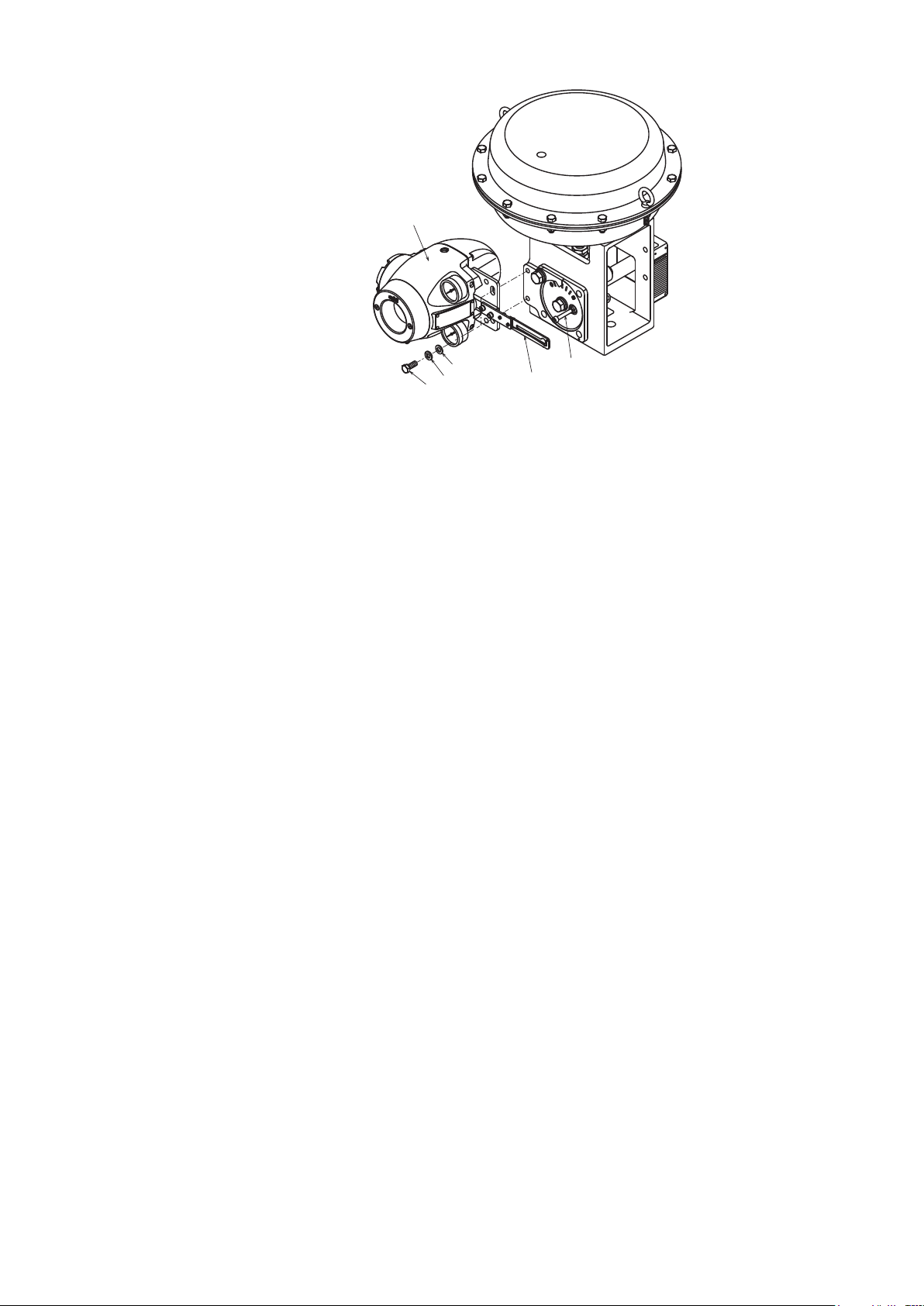
2) Mounting example
A typical mounting method is shown in the figure below. If your actuator is not shown in
the figure below, refer to the assembly diagram included with the device.
[Direct-Acting Actuator HA2 to 4, PSA1 to 4, 6, VA1 to 6 from Azbil Corporation]
Connector pin assembly
Plain washer
Spring washer
Feedback lever
Figure 2-3 Mounting Procedure for Direct-Acting Actuator HA2 to 4, PSA1 to 4, 6, VA1
to 6 from Azbil Corporation
Feedback pin
[RSA1, 2, VR3 actuator from Azbil Corporation]
2-6
Page 23
AVP
Hexagonal bolt
Plain washer
Spring washer
Feedback pin
Feedback lever
Figure 2-4 Mounting Procedure for RSA1, 2, VR3 Actuator from Azbil Corporation
2-7
Page 24
[Example of double-acting rotary cylinder actuator]
Hexagonal bolt
SpacerAVP
Spring washer
Hexagonal bolt
Arm
Spring washer
Spring
washer
Hexagonal nut
Feedback lever
Feedback pin
Figure 2-5 Mounting Procedure for Double-Acting Rotary Cylinder Actuator
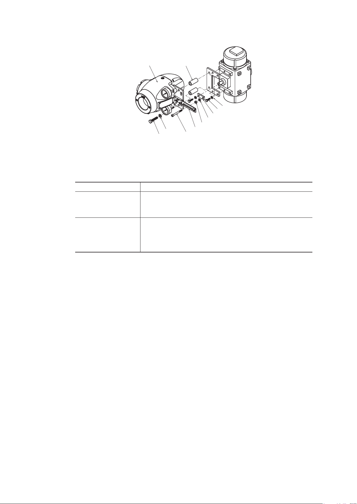
3) Mounting procedure
The procedure for mounting the feedback lever onto the actuator is shown below.
Step Work
Tightly secure the mounting plate by inserting hexagonal bolts
1
2
(M8×20) with spring washers into the (two) screw holes at the
rear of the device.
Tightly secure the device (mounting plate) onto the mounting
seat of the actuator by using bolts and washers. At this time,
insert the actuator feedback pin into the slotted hole of the
feedback lever in the device.
2-8
Page 25
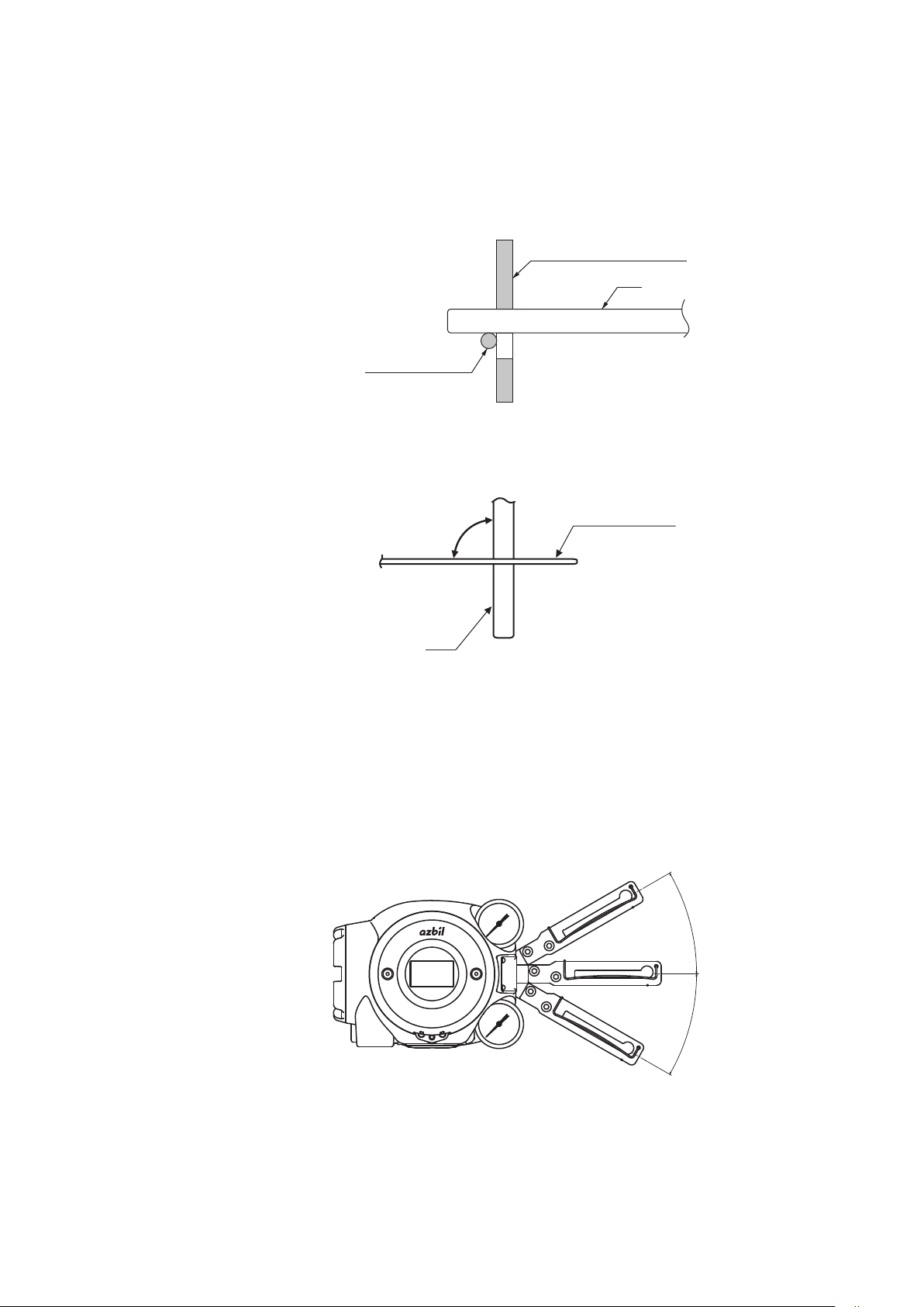
4) Connection of feedback pin and feedback lever (1)
Spring (cross section)
Pin
30°
30°
There are several points to be careful of when connecting the feedback lever to the
device and the actuator feedback pin. Connect correctly.
- Only a pin with a diameter of 6 mm can be used.
- Insert the pin between the guide and the spring.
Feedback lever (cross section)
Pin
Figure 2-6 Connection of Feedback Lever and Feedback Pin
- Make the feedback lever perpendicular to the pin when viewed from the above.
90°
Feedback lever
Figure 2-7 Angle between Feedback Lever and Pin
- Mount the lever so that it is horizontal when opened by 50%.
- The allowable rotation angle of the feedback lever is horizontal ± 30°. If the angle
exceeds ±30°, the self-diagnostic function detects Valve Travel Detector Out of Range
and the device will not operate normally. (The accuracy is guaranteed when the
rotation angle is between ±4° and ±20°.)
Figure 2-8 Operation Angle of Feedback Lever
- When assembling the lever onto a rotary cylinder so that the shaft of the rotary
cylinder is positioned between the feedback pin and the 700 Series as shown in the
figure below, select Rotary/90° (for 90°) or Rotary/other (for angles other than 90°) as
the Actuator Type according to the rotation angle.
2-9
Page 26
Shaft of rotary cylinder
AVP
Feedback pin
Feedback lever
Figure 2-9 Connection of the Rotary Cylinder to the Feedback Pin and Feedback
Lever
- When the rotary cylinder is large and the lever is assembled so that the feedback pin
is positioned between the 700 Series and the shaft of the rotary cylinder as shown
in the figure below, select Rotary (sub)/90° (for 90°) or Rotary (sub)/other (for angles
other than 90°) as the Actuator Type according to the rotation angle.
AVP
Shaft of rotary cylinder
Feedback pin
Figure 2-10 Feedback Pin and Feedback Lever Connection for Rotary Cylinder (Large
Cylinder)
5) Maintenance space behind the device
The device has a nozzle flapper mechanism in the back of the main unit. When cleaning
the flapper, you must remove the pilot relay cover secured to the back with three screws.
Design the clamp and feedback mechanism to ensure maintenance space for cleaning.
2-10
Page 27
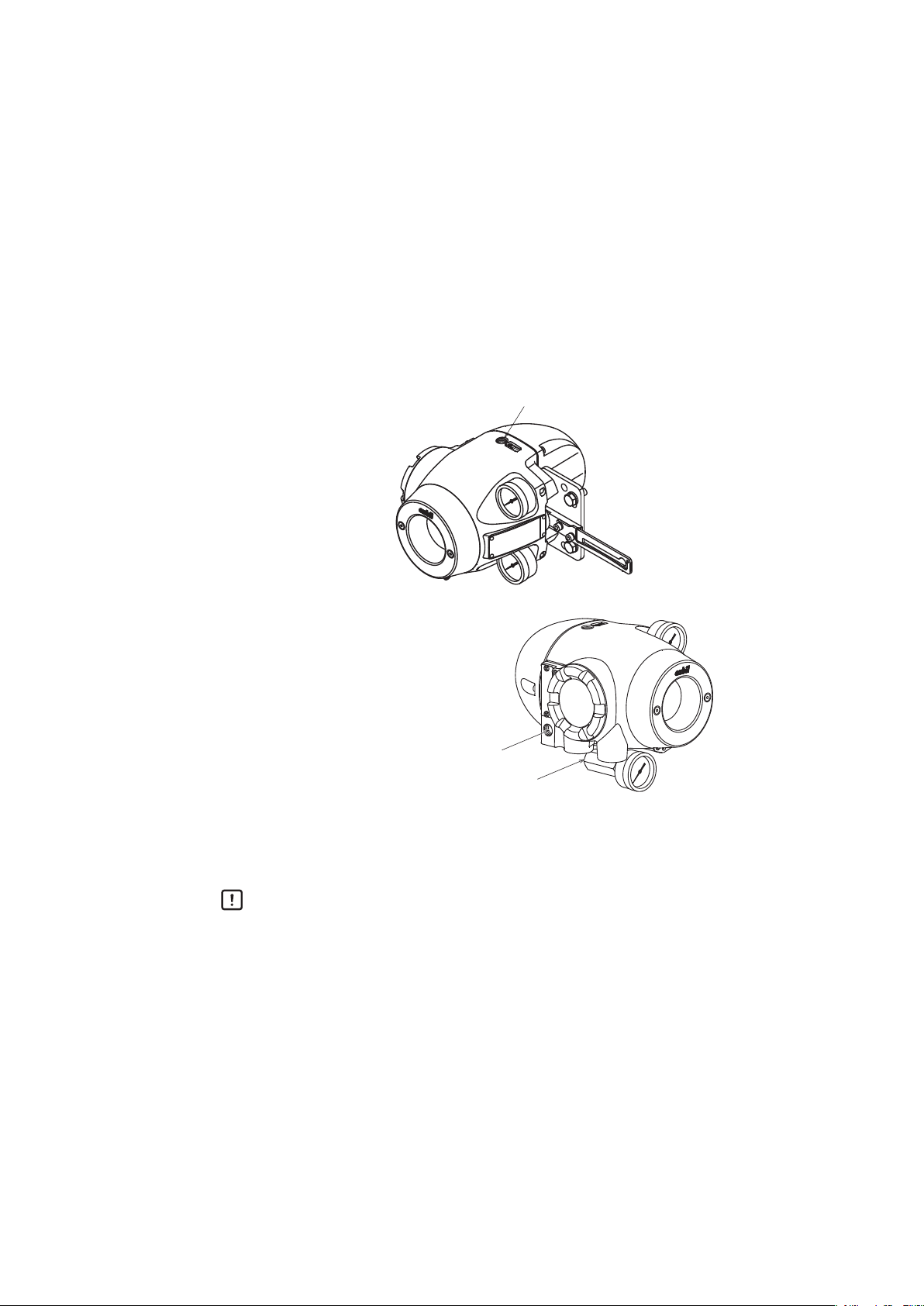
6) Installing the device with the LCD facing upwards
If you install the device with the LCD facing upwards, use the accessories below as
required depending on the circumstances. (Refer to 6-9, “Resale Parts.”)
• LCD cover (material: silicone rubber)
This cover reduces deterioration of the LCD due to sunlight (ultraviolet radiation). Use the
cover if the device is used in a place with strong sunlight (outdoors, etc.).
Cautions
Before mounting or removing the LCD cover, it is necessary to remove the face cover
from the main unit. Take care as you work not to touch sharp parts of the face cover,
such as the rim. You might be injured.
Handling Precautions:
Remove the face cover when checking the LCD.
• Pressure gauge elbows
The elbows are for mounting the pressure gauges if the device is installed in a place
with direct exposure to rainwater (outdoors, etc.). (If the pressure gauges are installed
facing upward, they will be damaged by rainwater.
Front Back
Figure 2-11 LCD cover Figure 2-12 Pressure gauge elbow
LCD cover
Pressure gauge elbow
Figure 2-13 Example of LCD cover and pressure gauge elbow mounting
2-11
Page 28
2-3-2 Pneumatic Piping Connection
Supply air
This section describes how to supply the air for the device to drive the actuator.
1) Air supply system
Supply air must be clean and dry to stably use the device for a long time. A typical
example of an air supply system is shown in the figure below.
Shutoff
valve
Regulator
with filter
Supply air piping
Output air
piping
Figure 2-14 Air Supply System
2) Supply air
Use supply air that conforms to the instrumentation air standards (on page 2-2).
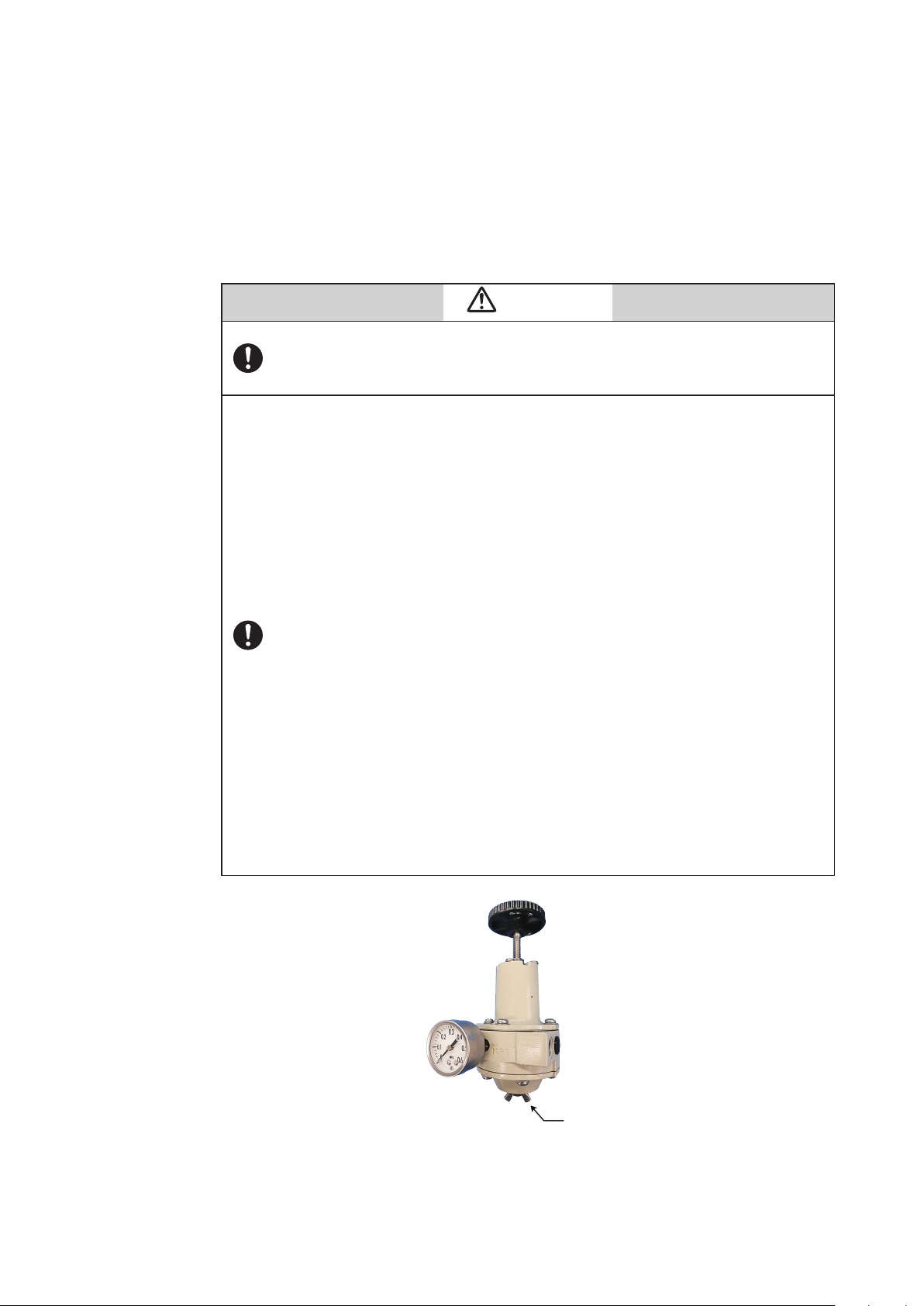
3) Regulator with filter
• The regulator with filter is used to adjust the pressure of the supply air to the device.
• Install this valve as close to the main unit of the device as possible.
• The control valve can be manually operated by using the A/M switching function. (The
double-acting actuator does not support manual operation.)
• Use a 3-μm or finer filter.
• The filter removes solid materials from supply air.
• If the filter is not equipped, separately insert a (3-μm or finer) filter immediately before
the regulator.
• Install the regulator so that the drain faces downward.
• If you select the built-in Azbil regulator KZ03, the filter is built into the device before
shipment.
4) Shutoff valve
• The shutoff valve is used to temporarily stop supplying air to the device.
• With this valve, the device or control valve can be removed without having to stop the
whole air supply system during maintenance or other operations.
2-12
Page 29
5) Piping
Output air connection port (OUT1)
Supply air connection port (SUP)
Rc1/4 or 1/4NPT
• Use piping with an inside diameter of 6 mm.
• When using the device in a corrosive atmosphere, select piping appropriate to the
environment of the installation location. For example, you may use the vinyl-coated
copper pipe.
• To prevent air leaks, be sure to use a fitting that is appropriate for the pipe.
6) Connection positions
The positions of the supply air connection port and output air connection port are shown
in the figure below. Select the dimensions of the connection port screws according to the
specifications.
Rc1/4 or 1/4NPT
Handling Precautions:
Output air connection port (OUT2)
(For double-acting actuator)
Figure 2-15 Pneumatic Piping Connection
When connecting the electromagnetic valve for emergency shutoff, air
valve, or other part, install it between the output air connection and the
actuator rather than the supply air connection side of the device.
2-13
Page 30
7) Mounting procedure
The procedure for connecting pneumatic piping to operate the device is shown below.
Step Work
Connect the joint for piping to the connection port using seal
tape.
Handling Precautions:
1
- Use seal tape as the seal material. Avoid using solid
or liquid seal material if possible.
- Do not let the seal tape get in the piping.
- If you do use a liquid seal, make sure that no drops
of the seal material get in the piping.
Connect the supply and output pipes to each joint in
consideration of the arrangement of the piping.
Handling Precautions:
- For the double-acting actuator, the connection
between output air connection ports OUT1 and
2
3 After all piping is complete, make sure that air does not leak.
OUT2 and the actuator is determined by the
valve operation. Check the valve operation before
connecting pipes.
- Sufficiently flush piping before connection to prevent
burrs on the piping or other foreign objects from
getting in the piping.
- Keep the output air piping as short as possible.
2-14
Page 31

2-3-3 Electrical Wiring Connection
This section describes the methods for electrical wiring for signal input from the controller
and signal output to the monitoring system.
Turn the power off before starting wiring work. Otherwise, electric shock may occur.
When using the explosion-proof 700 Series in a dangerous place, be sure to connect the
wiring while following “Chapter 7 Precautions for the Explosion-Proof 700 Series.”
Be sure to perform grounding work following the electrical work guidelines in each region.
Handling Precautions:
Be sure to attach a blind plug to the unused conduit connection port so that it is
completely covered.
Warning
Cautions
1) Connection positions
The figure below shows the terminal block in the terminal box.
Terminal for output signals
M4 screw
Terminal for input signals
M4 screw
HART check pin
Terminal for external grounding
M4 screw
Terminal for internal grounding
M4 screw
Figure 2-16 Terminal Block in the Terminal Box
2-15
Page 32

2) Terminalforexternalgrounding
Connect the external grounding terminal to the case with two washers as follows.
Cable lug
Washer
Washer
Figure 2-17 Connection of External Grounding Terminal
3) Without motion transmission (model AVP702)
Remove the terminal box cover and connect the wires as shown in the figure below.
Controller
Ground
Figure 2-18 Electrical Wiring without Motion Transmission (2-conductor cable)
Use only one of the two ground terminals (internal or external) and perform the ground
work according to all local laws and ordinances governing electrical work.
4) With motion transmission (model AVP701)
Remove the terminal box cover and connect the wires as shown in the figure below.
Monitoring system
At least 250Ω
(current input)
Analog signal
DC4 - 20mA
Controller
*1
Ground
*1 : For the detailed information of the power supply and resistor,
please refer to the gure 2-18 of 2-3-4 Input Signals and Travel
Figure 2-19 Electrical Wiring with Motion Transmission (4-conductor cable)
• Use the following wiring method if the monitoring system is a voltage input (1 to 5 V)
device.
2-16
Page 33

Monitoring
1,484
(Ω)
Supply voltage E (V DC)
External load resistance
Operable range
system
(Voltage
250Ω min.
input)
Refer to the gure 2-18
*1:
Figure 2-20 Wiring when the Monitoring System Is a Voltage Input Device
• Use only one of the two ground terminals (internal or external) and perform the ground
work according to all local laws and ordinances governing electrical work.
2-3-4 InputSignalsandTravelTransmissionPower
1) Inputsignal
The input signals to this device are 4–20 mA DC. These input signals are also used as
the power source to drive the internal circuit.
Handling Precautions:
• Do not use any more than 24 mA DC.
• It will not operate properly with less than 3.85 mA DC.
1
*
Cautions
Do not apply the overvoltage to the terminals for the input signal. The overvoltage may
cause the failure of the device due to fire damage of the printed wiring boards.
2) TravelTransmissionPower
The travel transmission power is 17.9–45 V DC.
The load resistance of connections to the travel transmission loop should fall within the
operating range shown below for the power voltage to be used.
Handling Precautions:
Do not apply the travel transmission power than 45 V DC.
1,347
E - 12.5
R=
0.0219
525
R
247
*2
Operating
range
17.9 24 450
42
Figure 2-21 Supply Power Voltage/Load Resistance Features
2-17
Page 34

2-3-5 Cables
1) Selection and conditions of cables
The criteria for selection and the conditions of cables for wiring are described below.
• We recommend using 600-V plastic insulated sheath electric wire CVV (JIS C 3401 by
Japanese Industrial Standards) for control with a conductive cross-section of 1.25 mm
or a stranded cable with equivalent or higher performance.
• When routing cable in a place subject to electromagnetic noise, use shielded wire
CVVS (JCS 4258 by the Japanese Electric Wire & Cable Makers’ Association) and
metal conduits.
• Select a sheath material that withstands the cable installation environment (including
the ambient temperature, corrosive gas, and corrosive liquid).
• Use cable with an outside diameter of 7 to 12 mm. When using a pressure-resistant
packing cable adapter, be sure to use packing appropriate for the outside diameter of
the cable.
• A crimping terminal with insulated sleeve (for M4 screw) is recommended for terminals.
• The maximum permissible cable length is 1500 m.
2) Cable installation
Comply with the following when installing cables between this device and the actuator.
• Avoid installing cables near devices that generate noise such as large capacity
transformers, motors, or driving power sources.
2
• Do not install cables in the same tray or duct with other driving power cables.
• We recommend the use of electrical metal conduits and ducts to prevent water and
mechanical damage to electrical lines. Also, always use water-tight glands at conduit
connection ports.
• Use electrical metal conduits and ducts for locations exposed to electromagnetic noise.
• When using shielded cable, the cable must be connected to a single point ground on
the DCS side.
Handling Precautions:
ModelAVP701/702areintendedforuseinindustriallocationsdefinedinCE
markingdirective(EN61326-1).
2-18
Page 35

3) Wiring procedure
Cautions
The procedure for electrical wiring to operate the device is shown below.
Step Work
1
Loosen the locking bolts (M4) on the terminal box cover with a
hex wrench (3). (Rotate the screw clockwise.)
Rotate the terminal box cover counterclockwise to remove it.
2
3 Remove the dust-proof plug from the conduit connection port.
4
Handling Precautions:
Be careful not to damage the paintwork with a tool or other
object.
Insert the cable into the conduit connection port.
Handling Precautions:
Be careful not to damage the sheath of the cable.
Wire the cable to the relevant terminal in the terminal box.
Handling Precautions:
5
6
- Be careful of the polarity.
- Sufficiently tighten the terminal screw. The recommend
tightening torque is 1.5 N·m.
Apply sufficient waterproof treatment to the conduit to prevent
rainwater or other liquid from entering inside.
Handling Precautions:
We recommend using silicon non-hardening seal material.
Mount the terminal box cover, tighten it securely, and then
secure the cover by rotating the lock screw counterclockwise.
7
- Be careful not to get your finger caught in the clamp.
- Be careful not to hurt your finger with the edge of cover or
the screw threads of the main unit.
Handling Precautions:
Be careful not to damage the paintwork of the device with a
tool or other object.
Handling Precautions:
The input resistance for the AVP701/702 models must be the equivalent of 475 Ω
(600 Ω if equipped with overvoltage protection)/20 mA DC and the inter-terminal
voltage must be at least 9.5 V (12 V if equipped with overvoltage protection).
Check the controller's allowable load resistance and the output voltage. Note
that when the controller's allowable load resistance is less than 475 Ω (600 Ω
if equipped with overvoltage protection), an isolator or similar device should be
used.
2-19
Page 36

2-4 CableglandandflameproofuniversalelbowforTIISFlameproof
O-ring
Cable diameter
Cable diameter
apparatus
TIIS Flameproof SVP model is provided with a certified cable gland.
The cable gland seals the cable entering the SVP enclosure to withstand an internal
explosion and protects the cable from being damaged mechanically and electrically.
Use the dedicated elbow if it is necessary to change the direction of the cable with these
models.
Handling Precautions:
If the device is to be used under the authorization other than that for the TIIS
Flameproof standards, the wiring of cables must be performed according to local
regulations for electrical installations in explosive atmospheres.
1) Structure of the flameproof cable gland
The Flameproof cable gland is shown below in assembled and exploded views.
≥ 8mm
≤ 8mm
Clamp
(Lower)
Clamp
(Upper)
Cross recessed
head screws
Figure 2-22 Flameproof cable gland
Hexa-recess stopper screw
Body
O-ring
Washer
Gland
Coupling
O-ring
Hexa-recess stopper screw (Two)
Clamp
(Upper)
Cross recessed
head screws
Hexa-recess stopper screw (Two)
Gland
Coupling
O-ring
Union nut
Sealing ring
Washer
Union nut
Figure 2-23 Constituent elements of flameproof cable gland
2-20
Page 37

2) Structure of the flameproof universal elbow
Lock nut
The figure below shows the universal elbow.
O-ring
Elbow
Figure 2-24 Flameproof elbow
3) Mounting example
The flameproof cable gland and the universal elbow are used to connect the field wiring
cable to the device enclosure, as shown below.
a) Use of flameproof cable gland
b) Use of flameproof cable gland and elbow
Figure 2-25 Mounting example of flameproof cable gland and elbow
2-21
Page 38

4) Mounting procedure for flameproof cable gland
The procedure for mounting the flameproof cable gland is shown below.
Step Procedure
Securely screw the main unit of the adapter into the
conduit connection port of the terminal box or into the
flameproof universal elbow, and fasten the hexagon
socket bolt.
1
Handling Precautions:
Apply adequate waterproofing to these parts. We
recommend the use of silicone resin based nonhardening seal materials.
Refer to the illustrations and insert the cable carefully.
Warning
If the diameters of the cable and the packing do
not match each other, the propagation of flame
cannot be prevented. Refer to the table below
and select a packing adaptor whose internal
diameter matches the outer diameter of the cable.
Cable outer
2
Handling Precautions:
Pay attention to the surface of the device. Tools may
cause damage the surface.
Screw the gland into the main unit of the adapter to
secure it in place.
3
4
5
Pass the cable through the body and insert it into the
terminal box.
Screw the union nut onto the body and tighten it down
securely to hold it in place. Then, tighten the union nut's
recess screw.
diameter
(mm)
7.0〜8.0 8 Provided
8.0〜10.0 10 Built in
10.0〜12.0 12 Provided
The cable outer diameter is 8mm max., fix the cable
gland with the clamps.
To prevent injuries due to a spark travel, be sure
to tighten down the packing adequately.
Packing inner
diameter
(mm)
Warning
Notes
2-22
Page 39

5) Mounting procedure for flameproof universal elbow
Elbow
Lock nut
O-ring
Lock nut end face
The procedure for mounting the flameproof universal elbow is shown below.
Step Procedure
Align the end surface of the lock nut with the end surface of the
O-ring groove as shown below.
1
Figure 2-26 Arrangement of lock nut and O-ring
Screw the flameproof universal elbow into the terminal box
conduit connection port until the lock nut end surface hits the
connection port end surface.
When two elbow are used, at first, screw the first elbow into the
2
terminal box. Next, screw the second elbow into the terminal box
in the reverse direction to the first elbow.
O-ring groove
end surface
Handling Precautions:
Apply adequate waterproofing to these parts.
Turn the flameproof universal elbow to loose in the desired
direction.
3
Handling Precautions:
Do not loosen it more than 1 turn.
4
Lock the flameproof universal elbow in place by tightening down
the lock nut using the special tool.
2-23
Page 40

2-24
Page 41

Chapter 3 Operation of the 700 Series
This chapter describes how to start operating the device and adjust the device
using the local user interface (LUI). When you purchase the device alone, be
sure to read “Installation of the 700 Series” before reading this chapter.
Precautions for safe work
Warning
Do not perform wiring with wet hands or while the device is energized. This may lead to
electric shock. Turn the power off before starting the work and work with dry hands or use
gloves.
Follow the work procedure defined in the explosion protection guidelines when performing the
power distribution work in an explosion-proof area.
For devices equipped with the pressure-resistant, explosion-proof specifications, do not open
the cover during operation (while the power is on).
Cautions
Do not get on the installed device or use it as a step stool. This is dangerous because the
device may tip over.
Do not touch the device during operation without reason. This is dangerous because the
surface may be hot or cold depending on the usage environment.
Be careful not to touch the edge of the cover or the screw threads of the main unit when
opening the cover of the terminal box. You may be injured by these parts.
Use a DC power supply with overload protection. Overload may cause smoke or fire.
If a tool or other item touches the glass part of the display, it may break, leading to an injury.
Be careful. Wear safety glasses during work.
This product is heavy. Be careful where you step and wear safety shoes during work.
Do not touch the feedback lever or other moving part while the device is operating. You may
be injured by getting your hand or other body part caught in them.
Properly use the power supply based on the specifications. Inputting a different power supply
may damage the device.
Use gloves and other protective equipment during work in a hot, cold, or other severe
environment.
Do not move the device close to a magnet or magnetic driver. The control valve may operate.
Apply the correct supply air pressure in acoordance with the specification of the device. The
overpressure may cause abnormal actions of the control valve or damage to the pressure
gauge.
3-1
Page 42

3-1 Local User Interface (LUI)
socket bolts
Four push buttons on the LUI (with , , , and symbols) can be
operated by removing two screws ((2.5-mm) hexagonal socket bolts) from the
front cover of the device.
Front cover
Hexagonal
Operation
buttons
Figure 3-1 LUI Structure with the Front Cover Removed
Table3-1
Key input Monitor mode Setup mode
Switches between display categories. Goes to the next display.
Selects the next item.
Selects the previous item.
Switches between display categories. Goes back to the previous display.
Hold down Switches between setup mode and monitor mode.
Hold down Executes the function.
The LUI supports the monitor and setup modes.
In monitor mode, the normal, detailed and status are available. The normal
monitor can be used to monitor data such as opening and input signals and it
displays alarm information if a self-diagnostic alarm is issued.
To change from monitor mode to setup mode, hold down the
button. In
setup mode, operations such as auto setup and zero span adjustment can be
performed. Figure 3-2 shows a diagram of the LUI screen transition.
3-2
Page 43

The LUI displays the dynamic values in the device and can be used to adjust and
set up the following five functions.
• Auto setup function
• Zero span adjustment
• Supply pressure bypass function
• Specification of control parameters
• Setup of the control valve system
This section explains adjustment and setup using the LUI.
Handling Precautions:
- Operations cannot be performed from the host when you are using the LUI to
make adjustments or change settings.
- If there is an object near the operation button, remove it before operation.
- Please return display to the nomal monitor when you want to let you display
alarm.
Because you can not display alarm when let you display the monitor except
the normal monitor.
- Alarm and the present value are displayed at that time of the alarm outbreak in
turn.
- If you have made adjustments, make sure to verify them by checking device
operation. If you have also modified settings, make sure that they were
modified correctly.
3-3
Page 44

Normal monitor
Normal monitor
Monitor modeMonitor mode
Details monitorDetails monitor
Enter the password if a
password has been set.
Hold down
Status monitorStatus monitor
If you use another host or
communicator for communication
during setup, this screen is displayed
and the setup mode cannot be started.
Setup modeSetup mode
When the alarm is
activated in the nomal
monitor, the alarm
messages are displayed.
The codes are the same
as those of 5-2.
There is no loop that
goes back to AS
U.
As for the display variation, refer to Appendix A.
Figure 3-2
3-4
Page 45

3-2 Adjustment before Operation
Perform auto setup before using the device. Then, adjust the zero span if necessary.
The zero span adjustment function in the device electrically sets the fully closed and fully
open positions of the valve independently of each other. Therefore, you can adjust each
of these positions without interfering with the other one.
3-2-1 Auto Setup
There are two auto setup methods.
• Method using the LUI
• Method through HART communication
This section describes the method using the LUI. For the method through HART
communication and the details of auto setup, refer to Chapter 4.
Handling Precautions:
• The input signal should be 5 mA or more. If it is less than 5 mA, auto setup may
not operate normally.
• If any of the self-diagnostic messages shown in Table 4-5 in 4-2-20, “Diagnostic
Messages” appears, auto setup cannot be executed.
• Once auto setup and zero span adjustment are completed, always remember
to change the input signal and to check the opening, valve travel, and other
valve operations.
• Correctly set the actuator type and feedback lever position when fully closed
before starting auto setup.
• In some cases, the dynamic characteristic is not set correctly with the actuator
capacity, operation stroke, inner diameter of pneumatic piping and piping
length. If this occurs, refer to '4-2-5 Control Configuration' and adjust the
dynamic characteristic manually.
• When the actuator size is Custom, the size is not changed with the Auto setup.
When selecting the actuator size with the Auto setup, set the size as below.
Param 1 to 6 or
Param A to C.
• In some cases, the initial setting is not same even though the actuator and
valve size is same. Please perform the operation check and configuration of the
device if necessary.
• There is a possibility that the forced open value described on page '4-2-7
Travel Cutoff' may change after performing the Auto-setup operation. Please
reconfigure the forced open value if necessary.
• If the booster relay is on, and is operating the Auto-setup function, there might
be a possibility of hunting. In this case, adjust the booster's sensitivity, or refer
to '4-2-5 Control Configuration and adjust the dynamic characteristic manually.
• If a speed controller is incorporated, set it to full open and execute auto-setup.
Afterwards, adjust the speed with the speed controller.
• When the device is purchased separately, its initial settings are set to those
in the list of default values in '6-7 List of Default Values for Internal Data' of
this manual. Because the default actuator direction is reverse, if you mount
the device on the direct actuator the device will not work. Please be sure to
execute the auto setup program before operation and be sure that appropriate
settings are created in the device.
3-5
Page 46

Cautions
It is dangerous during auto setup because the fully closed valve moves to fully open. Be
prepared in advance to prevent injury and effects on the process when the valve moves.
The Actuator Type is set to Linear and the Valve Closed Position is set to Down when
the valve is fully closed at the time of shipment unless there are other shipment setup
instructions. If factory setting (initial setup) is requested, check the settings at the time
of shipment. Configure settings as needed.
If auto setup fails, refer to 5-1-5, “Auto Setup Failure.”
The reverse action actuator fully closes, fully opens, and fully closes the valve when
auto setup starts. The direct action actuator fully opens, fully closes, and fully opens the
valve.Then, it is opened to between 20% and 25% and between 80% and 85%.
After auto setup, the valve moves to the opening appropriate to the input signal.
Check the following points before starting auto setup.
• Actuator Type
Linear (standard): Direct-acting actuator
Rotary/90°: When the distance between the feedback lever of the
rotary actuator (90°) and the pin is longer than the
distance from the valve shaft
Rotary/Other: When the distance between the feedback lever of the
rotary actuator (around 60°) and the pin is longer than
the distance from the valve shaft
Rotary(sub)/90°: When the distance between the feedback lever of the
rotary actuator (90°) and the pin is shorter than the
distance from the valve shaft
Rotary(sub)/Other: When the distance between the feedback lever of the
rotary actuator (around 60°) and the pin is shorter
than the distance from the valve shaft
• Valve Closed Position
DOWN (standard)
UP
3-6
Page 47

(1) Procedure for performing auto setup
Step Work LUI display
Loosen two (2.5-mm) hexagonal socket bolts and remove
1
the front cover. (A sample initial setup status of the LUI
screen is shown.)
Press and hold the button to enter Settings mode.
2
3
4
5
The ‘FAIL’ signs in the auto setup operation are as follows.
FAIL00: The auto seuup is failed. (The valve does not move, etc.)
FAIL01: The input signal is low level.
FAIL02: A function except for the auto setup is in operation.
FAIL90: The auto setup is forcibly shut down. (Auto setup was stopped from the LUI.)
For countermeasures for these problems, refer to 5-1-5, “Auto Setup Failure.”
Enter the password if prompted to do so. For how to set the
password, refer to "3-2-5 Password". To change Actuator
Type or Valve Closed Position, refer to step (3).
Wait until the input signal becomes at least 5 mA and press
the
is displayed and press and hold the
perform auto setup.
The valve, which is initially fully closed, is fully opened and
fully closed again. Then, it is opened to between 20% and
25% and between 80% and 85%. After the valve operation
ends, the LUI screen changes and the opening appropriate
to the input signal is set.
When you press the button, the initial screen of the
auto setup is displayed again.
button once. Check that the screen on the right
button again to
(2) Procedure for aborting auto setup
Step Work LUI display
1 To abort auto setup during execution, press the
2
3
Holding down the button aborts the execution.
If auto setup is aborted, data is not saved.
When you press the
again.
button, the screen on the right is displayed
button.
3-7
Page 48

(3) Procedure for specifying Actuator Type and Valve Closed Position
Step Work LUI display
Display the screen on the right by repeatedly pressing the
1
2 Press the button.
and button.
Select an appropriate actuator type with the
3
buttons and press the
Select an appropriate feedback lever position when the
4
5
6 Go back to the desired menu with the and buttons.
valve is fully closed with the
down the
The specified actuator type and feedback lever position when
the valve is fully closed are displayed. Check the settings.
button to set that position.
button.
and buttons and hold
and
3-8
Page 49

3-2-2 Zero Span Adjustment
After auto setup, check the 0% and 100% positions. If adjustment is required, adjust the
zero span.
The following two zero span adjustment methods are available.
• Method using the LUI
• Method using HART communication (This method is further broken down into the
following four methods.)
- Auto Travel Calibration
- Angle Correction
- Manual Setting
- Change Travel Angle
This section describes the method using the LUI. For the method using HART
communication, refer to Chapter 4.
Handling Precautions:
If you adjust the span after auto setup, the forced fully opening value is
automatically changed to the value calculated by subtracting 1% from the
overstroke percentage.
Cautions
Then zero span adjustment is dangerous because of valve action. Take measures in
advance to prevent injury to personnel and effects on the process in case the valve
operates.
(1) Procedure for adjusting the zero span
Step Work LUI display
1
2
3
Loosen two hex socket bolts (2.5 mm) to remove
the front cover.
Press and hold the
mode. Enter the password if prompted to do so.
For how to enter the password, refer to "3-2-5
Password".
Press the button to display the screen on the
right (ADJ).
button to enter Settings
3-9
Page 50

Step Work LUI display
Press the
angle for 100% or 0% opening with the
buttons, and press the button. (Refer to
“(2) Procedure for adjusting the angle.”)
4
(2) Procedure for adjusting the angle
Step Work LUI display
1
To manually adjust each opening rather than
using the opening adjustment function, select
manual adjustment for 100% opening (0%
opening) with the
the
manual adjustment.”)
Select the angle (COARSE, MID, FINE) for 100%
opening adjustment (0% opening adjustment)
with the
button.
button, select whether to adjust the
and buttons and press
button. (Refer to “(3) Procedure for
and buttons and press the
and
(100% opening angle adjustment)
(0% opening angle adjustment)
(100% opening manual adjustment)
(0% opening manual adjustment)
COARSE: Angle 1°
MID: Angle 0.1°
FINE: Angle 0.01°
Adjust the angle by pressing the
2
increase the opening and pressing the
to decrease the opening.
button to
button
( )
( )
Pressing the
opening and output air pressure (Pout1). Check
3
that the angle is properly adjusted.
If further adjustment is required, go back to the
adjustment screen with the
button displays the current
button.
( )
3-10
Page 51

(3) Procedure for manual adjustment
Step Work LUI display
1
2 Press the button.
3
Manually specify the desired position for 100%
opening (0% opening).
Check that the desired position is selected and
then hold down the → button. This adjusts the
100% opening (0% opening).
( )
( )
(
)
3-11
Page 52

3-2-3 Supply Bypass
Supply bypass allows the valve to be fully closed and opened and enables operation with
the regulator.
(For double-acting actuators, the valve can only be fully opened or closed.)
When the supply bypass operates, it is dangerous because the valve moves. Be
prepared in advance to prevent injury and effects on the process when the valve moves.
(1) Procedure for supply bypass
Step Work LUI display
Cautions
1
2
3
4
Loosen two (2.5-mm) hexagonal socket bolts and
remove the front cover.
Hold down to enter setting mode. If a
password is required, enter the password.
For details on password entry refer to 3-2-5,
“Password.”
Press the
on the right.
Press the
on the right. To set the output air pressure to 0,
hold down the
(If the output air pressure is already 0 or it is set
to the supply air pressure at the supply bypass,
go to the screen of step 7 where the supply
bypass can be operated.)
To change the output air pressure to the supply
button to display the screen shown
button to go to the screen shown
button.
5
6
7
8
9
air pressure, press the
screen on the right and hold down the
If supply bypass conditions (e.g. the input signal
is less than 5 mA) are not satisfied, the screen on
the right is displayed.
If supply bypass conditions are satisfied, the
screen shows that each bypass operates.
To clear supply bypass operations, press the
button to display the screen shown on the right.
Holding down the button clears the supply
bypass.
button to display the
button.
3-12
Page 53

The ‘FAIL’ signs in the supply bypass operation are as follows.
FAIL01: The input signal is low level.
FAIL02: A function except for the supply bypass is in operation.
FAIL90: The auto setup is forcibly shut down.
3-2-4 Control Parameters
Control parameters are determined by Actuator Size (Param 1 to 6, A, B, C) and
Friction Level (Light(L), Medium(M), Heavy(H)).
Actuator Size Stroke Speed[s] Actuator Model
PARAM C to 0.25 - 200
PARAM B to 0.35 - 300
PARAM A to 0.45 - 400
PARAM 1 to 0.85 PSA1, PSK1 600
PARAM 2 to 2.0 PSA2, HA2 1400
PARAM 3 to 6.5 PSA3, HA3 2700
PARAM 4 to 8.15 PSA4, HA4 6600
PARAM 5 to 12 PSA6 8100
PARAM 6 to 99 VA5 25300
Custom - - *
* Consult an Azbil Corp. service representative.
Table3-2 Actuatorsize
Actuator
Diaphragm
capacity[cm3]
Table3-3 FrictionLevel
Friction Level Gland packing material example
HEAVY Graphite packing
MEDIUM Yarn packing
LIGHT Type V PTFE packing
* This is not decided with the materials in a parameter to be decided by frictional force of the grand packing.
Cautions
It is dangerous because the valve moves when control parameters are changed. Be
prepared in advance to prevent injury and effects on the process when the valve moves.
3-13
Page 54

(1) Procedure for specifying control parameters
Step Work LUI display
1
2
3
4
5
Loosen two (2.5-mm) hexagonal socket bolts and
remove the front cover.
Hold down the
Enter the password if prompted to do so. For how
to enter the password, refer to "3-2-5 Password".
Press the button to display the screen shown
on the right (tune).
Press the
the right and select Param 1 to 6, A, B, or C for
Actuator Size by operating the
press the
Select L (Light), M (Medium), or H (Heavy) for
Friction Level and set it by holding down the
button.
To return the setting to its original value, reset
the value with
button.
button to start the setup mode.
button to display the screen on
button, and
button.
before holding down the
6
Check the specification result when it is
displayed.
3-14
Page 55

3-2-5 Password
The password consists of four letters. Use alphanumeric characters for the password.
Howtoenterthepassword
Step Work LUI display
Check that the password screen (screen on
the right) is displayed and that the rightmost
1
2
digit is blinking. Select the alphanumeric
character of the specified password with the
or button and press the button.
The second digit from the right starts
blinking. Specify all four digits in the same
way. To return to and specify a digit to the left
of the current digit, use the button.
3
4
After specifying the fourth digit, press and
hold the button.
If the password matches, it changes to
Settings mode. If not, the error screen shown
on the right is displayed. In this case, enter
the password again.
3-15
Page 56

3-3 Starting Operation
3-3-1 Preoperation Check
Check the following points before starting operation.
• The device is properly installed and the feedback lever, feedback pin and other parts
are not damaged or fractured.
• The pneumatic piping is completely connected and an appropriate supply air pressure
is supplied. (Air is not leaking.)
• Is the input signal (4 to 20 mA DC) being applied.
1) Procedure for checking the device operation
The procedure for checking the device operation is shown below.
Step Work
1
2
Check that the control valve travel is being changed to suit the
preset characteristics by changing the input signal from the
controller (constant current source).
If operation is not normal, refer to “Chapter 5 Troubleshooting.”
After confirming normal operation, tightly secure the terminal
cover.
3-16
Page 57

Chapter 4 Operation with HART Communication
This chapter describes the operations performed using HART communication.
For the basic operations, the relationship between the mode and data settings, the
specification and modification of data, how to save each type of data, and other
descriptions, refer to this chapter.
4-1 Operation with HART Communication
This section describes the menu configuration and functions for adjustment and setting
items using HART communication. The HART communication tool is used to adjust,
set, and read data for this device. For details, see the operation manual for the HART
communication tool.
HARTcommunicationtoolandwiring
Wire it as shown in the following diagram.
Host
4 - 20 mA
controller
HART communication
tool
I IN
I IN
Device
Figure4-1
BeforestartingHARTcommunication
Check the following before starting communication.
• Tthe wiring connections with this device are completed.
• The input signal (4–20 mA DC) from the controller (constant current source) is correctly
applied.
•
Handling Precautions:
- If there is no input signal from the controller, connect the constant
current source to the input signal terminal (IN). The lines from the
controller must be removed in this case.
- Please download the latest DD (Device Description) when using the
HART communication tool.
(Download from http://www.azbil.com/products/bi/iap/index.html)
4-1
Page 58

4-2 Setup and Adjustment of Device
Set up and adjust the functions required for the device to operate properly.
This section describes the menu of the 475 communicator.
To change settings and make adjustments, select [Device] → [Configuration] →
[Operator Action Setting] → [Allow operation action].
This allows you to change settings and make adjustments, and also restricts settings
changes and adjustments from LUI and the other HART master*.
* HART communication master stations are configured for either the primary or
secondary. In most cases, the host system is the primary and the 475 communicator is
the secondary.
Once the settings and adjustments are complete, select [Device] → [Configuration] →
[Operator Action Setting] → [Forbid operation action]. The LUI becomes inoperable if you
do not perform this operation. (When there has been no HART communication for more
than 10 minutes, this operation will be performed automatically and the LUI becomes
operable.)
4-2-1 Process Variables
The measurement value data present when the device is operating can be viewed.
Select [Process Variables].
Checkingmeasuredvalues
Selecting [Process Variables] allows the following items to be checked.
Item Description
Input (mA) Displays the current input value.
Input (%) *1 Displays the input signal (%).
Set Point (SP) *2 Displays the input signal (%) following flow type
Travel Displays the valve travel (%).
Position *1 Displays the valve travel following flow type conversion.
Drive Signal Displays the EPM (electric-pneumatic converter) drive
Po1
Po2
Ps
Pn
Temperature
*1: This is not displayed if flow type conversion was not performed.
*2: The set point during forced closure is fixed at 0 %.
The set point during forced opening is equal to the travel cutoff high +1 %.
Table 4-1 Description of Each Part
conversion.
signal (%).
Displays the output air pressure (OUT1).
Displays the output air pressure (OUT2).
Displays the supply air pressure (SUP).
Displays the nozzle back pressure.
Displays the temperature inside the positioner.
4-2
Page 59

4-2-2 Auto Setup
Auto setup is a function that automatically performs basic adjustments and setup after
the device is assembled onto the actuator.
Select [Device]→[Basic Setup]→[Auto Setup].
Handling Precautions:
Cautions
It is dangerous during auto setup because the fully closed valve moves to fully open. Be
prepared in advance to prevent injury and effects on the process when the valve moves.
- The input signal should be 5 mA or more. If it is less than 5 mA, auto setup
may not operate normally.
- If any of the self-diagnostic messages shown in Table 4-5 in 4-2-20,
“Diagnostic Messages” appears, auto setup cannot be executed.
- When auto setup and zero span adjustment are complete, change the input
signal and be sure to check valve operations such as opening and shutoff.
- Before the Auto setup operation, set the position of the actuator type and the
forced close feedback lever correctly.
- In some cases, the dynamic characteristic is not set correctly with the actuator
capacity, operation stroke, inner diameter of pneumatic piping and piping
length. If this occurs, refer to '4-2-5 Control Configuration' and adjust the
dynamic characteristic manually.
- When the actuator size is Custom, the size is not changed with the Auto setup.
When selecting the actuator size with the Auto setup, set the size as below.
Param 1 to 6 or
Param A to C.
- In some cases, the initial setting is not same even though the actuator and
valve size is same. Please perform the operation check and configuration of
the device if necessary.
- There is a possibility that the forced open value described on page '4-2-7
Travel Cutoff' may change after performing the Auto-setup operation. Please
reconfigure the forced open value if necessary.
- If the booster relay is on, and is operating the Auto-setup function, there might
be a possibility of hunting. In this case, adjust the booster's sensitivity, or refer
to '4-2-5 Control Configuration and adjust the dynamic characteristic manually.
- If a speed controller is incorporated, set it to full open and execute auto-setup.
Afterwards, adjust the speed with the speed controller.
- When the device is purchased separately, its initial settings are set to those
in the list of default values in '6-7 List of Default Values for Internal Data' of
this manual. Because the default actuator direction is reverse, if you mount
the device on the direct actuator the device will not work. Please be sure to
execute the auto setup program before operation and be sure that appropriate
settings are created in the device.
Check the Actuator Type and Valve Closed Position before starting auto setup.
The Actuator Type is set to Linear and the Valve Closed Position is set to Down when
the valve is fully closed at the time of shipment unless there are other shipment setup
instructions. If factory setting (initial setup) is requested, check the settings at the time of
shipment. Configure settings as needed.
4-3
Page 60

If auto setup fails, refer to 5-1-5, “Auto Setup Failure.”
The reverse action actuator fully closes, fully opens, and fully closes the valve when
auto setup starts. The direct action actuator fully opens, fully closes, and fully opens
the valve.Then, it is opened to between 20% and 25% and between 80% and 85%.
After auto setup, the valve moves to the opening appropriate to the input signal.
The following items are automatically adjusted and set during auto setup.
(1) Zero span adjustment
The zero point is set to the travel when the valve is fully closed. The span point (100
% travel) is set in such a way that the travel when the valve is fully opened is Travel
Cutoff High + 1 %. (If Travel Cutoff High is 99 %, the fully opened position is the span
point.) If the span is adjusted after auto setup, Travel Cutoff High will be automatically
changed and saved.
(2) Input signal range (Input Range), Input Range Low (Close) and Input Range High
(Open) settings
The input range settings are changed so that the valve operation direction (close
or open) when the input current is lowered from 20 mA to 4 mA is the same as the
direction for power-off (input current: 0 mA).
Example: If Valve Closed Position is set to DOWN (normal)
When the actuator action is reversed:
Input Range Low (Close) = 4mA, Input Range High (Open) = 20mA
When the actuator action is forwarded:
Input Range Low (Close) =20mA, Input Range High (Open) = 4mA
(3) Specification of Actuator Size
Select the actuator size from among Param 1 to Param 6, Param A, B, and C.
(4) Specification of Friction Level
Select the friction level of the gland packing from among LIGHT, MEDIUM, and HEAVY.
(5) Specification of Feedback Lever Motion
Specify UP or DOWN as the operation of the feedback lever when output air
pressure OUT1 increases.
(6) Specification of Positioner Action
When the input signal is “Disconnected,” the positioner operation is forward operation
(Direct) if the output air pressure is 0.
When the input signal is “Disconnected,” the positioner operation is reverse operation
(Reverse) if the output air pressure is the supply air pressure.
(7) Specification of Pilot Relay Type
Select Single Acting or Double Acting as the operation of the actuator.
4-4
Page 61

4-2-3 InputRange
Sets the current input value when the valve travel is at 0% (Input Range Low (Close))
and the current input value when the valve travel is at 100% (Input Range High (Open)).
An input in the 4–20 mA range can be used.
Select [Device] → [Configuration] → [Input Range].
Input Range High (Open/100%): Set the input signal at 100% travel.
Input Range Low (Closed/0%): Set the input signal at 0% travel.
Handling Precautions:
Cautions
Changing the input signal range will move the valve, which is dangerous.
Ensure ahead of time that there will be no injuries or effects on the processes if
the valve is moved.
- Set the current input span to not exceed 4 mA for (Input Range High
(Open) - Input Range Low (Close)). If the current input span is less than
8 mA, the precision will be ±1.5% of full scale.
- Set the value so that the operation direction is the same when the input
signal is 0 mA and 4 mA. The following conditions must be satisfied.
If the valve is fully closed at power-off :
Input Range High (Open/100%) > Input Range Low (Closed/0%)
If the valve is fully open at power-off :
Input Range High (Open/100%) < Input Range Low (Closed/0%)
4-2-4 Valve System
Specify the operation of the control valve (actuator and valve) and the positioner.
Select [Device] → [Configuration] → [Valve System].
It is dangerous because the valve moves when the settings are changed. Be
prepared in advance to prevent injury and effects on the process when the valve
moves.
• Actuator Type
- Linear
Linear motion valve
- Rotary/90°
When the distance between the feedback lever of the rotary actuator (90°) and the pin
is longer than the distance from the valve shaft
- Rotary/Other
When the distance between the feedback lever of the rotary actuator (around 60°) and
the pin is longer than the distance from the valve shaft
Cautions
- Rotary sub/90°
When the distance between the feedback lever of the rotary actuator (90°) and the pin
is shorter than the distance from the valve shaft
4-5
Page 62

- Rotary sub/Other
When the distance between the feedback lever of the rotary actuator (around 60°) and
the pin is shorter than the distance from the valve shaft
• Valve Closed Position
Feedback lever position of fully closed
- Down (Standard)
- Up
• Feedback Lever Motion
Specify UP or DOWN as the operation of the feedback lever when output air pressure
OUT1 increases. This setting is automatically set by the auto setup.
• Pilot Relay Type
Pilot Relay Type (Single Acting or Double Acting) is indicated. The type is automatically
determined by auto setup.
• Positioner Action
The EPM moving direction that is automatically determined by auto setup is indicated.
Handling Precautions:
The positioner operation direction is determined by the hardware of the
main unit. This function cannot be used to switch the operation direction.
If you want to switch the operation direction, contact one of our service
representatives.
• Electrical Fail To
Open or Closed is automatically set as the fail safe direction when the electrical signal is
“Disconnected” based on the settings for Valve Closed Position, Feedback Lever Motion,
and Positioner Action.
• Air Fail To
Open or Closed is automatically set as the fail safe direction when the supply air
pressure is “Disconnected” based on the settings for Valve Closed Position and
Feedback Lever Motion.
This item is not displayed when Pilot Relay Type is Double Acting.
4-2-5 Control Configuration
Control parameters are PID operation parameters for controlling the control valve and
are selected based on Actuator Size and Friction Level.
Select [Device] → [Configuration] → [Control Configuration].
- Actuator Size
Specify Param 1 to 6 or Param A to C depending on the operation speed and capacity
of the actuator.
To specify every PID operation parameter, select Custom. (For details, consult with one
of our service representatives.)
4-6
Page 63

Table 4-2 Actuator Size
Actuator Size
Operating speed
[s]
Typical actuator
model
Actuator capacity
(Typical value) [cm
3
]
PARAM C Up to 0.25 - 200
PARAM B Up to 0.35 - 300
PARAM A Up to 0.45 - 400
PARAM 1 Up to 0.85 PSA1, PSK1 600
PARAM 2 Up to 2.0 PSA2, HA2 1400
PARAM 3 Up to 6.5 PSA3, HA3 2700
PARAM 4 Up to 8.15 PSA4, HA4 6600
PARAM 5 Up to 12 PSA6 8100
PARAM 6 Up to 99 VA 5 25300
- Friction Level
Select Heavy, Medium, or Light depending on the gland packing. (It is not necessary to
specify this item when Custom is selected for Actuator Size.)
Table 4-3 Friction Level
Friction Level * Example of gland packing material
HEAVY Graphite packing type
MEDIUM Yarn packing type
LIGHT V-type PTFE packing type
* This value differs depending on the friction of the gland packing rather than the material.
- Control Deadband
Specify the deadband. Although deadband may be effective in preventing hunting,
when the friction of the gland packing is especially large, for example, we recommend
keeping this value within 1%.
- Replace Control Parameters
Replace the PID parameters selected in Actuator Size and Friction Level with the
values in Control Parameters. The setting can be changed only if Actuator Size is set to
Custom.
- Control Parameters
When Actuator Size is Custom, each PID must be specified individually.
The control algorithm employs dual GAP PID control, which switches PID parameters
between three levels depending on the control deviation size. There are 11 parameters
as shown below. Set a value larger than the dual width to the gap width. The
integration operation is disabled when 9999 is set as the value of the integral.
P Outside of Gap: Proportional gain outside the gap width [1/%]
I Outside of Gap: Integral time outside the gap width [s]
D Outside of Gap: Differential time outside the gap width [s]
Gap Band: Gap width [±%]
P Inside Gap: Proportional gain within the gap width [1/%]
I Inside Gap: Integral time within the gap width [s]
D Inside Gap: Differential time within the gap width [s]
Dual Gap Band: Dual gap width [±%]
P Inside of Dual Gap: Proportional gain within the dual gap width [1/%]
I Inside of Dual Gap: Integral time within the dual gap width [s]
D Inside of Dual Gap: Differential time within the dual gap width [s]
4-7
Page 64

4-2-6 Input Characterization
Equal percent
Specify the flow amount characteristic.
Select [Device] → [Configuration] → [Input Characterization] → [InputCharacterization].
- Characterization
Select Linear, Equal Percent, Quick Open, or Custom Curve.
The concept of each characteristic is shown below.
% STROKE
100
0
0
Quick Open
Linear
Input signal
Custom
100
% IIN
Valve
opening
Figure4-2 Concept of Flow Characteristics
- Custom Curve Data
When selecting Custom Curve, individually specify the input signal (Custom Data X1 to
21) and the opening (Custom Data Y1 to 21) to specify a polygonal line consisting of 21
points.
Handling Precautions:
- Specify both Custom Data IN and Custom Data OUT so that they
monotonically increase.
- The setting range is between 0% and 100%. The linear characteristic is set
from both edges outside this range.
4-2-7 Travel Cutoff
Specify the input signal (%) to forcibly fully open or close the valve. The valve is fully
closed when the input signal is less than or equal to the forced fully closed value. The
valve is fully opened when the input signal is greater than or equal to the forced fully
open value. These values can be independently specified.
Select [Device] → [Configuration] → [Travel Cutoff], then set forced fully closed value
(TravelCutoff Low) and forced fully open value (Travel Cutoff High).
The concept of input/output characteristics when the forced fully open and closed values
are specified is shown below.
4-8
Page 65

% STROKE
100
Valve
opening
0
-0.1% +0.1% -0.1% +0.1%
0
Forced fully
closed value
Forced fully
open value
Input signal
100 % IIN
Figure4-3 Forced Fully Open and Closed Values
Handling Precautions:
- Specify values such that the forced fully closed value is smaller than the forced
fully open value.
If the forced fully closed value is equal to the forced fully open value, the valve
performs the ON/OFF operation.
- The settable range is between -200% and 50% for the forced fully closed value
and between 50% and 200% for the forced fully open value.
- If you adjust the span after auto setup, the forced fully open value is
automatically changed to the value calculated by subtracting 1% from the
overstroke percentage.
- The forced fully closed and open values each have a hysteresis difference of
0.1%.
- When the valve is forced fully closed (open), Working Setpoint shows the value
for the fully closed (open) status.
4-2-8 Units
Specify the units for pressure.
Select [Device] → [Configuration] → [Unit].
Initial setting of SI system unit and non-SI system unit is as follows. You can not change
the initial setting.
2
If the non-SI system unit is needed, order kg/cm
or psi at the time of purchase.
SI system: kPa, MPa, Bar
2
Non-SI system: kPa, MPa, Bar, kg/cm
, PSI
This unit setting is invalid in the LUI display. Only the kPa is valid in the LUI display.
4-9
Page 66

4-2-9 Travel Calibration
Adjust zero and span of valve opening.
Select [Device]→[Maintenance]→[Travel Calibration].
The following four types of zero span adjustment methods are available.
(1) Auto Travel Calibration
(2) Angle Correction
(3) Manual Setting
(4) Change Travel Angle
Handling Precautions:
If you adjust the span after auto setup, the forced fully open value is changed to
the value calculated by subtracting 1% from the overstroke percentage.
(1) Auto Travel Calibration
When you select [Device]→[Maintenance]→[Travel Calibration]→[Auto Travel
Calibration], the valve, which is initially fully closed, is fully opened and then fully
closed, and the zero point and span point are automatically set.
Cautions
It is dangerous during automatic opening adjustment because the fully opened
valve moves to fully closed. Be prepared in advance to prevent injury and
effects on the process when the valve moves.
Handling Precautions:
- Set the input signal 5 mA min. If the input signal is below 5 mA, the device may
not operate properly.
- If any of the self-diagnostic messages shown in Table 4-5 in 4-2-20,
“Diagnostic Messages” appears, auto travel calibration cannot be executed.
- After device operation is performed, make sure Travel Cutoff of the valve with
changing input signals.
(2) Angle Correction
Adjust the angles of the zero and span points.
Select [Device]→[Maintenance]→[Travel Calibration]→[Angle Correction].
- 0% Travel
Set 0% to Final Valve.
Set a value less than 0% to Final Value Lo Cutoff, select the angle increment and
decrement values, and adjust the zero point. (To increase the value by 0.01°, select
Increment/0.01.)
After adjustment, return Final Value Lo Cutoff to the original value.
4-10
Page 67

- 100% Travel
Set 100% to Final Valve.
If Final Value Hi Cutoff is less than 100%, set a value larger than 100%, select
the angle increment and decrement values, and adjust the span point. After
adjustment, return Final Value Hi Cutoff to its original value.
Handling Precautions:
If the angle after adjustment changes by more than ±30°, the operation is
disabled.
(3) Manual Setting
Manually fix the 0% or 100% opening and set the zero and span points.
Select [Device]→[Maintenance]→[Travel Calibration]→[Manual Setting].
- 0% Travel
Move the valve to the 0% opening position by operating the input signal, actuator
pressure, manual handle, or other factor and set the zero point.
- 100% Travel
Move the valve to the 100% opening position by operating the input signal, actuator
pressure, manual handle, or other factor and set the span point.
Handling Precautions:
If the angle after adjustment changes by more than ±30°, the operation is
disabled.
(4) Change Travel Angle
Set the angles of 0% opening and 100% opening.
The angle is 0° when the feedback lever is horizontal. The angle is negative if the lever
is lower than the horizontal position. The angle is positive if the lever is higher than the
horizontal position.
Select [Device]→[Maintenance]→[Travel Calibration]→[Change Travel Angle].
- 0% Travel Angle
Set the angle of the 0% opening position.
- 100% Travel Angle
Set the angle of the 100% opening position.
Handling Precautions:
Specify an angle within ±30°. Accuracy is guaranteed between ±4° and ±20°.
4-11
Page 68

4-2-10 Input Calibration
Calibrates the input signal (4 mA, 20 mA).
Select [Device] → [Maintenance] → [Input Calibration].
• Calibrate the 4 mA signal
Set after making the current input (controller output) 4 mA.
• Calibrate the 20 mA signal
Set after making the current input (controller output) 20 mA.
4-2-11 Pressure Sensor Adjustment
Adjust the zero point of the pressure sensor.
Select [Device] → [Maintenance] → [Pressure Sensor Adjustment] → [ZeroAdjustment].
Shut off the supply air pressure before zero adjustment.
4-2-12 Simulation
The following two operations can be changed.
Handling Precautions:
The input signal should be 5 mA or more. If it is lower than 5 mA, the device
does not operate normally.
(1) Dummy Input Signal
Specify the pseudo input signal (0% to 100%) and operate the valve. Regardless of the
actual input current, the desired input signal can be sent to the device.
Select [Device] → [Maintenance] → [Simulation] → [Dummy Input Signal].
(2) Dummy Drive Signal
Specify the pseudo EPM drive signal (0% to 100%). Regardless of the actual input
current and travel, the desired EPM drive signal can be output from the device.
Select [Device] → [Maintenance] → [Simulation] → [Dummy Drive Signal].
Cautions
When a simulation is running, it is dangerous to leave it unused for more than 10
minutes, as this will cancel out the setting, and the valve may start moving.
Ensure ahead of time that there will be no injuries or effects on process if the valve is
moved.
4-12
Page 69

4-2-13 Adjustment of EPM Drive Signal (Pneumatic Modules)
This function is used to adjust the EPM drive signal if the signal has shifted or if
Positioner Action has changed.
Select [Device] → [Maintenance] → [Pneumatic Modules] → [EPM Adjustment].
Handling Precautions:
Ask our service representative for the operation not to damage a device by
erroneous operation..
4-2-14 Restore factory settings
Restore the data that was set when the device was shipped from the factory.
Select [Device]→[Maintenance]→[Restore factory settings].
(It may be necessary to restart the communication tool after restoring the factory data.)
Handling Precautions:
This operation does not change the HART communication settings such as
Device Tag and Long Tag, diagnostics-related settings, and history information.
4-2-15 Operator Action Records
Save the history of setting modification operations.
The operation item, operation method, and time of the last 10 modifications are saved.
Simulation operations are not saved.
Select [Device]→[Maintenance]→[Operator Action Records].
4-2-16 Real Time Clock
Checks and sets the current time.
Select [Device] → [Maintenance] → [Real Time Clock].
Handling Precautions:
The current time set with this operation is reset when the power is cut.
(2012/04/01 00:000)
4-2-17 Password
Sets whether to use the password function and sets the password.
Select [Device] → [Maintenance] → [Password].
4-13
Page 70

4-2-18 Device Information
Select [Device] → [Device Information].
The following information can be checked and the settings can be changed.
• Manufacturer
Displays Azbil Corporation as the device manufacturer.
• Model
Displays AVP700 as the name and model number of the device.
• Device ID
Displays the unique ID information of the device.
• Device Tag
Displays and changes the Tag No. assigned to the device.
• Long Tag
Displays and changes the Tag No. assigned to the device.
• Date
Displays and changes specific dates such as the final settings date of the
device.
• Descriptor
Displays and changes the various information required to manage the
device.
• Message
Displays and changes the messages registered in the device.Config
Change Counter
Displays and changes the messages registered in the device.
• Serial Number
Displays the unique serial number of the device.
• Final Assembly Number
Displays and changes specific management numbers such as the final
settings date for the device and system.
• Distributor
Displays the name of the company selling the device.
• Config Change Counter
Displays the number of changes made to the set device.
• Operating Time
Displays the time the device has been operating.
• Polling Address
Displays and changes the device address. Specifies the device address
when multiple devices are connected to the same loop (split range, multidrop connection, etc.).
4-14
Page 71

• Number of Request Preambles
Displays the number of preambles requested from the device to the host.
• Number of Response Preambles
Displays the number of preambles returned from the device to the host.
• Revision Numbers
HART Version:
Displays the revision number of the HART universal command supported
by this device.
Device Revision:
Displays the revision number of the device-specific command supported
by this device.
Software Revision:
Displays the revision number of the software in a given Device Revision.
Hardware Revision:
Displays the revision number of the hardware for this device.
• Factory Setting Information
Production Number:
Displays the production number.
Model Number:
Displays the model number.
Valve Model Number:
Displays the valve model number.
Factory Setting Date:
Displays the factory shipping date.
4-15
Page 72

4-2-19Option
Additional functions include the following.
Traveltransmissionsignaloutput
Selecting [Device] → [Option] → [Travel Transmission (AO)] → [TravelTransmission]
allows the travel signal output to be monitored.
Selecting [Device] → [Option] → [Travel Transmission (AO)] → [Dummy
TravelTransmission] allows the travel signal output to be changed freely.
Selecting [Device] → [Option] → [Travel Transmission (AO)] → [Fail SafeDirection] allows
the failsafe direction (High or Low) for the travel signal to be checked.
This setting is set at the time of factory shipment, and the setting change
If a self-diagnostic message pertaining to fail-safe operation (Table 4-5 in
Selecting [Device] → [Option] → [Travel Transmission (AO)] → [D/A Trim] calibrates the
travel signal output (4 mA, 20 mA). Connect to an ammeter to calibrate the current value.
after the delivery is not possible.
section 4-2-20) appears, the travel transmission signal is sent according to
the specified fail safe direction.
4-16
Page 73

4-2-20DiagnosticMessages
The device has a self-diagnostic function.
Select [Device]→[Diagnostics]→[Diagnostic Status]→[Positioner Diagnostic].
1) Self-DiagnosticMessages
Failure ValveTravelDetectorFailure
FunctionCheck InUsebyLocalUserI/F
OutofSpecification VTDAngleSpanOutofRange
MaintenanceRequired Restrictionisclogged*
Information TravelCutoffHigh
* This message can be enabled or disabled by changing the setting of [Diagnostics] →
[Diagnostic Setup] → [Positioner Air Circuit] → [Positioner Air Circuit Alarm Enabled].
The factory default setting is “Enabled.” (“Enabled” is recommended.)
In addition, you can set the threshold value of this message with [Diagnostics] →
[Diagnostic Setup] → [Positioner Air Circuit] → [Drive Sig Shift Threshold +] or
[Drive Sig Shift Threshold −]. The factory default setting is “±25 %.” (“±25 %” is
recommended.)
Table 4-4 Self-Diagnostic Messages List
Message
ValveTravelDetectorOutofRange
CPUFailure
RAMFailure
ROMFailure
A/DConversionModule1Failure
A/DConversionModule2Failure
Non-VolatileMemoryFailure
Po1PressureSensorFailure
Po2PressureSensorFailure
PsPressureSensorFailure
PnPressureSensorFailure
InputCircuitFailure
TemperatureSensorFailure
InternalProgramExecutionError
DummyInputSignalsimulationisrunning
DummyDriveSignalsimulationisrunning
DummyTravelTransmissionsimulationisrunning
AutoSetupisrunning
AutoTravelCalibrationisrunning
StepResponceTestisrunning
ValveSignatureisrunning
InputSignalLow
InsufficientInputSignalRange
TemperatureOutofRange
SupplyPressureOutofRange
VTDTemperatureOutofRange
IncorrectSettingofInputRangeHigh/Low
DepositsontheNozzle-Flapper*
TravelCutoffLow
FactorySettingsRestored
InUsebyanOperator
LocalUserI/FAbnormal
FailureOutput(AO)
LocalUserI/Fwasusedinpast10min.
4-17
Page 74

Self-diagnostic messages pertaining to fail-safe operation
If the device judges, based on the result of self-diagnosis, that it cannot control the valve
properly, the device executes fail-safe operation.
The output air pressure and Travel Transmission during fail-safe operation are as follows.
<Output air pressure>
Positioner Action Pilot Relay Type Output Air Pressure
Direct action single acting zero
double acting Po1: zero
Po2: Supply Pressure
Reverse action single acting Supply Pressure
double acting double acting
Po1: Supply Pressure
Po2: zero
<Travel Transmission>
The travel transmission signal is output in accordance with the fail-safe direction (UP or
DOWN) specified by a switch. (For how to check the setting, refer to 4-2-19, “Option.”)
UP: 21.0 mA minimum
DOWN: 3.6 mA maximum
Fail-safe operation is executed if any of the following self-diagnostic messages appear.
Table 4-5 Self-diagnostic messages leading to fail-safe operation
Message
Valve Travel Detector Failure
Valve Travel Detector Out of Range
CPU Failure
RAM Failure
ROM Failure
A/D Conversion Module 1 Failure
Non-Volatile Memory Failure
Input Circuit Failure
4-18
Page 75

4-2-21 Control Valve Diagnostic Messages
The device has a control valve diagnostic function. Select [Device]→[Diagnostics]→[Diag
nostic Status]→[Valve Diagnostic].
Table 4-6 Control Valve Diagnostic Messages List
OutofSpecification SupplyPressureHighAlarm
SupplyPressureLowAlarm
TempHighAlarm
TempLowAlarm
Deviation+Alarm
Deviation-Alarm
ZeroTravel+Alarm
ZeroTravel-Alarm
MaintenanceRequired TotalStrokeAlarm
CycleCountAlarm
ShutCountAlarm
MaxTvlSpeed+Alarm
MaxTvlSpeed-Alarm
PoValidity+Alarm
PoValidity-Alarm
MaxFrictionAlarm
Stick-SlipHighAlarm
Stick-SlipMediumAlarm
Stick-SlipLowAlarm
Message
4-19
Page 76

4-20
Page 77

Chapter 5 Troubleshooting
This chapter describes how to address problems in case of troubles.
The following three types of problems may occur when you start up and start operating the device.
• Problems that occur because the specifications of the device are not suitable for the
actual use conditions
• Problems due to setup or operation errors
• Problems due to failure of the device
If a problem occurs, take appropriate actions according to the troubleshooting guidelines
described in this chapter.
Precautions for safe work
Warning
Do not perform wiring with wet hands or while the device is energized. This may lead to electric
shock. Turn the power off before starting the work and work with dry hands or use gloves.
Follow the work procedure defined in the explosion protection guidelines when performing the
power distribution work in an explosion-proof area.
For devices equipped with the pressure-resistant, explosion-proof specifications, do not open
the cover during operation (while the power is on).
Cautions
Do not get on the installed device or use it as a step stool. This is dangerous because the
device may tip over.
Do not touch the device during operation without reason. This is dangerous because the
surface may be hot or cold depending on the usage environment.
Be careful not to touch the edge of the cover or the screw threads of the main unit when
opening the cover of the terminal box. You may be injured by these parts.
Use a DC power supply with overload protection. Overload may cause smoke or fire.
If a tool or other item touches the glass part of the display, it may break, leading to an injury.
Be careful. Wear safety glasses during work.
This product is heavy. Be careful where you step and wear safety shoes during work.
Do not touch the feedback lever or other moving part while the device is operating. You may
be injured by getting your hand or other body part caught in them.
Properly use the power supply based on the specifications. Inputting a different power supply
may damage the device.
Use gloves and other protective equipment during work in a hot, cold, or other severe
environment.
Do not move the device close to a magnet or magnetic driver. The control valve may operate.
Apply the correct supply air pressure in acoordance with the specification of the device. The
overpressure may cause abnormal actions of the control valve or damage to the pressure
gauge.
5-1
Page 78

5-1 Troubleshooting
If a problem occurs when operation starts or during operation, address the problem
according to the procedure below. If the problem cannot be solved after taking the
actions described below, the device may be malfunctioning. Please contact us.
5-1-1 The Device Does Not Operate. (There Is No Output Air Pressure.)
1. Check that setup has been properly completed (e.g. allowable rotation angle of
feedback lever).
2. Check that an appropriate supply air pressure is supplied (e.g. air leak).
3. Check that an appropriate input signal (power supply) is input (e.g. whether electrical
wiring is correct).
4. When communication is possible, have the device perform self-diagnostics and take
actions according to the displayed messages. Please refer to 5-2, “Description of
Messages.”
5. Check whether the internal data in the device is properly specified.
5-1-2 The Control Valve Operates Abnormally (There Is Output Air Pressure.)
1. Activate the manual operation status with the A/M switch, adjust air with the regulator,
and check that the valve shaft moves smoothly. (Check whether galling or packing
solidification has occurred.)
2. Check whether the internal data in the device is properly specified (actuator size and
hysteresis, among other data).
3. If the symptoms of the problem can be found in the table below, take the
corresponding actions according to the table.
Problem Point to be checked and action
- Check that the allowable rotation angle of the feedback lever
is obeyed.
Hunting
Overshoot
The device does not
complete a full stroke.
The response speed is
too slow.
- Change the friction level from Light to Medium to Heavy. If
this does not solve the problem, change the actuator size
setting to a smaller parameter with the friction level set
to Heavy. (For the work procedure, refer to “Adjustment
Procedure when Hunting Occurs” on the next page.)
- Check that the fully closed and open positions (zero and
span) of the valve are properly adjusted.
Check that the EPM drive signal is within the range of 50 ± 25%.
-
5-1-3 Failuretocommunicatewiththecommunicator
1. Check whether the electrical wiring is correct.
2. Check whether the communicator is correctly connected with the device.
3. Check whether both input and output devices have power sources.
4. Check whether the relationship between the power supply voltage and external load
meets the specifications.
5. Check whether the wiring is correct for the Models without the motion transmission
function (model AVP702) and with the motion transmission function (model AVP701)
5-2
Page 79

5-1-4 AdjustmentProcedureWhenHuntingOccurs
Start adjustment
Hunting event
confirmed
NO
Is the control loop
controller auto or manual?
Manual
Manually change the AVP
control parameters.
Perform the dynamic
characteristics test.
Did the hunting
phenomenon stop?
Auto
Does hunting still occur
after the controller
is set to manual?
The AVP is normal.
NO
Adjust the control
loop again.
YES
Change the hysteresis, which is a control parameter for the AVP
positioner, from Light to Medium to Heavy or in the direction in which
the actuator size number decreases. (In case of the double-acting
actuator, the actuator size number increases in the reverse direction.)
<Example>
PARAM4-LIGHT → PARAM4-MEDIUM→PARAM4-HEAVY→
PARAM3-HEAVY→PARAM2-HEAVY→ PARAM1-HEAVY
If hunting still occurs after PARAM1-HEAVY is set or if you need
quick response, consult with one of our service representatives.
Perform the five-point check for the control valve to check
dynamic characteristics.
YES
Adjustment
completed
Figure 5.1
5-3
Page 80

5-1-5 AutoSetupFailure
Check the following:
• The supply air pressure is appropriate.
• The A/M switch is in the AUTO position.
• The feedback pin and feedback lever are properly connected.
• The output air pressure is properly supplied to the actuator.
• Valve motion is not obstructed by a handle, etc.
• The input signal is 5 mA or more.
• Valve Signature and Step Response Test are not running.
If there is no problem with the above, there is a possibility that the attached actuator
cannot be set up using the auto setup function for some reason. For example, the
actuator may take too long before starting to operate. In this case, the user can set up
the device manually in order to control valve travel properly. However, some functions will
be unavailable.
• Some types of valve diagnosis cannot be used. (For details, contact our service staff.)
• Deviation diagnosis when the valve is forced to open might not work properly.
Settings necessary for travel control
Specify the parameters in the table below, referring to the indicated sections of the
manual.
Reference
Type Parameter
Control valve system settings
Zero/span adjustment
Control parameter settings
Input signal range settings*
LUI
Valve Closed Position 3-2-1 (3) 4-2-4
Actuator Type 3-2-1 (3) 4-2-4
Feedback Lever Motion
Travel Angle 0 %
Travel Angle 100 %
Actuator Size
Fliction Level
Input Range Low
Input Range High
Cannot be specified
using the LUI.
3-2-2 (3)
3-2-4 4-2-5
Cannot be specified
using the LUI.
HART
Communication
4-2-4
4-2-9 (3) or
4-2-9 (4)
4-2-3
* These parameters must be changed if their magnitude relationship is not correct.
5-4
Page 81

5-2 DescriptionofMessages
LUI display
Message
LUI display
example *1
Upper
part
[*: Optional]
Lower part
Description and cause Action
ROM Failure
RAM Failure
Non-Volatile
Memory
Failure
CPU Failure
Valve Travel
Detector
Failure
AL_00
AL_00
AL_00
AL_00
AL_01
0x01,0x03,0x05,0x07
0x09,0x0b,0x0d,0x0F
0x02,0x03,0x06,0x07
0x0A,0x0b,0x0E,0x0F
0x04,0x05,0x06,0x07
0x0c,0x0d,0x0E,0x0F
0x08,0x09,0x0A,0x0b
0x0c,0x0d,0x0E,0x0F
0x*1,0x*5,0x*9,0x*d
ROM error. Contact Azbil group.
RAM error. Contact Azbil group.
Non-volatile memory
error.
CPU error. Contact Azbil group.
VTD (angle sensor) error.
- The VTD connector is
disconnected.
- VTD signal line is
disconnected or short-
circuited.
Contact Azbil group.
Contact Azbil group.
Valve Travel
Detector Out
of Range
A/D
Conversion
Module 1
Failure
A/D
Conversion
Module 2
Failure
Input Circuit
Failure
Po 1
Pressure
Sensor
Failure
AL_01
AL_01
AL_01
AL_14
AL_01
0x*2,0x*6,0x*A,0x*E
0x*4,0x*5,0x*6,0x*c
0x*d,0x*E
0x*8,0x*9,0x*A,0x*c
0x*d,0x*E
0x*1,0x*3,0x*5,0x*7
0x*9,0x*b,0x*d,0x*F
0x1*,0x3*,0x5*,0x7*
0x9*,0xb*,0xd*,0xF*
VTD (angle sensor)
output error.
- The allowable rotation
angle of feedback lever
(±30°) is exceeded.
- The feedback lever is
disengaged.
Error in the AD conversion
section (operation part).
Error in the AD
conversion section
(pressure sensor).
Input Circuit Failure Contact Azbil group.
Error in the Po1 pressure
sensor.
Check that the feedback
lever is not disengaged and
that the allowable rotation
angle (±30°) is obeyed.
If the error message does
not disappear even after you
check these points, contact us.
Contact Azbil group.
Contact Azbil group.
Contact Azbil group.
5-5
Page 82

Message
Po 2
Pressure
Sensor
Failure
LUI display
example *1
Upper
part
AL_01
LUI display
Lower part
[*: Optional]
0x2*,0x3*,0x6*,0x7*
0xA*,0xb*,0xE*,0xF*
Description and cause Action
Error in the Po2 pressure
sensor.
Contact Azbil group.
Ps Pressure
Sensor
Failure
Pn Pressure
Sensor
Failure
Temperature
Sensor
Failure
Internal
Program
Execution
Error
Local User
I/F Active
Dummy
Drive Signal
simulation is
running
AL_01
AL_01
AL_14
AL_14
― ―
AL_02
0x4*,0x5*,0x6*,0x7*
0xc*,0xd*,0xE*,0xF*
0x8*,0x9*,0xA*,0xb*
0xc*,0xd*,0xE*,0xF*
0x02,0x03,0x06,0x07
0x0A,0x0b,0x0E,0x0F
0x04,0x05,0x06,0x07
0x0c,0x0d,0x0E,0x0F
0x*8,0x*9,0x*A,0x*b
Error in the Ps pressure
sensor.
Error in the Pn pressure
sensor.
Temperature sensor
error.
Program execution error. Contact Azbil group.
The LUI is operating (in
setup mode).
The device is in the
pseudo EPM drive signal
output state.
Contact Azbil group.
Contact Azbil group.
Contact Azbil group.
Exit the LUI setup mode
by holding down
Clear the pseudo EPM
drive signal output state.
.
Auto Setup
is running
Auto Travel
Calibration
is running
Step
Responce
Test is
running
Valve
Signature is
running
VTD Angle
Span Out of
Range
AL_02 0x1*
AL_02 0x2*
AL_02 0x4*
AL_02 0x8*
0x*1,0x*3,0x*5,0x*7
AL_03
0x*9,0x*b,0x*d,0x*F
Auto setup is being
performed.
Automatic opening
adjustment is being
performed.
The step response test is
being performed.
Valve signature is being
performed.
The zero and span range
is too narrow.
Wait until execution ends
or stop it with the stop
command as needed.
Wait until execution ends
or stop it with the stop
command as needed.
Wait until execution ends
or stop it with the stop
command as needed.
Wait until execution ends
or stop it with the stop
command as needed.
Adjust the zero and span
so that the angle of the
feedback lever has a
span of 4° or larger.
5-6
Page 83

Message
LUI display
example *1
Upper
part
LUI display
Lower part
[*: Optional]
Description and cause Action
Input Signal
Low
Insufficient
Input Signal
Range
Temperature
Out of
Range
Supply
Pressure
Out of
Range
AL_03
0x*2,0x*3,0x*6,0x*7
0x*A,0x*b,0x*E,0x*F
0x*4,0x*5,0x*6,0x*7
AL_03
0x*c,0x*d,0x*E,0x*F
0x*8,0x*9,0x*A,0x*b
AL_03
0x*c,0x*d,0x*E,0x*F
AL_03 0x1*,0x5*
The input current is too
low.
The input signal range is
too narrow.
The temperature in the
device is lower than -40°
or higher than 80°.
The supply air pressure
detected in the device
is lower than 50 kPa or
higher than 715 kPa.
Input at least 3.5mA
Set the input signal span
more than 2mA.
Set the ambient
temperature to between
-40° and 80° as specified
by the usage conditions. If
this message is displayed
even though this condition
is satisfied, a sensor error
is suspected. Contact
Azbil group.
- Check that the supply air
pressure is applied.
- Set the supply air
pressure to 715 kPa or
lower. If this message
is displayed even
though this condition is
satisfied, a sensor error
is suspected. Contact
Azbil group.
Incorrect
Setting of
Input Range
High/Low
Supply
Pressure
High Alarm
Supply
Pressure
Low Alarm
Temp High
Alarm
AL_03 0x4*,0x5*
AL_16 0x01,0x05,0x09
AL_16 0x02,0x06,0x0A
AL_16 0x04,0x05,0x06
The high and low setting
of the input signal range
are incorrect.
The supply air pressure
is higher than the
specified threshold value.
The supply air pressure
is lower than the
specified threshold value.
The internal temperature
is higher than the
specified threshold value.
Make sure the sttings
of Input Range High
(Open)and Input Range
Low (Closed).
- Check the supply air
pressure.
- Check that the threshold
value is appropriate.
- Check the ambient
temperature.
- Check that the threshold
value is appropriate for
the usage environment.
5-7
Page 84

Message
LUI display
example *1
Upper
part
LUI display
Lower part
[*: Optional]
Description and cause Action
Temp Low
Alarm
Restriction
is clogged
Deposits on
the Nozzle-
Flapper
AL_16 0x08,0x09,0x0A
AL_04 0x01
AL_04 0x02
The internal temperature
is lower than the
specified threshold value.
The EPM drive signal
has exceeded the normal
operation range.
- The fixed diaphragm is
clogged.
- Air is not supplied.
- The valve shaft is
galled.
The EPM drive signal
has exceeded the normal
operation range.
- The nozzle is clogged.
- The A/M switch is in
manual mode.
- Check the ambient
temperature.
- Check that the threshold
value is appropriate for
the usage environment.
- Clean the fixed flow
restriction.
- Check the supply air
pressure.
- Check the EPM drive
signal.
- Change the input signal
to confirm seamless
operation.
(- Perform auto setup.)
- Clean the nozzle.
- Check that the A/M
switch is in auto mode.
- Check the EPM drive
signal.
- Change the input signal
to confirm seamless
operation.
Total Stroke
Alarm
Cycle Count
Alarm
Shut Count
Alarm
Max Tvl
Speed +
Alarm
Max Tvl
Speed -
Alarm
― ―
― ―
― ―
― ―
― ―
The cumulated sliding
distance is larger than
the threshold value.
The number of inversion
operations is larger than
the threshold value.
The number of fully
closing operations is
larger than the threshold
value.
The maximum operation
speed + is larger than the
threshold value.
The maximum operation
speed - is smaller than
the threshold value.
Check the operation of
the control valve.
Check the operation of
the control valve.
Check the operation of
the control valve.
Check the operation of
the control valve.
Check the operation of
the control valve.
5-8
Page 85

Message
LUI display
example *1
Upper
part
LUI display
Lower part
[*: Optional]
Description and cause Action
Po Validity +
Alarm
Po Validity -
Alarm
Max Friction
Alarm
Stick-Slip
High Alarm
Stick-Slip
Medium
Alarm
Stick-Slip
Low Alarm
Deviation +
Alarm
― ―
― ―
― ―
― ―
― ―
― ―
― ―
The output air pressure
validity + is larger than
the threshold value.
The output air pressure
validity - is smaller than
the threshold value.
The maximum friction is
larger than the threshold
value.
Stick-slip is larger than the
“High” threshold value.
Stick-slip is larger than
the “Medium” threshold
value.
Stick-slip is larger than
the “Low” threshold value.
The deviation + is larger
than the threshold value.
Check the operation of
the control valve.
Check the operation of
the control valve.
Check the operation of
the control valve.
Check the operation of
the control valve.
Check the operation of
the control valve.
Check the operation of
the control valve.
Check the operation of
the control valve.
Deviation -
Alarm
Zero Travel
+ Alarm
Zero Travel -
Alarm
Travel Cutoff
High
Travel Cutoff
Low
Factory
Settings
Restored
― ―
― ―
― ―
― ―
― ―
― ―
The deviation - is smaller
than the threshold value.
The zero point opening
+ is larger than the
threshold value.
The zero point opening
- is smaller than the
threshold value.
The valve was forcibly
fully opened.
The valve was forcibly
fully closed.
The data set when the
device was shipped from
the factory was restored.
The factory data restoration
(Restore factory settings)
operation was performed.
Check the operation of
the control valve.
Check the operation of
the control valve.
Check the operation of
the control valve.
Check the forced fully
open and closed values
and apply the input signal
within the setting range.
Perform appropriate
adjustment and setup.
In Use by an
Operator
― ―
Settings are being
changed through HART
communication or with the
LUI.
5-9
Check who the operator
is that is changing the
settings.
Page 86

Message
LUI display
example *1
Upper
part
LUI display
Lower part
[*: Optional]
Description and cause Action
Local User I/
F Abnormal
Local User I/
F was used
in past 10
min.
LUI module error.
Check the key status.
Move the device away
from any nearby strong
magnetic field.
There may be someone
near the device. Check
the safety in the field.
― ―
― ―
Key input is still
recognized as ON.
The key is being
physically pressed down.
The LUI key was
operated within the past
10 minutes.
*1: These alarms are displayed with the nomal monitor. The alarms are not displayed
with other monitors.
5-10
Page 87

Chapter 6 Maintenance
This chapter describes periodic maintenance for the device. You can properly use
the device by performing appropriate maintenance. In addition, the limited life parts
are listed as resale parts in 6-8. Because the replacement frequencies of resale parts
differ depending on the usage environment and usage situation of the device, specify
appropriate replacement frequencies.
Precautions for safe work
Do not perform wiring with wet hands or while the device is energized. This may lead to electric
shock. Turn the power off before starting the work and work with dry hands or use gloves.
Follow the work procedure defined in the explosion protection guidelines when performing the
power distribution work in an explosion-proof area.
For devices equipped with the pressure-resistant, explosion-proof specifications, do not open
the cover during operation (while the power is on).
If appropriate maintenance is not performed, an unexpected operation may cause the
feedback lever to move, causing an injury. Perform maintenance at appropriate times.
Warning
Cautions
Maintenance work is dangerous because the valve moves. Be prepared in advance to prevent
injury and effects on the process when the valve moves.
Do not get on the installed device or use it as a step stool. This is dangerous because the
device may tip over.
Do not touch the device during operation without reason. This is dangerous because the
surface may be hot or cold depending on the usage environment.
Be careful not to touch the edge of the cover or the screw threads of the main unit when
opening the cover of the terminal box. You may be injured by these parts.
Use a DC power supply with overload protection. Overload may cause smoke or fire.
If a tool or other item touches the glass part of the display, it may break, leading to an injury.
Be careful. Wear safety glasses during work.
This product is heavy. Be careful where you step and wear safety shoes during work.
Do not touch the feedback lever or other moving part while the device is operating. You may
be injured by getting your hand or other body part caught in them.
Properly use the power supply based on the specifications. Inputting a different power supply
may damage the device.
Use gloves and other protective equipment during work in a hot, cold, or other severe environment.
Do not move the device close to a magnet or magnetic driver. The control valve may operate.
Apply the correct supply air pressure in acoordance with the specification of the device. The
overpressure may cause abnormal actions of the control valve or damage to the pressure
gauge.
6-1
Page 88

6-1 A/M Switch
The maintenance work can be performed by switching between Auto and Manual. The
device has a built-in Auto/Manual (A/M) switch.
The A/M switch switches the control method of output air from the positioner between
auto operation and manual operation.
1) Auto operation
• The device outputs the output air pressure to control the opening according to the
input signal.
2) Manual operation
• The positioner directly outputs the supply air pressure.
• Manual operations with the regulator are possible. (The double-acting actuator does
not support manual operation.)
Warning
It is dangerous because the valve moves when the A/M switch is operated. Be
prepared in advance to prevent injury and effects on the process when the valve
moves.
6-2
Page 89

3) Structure of A/M switch
Setscrew
A/M switch
MANUAL
The structure of the A/M switch is shown in the figure below.
Remove the pilot relay cover.
Figure 6-1 Structure of A/M Switch
Cautions
Do not loosen the setscrew. If the setscrew is loosened, the A/M switch will pop
out due to the air pressure, potentially causing an injury.
AUTO
4) Procedure for switching from auto operation to manual operation
The procedure for switching from auto operation to manual operation is shown below.
Step Work
1
Loosen the three screws to remove the pilot relay cover in
order to operate the A/M switch.
Rotate the A/M switch counterclockwise (in the MAN direction)
2
by one revolution using a flat-head screwdriver. (Confirm
that operation has switched by using the output air pressure
gauge.)
5) Procedure for switching from manual operation to auto operation
The procedure for switching from auto operation to manual operation is shown below.
Step Work
Securely rotate the A/M switch clockwise (in the AUTO
1
2
direction) using a flat-head screwdriver until it stops. (Confirm
that operation has switched by using the output air pressure
gauge.)
Attach the pilot relay cover onto the main unit with the three
screws.
6-3
Page 90

6-2 Replacement of Filter and Maintenance of Flow Restriction
The contamination of the flow restriction section in the device caused by instrumentation
air can be removed during maintenance. The replacement and maintenance procedures
are described below.
Handling Precautions:
Use clean dry air with solid particles no larger than 3-μm as the instrumentation
air.
Step Work
1 Shut off the supply air to the device.
2
3 Rotate the A/M switch in the MAN direction to remove.
Loosen the three screws to remove the pilot relay cover and
remove the setscrew in the A/M switch section.
Cut the holder with nippers or other tool to remove the old filter.
4
5
6
7 Screw in the A/M switch until it stops.
8 Screw the setscrew into the A/M switch section.
9 Attach the pilot relay cover with the three screws.
Handling Precautions:
Properly dispose of the old holder and filter.
Clean the flow restriction section using a wire (with a diameter
of 0.25 mm) or other tool.
Handling Precautions:
When cleaning, be careful not to damage the hole of the
flow restriction. Do not use an air gun.
Be careful not to let oil get on the cleaned flow restriction
again.
Wrap a new filter around the A/M switch and hold it with the
holder.
6-4
Page 91

6-3 Cleaning the Flapper
P cover
If the flapper is contaminated by instrumentation air, clean it as described below.
If air pressure is supplied to the device, the back pressure of the nozzle changes
after the flapper is cleaned, and therefore, the valve opening suddenly changes.
Perform cleaning under conditions where the sudden move of the valve will not
injure people or disturb plant operation.
Step Work
1 Remove the three screws from the pilot relay cover.
2
3
4
Cautions
Prepare a piece of 0.2-mm thick paper. A typical business card
is appropriate.
Chip dirt that has accumulated in the space between the nozzle
and flapper in the EPM away with the paper.
After cleaning, attach the pilot relay cover to the main unit with
the three screws.
Nozzle flapper
Figure 6-2 Structure
6-5
Page 92

6-4 Adjusting the Pilot Relay
The adjustment method for the pilot relay differs depending on whether the single-acting
or double-acting actuator is used.
Perform adjustments suitable for the actuator being used by referring to the procedures
described below.
When rotating the pilot relay adjustment screw, be careful not to get your finger
caught in the space between it and the adapter.
The adjustment screw may be damaged if you rotate it with excessive force by
using a tool.
1) Procedure for adjusting the pilot relay for the double-acting actuator
(Adjustment from single-acting type to double-acting type)
Step Work
Rotate the pilot relay adjustment screw clockwise (tightening
1
2
3
direction) until it stops.
The balance pressure of output air pressures Pout1 and Pout2
is used as the supply air pressure.
Perform auto setup. (Use the LUI or communication.)
Auto setup configures the double-acting settings and roughly
adjusts the zero span.
If auto setup fails, refer to 5-1-5, “Auto Setup Failure” to solve
the problem. If there is still a problem and auto setup cannot
be completed, Pilot Relay Type will not be changed to Double
Acting and the pilot relay cannot be used for a double-acting
actuator. In this case please stop adjustment and contact us.
After confirming that auto setup is completed, apply the input
signal to make the opening 50%.
Cautions
While checking output air pressure Pout1 or Pout2 with the LUI or
pressure gauge, rotate the pilot relay adjustment screw to adjust
the output air pressure to 70% ± 10% of the supply air pressure.
Rotating the adjustment screw clockwise increases the balance pressure
4
while rotating it counterclockwise decreases the balance pressure.
Handling Precautions:
If the actuator has a large capacity, it takes time for the
balance pressure to stabilize. Rotating the adjustment back
a bit facilitates stabilization.
5
6
Perform auto setup again.
The final adjustment value is measured.
Perform operation checks including a five-point check (0, 25,
50, 75, 100% opening).
6-6
Page 93

2) Procedure for adjusting the pilot relay for the single-acting actuator
(Adjustment from double-acting type to single-acting type)
Step Work
Rotate the pilot relay adjustment screw counterclockwise
1
2
3
(loosening direction) until it stops.
Output air pressure Pout2 becomes 0.
Perform auto setup.
If auto setup fails, refer to 5-1-5, “Auto Setup Failure” to solve
the problem. If there is still a problem and auto setup cannot
be completed, Pilot Relay Type will not be changed to Single
Acting and the pilot relay cannot be used for a single-acting
actuator. In this case please stop adjustment and contact us.
Perform operation checks including a five-point check (0, 25,
50, 75, 100% opening).
6-5 Insulation Resistance Test
Cautions
In principle, do not perform the insulation resistance test. This test may damage the builtin varistor for absorbing surge voltage. If it is absolutely necessary to perform this test,
carefully follow the specified procedure.
1) Test procedure
• Remove external wiring from the device.
• Short-circuit the FB input signal terminals + and -.
• Perform the test between each of the short-circuited parts and the grounding terminal.
• The applied voltage and evaluation criteria are as shown in the table below.
Handling Precautions:
Do not apply a voltage equal to or higher than the value below to prevent the
instrument from being damaged.
2) Evaluation criteria
The evaluation criteria for this test is as shown below.
Test Evaluation criteria
7
Ω or higher at a test voltage of 25 VDC (at 25°C, 60%RH
Insulation resistance
2×10
or less)
6-7
Page 94

6-6 Adjustment Procedure When Using the Device with the Booster
Relay Attached
When using the device with the booster relay attached, perform adjustment according to the following
procedure.
Start adjustment
Change the dynamic
characteristics again.
Use the communication tool to:
- Change the actuator size *1
- Change the friction level *2
- Change dynamic
characteristics data *3
Assemble the device and
booster relay onto the control valve.
Adjust the booster
relay sensitivity.
Perform auto setup.
Status during friction
level measurement
Normal
Dynamic
characteristics test
Perform the five-point
check to check the
dynamic characteristics.
Properly connect the pneumatic piping to the connection
ports on the device and the booster relay.
Adjust the sensitivity by operating the sensitivity adjustment
throttle on the booster relay.
* Rotate the sensitivity adjustment throttle by one and a half
revolutions from the highest sensitivity (sensitivity
adjustment throttle fully closed) to lower the sensitivity of
booster before using a general IL100 model.
For other booster relays, lower the sensitivity before use.
Hunting occurs.
dynamic characteristics.
Lower the input signal and rotate
the booster sensitivity adjustment
throttle by about 1/4 to 1/2
revolution to further lower the
sensitivity.
Re-adjust the booster relay sensitivity.
When useful dynamic characteristics
data setup information exists
Manually specify
Lower the input signal and interrupt
auto setup. Add the input signal again
and use the communication tool to:
- Change the actuator size *1
- Change the friction level *2
- Change control parameters *3
- Large amount of
overshoot (undershoot)
- Stabilization takes time.
Dynamic characteristics
Good
End
End adjustment.
Figure 6-3
- Permanent hunting
*1 : Toward smaller numbers (Param 6 to 5 to 4 ...)
*2 : From Light to Medium to Heavy
*3 : Reduction in P or I, or increase in D, etc.
6-8
Page 95

6-7 List of Default Values for Internal Data
Item Parameter Default
Device tag Device Tag XXXXXXXX
Long tag Long Tag
Input value to fully open
the valve
Input value to fully close
the valve
Actuator type Actuator Type Linear
Position of valve when
fully closed
Whether a booster relay is
provided
Feedback lever operation Feedback Lever Motion UP when Po1 increases
Pilot relay type Pilot Relay Type Single Acting
Positioner operation Positioner Action Direct
Electrical fail direction Electrical Fail to Close
Actuator size Actuator Size Param 1
Friction level Friction Level Heavy
Control deadband Control Deadband 0.05
Proportional gain
(beyond GAP1)
Integral time
(beyond GAP1)
Differential time
(beyond GAP1)
GAP width 1 GAP1 5
Controlled parameter
Proportional gain
(within GAP1)
Integral time (within
GAP1)
Differential time
(within GAP1)
GAP width 2 GAP2 1
Proportional gain
(within GAP2)
Integral time (within
GAP2)
Differential time
(within GAP2)
Flow amount
characteristic
Forced fully open value Travel Cutoff High 109
Forced fully closed value Travel Cutoff Low 0.5
Pressure display unit Unit of Pressure kPa
Input Range High
(Open)
Input Range Low
(Close)
Valve Closed Position FeedBack Lever Down
Booster relay Without Booster Relay
P out of GAP1 1
I out of GAP1 10
D out of GAP1 0.2
P inside of GAP1 0.5
I inside of GAP1 5
D inside of GAP1 0.2
P inside of GAP2 0.2
I inside of GAP2 2
D inside of GAP2 0.2
Input Characterization Linear
Number of characters:
32
20mA
4mA
6-9
Page 96

6-8 Internal Block Diagram of the 700 Series
1) Internal block diagram of the 700 Series
AVP702
Controller
AVP701
DC24V
Local User
Interface(LUI)
DC4‒20mA
DC4‒20mA
250Ω
Surge Absorber
IIN
Surge Absorber
Microprocessor
Digital Processing
Communication I/F
Input Signal
Converter
Power Supply
Electrical Isolation
Output Signal
Converter
Communication
I/F
Photo
Isolater
EPM
Driver
Pressure
Sensor
Analog I/F
A/D
Converter
EPM
(Electrical-Air
Converter)
A/M
Switch
Pilot
Relay
VTD
(Position
Sensor)
140‒700kPa
SUP
OUT
Feedback
Lever
Control Valve
Air Supply
Input signal
DC4–20mA
Travel
transmission
Output signal
DC4–20mA
Input
current
caribration
INPUT
mA
Output
current
calibration
Travel
Transmission (%)
Input
signal
ranging
Fail safe
processing
opening/closing
INPUT
% IIN
Position (%)
Focibly flly
signal
conversion
Reverse
input
characterization
Figure 6-4
Flow amount
characteristic
signal
conversion
−
Set Point (%)
Figure 6-5
PID
control
operation
EPM drive signal
Drive Signal (%)
Positioner
forward/
reverse
Zero span
ranging
Travel (%)
EPM
Pilot relay
Air signal
amplification
VTD
Valve
opening
detection
Actuator
Actuator
forward/
reverse
Valve
Valve plug
forward/
reverse
6-10
Page 97

6-9 Resale Parts
The resale parts for maintenance are listed in the table below. For the position of each
part, refer to Figure 6-6.
Recommended
No.
1 Face cover assembly 80388840-101 1 - 0.9 ± 0.1
2 Face cover 80388841-001 1 - -
Hexagon socket flush bolt (for face cover,
3
M4×16)
4 Screw retainer ring (for face cover) 80235519-010 2 - -
5 Switch block assembly 80388910-901 1 5 1.02 ± 0.33
6 S-TITE (for switch block, equivalent to M3×6) 80388918-001 2 - 1.02 ± 0.33
7 Terminal cover assembly
8 O-ring (AS568-151) (for terminal cover) 803888281-151 1 5 -
Hexagon socket bolt (lock screw for terminal
9
cover, M4×8)
Set of five cross recessed head screws with
10
captive spring washers (terminal screw, M4×8)
Cross recessed head screws with captive spring
11
washers (external grounding terminal screw, M4×8)
12 Exhaust cap
S-TITE (equivalent to M3×6) (for exhaust cap)
13
14 P cover assembly (with screw)
Special cross recessed head screws with captive
15
spring washers (for P cover, M4×16, shank: 9)
16 Seal washer (for P cover) 80357789-001 3 - -
Pilot relay assembly (including the A/M screw
17
assembly)
Cross recessed head screws with captive
18
spring washers (for pilot relay, M4×25)
19 O-ring (AS568-014) (for pilot relay) 80020935-409 4 5 -
20 O-ring (S7) (for pilot relay) 80020935-323 1 5 -
21 A/M screw assembly 80388885-001 1 4 -
22 Filter 80377077-001 1 4 -
23 Holder 80377078-001 1 - -
Cross recessed truss head screw (for A/M
24
screw, M4×6)
25 O-ring (AS568-007) (for A/M screw) 80020935-216 1 5 -
26 O-ring (AS568-010) (for A/M screw) 80020935-324 1 5 -
Name Part no. Qty.
80388843-001 2 - 0.9 ± 0.1
80388820-001 (finish S)
80388820-002 (finish B)
80388820-003 (finish D)
314-204-080 1 - 0.9 ± 0.1
80277581-001 5 - 1.5 ± 0.2
80277581-001 1 - 1.5 ± 0.2
80388823-001 (finish S)
80388823-002 (finish B)
80388823-003 (finish D)
80388918-001 2 - 1.33 ± 0.46
80388825-001 (finish S)
80388825-002 (finish B)
80388825-003 (finish D)
80388844-001 3 - 1.5 ± 0.2
80388850-001 1 5 -
398-204-250 4 - 1.8 ± 0.2
310-240-060 1 - 1.5 ± 0.2
replacement
(year)*1
1 5 -
1 - -
1 - 1.5 ± 0.2
Recommended
tightening torque
period
N·m
6-11
Page 98

No.
Name Part no. Qty.
Recommended
replacement
(year)*1
Recommended
tightening torque
period
N·m
27 O-ring (AS568-012) (for A/M screw) 80020935-325 1 5 -
80377049-001 (without
28 Feedback lever assembly
option M6)
80377049-002 (with
1 - -
option M6)
80377148-001 (with
29 Feedback lever
option M6)
80377148-002 (without
1 - -
option M6)
80377149-001 (with
30 Arm spring
option M6)
80377149-002 (without
1 - -
option M6)
Hexagon socket bolt with captive spring
31
washer (for feedback lever, M5×8)
80377127-001
2
(4)*2
- 2.9 ± 0.3
80377142-001 (40mm
extension, without option
M6)
80377142-101 (40mm
extension, with option
32 Extension lever
M6)
80377142-002 (80mm
1 - 2.9 ± 0.3
extension, without option
M6)
80377142-102 (80mm
extension, with option
M6)
Blind plug/pressure-resistant explosion-proof
33
plug (G1/2)
80377115-001 1 5 -
34 Blind plug/plug (for general use, NPT1/2) 80277971-001 1 - -
35 Blind plug/plug (for IECEx/ATEX, NPT1/2) 80372545-001 1 - -
36 Blind plug/plug (for general use/ATEX, M20) 80377205-001 1 5 -
37 Blind plug/plug (for IECEx, M20) 80372699-001 1 5 -
38 Flameproof cable gland 80388728-002
39 Flameproof elbow (G1/2) 80357206-108
1
(2)*3
1
(2)*3
10 -
10 -
100 LCD cover 80384067-001 1 10 -
101 Pressure gauge elbow 80384049-001
*1 The recommended replacement period assumes standard conditions (JIS C 1804, C 1805). The replacement period may be
shorter depending on environmental conditions (such as temperature, humidity, vibration, and air quality) and usage conditions
(such as operation frequency and ON/OFF operations).
*2 If the extension lever is required.
*3 When using two conduit connection ports.
*4 When Pilot Relay Type is set to Double Acting.
2
(3)*4
- -
6-12
Page 99

Cautions
Do not replace or desorb the parts in the table below, because it causes the device damage.
When you replace or desorb it, ask our service representative to replace the parts.
Ask our service representative to replace the parts in the table below. Expertise is required to replace
these parts.
Recommended
No.
41 Main cover assembly
42 O-ring (AS568-154) (for main cover)
Hexagon socket bolt (lock screw for main
44
cover, M4×8)
45 Guide plate 80388905-001 1 - -
46 Electric module assembly
47 LCD assembly 80388931-001 1 5 -
48 Main board
Name Part no. Qty.
80388816-001 (finish S,
except for structure V)
80388816-002 (finish B,
except for structure V)
80388816-011 (finish S,
structure V)
80388816-012 (finish B,
structure V)
80388828-154
structure V)
80020935-164 (structure
V)
314-204-080 1 - 0.9 ± 0.1
<Except for structure L,T>
80388900-901 (Model
AVP701)
80388900-902 (Model
AVP702)
<Structure L,T>
80388900-611 (Model
AVP701)
80388900-612 (Model
AVP702)
<Except for structure L,T>
80388953-001
<Structure L,T>
80388953-101
(except for
replacement
1 5 -
1 5 -
1 - 0.9 ± 0.1
1 - -
Recommended
period
(year)*1
tightening
torque
N·m
6-13
Page 100

No.
Name Part no. Qty.
Recommended
replacement
Recommended
period
(year)*1
tightening
torque
N·m
<Except for structure L,T>
80388955-001 (Model
AVP701)
80388955-002 (Model
49 Sub board
AVP702)
<Structure L,T>
1 10 -
80388955-101 (Model
AVP701)
80388955-102 (Model
AVP702)
50 Adapter assembly 80388836-001 1 - 0.9 ± 0.1
51 O-ring (AS568-021) (for adapter) 80020935-612 1 5 -
Hexagon socket bolt with captive spring
52
washer (for adapter, M3×6)
80377046-001 3 - 0.9 ± 0.1
53 Adapter gasket 80388846-001 1 5 -
54 Filter screen 80377087-001 4 - -
Cross recessed head screws with captive
55
spring washer (for adapter, M4×12)
398-204-120 4 - 1.8 ± 0.2
56 Case packing 80388847-001 1 10 -
57 Magnet unit assembly (EPM)
80377010-001 (Forward)
80377010-002 (Reverse)
1 - -
58 O-ring (AS568-007) (for EPM) 80020935-216 1 5 -
Hexagon socket bolt with captive spring
59
washer (for EPM, M3×6)
80377046-001 2 - 0.9 ± 0.1
<Except for structure L,T>
60 Sensor board
80388935-001
<Structure L,T>
1 - -
80384101-001
61 Sensor cable 80388944-001 1 - -
62 O-ring (AS568A-013) (for pressure sensor) 80388829-013 4 10 -
Hexagon socket bolt with captive spring
63
washer (for sensor cover, M3×8)
Hexagon socket bolt with captive spring
64
washer (for coil, M3×8)
Hexagon socket bolt with captive spring
65
washer (M6×16)
VTD assembly (with hexagon socket bolt
66
M4×14)
*1 The recommended replacement period assumes standard conditions (JIS C 1804, C 1805). The replacement period may be
shorter depending on environmental conditions (such as temperature, humidity, vibration, and air quality) and usage conditions
(such as operation frequency and ON/OFF operations).
80377047-001 4 - 0.9 ± 0.1
80377047-001 2 - 0.9 ± 0.1
80388845-001 4 - 4.4 ± 0.5
80388909-001, 002 1 - 1.5 ± 0.2
6-14
 Loading...