

Page 1
Smart Valve Positioner
CM2-AVP300-2001
300
Series
Model AVP300/301/302 (Integral Type)
200 Series
Model AVP200/201/202 (Remote Type)
User's Manual
Page 2

NOTICE
• Make sure that this manual is available to the user.
• Reproduction or transmission of this manual, in whole or in part, is
prohibited.
• e descriptions in this manual are subject to change without notice.
• It is our hope that this manual is complete and accurate, but in the event
that there is content which is incomplete or whose accuracy is in question,
please contact us.
• Please understand that we cannot in some cases accept responsibility for
the results of use of this equipment by the customer.
• HART® is a trademark of FieldComm Group.
©1998–2017 Azbil Corporation All Rights Reserved.
Page 3

Introduction
Introduction
■ Introduction
Thank you for purchasing an Azbil Corporation Smart Valve Positioner 200/300 Series.
Smart Valve Positioner 200/300 Series (the devices) can be connected to a 4 to 20 mA
signal line. Since all adjustments can be performed electrically using CommStaff, any
desired relationship can be set between the input signal and the position of the control
valve. Split range and other special settings are also easy to specify. This manual describes the use of the Smart Valve Positioner. Use this manual to get the most from the
features of the device.
i
Page 4
Safety precautions
■ Symbols
These safety precautions are intended to help you to use the product safely and correctly, and to prevent injury to yourself or others as well as damage to property. Be sure
to follow all safety precautions.
This manual makes use of a variety of symbols. The symbols and their meanings are as
follows. Gain a good understanding of this information before reading the main text of
this manual.
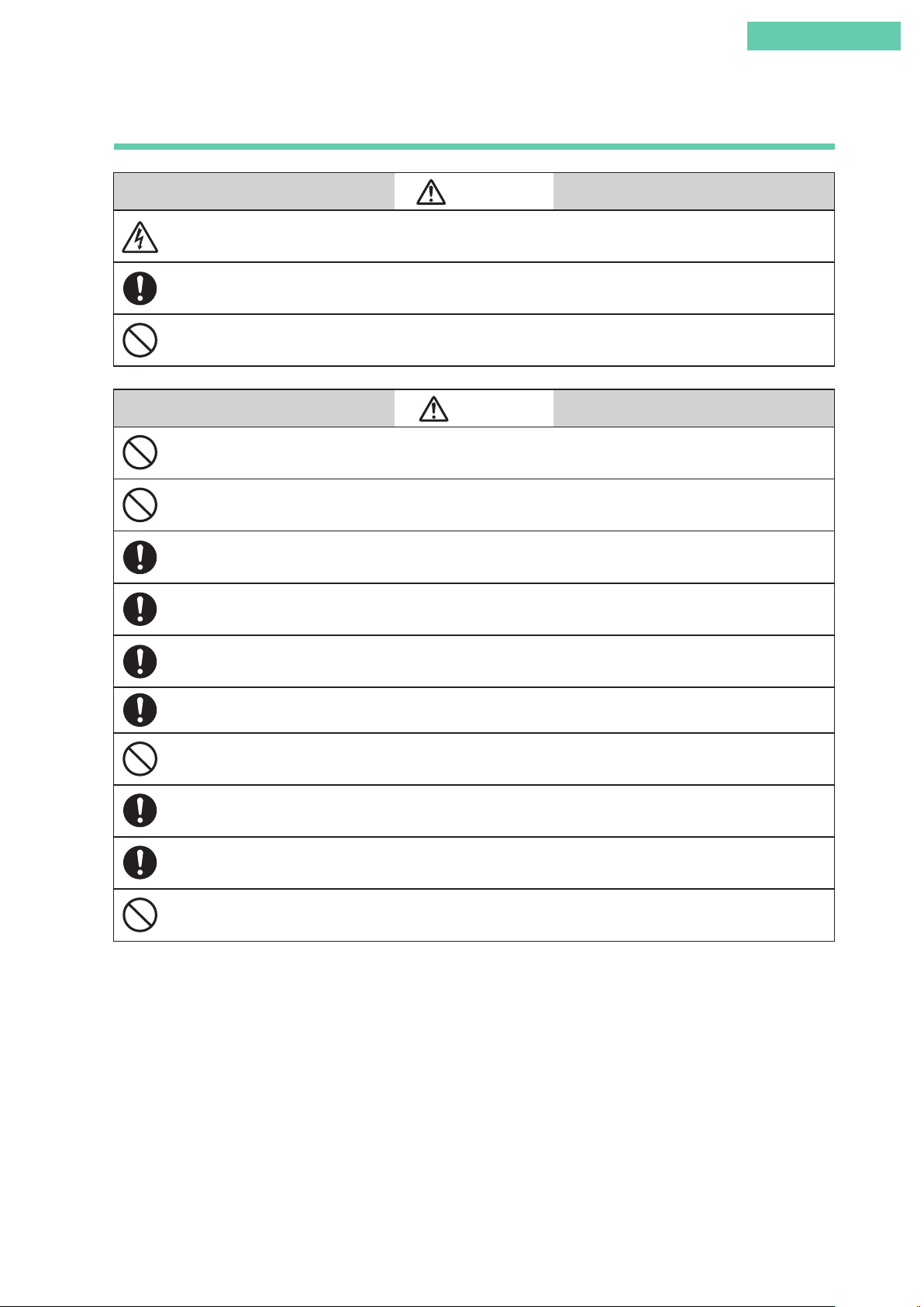
Cases in which it is conceivable that dangerous situations might arise
Warning
Caution
in which the user of the product could be seriously or fatally injured
if the product is misused.
Cases in which it is conceivable that a dangerous situation might
arise in which the user of the product could sustain minor injuries, or
physical damage could occur, if the product is misused.
■ Examples of visual indicators
This indicates a warning or caution that the user should be aware of during use.
This indicates a prohibited action.
This indicates an instruction that the user should be sure to carry out.
ii
Page 5
Cautions to ensure safe operation
Do not perform wiring work, turn on the electricity, etc., when your hands are wet. There is a risk of
electric shock. Perform this work with the power supply turned off, and with dry or gloved hands.
When wiring in a hazardous area, work according to the methods prescribed by the guidelines for the
hazardous area.
For flameproof explosion-proof specifications, do not under any circumstances open the cover during
operation (when powered up).
After installing the device, do not place your body weight on it, use it as a scaffold, etc. There is a risk that
it could fall over.
Introduction
Warning
Caution
Do not touch the device unnecessarily while it is in operation. Depending on the environment in which
the device is used, there is a danger that the surface of the device may be very hot or very cold.
When opening the cover of the terminal box, be careful of the edges of the cover, the threads of the
screws on the main unit, etc. There is a possibility of injury.
Use a DC power supply that has overload protection. An overload can cause the emission of smoke and
fire.
Bringing tools and the like into contact with the glass portion of the display can cause damage or injury.
Exercise sufficient caution. In addition, be sure to wear safety glasses.
As this product is extremely heavy, watch your footing, and be sure to wear safety shoes.
When the device is in operation, do not touch moving parts such as the feedback lever. Your hand may
become caught, resulting in injury.
Supply power correctly based on the specifications. An incorrect power input can damage the instrument.
When working in a high-temperature or low-temperature environment, wear gloves and other protective
equipment.
Do not bring magnets or magnetic screwdrivers near the device. There is a possibility that the control
valve will move in response.
iii
Page 6
Basic use
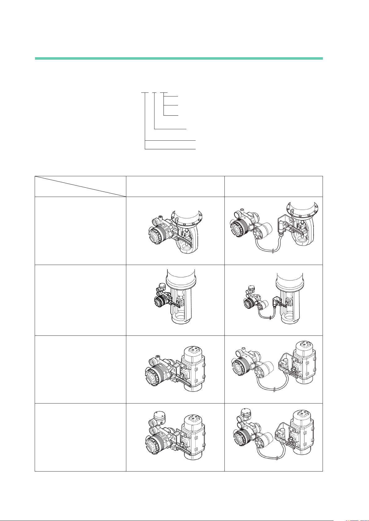
■ Basic model number structure
Model AVP 0
0: No transmission
1: With travel transmission (4 to 20mA DC or DE transmission)
2: HART
0: Fixed
■ Positioner and Actuator Types
® protocol communication
2: Remote type
3: Integral type
Positioner Type
Actuator Type
Single-acting linear diaphragm (Azbil
Corporation actuator model numbers:
PSA, HA, HK, VA, VR, RSA, GOM)
Double-acting linear cylinder (Azbil
Corporation actuator model numbers:
VP, SLOP, DAP)
Single-acting rotary cylinder
(actuator for ball valves and butterfly
valves)
Model AVP300/301/302
(Integral Type)
Model AVP200/201/202
(See p. v.) (See p. xiii.)
(See p. vii.) (See p. xvi.)
(Remote Type)
Double-acting rotary cylinder
(actuator for ball valves and butterfly
valves)
(See p. ix.) (See p. xix.)
(See p. xi.) (See p. xxi.)
iv
Page 7
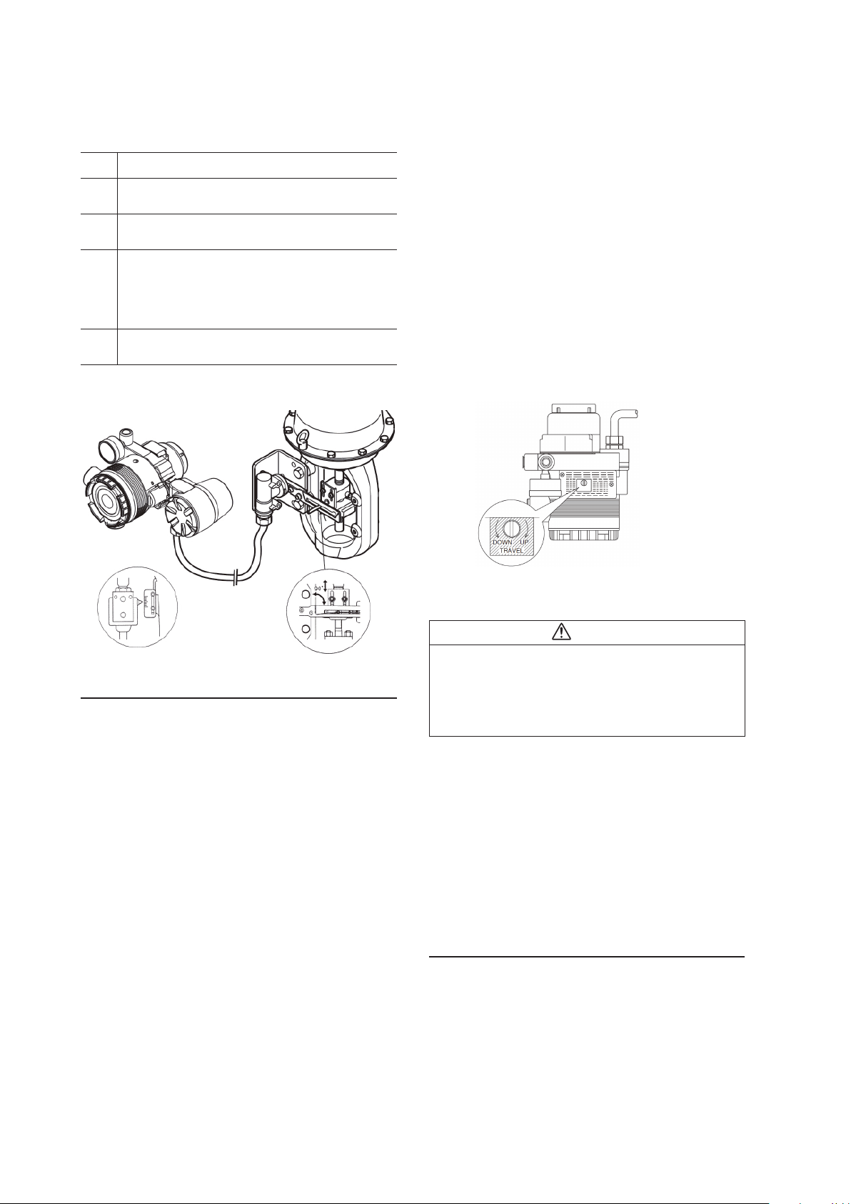
Combination of model AVP300/301/302 (integral type) and single-acting linear
diaphragm actuator
Introduction
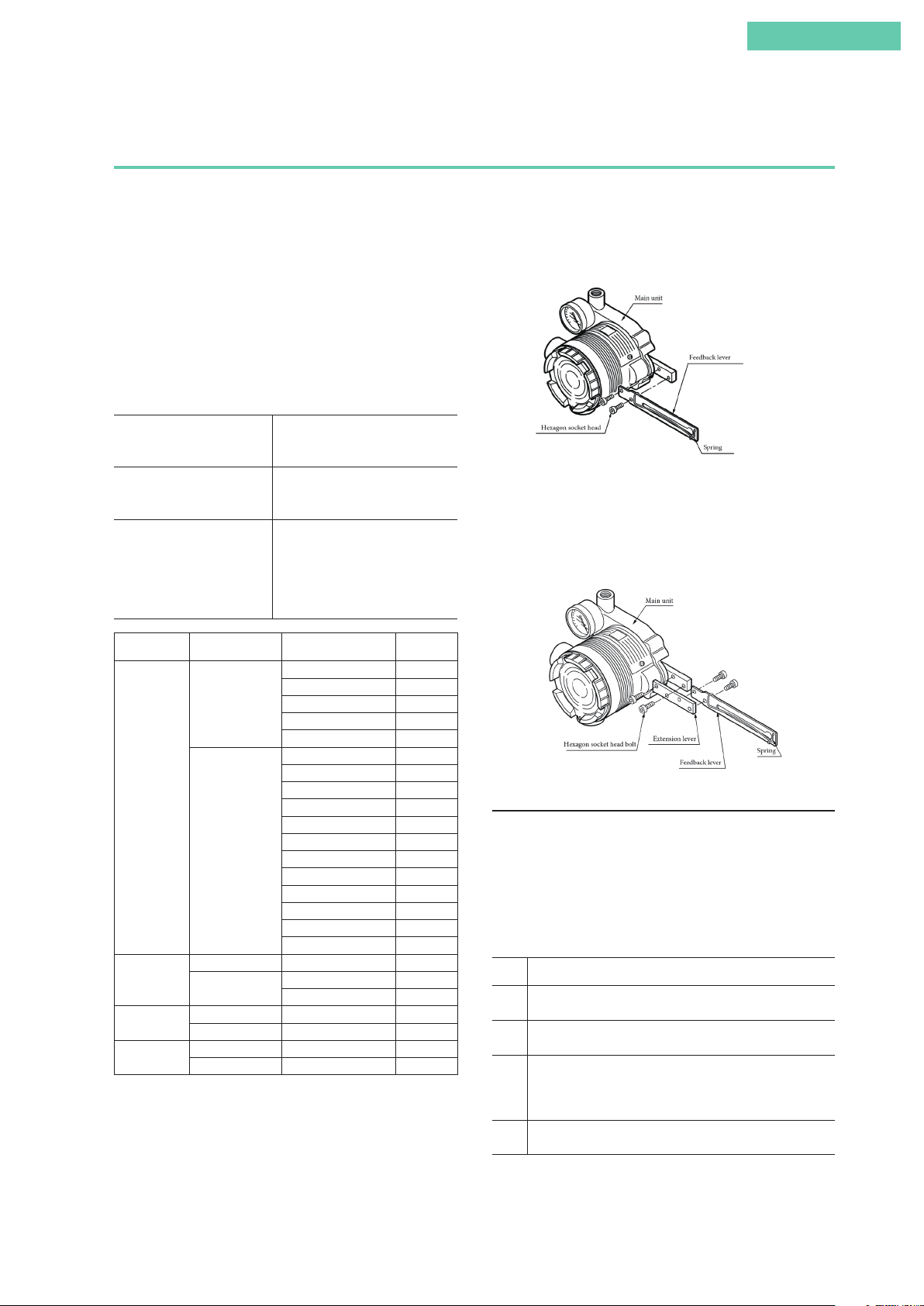
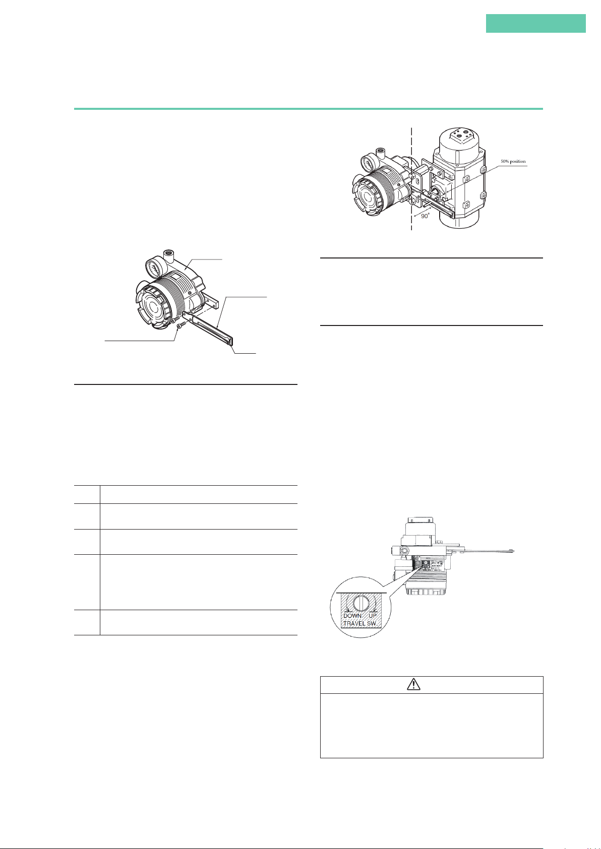
1. Attachment of feedback lever
In order to minimize the risk of damage to the feedback lever
while it is carried or transported, and to minimize the packaging as well, the feedback lever is detached from the body of
the device when it is packed. As a result, the feedback lever
must be attached to the body of the device prior to installation of the device.
The length of the feedback lever can if necessary be adjusted
by attaching the extension lever between the feedback lever
and the body of the device. Adjustment of the feedback lever
length is determined based on the form of the actuator.
If the actuator type is specified
when ordering, and the
extension lever is included:
If the actuator type is specified
when ordering, and the
extension lever is not included:
If the actuator type is not
specified when ordering:
Manufacturer Extension Lever Actuator Type Code
No
Azbil
Corporation
Ye s
No #240, #280, #330 TA, TD
Motoyama
Masoneilan
Nihon Koso
Ye s
No #11, #13 MA, MB
Ye s #15, #18 MC, MF
No #270, #320 TA, TD
Ye s #400, #500 TB, TE
When connecting an actuator other than those in the table,
connect the device and the actuator, and then switch to
manual mode and move the actuator slowly and ensure that
the feedback lever does not interfere with the full stroke of
the actuator.
Attach the extension lever to the
body of the device, and then attach
the feedback lever.
The extension lever is not necessary.
Attach the feedback lever directly to
the body of the device.
The extension lever will be
included. Refer to the table below
to determine, based on the actuator
with which the device is equipped,
whether or not the extension lever
is necessary.
PSA1, 2, PSK1 YS
HA1 YA
HA2, 3 YT
HK1 YK
VA1 to 3 YQ
PSA3, 4 YQ
PSA6 YL
HA4 YN
PSA7 Y8
VA4 to 6 YL
RSA1 YF
RSA2 YU
VR1 YV
VR2, 3 YR
VR3H Y6
GOM83S, 84S, 103S YG
GOM124S YM
#400, #500S, #500L TB, TE
#650S, #650L TC, TF
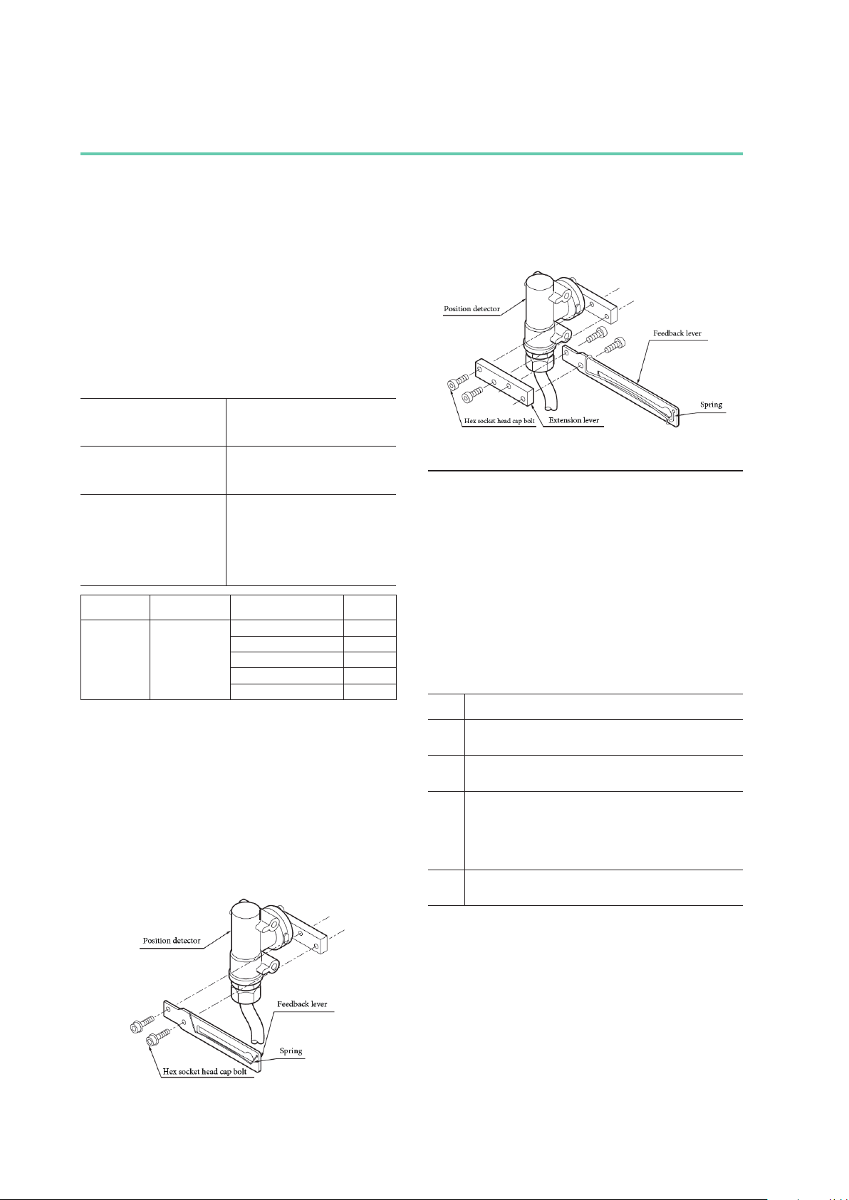
If the feedback lever alone cannot cover a full stroke, attach
the extension lever to it.
Attach the feedback lever securely, working from the front of
the device, using the two included hexagon socket head bolts.
Attachment of Feedback Lever
Attach the extension lever securely, working from the front of
the device, using the two included hexagon socket head bolts.
Then, in the same way, attach the feedback lever securely,
working from the back of the device. (The feedback lever can
be attached from the front as well.)
Attachment of Extension Lever and Feedback Lever
2. Attachment and installation
[1] Attachment to the actuator
Attach to the actuator with a mounting plate that is appropriate for the actuator.
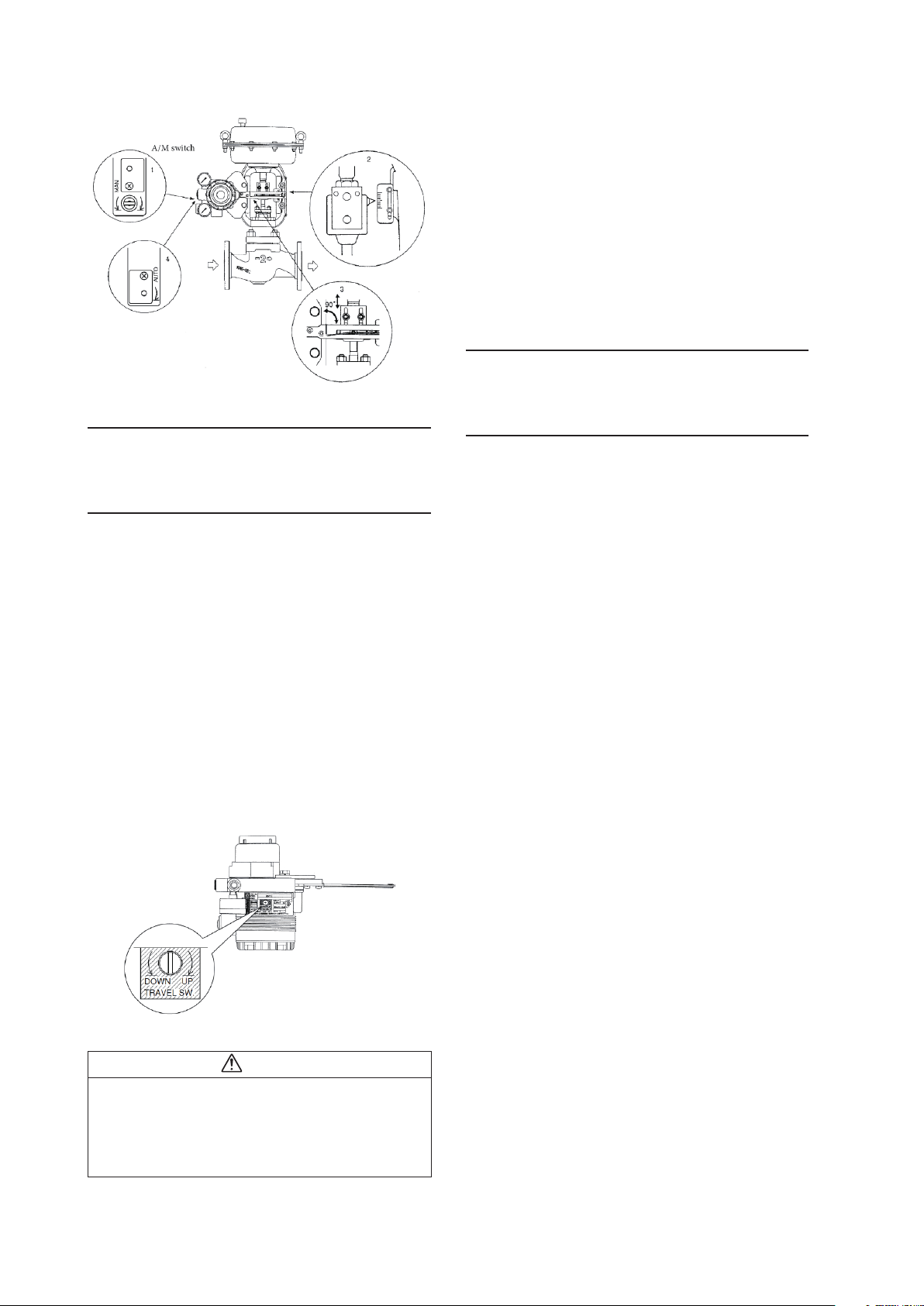
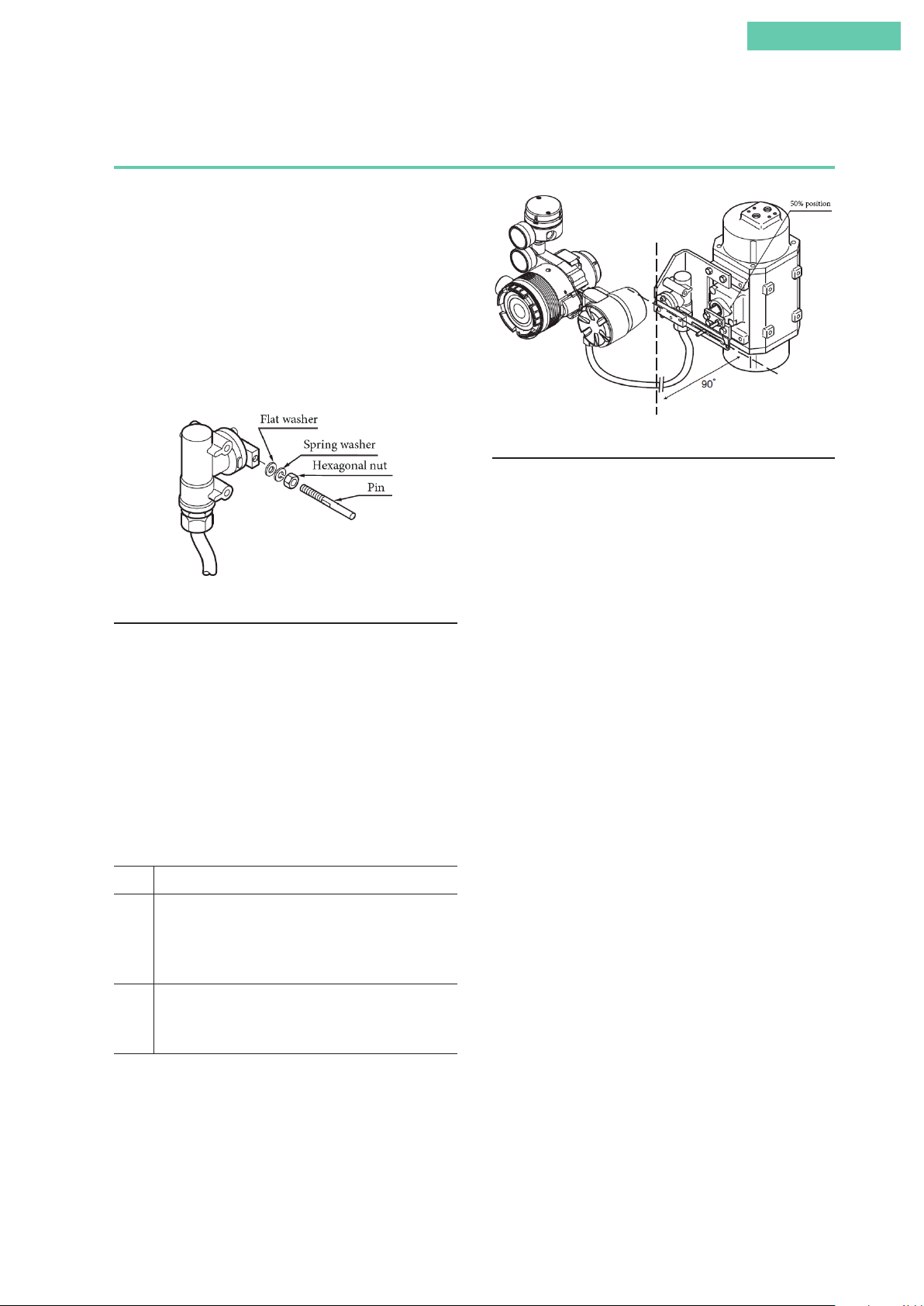
[2] Adjustment of attachment positions
Procedure for adjustment of attachment positions
Step Procedure
1 Set the A/M switch to manual operation.
(See 5.2, “A/M Switch.”)
2 Supply air, and adjust the actuator air pressure such that the
actuator stem reaches the travel midpoint.
3 Adjust the actuator such that the feedback lever reaches a
90° angle to the device's central vertical axis. Depending on
the actuator being used, adjustment may be performed by
moving the device, or it may be performed by moving a pin.
4 Set the A/M switch to automatic operation.
(See 5.2, “A/M Switch.”)
Note: The accuracy specifications can be satisfied by making
the attachment angle 90° ±2°.
v
Page 8
Adjustment of Attachment Positions
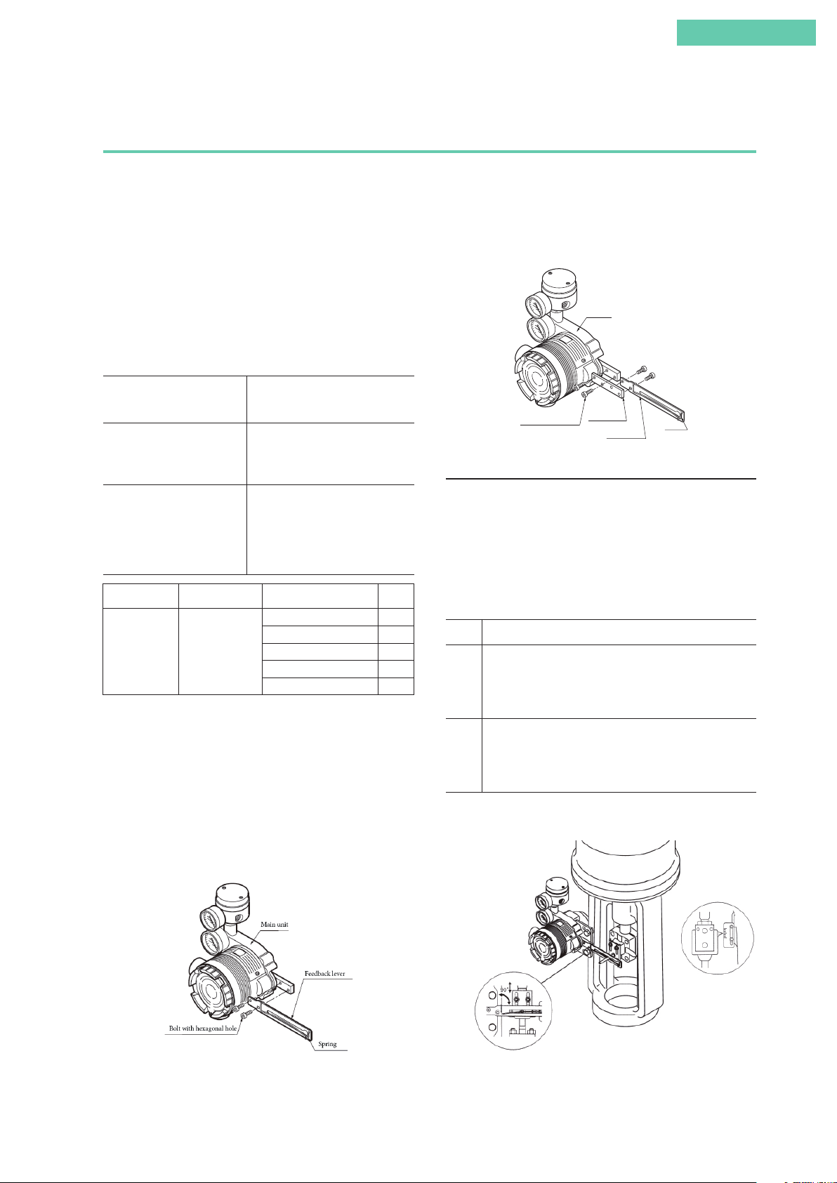
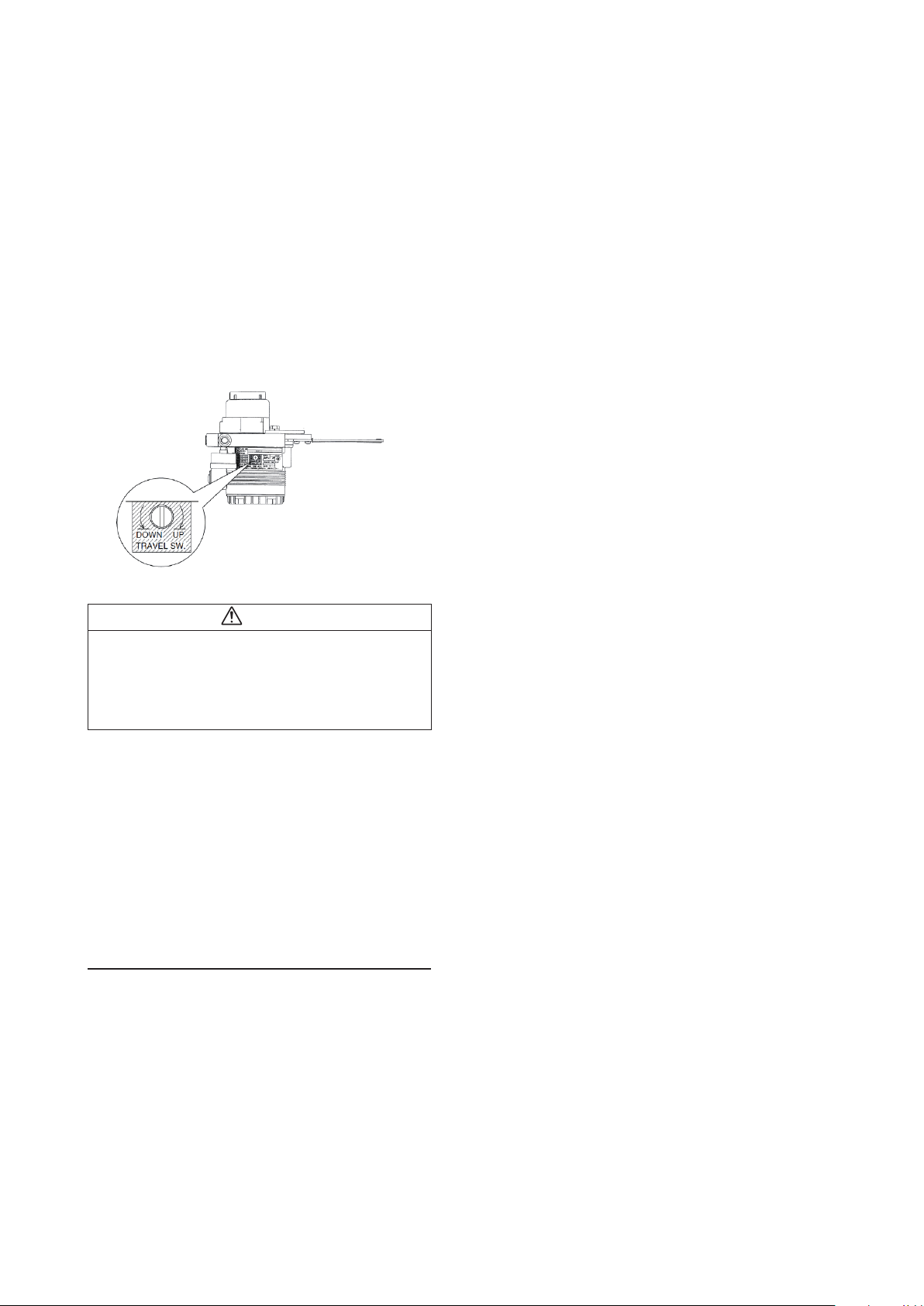
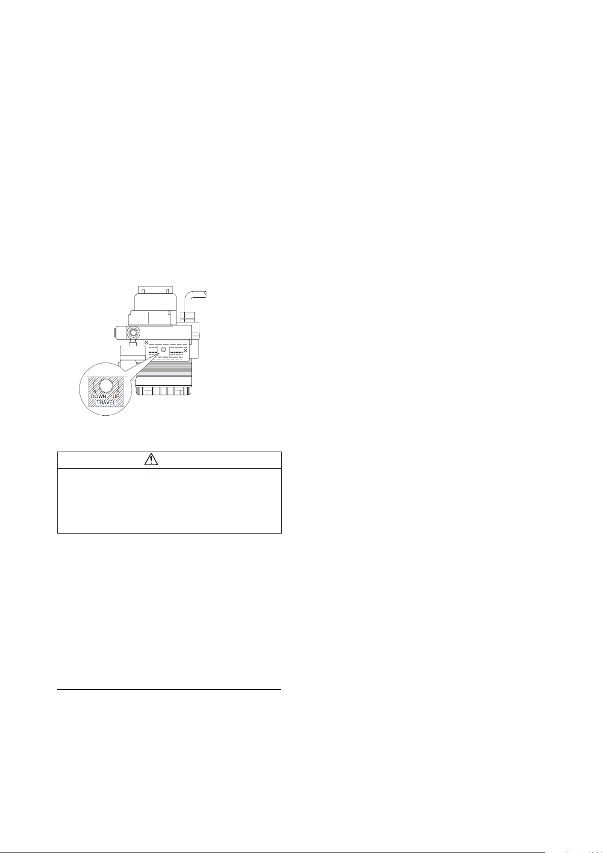
Check the span point and perform span adjustment.
(1) Set the input signal to the span point (URV). (Zero ad-
justment can be performed if the input signal is adjusted
to the zero point, and span adjustment can be performed
if the input signal is adjusted to the span point.)
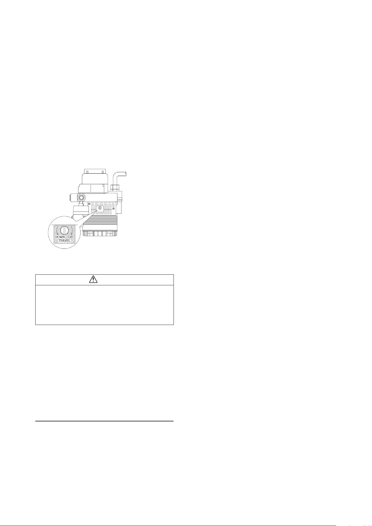
(2) Using a flat-blade screwdriver, turn the external zero
span adjustment switch on the upper part of the case UP
(clockwise) to cause the valve to move such that the feedback lever rises upward, or turn it DOWN (counterclockwise) to cause the valve to move such that the feedback
lever drops downward.
5. Operation confirmation
Vary the input signal, and check the zero point and span
point.
3. Air piping and electric wiring connection
Connect the air piping and electrical wiring.
For details, see 2.2, “Installation Method,” in this document.
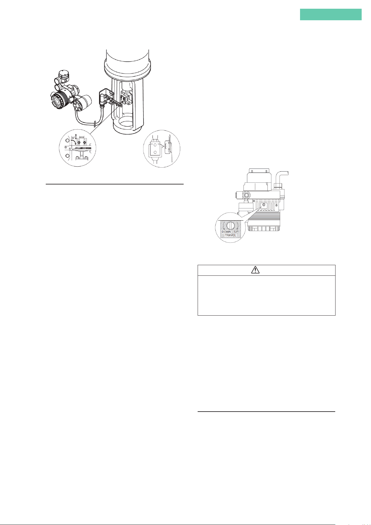
4. Auto-setup
(1) Set the input signal to 18 ±1mA.
(2) Using a flat-blade screwdriver, turn the external zero/
span adjustment switch in the upper part of the case 90°
in the UP direction (the DOWN direction for Azbil Corporation's VR and RSA actuators for VFR type control
valves), and hold that position for three seconds.
Note: For reverse close (when the valve's fully closed position is on top), set the valve action to reverse close beforehand. See 4.4.3, “Valve system”
(3) The valve will automatically start to move, and will stop
in about 3 to 4 minutes.
(4) When it stops, adjust it to a position that fits the input
signal.
(5) After that, check whether it has been adjusted correctly.
If performing auto-setup
DOWN direction:
VFR type
UP direction: direct type
External zero/span adjustment switch
Note: When closing the
valve of the single-acting
type device with the lever
in the upward direction,
first set it to reverse close.
• Auto-setup can be performed with CommStaff as well.
Warning
When auto-setup is performed, the valve moves from fully
closed to fully open, so there is a danger of, for example,
getting your hand caught or affecting the process.
Before performing auto-setup, move away from the valve,
and confirm that the process is safe.
6. If suitable adjustment was not accomplished
[1] If auto-setup does not operate
• Check whether the input signal is 18 mA ± 1 mA.
• Check whether the A/M switch is set to automatic. If it is
set to manual, switch it to auto. See 5.2, “A/M Switch,” in
this document for information on operating procedures.
• Check the duty value of the electro-pneumatic module.
Regarding the confirmation method, see “EPM (electropneumatic module) operation confirmation procedure” on
page 3-9 in this document.
• Check whether the electronics module (terminal block) is
installed correctly in the case on the body of the device.
[2] If hunting occurs
• Using the setup device, either change the actuator size
(Param) or individually set the valve position control PID.
Regarding the configuration method, see 4.4.4, “Control
configuration,” below.
[3] If the zero point floats or span adjustment cannot be
performed
Referring to Table 3-1, “Integral type setting,” in 3.1, “Autosetup,” in this document, check whether valve action is
configured correctly. If not, it will be necessary to change the
valve action (the direct/reverse setting). Referring to 4.4.3,
“Valve system,” in this document, configure the valve action
correctly.
[4] If linearity characteristic is poor
• Check whether, when the attachment position of the feed-
back lever is the 50% opening position, it is attached horizontally. If not, refer to 2.2, “Installation Method,” in this
document and correctly attach the feedback lever.
• Check the flow rate characteristics data. If equal%, quick
open, or the like has been specified, and these are fundamentally unnecessary, refer to 4.4.6, “Flow Type,” in this
document and change this setting to linear.
vi
Page 9
Introduction
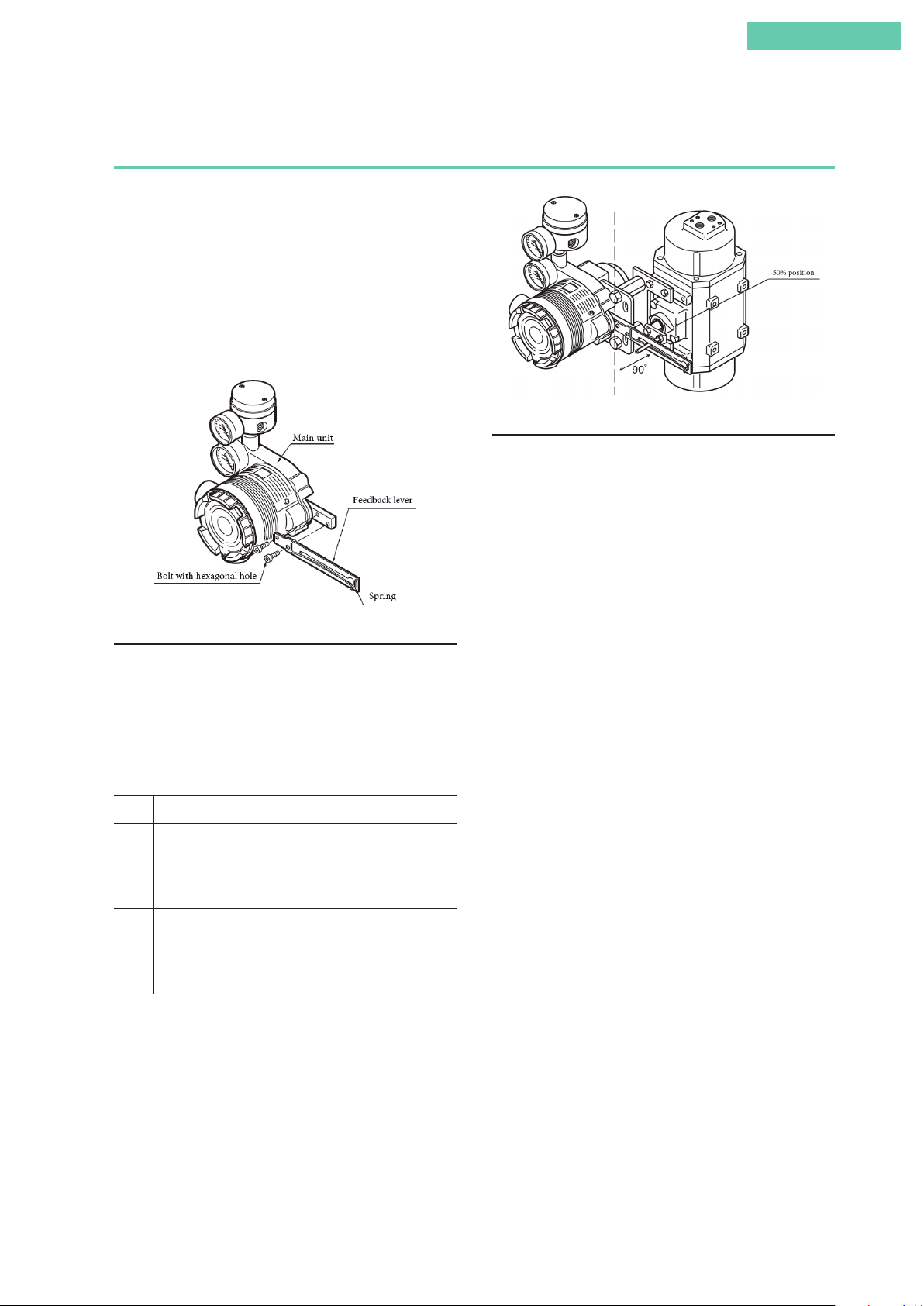
Combination of model AVP300/301/302 (integral type) and double-acting linear cylinder
actuator
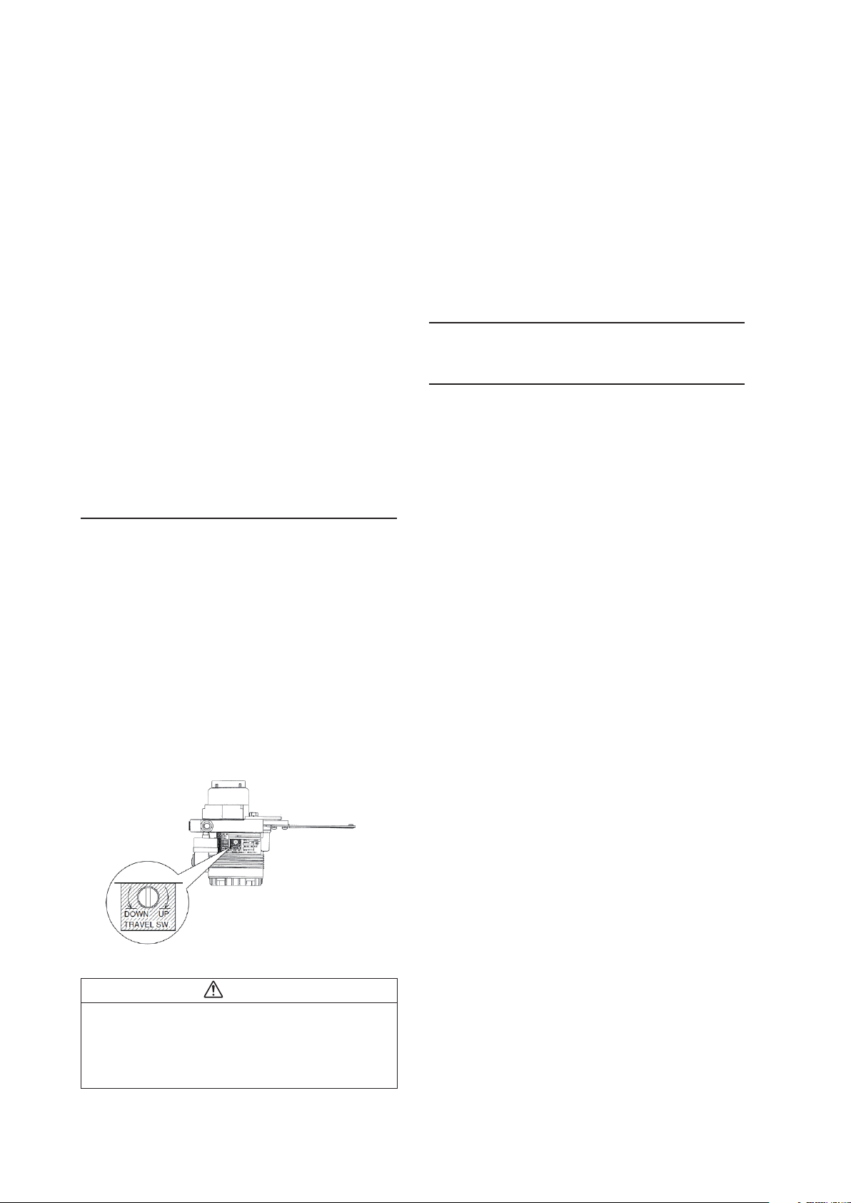
1. Attachment of feedback lever
In order to minimize the risk of damage to the feedback lever
while it is carried or transported, and to minimize the packaging as well, the feedback lever is detached from the body of
the device when it is packed. As a result, the feedback lever
must be attached to the body of the device prior to installation of the device.
The length of the feedback lever can if necessary be adjusted
by attaching the extension lever between the feedback lever
and the body of the device. Adjustment of the feedback lever
length is determined based on the form of the actuator.
If the actuator type is specified when ordering, and the
extension lever is included:
If the actuator type is specified when ordering, and the
extension lever is not included:
If the actuator type is not
specified when ordering:
Manufacturer Extension Lever Actuator Type Code
Azbil
Corporation
(SLOP type and DAP type are limited to products with stroke of
100 mm or less)
When connecting an actuator other than those in the table,
connect the device and the actuator, and then, via manual
operation, move the actuator slowly and ensure that the feedback lever does not interfere with a full stroke of the actuator.
If the feedback lever alone cannot cover a full stroke, attach
the extension lever to it.
Attach the feedback lever securely, working from the front of
the device, using the two included hexagon socket head bolts.
Attach the extension lever to the
body of the device, and then attach
the feedback lever.
The extension lever is not necessary. Attach the feedback lever
directly to the body of the device.
The extension lever will be included. Refer to the table below to
determine, based on the actuator
with which the device is equipped,
whether or not the extension lever
is necessary.
VP5, 6, 7 Y1
SLOP560, 1000, 1000X Y2
Yes
SLOP1500, 1500X Y3
DAP560, 1000, 1000X Y4
DAP1500, 1500X Y5
Attach the extension lever securely, working from the front of
the device, using the two included hexagon socket head bolts.
Then, in the same way, attach the feedback lever securely,
working from the back of the device. (The feedback lever can
be attached from the front as well.)
Main unit
Bolt with hexagonal hole
Attachment of Extension Lever and Feedback Lever
Extension lever
Feedback lever
Spring
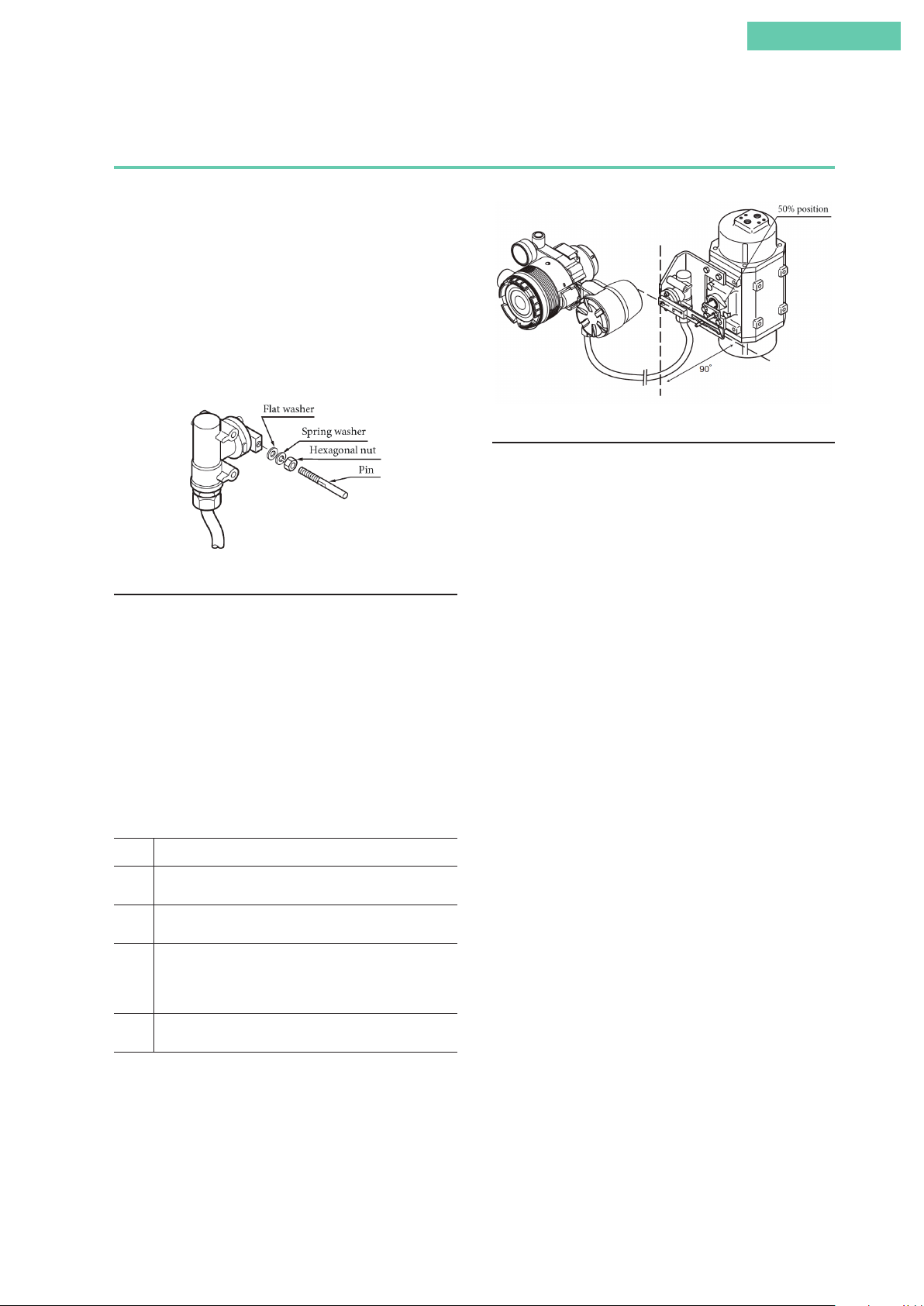
2. Attachment and installation
[1] Attachment to the actuator
Attach to the actuator with a mounting plate that is appropriate for the actuator.
[2] Adjustment of attachment positions
Procedure for adjustment of attachment positions
Step Procedure
1 Using for example the manual handle of the actuator
or manual operation via the external pressure regulator
with filter, set the position to 50%. (With a double-acting
actuator, manual operation cannot be performed using the
A/M switch.)
2 Adjust the actuator such that the feedback lever reaches a
90° angle to the device's central vertical axis. Depending on
the actuator being used, adjustment may be performed by
moving the device, or it may be performed by moving the
pin.
Note: The accuracy specifications can be satisfied by making
the attachment angle 90° ±2°.
Attachment of Feedback Lever
Adjustment of Attachment Positions
vii
Page 10
3. Air piping and electric wiring connection
• Air piping connection
(1) If control operation of control valve is direct operation
This refers to the state in which the valve moves in the
closing direction as the input signal increases. Connect
the reversing relay output OUT1 to the cylinder chamber
that performs output in order to close the valve in response to increased pressure.
Next, connect the reversing relay output OUT2 to the
cylinder chamber that performs output in order to open
the valve in response to increased pressure.
(2) If control operation of control valve is reverse operation
This refers to the state in which the valve moves in the
opening direction as the input signal increases. Connect
the reversing relay output OUT2 to the cylinder chamber
that performs output in order to close the valve in response to increased pressure.
Next, connect the reversing relay output OUT1 to the
cylinder chamber that performs output in order to open
the valve in response to increased pressure.
For details, see air piping connection and electric wiring
connection in 1.3, “Description of Device Structure and
Functions,” and 2.2, “Installation Method,” in this document.
Check the span point and perform span adjustment.
(1) Set the input signal to the span point (URV). (Zero ad-
justment can be performed if the input signal is adjusted
to the zero point, and span adjustment can be performed
if the input signal is adjusted to the span point.)
(2) Using a flat-blade screwdriver, turn the external zero
span adjustment switch on the upper part of the case UP
(clockwise) to cause the valve to move such that the feedback lever rises upward, or turn it DOWN (counterclockwise) to cause the valve to move such that the feedback
lever drops downward.
5. Operation confirmation
Vary the input signal, and check the zero point and span point.
6. If suitable adjustment was not accomplished
[1] If auto-setup does not operate
• Check whether the input signal is 18 mA ±1 mA.
• Check whether the A/M switch is set to automatic. If it is
set to manual, switch it to auto. See 5.2, “A/M Switch,” in
this document for information on operating procedures.
4. Auto-setup
(1) Set the input signal to 18 ±1 mA.
(2) Using a flat-blade screwdriver, turn the external zero/
span adjustment switch in the upper part of the case 90°
in the UP direction (clockwise), and hold that position
for three seconds.
Note: For reverse close (when the valve's fully closed position is on top), set the valve action to reverse close beforehand. See 4.4.3, “Valve system”)
(3) The valve will automatically start to move, and will stop
in about 3 to 4 minutes.
(4) When it stops, move it to a position that fits the input
signal.
(5) After that, check whether it has been adjusted correctly.
If performing auto-setup
Rotate in UP direction
External zero/span adjustment switch
Note: When closing the
valve of the single-acting
type device with the lever
in the upward direction,
first set it to reverse close.
• Auto-setup can be performed with CommStaff as well.
Warning
When auto-setup is performed, the valve moves from fully
closed to fully open, so there is a danger of, for example,
getting your hand caught or affecting the process.
Before performing auto-setup, move away from the valve,
and confirm that the process is safe.
• Check the duty value of the electro-pneumatic module.
Regarding the confirmation method, see “EPM (electropneumatic module) operation confirmation procedure” on
page 3-9 in this document.
• Check whether the electronics module (terminal block) is
installed correctly in the case on the body of the device.
[2] If hunting occurs
•
Using the setup device, either change the actuator size
(Param) or change the individual PID settings that control
the AVP’s degree of opening. Regarding the configuration
method, see 4.4.4, “Control configuration,” in this document.
[3] If the zero point floats or span adjustment cannot be
performed
Referring to Table 3-1, “Integral type setting,” in 3.1, “Autosetup,” in this document, check whether valve action is
configured correctly. If not, it will be necessary to change the
valve action (the direct/reverse setting). Referring to 4.4.3,
“Valve system” in this document, configure the valve action
correctly.
[4] If linearity characteristic is poor
• Check whether, when the attachment position of the feed-
back lever is the 50% opening position, it is attached horizontally. If not, refer to 2.2, “Installation Method,” in this
document and correctly attach the feedback lever.
• Check the flow rate characteristics data. If equal%, quick
open, or the like has been specified, and these are fundamentally unnecessary, refer to 4.4.6, “Flow Type,” in this
document and change this setting to linear.
viii
Page 11
Introduction
Combination of model AVP300/301/302 (integral type) and single-acting rotary cylinder
actuator
1. Attachment of feedback lever
In order to minimize the risk of damage to the feedback lever
while it is carried or transported, and to minimize the packaging as well, the feedback lever is detached from the body of
the device when it is packed. As a result, the feedback lever
must be attached to the body of the device prior to installation of the device.
Attach the feedback lever securely, working from the front of
the device, using the two included hexagon socket head bolts.
Main unit
Feedback lever
3. Air piping and electric wiring connection
Connect the air piping and electrical wiring.
For details, see section 2.2, “Installation Method,” in this
document.
Adjustment of Attachment Positions
Bolt with hexagonal hole
Spring
Attachment of Feedback Lever
2. Attachment and installation
[1] Attachment to the actuator
Attach to the actuator with a mounting plate that is appropriate for the actuator.
[2] Adjustment of attachment positions
Procedure for adjustment of attachment positions
Step Procedure
1 Set the A/M switch to manual operation.
(See 5.2, “A/M Switch.”)
2 Supply air, and adjust the actuator air pressure such that the
actuator stem reaches the travel midpoint.
3 Adjust the actuator such that the feedback lever reaches a
90° angle to the device's central vertical axis. Depending
on the actuator being used, adjustment may be performed
by moving the device, or it may be performed by moving
the pin.
4 Set the A/M switch to automatic operation.
(See 5.2, “A/M Switch.”)
Note: The accuracy specifications can be satisfied by making
the attachment angle 90° ± 2°.
4. Auto-setup
(1) Set the input signal to 18 ± 1 mA.
(2) Using a flat-blade screwdriver, turn the external zero/
span adjustment switch in the upper part of the case 90°
in the UP direction (clockwise), and hold that position
for three seconds.
Note: For reverse close (when the valve's fully closed position is on top), set the valve action to reverse close beforehand. See 4.4.4, “Control configuration,” in this document.
(3) The valve will automatically start to move, and will stop
in about 3 to 4 minutes.
(4) When it stops, adjust it to a position that fits the input
signal.
(5) After that, check whether it has been adjusted correctly.
If performing auto-setup
Rotate in UP direction
External zero/span adjustment switch
• Auto-setup can be performed with CommStaff as well.
Note: When closing the valve
of the single-acting type device
with the lever in the upward
direction, first set it to reverse
close.
Warning
When auto-setup is performed, the valve moves from fully
closed to fully open, so there is a danger of, for example,
getting your hand caught or affecting the process.
Before performing auto-setup, move away from the valve,
and confirm that the process is safe.
ix
Page 12

Check the span point and perform span adjustment.
(1) Set the input signal to the span point (URV). (Zero ad-
justment can be performed if the input signal is adjusted
to the zero point, and span adjustment can be performed
if the input signal is adjusted to the span point.)
(2) Using a flat-blade screwdriver, turn the external zero
span adjustment switch on the upper part of the case in
the UP direction (clockwise) to cause the valve to move
such that the feedback lever rises upward, or turn it
DOWN (counterclockwise) to cause the valve to move
such that the feedback lever drops downward.
5. Operation confirmation
Vary the input signal, and check the zero point and span
point.
6. If suitable adjustment was not accomplished
[1] If auto-setup does not operate
• Check whether the input signal is 18 mA ±1 mA.
• Check whether the A/M switch is set to automatic. If it is
set to manual, switch it to auto. See 5.2, “A/M Switch,” in
this document for information on operating procedures.
• Check the duty value of the electro-pneumatic module.
Regarding the confirmation method, see “EPM (electropneumatic module) operation confirmation procedure” on
page 3-9 in this document.
• Check whether the electronics module (terminal block) is
installed correctly in the case on the body of the device.
[2] If hunting occurs
Using the setup device, either change the actuator size
(Param) or change the individual PID settings that control
the AVP’s degree of opening. Regarding the configuration
method, see 4.4.4, “Control configuration,” in this document.
[3] If the zero point floats or span adjustment cannot be
performed
Referring to Table 3-1, “Integral type setting,” in 3.1, “Autosetup,” in this document, check whether valve action is
configured correctly. If not, it will be necessary to change the
valve action (the direct/reverse setting). Referring to 4.4.3,
“Valve system,” in this document, configure the valve action
correctly.
[4] If linearity characteristic is poor
• Check whether, when the attachment position of the feed-
back lever is the 50% opening position, it is attached horizontally. If not, refer to 2.2, “Installation Method,” in this
document and correctly attach the feedback lever.
• Check the flow rate characteristics data. If equal%, quick
open, or the like has been specified, and these are fundamentally unnecessary, refer to 4.4.6, “Flow Type,” in this
document and change this setting to linear.
x
Page 13
Introduction
Combination of model AVP300/301/302 (integral type) and double-acting rotary cylinder
actuator
1. Attachment of feedback lever
In order to minimize the risk of damage to the feedback lever
while it is carried or transported, and to minimize the packaging as well, the feedback lever is detached from the body of
the device when it is packed. As a result, the feedback lever
must be attached to the body of the device prior to installation of the device.
Attach the feedback lever securely, working from the front of
the device using the two included hexagon socket head bolts.
Adjustment of Attachment Positions
3. Air piping and electric wiring connection
• Air piping connection
(1) If control operation of control valve is direct operation
This refers to the state in which the valve moves in the
closing direction as the input signal increases. Connect
the reversing relay output OUT1 to the cylinder chamber
that performs output in order to close the valve in response to increased pressure.
Attachment of Feedback Lever
2. Attachment and installation
[1] Attachment to the actuator
Attach to the actuator with a mounting plate that is appropriate for the actuator.
[2] Adjustment of attachment positions
Procedure for adjustment of attachment positions
Step Procedure
1 Using for example the manual handle of the actuator
or manual operation via the external pressure regulator
with filter, set the position to 50%. (With a double-acting
actuator, manual operation cannot be performed using the
A/M switch.)
2 Adjust the actuator such that the feedback lever reaches a
90° angle to the device's central vertical axis. Depending on
the actuator being used, adjustment may be performed by
moving the device, or it may be performed by moving the
pin.
Next, connect the reversing relay output OUT2 to the
cylinder chamber that performs output in order to open
the valve in response to increased pressure.
(2) If control operation of control valve is reverse operation
This refers to the state in which the valve moves in the
opening direction as the input signal increases. Connect
the reversing relay output OUT2 to the cylinder chamber
that performs output in order to close the valve in response to increased pressure.
Next, connect the reversing relay output OUT1 to the
cylinder chamber that performs output in order to open
the valve in response to increased pressure.
For details, see air piping connection and electric wiring
connection in 1.3, “Description of Device Structure and
Functions,” and 2.2, “Installation Method,” in this document.
Note: The accuracy specifications can be satisfied by making
the attachment angle 90° ± 2°.
xi
Page 14
4. Auto-setup
(1) Set the input signal to 18 ± 1 mA.
Using a flat-blade screwdriver, turn the external zero/span
(2)
adjustment switch in the upper part of the case 90° in the
UP direction, and hold that position for three seconds.
Note: For reverse close (when the valve's fully closed position is on top), set the valve action to reverse close beforehand. See 4.4.3, “Valve system”
(3) The valve will automatically start to move, and will stop
in about 3 to 4 minutes.
(4) When it stops, adjust it to a position that fits the input
signal.
(5) After that, check whether it has been adjusted correctly.
If performing auto-setup
Rotate in UP direction
External zero/span adjustment switch
Note: When closing the valve
of the single-acting type device
with the lever in the upward
direction, first set it to reverse
close.
• Auto-setup can be performed with CommStaff as well.
Warning
When auto-setup is performed, the valve moves from fully
closed to fully open, so there is a danger of, for example,
getting your hand caught or affecting the process.
Before performing auto-setup, move away from the valve,
and confirm that the process is safe.
Check the span point and perform span adjustment.
(1) Set the input signal to the span point (URV). (Zero ad-
justment can be performed if the input signal is adjusted
to the zero point, and span adjustment can be performed
if the input signal is adjusted to the span point.)
(2) Using a flat-blade screwdriver, turn the external zero
span adjustment switch on the upper part of the case UP
(clockwise) to cause the valve to move such that the feedback lever rises upward, or turn it DOWN (counterclockwise) to cause the valve to move such that the feedback
lever drops downward.
6. If suitable adjustment was not accomplished
[1] If auto-setup does not operate
• Check whether the input signal is 18 mA ± 1 mA.
• Check whether the A/M switch is set to automatic. If it is
set to manual, switch it to auto. See 5.2, “A/M Switch,” in
this document for information on operating procedures.
• Check the duty value of the electro-pneumatic module.
Regarding the confirmation method, see “EPM (electropneumatic module) operation confirmation procedure” on
page 3-9 in this document.
• Check whether the electronics module (terminal block) is
installed correctly in the case on the body of the device.
[2] If hunting occurs
• Using the setup device, either change the actuator size
(Param) or change the individual PID settings that control
the AVP’s degree of opening. Regarding the configuration
method, see 4.4.4, “Control configuration,” in this document.
[3] If the zero point floats or span adjustment cannot be
performed
Referring to Table 3-1, “Integral type setting,” in 3.1, “Autosetup,” in this document, check whether valve action is configured correctly. If not, it will be necessary to change valve
action (the direct/reverse setting). Referring to 4.4.3, “Valve
system,” in this document, configure valve action correctly.
[4] If linearity characteristic is poor
• Check whether, when the attachment position of the feed-
back lever is the 50% opening position, it is attached horizontally. If not, refer to 2.2, “Installation Method,” in this
document and correctly attach the feedback lever.
• Check the flow rate characteristics data. If equal%, quick
open, or the like has been specified, and these are fundamentally unnecessary, refer to 4.4.6, “Flow Type,” in this
document and change this setting to linear.
5. Operation confirmation
Vary the input signal, and check the zero point and span
point.
xii
Page 15
Introduction
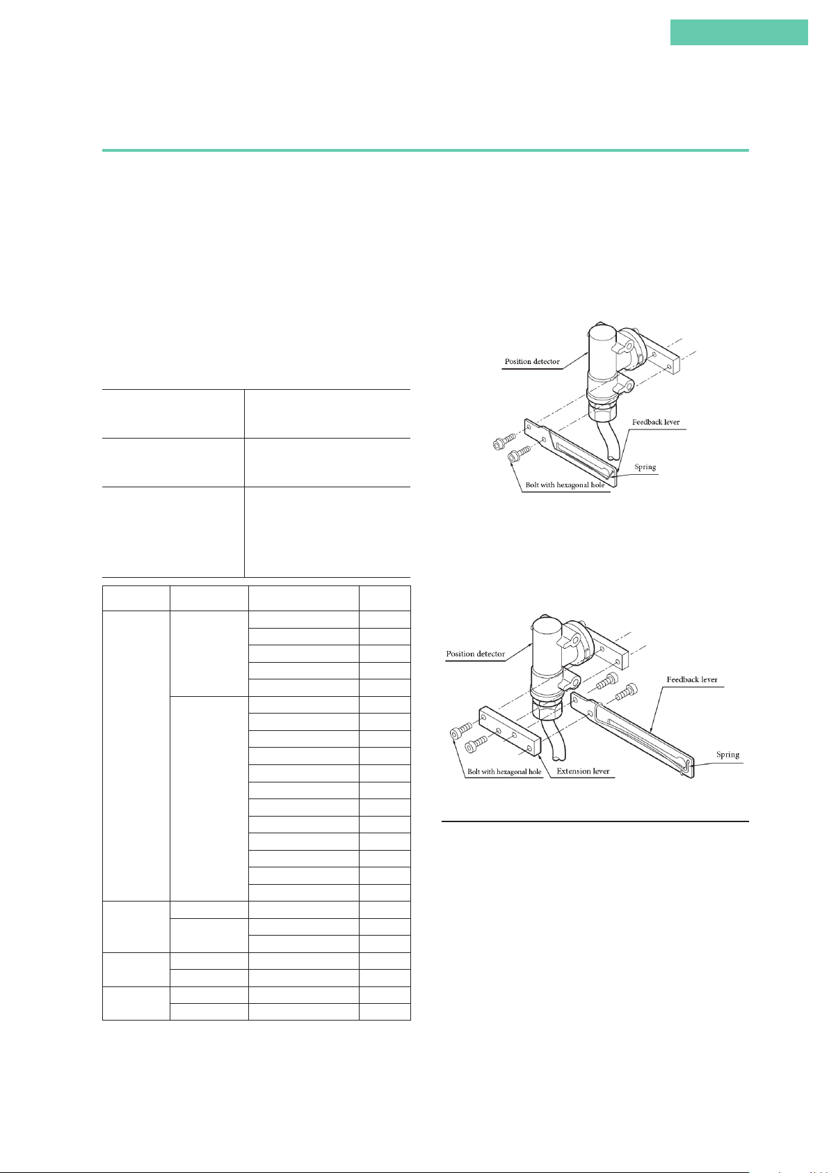
Combination of model AVP200/201/202 (remote type) and single-acting linear diaphragm
actuator
1. Attachment of feedback lever
In order to minimize the risk of damage to the feedback lever
while it is carried or transported, and to minimize the packaging as well, the feedback lever is detached from the valve
travel detector when it is packed. As a result, the feedback
lever must be attached to the valve travel detector prior to
installation of the device.
The length of the feedback lever can if necessary be adjusted
by attaching the extension lever between the feedback lever
and the valve travel detector.
Adjustment of the feedback lever length is determined based
on the form of the actuator.
If the actuator type is specified
when ordering, and the
extension lever is included:
If the actuator type is specified
when ordering, and the
extension lever is not included:
If the actuator type is not
specified when ordering:
Manufacturer Extension Lever Actuator Type Code
No
Azbil
Corporation
Ye s
No #240, #280, #330 TA, TD
Motoyama
Masoneilan
Nihon Koso
Ye s
No #11, #13 MA, MB
Ye s #15, #18 MC, MF
No #270, #320 TA, TD
Ye s #400, #500 TB, TE
Attach the extension lever to the
body of the device, and then attach
the feedback lever.
The extension lever is not necessary.
Attach the feedback lever directly to
the body of the device.
The extension lever will be
included. Refer to the table below
to determine, based on the actuator
with which the device is equipped,
whether or not the extension lever
is necessary.
PSA1, 2, PSK1 YS
HA1 YA
HA2, 3 YT
HK1 YK
VA1 to 3 YQ
PSA3, 4 YQ
PSA6 YL
HA4 YN
PSA7 Y8
VA4 to 6 YL
RSA1 YF
RSA2 YU
VR1 YV
VR2, 3 YR
VR3H Y6
GOM83S, 84S, 103S YG
GOM124S YM
#400, #500S, #500L TB, TE
#650S, #650L TC, TF
When connecting an actuator other than those in the table,
connect the device and the actuator, and then, via manual
operation, move the actuator slowly and ensure that the feedback lever does not interfere with a full stroke of the actuator.
If the feedback lever alone cannot cover a full stroke, attach
the extension lever to it.
Attach the feedback lever securely, working from the front of
the device, using the two included hexagon socket head bolts.
Attachment of Feedback Lever
Attach the extension lever securely, working from the front of
the device, using the two included hexagon socket head bolts.
Then, in the same way, attach the feedback lever securely,
working from the back of the device. (The feedback lever can
be attached from the front as well.)
Attachment of Extension Lever and Feedback Lever
2. Attachment and installation
[1] Attachment to the actuator of the valve travel detector
When attaching the valve travel detector to the actuator,
install the cable outlet such that it does not face upward. If it
faces upward, change the direction of the feedback lever. For
details, see 2.3, “Remote Type Handling.”
[2] Positioner body configuration
Install the body of the positioner onto the 2B stanchion.
xiii
Page 16
[3] Adjustment of attachment positions
Procedure for adjustment of attachment positions
Step Procedure
1 Set the A/M switch to manual operation.
(See 5.2, “A/M Switch.”)
2 Supply air, and adjust the actuator air pressure such that the
actuator stem reaches the travel midpoint.
3 Adjust the actuator such that the feedback lever reaches a
90° angle to the valve travel detector's central vertical axis.
Depending on the actuator being used, adjustment may be
performed by moving the valve travel detector, or it may be
performed by moving the pin.
4 Set the A/M switch to automatic operation.
(See 5.2, “A/M Switch.”)
Note: The accuracy specifications can be satisfied by making
the attachment angle 90° ± 2°.
4. Auto-setup
(1) Set the input signal to 18 ±1 mA.
(2) Using a flat-blade screwdriver, turn the external zero/
span adjustment switch in the upper part of the case 90°
in the UP (clockwise) direction (the DOWN direction for
Azbil Corporation's VR and RSA actuators for VFR type
control valves), and hold that position for three seconds.
Note: For reverse close (when the valve's fully closed position is on top), set the valve action to reverse close beforehand. See 4.4.3, “Valve system”
(3) The valve will automatically start to move, and will stop
in about 3 to 4 minutes.
(4) When it stops, adjust it to a position that fits the input
signal.
(5) After that, check whether it has been adjusted correctly.
If performing auto-setup
DOWN direction:
VFR type
UP direction:
direct type
External zero/span adjustment switch
Note: When closing the
valve of the single-acting
type device with the lever
in the upward direction,
first set it to reverse close.
Adjustment of Attachment Positions
3. Air piping and electric wiring connection
[1] Air piping connection
For details, see air piping connection in 2.2, “Installation
Method,” in this document.
[2] Electrical wiring connection (cables between valve
travel detector and positioner)
When shipped from the factory, the valve travel detector and
the positioner body are normally shipped separated at the
connector unit on the positioner body.
Referring to 2.3, “Remote Type Handling,” in this document,
connect the valve travel detector cable to the body of the
device using the remote cable. When laying cable, follow appropriate electrical work guidelines.
• Auto-setup can be performed with CommStaff as well.
Warning
When auto-setup is performed, the valve moves from fully
closed to fully open, so there is a danger of, for example,
getting your hand caught or affecting the process.
Before performing auto-setup, move away from the valve,
and confirm that the process is safe.
Check the span point and perform span adjustment.
(1) Set the input signal to the span point (URV). (Zero ad-
justment can be performed if the input signal is adjusted
to the zero point, and span adjustment can be performed
if the input signal is adjusted to the span point.)
(2) Using a flat-blade screwdriver, turn the external zero
span adjustment switch on the upper part of the case in
the UP direction (clockwise) to cause the valve to move
such that the feedback lever rises upward, or turn it
DOWN (counterclockwise) to cause the valve to move
such that the feedback lever drops downward.
5. Operation confirmation
Vary the input signal, and check the zero point and span
point.
xiv
Page 17

6. If suitable adjustment was not accomplished
[1] If auto-setup does not operate
• Check whether the input signal is 18 mA ± 1 mA.
• Check whether the A/M switch is set to automatic. If it is
set to manual, switch it to auto. See 5.2, “A/M Switch,” in
this document for information on operating procedures.
• Check the duty value of the electro-pneumatic module.
Regarding the confirmation method, see “EPM (electropneumatic module) operation confirmation procedure” on
page 3-9 in this document.
• Check whether the electronics module (terminal block) is
installed correctly in the case on the body of the device.
[2] If hunting occurs
• Using the setup device, either change the actuator size
(Param) or change the individual PID settings that control
the AVP’s degree of opening. Regarding the configuration
method, see 4.4.3, “Valve system,” in this document.
Introduction
[3] If the zero point floats or span adjustment cannot be
performed
Referring to Table 3-1, “Integral type setting,” in 3.1, “Autosetup,” in this document, check whether valve action is
configured correctly. If not, it will be necessary to change the
valve action (the direct/reverse setting). Referring to 4.4.3,
“Valve system,” in this document, configure the valve action
correctly.
[4] If linearity characteristic is poor
• Check whether, when the attachment position of the feed-
back lever is the 50% opening position, it is attached horizontally. If not, refer to 2.2, “Installation Method,” in this
document and correctly attach the feedback lever.
• Check the flow rate characteristics data. If equal%, quick
open, or the like has been specified, and these are fundamentally unnecessary, refer to 4.4.6, “Flow Type,” in this
document and change this setting to linear.
Note: When performing valve maintenance, first detach the
valve travel detector of the remote type from the mounting
plate.
xv
Page 18
Combination of model AVP200/201/202 (remote type) and double-acting linear cylinder
actuator
1. Attachment of feedback lever
In order to minimize the risk of damage to the feedback lever
while it is carried or transported, and to minimize the packaging as well, the feedback lever is detached from the valve
travel detector when it is packed. As a result, the feedback
lever must be attached to the valve travel detector prior to
installation of the device.
The length of the feedback lever can if necessary be adjusted
by attaching the extension lever between the feedback lever
and the valve travel detector.
Adjustment of the feedback lever length is determined based
on the form of the actuator.
If the actuator type is specified
when ordering, and the
extension lever is included:
If the actuator type is specified
when ordering, and the
extension lever is not included:
If the actuator type is not
specified when ordering:
Attach the extension lever to the
body of the device, and then attach
the feedback lever.
The extension lever is not necessary.
Attach the feedback lever directly to
the body of the device.
The extension lever will be
included. Refer to the table below
to determine, based on the actuator
with which the device is equipped,
whether or not the extension lever
is necessary.
Attach the extension lever securely, working from the front of
the device, using the two included hexagon socket head bolts.
Then, in the same way, attach the feedback lever securely,
working from the back of the device. (The feedback lever can
be attached from the front as well.)
Attachment of Extension Lever and Feedback Lever
2. Attachment and installation
[1] Attachment to the actuator of the valve travel detector
When attaching the valve travel detector to the actuator,
install the cable outlet such that it does not face upward. If it
faces upward, change the direction of the feedback lever. For
details, see 2.3, “Remote Type Handling.”
Manufacturer Extension Lever Actuator Type Code
VP5, 6, 7 Y1
Azbil
Corporation
(SLOP type and DAP type are limited to products with stroke of
100mm or less)
Ye s
SLOP560, 1000, 1000X Y2
SLOP1500, 1500X Y3
DAP560, 1000, 1000X Y4
DAP1500, 1500X Y5
When connecting an actuator other than those in the table,
connect the device and the actuator, and then, via manual
operation, move the actuator slowly and ensure that the feedback lever does not interfere with a full stroke of the actuator.
If the feedback lever alone cannot cover a full stroke, attach
the extension lever to it.
Attach the feedback lever securely, working from the front of
the device, using the two included hexagon socket head bolts.
[2] Positioner body configuration
Install the body of the positioner onto the 2B stanchion.
[3] Adjustment of attachment positions
Procedure for adjustment of attachment positions
Step Procedure
1 Set the A/M switch to manual operation.
(See 5.2, “A/M Switch.”)
2 Supply air, and adjust the actuator air pressure such that the
actuator stem reaches the travel midpoint.
3 Adjust the actuator such that the feedback lever reaches a
90° angle to the valve travel detector's central vertical axis.
Depending on the actuator being used, adjustment may be
performed by moving the valve travel detector, or it may be
performed by moving the pin.
4 Set the A/M switch to automatic operation.
(See 5.2, “A/M Switch.”)
Note: The accuracy specifications can be satisfied by making
the attachment angle 90° ± 2°.
Attachment of Feedback Lever
xvi
Page 19
Introduction
4. Auto-setup
(1) Set the input signal to 18 ± 1 mA.
(2) Using a flat-blade screwdriver, turn the external zero/
span adjustment switch in the upper part of the case 90°
in the UP direction, and hold that position for three sec-
onds.
Note: For reverse close (when the valve's fully closed position is on top), set the valve action to reverse close beforehand. See 4.4.3, “Valve system.”
(3) The valve will automatically start to move, and will stop
in about 3 to 4 minutes.
(4) When it stops, move it to a position that fits the input
signal.
(5) After that, check whether it has been adjusted correctly.
Adjustment of Attachment Positions
3. Air piping and electric wiring connection
[1] Air piping connection
(1) If control operation of control valve is direct operation
This refers to the state in which the valve moves in the
closing direction as the input signal increases. Connect
the reversing relay output OUT1 to the cylinder chamber
that performs output in order to close the valve in response to increased pressure.
Next, connect the reversing relay output OUT2 to the
cylinder chamber that performs output in order to open
the valve in response to increased pressure.
(2) If control operation of control valve is reverse operation
This refers to the state in which the valve moves in the
opening direction as the input signal increases. Connect
the reversing relay output OUT2 to the cylinder chamber
that performs output in order to close the valve in response to increased pressure.
Next, connect the reversing relay output OUT1 to the
cylinder chamber that performs output in order to open
the valve in response to increased pressure.
For details, see on air piping connection and electric wiring connection in 1.3, “Description of Device Structure
and Functions,” and 2.2, “Installation Method,” in this
document.
[2] Electrical wiring connection (cables between valve
travel detector and positioner)
When shipped from the factory, the valve travel detector and
the positioner body are normally shipped separated at the
connector unit on the positioner body.
Referring to 2.3, “Remote Type Handling,” in this document,
connect the valve travel detector cable to the body of the
device using the remote cable. When laying cable, follow appropriate electrical work guidelines.
If performing auto-setup
Note: When closing the
valve of the single-acting
type device with the lever
in the upward direction,
Rotate in UP direction
External zero/span adjustment switch
first set it to reverse close.
• Auto-setup can be performed with CommStaff as well.
Warning
When auto-setup is performed, the valve moves from fully
closed to fully open, so there is a danger of, for example,
getting your hand caught or affecting the process.
Before performing auto-setup, move away from the valve,
and confirm that the process is safe.
Check the span point and perform span adjustment.
(1) Set the input signal to the span point (URV). (Zero ad-
justment can be performed if the input signal is adjusted
to the zero point, and span adjustment can be performed
if the input signal is adjusted to the span point.)
(2) Using a flat-blade screwdriver, turn the external zero
span adjustment switch on the upper part of the case in
the UP direction (clockwise) to cause the valve to move
such that the feedback lever rises upward, or turn it
DOWN (counterclockwise) to cause the valve to move
such that the feedback lever drops downward.
5. Operation confirmation
Vary the input signal, and check the zero point and span
point.
xvii
Page 20

6. If suitable adjustment was not accomplished
[1] If auto-setup does not operate
• Check whether the input signal is 18 mA ± 1 mA.
• Check whether the A/M switch is set to automatic. If it is
set to manual, switch it to auto. See 5.2, “A/M Switch,” in
this document for information on operating procedures.
• Check the duty value of the electro-pneumatic module.
Regarding the confirmation method, see “EPM (electropneumatic module) operation confirmation procedure” on
page 3-9 in this document.
Check whether the electronics module (terminal block) is
installed correctly in the case on the body of the device.
[2] If hunting occurs
• Using the setup device, either change the actuator size
(Param) or change the individual PID settings that control
the AVP’s degree of opening. Regarding the configuration
method, see 4.4.4, “Control configuration,” in this document.
[3] If the zero point floats or span adjustment cannot be
performed
Referring to Table 3-1, “Integral type setting,” in 3.1, “Autosetup,” in this document, check whether valve action is
configured correctly. If not, it will be necessary to change the
valve action (the direct/reverse setting). Referring to 4.4.3,
“Valve system,” in this document, configure the valve action
correctly.
[4] If linearity characteristic is poor
• Check whether, when the attachment position of the feed-
back lever is the 50% opening position, it is attached horizontally. If not, refer to 2.2, “Installation Method,” in this
document and correctly attach the feedback lever.
• Check the flow rate characteristics data. If equal%, quick
open, or the like has been specified, and these are fundamentally unnecessary, refer to 4.4.6, “Flow Type,” in this
document and change this setting to linear.
Note: When performing valve maintenance, first detach the
valve travel detector of the remote type from the mounting
plate.
xviii
Page 21
Introduction
Combination of model AVP200/201/202 (remote type) and single-acting rotary cylinder
actuator
1. Attachment of feedback lever (pin)
In order to minimize the risk of damage to the feedback lever
while it is carried or transported, and to minimize the packaging as well, the feedback lever is detached from the valve
travel detector when it is packed. As a result, the feedback
lever (pin) must be attached to the valve travel detector prior
to installation of the device.
Using the two accompanying hexagonal nuts, attach the feedback lever (pin) firmly to the valve travel detector as shown
in the diagram.
Adjustment of Attachment Positions
3. Air piping and electric wiring connection
[1] Air piping connection
For details, see air piping connection in 2.2, “Installation
Method,” in this document.
Attachment of feedback lever (pin)
2. Attachment and installation
[1] Attachment to the actuator of the valve travel detector
When attaching the valve travel detector to the actuator,
install the cable outlet such that it does not face upward. If it
faces upward, change the direction of the feedback lever. For
details, see 2.3, “Remote Type Handling.”
[2] Positioner body configuration
Install the body of the positioner onto the 2B stanchion.
[3] Adjustment of attachment positions
Procedure for adjustment of attachment positions
Step Procedure
1 Set the A/M switch to manual operation.
(See 5.2, “A/M Switch.”)
2 Supply air, and adjust the actuator air pressure such that the
position reaches the travel midpoint.
3 By adjusting the attachment position of the arm that
holds up the feedback pin, adjust the actuator such that
the feedback lever reaches a 90° angle to the valve travel
detector's central vertical axis.
4 Set the A/M switch to automatic operation.
(See 5.2, “A/M Switch.”)
Note: The accuracy specifications can be satisfied by making
the attachment angle 90° ± 2°.
[2] Electrical wiring connection (cables between valve
travel detector and positioner)
When shipped from the factory, the valve travel detector and
the positioner body are normally shipped separated at the
connector unit on the positioner body.
Referring to 2.3, “Remote Type Handling,” in this document,
connect the valve travel detector cable to the body of the
device using the remote cable. When laying cable, follow appropriate electrical work guidelines.
xix
Page 22
4. Auto-setup
(1) Set the input signal to 18 ±1 mA.
(2) Using a flat-blade screwdriver, turn the external zero/
span adjustment switch in the upper part of the case 90°
in the UP direction (the DOWN direction for Azbil Corporation's VR and RSA actuators for VFR type control
valves), and hold that position for three seconds.
Note: For reverse close (when the valve's fully closed position is on top), set the valve action to reverse close beforehand. See 4.4.3, “Valve system.”
(3) The valve will automatically start to move, and will stop
in about 3 to 4 minutes.
(4) When it stops, move it to a position that fits the input
signal.
(5) After that, check whether it has been adjusted correctly.
If performing auto-setup
6. If suitable adjustment was not accomplished
[1] If auto-setup does not operate
• Check whether the input signal is 18 mA ± 1 mA.
• Check whether the A/M switch is set to automatic. If it is
set to manual, switch it to auto. See 5.2, “A/M Switch,” in
this document for information on operating procedures.
• Check the duty value of the electro-pneumatic module.
Regarding the confirmation method, see “EPM (electropneumatic module) operation confirmation procedure” on
page 3-9 in this document.
• Check whether the electronics module (terminal block) is
installed correctly in the case on the body of the device.
[2] If hunting occurs
• Using the setup device, either change the actuator size
(Param) or change the individual PID settings that control
the AVP’s degree of opening. Regarding the configuration
method, see 4.4.4, “Control configuration,” in this document.
Note: When closing the
valve of the single-acting
type device with the lever
in the upward direction,
first set it to reverse close.
Rotate in UP direction
External zero/span adjustment switch
• Auto-setup can be performed with CommStaff as well.
Warning
When auto-setup is performed, the valve moves from fully
closed to fully open, so there is a danger of, for example,
getting your hand caught or affecting the process.
Before performing auto-setup, move away from the valve,
and confirm that the process is safe.
Check the span point and perform span adjustment.
(1) Set the input signal to the span point (URV). (Zero ad-
justment can be performed if the input signal is adjusted
to the zero point, and span adjustment can be performed
if the input signal is adjusted to the span point.)
(2) Using a flat-blade screwdriver, turn the external zero
span adjustment switch on the upper part of the case UP
(clockwise) to cause the valve to move such that the feedback lever rises upward, or turn it DOWN (counterclockwise) to cause the valve to move such that the feedback
lever drops downward.
[3] If the zero point floats or span adjustment cannot be
performed
Referring to Table 3-1, “Integral type setting,” in 3.1, “Autosetup,” in this document, check whether valve action is configured correctly. If not, it will be necessary to change valve
action (the direct/reverse setting). Referring to 4.4.3, “Valve
system,” in this document, configure valve action correctly.
[4] If linearity characteristic is poor
• Check whether, when the attachment position of the feed-
back lever is the 50 % opening position, it is attached horizontally. If not, refer to 2.2, “Installation Method,” in this
document and correctly attach the feedback lever.
• Check the flow rate characteristics data. If equal %, quick
open, or the like has been specified, and these are fundamentally unnecessary, refer to 4.4.6, “Flow Type,” in this
document and change this setting to linear.
Note: When performing valve maintenance, first detach the
valve travel detector of the remote type from the mounting
plate.
5. Operation confirmation
Vary the input signal, and check the zero point and span
point.
xx
Page 23
Introduction
Combination of model AVP200/201/202 (remote type) and double-acting rotary cylinder
actuator
1. Attachment of feedback lever (pin)
In order to minimize the risk of damage to the feedback lever
while it is carried or transported, and to minimize the packaging as well, the feedback lever is detached from the valve
travel detector when it is packed. As a result, the feedback
lever (pin) must be attached to the valve travel detector prior
to installation of the device.
Using the two accompanying hexagonal nuts, attach the feedback lever (pin) firmly to the valve travel detector as shown
in the diagram.
Adjustment of Attachment Positions
3. Air piping and electric wiring connection
[1] Air piping connection
(1) If control operation of control valve is direct operation
This refers to the state in which the valve moves in the
closing direction as the input signal increases. Connect
Attachment of Feedback Lever (Pin)
2. Attachment and installation
[1] Attachment to the actuator of the valve travel detector
When attaching the valve travel detector to the actuator,
install the cable outlet such that it does not face upward. If it
faces upward, change the direction of the feedback lever. For
details, see 2.3, “Remote Type Handling.”
[2] Positioner body configuration
Install the body of the positioner onto the 2B stanchion.
[3] Adjustment of attachment positions
Procedure for adjustment of attachment positions
Step Procedure
1 Using for example the manual handle of the actuator or
manual operation via the external pressure regulator with
filter, set the position to 50 %.
(With a double-acting actuator, manual operation cannot be
performed using the A/M switch.)
2 By adjusting the attachment position of the arm that
holds up the feedback pin, adjust the actuator such that
the feedback lever reaches a 90° angle to the valve travel
detector's central vertical axis.
Note: The accuracy specifications can be satisfied by making
the attachment angle 90° ±2°.
the reversing relay output OUT1 to the cylinder chamber
that performs output in order to close the valve in response to increased pressure.
Next, connect the reversing relay output OUT2 to the
cylinder chamber that performs output in order to open
the valve in response to increased pressure.
(2) If control operation of control valve is reverse operation
This refers to the state in which the valve moves in the
opening direction as the input signal increases. Connect
the reversing relay output OUT2 to the cylinder chamber
that performs output in order to close the valve in response to increased pressure.
Next, connect the reversing relay output OUT1 to the
cylinder chamber that performs output in order to open
the valve in response to increased pressure.
For details, see air piping connection and electric wiring
connection in 1.3, “Description of Device Structure and
Functions,” and 2.2, “Installation Method,” in this document.
[2] Electrical wiring connection (cables between valve
travel detector and positioner)
When shipped from the factory, the valve travel detector and
the positioner body are normally shipped separated at the
connector unit on the positioner body.
Referring to 2.3, “Remote Type Handling,” in this document,
connect the valve travel detector cable to the body of the device using a special-purpose connector. When laying cable,
follow appropriate electrical work guidelines.
xxi
Page 24
4. Auto-setup
(1) Set the input signal to 18 ±1 mA.
(2) Using a flat-blade screwdriver, turn the external zero/
span adjustment switch in the upper part of the case 90°
in the UP direction, and hold that position for three sec-
onds.
Note: For reverse close (when the valve's fully closed position is on top), set the valve action to reverse close beforehand. See 4.4.3, “Valve system.”
(3) The valve will automatically start to move, and will stop
in about 3 to 4 minutes.
(4) When it stops, move it to a position that fits the input
signal.
(5) After that, check whether it has been adjusted correctly.
6. If suitable adjustment was not accomplished
[1] If auto-setup does not operate
• Check whether the input signal is 18 mA ± 1 mA.
• Check whether the A/M switch is set to automatic. If it is
set to manual, switch it to auto. See 5.2, “A/M Switch,” in
this document for information on operating procedures.
• Check the duty value of the electro-pneumatic module.
Regarding the confirmation method, see “EPM (electropneumatic module) operation confirmation procedure” on
page 3-9 in this document.
• Check whether the electronics module (terminal block) is
installed correctly in the case on the body of the device.
[2] If hunting occurs
If performing auto-setup
Note: When closing the
valve of the single-acting
type device with the lever
in the upward direction,
first set it to reverse close.
Rotate in UP direction
External zero/span adjustment switch
• Auto-setup can be performed with CommStaff as well.
Warning
When auto-setup is performed, the valve moves from fully
closed to fully open, so there is a danger of, for example,
getting your hand caught or affecting the process.
Before performing auto-setup, move away from the valve,
and confirm that the process is safe.
Check the span point and perform span adjustment.
(1) Set the input signal to the span point (URV). (Zero ad-
justment can be performed if the input signal is adjusted
to the zero point, and span adjustment can be performed
if the input signal is adjusted to the span point.)
(2) Using a flat-blade screwdriver, turn the external zero
span adjustment switch on the upper part of the case UP
(clockwise) to cause the valve to move such that the feedback lever rises upward, or turn it DOWN (counterclockwise) to cause the valve to move such that the feedback
lever drops downward.
• Using the setup device, either change the actuator size
(Param) or change the individual PID settings that control
the AVP’s degree of opening. Regarding the configuration
method, see 4.4.4, “Control configuration,” in this document.
[3] If the zero point floats or span adjustment cannot be
performed
Referring to Table 3-1, “Integral type setting,” in 3.1, “Autosetup,” in this document, check whether valve action is
configured correctly. If not, it will be necessary to change the
valve action (the direct/reverse setting). Referring to 4.4.3,
“Valve system,” in this document, configure the valve action
correctly.
[4] If linearity characteristic is poor
• Check whether, when the attachment position of the feed-
back lever is the 50% opening position, it is attached horizontally. If not, refer to 2.2, “Installation Method,” in this
document and correctly attach the feedback lever.
• Check the flow rate characteristics data. If equal %, quick
open, or the like has been specified, and these are fundamentally unnecessary, refer to 4.4.6, “Flow Type,” in this
document and change this setting to linear.
Note: When performing valve maintenance, first detach the
valve travel detector of the remote type from the mounting
plate.
5. Operation confirmation
Vary the input signal, and check the zero point and span
point.
xxii
Page 25

Product unpacking, verification, and storage
■ Unpacking
This device is a precision instrument. Handle it carefully in order to prevent accidents,
injuries, etc.
Upon unpacking the product, verify that the following items are included. (When the
device is shipped individually)
• Main unit
• Feedback lever and hex socket head cap bolts (2)
• Hexagonal bar wrench (1) (for feedback lever)
• Regulator (model KZ03) (optional)
• Mounting bracket (optional)
Introduction
• Flameproof packing cable gland and flame-proof elbow (explosion-proof option)
• User's Manual (this document) (included when specified during purchase)
• Extension lever and two hex socket head cap bolts (optional)
■ Checking specifications
The specifications are written on the nameplate on the body of this device. Referring to
the Appendix, confirm that these are as designated. In particular, be sure to check the
following points.
• Tag number (TAG NO.)
• Model number (MODEL)
• Production number (PROD)
• Input current range (INPUT) (since the input range can be changed using Com-
mStaff, the inscription on the nameplate is fixed to 4 to 20 mA as per explosionproofing regulations.
• Supply air pressure (SUPPLY)
• Explosion-proofing test conformity label (if explosion-proofing specification applies)
■ Contact point for inquiries
If anything in the specifications is unclear, please contact the office that appears at the
end of this manual. When making an inquiry, be sure to include the model number
(MODEL) and production number (PROD).
xxiii
Page 26

■ Storage
If the device that you have purchased is to be stored, please observe the following precautions.
• If storing the device unused
1. Store the device in the packed state in which it was shipped.
2. Store the device indoors in a low-vibration, low-shock area, and maintain
normal indoor temperature and humidity (about 25°C and 65%).
• If storing the device after being used
1. Prevent humidity from entering the device by attaching the terminal box
cover firmly and cover the conduit connection port with tape.
2. Prevent humidity and contaminants from entering the device by covering
the two air piping connections (SUP and OUT) and the pilot cover bleed
holes with tape.
3. Return the product to the packed state in which it was shipped.
4. Store the device indoors in a low-vibration, low-shock area, and maintain
normal indoor temperature and humidity (about 25°C and 65 %).
xxiv
Page 27

Contents
Chapter 1: Control System Structure ���������������������������������������������������������������������������� 1-1
1.1 System Configuration ......................................................................................................... 1-2
1.2 Travel Transmission Output (Models AVP301 and AVP201) ....................................... 1-3
1.2.1 Structure of system without travel transmission output ............................................. 1-3
1.2.2 Structure of system with travel transmission (analog output) ................................... 1-4
1.2.3 Structure of system with travel transmission (digital output) .................................... 1-4
1.3 Description of Device Structure and Functions .............................................................. 1-5
1.4 Terminal Box ........................................................................................................................ 1-7
Chapter 2: Installation ����������������������������������������������������������������������������������������������������� 2-1
2.1 Installation Location Selection Criteria ............................................................................ 2-2
2.1.1 Installation location selection criteria ........................................................................... 2-2
2.1.2 Instrumentation air .......................................................................................................... 2-2
2.2 Installation Method ............................................................................................................. 2-4
2.2.1 Attachment to actuator .................................................................................................... 2-4
2.2.2 Air piping connection ...................................................................................................... 2-7
2.2.3 Handling of double-acting reversing relay .................................................................. 2-10
2.2.4 Electrical Wiring Connection ....................................................................................... 2-12
2.2.5 Power supply for input signal and travel transmission .............................................. 2-15
2.2.6 Cables (for input signal or travel transmission) ......................................................... 2-16
2.3 Remote Type Handling ..................................................................................................... 2-18
2.3.1 Remote type cable handling .......................................................................................... 2-18
2.3.2 Attachment to the actuator of the valve travel detector ............................................ 2-20
2.3.3 Positioner body installation .......................................................................................... 2-21
2.3.4 Cabling between valve travel detector and positioner body ..................................... 2-21
2.4 Flameproof Cable Gland and Explosion-proof Universal Elbow ................................ 2-22
Chapter 3: Operation ������������������������������������������������������������������������������������������������������� 3-1
3.1 Auto-setup ............................................................................................................................ 3-2
3.1.1 Overview of auto-setup ................................................................................................... 3-3
3.1.2 Auto-setup operation ....................................................................................................... 3-5
3.2 Zero/Span Adjustment ........................................................................................................ 3-6
3.2.1 Procedure to adjust valve to fully closed position (zero point) .................................. 3-7
3.2.2 Procedure to adjust valve to fully open position (span point) ................................... 3-7
3.3 Starting Operation ............................................................................................................... 3-8
3.3.1 Pre-operation confirmation ............................................................................................ 3-8
3.3.2 Starting operation ........................................................................................................... 3-10
3.3.3 Stopping operation ......................................................................................................... 3-10
xxv
Page 28

Chapter 4: Communication-Based Operation ���������������������������������������������������������� 4-1
4.1 Starting Communication .................................................................................................... 4-2
Wiring method ............................................................................................................................... 4-2
4.2 Communication-Based Operation .................................................................................... 4-3
Menu Tree ....................................................................................................................................... 4-4
4.3 Operation Data Confirmation ........................................................................................... 4-7
4.3.1 Measured value confirmation ......................................................................................... 4-7
4.3.2 Adjustment data confirmation ....................................................................................... 4-7
4.4 Device Configuration and Adjustment ............................................................................ 4-8
4.4.1 Auto-setup ......................................................................................................................... 4-8
4.4.2 Zero/span adjustment ...................................................................................................... 4-9
4.4.3 Valve system .................................................................................................................... 4-10
4.4.4 Control configuration ................................................................................................... 4-11
4.4.5 Input range ...................................................................................................................... 4-13
4.4.6 Flow Type ........................................................................................................................ 4-14
4.4.7 Travel Cutoff .................................................................................................................... 4-15
4.5 Device Information Confirmation and Modification .................................................. 4-16
4.5.1 Device information/production number confirmation and modification ............. 4-16
4.5.2 Device software revision information confirmation ................................................. 4-17
4.6 Maintenance ....................................................................................................................... 4-18
4.6.1 Mode ................................................................................................................................ 4-18
4.6.2 Input calibration ............................................................................................................. 4-18
4.6.3 Dummy input signal ...................................................................................................... 4-19
4.6.4 Dummy Drive Signal ..................................................................................................... 4-19
4.6.5 Save Current Settings ..................................................................................................... 4-20
4.6.6 Load saved settings ......................................................................................................... 4-20
4.7 Valve Diagnostic Parameter Configuration ................................................................... 4-21
4.7.1 Stick-Slip .......................................................................................................................... 4-21
4.7.2 Total Stroke ...................................................................................................................... 4-22
4.7.3 Cycle Count ..................................................................................................................... 4-22
4.7.4 Travel Histogram ............................................................................................................ 4-23
4.7.5 0 % Travel Error .............................................................................................................. 4-23
4.7.6 Shut-Off Count ............................................................................................................... 4-24
4.7.7 Max Travel Speed ............................................................................................................ 4-24
4.7.8 Deviation Alarm ............................................................................................................. 4-25
4.7.9 Temperature Alarm ........................................................................................................ 4-25
4.8 Self-diagnostics .................................................................................................................. 4-26
4.8.1 Critical Failure ................................................................................................................ 4-26
4.8.2 Device Status ................................................................................................................... 4-26
4.8.3 Valve Diagnostic Status .................................................................................................. 4-27
4.9 Precautions ......................................................................................................................... 4-28
xxvi
Page 29

Chapter 5: Maintenance and Troubleshooting ��������������������������������������������������������� 5-1
5.1 Troubleshooting ................................................................................................................... 5-2
Types of problems .......................................................................................................................... 5-2
Troubleshooting .............................................................................................................................. 5-3
5.2 A/M Switch ........................................................................................................................... 5-6
5.3 Filter Replacement and Restriction Maintenance ........................................................... 5-8
Filter replacement and restriction maintenance methods ........................................................ 5-8
5.4 Cleaning the Flapper ........................................................................................................... 5-9
5.5 Insulation Resistance Test ................................................................................................... 5-9
5.6 Adjustment Procedure when using device with Booster Relay ................................... 5-10
5.7 List of Default Internal Data Values ................................................................................ 5-11
5.8 Internal Block Diagram and I/O Flow ............................................................................ 5-12
5.9 Replacement Parts ............................................................................................................. 5-13
Chapter 6:
Cautions Regarding Explosion-proof Models ������������������������������������������������������ 6-1
Cautions regarding explosion-proof models ............................................................................ 6-2
Appendix A: Specifications ��������������������������������������������������������������������������������������������������� A-1
Terms and Conditions
xxvii
Page 30

Page 31

Chapter 1: Control System
Structure
■ Overview of this chapter
This chapter describes the configuration of the control system used by this device.
• The input/output system structure of the device is described.
• The structure and the names and functions of the various parts of the device are
described.
1-1
Page 32

1.1 System Configuration
This device is a smart valve positioner that can be connected to a 4 to 20 mA signal line
from the output of a controller. Since all adjustments can be performed electrically, any
desired relationship can be set between the input signal and the position of the control
valve. Split range and other special settings are also easy to specify. In addition, by using
a four-line connection, the device can transmit the control valve position to the host
monitoring system as either a 4 to 20 mA analog signal or as a DE digital signal.* (Only
models AVP301 and AVP201 have travel transmission.)
An overview of the control valve control system used by this device is shown below.
Host monitoring
system
Actuator air
4-20 mA DC analog signal or DE
digital signal (model AVP301/201)
Host controller
Air supply
system
4-20 mA DC analog signal
Shuto
valve
Regulator
with lter
Supply air
Process uid
Control valve
Figure 1-1. Control System Overview Diagram
*DE and the DE protocol are registered trademarks of Honeywell International, Inc. in the United
States.
1-2
Page 33

Chapter 1: Control System Structure
1.2 Travel Transmission Output (Models AVP301 and AVP201)
This device (models AVP301 and AVP201) has the ability to transmit the position of
the control valve. The device’s travel transmission system offers two output formats,
depending on the purpose. There is a system that outputs an analog signal and a system
that outputs a digital signal.
■ Analog output
To output the position only to the host monitoring device using a analog values, set up
the analog output system. Normally, the range from the fully closed position to the fully
open position is output as a 4–20 mA range.
■ Digital output
To output the position along with a variety of device settings and self-diagnostic results
to the host monitoring device, set up the digital output system.
■ Output format switching
The output format provided by the device is specified by the user as configuration data
when ordering the device. The device is set at the factory to either analog output specifications or digital output specifications.
Note, however, that the output format can be switched freely by the user using the CommStaff CFS100 field communication software or the HART
1.2.1 Structure of system without travel transmission output
This figure shows the system structure of the device when the travel transmission function is not used.
4–20 mA DC
Host
controller
HART
® Communicator
(Models AVP302 and AVP202 only)
or CommStaff
® Communicator.
Main Unit
CommStaff
Figure 1-2. Structure of System without Output (Model AVP300, AVP302, AVP200, and AVP202)
1-3
Page 34

1.2.2 Structure of system with travel transmission (analog output)
This figure shows an example of the structure of a system in which the position detected
by the device is output as a 4–20 mA DC analog signal.
In this system structure, the analog signal from the device is directly output to the host
monitoring system.
250 Ω 24 V DC
I
OUT
I
OUT
I
IN
I
IN
Figure 1-3. Structure of System with Analog Output (Models AVP301 and AVP201)
1.2.3 Structure of system with travel transmission (digital output)
This figure shows the structure of a system in which the position detected by the device,
the values of the device settings, and the results of self diagnostics are output in the DE
(Digital Enhancement) protocol* for digital signal transmission.
In this system structure, the digital signals in the DE protocol* transmitted from the device are output to a monitoring system that is capable of directly inputting these signals.
Figure 1-4. Structure of System with Digital Output (Models AVP301 and AVP201)
STIM II (Smart Transmitter Interface Module)
• An interface module for digital signals based on the DE protocol.*
PM100 (process controller, R20 or later)
• A process controller on the UCN. Simultaneously performs functions such as
adjustment control, sequencing, calculation, process I/O, etc.
Caution
•
If the device outputs the travel transmission output signal as a PV using the STIM
II, be sure to set the valve forced fully closed value (SHUT OFF) to −0.2 % or
greater so that the value of the process variable for the position signal STI point will
not be BadPV.
* DE and the DE protocol are registered trademarks of Honeywell International, Inc. in the United
States.
1-4
Page 35

1.3 Description of Device Structure and Functions
The structure of the body of the device is shown below.
Reversing relay
Output air connection (OUT1)
Chapter 1: Control System Structure
Output air
pressure gauge
Terminal
box cover
Figure 1-5-1. Body Structure (Front)
Output air connection (OUT2)
Output air connection
Pilot relay cover
Body
External zero/span adjustment switch
Mounting plate (optional)
Feedback lever
Reversing relay supply air connection
A/M switch
Positioner body
Supply air connection
External ground
terminal
Supply air pressure gauge
Figure 1-5-2. Body Structure (Rear)
Position detector
Figure 1-5-3. 200 Series
1-5
Page 36

Each component is described in the following table.
Name Description
Main unit (also “Body”) • Houses the electronics module, EPM (electro-pneumatic module), and
VTD (position sensor).
Pilot relay • Amplifies the pneumatic signal from the EPM (electro-pneumatic
module) and converts it to a pneumatic signal for the actuator.
Feedback lever • Receives the motion of the control valve lift and transmits it to the
VTD (position sensor).
A/M switch • Switches the output air control method between the automatic
operation state and the manual operation state. See 5.2 for information
on operating procedures.
External zero/span
adjustment switch
Supply air pressure gauge • Indicates the pressure of the supplied air.
Output air pressure gauge • Indicates the pressure of the output air.
Supply air connection • The air supply goes to this connection.
Output air connection • The output air is delivered from this connection to the actuator.
Mounting plate (optional) • Used to mount the device on the actuator.
Reversing relay • Used when a double-acting actuator is used.
Output air connection
(OUT1)
Output air connection
(OUT2)
• Enables the zero and span to be adjusted and auto setup to be
performed with just a flat-blade screwdriver, without using a setup
device.
• Labeled “SUP.”
• Labeled “OUT.”
• Its shape differs depending on the specifications (the actuator type).
The reversing relay is added at the output connection of the device.
The reversing relay provides two outputs: output air pressure
1 (OUT1), which is the device's output air pressure without
modification, and output air pressure 2 (OUT2), which is the output
air pressure resulting when the air pressure supplied to OUT1 is
subtracted from the reversing relay (SUP). Connecting these outputs
to the two cylinder chambers of the double-acting cylinder allows the
cylinder to function as a double-acting actuator.
• The output air is delivered from this connection to the actuator.
• “O1” is stamped on the lower section of the reversing relay.
• The output air is delivered from this connection to the actuator.
• “O2” is stamped on the lower section of the reversing relay.
1-6
Page 37

1.4 Terminal Box
Chapter 1: Control System Structure
Houses an input signal (controller output) terminal, an output signal (travel transmission) terminal, and an internal ground terminal.
The structure of the terminal box is shown below.
Figure 1-6. Structure of Terminal Box
Figure 1-7. Terminal Block of Terminal Box
1-7
Page 38

Each component of the terminal box is described in the following table.
Name Description
Terminal box cover • The cover has a pressure-resistant flameproof structure.
Cover locking screw • Be sure to tighten this when an explosion-proof model is used in a
hazardous area.
Input signal terminal • Labeled “I IN.”
• Connect the signal cable from the host controller.
Output signal terminal • Labeled “I OUT.”
• Connect the signal cable for travel transmission.
• This terminal screw is not present in model AVP300/302/200/202
(without travel transmission).
External ground terminal
(Figure 1-5-2)
Internal ground terminal • When using the device, use either the internal or external ground
Conduit connection (1) • Port for wiring cables.
Conduit connection (2) • Port through which wiring cables are pulled.
Check pins for setup
device
• Ground this pin in accordance with the specifications.
terminal.
• When using an explosion-proof model in a hazardous area, be sure to
use the specified flameproof cable gland (available as an option).
• When using an explosion-proof model in a hazardous area, be sure to
use the specified flameproof cable gland (available as an option).
• This port is normally sealed with a blind cap.
• The device can communicate with a setup device if the connection
hooks of the setup device communication cable are connected to these
pins.
1-8
Page 39

Chapter 2: Installation
■ Overview of this chapter
This chapter describes installation of the device and connection of its piping and wiring.
Cautions to ensure safe operation
Warning
Do not perform wiring work, turn on the electricity, etc., when your hands are wet.
There is a risk of electric shock. Perform this work with the power supply turned off,
and with dry or gloved hands.
When wiring in a hazardous area, work according to the methods prescribed by the
guidelines for the hazardous area.
For flameproof explosion-proof specifications, do not under any circumstances open the
cover during operation (when powered up).
Caution
After installing the device, do not place your body weight on it, use it as a scaffold, etc.
There is a risk that it could fall over.
Do not touch the device unnecessarily while it is in operation. Depending on the environment in which the device is used, there is a danger that the surface of the device may
be very hot or very cold.
When opening the cover of the terminal box, be careful of the edges of the cover, the
threads of the screws on the main unit, etc. There is a possibility of injury.
Use a DC power supply that has overload protection. An overload can cause the emission of smoke and fire.
Bringing tools and the like into contact with the glass portion of the display can cause
damage or injury. Exercise sufficient caution. In addition, be sure to wear safety glasses.
As this product is extremely heavy, watch your footing, and be sure to wear safety shoes.
When the device is in operation, do not touch moving parts such as the feedback lever.
Your hand may become caught, resulting in injury.
Supply power correctly based on the specifications. An incorrect power input can damage the instrument.
When working in a high-temperature or low-temperature environment, wear gloves and
other protective equipment.
Do not bring magnets or magnetic screwdrivers near the device. There is a possibility
that the control valve will move in response.
2-1
Page 40

2.1 Installation Location Selection Criteria
This device has been designed to withstand harsh environmental conditions, but for
maximum performance, select an installation location that conforms to the criteria.
2.1.1 Installation location selection criteria
Install this device in a location that satisfies the conditions below.
• Operating temperature range that conforms to the explosion-protection require-
ments
• Relative humidity of 10 to 90%
• Ambient temperature change rate of not more than ±20°C/hour.
• Magnetic field induction of not more than 400 A/m (and avoid locations near
large-scale transformers, high-frequency (e.g., microwave) furnaces, etc.)
• Do not use a transceiver near the device.
• Vibration of not more than 20 m/s
• Vibration of not more than 100 m/s
Note
The vibration conditions for this device are prescribed in terms of the vibration at the
positioner.
2.1.2 Instrumentation air
Since this device employs a flapper nozzle structure in the electro-pneumatic module,
if the instrumentation air is dirty or contains oil, moisture, or the like, the operation of
the positioner could be impeded, or an unrecoverable failure could be caused. For this
reason, the quality of the instrumentation air to be supplied to the device is defined as
follows (taken from JIS C1805-1 [2001]):
• Solid matter: there must be no particles with a diameter that exceeds 3 μm.
• Oil: there must be less than 1 ppm in terms of mass
• Supply air humidity: dew point temperature must be at least 10°C lower than tem-
AVP200/201/202 main unit)
travel detector section)
perature of the body of the device
2
(5 to 400 Hz) (model AVP300/301/302 and
2
(5 to 2000 Hz) (model AVP200/201/202 valve
Follow the specifications stated above when selecting a compressor and a main-line type
or end-installation type compressed air cleaner (filtration device).
1) Compressed air cleaner for main lines
The specifications above can be satisfied by selecting a main line filter, micro-alescer,
or other compressed air cleaner for main lines produced by SMC Corporation or CKD
Corporation, which are well-known as manufacturers of compressed air cleaners.
2-2
Page 41

Chapter 2: Installation
2) End-installation type compressed air cleaner
If fundamental measures cannot be taken on main lines due to problems related to,
for example, control valve installation, install an end-installation type compressed air
cleaner (oil mist removal equipment) and supply instrumentation air to the device
through this compressed air cleaner.
[Equipment usage examples]
l Products produced by SMC Corporation
• Mist separator
AM150 and AM250 series
(Filtration rate: 0.3 μm; secondary oil mist concentration: 1.0 mg/m
3
)
• Air combination
Filter regulator + mist separator
AW30 series (filtration rate: 5 µm) + AFM30 series (filtration rate: 0.3 µm)
l Products produced by CKD Corporation
• Oil mist filter
M1000 and M3000 series
Mantle S type (filtration rate: 0.3 µm; residual oil: 1.0 mg/m
3
)
Note
Select compressed air cleaner specifications in accordance with the usage conditions.
Even if the oil mist removal equipment mentioned above is installed, appropriate inspections and maintenance of the pneumatic circuit are necessary for stable long-term
operation. Be sure to accompany the installation of oil mist removal equipment with
periodic inspections and maintenance.
Any failures of this device which are caused by unsatisfactory quality of the instrumentation equipment air are not covered by the warranty.
2-3
Page 42

2.2 Installation Method
2.2.1 Attachment to actuator
Smart valve positioners are designed for use in combination with a control valve that
uses a linear or rotary actuator. The main unit weighs about 2.5 kg. It should be attached
in the same manner as a conventional electro-pneumatic positioner.
During installation, be careful to avoid injury from edges on the main unit and
•
actuator, sharp edges on the threads of screws, etc. The type of mounting plate and
the mounting method and procedure differ depending of the type of actuator to
which the device is attached. If installation is not performed correctly, it will not be
possible to realize the potential performance of the device, and damage to or failure
of the device may result. Be careful of the following points.
• The mounting plate and accompanying accessories differ depending on the specifi-
cations (actuator type). Be sure to use those that are appropriate for the actuator to
be installed.
• When installing the control valve, leave as much space as possible around it, taking
ease of maintenance (piping, wiring, adjustment, etc.) into consideration.
Caution
• To the extent possible, transport the device to the installation location in its pack-
aged state.
• During installation, do not apply excessive force to the feedback lever.
• Do not bend the feedback pin.
• Tighten bolts securely.
• If the model KZ03 pressure regulator with filter is installed with the device, install
with the drain of the KZ03 facing downward. If the KZ03 cannot be attached vertically (with the drain facing downward), remove it from the device.
• In order to avoid the possibility of rainwater entering the pressure gauge, install
the gauge such that it does not face upward or downward. In addition, the pressure
gauge has a rainwater drain on its underside, so install the gauge with this hole facing downward.
2-4
Drain port
Page 43

Lock nut
Feedback lever
Spring
Pin
Hexagonal bolt
Spring washer Flat washer
Mounting
plate
AVP
(with toothed washer)
Hexagonal stud
Flange bolt with hexagonal hole
Lock nut
Feedback lever
Spring
Pin
Hexagonal bolt
Spring washer Flat washer
Mounting
plate
AVP
(with toothed washer)
Hexagonal stud
Pointer
Connector pin assembly
Flange bolt with hexagonal hole
Yoke connection
Pin
Spring
Feedback lever
Mounting plate
Spring washer
Hexagonal bolt
AVP
Chapter 2: Installation
■ Installation examples
Some typical installation examples are shown in the diagrams below. For actuators not
appearing in the diagrams below, see the installation diagrams included with this device.
[HA1 actuator]
Lock nut
(with toothed washer)
AVP
Pin
Hexagonal bolt
Hexagonal stud
Feedback lever
Mounting
plate
Spring
Spring washer Flat washer
Figure 2-1-1. Mounting the Device on an HA1 Actuator
[HA2-4, PSA1-4 and 6, and VA1-6 actuators]
Hexagonal bolt
Figure 2-1-2. Mounting on AVP Actuators HA2-4, PSA1-4 and 6, and VA1-6
[Double-acting rotary cylinder actuator]
Yoke connection
AVP
Mounting plate
Spring washer
Connector pin assembly
Pointer
Pin
Spring
Feedback lever
Hexagonal bolt
position detector
Mounting plateSpring washer
Spring washer
Hexagonal bolt
Remote type
Arm
Holder
Pin
Spring washer
Hexagonal nut
Figure 2-1-3. Mounting on a Remote Type Rotary Cylinder Actuator
2-5
Page 44

■ Installation procedure
The general installation procedure is shown below.
Step Procedure
1 Fasten the mounting plate securely to the rear of the positioner using the two hexagonal
bolts (M8×20) and spring washers provided.
2 Fasten the positioner (mounting plate) securely to the actuator's mounting structure using
the bolts and washers provided. During this operation, pass the actuator's feedback pin
through the slot in the positioner's feedback lever.
■ Connection of feedback pin and feedback lever (1)
The following points must be observed when connecting the device’s feedback lever and
the actuator’s feedback pin. Be sure to connect these correctly.
(1) Only a 6 mm diameter pin may be used.
(2) The pin should be clamped.
Figure 2-2. Attachment of Feedback Lever and Feedback Pin
(3) The angle between the feedback lever and pin must be 90° when viewed from
above.
Figure 2-3. Angle between Feedback Lever and Pin
(4) The allowable rotation angle of the feedback lever is ±20° from the horizontal. If
±20° is exceeded, a major failure (VTD FAULT) will be detected by the self-diagnostics, and the device will not operate properly. (The minimum rotation angle for
guaranteed accuracy is ±4°.)
Figure 2-4. Feedback Lever Operating Angle
2-6
Page 45

Chapter 2: Installation
(5) If attaching a rotary cylinder, attach it so that the rotary cylinder shaft comes be-
tween the feedback pin and the device.
Figure 2-5. Connection of Remote Type and Rotary Cylinder’s Feedback Pin and Feedback Lever
■ Rear maintenance space
The device has a flapper nozzle mechanism at the rear of the main unit. The device is
designed such that, when cleaning the flapper, the flapper nozzle mechanism can be accessed by removing the pilot relay cover at the back of the main unit.
Before mounting the positioner on the actuator, consider a design for the mounting
bracket and feedback mechanism that leaves sufficient maintenance space for the pilot
relay cover, which is secured by three screws, to be removed, and for the work described
above to be carried out.
2.2.2 Air piping connection
The method for supplying air to drive the actuator of this device will now be described.
■ Air supply system
In order to ensure safe long-term use of this device, the supply air must be clean and
dry. A typical air supply system is shown in the diagram below.
Figure 2-6. Air Supply System
2-7
Page 46

■ Supply air
• The supply air must be clean, dry air without moisture, oil, contaminants, or for-
eign matter such as dust. In the air supply system, an aftercooler, air drier, filter,
and the like should be installed after the compressor. Exercise caution with regard
to, for example, the supply piping structure.
• Dry air refers to air which, at atmospheric pressure, has a dew point that is at least
10°C lower than the lowest temperature in the environment in which the device is
actually used. (For example, if the lowest temperature where the device is used is
0°C, use air with a dew point of −10°C or less as supply air.)
■ Pressure regulator with filter
The regulator is used to adjust the supply air pressure to the positioner.
•
• Install the regulator as close as possible to the body of the positioner.
• The control valve can be operated manually by using this regulator in conjunction
with the A/M switching function. (Not possible when a double-acting actuator is
used.)
• Use a filter that is 3 µm or finer.
• Solid particles in the supply air can be removed by this filter.
• If the regulator is not equipped with a filter, insert a separate filter (3 µm or finer)
immediately before the regulator.
■ Shutoff valve
• This valve is used to temporarily shut off the supply of air to the device.
• With this valve, this device or the control valve can be removed for maintenance
without stopping the air supply system as a whole.
■ Piping
• Use pipes with an inside diameter of 6 mm.
• Pipes should be selected to fit the installation environment; for example, in a cor-
rosive environment, use vinyl-covered copper pipes.
• Use joints that fit the pipes being used.
2-8
Page 47

Chapter 2: Installation
■ Connection position
The respective positions of the air supply connection and the output connection are
shown in the diagram below. The dimensions of the screws for the connections can be
selected based on the specifications.
Figure 2-7. Air Piping Connection
Note
When connecting a solenoid valve, air valve, or the like for emergency cutoff, install it
between the air output connection and actuator, and not on the supply air connection
side of the device.
2-9
Page 48

2.2.3 Handling of double-acting reversing relay
A reversing relay is used when a double-acting actuator is used.
■ What is a reversing relay?
The pressure (POUT2) of the reversing relay’s output air (OUT2) is expressed in the following formula.
OUT2 = P
− OUT1
SUP
■ Reversing relay attachment
Detach the dustproof plug on the air piping connection.
Using sealing tape, connect the joint of the reversing relay to the output air port.
Figure 2-8. Reversing Relay Connection
■ Reversing relay air connection
“Air Connection” is stamped on the lower section of the reversing relay.
Figure 2-9. Reversing Relay Standalone View
2-10
Page 49

Chapter 2: Installation
■ Supply air pressure connection to reversing relay
Connect the pipe for supply air pressure to the reversing relay.
Installing a model KZ03 pressure regulator with filter to the body of the device
The model KZ03 pressure regulator with filter has two output air connections. Connect
one of the output air connections on the model KZ03 to the supply air connection on
the body of the device using the special-purpose metal fittings, and connect the gap between other output air connection and the supply air connection (SUP) on the reversing
relay using air pipes and joints.
Installing a model KZ03 pressure regulator with filter or other pressure regulator
with filter separate from the body of the device
Using a T-connector or the like, separate the output air pressure of the pressure regulator with filter into two branches. Then, using air pipes and joints, connect one branch to
the air supply connection on the body of the device, and the other branch to the air supply connection (SUP) on the reversing relay.
Figure 2-10. Air Pipe to Reversing Relay when Model KZ03
Is Installed Integrally
Note
Be sure to use branches of the output of only one regulator for the supply air to this
device and reversing relay combination, and make the supply air pressure the same to
both.
Figure 2-11. Air Pipe to Reversing Relay when Pressure
Regulator Is Installed Separately
2-11
Page 50

■ Piping procedure
The procedure for installing the air piping by which the device drives the actuator is
shown below.
Step Procedure
1 Remove the dustproof plug on the air piping connection.
Connect the pipe joint to the connection.
2
Note
• As much as possible use sealing tape rather than solid or liquid sealant.
• Make sure that the sealing tape does not enter the pipes.
• If liquid sealant is used, make sure that it does not drip down into the interior.
3
Connect the supply pipes and output pipes to the respective joints, taking into
consideration the care and handling of the pipes.
Note
• If a reversing relay is used, connection of the actuator to output connection OUT1 or
OUT2 is determined by valve action. Check valve action before connecting the pipes.
• Flush the pipes sufficiently before connecting them, checking for burrs and other
problems.
• Make sure that the output air piping is only as long as necessary.
4 When all piping has been completed, confirm that there are no air leaks.
2.2.4 Electrical Wiring Connection
The electrical wiring methods for the signal input from the controller and the output
signal to the receiver will now be described.
•
Be sure to perform piping work with the power supply turned off.
•
Be sure to follow local electrical work guidelines when performing installation work.
• When using an explosion-proof device in a hazardous area, be sure to install pipes
in accordance with Chapter 6, “Cautions Regarding Explosion-Proof Models.”
• Be sure to attach blind caps to and completely close off conduit connections that are
not being used.
■ Connection position
The terminal block of the terminal box is shown in the diagram below.
Warning
Figure 2-12. Terminal Block of Terminal Box
2-12
Page 51

Chapter 2: Installation
Flat washer
Cable terminal
■ External ground terminal
To connect to the external ground terminal, put the cable terminal between the flat
washers.
Flat washer
Only type 300 at
washers can be used.
Figure 2-13. Connection to the external ground terminal
■ Types of electrical wiring
There are two types of electrical wiring, differing based on the purpose of the system.
• Systems that do not use a position signal (two-line connection)
• Systems that use a position signal (four-line connection)
■ Systems that do not use a position signal (two-line connection)
• Be sure to use either the internal or external ground terminal, following local elec-
trical work guidelines when installing.
Figure 2-14. Electrical Wiring for Systems Not Using a Position Signal
2-13
Page 52

■ Systems that use a position signal (four-line connection)
Detach the terminal box cover, and wire as shown in the diagram below.
Figure 2-15-1. Wiring for Systems Using a Position Signal
(Four-Line Cable)
• If the receiver is a voltage input (1 to 5 V) device, use the wiring below.
Figure 2-15-3. Wiring if Receiver is Voltage Input Device
• Be sure to use either the internal or external ground terminal, following local elec-
trical work guidelines when performing installation work.
Figure 2-15-2. Wiring for Systems Using a Position Signal
(Two-Line Cable)
2-14
Page 53

2.2.5 Power supply for input signal and travel transmission
■ Input signal
The input signal to the device is 4 to 20 mA. In addition, this input signal is used as the
power supply.
Note
• Do not allow a current of 24 mA DC or higher.
• The device will not operate properly with a current of less than 3.85 mA.
• If the current drops below 3.85 mA, the travel transmission output will go to burn-
out (fail-safe) level (up or down (undefined)).
• When starting from 0 mA, it may take some time until travel changes. After power
is turned on, use a 3.85 mA or greater signal. In this state, response time will not be
slow. On the contrary, when using a 3.85 mA or greater signal, if the flow pressure
fluctuates greatly when the valve is fully closed, overshoot may occur at the first
startup. To suppress overshoot, temporarily lower the input signal to 0 mA.
Chapter 2: Installation
Caution
•
Do not apply excessive voltage (for example, connecting a 24 V DC power supply
without resistance) to the input signal terminal. Doing so can cause the electric
board to burn out, and the device to fail.
■ Power supply and load resistance for travel transmission
Make sure that the load resistance of the electric lines connected to the travel transmission loop, with respect to the power supply voltage used, is within the operable range
shown in the diagram below.
1560
605
Load resistance (Ω)
245
Operable range
Supply voltage (V DC)
Figure 2-16. Supply Voltage and Load Resistance Characteristics
Note
Do not apply a voltage of 45 V or higher.
2-15
16.5 24 450
Page 54

2.2.6 Cables (for input signal or travel transmission)
■ Cable selection and conditions
The selection of and conditions related to cables for wiring are described below.
• We recommend the use of CVV (JIS C 3401) 600V control wires with PVC insulation
and a conductor cross-section of 1.25 mm2, or stranded cables with the same or better
performance specifications.
• For locations that are readily affected by electromagnetic noise, use CVVS (JCS 4258)
shielded wires and metal conduits.
• Select a sheath material that can withstand the cable installation environment (e.g.,
ambient temperature, corrosive gases, and corrosive liquids).
• Pull the cable to the terminal box through the conduit connection port (G1/2 internal
thread, 1/2NPT internal thread, or M20×1.5 internal thread).
• Use cable with an outer diameter between 7 and 12mm. If a flameproof cable gland is
used, be sure to use packing that conforms to the outer diameter of the cable.
• For wire ends, we recommend the use of crimp terminals (for M4 screws) with an
insulating sleeve.
• The maximum cable length is 1500m.
• Use the appropriate remote cable for the wiring between the main unit and the valve
travel detector of the remote type (model AVP200/201).
■ Cabling
When cabling between the device and the controller, be careful of the following items.
• When wiring, avoid sources of electromagnetic noise such as high-capacity trans-
formers, motors, and motive power supplies. Also, do not place cables in the same
tray or duct with power cables.
• For waterproofing and wire damage prevention, we recommend using conduits and
ducts. In addition, be sure to use waterproof adapters at conduit connections.
• In locations that are readily affected by electromagnetic noise, use conduits and ducts.
• If shielded cables are used for wiring, as a rule ground one point on the distributed
control system side.
Note
• The devices are intended for use in industrial locations defined in CE marking di-
rective (EN 61326-1).
• A 3.5% variation in the opening of the valve may occur around 2–4MHz of con-
ducted disturbances, induced by radio-frequency fields (EN 61000-4-6).
• Use the provided remote cables as the cables between the main unit and the valve
travel detector of a remote type (Model AVP200/201). Regarding construction and
cabling, see 2.3, “Remote Type Handling.”
2-16
Page 55

Chapter 2: Installation
■ Wiring procedure
The wiring procedure for operating the device is shown below.
Step Procedure
1 Loosen the hex socket setscrew (M3) on the terminal box cover using a hexagonal wrench
(1.5).
2
Remove the terminal box cover by turning it counterclockwise.
Note
• When doing this, be careful not to scratch the painted surface with a tool or the like.
3 Remove the dustproof plug on the conduit connection.
4
Insert the cable into the conduit connection.
Note
• When doing this, be careful not to scratch the cable sheath.
5
Referring to Figures 2-13, 2-14-1, and 2-14-2, run the cable to the relevant terminal in the
terminal box.
Note
• Be careful not to make a mistake in polarity.
• Tighten the terminal screws sufficiently. The recommended tightening torque is 1.5
N·m.
6
Sufficiently waterproof the conduit so that rainwater and the like does not penetrate
inside.
Note
• We recommend the use of silicone resin based non-hardening sealant materials.
7
After attaching and sufficiently closing the terminal box cover, fix the cover in place with
the hex socket setscrew.
Caution
• Be careful to avoid injuring you fingers on the edges of the cover, the threads of
screws on the main unit, etc.
Note
• When doing this, be careful not to scratch the painted surface with a tool or the like.
Note
Model AVP302/202 has an input resistance equivalent to 400 Ω / 20 mA DC (model
AVP300/301/200/201 except for intrinsically safe type is equivalent to 300 Ω), and the
voltage between the terminals must be at least 8 V. Model AVP300/301 intrinsically safe
type is equivalent to 350 Ω, and the voltage must be at least 7 V. Check the allowable
load resistance and output voltage of the controller before use. In addition, if the allowable load resistance of the controller is less than above, use an isolator or the like.
2-17
Page 56

2.3 Remote Type Handling
2.3.1 Remote type cable handling
■ Detaching the positioner body and cable
Step Procedure
1 Remove the cover of terminal box on the body of the positioner.
2 Remove the five terminals connected to the remote cable.
3 Remove the watertight gland or flameproof cable gland that is attached to the terminal
box on the body of the positioner.
4 Pull the remote cable out of the terminal box connection. Be careful not to damage the
cable.
Figure 2-17. Opened Cover of Terminal Box for remote Cable
■ Attaching the positioner body and cable
Step Procedure
1 Insert the remote cable into the watertight gland or flameproof cable gland.
2 Insert the remote cable into the terminal box connection on the positioner body.
3 Connect the cable and terminal as written on the rear surface of the cover of the terminal
box, avoiding erroneously combining the colors and numbers of the remote cable and the
terminal.
4 Correctly attach the watertight gland or flameproof cable gland to the terminal box
connection. (If a conduit is to be attached, first remove the watertight gland. However, for
the explosion-proof specification, do not remove the flameproof cable gland, as there is a
G1/2 internal thread in the flameproof cable gland.)
5 Close the cover of the terminal box.(For the explosion-proof specification, also tighten
the lock screw.)
Terminal
Number
1 Brack
2 Yel l ow
3 White
4 Red
6 Blue
Figure 2-18. Wiring Diagram of Terminal Box for remote Cable, and Rear Surface of Cover
Cable
Color
2-18
Page 57

Chapter 2: Installation
■ Adjusting length of remote cable
Step Procedure
1 Remove the remote cable from the terminal box, and then cut a remote cable of a suitable
length.
2 Strip off about 6 cm of the sheath from the end of the cable, and strip off about 5 mm of
the insulation of the wire.
3 Insert the drain wire into the heat-shrinkable tubing, and shrink the heat-shrinkable
tubing by applying an appropriate amount of heat to it. (If there is no heat-shrinkable
tubing, take measures so that the drain wire can be insulated from the other wires.)
4 Crimp the wires and the RAV1.25-4 crimp terminals (wire diameter 1.25 mm, M4 round
crimp terminals) with an appropriate crimping tool.
Figure 2-19. Adjusting the Length of the Cable
Caution
•
When connecting or disconnecting positioner body cables, do not allow contaminants, rainwater, and the like to enter the valve travel detector unit or the positioner
body.
• Periodically tighten the watertight gland and flameproof cable gland. Failure to do
so may allow rainwater to enter the equipment, resulting in malfunctions.
• The cable cannot be removed from the valve travel detector unit. However, the wa-
tertight gland can be removed.
• Do not remove the flameproof cable gland on the valve travel detector. Doing so
could cause wires inside the cable to be broken as a result of the rotation of the
cable.
2-19
Page 58

2.3.2 Attachment to the actuator of the valve travel detector
■ Changing direction of feedback lever (optional)
Change the orientation of the feedback lever in accordance with the cable wiring orientation, the constraints of the mounting bracket, etc.
(1) Remove the lever (small) fixed to the position sensor shaft by removing the hex-
agonal bolt.
(2) Next, rotate the shaft of the position sensor 180°.
(3) Finally, change the orientation of the lever and screw the hexagonal bolt into the
feedback lever (small) so that the lever is fastened securely in place, with the end of
the hexagonal bolt in contact with the beveled part of the position sensor shaft at a
right angle.
Note
Do not loosen the two bolts hex socket bolt screws that fasten the position sensor to the
valve travel detector case.
Figure 2-20. Valve Travel Detector
■ Attachment of valve travel detector
Attach the valve travel detector to the prescribed locations on the actuator using the
mounting bracket.
Note
Do not allow the cable outlet to face upward.
■ Adjustment of attachment positions
Set the position of the control valve to 50% by manual operation of, for example, the
positioner or the actuator manual handle. Next, adjust the mounting position of the
feedback pin and that of the valve travel detector such that the central vertical axis of the
valve travel detector reaches a 90° angle to the feedback lever.
Referring to 2.2, “Installation Method,” in this document, make sure that the feedback
pin is properly clamped between the feedback lever and the spring. Finally, fasten the
valve travel detector securely to the mounting bracket using the hexagonal bolts and
washers provided.
2-20
Page 59

2.3.3 Positioner body installation
■ Positioner body installation
Using the special-purpose mounting bracket, attach the main unit of the positioner to
the 2B stanchion.
Note
Install the positioner body in a location where it will not be subjected to severe vibration. Also, for the integral type regulator, install it such that the drain of the regulator is
facing downward.
If it is not possible for the drain to face downward, use the regulator separately.
Chapter 2: Installation
Special-purpose
mounting bracket
Drain
Figure 2-21. Positioner Body Installation
2.3.4 Cabling between valve travel detector and positioner body
When attaching cabling between the valve travel detector and the positioner body, take
into account the operation of the control valve, the operation of the equipment, the
safety of the workers, etc., and ensure that none of these is affected.
Note
Avoid construction methods and installation methods which place the weight of the
valve travel detector and positioner body directly on the cable.
Stanchion
If, due to the relative mounting positions, this cannot be avoided, consider taking measures such as securing the cable to a nearby post.
If the cable goes upward, in order to prevent rainwater from entering the cable, first run
it downward and then turn it upward.
Perform cabling in accordance with electrical equipment technical standards.
The cable between the remote type valve travel detector and the body of the device can
be cut to any desired length and then adjusted.
Cable length adjustment must be performed by trained service personnel from Azbil
Corporation, using special-purpose tools. If cable length adjustment is to be performed,
be sure to consult with Azbil Corporation.
2-21
Page 60

2.4 Flameproof Cable Gland and Explosion-proof Universal Elbow
O-ring
■ Introduction
If the TIIS flameproof model has been purchased, it will be delivered with the flameproof cable gland included.
The flameproof cable gland is used to seal the end of the cable, ensuring explosionproof performance and improving insulation performance and mechanical strength.
When using it, if the orientation of the cable needs to be changed, use the flameproof
elbow.
■ Structure of flameproof cable gland for use at 300 series
Figure 2-22. Flameproof Cable Gland Full View
Cable diameter ≥ 8mm
Cable diameter ≤ 8mm
Clamp
Clamp
(Upper)
Cross recessed
head screws
(Lower)
Gland
Coupling
Clamp
(Upper)
Cross recessed
head screws
O-ring
Hexa-recess stopper screw
Body
Gland
Coupling
O-ring
Washer
O-ring
Hexa-recess stopper screw (Two)
Hexa-recess stopper screw (Two)
Sealing ring
Washer
Union nut
Union nut
Figure 2-23. Flameproof Cable Gland Exploded View
2-22
Page 61

Chapter 2: Installation
■ Structure of flameproof cable gland for use at 200 series main
part
A full view and exploded view of the flameproof cable gland are shown below.
Figure 2-24. Flameproof Cable Gland Full View
Figure 2-25. Flameproof Cable Gland Exploded View
2-23
Page 62

■ Structure of explosion-proof universal elbow
The structure of the explosion-proof universal elbow is shown below.
Figure 2-26. Explosion-proof Elbow Structure
■ Installation examples
The flameproof cable gland and flameproof elbow are mounted on the conduit connection of the terminal box, as shown in the diagrams below.
[If the flameproof cable gland is used]
[If the explosion-proof universal elbow is also used]
Figure 2-27. Flameproof Cable Gland and Flameproof Universal Elbow Installation Examples
2-24
Page 63

Chapter 2: Installation
■ Flameproof cable gland installation procedure for AVP300
The procedure for mounting the flameproof cable gland is shown below.
Step Procedure
Firmly tighten the entry body on the connection port and the universal elbow to hold it
1
in place.
Note
• Apply adequate waterproofing to these parts. We recommend the use of silicone resin
based non-hardening seal materials.
2
Refer to the illustrations and insert the cable carefully.
Warning
• If the diameters of the cable and the packing do not match each other, the propa-
gation of flame cannot be prevented. Refer to the table below and select a packing
adaptor whose internal diameter matches the outer diameter of the cable.
Cable Outer Diameter (mm) Packing Inner Diameter (mm) Notes
7.0 to 8.0 8 Provided
8.0 to 10.0 10 Built in
10.0 to 12.0 12 Provided
• The cable outer diameter is 8mm max., fix the cable gland with the
clamps.
Note
• Pay attention to the surface of the device. Tools may cause damage the surface.
3 Fit the coupling onto the clamp ring and tighten it down to hold it in place.
Warning
• To prevent injuries due to a spark travel, be sure to tighten down the packing ad-
equat ely.
4 Pass the cable through the body and insert it into the terminal box.
5 Screw the cover onto the body and tighten it down securely to hold it in place. Then,
tighten the union nut’s recess screw.
2-25
Page 64

■ Flameproof cable gland installation procedure for use at 200
series main part
The flameproof cable gland installation procedure is shown below.
Step Procedure
Securely fasten the body to the terminal box connection or the universal elbow
1
connection.
Note
• Apply adequate waterproofing to these parts. We recommend the use of silicone resin
based non-hardening sealant materials.
2 Refer to the illustrations and insert the cable carefully.
Warning
• If the respective diameters of the cable and the packing do not match, it may not
be possible to prevent flames from escaping and causing personal injury. Referring to the table below, select packing that has an internal diameter that is appropriate for the outer diameter of the cable.
Cable Outer Diameter (mm) Packing Inner Diameter (mm) Notes
7.0 to 8.0 8 Provided
8.1 to 9.0 9 Provided
9.1 to 10.0 10 Built in
10.1 to 11.0 11 Provided
11.1 to 12.0 12 Provided
3 Fit the gland onto the guide ring and tighten it to fasten it in place.
Warning
• To prevent injuries from escaping flame, be sure to tighten the packing sufficiently.
4 Insert the end of the cable into the terminal box.
5 Screw the cover onto the body and tighten it securely to hold it in place, and then tighten
the hex socket setscrew on the cover.
2-26
Page 65

Chapter 2: Installation
■ Flameproof universal elbow installation procedure
The installation procedure for the flameproof universal elbow is shown below.
Step Procedure
1 Referring to the diagram below, position the lock nut so that its edge is aligned with the
edge of the groove for the O-ring.
Figure 2-28. Alignment of Lock Nut Edge and O-Ring Groove Edge
Screw the flameproof universal elbow into the terminal box conduit connection until the
2
lock nut meets the conduit connection.
Note
• Apply adequate waterproofing to these parts.
3
Turn the flameproof universal elbow in the direction that loosens it until it is in the
desired direction.
Note
• Do not loosen the elbow by more than one turn.
4 Tighten the lock nut using the special-purpose tool.
■ Cable-pulling equipment for non-TIIS explosion-proofing
When using this device after it has received explosion-proofing certification other than
TIIS explosion-proofing, carry out cable-pulling work in accordance with local guidelines for electrical wiring work.
2-27
Page 66

2-28
Page 67

Chapter 3: Operation
■ Overview of this chapter
This chapter describes starting and stopping the device, as well as zero/span adjustment.
If you have purchased this device separately, be sure to read Chapter 2, “Installation,”
before reading this chapter.
Cautions to ensure safe operation
Warning
Do not perform wiring work, turn on the electricity, etc., when your hands are wet.
There is a risk of electric shock. Perform this work with the power supply turned off,
and with dry or gloved hands.
When wiring in a hazardous area, work according to the methods prescribed by the
guidelines for the hazardous area.
For flameproof explosion-proof specifications, do not under any circumstances open the
cover during operation (when powered up).
Caution
After installing the device, do not place your body weight on it, use it as a scaffold, etc.
There is a risk that it could fall over.
Do not touch the device unnecessarily while it is in operation. Depending on the environment in which the device is used, there is a danger that the surface of the device may
be very hot or very cold.
When opening the cover of the terminal box, be careful of the edges of the cover, the
threads of the screws on the main unit, etc. There is a possibility of injury.
Use a DC power supply that has overload protection. An overload can cause the emission of smoke and fire.
Bringing tools and the like into contact with the glass portion of the display can cause
damage or injury. Exercise sufficient caution. In addition, be sure to wear safety glasses.
As this product is extremely heavy, watch your footing, and be sure to wear safety shoes.
When the device is in operation, do not touch moving parts such as the feedback lever.
Your hand may become caught, resulting in injury.
Supply power correctly based on the specifications. An incorrect power input can damage the instrument.
When working in a high-temperature or low-temperature environment, wear gloves and
other protective equipment.
Do not bring magnets or magnetic screwdrivers near the device. There is a possibility
that the control valve will move in response.
3-1
Page 68

3.1 Auto-setup
Before using this device, run auto-setup. After that, if necessary adjust the fully closed
position (zero) and fully open position (span) that delineate valve travel.
The device’s zero/span adjustment function electrically sets the valve closed and open
positions independently, and is thus capable of performing this adjustment without mutual interference.
The auto-setup method that uses an external zero/span adjusting mechanism will now
be described.
Note
After auto-setup is complete, be sure to confirm valve action, including for instance
opening and closing, by varying the input signal.
The device provides the following two operating modes. (This assumes that the software
is version 3.5 or higher; for previous versions, only the fast-response priority mode is
implemented.)
• Stability priority mode: mode that gives priority to stability, with little overshoot.
• Fast-response priority mode: mode that gives priority to fast response; use this
mode with a double-acting actuator.
This setting is switched based on the forced fully closed setting, so be sure to change the
operating mode as necessary.
• Forced fully closed setting ≤ 0.5% input signal: stability priority mode (default
value)
• Forced fully closed setting > 0.5% input signal: fast-response priority mode
■ External zero/span adjustment unit structure
The structure of the external zero/span adjustment unit is shown in the figure below.
This method can also be used when the setup device cannot be used (when the terminal
box cannot be opened), such as in cases in which the device is used in a hazardous area.
Figure 3-1. External Zero/Span Adjustment Unit Structure
3-2
Page 69

3.1.1 Overview of auto-setup
Use this procedure to automatically set the following items.
(1) Zero/span adjustment
(However, by default the span point is set so that the overstroke becomes 10%. If
a span adjustment is done after auto-setup, the device changes and saves the overstroke setting.)
(2) Configuration of actuator operation
(3) Configuration of the LRV (lower range value, the input signal at 0%) and URV
(upper range value, the input signal at 100%) of the input signal
• If actuator operation is reverse operation: LRV = 4 mA, URV = 20 mA
• If actuator operation is direct operation: LRV = 20 mA, URV = 4 mA
(4) Configuration of actuator size (Param)
(5) Configuration of hysteresis difference (Hys)
(Set the gland packing hysteresis difference from among three types: LIGHT, MEDIUM, and HEAVY.)
Chapter 3: Operation
(6) Travel transmission fail-safe setting
Warning
•
During auto-setup the valve moves from fully closed to fully open. Take appropriate
measures beforehand to ensure that the movement of the valve will not cause injury
or have an effect on the process.
Table 3-1. Integral type setting
Setting
Lever Movement Valve Direction Valve Control Action
Direct (Closed: 20 mA;
Up → Down
Up
Down
Closed → Open
Open → Closed
open: 4 mA)
Reverse (Closed: 4 mA;
open: 20 mA)
Direct (Closed: 20 mA;
open: 4 mA)
Reverse (Closed: 4 mA;
open: 20 mA)
If the valve action parameters to which the device is configured using Tables 3-1 and 3-2
are the reverse close (REVERSE) values, see 4.4.3, “Valve system,” in this document, and
set valve action to the reverse close settings.
Actuator
Action
Reverse Reverse
Direct Reverse
Direct Direct
Reverse Direct
Valve
Action
If the valve action parameters to which the device is configured using Tables 3-1 and
3-2 are the direct close (DIRECT) values, no parameter configuration is required. (The
device is shipped from the factory set to “direct close (DIRECT).”)
3-3
Page 70

Valve travel
Direction
position
Lever
Position
Table 3-2. Remote Type settings
Lever
Movement
Valve
direction
Valve Control Action
Setting
Actuator
Action
Valve
Action
Front Right
Rear Left
Front Left
Up → Down Closed → Open
Up → Down Open → Closed
Up → Down Closed → Open
Up → Down Open → Closed
Up → Down Closed → Open
Up → Down Open → Closed
Direct
(Closed: 20 mA; open: 4 mA)
Reverse
(Closed: 4 mA; open: 20 mA)
Direct
(Closed: 20 mA; open: 4 mA)
Reverse
(Closed: 4 mA; open: 20 mA)
Direct
(Closed: 20 mA; open: 4 mA)
Reverse
(Closed: 4 mA; open: 20 mA)
Direct
(Closed: 20 mA; open:4 mA)
Reverse
(Closed:4 mA; open: 20 mA)
Direct
(Closed: 20 mA; open: 4 mA)
Reverse
(Closed: 4 mA; open: 20 mA)
Direct
(Closed: 20 mA; open: 4 mA)
Reverse
(Closed: 4 mA; open: 20 mA)
Reverse Reverse
Direct Reverse
Direct Direct
Reverse Direct
Reverse Reverse
Direct Reverse
Direct Direct
Reverse Direct
Direct Direct
Reverse Direct
Reverse Reverse
Direct Reverse
Rear Right
Up → Down Closed → Open
Up → Down Open → Closed
3-4
Direct
(Closed: 20 mA; open: 4 mA)
Reverse
(Closed: 4 mA; open: 20 mA)
Direct
(Closed: 20 mA; open: 4 mA)
Reverse
(Closed: 4 mA; open: 20 mA)
Direct Direct
Reverse Direct
Reverse Reverse
Direct Reverse
Page 71

3.1.2 Auto-setup operation
Step Procedure
1 Set the input signal to the device to 18 ±1 mA DC.
2 Using a flat-blade screwdriver, turn the external zero/span adjustment screw in the upper
3 The valve alternates between fully closed and fully open two times. It then moves to the
4 When the input signal becomes able to control the valve, the auto-setup operation ends.
Note
• While auto setup is running, do not set the input signal below 4 mA. (As long as the
signal is in the 4 to 20 mA range, changing it will not cause any problems.)
Chapter 3: Operation
part of the case 90° clockwise (counter-clockwise for Azbil Corporation’s VR and RSA
actuators for VFR type control valves), and hold that position for three seconds. If the
valve then starts to move in the direction that releases actuator air pressure, the autosetup process has begun, so remove the screwdriver.
vicinity of the 50% open position. This takes approximately 3 to 4 minutes.
After the operation ends, hold the input signal at 4 mA or higher for 30 seconds so that
the settings are written to non-volatile memory.
• Do not use a magnetic screwdriver, as this may prevent the function from operating.
• After the operation has completed, vary the input signal and confirm that the cor-
responding position results. If the span position has shifted, adjust the span. (See 3.2,
“External zero/span adjustment.”)
• In some cases, configuration may not succeed due to the actuator’s diaphragm capac-
ity (if lower than with Azbil Corporation’s HA1 type actuator, which has a diaphragm
capacity of 850 cm3) or operation stroke (if less than 14.3 mm). If this occurs, refer to
4.4.4, “Control parameter configuration,” and manually adjust the dynamic characteristics.
• Even if actuator size or valve size is the same, depending on the combination of de-
vices, the default settings at the time of factory shipment are not always the same.
Check how the device operates after installation and adjust the settings if necessary.
• After executing auto-setup, the forced fully open setting (see 4.4.7, “Forced fully
open/closed setting,”) may be changed. If necessary, reconfigure the forced fully open
value.
• When an Azbil Corporation VFR type control valve is configured by turning the ex-
ternal zero/span adjustment switch in the counter-clockwise (DOWN) direction, the
actuator size is set to PARAM7-9, and the feedback lever is set to 0% upward travel
and 100% downward travel.
• If the booster relay is incorporated, there is a possibility of hunting during auto-setup,
so either adjust the booster’s sensitivity or refer to 4.4.4, “Control parameter configuration,” and manually adjust the dynamic characteristics.
• If a speed controller is incorporated, set it to full open and execute auto-setup. Then,
adjust the speed with the speed controller.
• If the device is purchased separately, its initial settings are set to those in the list of de-
fault values in 5.7, “List of Default Internal Data Values.” Because the default actuator
direction is reverse, the device will not work as is if mounted on the direct actuator.
Before operation, be sure to execute auto-setup and be sure that the device is configured appropriately.
3-5
Page 72

3.2 Zero/Span Adjustment
The zero/span adjustment method that uses an external zero/span adjusting mechanism
will now be described.
[Adjustment Method]
The zero/span adjustment screw functions as an on/off switch. When rotated 90° clockwise, the UP switch turns on, when rotated 90° counterclockwise, the DOWN switch
turns on, and when returned to the original position, both switches turn off. Adjust the
position by repeatedly turning this switch on and off. The position of the feedback lever
is stored when the switch is turned off. Since zero point and span point adjustments do
not interfere with each other, these can be adjusted independently.
The operation of the external zero/span adjustment unit is shown below.
[Adjustment Direction]
When the adjustment screw is turned in the clockwise direction, the feedback lever
moves in the upward direction.
Figure 3-2-1. Adjusting the Lever in the Upward Direction
When the adjustment screw is turned in the counterclockwise direction, the feedback
lever moves in the downward direction.
Figure 3-2-2. Adjusting the Lever in the Downward Direction
Note
• The external zero/span adjustment mechanism uses a magnet to turn a reed switch
on and off.
• Do not use a magnetic screwdriver, as this may prevent the function from operat-
ing.
• The external zero/span adjustment function determines, based on the input signal,
whether a valve fully open position (span) adjustment or a valve fully closed position (zero) adjustment is to be performed. If the input signal is not within a range
of ±1 mA of the electric current setting values that correspond to the valve open
and closed positions, this function will not operate.
3-6
Page 73

3.2.1 Procedure to adjust valve to fully closed position (zero point)
The procedure to adjust the valve to the fully closed position (zero point) is shown
bel ow.
Step Procedure
1 Input from a controller (constant-current supply) the preset electric current in the
amount that corresponds to the valve being fully closed. (Example: 4 mA)
2 Adjust the fully closed position of the valve by turning the adjustment screw in the
clockwise or counterclockwise direction. See Figure 3-2-1 or Figure 3-2-2 regarding
adjustment direction. (If the forced fully closed function is operating, the valve will not
move. To change the forced fully closed setting, see 4.4.7, “Forced fully open/closed
setting.” The default value is 0.5%.)
3.2.2 Procedure to adjust valve to fully open position (span point)
The procedure to adjust the valve to the fully open position (span point) is shown
bel ow.
Chapter 3: Operation
Step Procedure
1 Input from a controller (constant-current supply) the preset electric current in the
amount that corresponds to the valve being fully open. (Example: 20 mA)
2 Adjust the fully open position of the valve by turning the adjustment screw in the
clockwise or counterclockwise direction. See Figure 3-2-1 or Figure 3-2-2 regarding
adjustment direction.
Note
• After valve fully open/closed position (zero/span) adjustment, vary the input signal
and confirm that the corresponding position results.
• After adjustment ends, hold the input signal at 4mA or higher for 30seconds so
that the position settings are written to non-volatile memory.
• If a span adjustment is performed after auto-setup has been executed, the forced
fully open value will be automatically set to −1% of the overstroke. If necessary,
reconfigure the forced fully open value.
3-7
Page 74

3.3 Starting Operation
3.3.1 Pre-operation confirmation
■ Confirmation procedures
The configuration data confirmation procedure is shown below.
Check the following before starting operation.
• The device is installed appropriately, and there is no damage or breakage to the
feedback lever, feedback pin, etc.
• The air supply system has been completed and the appropriate supply air pressure
is being supplied (there are no air leaks).
• The input signal (4 to 20 mA DC) is being applied.
(1) Operation confirmation procedure
The operation confirmation procedure for this device is shown below.
Step Procedure
1 Vary the input signal from the controller (constant-current supply) and confirm that the
position of the control valve changes according to the set characteristics. If the system
does not operate correctly, see “Troubleshooting.”
2 After confirming proper operation, restore the electrical wiring to its original state and
tighten the terminal box cover firmly.
3-8
Page 75

Chapter 3: Operation
(2) Data confirmation method when communication with a setup device has been established
■ EPM (electro-pneumatic module) operation confirmation procedure
The operation confirmation procedure for the EPM is shown below.
Step Procedure
1 Set the input signal from the controller (constant-current supply) to a value that results in
an actual opening position of 50%.
2 Referring to 4.3.1, “Measured value confirmation,” confirm that the drive signal of the
process variables is 50±25%.
Caution
• If the above conditions are not satised, the EPM balance adjustment is o. Conse-
quently, EPM balance adjustment is necessary. If EPM balance adjustment is not
performed appropriately, the valve position may vary suddenly and damage the
EPM, so be sure to have this adjustment carried out by Azbil Corporation service
personnel, or by a representative who has received Azbil Corporation training.
■ Self-diagnostic results confirmation procedure
The procedure for confirming self-diagnostic results is shown below.
Step Procedure
1 Set the input signal from the controller (constant-current supply) to a value that results in
an actual opening position of 50%.
2 Referring to 4.8, “Self-diagnostics,” perform the self-diagnostics and confirm that the
diagnostics pass.
If not, refer Chapter 5, “Troubleshooting,” and take the appropriate measures.
3-9
Page 76

3.3.2 Starting operation
■ Introduction
This device and the control valve form a manipulator which is used in process control.
Always take adequate safety precautions when starting to operate the control valve using
this device.
Note
If an explosion-proof device model is used in a hazardous area, pay particular attention
to how well electrical wiring connections (adapters, blind caps, etc.), covers, and the like
are tightened down.
Confirm the following points before starting operation.
■ Confirmation procedures
The confirmation procedure is shown below.
Step Procedure
1 Confirm that the device is installed correctly. Confirm that no mechanical interference
2 Confirm that electrical wiring of the device has been performed correctly, and that the air
results from the movement of the control valve.
supply piping of the device has been performed correctly (and that there are no air leaks).
3 Confirm that the valve operates as configured according to the input signal. After the
3.3.3 Stopping operation
■ Stopping operation
The procedure for stopping operation is shown below.
Step Procedure
1 Stop operation of the process. (Move each valve to the air fail position.)
2 If travel transmission output is used, set the host system control mode to manual.
3 Turn off the input signal (power supply) to the device.
4
above items have been completed, operation of the device and control valve can be
started.
Turn off the air supply to the device.
Note
If the device is installed in an adverse environment, for example in a corrosive
atmosphere, we recommend not turning off the air supply, in order to prevent corrosive
gases from entering the device.
3-10
Page 77

Chapter 4: Communication-
Based Operation
■ Overview of this chapter
This chapter describes operations that are performed using communication.
Refer to this chapter for information regarding the basics of operations, the relationship
between modes and data settings, data setting and modification, the saving of various
types of data, etc.
4-1
Page 78

4.1 Starting Communication
■ Before starting communication
Confirm the following points before starting communication.
• Electrical wiring of the device is completed (see the “Wiring method” below).
• There is an input signal from the controller (constant-current supply).
Note
If there is no 4 to 20 mA DC signal from the controller, connect a constant-current
supply (3.85 to 21.5 mA DC) to the input signal terminal. When doing so, be sure to remove the wires coming from the controller off of the terminals.
Wiring method
■ Introduction
The wiring method for communicating with this device will now be described.
• With HART® communication
Figure 4-1. Wiring of HART® Communication Tool (Model AVP302)
• With SFN communication
Figure 4-2. Wiring with CommStaff (Model AVP300/302)
4-2
Page 79

Figure 4-3. Using the Travel Transmission Function (Model AVP301/201)
4.2 Communication-Based Operation
Chapter 4: Communication-Based Operation
Operations such as adjustment and configuration of the device and reading on the
device will now be described with reference to the menus of the CommStaff CFS100
model field communication software. Regarding operating methods, see the CommStaff
Smart Positioner Edition Operating Manual (No. CM2-CFS100-2010).
By communicating with this device, the following can be performed.
• 4.3 Operation Data Confirmation
4.3.1 Measured value confirmation
4.3.2 Adjustment data confirmation
• 4.4 Device Configuration and Adjustment
4.4.1 Auto-setup
4.4.2 Zero/span adjustment
4.4.3 Control valve system configuration
4.4.4 Control parameter configuration
4.4.5 Input signal range configuration
4.4.6 Flow rate characteristics configuration
4.4.7 Forced fully open/closed setting
• 4.5 Device Information Confirmation and Modification
4.5.1 Device information/production number confirmation and modification
4.5.2 Device software revision information confirmation
• 4.6 Maintenance
4.6.1 Mode modification
4.6.2 Input signal calibration
4.6.3 Dummy input signal
4.6.4 Dummy EPM drive signal
4.6.5 Configuration data saving
4.6.6 Saved configuration data retrieval
• 4.7 Valve Diagnostic Parameter Configuration
• 4.8 Self-diagnostics
4-3
Page 80

Menu Tree
4-4
Page 81

Chapter 4: Communication-Based Operation
*1. Not displayed on the HART® version. *2. Not displayed on the SFN version.
*3. Not displayed when DE communication selected. *4. Enabled when DE communication selected (not shown).
*5. Displayed when “Actuator Size” is “Param0.” *6. Displayed when “Flow Type” is “User-defined.”
4-5
Page 82

■ Versions
This chapter describes the functions of the following versions.
[Model AVP300/301/200/201]
Azbil software version: 3.5 or later
[Model AVP302/202]
HART
® Version 6
Device revision: 1
Software revision: 1 or later
Azbil software version: 6.1 or later
4-6
Page 83

4.3 Operation Data Confirmation
Allows confirmation of measured values and adjustment data for the operating state of
the device.
The following items can be checked.
4.3.1 Measured value confirmation
Select [Process Variables]. You will be able to check the following items.
(1) Input (mA)
Displays the electric current input value.
(2) Input (%)
Displays the input signal (%).
(3) Travel
Displays the valve position (%).
Chapter 4: Communication-Based Operation
(4) Drive Signal
Displays the EPM (electro-pneumatic module) drive signal (%).
(5) Temperature
Displays the positioner internal temperature (°C).
4.3.2 Adjustment data confirmation
Select [Device] >> [Setup] >> [Basic Setup]. You will be able to check the following
items.
(1) 0% Travel Angle
Displays the angle specified as the valve fully closed point.
(2) 100% Travel Angle
Displays the angle specified as the valve fully open point.
(3) Stroke Time
Displays the valve full stroke time that was measured when auto-setup was executed.
(4) Hysteresis Rate
Displays the friction level of the gland packing that was measured when auto-setup
was executed.
4-7
Page 84

4.4 Device Configuration and Adjustment
In device configuration and adjustment, the configuration and adjustment that are necessary for this device to operate properly are performed. For the HART® version, first
set the mode of the device to “Out of service.”
Select [Device] >> [Maintenance] >> [Mode] >> [Mode]. You will be able to change the
mode.
Note
For the HART
the mode to “In service.”
4.4.1 Auto-setup
Use auto-setup for the following items.
(1) Zero/span adjustment
(2) Actuator action direction configuration
(3) Input signal LRV and URV configuration
(4) Actuator size selection
(5) Hysteresis difference selection
(6) Travel transmission fail safe selection
® version, when finished performing adjustment and configuration, set
Warning
•
During auto-setup, the valve moves from fully open. Take appropriate measures beforehand to ensure that the movement of the valve will not cause injury or have an
effect on the process.
Step Procedure
1 Confirm that the input signal is 4 mA or higher.
2 Select [Device] >> [Setup] >> [Basic Setup] >> [Auto Setup] to execute the method.
3 Following the screen display, execute the operation. The control valve will start to move.
This operation takes about two to three minutes.
4 When the operation ends, “Auto Setup is Completed” is displayed on the screen. When
control via the input signal becomes possible, auto-setup ends.
5 Vary the input signal and check the movement to confirm that adjustment is being
performed appropriately.
4-8
Page 85

4.4.2 Zero/span adjustment
[Valve fully closed position configuration]
The procedure for setting the valve fully closed position is shown below.
Step Procedure
1 Select [Device] >> [Setup] >> [Zero/Span Adjustment] >> [Angle Adjustment] >> [Zero].
2 Input the input signal that is to fully close the valve.
3 If the forced fully closed setting (travel cutoff low) is 0% (default value + 0.5%) or higher,
the screen for configuring the travel cutoff low will appear. Set it to 0% or lower.
4 From the [Zero Adjustment] menu, select a combination of the angle size and the
increment or decrement for which to perform the adjustment. To increment by 0.03°,
select [Increment/0.03].
5 Perform zero adjustment by carrying out step 4 above multiple times.
6 When adjustment is complete, select [Exit] on the [Zero Adjustment] menu.
Chapter 4: Communication-Based Operation
7 The screen for the forced fully closed setting will appear. If you have already modified this
value, return to the original value.
8 Select [Exit] from the [Zero/Span Adjustment] menu.
[Valve fully open position configuration]
The procedure for setting the valve fully closed position is shown below.
Step Procedure
1 Select [Device] >> [Setup] >> [Zero/Span Adjustment] >> [Angle Adjustment] >> [Span].
2 Input the input signal that is to fully open the valve.
3 From the [Span Adjustment] menu, select a combination of the angle size and the
increment or decrement for which to perform the adjustment. To decrement by 0.03°,
select [Decrement/0.03].
4 Perform span adjustment by carrying out step 3 above multiple times.
5 When adjustment is complete, select [Exit] on the [Span Adjustment] menu.
6 The screen for setting the forced fully open value will appear. Set it if necessary.
(Normally, this will not need to be set.)
7 Select [Exit] from the [Zero/Span Adjustment] menu.
4-9
Page 86

4.4.3 Valve system
Configures the control valve control system.
Actuator action, valve action, and positioner action are set and modified here.
■ Actuator action
Select [Direct] or [Reverse]. If the feedback lever moves downward in response to increasing air pressure to the actuator, set this to [Direct]; if the feedback lever moves upward, set this to [Reverse]. (This will be set automatically if auto-setup is performed.)
The procedure for configuring actuator action is shown below.
Step Procedure
1 Select [Device] >> [Setup] >> [Valve System] >> [Actuator Action].
2 Specify [Direct] or [Reverse] actuator action.
3 Send the modified setting to the device using the transmission button.
■ Valve action
Select [Direct] or [Reverse]. If the feedback lever moves downward when the control
valve moves in the direction from open to closed, set this to [Direct]; if the feedback
lever moves upward, set this to [Reverse].
The procedure for configuring valve action is shown below.
Step Procedure
1 Select [Device] >> [Setup] >> [Valve System] >> [Valve Action].
2 Specify [Direct] or [Reverse] valve action.
3 Send the modified setting to the device using the transmission button.
■ Positioner action
Select [Direct] or [Reverse]. To make the device’s output air pressure go to zero when
the power supply is cut off, set this to [Direct]; to make the output air pressure go to the
maximum level, set this to [Reverse].
Note
• Modifying the positioner action requires EPM (electro-pneumatic module) recon-
figuration. Reconfiguration should be performed by an Azbil Corp. service repre-
sentative.
The procedure for configuring positioner action is shown below.
Step Procedure
1 Select [Device] >> [Setup] >> [Valve System] >> [Positioner Action].
2 Specify [Direct] or [Reverse] positioner action.
3 Send the modified setting to the device using the transmission button.
4-10
Page 87

4.4.4 Control configuration
For the device’s dynamic characteristics, the PID parameters are selected based on the
combination of actuator size and gland packing type.
■ Actuator size
Select the actuator size from parameters 0 to 9, A, B, and C (Param 0 to 9, A, B, and C).
(This is selected automatically when auto-setup is executed.)
If auto setup cannot be executed or the desired parameter cannot be set by auto setup,
see the table below to select a PARAM that is suitable for the installed actuator.
Chapter 4: Communication-Based Operation
Table 4-1. Actuator Size Parameter Table
Actuator Size
(ACTUATOR SIZE)
PARAM C to 0.58 — —
PARAM B to 0.8 — —
PARAM A to 1.02 — —
PARAM 1 to 1.5 PSA1, PSK1 600
PARAM 2 to 3 PSA2, HA2 1,400
PARAM 3 to 6.6 PSA3, HA3 2,700
PARAM 4 to 12 PSA4, HA4 6,600
PARAM 5 to 99 VA5 25,300
PARAM 6 to 20 VA6, PSA6 8,100
PARAM 7 to 1.9 RSA1 760
PARAM 8 to 4.3 RSA2 3,800
PARAM 9 to 99 VR3, VR3H 5,800
PARAM 0 — — Set individually*
* Consult with Azbil Corporation service personnel.
Operating Speed [s] Typical Actuator Type
Actuator Capacity
(Typical Value) [cm
3
]
■ Actuator size configuration procedure
Step Procedure
1 Select [Device] >> [Setup] >> [Control Configuration] >> [Act. Size/Gland Packing
Type], and check the current setting.
2 Select [Device] >> [Setup] >> [Control Configuration] >> [Change Actuator Size], and
select from parameters 0 to 9, A, B, and C. If parameter 0 has been selected, the gap action
type PID parameters can be set individually. (Parameters 7 to 9 are specifically for the
Azbil Corporation VFR control valve RSA/VR actuator.)
■ Gland packing type
For the hysteresis difference due to friction of the control valve gland packing,
select from [Heavy], [Medium] and [Light]. (This is selected automatically when autosetup is executed.) Regarding the types of gland packing, see Table 2 below.
Table 2. Gland Packing Type Parameter Table
Hysteresis* (HYSTERESIS) Gland packing material example
Heavy (HEAVY) Graphite packing
Medium (MEDIUM) Yarn packing
Light (LIGHT) V type PTFE packing
* This cannot be decided on the basis of material because it depends on the
frictional force of the gland packing.
4-11
Page 88

■ Gland packing type configuration procedure
Step Procedure
1 Select [Device] >> [Setup] >> [Control Configuration] >> [Act. Size/Gland Packing
Type], and check the current setting. If the actuator size is 0, A, B, or C, the gland packing
type is not displayed.
2 Select [Device] >> [Setup] >> [Control Configuration] >> [Change Gland Packing Type],
and select [Light], [Medium], or [Heavy].
■ Gap PID parameters
For actuator size, if parameter 0 has been selected, the gap operation type PID parameters can be set individually. The gap action PID method is utilized as the dynamic
characteristics algorithm for this device. In the gap action type PID method, deviation
values (the gap) above and below the set-point value are set up, and the PID parameters
are changed depending on whether the process value is inside or outside the gap. The
merits of this method are that it is relatively simple to tune and that it enables both fast
response and stability. The meaning of each parameter is described below.
Table 3. Gap Action Type PID Parameters
Parameter Parameter Meaning Units
P Reciprocal of the in-gap proportional band %
I Inside-gap integrated time s
D Inside-gap differentiated time s
GE Gap width %
GP Reciprocal of the out-of-gap proportional band %
GI Outside-gap integrated time s
GD Outside-gap differentiated time s
−1
−1
Example:
1
P = 2.000 indicates that 2%
−1
= % = 50%.
0.02
This means using 50% as the proportional band, as it is commonly called.
Note
• The input setting range for these values is −19999 to +19999.
• The GP, GI, and GD parameters cannot be set when GE is 0.
■ Gap PID parameter configuration procedure
Step Procedure
1 Select [Device] >> [Setup] >> [Control Configuration] >> [Change Actuator Size], and
set the actuator size to the parameter 0. The PID parameters will be displayed.
2 Select [Device] >> [Setup] >> [Control Configuration] >> [PID Parameter]. You will be
able to check or modify seven PID parameters (P, I, D, GE, GP, GI, and GD).
3 Enter values to set the seven respective PIDs. For the SFN version, start the method and
enter the values in order.
4 For the HART
button.
® version, send the modified setting to the device using the transmission
4-12
Page 89

4.4.5 Input range
Chapter 4: Communication-Based Operation
This procedure sets the electric current input value when the valve is fully closed (LRV)
and the electric current input value when the valve is fully open (URV). Values can be
entered in the 4 to 20 mA range. A split range can be specified as well.
Note
• Set these values so that the electric current input span (the difference between LRV
and URV) is in the 4 to 16mA range.
• If the span is 8mA or less, the accuracy will be 1.5% of full scale.
■ Input range configuration procedure
The procedure for setting the desired electric current input values is shown below.
■ Configuration procedure for electric current input values (mA) for
valve fully closed
Step Procedure
1 Select [Device] >> [Setup] >> [Input Range].
2 Select [LRV (Shut)], and enter the electric current input value when the valve is fully
closed.
3 Send the modified setting to the device using the transmission button.
■ Configuration procedure for electric current input values (mA) for
valve fully open (100% position)
Step Procedure
1 Select [Device] >> [Setup] >> [Input Range].
2 Select [URV (Open)], and enter the electric current input value when the valve is fully
open (when the position is 100%).
3 Send the modified setting to the device using the transmission button.
4-13
Page 90

4.4.6 Flow Type
■ Flow Type
This function sets, from among four types of flow rate characteristics, the relationship
between the input signal and the position. A sketch of the four characteristics (linear,
equal percent, quick open, and user-defined) is shown below.
Figure 4-4. Flow Characteristics Overview
Note
If this has been set to user-defined, the flow rate characteristics conversion data can
(must) be specified.
■ Flow Type configuration procedure
Step Procedure
1 Select [Device] >> [Setup] >> [Flow Type].
Select from [Linear], [Equal Percent], [Quick Open], and [User-defined]. If [User-defined]
2
has been selected, specify the flow rate characteristics conversion data [User-defined Data].
3 Send the modified setting to the device using the transmission button.
■ User-defined Data
This function sets user-defined flow rate characteristics conversion data. There are 16
data points for input and 16 for output. For each point, specify an input signal (User
Data IN1–16) and an output signal (User Data OUT1–16). The characteristics will be
the result of connecting the 16 points with straight lines.
Note
• Input all 16 points (input signal and position).
• Specify the input values in order from smallest to largest.
• Specify the values such that the characteristics increase monotonically.
■ User-defined data configuration procedure
Step Procedure
1 For [Device] >> [Setup] >> [Flow Type], select [User-defined].
2 Select [User-defined], and enter all parameters User Data IN1–16 and User Data OUT1–
16.
3 Send the modified setting to the device using the transmission button.
4-14
Page 91

4.4.7 Travel Cutoff
Chapter 4: Communication-Based Operation
■ Travel Cutoff
Sets the input signal values (%) that force the valve fully open and fully closed. The
valve will be fully closed at input values less than the forced fully closed value, and will
be fully open at input values greater than the forced fully open value. The input signal
values (%) for the valve forced fully open and fully closed are set independently. An
overview of the input/output characteristics when forced fully closed/open values have
been set is shown below.
Figure 4-5. Forced Fully Open/Closed Settings
Note
• Set these parameters such that the forced fully open setting (Travel Cutoff High) is
greater than the forced fully closed setting (Travel Cutoff Low).
• If a span adjustment is performed after auto-setup has been executed, the forced
fully open setting will be 1% less than the overstroke percentage.
• The forced fully open and forced fully closed settings have a hysteresis difference of
0.1%
• As a result of configuring the forced fully closed setting, the control valve can be-
come fully closed when the input signal drops to the preset value or lower, so set
the output limiter (Lo) on the host to −1% or higher.
■ Travel Cutoff Low configuration procedure
Step Procedure
1 Select [Device] >> [Setup] >> [Travel Cutoff] >> [Travel Cutoff Low].
2 Specify the input signal value at which to force the valve fully closed.
3 Send the modified setting to the device using the transmission button.
■ Travel Cutoff High configuration procedure
Step Procedure
1 Select [Device] >> [Setup] >> [Travel Cutoff] >> [Travel Cutoff High].
2 Specify the input signal value at which to force the valve fully open.
3 Send the modified setting to the device using the transmission button.
4-15
Page 92

4.5 Device Information Confirmation and Modification
Allows confirmation and modification of device information.
4.5.1 Device information/production number confirmation and modification
Select [Device] >> [Device Information] >> [ID]. You will be able to check or modify
the following items.
(1) Manufacturer
Displays the manufacturer of the device. “Azbil Corporation” is displayed.
(2) Model
Displays the name and model number of the device. “SVP-V2” is displayed.
(3) Device ID (HART
Displays device-specific information.
(4) Device Tag
Displays and allows modification of the tag number assigned to the device.
(5) Long Tag (HART
Displays and allows modification of the long tag number assigned to the device.
(6) PROM No.
Displays ID information.
(7) Date (HART
Displays and allows modification of specific dates such as the last configuration
date for the device.
(8) Descriptor (HART
Displays and allows modification of information required to manage the device.
(9) Message
Displays and allows modification of messages registered to the device.
(10) Polling Address (HART
Displays and allows modification of the address of the device. When multiple devices are connected to the same loop, indicates device addresses (split range, multidrop connection, and the like).
® version only)
® version only)
® version only)
® version only)
® version only)
(11) Final Assembly Number (HART
Displays and allows modification of specific management numbers such as the last
configuration date for the device and system.
(12) Request Preambles Number (HART
Displays the number of preambles that the device requests from the host.
(13) Private Distributor (HART
Displays the name of the distributor of the device.
4-16
® version only)
® version only)
® version only)
Page 93

4.5.2 Device software revision information confirmation
Select [Device] >> [Device Information] >> [Revisions]. You will be able to check the
following items.
Chapter 4: Communication-Based Operation
(1) HART
(2) Device Revision (HART
(3) Software Revision (HART
(4) Azbil Software Version
® Version (HART® version only)
Displays the revision number of the HART® universal commands supported by
model AVP302/202.
® version only)
Displays the revision number of the device-specific commands supported by
model AVP302/202.
® version only)
Displays the revision number of the software in the same device revision.
Displays the software revision number. This is Azbil Corporation’s internal management number, and has a one-to-one correspondence with the software revision
above.
4-17
Page 94

4.6 Maintenance
4.6.1 Mode
The HART® version has two modes. One is “In service” and the other is “Out of service.”
When performing calibration or adjustment, or when changing settings, the control
valve will move, so first verify that these operations will not result in problems that
could adversely affect plant operation. Then set the mode to “Out of service.”
After completing calibration or adjustment, or after changing settings, set the mode to
“In service.” These operations cannot be performed when the device mode is “In service.”
4.6.2 Input calibration
■ Mode modification procedure
Step Procedure
1 Select [Device] >> [Maintenance] >> [Mode]
2 Select [Out of Service] or [In Service].
3 Send the modified setting to the device using the transmission button.
Calibrates the difference between the electric current input of 4 mA (or 20 mA) from
the controller and the input signal of 4 mA (or 20 mA) perceived by the device.
■ 4 mA electric current input calibration procedure
Step Procedure
1 Select [Device] >> [Maintenance] >> [Input Calibration] >> [Calibrate 4 mA].
2 Set the electric current input (controller output) to 4 mA.
3 The electric current input value perceived by the device will be displayed on the screen.
If that value is satisfactory for performing calibration, click [OK].
4 After a while, calibration will end, and then the input signal value will be displayed.
Check whether it is correctly configured.
■ 20 mA electric current input calibration procedure
Step Procedure
1 Select [Device] >> [Maintenance] >> [Input Calibration] >> [Calibrate 20 mA].
2 Set the electric current input (controller output) to 20 mA.
3 The electric current input value perceived by the device will be displayed on the screen.
If that value is satisfactory for performing calibration, click [OK].
4 After a while, calibration will end, and then the input signal value will be displayed.
Check whether it is correctly configured.
4-18
Page 95

4.6.3 Dummy input signal
Sets the input signal via communication, regardless of the value of the input signal from
the controller. This function can be effective when, for instance, isolating problems
during troubleshooting. For example, if the control valve does not move in response
to input signals from the controller, but the valve operates correctly in response to the
simulated current input, it follows that the problem is somewhere between the wiring
and the host system.
■ Dummy input signal configuration procedure
Step Procedure
1 Select [Device] >> [Maintenance] >> [Simulation] >> [Dummy Input Signal].
2 Select a dummy input signal ([0%], [50%], [100%], or [Other]) from the [Dummy Input
3 If you selected [Other], enter a value (0 to 100%).
Chapter 4: Communication-Based Operation
Signal] menu.
4 To cancel the dummy input signal, select [Clear] from the [Dummy Input Signal] menu.
5 To exit the [Dummy Input Signal] menu, select [Exit].
4.6.4 Dummy Drive Signal
Cuts off the drive signal from the PID control unit, and applies the dummy drive signal
to the EPM (electro-pneumatic module).
■ Dummy Drive Signal configuration procedure
Step Procedure
1 Select [Device] >> [Maintenance] >> [Simulation] >> [Dummy Drive Signal].
2 Select a dummy EPM drive signal ([0%], [50%], [100%], or [Other]) from the [Dummy
3 If you selected [Other], enter a value (0 to 100%).
4 To cancel the dummy EPM drive signal, select [Clear] from the [Dummy Drive Signal]
5 To exit the [Dummy Drive Signal] menu, select [Exit].
Drive Signal] menu.
menu.
4-19
Page 96

4.6.5 Save Current Settings
Saves all of the device’s internal data (settings) in place of the factory shipment data
specifications (the data that was set based on the model number).
Use the “Load saved settings” operation to retrieve the saved data.
We recommend saving the configuration data after the device has been installed and all
configuration has been completed.
■ Save current settings procedure
Step Procedure
1 Select [Device] >> [Maintenance] >> [Save/Load] >> [Save current settings] to execute
2 When the data is saved, “Save current settings was completed” is displayed.
4.6.6 Load saved settings
Returns all of the device’s internal data settings to the settings at the time of shipping.
This is useful when for instance installing the device on a different control valve.
• If this function is executed, the settings for valve fully open and valve fully closed
(zero/span adjustment) will also be reset to the settings at the time of shipment.
Overwrite these settings again the next time the device is used.
the command.
• If “Save Current Settings” in the configuration settings was executed before this
function, the internal data saved at that time will be restored.
■ Load saved settings procedure
Step Procedure
1 Select [Device] >> [Maintenance] >> [Save/Load] >> [Load saved settings] to execute the
command.
2 When the data has been retrieved, “Load saved settings is completed” is displayed.
4-20
Page 97

4.7 Valve Diagnostic Parameter Configuration
Performs configuration necessary for valve diagnostics.
4.7.1 Stick-Slip
A stick-slip value quantitatively represents abnormal valve movements caused by adhesion, seizing, and the like. Select [Diagnostics] >> [Valve Diagnostic Information] >>
[Stick Slip]. You will be able to check or modify the following items. To change a value,
select the item and then change it.
■ Stick-Slip X
Displays the Stick Slip X value.
■ Stick-Slip Y
Displays the Stick Slip Y value.
Chapter 4: Communication-Based Operation
■ Stick-Slip Count
Displays the Stick Slip Count.
■ Update Stick Slip
Updates the Stick Slip X value, Stick Slip Y value, and Stick Slip Count to the most recent values.
• Select the [Update Stick Slip] menu to execute the update.
■ Clear Stick Slip Count
Resets the count to zero.
• Select the [Clear Stick Slip Count] menu to reset the count.
■ Stick Slip XY Threshold
Displays and allows modification of the XY threshold. This is the value which, when
reached or exceeded by the stick-slip value (Stick Slip Y divided by Stick Slip X), results
in incrementation of the count. (An alarm is not activated merely as a result of this
value being exceeded, but an alarm is activated if the count threshold is exceeded.)
■ Stick Slip Count Threshold
Displays and allows modification of the count threshold value. An alarm occurs if the
number of times the XY threshold is exceeded reaches or exceeds this value.
■ Stick Slip Alarm Enabled
Displays and allows modification of the alarm enabled/disabled status. If the status is
Enabled, alarms will occur, and if the status is Disabled, alarms will not occur.
4-21
Page 98

4.7.2 Total Stroke
This value is the result of totaling the distances (%, mm) that the valve moved.
Select [Diagnostics] >> [Valve Diagnostic Information] >> [Total Stroke]. You will be
able to check or modify the following items. To change a value, select the item and then
change it.
■ Total Stroke
Displays and allows modification of the total stroke value.
■ Update Total Stroke
Updates the total stroke distance to the latest value.
• Select the [Update Total Stroke] menu to execute the update.
■ Dead Band
Displays and allows modification of the dead band. The dead band is the minimum position width [±%FS] for calculating the total stroke distance.
■ Total Stroke Threshold
Displays and allows modification of the threshold. An alarm occurs if the stroke distance reaches or exceeds this value.
4.7.3 Cycle Count
■ Total Stroke Alarm Enabled
Displays and allows modification of the alarm enabled/disabled status. If the status is
Enabled, alarms will occur, and if the status is Disabled, alarms will not occur.
Counts the total number of times that the valve position reverses after at least the specified amount of valve travel.
Select [Diagnostics] >> [Valve Diagnostic Information] >> [Cycle Count]. You will be
able to check or modify the following items. To change a value, select the item and then
change it.
■ Cycle Count
Displays and allows modification of the motion reversal count.
■ Update Cycle Count
Updates the reversal count to the latest value.
• Select the [Update Cycle Count] menu to execute the update.
■ Cycle Count High, Cycle Count Low
Displays and allows modification of the upper and lower threshold values for position
width.
■ Cycle Count Threshold
Displays and allows modification of the threshold. An alarm occurs if the reversal count
reaches or exceeds this value.
■ Cycle Count Alarm Enabled
Displays and allows modification of the alarm enabled/disabled status. If the status is
Enabled, alarms will occur, and if the status is Disabled, alarms will not occur.
4-22
Page 99

4.7.4 Travel Histogram
Indicates how frequently the valve travels in the specified position ranges, as a proportion of the total travel time.
[Travel Histogram]
Select [Diagnostics] >> [Valve Diagnostic Information] >> [Travel Histogram] >>
[Travel Histogram]. You will be able to check the following items.
Displays the frequency of the specified position region as a percentage.
Updates per-position frequency distribution values 1 to 16 to the latest values.
Deletes the per-position frequency distribution values.
Chapter 4: Communication-Based Operation
■ Travel Histogram 1 to Travel Histogram 16
■ Update Travel Histogram
• Select the [Update Travel Histogram] menu to execute the update.
■ Clear Travel Histogram
• Select the [Clear Travel Histogram] menu to delete the values.
4.7.5 0% Travel Error
[Travel Segmentation]
Select [Diagnostics] >> [Valve Diagnostic Information] >> [Travel Histogram] >>
[Travel Segmentation]. You will be able to check or modify the following item.
■ Travel Segmentation 1 to Travel Segmentation 16
Displays and allows modification of the 15 position regions for the 16 positions.
When the valve is fully closed, the zero point from when zero adjustment was performed is compared to the current zero point, and an alarm occurs if the discrepancy
between them is greater than or equal to a specified deviation and if this discrepancy
persists for longer than the specified time.
Select [Diagnostics] >> [Valve Diagnostic Information] >> [0% Travel Error]. You will
be able to check or modify the following items. To change a value, select the item and
then change it.
■ 0% Tvl Error +, 0% Tvl Error −
Displays and allows modification of the deviation on the “+” side and “−” side.
■ 0% Tvl Error Waiting Time
Displays and allows modification of the waiting time. An alarm occurs if the deviation
continues for longer than this waiting time.
■ 0% Tvl Error Alarm Enabled
Displays and allows modification of the alarm enabled/disabled status. If the status is
Enabled, alarms will occur, and if the status is Disabled, alarms will not occur.
4-23
Page 100

4.7.6 Shut-Off Count
Counts the total number of times that the valve is fully closed.
Select [Diagnostics] >> [Valve Diagnostic Information] >> [Shut-Off Count]. You will
be able to check or modify the following items. To change a value, select the item and
then change it.
■ Shut-Off Count
Displays and allows modification of the total fully closed count.
■ Update Shut-Off Count
Updates the fully closed count to the latest value.
• Select the [Update Shut-Off Count] menu to execute the update.
■ Shut-Off Count Threshold
Displays and allows modification of the threshold. An alarm occurs if the fully closed
count reaches or exceeds this value.
■ Shut-Off Count Alarm Enabled
Displays and allows modification of the alarm enabled/disabled status. If the status is
Enabled, alarms will occur, and if the status is Disabled, alarms will not occur.
4.7.7 Max Travel Speed
The maximum operating speed per unit time of the valve.
Select [Diagnostics] >> [Valve Diagnostic Information] >> [Max Travel Speed]. You will
be able to check or modify the following items. To change a value, select the item and
then change it.
Displays and allows modification of the maximum operating speed on the “+” side and
“−” side.
Updates the maximum operating speed to the latest value.
Deletes the maximum operating speed.
Displays and allows modification of the thresholds on the “+” side and “−” side. An
alarm occurs if the maximum operating speed is outside the range specified by the
thresholds.
■ Max Tvl Speed +, Max Tvl Speed −
■ Update Max Tvl Speed
• Select the [Update Max Tvl Speed] menu to execute the update.
■ Clear Max Tvl Speed
• Select the [Clear Max Tvl Speed] menu to clear the count.
■ Max Tvl Speed Threshold +, Max Tvl Speed Threshold −
■ Max Tvl Speed Alarm Enabled
Displays and allows modification of the alarm enabled/disabled status. If the status is
Enabled, alarms will occur, and if the status is Disabled, alarms will not occur.
4-24
 Loading...