

Page 1
AUD300C1000
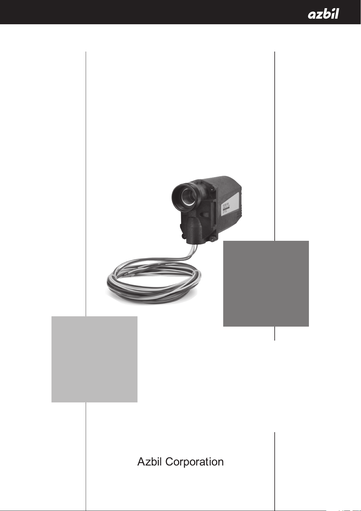
Advanced Ultraviolet
Flame Detector
User’s Manual
No. CP-SP-1141E
Thank you for purchasing an Azbil
Corporation product.
This manual contains information for
ensuring the correct use of this product.
It also provides necessary information
for installation, maintenance, and
troubleshooting.
This manual should be read by those who
design and maintain equipment that uses
this product. Be sure to keep this manual
nearby for handy reference.
Page 2

NOTICE
Be sure that the user receives this manual before the product is used.
Copying or duplicating this user’s manual in part or in whole is forbidden.
The information and specifications in this manual are subject to change
without notice.
Considerable effort has been made to ensure that this manual is free from
inaccuracies and omissions. If you should find an error or omission, please
contact the azbil Group.
In no event is Azbil Corporation liable to anyone for any indirect, special or
consequential damages as a result of using this product.
© 2008–2016 Azbil Corporation All Rights Reserved.
Page 3
Conventions Used in This Manual
The safety precautions explained in the following section aim to prevent injury to the operator and
others, and to prevent property damage.
Warnings are indicated when mishandling this product might
WARNING
CAUTION
In describing the product, this manual uses the icons and conventions listed below.
Use caution when handling the product.
The indicated action is prohibited.
Always follow the indicated instructions.
Handling Precautions:
Handling Precautions indicate items that the user should pay attention to when handling
the AUD300C1000.
result in death or serious injury.
Cautions are indicated when mishandling this product might
result in minor injury to the user, or physical damage to the
product.
Note:
(1), (2), (3): Numbers within parentheses indicate steps in a sequence or parts of an explanation.
>>: Indicates the result of an operation, details displayed on the personal computer or other
Notes indicate information that might benefit the user.
This indicates the item or page that the user is requested to refer to.
devices, or the state of the device after operation.
i
Page 4
Safety Precautions
Use this device only in combination with Azbil Corporation’s burner controllers.
Make sure that this device does not detect ultraviolet rays other than those of the burner flame.
If it responds to other ultraviolet radiation, flame failure in the burner will not be detected.
As a result, the outflow of fuel will continue, causing a very serious explosion hazard.
Before removing, mounting, or wiring this device, be sure to turn off the power to the device
and all connected devices. Failure to do so may cause electric shock.
Before doing any wiring work, be sure to disconnect the power to prevent electrical shock.
To prevent explosion, carry out the pilot turndown test carefully. If this device detects a pilot
flame that is too small to ignite the main burner, the burner controller will not be able to
recognize flame failure of the main burner, allowing the outflow of fuel to continue, leading to
a serious explosion hazard.
If the pilot turndown test is carried out repeatedly, completely shut down all equipment each
time the test is finished, and completely discharge unburned gas or fuel that has accumulated
in the combustion chamber and flue. If unburned gas and oil are not discharged completely,
an explosion may occur.
WARNING
Do not touch terminals F or G on this device or on the burner controller immediately after the
power to the burner controller has been turned OFF. There is a danger of electric shock because
terminals F and G retain a charge for up to 1 minute after the power has been turned off.
When measuring the voltage between terminal F and terminal G of this device in order to check
the wiring, do not touch any part of the terminals. Doing so may result in an electric shock.
Do not use this device with the cover removed. Doing so may result in an electric shock. If the
cover has been removed from this device, be sure to reattach it and tighten the four mounting
screws completely before use.
ii
Page 5
CAUTION
This device is designed for both batch operation of the burner (at least one start and stop in a
24-hour period) and continuous operation (nonstop combustion for 24h or longer). It must be
used with a burner controller having a dynamic self-checking function.
Installation, wiring, inspection, adjustment, etc., should be carried out by a trained and
experienced technician with knowledge and technical skills related to combustion equipment
and flame safeguard control devices.
Do not install where the product will be exposed to any of the following:
•
Certain chemicals or corrosive gases (ammonia, sulfur, chlorine, ethylene compounds, acid, etc.).
•
Splashing water or excessive humidity
•
High temperatures
•
Prolonged vibration
If this device is operated in an atmosphere where there is steam, sooty smoke, oil mist, dust,
and/or organic solvents that interfere with ultraviolet rays, take appropriate corrective
measures.
When using multiple burners, mount this unit in a position where it can detect only the flame
of the burner to be monitored.
Carry out the wiring work in conformity with the specified standards.
Be sure to route the signal wires of this device separately from high-voltage ignition
transformer cables and power cables, and put them in a separate conduit.
After the wiring work is complete, be sure to check that there are no mistakes. Incorrect wiring
can cause damage or malfunction.
Only an experienced technician with knowledge and technical skills related to combustion
equipment and combustion safety should carry out the pilot turndown test.
Do not transport this device while it is mounted on the combustion equipment. Shock or
vibration during transport may cause it to malfunction. Before transporting, dismount it and
put it in its specially designed shipping box.
The service life of the tube unit and shutter unit components of this device is a maximum
of 3 years. To ensure operational safety, be sure to replace these units with new ones within
the service life period. For replacement, use the AUD Maintenance Kit (AUD60A1000), which
includes the tube and shutter units.
iii
Page 6
The Role of This Manual
A total of 4 different manuals are available for the AUD300C1000, AUR300C. Read them as necessary for your specific requirements. If a manual you require is not available, contact the azbil Group or its dealer.
AUD300C1000 Advanced Ultraviolet Flame Detector
Manual No.CP-SP-1141E
This manual.
The manual describes the mounting, wiring, maintenance and inspection, and troubleshooting when the AUD300C is built-into the combustion equipment.
AUR300C Advanced Ultraviolet Burner Controller
Manual No.CP-SP-1142E
The personnel in charge of design, mounting, operation, and maintenance of the
combustion equipment using the AUR300C must read this manual.
The manual describes the mounting, wiring, trial-run adjustment, and maintenance and inspection of the AUR300C.
AUR350C Advanced Ultraviolet Burner Controller with Communications
Manual No.CP-SP-1175E
Personnel in charge of design, mounting, operation, and maintenance of combustion equipment using the AUR350C should read this manual.
It describes the mounting, wiring, trial-run adjustment, maintenance, inspection
of the AUR350C.
AUR450C Dynamic Self-Checking Burner Controller
Manual No. CP-SP-1264E
This manual should be read by personnel using the AUR450C for the first time,
those in charge of designing combustion equipment that uses the AUR450C or
designing the hardware for mounting the device in a control panel, and personnel
performing maintenance.
The manual gives an overview of the product, its mounting and wiring for connection to other equipment, its operation, trial-run adjustment, maintenance and
inspection, and specifications.
iv
Page 7

Contents
Conventions Used in This Manual
Safety Precautions
The Role of This Manual
Chapter 1. OVERVIEW
Overview
Features 1
Names of parts 1
Model selection table 1
1
1
Chapter 2. MOUNTING 3
What to know before installation
Methods of monitoring burner flame 4
Mounting position 4
Mounting orientation 5
Mounting of the monitoring pipe 6
Mounting procedure 8
3
Chapter 3. WIRING 9
Wiring diagram
Wiring check 10
9
Chapter 4. ADJUSTMENT 11
Before measuring the flame voltage
Measuring the flame voltage 11
Pilot turndown test 12
Ignition spark response test 13
Permanent mounting of monitoring pipe 13
Final check 13
11
Chapter 5. TROUBLESHOOTING 14
Troubleshooting procedure
14
Chapter 6. MAINTENANCE AND INSPECTION 15
Periodic inspection
Replacement of the shutter unit and tube unit using the AUD Maintenance Kit
(AUD60A1000) 16
v
15
Page 8

Chapter 7. SPECIFICATIONS 19
Specifications
External dimensions 20
Terms and Conditions
19
vi
Page 9
Chapter 1.
■ Overview
■ Features
OVERVIEW
The AUD300C1000 Advanced Ultraviolet Flame Detector (hereafter this/the device) is designed to detect ultraviolet radiation from an oil or gas burner flame, for
use with both batch and continuous operation burners. The AUD300C1000 is used
in combination with a dedicated burner controller. By means of the built-in shutter,
any malfunction of the UV flame detector or burner controller is detected by the
start check and continuous self-checking function (Dynamic Self-Check), ensuring
highly reliable combustion safety control.
•
Maintenance parts such as the tube unit and shutter unit can be handled as a
single unit. This ensures easy replacement and maintenance work.
•
As for a flame sensor for the self-check, this unit is compact and lightweight. This
ensures free burner mounting.
•
The operating ambient temperature is 100°C (up to 120°C during flame detection) and the protection structure is IP66. This ensures excellent environmentproof performance.
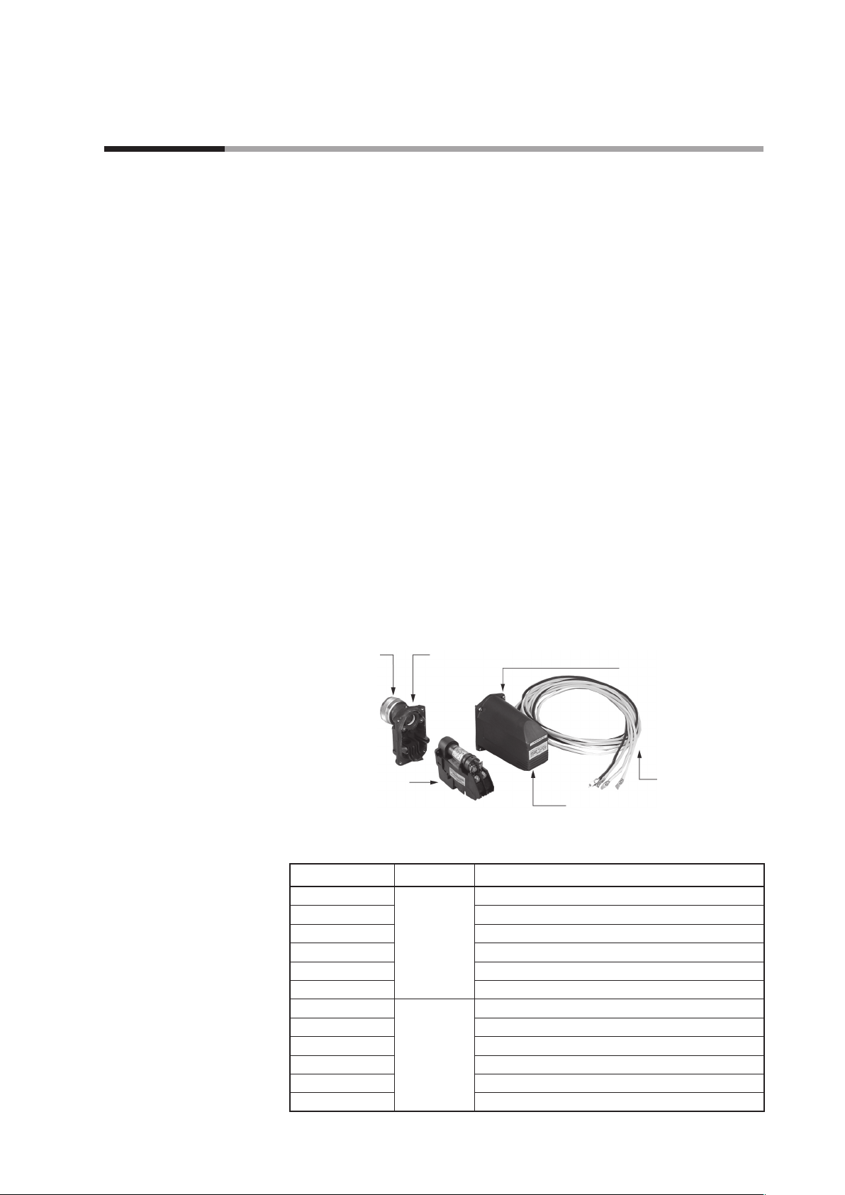
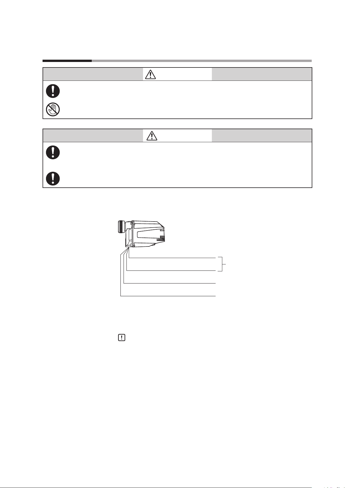
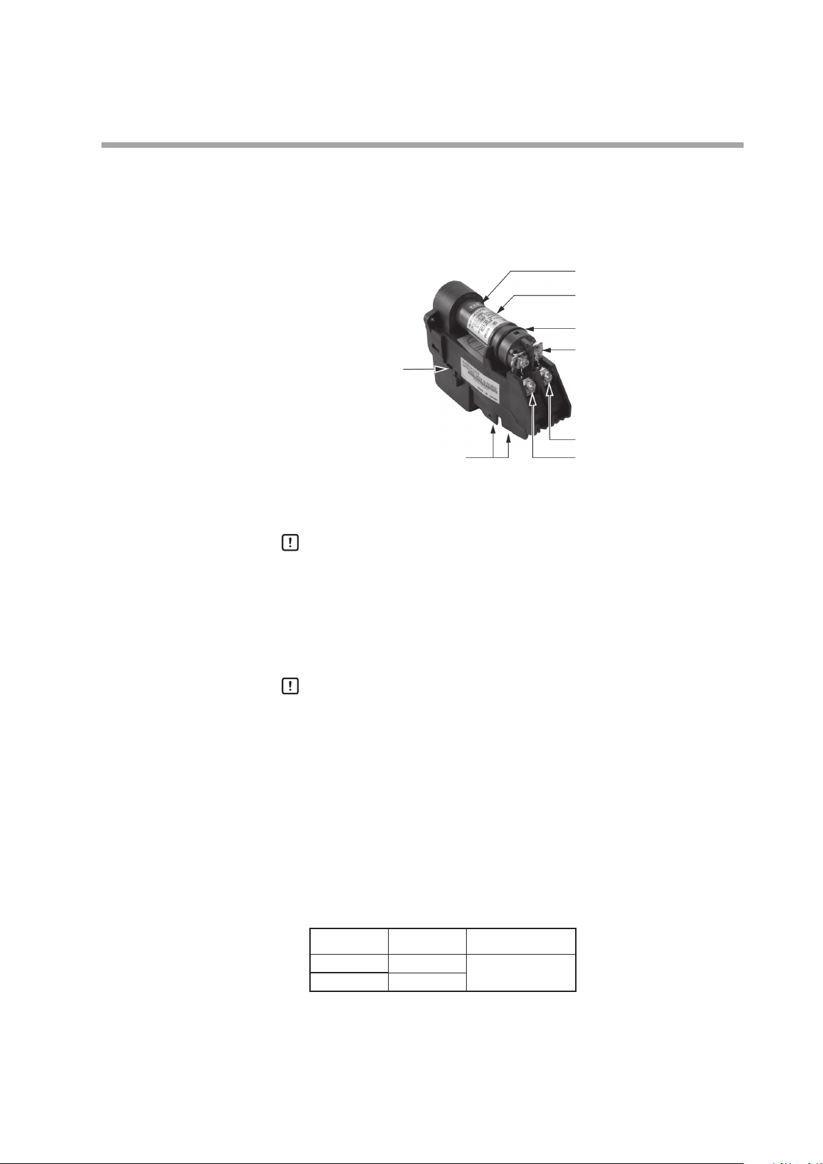
■ Names of parts
● Main unit
■ Model selection table
•
Because it can be mounted vertically and has a maximum wire length of 200m,
flexible installation is possible.
Mounting nut
AUD Maintenance Kit
AUD60A1000
Model No. Lens type Additional
AUD300C1000 Standard None
AUD300C100D Inspection report
AUD300C100T Tropicalization treatment
AUD300C100Y Traceability certificate
AUD300C100DT Inspection report + tropicalization treatment
AUD300C100YT Traceability certificate + tropicalization treatment
AUD300C1100 Condenser None
AUD300C110D Inspection report
AUD300C110T Tropicalization treatment
AUD300C110Y Traceability certificate
AUD300C110DT Inspection report + tropicalization treatment
AUD300C110YT Traceability certificate + tropicalization treatment
Flange unit: 81446924-001 or -101
Cover mounting screws (4)
Lead wires
Cover
1
Page 10
Chapter 1. OVERVIEW
Certification
Combined burner controller
•
UL: File No. MH27717
•
CSA: Master Report LR 078402
•
CE*: Gas Appliance Directive
0063BS1427 (with AUR450C_2_____and Q241A104)
0063CN6671 (with RX-R4_C_____)
RoHS Directive
*CE marking appears to comply with RoHS
Model Name
RX-R40, RX-R44, RX-R46 Burner Control Module
AUR300C, AUR350C Advanced Ultraviolet Burner Controller
AUR450C Dynamic Self-Checking Burner Controller
Maintenance/optional parts
AUD60A1000 AUD Maintenance Kit *
81446924-001 Flange unit (Standard type)
81446924-101 Flange unit (Condenser type)
81447495-001 Nut packing
81447509-001 Bushing 1×3/4
FSP136A100 Analog flame meter
*1 AUD60A1000 Maintenance Kit
The AUD Maintenance Kit incorporates the tube and shutter units (tube unit: AUD10,
shutter unit: AUD50), including expendables like the expiration date label*
O-ring used for sealing between the flange and cover of the AUD.
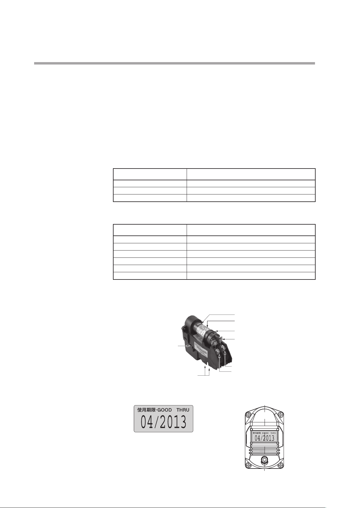
Terminal for shutter driver connection
(white lead wire)
Model Name
1
Thermolabel
Label
Tube unit
Tube unit retaining screws (2)
Shutter unit
Terminal G (yellow lead wire)
Terminal F (blue lead wire)
2
and the
*2 Expiration date label Position of the expiration date label
2
Page 11

Chapter 2.
Before mounting or removing, be sure to turn off the power to this device and all connected
devices. Failure to do so may result in electric shock.
If this device is installed near a source of ultraviolet rays other than the burner flame or in an
atmosphere that interferes with UV rays, as described below, take sufficient countermeasures.
•
Near sources of ultraviolet rays, such as red-hot furnace walls (1371°C or more)
•
Near sources of gamma rays or x-rays, such as diffraction analyzers, electron microscopes, x-ray
machines, high-voltage vacuum switches, high-voltage capacitors, radioactive isotopes, etc.
•
In atmospheres that interfere with ultraviolet rays, due to steam, sooty smoke, oil mist, dust, etc.
Install the flame detector at an angle that does not allow the ignition spark to be detected.
Make sure that this device does not detect ultraviolet rays other than those of the burner flame.
If it responds to other ultraviolet radiation, flame failure in the burner will not be detected.
As a result, the outflow of fuel will continue, causing a very serious explosion hazard.
Install this device in accordance with the relevant laws and standards.
MOUNTING
WARNING
CAUTION
When discarding this product, dispose of it as industrial waste, following local regulations.
Installation, wiring, inspection, adjustment, etc., should be carried out by a trained and
experienced technician with knowledge and technical skills related to combustion equipment
and flame safeguard control devices.
If this device is operated in an atmosphere where there is steam, sooty smoke, oil mist, dust, and/
or organic solvents that interfere with ultraviolet rays, take appropriate corrective measures.
When using multiple burners, mount this unit in a position where it can detect only the flame of
the burner to be monitored.
Do not install where the product will be exposed to any of the following:
•
Certain chemicals or corrosive gases (ammonia, sulfur, chlorine, ethylene compounds, acid, etc.).
•
Splashing water or excessive humidity.
•
High temperatures
•
Prolonged vibration
Be sure to observe the ambient temperature indicated in the specifications. Failure to do so may
damage the device or cause faulty operation.
What to know before installation
•
For proper installation of the device, thoroughly read the instruction manuals for
the burner, boiler, and other equipment provided by the combustion equipment
manufacturers. Make an appropriate installation plan according to those instruction manuals.
•
This device must monitor actual flames. Make the mounting position of the device
as close to the flame as possible unless that position affects the equipment layout
around the burner, the operating temperature, etc. The shorter the distance between
the device and the burner nozzle, the more ultraviolet radiation can be detected.
•
Mount this device away from the ignition transformer. Mount the ignition transformer as close to the burner as possible, and be sure to ground the transformer.
3
Page 12

Chapter 2. MOUNTING
Methods of monitoring burner flame
Monitoring of the pilot flame only (continuous, intermittent pilots)
The main burner must be reliably ignited even with the smallest pilot flame that
this device can detect. For this reason, throttle the pilot manual fuel valve so that
the main burner can be barely ignited. Under this condition, adjust the device so
that only the tip of the pilot flame is monitored. Adjust the device so that the monitored area is as close to the tip of the flame as possible, and is also along the axis of
the pilot flame.
Monitoring of both pilot and main flames (continuous, intermittent pilots)
Adjust the device so that it monitors the area where the pilot and the main flames
overlap.
Monitoring of main flame only (interrupted pilot)
Adjust the device so that it monitors the part of the main flame that is the most
stable in any combustion condition (low fire, high fire, etc.). In special combustion
conditions, the use of two detectors is recommended in order to monitor the low
and high fire positions separately.
Separate monitoring of pilot and main flames (continuous, intermittent pilots)
Make sure that the detector monitoring the main flame cannot mistakenly detect
the pilot flame. If it detects the pilot flame when there is a flame failure of the main
burner, the flame failure will not be detected, and the fuel supply will not be shut off.
Monitoring if there are multiple burners in the same combustion chamber
Mount a UV sensor on each burner, making sure in each case that another burner’s
flame is not detected.
Note that there is an electrical discharge inside this device’s tube unit while a flame
is detected. Since ultraviolet rays are emitted from the tube due to this electrical discharge, if multiple detectors are used, their position must be adjusted so that detectors cannot detect ultraviolet rays emitted from the tube unit of other detectors.
Redundant system (redundant monitoring)
Redundant monitoring is recommended to avoid unnecessary shutoff as much as
possible and to ensure the reliability of the system. A redundant system can be made
if two pairs of this device plus a burner controller are used to monitor the flame of
one burner. If either flame detector does not output a flame signal or if there is a
false flame signal, an alarm will be generated, but combustion will continue.
If both burner controllers detect a flame failure at the same time, the combustion
system will be shut down. This kind of redundant system prevents unnecessary
shutoff caused by flame fluctuation or a malfunction of this device or of the burner
controller.
Mounting position
Temperature
4
Taking the following items into account, determine the optimal mounting position.
Mount this unit in a place where the ambient temperature during operation is
−20to +100°C (up to 120°C during flame detection).
Page 13

Handling Precautions
Vibration
Chapter 2. MOUNTING
•
If the above temperature range is not observed, a malfunction of the tube unit
or shutter unit of this device, or unnecessary shutoff, may occur.
•
When this unit is not being used to detect a flame, do not allow the ambient
temperature to exceed 100°C. While power is being supplied, an ambient
temperature over 100°C causes breakdown of the insulation on the internal
coil and, when the unit resumes operation (flame detection), faulty shutter operation (failure to open).
•
If the actual temperature is expected to be outside of the operating temperature range, provide a shielding plate between the combustion chamber and
this device, or use air purging or the like so that the temperature is within the
operating temperature range.
2
Mount the device in a location where the acceleration is 4.9m/s
or less.
Handling Precautions
Outdoor use
Handling Precautions
Mounting orientation
Mounting pipe
•
Vibration may shorten the service life of the tube unit or shutter unit, or may
cause faulty operation or malfunction.
Provide a roof, etc., to protect against rain.
•
The surface of the case may change color due to sunshine or other causes.
However, this will not affect the functioning of the product.
Mount this device with the opening for the electrical wiring conduit facing downward, aligned in a vertical plane.
Do not tilt
OK
Mounting nut
Conduit tube connection port
Vertical plane mounting
Front side
Do not mount
horizontally
Do not
mount upside-down
5
Page 14

Chapter 2. MOUNTING
The allowable range of the mounting posture is that the upper limit is 90° (conduit
tube port becomes horizontal) and the lower limit is 45°.
Upper limit 90°
90°
Horizontal
plane
45°
Handling Precautions
•
Mount this device so that it monitors the burner at an angle from above. If it
monitors the burner at an angle from below or from the same level, dust, soot,
etc., will accumulate on the monitoring window or in the monitoring pipe. This
may block the ultraviolet rays, preventing flame detection.
Mounting of the monitoring pipe
Monitoring pipe materials
Use a mounting pipe with a black inside wall. If the inside wall of the pipe has a
stainless steel or electroplated surface, ultraviolet rays will be reflected irregularly
inside the pipe, causing a malfunction.
Monitoring pipe size
To detect a large amount of ultraviolet radiation from the flame, this device’s lightreceiving surface must have a wide field of view. If the recommended flame voltage
of 2.0VDC cannot be ensured, change the monitoring pipe to a wider one so that
sufficient ultraviolet radiation is received.
Side
Vertical
plane
Lower limit 45°
•
Use as large a monitoring pipe as possible. Connect the pipe to the device using a
reducer.
•
Make the length of the monitoring pipe as short as possible. However, always
keep the operating ambient temperature within 100°C (up to 120°C during
flame detection).
6
Page 15

Mounting space
used to supply the air.
Flame surface area monitored is large and much ultraviolet radiation is detected.
Chapter 2. MOUNTING
Leave a sufficient space for easy maintenance, inspection, and service work.
Monitoring pipe, 1" or more (Use 2" to 3" pipe.)
Handling Precautions
Reducing socket
Tees
*
Burner
*
Air
Connection
nipple (1")
* If the air purging is needed, tees are
Furnace wall
Tapered monitoring hole
Weld this
part
Plate
•
Mount this device so that it monitors the burner at an angle from above. If it
AUD300C
monitors the burner at an angle from below or from the same level, dust, soot,
etc., will accumulate on the monitoring window or in the monitoring pipe. This
may block the ultraviolet rays, preventing flame detection.
•
Mount this device so that its monitoring orientation intersects the flame
axis at as small an angle as possible. This maximizes the overlap between the
flame and the area monitored by the device. Thus, the amount of detected ultraviolet rays also increases.
Good sighting position
(low angle sighting)
Poor sighting position
Unburnt fuel
Burner
Flame surface area monitored is small.
7
Page 16
Chapter 2. MOUNTING
Temporary welding for monitoring pipe positioning
(1) Preparing a monitoring pipe and making the mounting hole
Make the mounting hole at the selected location for the monitoring pipe. Cut
threads on one end of the monitoring pipe and cut it to the desired length,
making it as short as possible.
(2) Welding the monitoring pipe temporarily
Weld the monitoring pipe temporarily to the
plate of the combustion chamber of the
boiler, etc. Do not weld the monitoring pipe
completely at this time, because inspection
and adjustment are required for
successful flame detection.
(3) Carry out the air purging of the monitoring pipe.
The air purging of the inside of the monitoring pipe is useful to cool this unit
and keep the monitoring area clean.
In particular, if the ambient temperature of this unit exceeds 120°C, the cooling, such as air purging is needed.
•
If the inside of the furnace is a type of induction, make an air purging hole
in the monitoring pipe.
•
If the forced type furnace is used, connect an air purging supply pipe.
Furnace wall
(refractories)
Monitoring pipe
Temporary
welds
Plate
Mounting procedure
Check item
Mounting
When mounting the AUD300C on a monitoring pipe, proceed as follows:
File the monitoring pipe in advance to eliminate burrs and protrusions.
(1) Hold the unit securely with one hand to prevent it from rotating.
(2) Tighten the mounting nut approximately 4 turns with the other hand until the
unit is held securely in place.
(3) Make sure the unit is properly aligned in the vertical plane when viewed from
the front. (
Mounting orientation (P.5))
Handling Precautions
•
Be sure the AUD300C is properly aligned vertically when seen from the
front. If not, the shutter in the shutter unit may be damaged or malfunction.
•
If this unit is not mounted correctly, this may cause the shutter of the shutter unit to be damaged or malfunction.
•
File any burrs or protrusions from the monitoring pipe. If the packing in the
mounting nut is damaged, any chance of leakage may be caused.
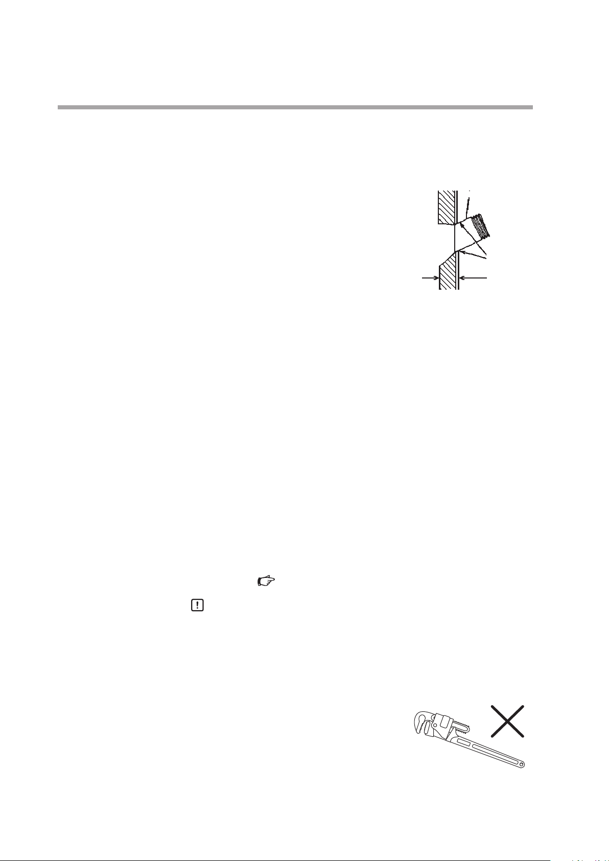
•
Do not use a tool such as pipe wrench when
tightening the mounting nut. Excessive
torque by a tool could damage the packing
and compromise the seal.
•
Do not adjust the mounting pose by forcibly
holding the unit or wiring pipe. Failure to do so may damage the packing
and compromise the seal.
8
Page 17
Chapter 3.
AUD300C
Before doing any wiring work, be sure to disconnect the equipment power to prevent electrical
shock.
When measuring the voltage between terminal F and terminal G of this device in order to check
the wiring, do not touch any part of the terminals. Doing so may result in an electric shock.
Installation, wiring, inspection, adjustment, etc., should be carried out by a trained and
experienced technician with knowledge and technical skills related to combustion equipment
and flame safeguard control devices.
Be sure to route the signal wires of this device separately from high-voltage ignition transformer
cables and power cables, and put them in a separate conduit.
Wiring diagram
WIRING
WARNING
CAUTION
White
White
Yellow
Blue
Run all wires connected to the burner controller through wiring conduits and conduit boxes. Also, be sure to route power wiring to the controller separately from
other power wires.
Handling Precautions
•
Do not run the wiring to this device in the same wiring conduit as power
lines or high voltage cables from the ignition transformer.
•
Put high-voltage ignition transformer cables and the ground wire in the
same conduit, and ground one end of the conduit. If an automotive spark
plug is used, pay special attention to wiring.
•
If the surge from the ignition transformer adversely affects the detector,
ground both ends of the conduit between the detector and the burner
controller, or change the cable routing.
Shutter output
terminal
(G)
(F)
9
Page 18

Chapter 3. WIRING
Wiring check
Steps
Before applying voltage to this device, check that the wiring is correct.
(1) In the relay box, disconnect the blue and yellow wires that come from the
AUD300C.
(2) Turn on the power to the burner controller.
(3) Measure the DC voltage between terminals F and G in the relay box using a
circuit tester or a digital voltage meter.
(4) Connect the + tester probe to terminal G (yellow wire) and the – tester probe
to terminal F (blue wire).
>> If the reading is between 160 and 220 V DC, the leads are connected cor-
rectly. If a negative voltage is measured, terminals F and G are reversed.
(5) Next, measure the DC voltage (shutter voltage) between terminals S1 and S2
(both wires are white).
Handling Precautions
•
Terminals S1 and S2 do not have a specified polarity. When using a multimeter, before measuring the shutter voltage, check the polarity using
a wide voltage range so that the needle does not go off the scale on the
minus side.
>> If the reading is between 15 and 24VDC, the leads are connected cor-
re c tly. * If the meter indicates a constant voltage, either 24 or 0VDC, the
cause is probably a wiring mistake.
* If there is a flame, the shutter voltage fluctuates within the 0–24VDC range.
(6) In the relay box, reconnect the blue and yellow wires that come from the
AUD300C one minute or longer after the power to the burner controller has
been turned OFF.
Handling Precautions
•
Terminals F and G retain an electrical charge for about 1 minute after the
power has been turned off. Within this time, touching terminal F or G may
result in electric shock.
10
Page 19
Chapter 4.
ADJUSTMENT
Before measuring the flame voltage
Before measuring the flame voltage, execute an operational check of this device
using the flame voltage output terminals of the burner controller.
Model No. Flame voltage output terminals
AUR300C
AUR350C
AUR450C Positive terminal, Negative terminal
(1) Connect an analog flame meter (FSP136A100) to the flame voltage output ter-
minals of the burner controller.
(2) Light a lighter in front of the ultraviolet ray receiving part of this unit to check
that the voltage is output correctly.
Handling Precautions
•
Before using fire, check that there is no flammable gas around this device.
Terminal 9 (+)
Terminal10 (−)
Measuring the flame voltage
If there are both pilot and main flames, measure the voltage of each. Measure the
flame voltage for the maximum (high fire) and minimum (low fire) combustion.
(1) Mount this device on the monitoring pipe temporarily.
(2) Start burner combustion.
(3) To determine an optimal monitoring position, measure the flame voltage of
the burner controller with the analog flame meter (FSP136A100) while moving the monitoring pipe position little by little in order to find a position where
as highly stable voltage as possible is shown.
Recommended flame voltage Inspection item
The flame voltage must be stable at
2.0VDC or more.
(It may fluctuate in a range of 0.1–0.3V
synchronized with the shutter operation
of this device.)
Handling Precautions
•
If the flame voltage exceeds 4V, install an orifice to limit the amount of ultraviolet radiation. If the amount of ultraviolet radiation is too large, UV rays may
enter the tube unit due to diffuse reflection even when the shutter is closed,
causing a malfunction.
•
Is the flame properly monitored?
•
Is the detector’s light-receiving lens clean?
•
Is there accumulated soot, etc., in the
monitoring pipe?
11
Page 20
Chapter 4. ADJUSTMENT
Pilot turndown test
To prevent explosion, carry out the pilot turndown test carefully. If this device detects a pilot
flame that is too small to ignite the main burner, the burner controller will not be able to
recognize flame failure of the main burner, allowing the outflow of fuel to continue, leading to a
serious explosion hazard.
If the pilot turndown test is carried out repeatedly, completely shut down all equipment each
time the test is finished, and completely discharge unburned gas or fuel that has accumulated
in the combustion chamber and flue. If unburned gas and oil are not discharged completely, an
explosion may occur.
This test is intended to check that any pilot flame detected by this device will reliably ignite the main burner, even if the gas pressure and air pressure have changed
to their worst possible conditions.
WARNING
CAUTION
Installation, wiring, inspection, adjustment, etc., should be carried out by a trained and
experienced technician who has knowledge and technical skills related to combustion
equipment and flame safeguard control devices.
Only an experienced technician who has knowledge and technical skills related to combustion
equipment and combustion safety should carry out the pilot turndown test.
For the pilot turndown test procedure, follow the user’s manual of the burner controller used with this device or the instruction manual provided by the combustion
equipment manufacturer.
12
Page 21
Chapter 4. ADJUSTMENT
Ignition spark response test
WARNING
Make sure that this device does not detect ultraviolet rays other than those of the burner flame.
If it responds to other ultraviolet rays, flame failure in the burner will not be detected. As a result,
fuel will continue to be discharged, causing a very serious explosion hazard.
Steps
(1) Close the manual shutoff valves of the pilot and main burners.
(2) Start the burner so that ignition is attempted. When the ignition spark is gen-
erated, check that the flame relay of the burner controller does not turn ON.
(K2 is the flame relay for the AUR300C/350C, and K6 is the flame relay for the
AUR450C.)
(3) If the flame relay turns ON, adjust the monitoring point of this device to avoid
effects from the ignition spark and its reflection.
Handling Precautions
•
The following shows various sources other than flame that may activate
this device. Check that the device’s operation is not affected by these
sources under any operating conditions.
Example:
Ultraviolet ray sources Red-hot furnace walls at 1370°C or more
Ignition transformer and welding arc spark
Gas lasers
Sunlamps
Disinfecting lamps, UV lamps, fluorescent lamps
Strong flashlights (toward UV sensor)
Gamma and x-ray sources X-ray and gamma diffraction analyzers
Electron microscopes
X-ray cameras
High-voltage vacuum switches
High-voltage capacitors
Radioactive isotopes
Any other sources of UV rays, gamma rays, or X-rays
Permanent mounting of monitoring pipe
(1) After all adjustments have been done, if the equipment operates properly with
the specified flame voltage output, turn OFF the power to the equipment, remove the detector, and weld the monitoring pipe permanently.
(2) Remount the device on the monitoring pipe securely and do all wiring.
Final check
For reliable burner control, run the equipment through at least one cycle to check
all control operations.
13
Page 22
Chapter 5.
Before removing, mounting, or wiring this device, be sure to turn off the power to the device and
all connected devices. Failure to do so may cause electric shock.
Do not touch terminals F or G on this device or on the burner controller immediately after the
power to the burner controller has been turned OFF. There is a danger of electric shock because
terminals F and G retain a charge for up to 1 minute after the power has been turned off.
Installation, wiring, inspection, adjustment, etc., should be carried out by a trained and
experienced technician with knowledge and technical skills related to combustion equipment
and flame safeguard control devices.
Required items
TROUBLESHOOTING
WARNING
CAUTION
•
Analog flame meter FSP136A100
•
Maintenance/optional parts (P.2)
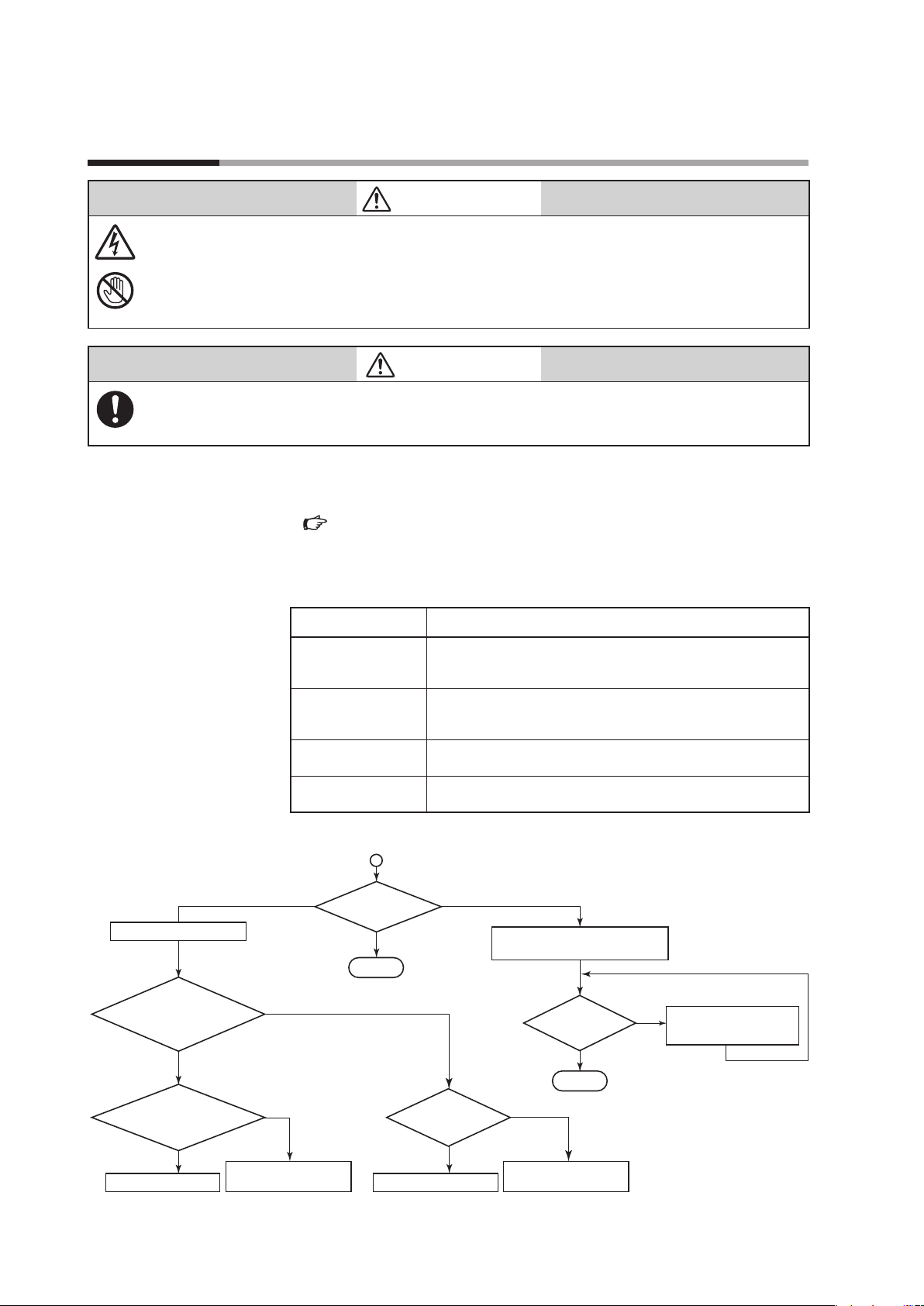
Troubleshooting procedure
(1) Check the following operating conditions.
Supply power
Wiring
Ambient temperature
Ambient humidity
(2) Check the device according to the flowchart below.
Zero
Remove the tube unit.
Does
shutter open when
burner controller power
is ON?
Yes (open)
Check
voltage betw. terminals
F and G.*
2
No (closed)
NG
Item What to Check
•
Is the power switch ON?
•
Are power terminal screws loose?
•
Is the voltage within the allowable range?
•
Do wires go to the right terminals?
•
Is there a broken wire?
•
Is there deteriorated or damaged insulation?
•
Check that the temperature is +100°C or less. (up to 120°C
during flame detection)
•
Is the ambient humidity no higher than 90% RH?
•
Is there condensation inside the device?
Flame voltage
check*
OK
Normal
1
Check
shutter voltage.*
• Clean monitoring window.
• Clean inside monitoring pipe.
3
Low
Flame voltage
check*
OK
Normal
NG
1
NG
Adjust the monitoring
position and/or burner.
OK
Replace tube unit.*
*1. 2.0VDC or more is normal. *2. 160–220VDC is normal. *3. Fluctuation between 0V and 15–24VDC is normal.
*4. When replacing the tube unit, replace the shutter unit also. When replacing the shutter unit, replace the tube unit also.
Check wiring / replace
4
burner controller.
Replace shutter unit.*
OK
Check wiring / replace
4
burner controller.
14
Page 23
Chapter 6.
Before mounting, removing, or wiring this device, be sure to turn OFF the power to the module
and any connected devices. Failure to do so may result in an electric shock.
Do not touch terminals F or G on this device or on the burner controller immediately after the
power to the burner controller has been turned OFF. There is a danger of electric shock because
terminals F and G retain a charge for up to 1 minute after the power has been turned off.
Do not use this device with the cover removed. Doing so may result in an electric shock. If the
cover has been removed from this device, be sure to reattach it and tighten the four mounting
screws completely before use.
Installation, wiring, inspection, adjustment, etc., should be carried out by a trained and
experienced technician with knowledge and technical skills related to combustion equipment
and flame safeguard control devices.
The service life of the tube unit and shutter unit components of this device is a maximum of
3years. To ensure operational safety, be sure to replace them with new ones within the service
life period. For replacement, use the AUD Maintenance Kit (AUD60A1000), which includes the
tube and shutter units.
MAINTENANCE AND INSPECTION
WARNING
CAUTION
Periodic inspection
(1) Turn off the power to the burner controller.
(2) Clean the monitoring window and monitoring pipe periodically.
(3)
(4) Adjust the burner so that it operates properly as recommended by the burner
Maintenance and inspection cycle
Dirty monitoring window and monitoring pipe, loose screws Once a month or more
Safety shutoff test Once a month or more
Measurement of flame voltage Once a month or more
Pilot turndown test Once a year or more
Remove the device from the monitoring pipe and clean the inside of the monitoring pipe and the quartz glass with a clean cloth.
To check the function of the tube unit, periodically conduct a safety shutoff test.
AUR300C Advanced Ultraviolet Burner Controller User’s Manual, No. CP-
SP-1142E
AUR350C Advanced Ultraviolet Burner Controller with Communications
User’s Manual, No. CP-SP-1175E
AUR450C Dynamic Self-Checking Burner Controller User’s Manual, No.
CP-SP-1264E
manufacturer.
Points to check Frequency
15
Page 24
Chapter 6. MAINTENANCE AND INSPECTION
Handling Precautions
•
If burner shutoff will cause serious loss, conduct inspection more frequently.
•
If the burner manufacturer provides specific instructions for maintenance and
inspection, be sure to observe them.
•
For inquiries about device failure, repair service, etc., contact the azbil Group.
Replacement of the shutter unit and tube unit using the AUD Maintenance Kit
(AUD60A1000)
CAUTION
The service life of the tube unit and shutter unit components of this device is a maximum of
3 years. To ensure operational safety, be sure to replace these units with new ones within the
service life period. For replacement, use the AUD Maintenance Kit (AUD60A1000), which includes
the tube and shutter units.
AUD Maintenance Kit
The AUD Maintenance Kit incorporates the tube and shutter units, including expendables like the O-ring.
Handling Precautions
•
When replacing, handle the tube unit gently, taking care not to jar it.
•
When attaching the cover after replacement, fit the O-ring onto the flange
unit properly. Failure to do so will impair its sealing performance.
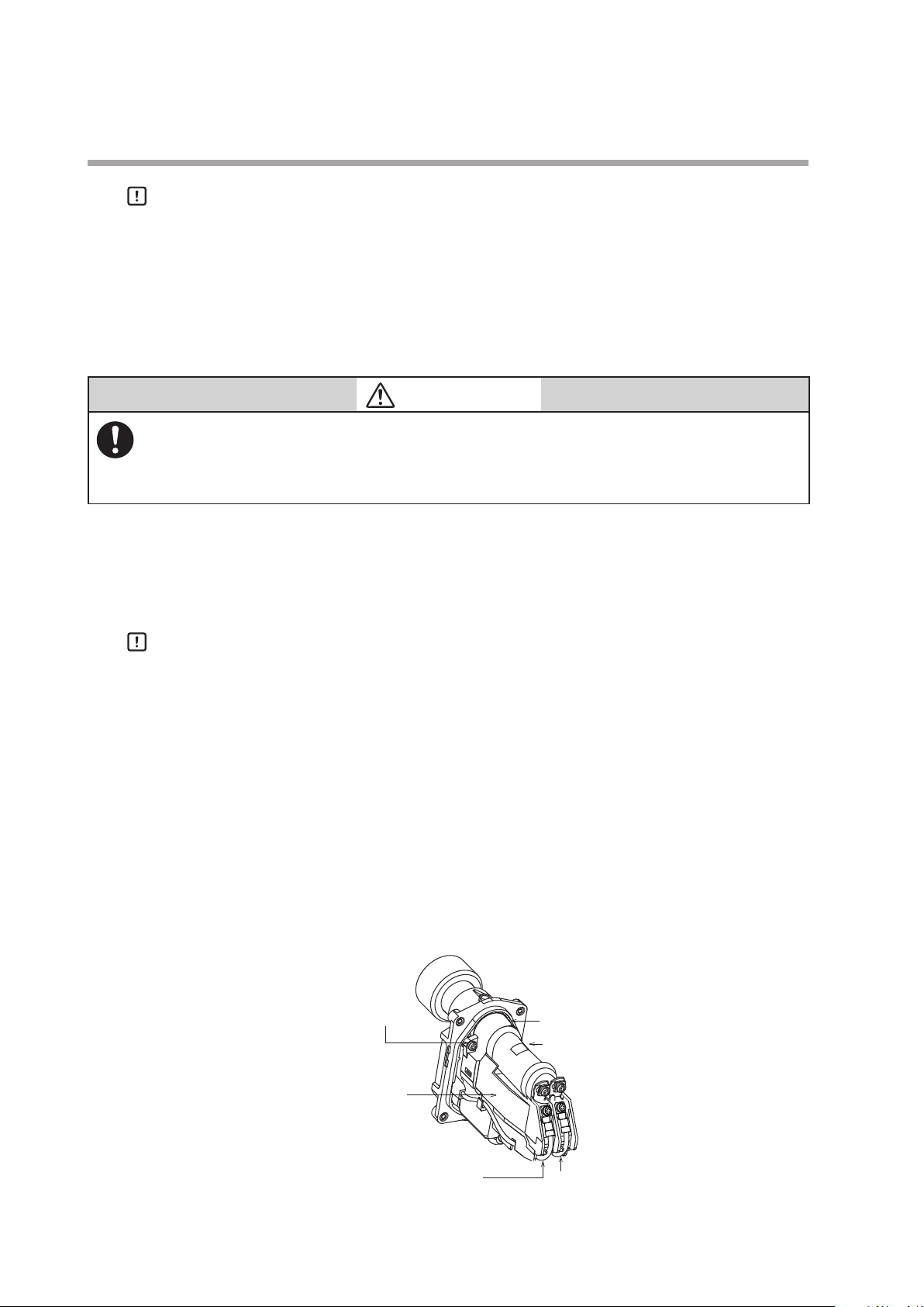
Removing of shutter unit and tube unit
(1) Turn off the power to the burner controller.
(2) After 1 min. has elapsed, remove 4 cover mounting screws to detach the cover.
(3) Remove the 4terminal screws to disconnect the lead wires (2white, 1blue, and
1yellow) from the shutter unit.
(4) Remove the 2shutter unit retaining screws.
(5) Dismantle by separating the flange unit and shutter unit at the top.
16
Shutter unit
retaining screws (2)
Shutter unit
F terminal (blue lead wire)
(6) Remove the O-ring from the flange unit.
O-ring
Tube unit
G terminal (yellow lead wire)
Page 25
Mounting the shutter unit onto the flange unit
(1) Fit the O-ring that is included in the AUD Maintenance Kit onto the flange unit.
(2) Loosen the 2screws holding the new (AUD Maintenance Kit) tube unit and
remove the tube unit, holding it by the back of the unit.
Shutter unit
Chapter 6. MAINTENANCE AND INSPECTION
Thermolabel
Label
Tube unit
Tube unit retaining screw (2)
Terminal for shutter driver connection
(3) After removing the tube unit, mount the shutter unit only on the flange unit
using the 2retaining screws.
Handling Precautions
•
Before mounting, insert the lead wires (blue and yellow) into the slits of
the shutter unit. When mounting the unit onto the flange unit, hold the
white lead wires under the shutter unit so that they stay in the cable guide
groove.
Be sure to connect the lead wires to the 4 terminals of the shutter unit correctly.
(4)
Handling Precautions
•
The blue lead wire goes to terminal F and the yellow one to terminal G.
Connect the two wires according to the “F” and “G” shown on the polarity
indication label on the shutter unit.
Wiring check for tube and shutter units
(1) Turn on the burner controller to check whether terminals F and G are properly
connected.
(white lead wire)
Terminal G (yellow lead wire)
Terminal F (blue lead wire)
(2) Measure the DC voltage between terminals F and G using a multimeter or
digital voltmeter.
(3) Connect the + tester probe (red) to terminal G (yellow lead wire) and the –
tester probe (black) to terminal F (blue lead wire).
Terminal Meter probe Voltage
F − 160–220VDC
G +
>> If the reading is between 160 and 220VDC, the leads are connected cor-
rectly. If a negative voltage is measured, terminals F and G are reversed.
(4) Next, measure the DC voltage (shutter voltage) between terminals S1 and S2
(both lead wires are white).
17
Page 26

Chapter 6. MAINTENANCE AND INSPECTION
Handling Precautions
•
Terminals S1 and S2 do not have a specified polarity. When using a multimeter, before measuring the shutter voltage check the polarity using a wide voltage range so that the needle does not go off the scale on the minus side.
>> If the reading is between 15 and 24VDC, the leads are connected correctly.
If the meter indicates a constant voltage, either 24 or 0VDC, the cause is
probably a wiring mistake.
Mounting the tube unit and cover
(1) Turn OFF the power to the burner controller.
(2) After 1 minute or more, mount the tube unit onto the shutter unit, holding the
back of the tube unit, and tighten the 2 retaining screws to secure the unit.
(3) Make sure that the O-ring has not come off the flange unit.
Handling Precautions
Expiration date label
(4) Attach the cover, and tighten the 4 mounting screws to secure it.
•
The tube unit has polarity. Correctly mount the tube unit on the shutter unit
according to the “F” and “G” shown on the polarity indication label on the top
of the shutter unit. The shutter unit has a stepped surface which fits that of the
tube unit. For that reason the tube unit cannot be mounted the wrong way.
Do not attempt to force it.
•
If the thermolabel attached to the tube unit has changed color from white to
black, the temperature may have exceeded the operating temperature range.
If the ambient temperature of the Advanced Ultraviolet Flame Detector is too
high, cool down the device using air purging or the like. The thermolabel gives
only a rough estimate of the temperature. Check the correct ambient temperature using a thermometer.
•
When mounting the cover, mount the O-ring of the flange unit firmly. Failure
to do so may cause the sealing ability to lower.
•
Tighten the terminal screws and mounting screws with a tightening torque of
0.7N·m.
18
Affix the expiration date label supplied with the AUD Maintenance Kit to the cover
as shown below.
Position of the expiration date labelExpiration date label
Page 27

Chapter 7.
SPECIFICATIONS
Specifications
Item Description
Compatible flame*
Shutter voltage Approx. 24Vdc (supplied from burner controller)
Self-checking cycle Approx. 80 cycles/min
Insulation resistance Between flange unit mounting conduit and F-terminal (or blue lead wire),
Dielectric strength Between flange unit mounting conduit and F-terminal (or blue lead wire),
Operating temperature –20 to +100°C
Storage ambient temperature –20 to +70°C
Storage ambient humidity 90%RH max. at 40°C (without condensation)
Vibration resistance 4.9m/s
Impact resistance 300m/s
Pressure resistance for flange 350kPa
Protective structure IP66 (except a conduit tube connection port)
Mounting orientation –45 to +90° (vertical mounting)
Mounting thread G1 (at the mounting section for monitoring pipe)
Lead wires 18 AWG ETFE color-differentiated wires, length approx. 1.8m
Electric wire pipe mounting conduit 1/2-14NPSM
Allowable wiring length 2.0mm
Material Main body: Heat resistant resin (PPS + PPE + GF40)
Color Brack
Mass Approx. 630g
Effective life of tube and shutter units 3 years
Certification
1
Flame from natural gas, propane gas, kerosene, heavy oil, coke oven gas, hydrogen,
chlorine, ammonia, naphtha, ethylene, etc.
between flange unit mounting conduit and G-terminal (or yellow lead wire),
between flange unit mounting conduit and S1-terminal (or white lead wire),
between flange unit mounting conduit and S2-terminal (or white lead wire):
50MΩ min. by 500Vdc megger at the above each location (also, the tube unit must
be removed)
between flange unit mounting conduit and G-terminal (or yellow lead wire),
between flange unit mounting conduit and S1-terminal (or white lead wire),
between flange unit mounting conduit and S2-terminal (or white lead wire):
1500Vac for 1min or 1800Vac for 1sec at the above each location (also, the tube
unit must be removed)
During flame detection, the maximum allowable ambient temperature is +120°C.
2
max., 10 to 55Hz for 2 hours each in X, Y and Z directions
2
in vertical and horizontal directions
2
600VPVC-insulated cable (IEC 60227-3): 200m max.
Mounting section: Aluminum
Certificates Directive File No. et. al Remarks
UL MH27717
CSA LR078402
CE*
2
GAD (2009/142/EC) 0063BS1427 with AUR450C_2_____
and Q241A104
0063CN6671 with RX-R4_C______
RoHS (2011/65/EU)
*1. In the case of the use of coke oven gas, hydrogen, chlorine, ammonia, naphtha, ethylene, etc., there may be restrictions
on mounting a flame detector, so before use check that flame monitoring is possible.
*2.CE marking appears to comply with RoHS.
19
Page 28

Chapter 7. SPECIFICATIONS
153.5
External dimensions
Unit: mm
54.5
20.5
38.6 dia.
88
(67.5)
Parallel
pipethread
G1
23.7
Conduit tube connection port 1/2-14NPSM
(54.5)
140.0
(104.6)24.5
88
39.5
20
Page 29

Revision History (CP-SP-1141E)
Printed Edn. Revised pages Description
Apr. 2003 1
July 2004 2
Oct. 2006 3
June 2010 4
July 2011 5
Oct. 2011 6
Apr. 2012 7
Oct. 2012 8
Dec. 2012 9
Aug. 2013 10
Dec. 2014 11
Nov. 2016 12
19 Mass 450 g → 630 g
1
2
4
5
6
8
9
10
11
13
16
19
iii
1
2
7
9
15, 16
20
13
20
12
6 to 9
2
19
1
2
19
End of a book
19
End of a book
End of a book
Model No. changed AUD10C to AUD10C1000, AUD300C to
AUD300C1000, AUD50A to AUD50A1000.
List of model No. added.
Cover 81446925-001 and Analog flame meter FSP136A100 added.
● Monitoring of pilot flame and main flame individually added.
Description of ● Redundant system changed.
Description of ● Temperature changed.
● Outdoors added.
Description of Mounting posture changed.
Description of Handling precautions changed.
Figure of mounting space changed.
Description of Handling precautions changed.
Description of ■ Mounting Procedure changed.
■ Wiring diagram; description and figure changed.
■ Checking of wiring; description changed.
■ Before measurement of flame voltage; description changed.
● Procedures; description added.
■ Replacement of table unit; figure changed.
Description of self-checking cycle changed.
Overall revision.
9th item deleted.
Model Nos. added, Model No. table moved from page 2 to page 1.
Standards compliance and Combined burner controller sections added.
Text of sighting position figure revised.
First WARNING revised.
CAUTION revised.
Description of self-checking cycle changed.
Table in Handling Precautions changed.
Description portion of Specification_ambient temperature changed.
Company name changed.
Change in names of parts.
Table for Maintenance/optional parts was changed.
Change in mounting method.
Notes *1 and *2 were added to “Standards compliance.”
Self-checking cycle was changed from 75 to 80.
*2 was changed.
■ Model No. Model No. (AUD300C100YT, AUD300C110YT) added.
● Certification changed.
● Maintenance/optional parts was changed. (81409780-001→81447509-001)
■ Specification “Certification” was changed.
AAS-511A-014-02
■ Specification “Lead wires” was changed. (2.4 m→applox. 1.8 m)
AAS-511A-014-04
Overall revision. 4th ed = 9th Jp ed.
Terms and Conditions were changed (to version No. AA511A-014-09).
Page 30

Terms and Conditions
We would like to express our appreciation for your purchase and use of Azbil Corporation's products.
You are required to acknowledge and agree upon the following terms and conditions for your purchase of Azbil Corporation's
products (system products, field instruments, control valves, and control products), unless otherwise stated in any separate
document, including, without limitation, estimation sheets, written agreements, catalogs, specifications and instruction manuals.
1. Warranty period and warranty scope
1.1 Warranty period
1.2 Warranty scope
Azbil Corporation's products shall be warranted for one (1) year from the date of your purchase of the said products or
the delivery of the said products to a place designated by you.
In the event that Azbil Corporation's product has any failure attributable to azbil during the aforementioned warranty
period, Azbil Corporation shall, without charge, deliver a replacement for the said product to the place where you
purchased, or repair the said product and deliver it to the aforementioned place.
Notwithstanding the foregoing, any failure falling under one of the following shall not be covered under this warranty:
(1) Failure caused by your improper use of azbil product
(noncompliance with conditions, environment of use, precautions, etc. set forth in catalogs, specifications,
instruction manuals, etc.);
(2) Failure caused for other reasons than Azbil Corporation's product;
(3) Failure caused by any modification or repair made by any person other than Azbil Corporation or Azbil
Corporation's subcontractors;
(4) Failure caused by your use of Azbil Corporation's product in a manner not conforming to the intended usage of
that product;
(5) Failure that the state-of-the-art at the time of Azbil Corporation's shipment did not allow Azbil Corporation to
predict; or
(6) Failure that arose from any reason not attributable to Azbil Corporation, including, without limitation, acts of God,
disasters, and actions taken by a third party.
Please note that the term “warranty” as used herein refers to equipment-only-warranty, and Azbil Corporation shall not
be liable for any damages, including direct, indirect, special, incidental or consequential damages in connection with or
arising out of Azbil Corporation's products.
2. Ascertainment of suitability
3. Precautions and restrictions on application
You are required to ascertain the suitability of Azbil Corporation's product in case of your use of the same with your
machinery, equipment, etc. (hereinafter referred to as “Equipment”) on your own responsibility, taking the following
matters into consideration:
(1) Regulations and standards or laws that your Equipment is to comply with.
(2) Examples of application described in any documents provided by Azbil Corporation are for your reference
purpose only, and you are required to check the functions and safety of your Equipment prior to your use.
(3) Measures to be taken to secure the required level of the reliability and safety of your Equipment in your use
Although azbil is constantly making efforts to improve the quality and reliability of Azbil Corporation's
products, there exists a possibility that parts and machinery may break down.
You are required to provide your Equipment with safety design such as fool-proof design, *1 and fail-safe
design*2 (anti-flame propagation design, etc.), whereby preventing any occurrence of physical injuries, fires,
significant damage, and so forth. Furthermore, fault avoidance, *3 fault tolerance,*4 or the like should be
incorporated so that the said Equipment can satisfy the level of reliability and safety required for your use.
*1. A design that is safe even if the user makes an error.
*2. A design that is safe even if the device fails.
*3. Avoidance of device failure by using highly reliable components, etc.
*4. The use of redundancy.
Azbil Corporation's products other than those explicitly specified as applicable (e.g. azbil Limit Switch For Nuclear Energy)
shall not be used in a nuclear energy controlled area (radiation controlled area).
Any Azbil Corporation's products shall not be used for/with medical equipment.
The products are for industrial use. Do not allow general consumers to install or use any Azbil Corporation's product.
However, azbil products can be incorporated into products used by general consumers. If you intend to use a product for
that purpose, please contact one of our sales representatives.
In addition,
you are required to conduct a consultation with our sales representative and understand detail specifications, cautions
for operation, and so forth by reference to catalogs, specifications, instruction manual, etc. in case that you intend to use
azbil product for any purposes specified in (1) through (6) below.
Moreover, you are required to provide your Equipment with fool-proof design, fail-safe design, anti-flame propagation
design, fault avoidance, fault tolerance, and other kinds of protection/safety circuit design on your own responsibility to
ensure reliability and safety, whereby preventing problems caused by failure or nonconformity.
(1) For use under such conditions or in such environments as not stated in technical documents, including catalogs,
specification, and instruction manuals
(2) For use of specific purposes, such as:
* Nuclear energy/radiation related facilities
[For use outside nuclear energy controlled areas] [For use of Azbil Corporation's Limit Switch For Nuclear
Energy]
* Machinery or equipment for space/sea bottom
* Transportation equipment
[Railway, aircraft, vessels, vehicle equipment, etc.]
* Antidisaster/crime-prevention equipment
Page 31

* Burning appliances
* Electrothermal equipment
* Amusement facilities
* Facilities/applications associated directly with billing
(3) Supply systems such as electricity/gas/water supply systems, large-scale communication systems, and traffic/air
traffic control systems requiring high reliability
(4) Facilities that are to comply with regulations of governmental/public agencies or specific industries
(5) Machinery or equipment that may affect human lives, human bodies or properties
(6) Other machinery or equipment equivalent to those set forth in items (1) to (5) above which require high reliability
and safety
4. Precautions against long-term use
5. Recommendation for renewal
6. Other precautions
7. Changes to specifications
Use of Azbil Corporation's products, including switches, which contain electronic components, over a prolonged period
may degrade insulation or increase contact-resistance and may result in heat generation or any other similar problem
causing such product or switch to develop safety hazards such as smoking, ignition, and electrification.
Although acceleration of the above situation varies depending on the conditions or environment of use of the products,
you are required not to use any Azbil Corporation's products for a period exceeding ten (10) years unless otherwise
stated in specifications or instruction manuals.
Mechanical components, such as relays and switches, used for Azbil Corporation's products will reach the end of their life
due to wear by repetitious open/close operations.
In addition, electronic components such as electrolytic capacitors will reach the end of their life due to aged deterioration
based on the conditions or environment in which such electronic components are used.
Although acceleration of the above situation varies depending on the conditions or environment of use, the number of
open/close operations of relays, etc. as prescribed in specifications or instruction manuals, or depending on the design
margin of your machine or equipment, you are required to renew any Azbil Corporation's products every 5 to 10 years
unless otherwise specified in specifications or instruction manuals.
System products, field instruments (sensors such as pressure/flow/level sensors, regulating valves, etc.) will reach the end
of their life due to aged deterioration of parts.
For those parts that will reach the end of their life due to aged deterioration, recommended replacement cycles are
prescribed. You are required to replace parts based on such recommended replacement cycles.
Prior to your use of Azbil Corporation's products, you are required to understand and comply with specifications (e.g.,
conditions and environment of use), precautions, warnings/cautions/notices as set forth in the technical documents
prepared for individual Azbil Corporation's products, such as catalogs, specifications, and instruction manuals to ensure
the quality, reliability, and safety of those products.
Please note that the descriptions contained in any documents provided by azbil are subject to change without notice for
improvement or for any other reason.
For inquires or information on specifications as you may need to check, please contact our branch offices or sales offices,
or your local sales agents.
8. Discontinuance of the supply of products/parts
9. Scope of services
AAS-511A-014-09
Please note that the production of any Azbil Corporation's product may be discontinued without notice.
For repairable products, we will, in principle, undertake repairs for five (5) years after the discontinuance of those
products. In some cases, however, we cannot undertake such repairs for reasons, such as the absence of repair parts.
For system products, field instruments, we may not be able to undertake parts replacement for similar reasons.
Prices of Azbil Corporation's products do not include any charges for services such as engineer dispatch service.
Accordingly, a separate fee will be charged in any of the following cases:
(1) Installation, adjustment, guidance, and attendance at a test run
(2) Maintenance, inspection, adjustment, and repair
(3) Technical guidance and technical education
(4) Special test or special inspection of a product under the conditions specified by you
Please note that we cannot provide any services as set forth above in a nuclear energy controlled area (radiation
controlled area) or at a place where the level of exposure to radiation is equivalent to that in a nuclear energy controlled
area.
Page 32

1-12-2 Kawana, Fujisawa
Kanagawa 251-8522 Japan
: http://www.azbil.com
URL
Specifications are subject to change without notice.
1st edition: Apr. 2003
12th edition: Nov. 2016 (F)
(09)
 Loading...