

Page 1
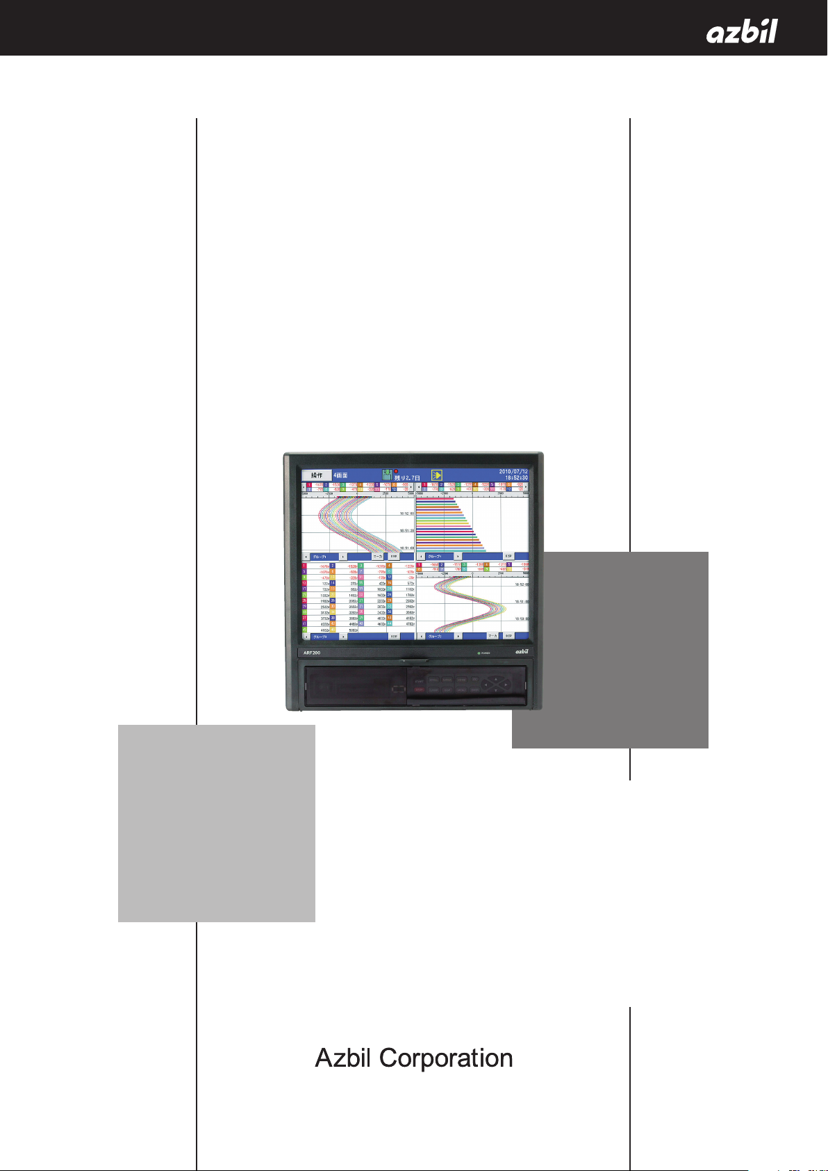
ARF200
Paperless Recorder
Operation Manual
No. CP-UM-5613E
Thank you for purchasing the ARF200
Paperless Recorder.
This manual contains information for
ensuring the correct use of the ARF200
Paperless Recorder. It also provides necessary information for installation, maintenance, and troubleshooting.
This manual should be read by those who
design and maintain equipment that uses
the ARF200 Paperless Recorder. Be sure
to keep this manual nearby for handy
reference.
Page 2

NOTICE
Be sure that the user receives this manual before the product is used.
Copying or duplicating this user’s manual in part or in whole is forbidden.
The information and specifications in this manual are subject to change
without notice.
Considerable effort has been made to ensure that this manual is free from
inaccuracies and omissions. If you should find an error or omission, please
contact the azbil Group.
In no event is Azbil Corporation liable to anyone for any indirect, special or
consequential damages as a result of using this product.
© 2011-2017 Azbil Corporation All Rights Reserved.
Page 3
Conventions Used in This Manual
About Icons
The safety precautions described in this manual are indicated by various icons. Please be sure you read and understand the icons and their meanings described below before reading the rest of the manual.
Safety precautions are intended to ensure the safe and correct use of this product, to prevent injury to the operator
and others, and to prevent damage to property. Be sure to observe these safety precautions.
Warnings are indicated when mishandling this product might result
WARNING
in death or serious injury.
CAUTION
Examples
Cautions are indicated when mishandling this product might result
in minor injury to the user, or only physical damage to the product.
Use caution when handling the product.
The indicated action is prohibited.
Be sure to follow the indicated instructions.
i
Page 4
Safety Precautions
Be sure to turn OFF the power supply before connecting wires to the power or input/output terminals to prevent an electric shock.
To prevent electric shock, connect the protective ground terminal to a ground of less than 100 Ω.
To prevent electric shock, attach the terminal cover after wiring.
Wire the recorder following the instructions in this manual, using the specified type of power leads
and installation methods. Failure to do so might cause electric shock, fire or faulty operation.
Do not disassemble the recorder or touch components inside it. Doing so might cause electric
shock or faulty operation.
If some hazardous condition arises — for example, if there is smoke from the recorder or if there is a
smell of something burning — immediately turn the power off.
WARNING
CAUTION
When disposing of this recorder, treat it appropriately as industrial waste in accordance with local
regulations.
ii
Page 5
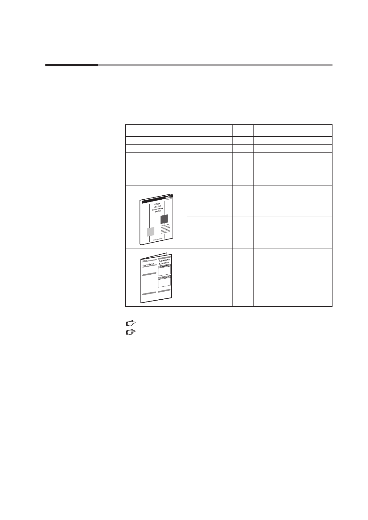
Unpacking
Check the following items when removing the ARF200 from its package:
1. Check the model number to make sure you received the correct product.
2. Check for any obvious damage.
3. Check the contents of the package against the packing list to make sure that all items are included.
Handle the ARF200 and its accessories with care to prevent damage or loss of parts.
If there is some problem with your order, please contact your dealer immediately.
Name Model No. Q’ty Remarks
ARF200 1
Mounting bracket 1
Wrench 1
CF Card ARF910CF0128 (128MB)
Screws (spare) 5 M3.5 X 8 bind
Stylus 1
User’s Manual
CP-UM-5613E 1 This manual
CP-UM-5612E 1 ARF200 Paperless Recorder
Installation and Wiring
CP-UM-5484JE 1 CF Card Instructions
The model No. label is located on the top of the unit.
Chapter 2. PART NAMES AND FUNCTIONS, page 4.
1-2 Model Selection Guide, page 2.
iii
Page 6

Contents
Safety Rrecautions
Unpacking
Chapter 1. OVERVIEW
1.1. Introduction .................................................................... 1
Main Features ................................................................ 1
Additional functions .......................................................... 1
1.2. Model Selection Guide .......................................................... 2
Model number configuration.................................................. 2
Optional parts................................................................ 3
Data analysis software ........................................................ 3
Chapter 2. PART NAMES AND FUNCTIONS
Main unit .................................................................... 4
Rear terminals................................................................ 4
Chapter 3. MOUNTING AND WIRING
3.1. Installation Site ................................................................. 5
3.2. Mounting ...................................................................... 5
Panel cutout dimensions ...................................................... 5
Mounting methods ........................................................... 6
3.3. Wiring Precautions.............................................................. 7
3.4. Terminal Block .................................................................. 8
3.5. Wiring of Power and Protective Ground Terminals................................. 9
3.6. Wiring of Measurement Input Terminals ......................................... 10
3.7. Alarm Output Wiring (for applicable models) .................................... 12
3.8. Digital Input Terminals (for applicable models) ..................................15
3.9. Ethernet Connections .......................................................... 17
Chapter 4. SETUP ...................................................................... 18
Chapter 5. FRONT PANEL
5.1. Parts and Functions ............................................................ 19
5.2. Functions of Keys ..............................................................20
5.3. Character Input ................................................................ 21
5.4. How to Operate the Touch Panel ................................................ 22
5.5. Operations in 4-frame Split Screen Display ...................................... 28
iv
Page 7

Chapter 6. SWITCHING SCREENS .....................................................29
Chapter 7. OPERATION SCREENS
7.1. Common Key Functions ........................................................ 31
7.2. Status Bar Information ......................................................... 35
7.3. Real-time Trend Screen ......................................................... 37
7.4. Bar Graph Screen .............................................................. 38
7.5. Numeric Display Screen ........................................................ 38
7.6. Historical Trend Screen ......................................................... 39
7.7. Dual Trend Screen.............................................................. 41
7.8. Alarm Display Screen........................................................... 41
7.9. Internal Memory Screen ........................................................ 43
7.10. CF Card/USB Memory Screen ................................................... 45
7.11. Marker Screen ................................................................. 46
Chapter 8. INITIAL SETTINGS ......................................................... 47
Chapter 9. MENU STRUCTURE ........................................................ 51
Chapter 10. HOME SCREEN
10.1. Quick Recorder Setup .......................................................... 52
10.2. Specifications Display .......................................................... 54
Chapter 11. MENU SCREEN
11.1. Overview ...................................................................... 55
11.2. Input Settings ................................................................. 59
11.3. Display settings................................................................ 68
11.4. Alarm Settings................................................................. 78
11.5. File Settings Screen ............................................................ 81
11.6. Totalizer Settings .............................................................. 85
11.7. Schedule Settings.............................................................. 87
11.8. Marker Settings................................................................ 88
11.9. Memory Operations............................................................ 89
11.10 Network Settings .............................................................. 91
11.11. System Settings...............................................................101
v
Page 8

Chapter 12. WEB SCREEN
12.1. Remote Monitoring and Configuration .........................................108
Chapter 13. RECORDING TO USB MEMORY
13.1. Overview .....................................................................115
13.2. Connectable Media ...........................................................115
13.3. Method of Use ................................................................115
Chapter 14. CALIBRATION
14.1. Overview .....................................................................116
14.2. Conditions....................................................................116
14.3. Preparation...................................................................116
14.4. Connections ..................................................................117
14.5. Zero and Span Adjustment ....................................................120
Chapter 15. PART REPLACEMENT
15.1. Replacement Intervals ........................................................124
Chapter 16. TROUBLESHOOTING .....................................................125
Chapter 17. DISPOSAL .................................................................127
Chapter 18. SPECIFICATIONS
General specifications ......................................................128
Standards .................................................................128
Input specifications.........................................................129
Recording specifications ....................................................130
Display specifications.......................................................130
Setting and operation specifications.........................................130
Alarm specifications ........................................................131
Measurement range, indication accuracy, and display resolution ..............132
External dimensions ........................................................134
vi
Page 9

1
Chapter 1. OVERVIEW
1.1. Introduction
The ARF200 Paperless Recorder is able to measure temperature and various other industrial process
quantities from 12 through to 24, 36 and 48 channels, and display various data in real time on a
12.1-inch TFT color LCD. This recorder can also store measured data in its internal memory or on a
memory card (CF card or USB memory). Stored data can be loaded into off-the-shelf software like
Excel, and data analysis software especially designed for the ARF200 is also available.
Main Features
・ A variety of screen displays
Real-time trends, bar graphs, data in table format, and combined displays of real-time
trends plus bar graphs, real time trends with numeric values, and real time trends plus
historical trends can be freely selected and monitored in the most suitable display format
for your requirements. Other displays include a summary of past alarm activity and a list
of annotations made with the marker function. In addition, up to 6 channel groups can be
registered, allowing easy switching between them and 4-split screen display.
・ Marker function
Symbols and annotations (up to 30 alphanumeric characters) can be written on trend
screens. Annotations can be written freely, and also up to 50 can be assigned to key
combinations for easy writing. Annotations can be written on stored and replayed trend
screens, too. Adding a symbol only without text is also possible.
・ Various memory functions
Start/stop of data storage can be executed by user-selected conditions like key operation,
alarm occurrence, time, etc. and simultaneous storage to as many as 6 files is available.
In normal operation, data is stored in internal memory and can be saved on a CF memory
card.
・ Analog recorder feeling
Since the trend screen displays data in chart format with scales and “pens,” monitoring
the data has the feel of monitoring an analog recorder.
・ Easy setup
Parameters are set easily and interactively by selecting an item from the menu and then
by opening a window. Fast setup of essential parameters can be done on the Home screen.
・ Consumables not required
Since it is paperless, this recorder does not require the consumables needed by other
recorders, like charts, pens and ink.
・ Easy data management
Older data stored on a CF card can be read and managed using off-the-shelf software like
Excel (a registered trademark of Microsoft Corporation).
・ Availability of software package
Data analysis can be executed conveniently on a PC with a dedicated software package,
ARF Data Analysis Tool, sold separately (ARF990DA0000, for Windows).
Additional functions
Additional functions are as follows:
Alarm outputs: Alarm relay outputs
Contact inputs: Digital (non-voltage contact) inputs
Page 10

2
1.2. Model Selection Guide
Model number configuration
I
II
III
IV V VI
VII
VIII
Basic
model No.
Power
supply
Input
Option 1
Option 2
Option 3
Addition 1
Addition 2
Notes
ARF212
12 inputs
ARF224
24 inputs
ARF236
36 inputs
ARF248
48 inputs
A
100-240Vac, 50/60Hz
S
Standard multi-input (100 ms
specifications)
L
Standard multi-input (1 s
specifications)
0
None
1
12 relay outputs (normally open
contacts)
2
6 relay outputs (normally
closed contacts)
3
24 relay outputs (normally open
contacts)
4
12 relay outputs (normally
closed contacts)
5
12 relay outputs (normally open
contacts) + 6 relay outputs
(normally closed contacts)
A
8 non-voltage contact inputs
B
8 non-voltage contact inputs +
12 relay outputs (normally open
contacts)
C
8 non-voltage contact inputs +
6 relay outputs (normally
closed contacts)
D
8 non-voltage contact inputs +
24 relay outputs (normally open
contacts)
E
8 non-voltage contact inputs +
12 relay outputs (normally
closed contacts)
F
8 non-voltage contact inputs +
12 relay outputs (normally open
contacts) + 6 relay outputs
(normally closed contacts)
0 None
0
None
0 None
D With inspection results
Y With traceability certification
0
None
Page 11

Optional parts
Name Model number Notes
CompactFlash car d ARF910CF0128 128 MB
CompactFlash car d ARF910CF0256 256 MB
CompactFlash car d ARF910CF0512 512 MB
CompactFlash car d ARF910CF1000 1 GB
CompactFlash car d ARF910CF2000 2 GB
PC card adapter AR F910ADP000
Resistor 81401325 250 ± 0.02 % (qty.: 1)
Resistor 81446642-001 250 ± 0.05 % (qty.: 2)
Data analysis software
Name Model number Notes
ARF Data Analysis Tool ARF990DA0000
3
Page 12
4
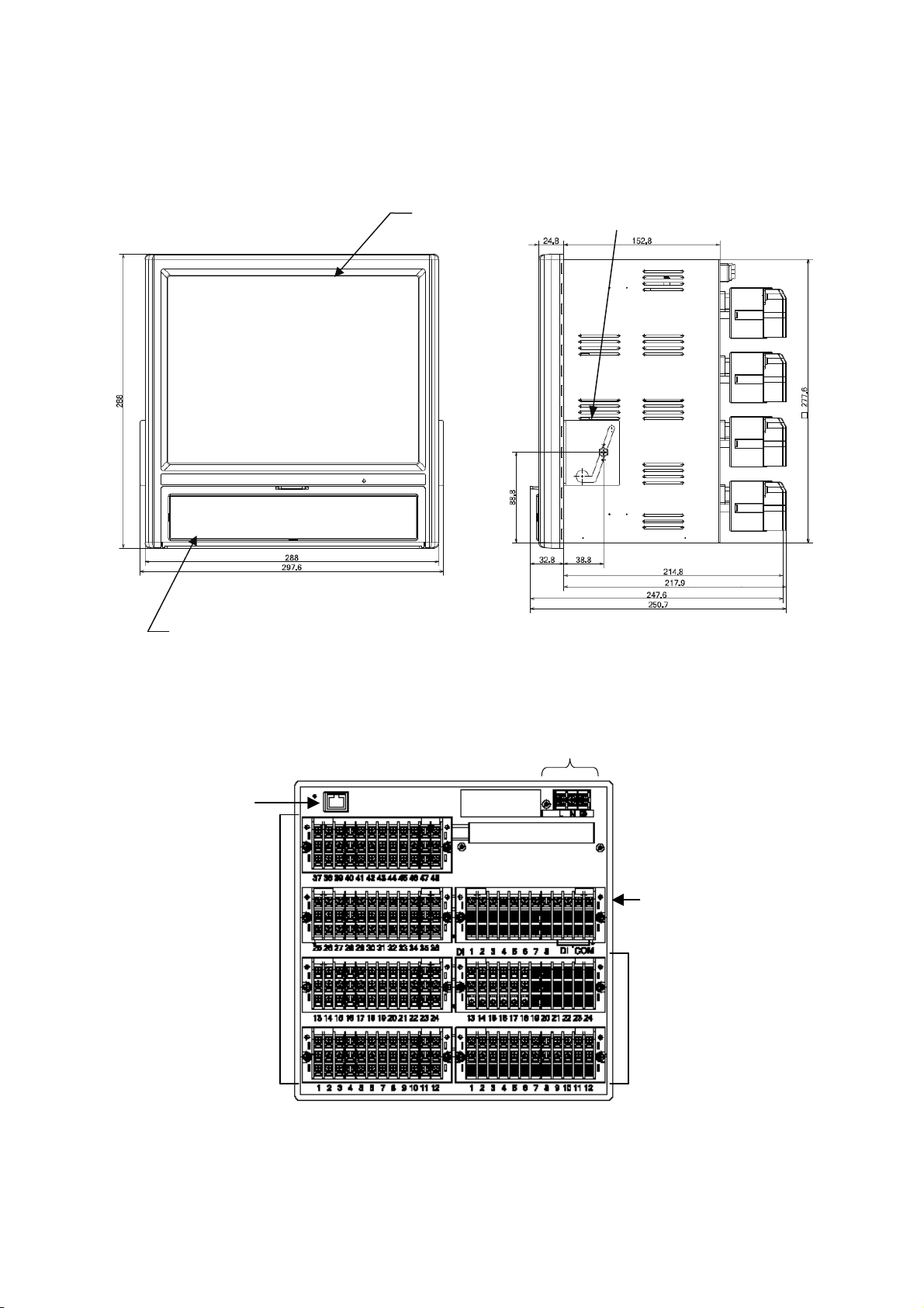
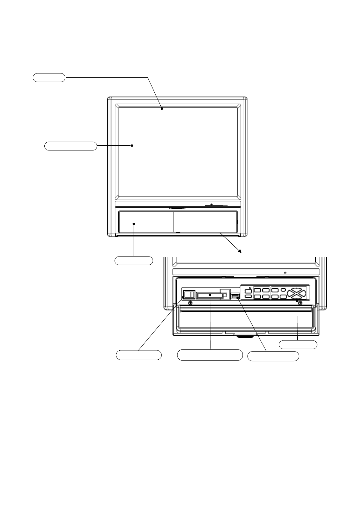
Chapter 2. PART NAMES AND FUNCTIONS
Main unit
(With options attached)
(With options attached)
Key cover (for the functions of keys, see chapter. 5 )
Display
Mounting bracket (2, left + right)
Rear terminals
Power and protective ground terminals
Non-voltage contact input terminals
Measurement input terminals
Alarm relay output terminals
Ethernet connector
Page 13
Chapter 3. MOUNTING AND WIRING
3.1. Installation Site
The ARF200 recorder is designed for indoor use. Install it in a location with the following
char
・ S
・ Free from d
・ Not subject to excessive mechanical vibration and shock
・ Far from the sources of electri
・ Not near flammable liquid or gas
・ Protected from d
・ Where terminals are not near a heat source (to maximize measurement accuracy)
Handling Precautions
・ To prevent temperature rise, do not put in an airtight enclosure.
・ T
3.2. Mounting
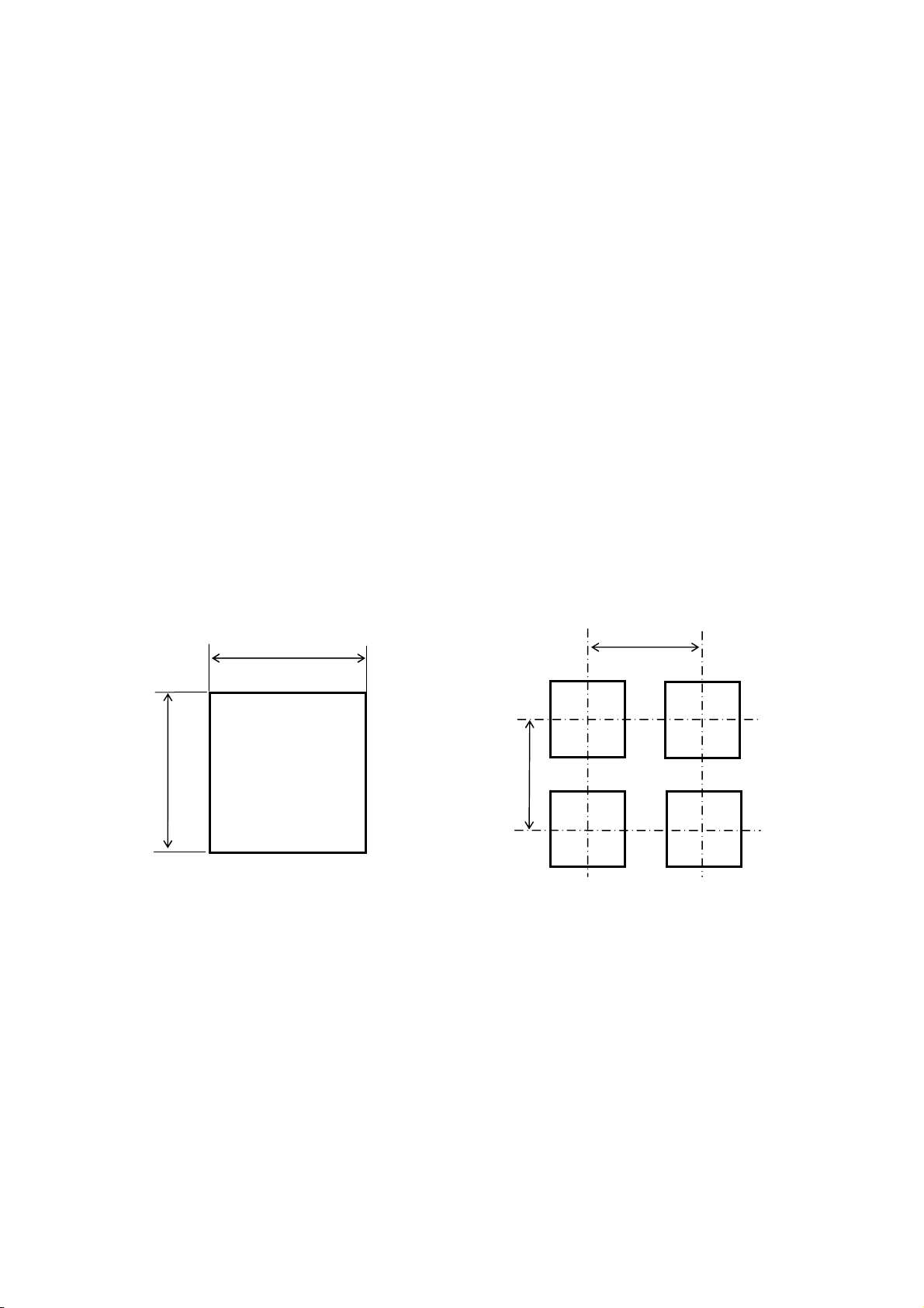
Panel cutout dimensions
stic
+1
-0
281
s:
ust,
smoke, steam, etc.
irect sunlight
パネルカット
281
cal or magnetic fields
+1
-0
Unit: mm
● Minimum interval for gang-mounting
360
360
acteri
teady ambient temperature and humidity of about 23 °C, 50 % RH
o prevent deformation of the front panel, do not expose to hot air exhaust (50 °C or more).
5
Page 14
6
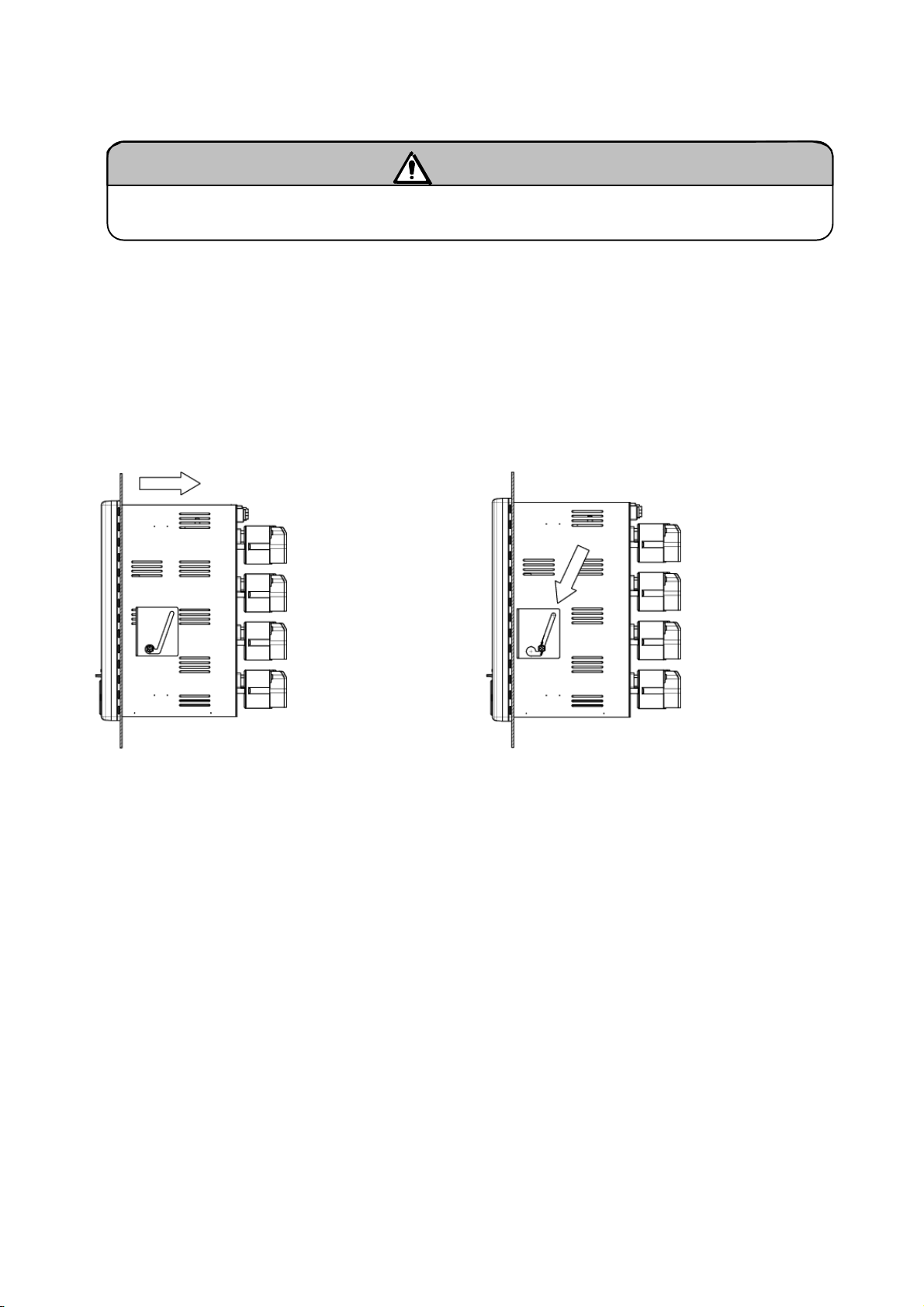
Mounting methods
(1) Insert the ARF200 into the panel cutout on the instrument panel.
(2) There are two screw holes, one on the left side and one on the right side of the ARF200. Lightly screw
in the 2 screws provided.
(3) Next, put the hexagon head of the screws inserted above into the round holes of the mounting brackets,
and firmly press the ARF200 against the instrument panel (from the front) while sliding as shown in the
figure. In this state, tighten the mounting screws with the provided wrench or Phillips screwdriver.
Note that the left and right mounting brackets are different. (Installation should be done by two
people.)
Handling Precautions
・
The recommended tightening torque is 1.0 N・m. Tightening the mounting bracket screws to a higher
torque might deform or damage the case.
・ In mounting, the top surface should not be tilted down toward the back more than 20°, and it should
not be tilted up at all. Do not tilt toward the right or left sides.
・ Mount on a panel made of steel plate 2 to 6 mm thick or a panel having equivalent strength.
Slide
• For mounting the recorder on the panel, be careful of injury by dropping it.
Warning
Page 15
3.3. Wiring Precautions
・
Be sure to turn OFF the power supply before connecting wires to the power or input/output
terminals to prevent an elect r ic shock.
・ Attach crimp terminals to the ends of wires to prevent looseness or disconnection of terminals
and short-circuit between terminals. Use the crimp terminals with an insulating sleeve to prevent
electric shock.
・ Arrange and secure connected wires so that a passing person or object cannot easily be caught
on them. Otherwise disconnection, electric shock, or other problems may occur.
・ To prevent electric shock, connect the protective ground terminal to a ground of less than 100
.
・ To prevent electric shock, attach the terminal cover after wiring.
Handling Precautions
・ Use a single-phase power supply having a stable voltage without any waveform distortion to prevent
malfunction.
・ Do not place the input/output wires close to, or in parallel with, power lines or high-voltage circuits. If
run parallel to each other, keep the I/O wires 50 cm or more apart.
they
・ For thermocouple (TC) inputs, keep the input terminals away f rom a heat source (a heating body) to
reduce a refere
nce junction compensation error. Don’t expose the input terminals to direct sunlight,
etc.
・ Don’t use any unused terminals for relaying; otherwise the electr ic circuits may be damaged.
・ To prevent malfunction, keep all connected wires as far from sources of electrical noise as possible.
Use a counter
measure (see below) if wires are unavoidably close to a noise source.
Warning
Electromagnetic switch, etc.
Major noise sources Power line with waveform distortion
Inverter
Thyristor regulator
Counter-measure
Insert noise filters between power terminals and input/output terminals.
A CR f ilt er is often used.
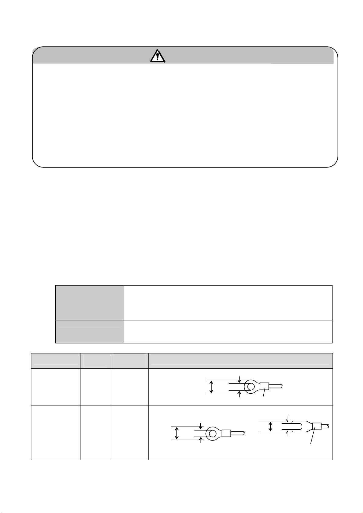
Terminal type and crimp terminal dimensions
Terminal
Power and
protectiv
e
ground
Screw
size
M4
Tightening
torque
Round type
1.2N・m
terminals
Round type
Other
terminals
M3.5
0.8N・m
8 or less
Note: Use the round type if possible.
Crimp terminal dimensions (unit: mm)
8.5 or less
Thickness: 0.8
3.7 or more
4.3 or more
With an insulating sleeve
Fork type
8 or less
With an insulating sleeve
With an insulating sleeve
Thickness: 0.8
Thickness: 0.8
3.7 or more
7
Page 16
r
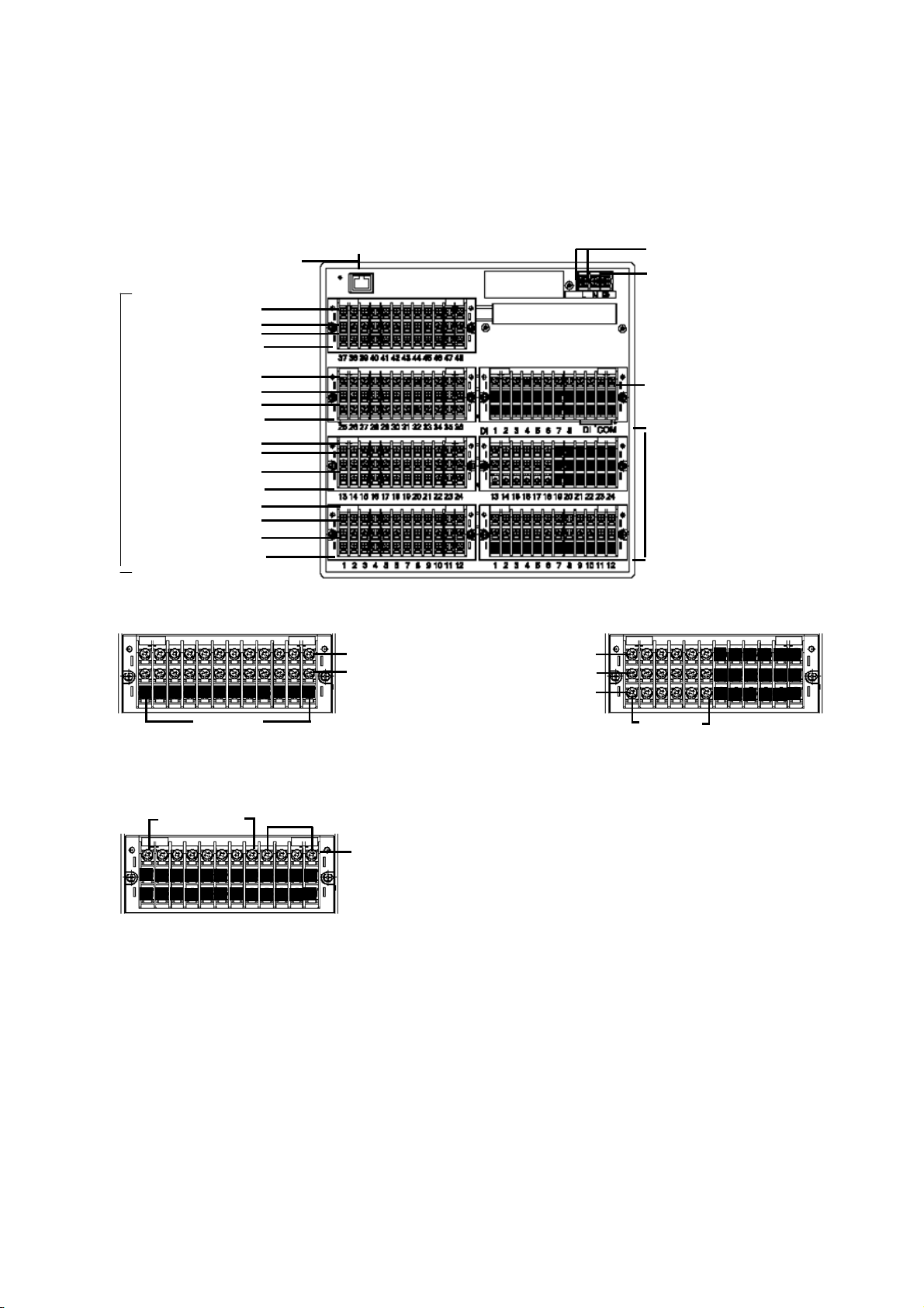
3.4. Terminal Block
The following figure shows the terminal block as configured for options (alarm relay outputs [12
Form A contacts, 6 Form C contacts] and 8 contact inputs). The Ethernet connector is the standard
type.
TC, mV(+), RTD (A) terminals
TC, mV(-), RTD (B) terminals
Measurement input terminal blocks
TC, mV(+), RTD (A) terminals
TC, mV(-), RTD (B) terminals
TC, mV(+), RTD (A) terminals
TC, mV(-), RTD (B) terminals
TC, mV(+), RTD (A) terminals
TC, mV( -), RTD ( B) t er min als
[Option terminal blocks (* Subject to change)]
• Alarm relay ou tputs ( 12 no rmall y open contact s)
• 8 non-voltage contact inputs
Ethernet connecto
RTD (B) terminals
[CH37-48]
RTD (B) terminals
[CH25-36]
RTD (B) terminals
[CH13-24]
RTD (B) terminals
[CH1-12]
Terminal
Nos.1-12
Terminal Nos.1- 8
COM terminals
N.O. terminals
COM terminals
Non-voltage contacts inputs
• Alarm relay outputs (6 normally closed contacts)
N.C. terminals
COM terminals
N.O. terminals
Power terminals
Protective ground terminals
Non-voltage contact inpu ts (optio n)
• 8 non-voltage contact inputs (common)
Alarm relay outputs ( 2 opt ions)
• 12 N.O. contact terminal block
• 6 N.C. contact te rmin al bloc k
* ARF2 _ _ _ _ 5 _ _ _ _,
ARF2 _ _ _ _ F _ _ _ _
• Upper: Terminal block for N.O. output
• Lower: Terminal block f or N .C. ou tput
Terminal
Nos.1 -6
8
Page 17
Note: The input, alarm, and contact input terminal blocks can be removed to facilitate wiring. Because
the terminal block is connected by connectors, it can be removed easily by loosening two
screws.
Terminal block
Moun
ting screws
Handling Precautions
・ The thermocouple input terminal block cannot be repositioned or replaced wi th a terminal block for
another instrument. Measure ment error w i ll occur.
・ Before mounting or dismounting a terminal block, turn off the external power switch to prevent the
rical circuits fro m be i ng damaged.
elect
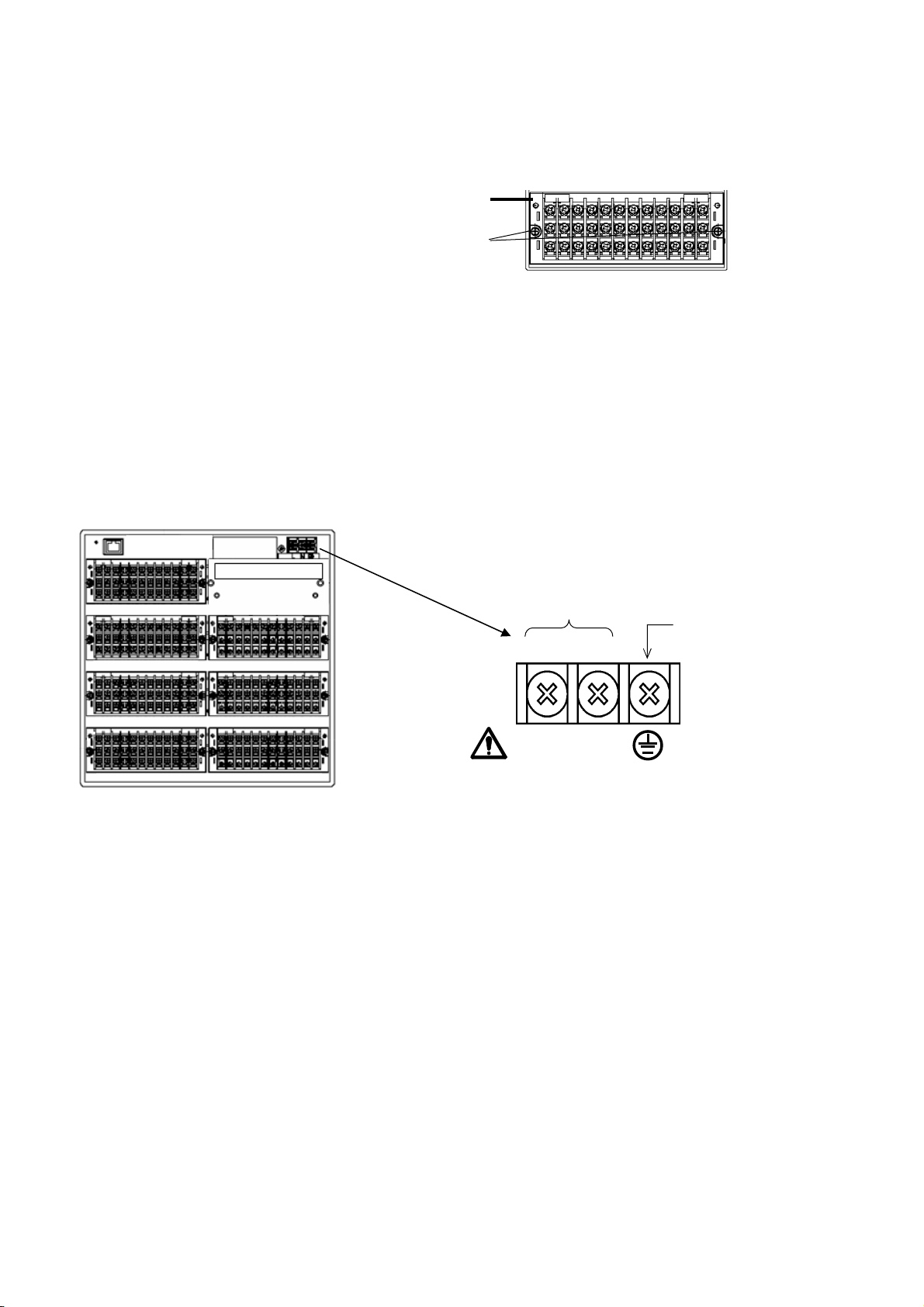
3.5. Wiring of Power and Protective Ground Terminals
(1) Power and protective ground terminals
Power terminals
L
100-240VAC 50/60Hz 65VA MAX
N
(2) Connection of power terminals
For connection to the power terminals, use a 600 V PVC-insulated cable terminated by crimp
terminals with insulating sleeve.
Note: Use a cable conforming t o t he standards below.
IEC 227-3
ANSI/UL817
CSA C22.2 No. 21 and No. 49
Protective
ground
terminal
(3) Connection of protective ground terminal
Be sure to connect this terminal to the protective ground of the power supply facility. For this
connection, use a cable terminated by a crimp terminal with an insulating sleeve.
• Ground wire: copper, 2 mm
2
or more in cross-sectional area (green/yellow)
Handling Precautions
・ To prevent electric shock, attach the terminal cover after wiring.
9
Page 18
A
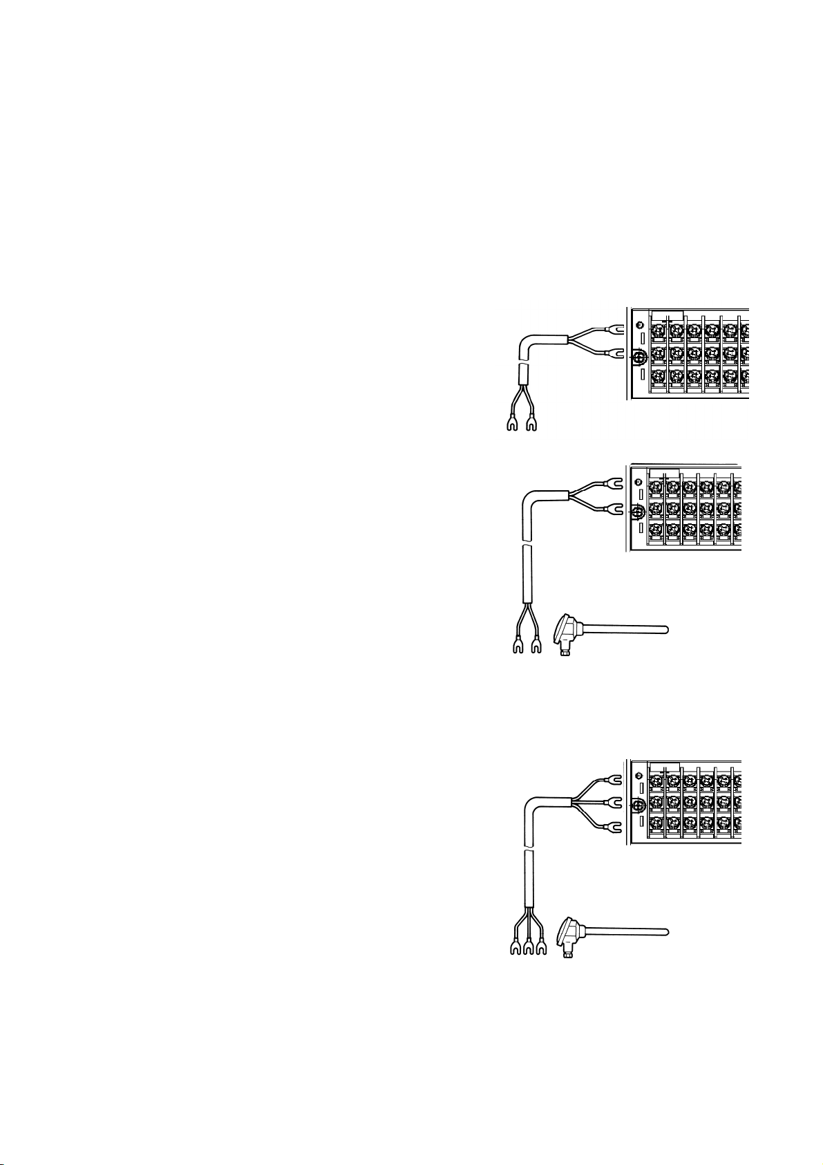
3.6. Wiring of Measurement Input Terminals
(1) Allowable input voltage
•Thermocouple input (burnout disabled), DC voltage input (±2 V max.): ± 10 Vdc max.
•DC voltage input (±5 to ±50 V): ±60 V max.
•Thermocouple input (burnout enabled), resistance thermometer (RTD) input: ±6 Vdc max.
Handling Precautions
•Use crimp terminals with insulating sleeves on the end of wires connected to the inp ut terminals.
(2) DC voltage (or current) input
For input, use twisted cable made for instrumentation
use, in order to suppress noise. For current input,
connect a shunt resistor between the current input
terminals of that channel before wiring.
(3) Thermocouple (TC) input
Be sure to use thermocouple wire (or compensating leads)
to the input terminals of this recorder. If copper wire is
used part of the way, a significant measuring error will
occur. Avoid connecting a pair of thermocouple wires to
another device (controller, etc.) in parallel because such a
connection may affect the measurement of each device. If a
parallel connection is unavoidable, check whether the
effects are within the allowable range under the following
conditions:
•Set the burnout to disabled.
•Ground the device that you wish to connect in parallel at one point. In addition, install the device near the ARF200 and if possible
use t
he same power supply.
•Do not shut off the power of either device during operation.
DC voltage
input
Twisted cable
for
instrumentation
Compensating
wire
(+)
(-)
Red (+)
White (-)
Thermocouple
(4) Resistance thermometer (RTD) input
Use a 3-core cable in which each lead has equal resistance.
Also, do not connect a single RTD in parallel with more
than one recorder (controller, etc.).
3-core cable, each wire having the
same diameter, same length, and
same resistance (each less than
10 ).
B
C
Resistance thermometer
Handling Precautions
・ The allowable amount of noise on the measurement input terminals is 30 Vac (or 60 Vdc) or less.
Because of common mode noise and t he l ike, take care that the allowable noise level is not exceede d.
After wiring, attach the terminal cover to prevent electric shock and protect the input wires. Also, the
terminal cover can reduce the reference j unction compensation error for thermocouple input.
Channels are isolated from each other. Note, however, that the C terminals for RTDs are
・
short-circuited on the AR F _ _ _ AS (100 ms input cycle models) between channels 1 & 4, 5 & 8, and 9
1 2 3 4 5 6
1 2 3 4 5 6
1 2 3 4 5 6
10
Page 19

&12 in each input terminal block, and on the ARF _ _ _ AL (1 s input cycle models) the C terminals are
short-circuited between a l l channels in each input terminal block.
11
Page 20
A
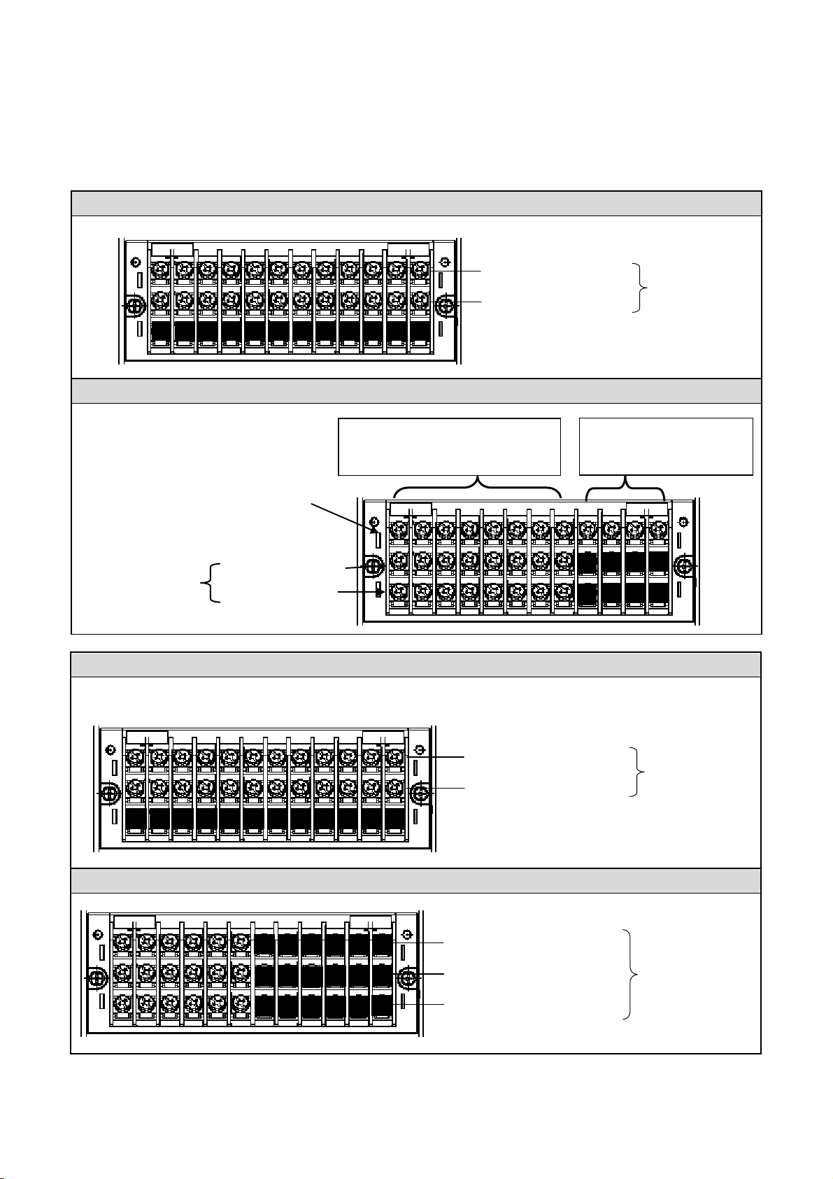
3.7. Alarm Output Wiring (for applicable models)
(1) Alarm output terminal layout
The terminal arrangement depends upon the type of alarm output.
Alarm relay output (1a)
MOS alarm relay
outputs (8)
Digital inputs (8)
COM terminals (M3.5)
. te
N.O rminals (M3.5)
N.O. terminals (M3.5)
COM terminals (M3.5)
MOS alarm relay output (1a)
(From left) DI1, DI2, . . . –DI8
Digital inputs (8)
Alarm relay output (1a)
Alarm relay
outputs (12)
Digital input (DI) COM
(4 comm
on inputs)
1 2 3 4 5 6 7
N.O. terminals (M3.5)
COM te
Alarm relay output (1c)
N.C. terminals (M3.5)
COM terminals (M3.5)
N.O. terminals (M3.5)
rminals (M3.5)
Alarm relay
outputs (12)
larm relay
outputs (6)
12
Page 21
y
r
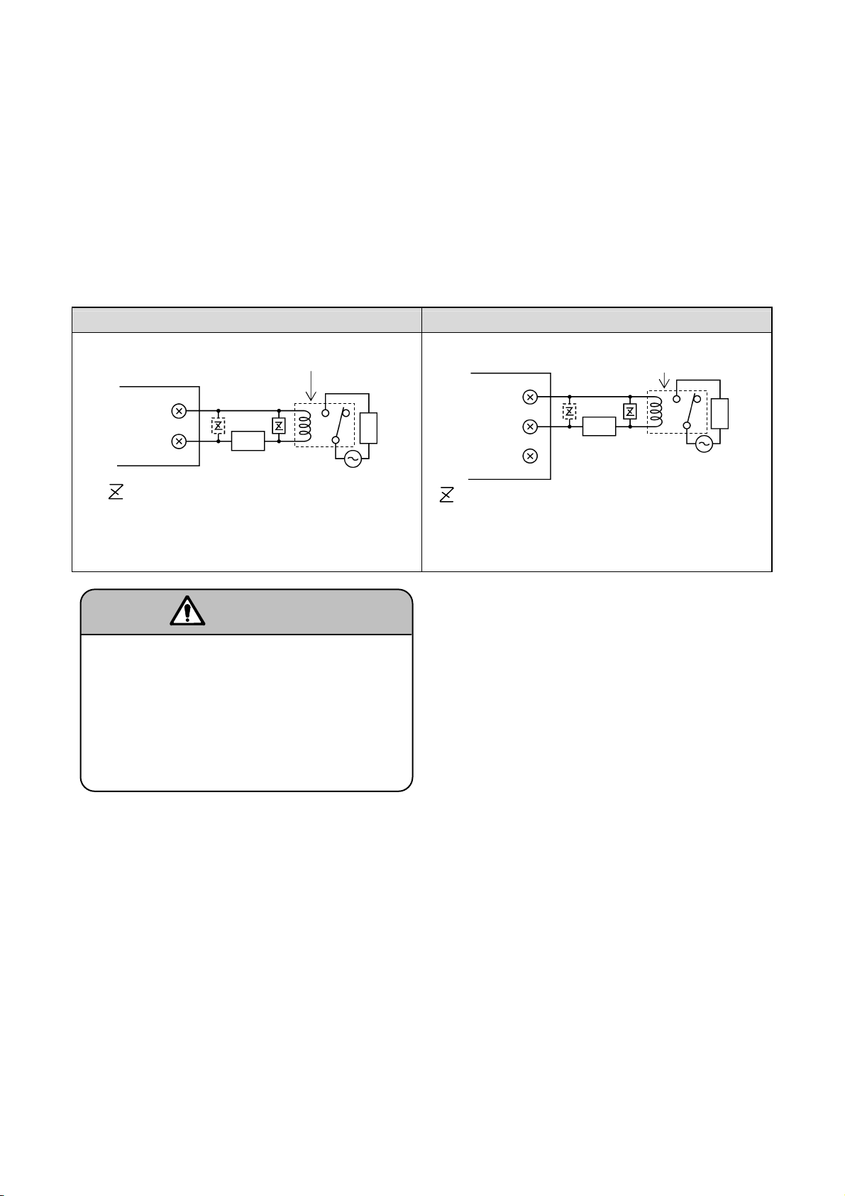
(2) Wiring
Turn off the power supply and buffer relay power supply before wiring to prevent electric shock.
Connect leads to the load via a buffer relay.
Use leads with crimp terminal lugs (with insulating sleeves).
If a voltage of 30 V
ac/60 Vdc or more is applied to the output terminals, connect the
signal lead by a cable terminated by a round crimp terminal lug (with insulating sleeve).
Also, use double insulation (2300 Vac withstand voltage or more) for signal leads to
which a voltage of 30 Vac/60 Vdc or more is applied, and basic insulation (1390 Vac
withstand voltage or more) for other signal leads. After wiring, be sure to attach the
terminal cover to prevent electric shock.
Example of mechanical re lay Form A contact output Example of mechanical re lay Form C contact output
Buffer relay
ARF200
Buffer rela
ARF200
Power
a
Load
Load
COM
: Contact point protective surge absorber
(placement on the “a” side is recommended)
Powe
N.O
COM
N.
C
*
: Contact point protective surge absorber
(placement on the “a” side is recommended)
* The operation of N.C. terminals is opposite to that of
. terminals. They open when an alarm occur s.
N.O
b
Connect a load that is with in t he specified
contact capacity of the alarm output terminals.
Since the power for the buffer re lay is applied
to the alarm output terminals, touching these
terminals will r e sult in an electric shock. Be
sure to attach the terminal cover after wiring.
Warning
Handling Precautions
・ The alarm output device can be damaged by a spark from the buffer relay or breakdown of the surge
absorbing element. Be sure t o take appropriate safety measures as necessary.
13
Page 22

(3) Specifications for wiring
Item Description
Contact rating of mechanical relay
outputs (both Form A and Form C
contacts)
Selection of buffer relay
Selection of surge absorber and
mounting
•
Power supply Resistive load Inductive load
100 Vac 0.5 A 0.2 A
240 Vac 0.2 A 0.1 A
30 Vdc 0.3 A 0.1 A
• Coil rating: less than the contact rating of the output terminals
• Contact rating: more than twice the load current
Minimum load: 100 A
and 100 mVdc
A relay wi th a built-in coi l surge absorption element is recommen ded. Add an
additional buffer relay if the buffer relay does not satisfy the load rating.
• Use an appropriate surge absorber element to protect the contacts if the
buffer relay does not already have one .
• The MOS relay might burn out if a signal exceeding the contact rating is
applied, even momentarily .
• To prevent malfunction caused by a li ght load, the most effective mounting
position for the surge absorber is on the coil si de of the buffer relay (‘a’ in the
wiring diagram in section 3.7, (2)).
• The surge absorber is generally composed of a capacitor (C) and resistor
(R).
Refer ence values for C and R
C: 0.01 F (rating about 1 kV)
R: 100 to 150 (rating about 1 W)
Azbil Corporation’s surge absorber is No. 81446365 -001 (qty. 10).
Handling Precautions
The common terminal of each alarm output is separate from the others.
14
Page 23
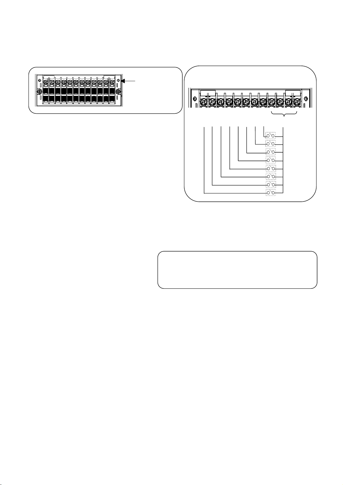
・ 3.8. Digital Input Terminals (for applicable models)
(
1) Digital input terminals
Contact input terminals
(2) Wiring
Turn off the power before wir ing to prevent an electric shock.
Use a non-voltage contact signal for digital input terminals.
Use crimp terminals with insulating sleeves on the end of
wires connected to the digital input terminals.
Digital input specifications
Volt age with contact s open: Approx. 5 V
Current when contacts close: Approx. 4 mA short-circu it)
■ Connection example
DI 1 2 3 4 5 6 7 8 COM
15
Page 24

Handling Precautions
・ Relays and switches connected to the contact input terminals should be designed for low voltage/current
load use.
■ DI terminal functions
(1) Digital input Detects ON/OFF (closed/open) state. Set the range type to DI.
(2) Pulse input For pulse input, set the range type to either Pulse (+) or Pulse (-).
(Se
(3) Integration rese t Resets the cum ulative count. When the specified digital input te rminal is energized, the
(See 11.
(4) Marker Writ
(See 11.
(5) File write Starts/stops recording of data in an internal memory file. Recording starts when the digital
(Se
(6) Time correction Adjusts the time when the digital input terminal turns ON.
(See 11.1
S
ee 11.2, “Input Settings.”)
(
e 11.2, “Input Settings.”)
cou
nt is reset.
6, “Totalizer settings.”)
es annotations. Annotations can be written on trends while the digital input terminal is
ON.
8, “Marker settings.”)
inp
ut terminal turns ON.
e 11.5, “File Settings Screen.”)
1, “System Settings.”)
16
Page 25
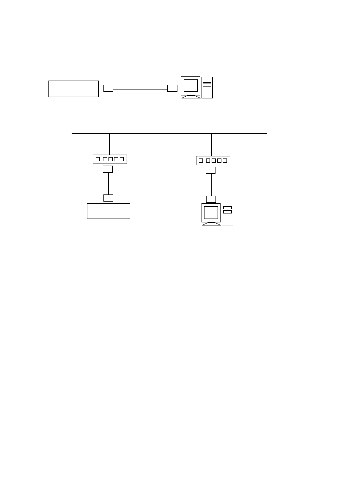
3.9. Ethernet Connections
1-to-1 c onne ction with a PC
T o connect the PC and the ARF200 in a 1-to-1 connection, use a crossover cable or a hub.
ARF200
N-to-N connections with PCs
When connecting to multiple PCs or to an existing LAN, use a hub and straight cables between the hub
and ARF or PC units.
ARF200
Crossover cable
PC
(With LAN function)
LAN
Hub Hub
Str aight cable
Str aight cable
PC
(With LAN function)
17
Page 26
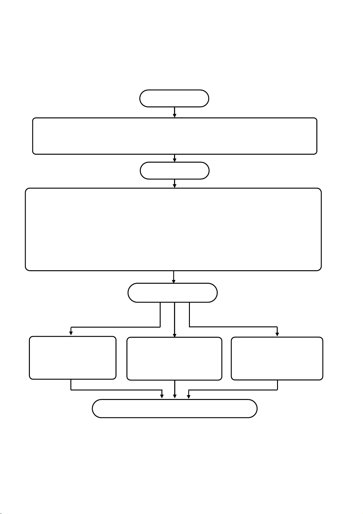
Chapter 4. SETUP
Start
,
,
The ARF200 is shipped with default factory settings. For actual operation, however, be sure to do
the following setup procedures.
Preparations for operation
Mount the ARF200 in a panel and wire it properly .
PowerON
The A R F200 is shipped with default settings, but be sure to change the following settings as
appropriate for the actual application environment and measurement objective.
1. Initial settings (Chapter 8, INITIAL SETTINGS)
2. Settings for input processing, display, and recording, which can be changed either all at once or
separately.
All settings at once: HO ME SCREEN (10.1, Quick Recorder Setup)
Individual settings: MENU SCREEN (11.2, Input Settings; 11.3, Display Settings; 11.5, File
Settings Screen)
Operation
Setting
Screen switching
Chapter 6
St art/stop recording
11.5
File settings screen
Saving to a memory
card
Stop and Power OFF
Note)
On portions of the LCD screen, some pixels may be always lit or always not lit, and there may be
unevenness in brightness due to t he characteristics of the liquid crystals, but these are not malfunctions.
18
Page 27
Chapter 5. FRONT PANEL
5.1. Parts and Functions
Display
12.1-inch TFT color LCD.
For operation screens,
see Chapter 7.
Touch panel
View with key cover open.
Key cover
Keyboard
Power switch
CF card drive
USB connector
Handling Precautions
・ The front panel is ma de of glass. To avoid injuries due to broken glass, protect it from impact.
19
Page 28
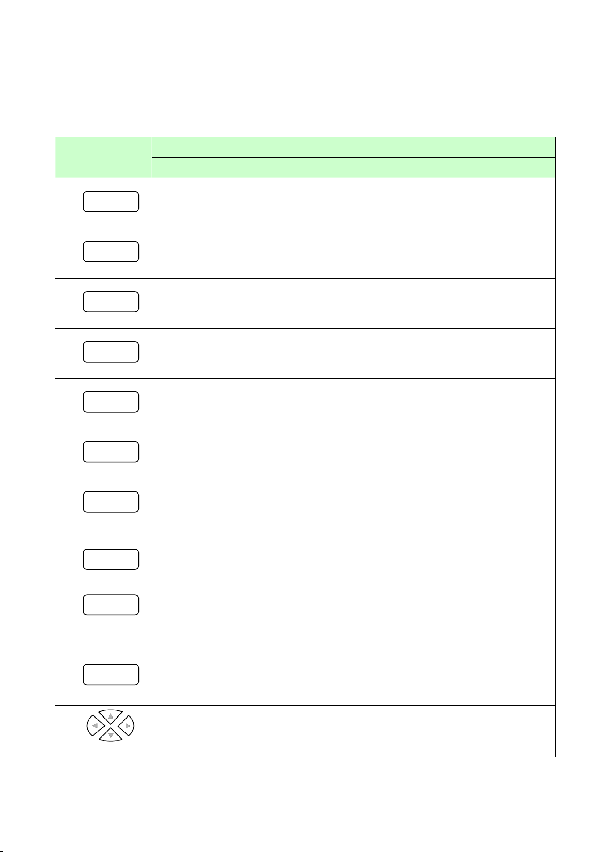
5.2. Functions of Keys
The usage and functions of the keys is different depending on whether an operation screen or a
settings screen is displayed. All key operations can also be done on the touch panel, so all operations
are possible with the key cover closed.
Key
START
Starts recording Not used
STOP
Stops recording Not used
SCROLL
Switches the scroll mode on and off, or
moves to the historical trend screen
CURSOR
On the historical trend screen, switches
the cursor mode on and off.
MARKER
Writes an annot ation on the trend
screen
DISP
Displays the DISP menu
Main Functions
Operation screen Settings screen
Not used
Invalid
Not used
Takes a snapshot when pressed and
held
HOME
MENU
Displays the HOM E screen Quits the Home scr een
Displays the MENU screen or returns
from MENU screen to previous screen
Returns to the previous sc r een
ESC
ENTER
Cancels a menu or returns to the
previous screen
Confirms a menu item selection or
displays a menu (the “ENTER menu”)
with varying contents, depending on the
screen.
Returns to the operation screen or to t he
previous screen
Opens the selected menu or ent ers the
numeric value, character, etc. selected
by the cursor. Also, returns to the
operation screen, or stores a para met er.
Arrow keys
These keys select (highlight) a menu
item or change the display group or
channel number.
Arrows move the cursor left, right, up
and down.
20
Page 29
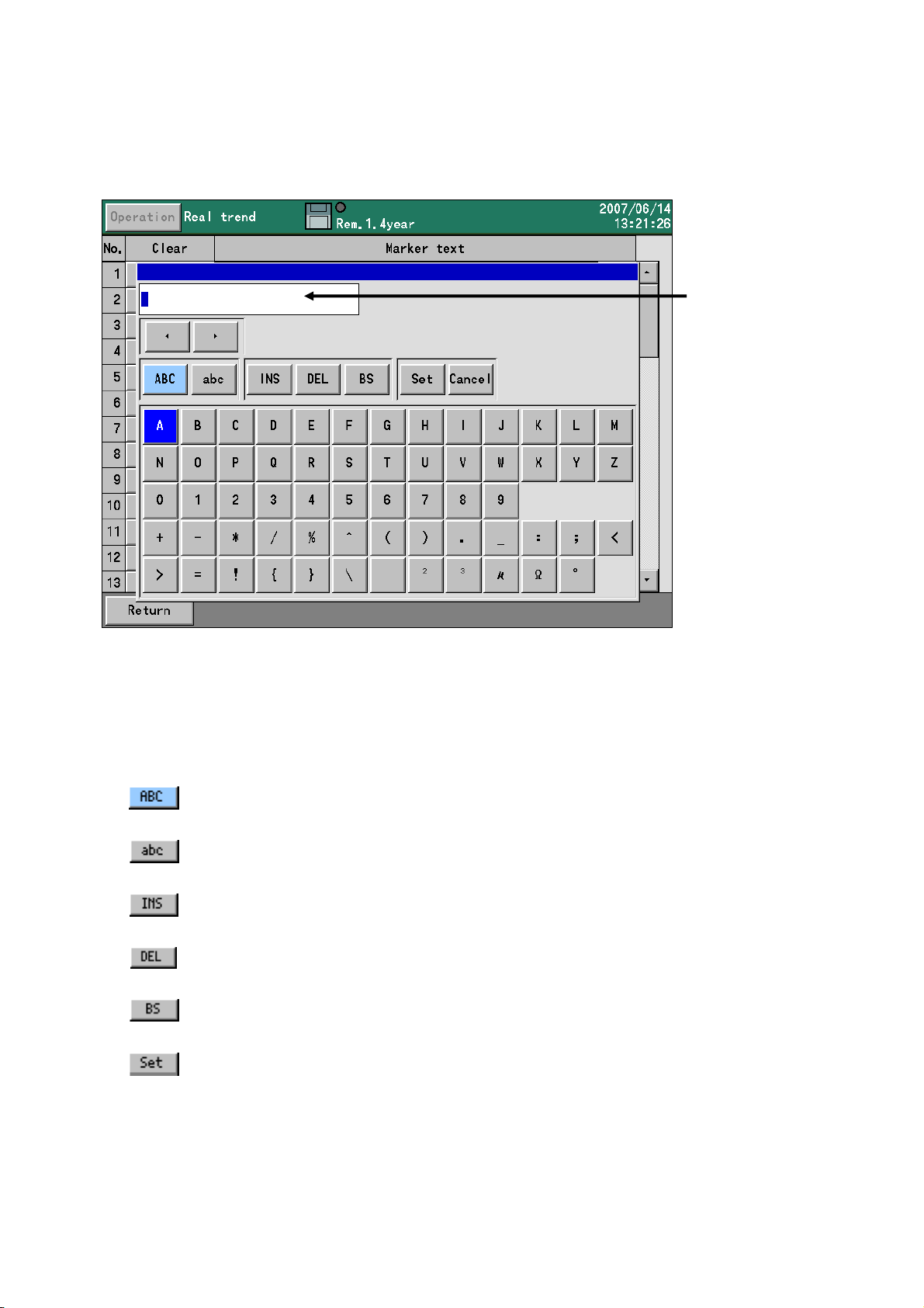
5.3. Character Input
The character input screen seen below is used for setting or entering tags (labels for the channels),
annotations using the marker function, and passwords. Pressing ENTER from a relevant screen displays
the character input screen.
On the character input screen, after moving the focus (indicated in blue) to uppercase letters or
lowercase letters, pushing the down arrow key moves the focus to the row of letters below. Then,
use the arrow keys to move the focus to the desired character, and press the [ENTER] key. The
selected character is then displayed in the character input space.
When selected, uppercase letters, symbols and numerals can be entered.
When selected, lowercase letters, symbols and numerals can be entered.
Insert key. Toggles character input between insert mode and overwrite mode.
Delete key. Deletes the character selected in the character input space.
Backspace key. Deletes the character before the cursor position.
Accepts the string of characters input in the character input space. The
same result can be obtained by pressing the [ENTER] key when the input
Character input space
21
Page 30
5.4 How to Operate the Touch Panel
(
)
All ARF200 operations can be done on the touch panel. If the touch panel is not operating normally or if the same
operation method as on the ARF100 series is preferred, the keyboard can be used.
The ARF200 can be operated intuitively with the touch panel. The following describes basic screen operation
methods. For details on each individual screen, see the descriptions in Chapter 7, OPERATION SCREENS.
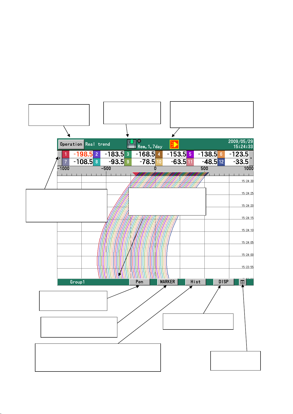
5.4.1 Touch Operations on the Operation Screen
[Operation] button
Displays the operation
menu.
Disk icon
Touching this icon
starts/stops recording.
Channel selection button
This is displayed when all
registered channels cannot be
displayed. Clicking this button
selects the display channels.
Handwritten input on trend s
is possible. (See 5.4.3.)
[Pen] button
[Marker] button
Writes markers on trends. (See
7.3 and 7.6.)
Displays historical trends. While a historical trend is
displayed, [Real] is displayed, and when a trend is
opened from a file list, etc., [Back] is displayed.
[Hist] button
Touching this icon when an alarm
is generated acknowledges the
alarm.
Group selection button
This is displa yed when th ere ar e
multiple groups in use. Clicking
this button selects the group.
[DISP] button
Displays the DISP menu.
Alarm icon
See 7.2.
[Split] button
Displays the screen
split into 4 sections.
22
Page 31

<[Operation] menu>
Menu Item Description
Start recording Starts recording. Same as the START key
Stop recording Stops recording. Same as the STOP key
HOME setting Opens the HOME settings. Same as the HOME key
MENU setting Opens the MENU settings. Same as the MENU key
<[DISP] menu>
Menu Item Description
Select display Changes the operation screen type.
Select group Changes the display group.
Automatic switching Turns automatic switching of groups and channels ON/OFF. A
checkmark indicates that this item is ON. It is disabled when "0" is
set for the automatic selection time.
Snapshot Saves a hard copy of the screen to the CF card (SNAPSHOT)
folder.
Pause Stops screen refreshing except for the status bar. Press any k ey to
resume. During a pause, compilation, recording, and all other
processing except drawing is executed. Also, a snapshot can be
taken during a pause by clicking the DISP key.
Display off Turns the LCD display off. Press any key to turn the display on
again.
4-frame split screen Displays the screen split into four sections.
Expansion/
compression
<Touch operation in a 4-frame split scre en display>
The display type and group can be selected in each frame by touching the DISP button. For details see
5.5. Also, operations on each fra m e can be executed by clicking the group selection button and marker
button for the frame.
Trends can be displayed with the time axis compressed (same size
to 1/60).
23
Page 32

5.4.2 Touch Operations in Setting Screens
On the MENU and HOME set t ings screens, settings can be changed most easily by touch. To enter a
value for any item, touch the but t on w it h t he ▼ ma r k .
To return to the previous screen, click the [Bac k] but ton.
On screens with a scroll bar, information can be scrolled by touching and moving the scrol l bar. Als o,
screens can be scrolled one at a t ime by touching above or below the scroll knob.
Note
• Do not rub or press a knife or other sharp object on the touch panel.
• Avoid storage or use in atmospheres subject to water, organic solvents and acid, or where the touch panel
• Avoid use in locations exposed to direct sunlight.
• Wipe off dirt from the touch panel using a soft, dry cloth or a cloth moistened with a neutral detergent or
Cautions When Us ing the Touch Panel
may come into contact these liquids.
alcohol. If chemicals come into contact with the touch panel, wipe off immediately.
• Condensation is a natural phenomenon and can occur inside the touch panel. If the touch
panel is brought close to room temperature, condensation will disappear naturally. However,
use of the touch panel with condensation inside should be avoided, since it can cause a
malfunction.
Scroll button
Scroll knob
Scroll bar
24
Page 33

5.4.3 Handwritten Input on Trend Screens
On the real trend screen and historical trend screen, handwritten notations can be freely made by
touching the display and d rawing your finger along it.
To write with your finger, touch
When handwritten in put is enabled,
If [Pen] is touched again, drawn details are fixed and saved, handwritten in put is turned off, and from then
on regular touch operation is possible. Drawn content that was saved can be read again into internal
memory, CD card and USB memory. (See "7.10 CF Card/USB Memory Screen.")
(Delete operation)
Toggles handwritten
input on/off.
once to enable the function.
is displayed in yellow as shown below.
Handwritten input
example
Sets line thickness
and color.
Erases drawn
content.
If
If the drawn content is con t inuous, all of it will be deleted in a single operation. However, if it is not
continuous, only the previ ously drawn locus will be deleted. Further touches of the but t on will delete loci in
the order of input, starting fro m the most recent locus.
Note: Once content is saved by touching the [Pen] button, it cannot be deleted with [ Undo].
is touched while writing on the touch screen, the previously draw n cont ent is deleted.
25
Page 34

(Setting operation)
The thickness and color of handw rit t en input can be be changed by touching
10 line thicknes ses
are available.
16 line colors are
available.
Supplementary Explanation
The number of handwritten points is obtained by periodically sensing and sampling coordinate
data when the touch panel is touched. T he m aximum number of points that can b e input is 8,000.
When the number of drawn points exceeds this limit, the oldest points are erased.
It is difficult to dist inguish v isually how m any points ha ve been inp ut. However, since the num ber
of points is sam pled peri odicall y, writing slowly with the pen will res ult in m ore p oints being used;
and alternativel y, writing quickly will result in fewer poin ts being use d.
The thickness of the loc us, and the size and color of the font bear no relation to the num ber of
points consumed.
The reference figure below shows the number of handwritten points recognized by internal
processing on the recorder.
Number of Handwritten Points
3 points used for
1 touch
.
← Fine Thick →
Example of use
Quickly drawn:
approx. 8
points used
Slowly drawn:
approx. 80
points used
26
Page 35

5.4.4 Automatic Scrolling on the Historical Trend Screen
Section 5.4.2 dealt with touch operations on screens with a scroll bar. On the historical trend screen
(see 7.6, “Historical Trend Screen”) and the dual trend screen (7.7, “Dual Trend Screen”), on which
recorded data can be played back , the scroll bar can be made to move automatically by swiping the
screen as if to move it to see the latest part of the graph.
In response to this, the trend screen moves automatically, and automatic scrolling continues until the
screen is touched again. The same operation is possible on historical trends read from either internal
memory or external memory.
Automatic scrolling is possible also while the cursor is display ed. The cursor position tracks as required.
1. Swipe
2. Bar flows
automatically.
27
Page 36

5.5 Operations in 4-Frame Split Screen Display
The screen of the recorder can be split into four sections for displaying inf ormation simultaneously on
four separate screens. However, on a split screen display, the selectable display type is limited. Only
trend time charts, numeric displays and bar graphs c an be selected.
<How to switch from 1-screen display to 4-frame split displ ay>
• Select "4 scre ens" from the DISP menu.
• Touch the
4-frame split screen display can be selected by either of the above methods.
<How to switch from 4-frame s pl it screen display to 1-screen display>
• Touch inside the frame to be expanded.
• Touch the DISP button of the frame to be exp anded, and select "1 screen."
• Click the DISP key to set to the frame selection mode*, click the direction key to select the frame
to expand, and clic k the E NT ER key.
1-screen display can be sele ct ed by any of the above methods.
(*Frame selection mode)
In the 4-frame split screen display, the frame selection mode is entered by clicking the DISP key. In this
mode, the selected frame can be moved using the direction keys, and the following key operations are
possible.
ENTER Displays t he current ly selected frame as a single screen.
DISP Displays the DISP menu for the currently selected frame. The content
ESC Cancels frame selection mode.
In frame selection mode, t he currently selected frame is enclosed by a blue frame.
Currently
selected frame
icon at the bottom right.
selected in this DISP men u is used in the currently selected frame.
28
Page 37

Chapter 6. SWITCHING SCREENS
When the power is turned on, initialization takes about 10 to 30
seconds, and then an operation screen is displayed. With the factory
(Initialization
screens)
Approximately
10 to 30
Switch between different types of operation screen with the DISP menu.
(1) Press [DISP] key to display the DISP menu.
(2) Use the [arrow] keys to highlight y our sel ect ion, and then press [ENTER] key. The selected
When “Auto switching” is select ed (checked off), the display automatically swit ches between groups at
a fixed interval.
seconds
screen is displayed.
x “Select display” selects the operation screen type (real time trend, numeric display, etc.).
x “Select group” selects the group to be dis played.
settings, the operation screen that is displayed is the real-time trend
screen. However, generally when the power is turned on, the operation
screen that was being viewed when the power was turned off is
displayed.
To set parameters, push the [HOME] key or [MENU]
key from an operation screen, and the display switches
to one of the settings screens.
Open the key cover
(During key operation)
Switching to a settings screen
HOME
MENU
Switching Between Operation Screens
29
Page 38

Home screen
On the Home screen it is easy to configure the same settings on all channels. The settings
available on the Home screen are restricted, however, and settings cannot be changed on the
Home screen while recording is in progress. Also, changing the recording cycle is possible for group
1 only.
MENU screen
Configuration is do ne mainly on the MENU screen. All items can be set here. Even if recording is in
progress, all settings can be di splayed, although some settings cannot be cha nged. These settings
are displayed in gray.
30
Page 39

Chapter 7. OPERATION SCREENS
7.1. Common Key Functions
7.1.1. Use of the keys
START
STOP
DISP
With touch operation, [Operation] → [Start recording]. O r, touch the disk icon.
Starts data recording. The data for any group which has been set to be recorded is
stored in the internal memory. Any group for which recording conditions have not been
set remains in standby state, and recording begins when conditions are set. Any group
for which recording conditions have not been set is in standby state. Files are
automatically saved to the CF card at fixed intervals and when they are complete.
With touch operation, [Operation] → [Stop recording] . O r, touch the disk icon.
Stops data recording for all groups. Files being written are completed and are stored
on the CF card.
With touch operation, touch the [DISP] button.
Displays the DISP menu
Menu item Operation
.
Select display Selects the operation screen type.
Select group Selects a group for display.
Auto switching Enables or disables automatic switching betw een groups and
channels. Switching is enabled when checked. The auto matic
switching cycle can be set between 1 and 60 seconds (MENU
screen > Display settings > Commo n parameters > Screen auto
switch period). If the automatic switching time is set to zero,
automatic switching does not operate.
Snapshot Saves a copy of the screen to the SNAPSHOT folder on the CF
card.
Stops refreshing of screens other than the status bar. Pressing
any key refreshes the display. During a pause, all processes
Pause
Display OFF Turns off the LCD display . The display turns on again if any key
4-split screen Displays the screen split into four sections.
Expansion/compression Trends can be displayed with the time axis compressed. (same
other than drawing, such as data recording and data storage,
are executed. Snapshots also are executed during a pause by
pressing the [DISP] key.
is pressed.
size to 1/60)
31
Page 40

HOME
MENU
ENTER
ESC
With touch operation, [Operation] → [HOME setting].
Displays the HOME screen.
With touch operation, [Operation] → [MENU].
Displays the MENU screen.
With touch operation, differs according the screen.
On many screens, displays a menu. Menu contents differ depending on the screen.
With touch operation, [Back] b utton (in the settings screen)
Returns to the previous screen (except when the present screen is the real-time trend,
bar graph, or numerical display screen).
32
Page 41

When trends are displayed vertically, the up and down keys switch the displayed
group and the left and right keys switch the displayed channels.
When trends are displayed horizontally, the left and right keys switch the displayed
group and the up and down keys switch the displayed channels.
With touch operation, N/A
33
Page 42

7.1.2. Displayed data
Readings and messages displayed on screens
Data or message Description
(Numeric value) Numeric values are displayed based on the scale settings for each channel. The
number of digits after t he decimal point is determined by the maximum and
minimum values of the scale.
If the numeric value is in exponential format, it is shown in the format “1.2E+ 3. ” In
such a case, display of up to 2 digits after the decimal point can be set, but
possibly only 1 digit wil l b e shown, depending on the screen.
BURN Burnout, open circuit.
OVER A signal exceeding the measurable upper limit (upper limit + 5 % of the ran ge) was
input. Or, the calculated result exceeds the value tha t can be indicated.*
UNDER A signal falling be low t he me asurable lower limit (lower limit - 5 % of range) was
input. Or, the calculated result falls below the smallest value that can be indicated.*
CAL ER Calculation error. The equation is not correct. Or, an error (BURN, OVER, UNDER,
or CAL ER) occurred o n the channel used for the equat i on.
RJ ERR Abnormal conditions were detected. Thi s message is displayed when an input
circuit is open, or when the dev ice f or ref erence junction compensation is
damaged.
*The ranges that can be indicated for ca lculated results are as foll ows:
Standard format: ±30000, excluding the decimal point. For example: -30.000 t o + 30.000.
Exponential format : 1.00E-15 to 9.99E+15
The numeric data displayed is current (at 0.5 second intervals) irrespective of the recording cycle,
etc., except for historical data displayed as part of historical trends or dual trends. To slow down
the updating speed, change the numeric value display update interval (see 11.3.4).
34
Page 43

7.2. Status Bar Information
The status bar is always at the top of the screen. It shows information such as the status of the
recorder. If a schedule is set (see 11.7), the background color of the status bar is gray for periods
other than the scheduled period.
Currently sele cted
screen type
Group name, etc. is displayed at the bar below.
AUTO display is not available. (See 5.4.1.)
Disk icon showing
recording status etc.*
Alternately display s t he recording interval
and the approximate remaining recordable
period of the currently displayed group.
Alarm icon**
Current time
35
Page 44

The Disk Icon
• The recording state of the currently display ed group is indicated by an arrow state.
Arrow State
Flowing up Recording is in progres s.
Flashing The START key was clicked, but the recorder is in a recording standby
state since recording cond it io ns have not been met.
Hidden The START key has not been clicked. (stopped by STOP key)
• The state of the CF card is indicated by background color.
Background
color
Gray Normal
Yellow The amount of space left on the CF card is 10% or less. (When the
Red There is no space left on the CF card. (W hen the overwrite mode (13.11.4)
• When “x” is displayed on t he di sk mark, this indicates that the CF card is not inserted.
• The round mark at the top right of the icon indicates the access state on the CF card. When this
mark is red, do not remove the CF card. Doing so might damage or destroy the data. Before
removing the CF card, make sure that the round mark is gray.
Color State
Gray The CF card is not being accessed.
Yellow Data will be written to the CF card within about 5 seconds.
Red The CF card is being accessed.
When “USB memory” is selected at “External Memory Selection” (see 13.11.17), “USB” is displayed
on the icon. In this case, data is saved to the connected USB memory. For details on USB memory,
see “15. Recording Data to USB Memory.”
State
overwrite mode (13.11.4) is set , t he display does not turn yellow.)
is set, the display does not t urn red. )
When an alarm occurs, the alarm icon is shown in t he status bar. The alarm icon staus is turned by the
alarm status and the alarm acknowledgment status. To clear the alarm icon display, alarm
acknowledge operation in the ENTER m enu of the operation screen is required or the alarm icon m ust
be touched.
Alarm status Alarm acknowledgment (ACK) status Icon status
No alarms — Not shown
Recent alarm Not acknowledged yet Interior blinking
Recent alarm Acknowledged Lit
Old alarm Not ac knowledged yet Blinking
Old alarm Acknow l edged Not shown
**The Alarm Icon
36
Page 45

7.3. Real-time Trend Screen
A
}
The data trends can be viewed as on an analog recorder. Up to 4 scale bars can be displayed. A “pen”
for each channel is positioned on the scale bars according to the display position setting for the
channel. If the same display position is set for multiple channels, the scale numbers on the scale bar
apply to the channel with the lowest channel number. Pens and trends of the other channels on the
scale bar are displayed in the correct relative position, taking the scale bar width as 100% of the
each channel’s range.
The data reading for a
channel with an active
alarm is shown in red.
Scale bars
nnotation
made with
marker
function
The ENTER menu
Expansion/
compression
With touch operation, the same items as i n the DISP menu are avai lable.
Trends can be displayed with compression of the time axis. (Same magnification to
1/60)
Special functions of keys (see 7.1 above for other functions)
SCROLL
MARKER
With touch operation, [Hist] button
Displays the historical trend (or dual trend) screen. The same can be done by
selecting historical trend (or dual trend) in the DISP menu. SCROLL displays
the type of screen (historical/dual) that was last selected from the DISP menu.
With touch operation, [Ma r ker] button
The marker dialog box for adding an annotation
is displayed. The marker cannot be used if
recording is stopped. Either input a text or
select a text already input (using the MENU
settings) and add the text to the trend screen by
pressing [ENTER] key. If “Input Text” is
selected, the character input screen is displayed.
Display options for
this section are: dat a
display (with or
without a tag), bar
graph, and no display.
37
Page 46

7.4. Bar Graph Screen
On this screen, bar graphs display the readings for each channel in real time, for easy visual
evaluation. The scales and length of the bars are determined by the display scale of the channel with
the lowest channel number in the group.
The ENTER menu
Not available
Special functions of keys (see 7.1 above for other functions)
None.
Display options for this
section are: data display
}
(with or without a tag), and
no display.
7.5. Numeric Display Screen
Data readings for each channel and alarm status are displayed. Depending on the number of
numeric data display frames and the number of registered groups, the data for 1, 2, 3, 4, 6, 8, 9, 10,
12, 24, 36, 48 or 56 channels is displayed.
The data reading for a
channel with an active
alarm is shown in red.
The ENTER menu
Not available
Special functions of keys (see 7.1 above for other functions)
Not available
38
Page 47

7.6. Historical Trend Screen
play
Previously recorded data can be played back in trend format. If “Historical trend” is selected from
the DISP menu (or if [SCROLL] key is pressed while the real-time trend screen is displayed),
internal memory is displayed.
Data for
the cursor
position is
dis
Marker
function
annotation
Cursor
line
{
ed.
The ENTER menu
When a file has been selected
from the “Internal memory”
screen, “CF card” screen or
“USB memory” screen, the data
of the target file is displayed.
The scales, trends and pens
conform to the current settings
for the real-time trend screen.
Expansion/compression
(With touch operation)
The same items as in the DISP menu are available.
Trends can be displayed with compression of the time axis. (Same
magnification t o 1/60)
Special functions of keys (for functions see too 7.1 below)
When the trends are displayed vertically, the up and down keys switch the
displayed group and the left and right keys switch the displayed channels.
When the trends are displayed horizontally, the left and right keys switch the
displayed group and the up and down keys switch the displayed channels.
SCROLL
CURSOR
MARKER
Pressing this key activates scroll mode, which is indicated by a yellow frame
around the indicator line on the scroll bar. In scroll mode, the arrow keys scroll
the trends screen by screen. When SCROLL is pressed again, scroll mode turns
OFF and the arrow keys scroll the trends a pixel at a time.
With touch operation, select display channel → channel selection button on left
and right of data display area
Cursor movement → Tou ch t rend.
Scroll → Operate scroll bar.
Pressing this key activates cursor mode, in which a cursor line is displayed in
yellow. When an arrow key is pressed, the cursor line moves without scrolling the
trends, and the data for the cursor position is displayed on the upper display in
numerical format (or as a bar graph).
With touch operation, [Ma r ker] button
The marker dialog box is displayed. Select a text
already entered (in the MENU settings) and insert it
at the cursor position by pressing [ENTER]. Or,
select “Input Text.” The character input screen is
displayed and a new text can be input.
39
Page 48

With touch operation, touch the H, L icons on status
HOME
bar
If the data format set for the displayed file is
maximum/minimum, the numeric value display (or
bar graphs) show maximum and minimum values.
The status bar will indicate either H (= high or
max.) or L (= low or min.). Other functions of the
[HOME] key are the same as elsewhere.
40
Page 49

7.7. Dual Trend Screen
The screen is split into upper and lower
parts to display both real-time trends
and historical trends, allowing them to
be easily compared. The numerical data
section is also split, and shows both
current readings and the readings for
the cursor position in the historical
trends. The trend format, pen positions,
etc. are the same as on the real-time
trend screen.
However, if the recorder is set to display multiple scales, only 1 scale is displayed, and no
numeric values are displayed on the scale. Otherwise the operation of this screen is the same as
for the historical trend screen.
The ENTER menu
With touch operation, the same items as in the DISP menu are available.
Expansion/compression
Trends can be displayed with compression of the time axis. (Same
magnification t o 1/60)
Special functions of keys (see 7.1 above for other functions)
Same as for historical trends (see 7. 6).
Upper row:
}
current data
readings
Lower row: data
for the cursor
position in the
historical trends
7.8. Alarm Display Screen
Alarms that have occurred are listed. Activation
(alarm occurrence) date and time, cancellation
date and time (when applicable), channel number
or tag, and alarm types are displayed in reverse
chronological order (latest on top). All alarms that
have occurred are displayed, without regard to
groups. The maximum number of alarms in the
list is 1000. When the number of alarms exceeds
1000, the oldest alarm information is overwritten.
The ENTER menu
The trend display for the selected row at the date and time of the alarm will appear. If
Trend
display
recording was not in progress when the alarm occurred or if the file cannot be found, the
trend will not be shown. The internal memory is searched for the file first, and then the CF
card is searched.
The selected row is highl ighted in yellow.
41
Page 50

Special functions of keys (see 7.1 above for other functions)
Up and down arrows move the yellow highlighting up and down.
Left and right arrows are not used.
SCROLL
With touch operation, operate the scroll bar.
Operation is the same as on the historical trends screen. See 7.6 above.
42
Page 51

7.9. Internal Memory Screen
This screen lists the files contained in the
recorder’s internal memory. The start date
and time, the end date and time (the last
moment of recording) and the number of
records (data count) are displayed. Files are
displayed in chronological order (latest on
top). All files in the selected group only are
displayed.
The ENTER menu
With touch operation, the ENTER menu is displayed by touching a row in the list.
Trend display The trends recorded in the file of the selected row will appear.
Special functions of keys (see 7.1 above for other functions)
The selected row is
highlighted in yellow
Up and down arrows move the yellow highlighting up and down.
Left and right arrows are not used.
SCROLL
With touch operation, operate the scroll bar.
Operation is the same as on the historical trends screen. See 7.6 above.
43
Page 52

About internal memory
The ARF200 writes all data to internal memory as a file. The recorded data is copied to the CF
card at a preset interval and when rec ordi ng i n a f il e is complete.
• File size. When data reaches the maximum file size in internal memory, the file is completed.
File sizes can be calcul at ed by the following formula:
File size = Data size x number of channels x number of record ings
Data size is norm ally 4 bytes in binary expressi on and 6 bytes when the data format is
“max/min”.
When recording ends when recording conditions are not established, the STOP key is
Limitations on internal memory
pressed or the power is turned off before the maximum file size is reached, recording is
concluded at that time.
Number of
Groups Used
Max. File Size
(KB)
Number of
Recordings
When 12 Points
Are Used
(4-byte data)
1 3904 83280
2 1920 40960
3 1216 25940
4 896 19110
5 704 15010
6 576 12280
Note)
If a file is saved in CSV format, the numbers of records listed above will be the approximate
number of lines. For example, if 12 inputs are used by 3 groups, the number of lines per file is
approximately 25,940.
If the number of lines is limited by the spreadsheet software, etc., change the number of
records (the number of lines) by resetting the recording cycle, referring to “Setting file size” in
11.5, “File settings.”
• Number of files. The maximum number of files that can be saved in the internal memory is
250. For files per group, divide 250 by the number of groups and round down.
• Total capacity for files. The total file size that can be saved in the internal memory can be
computed by: 64 KB × (125 ÷ (Number of groups) – 2). If the data exceeds this size, files will
be deleted, starting with the oldest.
44
Page 53

7.10. CF Card/USB Memory Screen
This screen shows a list of files stored on the
CF card or the USB memory for the group
identified in the status bar. The screen
displays the start date and time, the end date
and time (or the time of the latest recording,
if recording is in progress), and the number of
records (data count). Files are displayed in
reverse chronological order (the latest on top).
All files in the selected group only are
displayed.
If data is stored in binary format, the number
of records is displayed in the Data count
column. If data is stored in CSV format,
instead of the number of records, “(Text)” is
displayed in the column.
The ENTER menu
With touch operation, the ENTER menu is displayed by touching a row in the list.
Trend display
Delete
FTP transfer
For binary files, the trends recorded in the file referred to by the selected row
will be displayed.
Deletes the file in the selected row. However, deletion is not possible while
recording is in progress.
Send the file in the selected row to the FTP server. See 11.10.4, “FTP client
configuration.”
Special functions of keys (see 7.1 above for other functions)
The selected row is highl ighted in yellow.
Up and down arrows move the yellow highlighting up and down.
Left and right arrows are not used.
SCROLL
With touch operation, operate the scroll bar.
Operation is the same as on the historical trends screen. See 7.6 above.
45
Page 54

7.11. Marker Screen
Shows a list of annotations recorded on the
trends with the marker function. The date
and time and the annotation are displayed in
chronological order (latest on top). Only
annotations in the selected group are
displayed.
A maximum of 200 annotations can be
recorded. If the number of annotations
exceeds 200, the oldest annotation is
overwritten.
The ENTER menu
Trend
display
Delete
Delete all
Special functions of keys (see 7.1 above for other functions)
The trend at the position of the marker for the selected row will be displayed,
unless the file cannot be found.
Deletes the marker on the selected row. However, markers cannot be
deleted from a complete d file on the CF card.
Deletes all markers. However, markers cannot be deleted from a completed
file on the CF card.
The selected row is
highlighted in yellow.
Up and down arrows move the yellow highlighting up and down.
Left and right arrows are not used.
SCROLL
With touch operation, operate the scroll bar.
Operation is the same as on the historical trends screen. See 7.6 above.
46
Page 55

Chapter 8. INITIA L SETTINGS
When the power is turned on with the default factory settings or when the settings are initialized, the initial
settings screen will appear. Set parameters for the following, at a minimum:
・Language
・Power frequency (50/60 Hz)
・Usage group count
・Clock
・Input
・Display
・File
You can exit without changing anything. In that case, the paperless recorder operates with the
default factory settings.
Press [ENTER] key when the above message is displayed. The message disappears and the
settings can be changed.
1) L anguage
Move the focus to “Language” with the arrow keys and press [ENTER]. A pull-down menu is
displayed. Select English or Japanese and press ENTER to finalize the choice.
47
Page 56

2) Power frequency
The sub-screen is displayed by touching the ▼ button for the 50Hz/60Hz item.
The selected item is displayed by touching the item to set from 50Hz or 60Hz in the sub-screen. Before
setting this, check the frequency of the power supply you are using.
3) Usage group count
The sub-screen is displayed by touching the ▼ button for the Usage group count item.
• The usage group count can be set between 1 to 6.
• The smaller a usage group count is set, the longer the time that internal memory can be recorded
becomes. (See “7.9 Internal Memory Screen.”)
48
Page 57

4) Clock settings
The clock setting screen below is displayed by touching the [Set] button at the Clock settings item.
For detailed setting instructions, refer to “11.11.1. Clock”. (Page 101)
5) Input settings
The input setting screen below is displayed by touching the [Set] button at Input settings item.
For detailed settings instructions, refer to “11.2 Input settings”. (Page 59)
49
Page 58

6) Display settings
The display setting screen below is displayed by touching the [Set] button at Display settings item.
For detailed setting instructions, refer to “11.3.1. Channel parameters”. (Page 68)
7) File settings
The file setting screen below is displayed by touching the [Set] button at File settings item.
For detailed setting instructions, refer to “11.5. File settings screen”. (Page 81)
50
Page 59

p
t
)
g
s
k
)
Chapter 9. MENU STRUCTURE
g
g
Operation
screen
HOME settin
screen (page 37)
MENU settin
screen (page 40)
Input parameter settings (page 37)
Recording interval settings (page 37)
Specification confirmation (page 39)
Input operation settings (page 44)
Display settings (page 52)
Alarm settings (page 60) Detail settings
File settings (page 63)
Totalizer reset settings (page 67)
Instrument specifications display
List
Channel parameters
Group parameters
Group parameter2
(Version 2.00 and later )
Common parameters
LCD settings
ON/OFF settings
Detail settings
Detail settings
Setting of display
Setting of group
Detail settings
Parameter settings
of o
eration screen
Detail settings
Detail settings
Schedule settings (page 69)
Marker text settings (page 70)
Memory operation (page 71)
Network setting (page 72)
Detail settings
Detail settings
Write settings to external memory
Read settings from external memory
Initializing the settings
Write internal memory to external
Copy CF data to USB memory
Clearing the internal memory data
CS card formatting
USB memory formatting
Ethernet settings
DNS settings
Web server settin
(Version 2.00 and later )
FTP client settings
(Version 2.00 and later )
FTP server settings
SNTP settings
(Version 2.00 and later
E-MAIL settings
Save settings
Reading the settings
OK/cacel settings
OK/cacel settings
OK/cacel settings
OK/cacel settings
OK/cacel settings
OK/cacel settings
Detail settings
Detail settings
Detail settings
Detail settings
Detail settings
Detail settings
Forward address
Transmission
conditions selection
送信 CH
Detail settings
Detail settings
Detail settings
Detail settings
System setting
(page 82)
Clock settings
Key loc
Password settings
Host communications
Slave communications (displayed
when corresponding option is
supported
T ouch pane l calibrat ion
Other settings
Accoun
Detail settings
ON/OFF settings
Detail settings
Save settings
Save settings
OK/cacel settings
Detail settings
51
Page 60

Chapter 10. HOME SCREEN
10.1. Quick recorder setup
For convenient setup and checking, input and recording settings for all channels at the same time
can be set on the HOME screen.
□ Operation screen
Press [HOME] key or touch [Operation] → [HOME setting]
□ Home screen
■ Available range type (sensor type) settings
DC voltage mV: 13.8, 27.6, 69, 200, 500
V: 2, 5, 10, 20, 50
Thermocouple
Resistance
thermometer ( RTD )
■ Range
• Set the range. (The range depends on the range type and sen sor type .)
K,E,J,T,R,S,B,N,W-WRe26,WRe5-WRe26, PR40-20,NiMo-Ni,
CR-AuFe, Platinel 2, U, L
Pt100, JPt100, Pt50, Pt-Co
Pressing [HOME] key from the operation screen
displays the HOME screen. To make the various
settings, bring the cursor (blue) to the item to set
using the arrow keys, and press the [ENTER] key
or touch the ▼ button for the item. The selection
screen is displayed so that the item can be set.
52
Page 61

■ Scale
• Set the scale. (The scale depends on the range type and sensor t ype.)
■ Reference junction compensation (RJ)
• Set the RJ to either internal or external.
■ Available burnout settings
None The burnout function is not used.
UP If burnout occurs, indication w il l be u pscale.
DOWN If burnout occurs, indicatio n will be downscale.
■ Available record ing cycle settings
• Only the ARF _ _ _ AS (100 ms input cycle mod el s ) can be set to 0.1, 0.2 and 0.5 seconds.
Seconds 0.1, 0.2, 0.5, 1, 2, 3, 5, 10, 15, 20, 30
Minutes 1, 2, 3, 5, 10, 15, 20, 30, 60
Correctly input the position of the decimal point
here since it becomes the position of the decimal
point for measurement values.
53
Page 62

10.2. Specifications display
• The basic specifications of this recorder ca n be checked from the HOME screen.
• If you have a question about the recorder, contact your distributor after checking the
specifications.
□ Operation screen
Press [HOME] or [Operation] → [MENU settings].
□ Home screen
HOME]
Touch or
select by “↓” and move the focus to
“Specifications”.
Then press [ENTER] key .
□ Specifications display screen
The following items ca n be checked on the
specifications con f irmation screen:
・ Model number
・ Serial number
・ Software version
・ MAC address
54
Page 63

Chapter 11. MENU SCREEN
g
11.1. Overview
□ Operation screen
Press [MENU] or touch [Operation] → [MENU settings]..
□ MENU screen
□ Input settings screen
Press [MENU] key from the operation screen,
and the MENU screen is displayed. Select the
desired item with the arrow keys and press
[ENTER] key to switch to the desired parameter
settin
A list of parameters appears. Select the desired
item with the arrow keys ( ▲ and ▼ ). The
selected item is highlighted as shown on the
left. (Here, “Input operation settings” is
selected.) Then press [ENTER] key.
screen.
Select “Input operation settings” and press [ENTER] key.
55
See 11.2, “Input settings.” (Page 59)
Page 64

□ Display settings screen
Select “Display settings” and press [ENTER] key.
Alarm settings screen
□
Select “Alarm settings” and press [ENTER] key.
□ File settings screen
See 11.3, “Display settings.” (Page 68)
See 11.4, “Alarm settings.” (Page 78)
Select “File settings” and press [ENTER] key.
See 11.5, “File settings.” (Page 81)
56
Page 65

□ Totalizer settings screen
Select “Totalizer reset settings” and press [ENTER] key.
See 11.6, “Totalizer settings.” (Page 85)
□ Schedule settings screen
Select “Schedule settings” and press [ENTER] key.
□ Marker settings screen
Select “Marker settings” and press [ENTER] key.
See 11.7, “Schedule settings.” (Page 87)
See 11.8, “Marker settings.” (Page 88)
57
Page 66

□ Memory operation screen
Select “Memory operations” and press [ENTER] key.
□ Network settings screen
Select “Network settings” and press [ENTER] key.
□ System settings screen
See 11.9, “Memory operations.” (Page 89)
See 11.10, “Network settings.” (Page 91)
Select “System settings” and press [ENTER] key.
Displayed only when slave
communications options are
selected
58
See 11.11, “System settings.
” (Page 101)
Page 67

11.2. Input Settings
11.2.1. Input parameter selection
• Start from the MENU screen.
• Press the ▼ button for the item to be set and then move to the input screen.
The ARF200 can be set for up to 128 channels. Depending on the model, functions are allocated
among the channels as shown in the table below.
Analog input channe ls
Can be assigned to analog inputs. The input range types can be selected from among
DC voltage, thermocouple, and RTD.
Channels set for calculation
No analog inputs are assigned to these channels. These channels are for assigning
measurement values that use formula.
By setting up a formula to determine the input value for a channel, the ARF200 can
record more data than the number of actual input items. In this case the range type
cannot be selected.
Also, with the Network Instrumentation Module (Ethernet) option, the addresses of
Network Instrumentation Modules registered as connected slave devices can be
assigned.
Digital input channels
Models with digital input (an option) have 8 digital inputs.
The range type can be selected from “Digital input,” “Pulse (+),” or “Pulse (−).”
59
Page 68

ARF212 ARF224 ARF236 ARF248
Analog input
channels
Channels
set for
calculation
Digital input
channels
Without
contact
input
CH1~12 CH1~12 CH1~24 CH1~24 CH1~36 CH1~36 CH1~48 CH1~48
CH13~128 CH13~120 CH25~128 CH25~120 CH37~128 CH37~120 CH49~128 CH49~120
- CH121~128 - CH121~128 - CH121~128 - CH121~128
With
contact
input
Without
contact
input
With
contact
input
Without
contact
input
With
contact
input
Without
contact
input
Touching a channel number displays the detailed setting screen for that channel.
Note: The filter level setting is available in version 2.00 and lat e r.
■ Available range type (sensor type) settings
Analog input type (ARF112: CH1–12, AR F224: CH1–24, ARF236: CH 1–36, ARF248: CH1–48,, )
DC voltage mV: 13.8, 27.6, 69, 200, 500
V: 2, 5, 10, 20, 50
Thermocouple
K, E, J, T, R, S, B, N, W-WRe26, WRe5-WRe26, PR40-20, NiMo-Ni,
CR-AuFe, Platinel 2, U, L
RTD Pt100, JPt100, Pt50, Pt-Co
With
contact
input
60
Page 69

Digital input type (Digital input type (for models with digit al input): CH121 to 128)
r
Digital input DI
Pulse input Pulse (+)*, Pulse (-)**
Pulse (+)*: pulse counter increases at a rising edge (OFF to ON) of input signal.
Pulse (-)**: pulse counter increases at a fa lling edge (ON to OFF) of input signal.
Digital input: DI
Records ON/OFF status of digital input.
Pulse input: Pulse (+ ) and Pulse (−)
Counts pulse inputs (calculates the number of pulses) using ON/OFF inputs of the
contacts as pulse signals. Pulse inputs of 5 Hz or more can be counted.
Pulse (+): counts changes of digital input from OFF to ON.
Pulse (−): counts changes of digital input from ON to OFF.
Range type:Pulse(+)
Digital input
Range type:Pulse(-)
The pulse input total rolls over (is reset) to the low limit of the scale when it reaches the
high limit.
■ Range
• Set the range. (The range depends on the range type and sensor type.)
■ Scale
• Set the scale. (The scale depends on the range type and sensor t ype.)
Correctly input the position of the
decimal point here since it becomes
the position of the decimal point fo
measurement values. 。
■ Sensor correction
• Set a value (shift value) t o be added to the input value.
■ Reference junction compensation (RJ)
• Set the RJ to either internal or external.
■ Available burnout settings
None The burnout function is not used.
UP If burnout occurs, indication will be upscale.
DOWN If burnout occurs, indication w il l be dow nscale.
■ Setting the filter ing level
• The input filter level can be set from 0 to 3, with 0 as no filter and 3 as the strongest filter. If
61
Page 70

“System settings” is select ed for “F ilt er level,” the filter level will be determined by the settings in
System settings > Other.
Note: Setting the filt er level is possible only in version 2.00 and later.
■ Tag (label)
• A t ag can be displayed instead of the channel number. (Up to 15 one-byte characters)
This is valid when data display of [Display settings] → [Common parameters] is set with tags.
■ Units
• Set the engineering units for the channel. ( Up to 7 one-byte characters)
■ Usage of formula
OFF Raw input data is displayed and recorded for this channel.
ON Input data processed by a formula is displayed and recorded for this channel.
■ Definition of formu la
• If the formula usage setting is ON, define a formula for the channel (see 11.2.2 below).
■ Copying parameters wit h t he copy function
The above shows the setup for copying parameters from Ch 01 to Channels 02 to 05. Select the Go
button and press [ENTER] key, and the Channel 01 parameters are copied to Channels 02, 03, 04,
and 05.
62
Page 71

11.2.2. Formula definition
1) Types of calculation
Arithmetic operations
The basic f
Operation Symbol Example Remarks
Addition + X+Y
Subtraction - X–Y
Multiplication * X*Y
Division / X/Y
Remainder % X%Y
Exponential ^ X^Y
Note: X and Y in the table indicate a formula or number.
Comparison
Comparison is do ne and the result is given as 1 (satisfied) or 0 (unsatisfied).
Operation Symbol Example Remarks
Equal value == X==Y
Unequal value != X!=Y
More than >> X>>Y
Less than << X<<Y
Equal or more than >= X>=Y
Equal or less than <= X<=Y
Note: X and Y in the table indicate a formula or number.
Logical operations
Binary logical operations are done and the result is returned as 1 or 0.
Operation Symbol Example Remarks
Logical AND AND X AND Y
Logical OR OR X OR Y
Exclusive OR XOR X XOR Y
Negation NOT NOT (X) Put the object being
our arithmetic operations are available.
negated in parenthese s.
Note: X and Y in the table indicate a formula or number. X and Y should be
expressible in terms of 0 o r 1.
Other operations
The following calculat ions can also be done.
Round up after the decimal po int CEL CEL(X)
Round down after the decimal point FLR FLR(X)
Natural logarithm (bas e e) LOG LOG(X)
Common logarithm (base 10) LOG10 LOG10(X)
Operation Symbol Example Remarks
Absolute value ABS ABS(X)
Square root SQR SQR(X)
Power of e EXP EXP(X)
Note: X in the table indicates a formula or number.
63
Page 72

Channel data operation functions
The following calculat ions can also be done:
Input data
Calculation result
data
Previous calculated
result data
Totalization
(integration)
F value FV FV(X#To#Z#R) See (3) below
Relative humidity RH RH(D#W) See (4) below
Dew-point
temperature
Moving average (1
Moving average (5
hour)
min)
Past data (1 hour)
Past data (5 min)
First delay filt er
Symbol Example Remarks
CH
PCH PCH(X)
OCH OCH(X) Data at the prev i ous scanning
ITG ITG(X)
ITG24 ITG24(X)
DEW DEW(T#H) See (5) below
AVE AVE(X#T) *2
AVEH AVEH (X#T)
OLD OLD(X#T) *2
OLDH OLDH(X#T)
IIR IIR(X#T) *2
CH(X)
See the value before the
operation of the specified
channel. *1
See (2) below
In the table, X represents the channel number.
*1. The analog input channel or contact input channel can be specified.
*2. Do not use the same function two times or more in one formula, or the results will not be
calculated correctly.
Note: The operat ion result of the specified destination is used as the ch annel data operation
function. If a formula makes use of calculation results fro m a cha nnel whose number is
greater than the channel currently being processed, the calculation results obtain ed
previously from the designated channel are used.
System information acquisition function
Symbol Example Remarks
CF card rema ining amount CF CF(A) A = Unit of the remaining
amount:
0: Megabytes
1: Minutes
2: Hours
3: Days
64
Page 73

(2) Totalizing operation
For the totalizer, the ITG function or the ITG24 function is used.
To reset the totalizer, refer to section 1 1.6.
a) Normal totalizing operation
Perform totaliz ing o peration on the channel to be totalized by t he input cycle.
Format for entering the formula
ITG(d) d: channel number
Calculation de t a i ls
= D
D
n
+ {(PVn + PV
n-1
) × (Tn - T
n-1
n-1
)} ÷ 2
D
: Totalized result D
n
PV
: Data to be totalized PV
n
: Time of calculation T
T
n
: Previous totalized result
n-1
: Data totalized at the previous calculation
n-1
: Time of the previous calculation (0.1 s before)
n-1
Example: Inputting the instantaneous value (L/min) from the flowmeter an d calculating the
cumulative count
Since the unit used by the formula for integration (ITG) on t he ARF200 is the
second, it is necessary t o convert the PV from L/min to L/s. Therefore, the ITG is
divided by 60: ITG (d)/60 (or ITG (d)/3600 if the PV unit is L/hour).
If the auto-totalizer reset is set to ON, the cumulative count will be reset at the totalizer reset
base time and at every interval. I f there is a data error (OVER, UNDER etc.), the calculation
is not done, and the previous results are used.
b) 24-hour totalizing op eration
The total of a tar get channel is calculated every 0.1 s.
The calculation details are the same as for a norma l totalizing operation.
Format for entering the formula
ITG24(d) d: channel n umber
If the auto-totalizer reset is set to ON, the cumulative count will be reset at the totalizer reset
base time alone.
(3) F value
Format for entering the formula
FV(X#To#Z#R)
X: Channel to be calcul at ed T o: F-value calculatio n reference temperature
Z: Z-value R: F-value calculation startin g t emp erat ure
The formula used to calcu late F is ∫10
A = (T - To) ÷ Z T: channel data to be calculated
When T exceeds R, the F-value is reset to 0.
A
dt
65
Page 74

(4) Relative humidity
Format for entering the formula
RH (D#W)
D: Dry bulb temperature W: Wet bulb temperature
The following formula is used for relative humidity calculation.
((B - 0.000662 × 1013.0 × (D - W)) ÷ A) × 100
A: Dry bulb saturated water vapor pressure B: Wet bulb saturated water vapor pressure
D:Dry bulb temperature W:Wet bulb t emperature
The following formula is used for the calculation of saturated water vapor pressure
6.1121 × E XP ((17.502 × T) ÷ (240.9 + T)) T: Temperature
(5) Dew-point temperature
Format for entering the formula
DEW (T#H)
T: Temperature data channel H: Relative humidity channel
For the input of relative humidity, use the results of the RH calculation shown above in (4), or
the output from an external thermometer, and then register the channel as Xh.
The formula below is used for the dew-point temperature.
t: Temperature data
h: Relative humidity data
D: Dew-point temperature
1) K = t + 273.15
2) When t ≥ 0
W = EXP(-5800.2206 / K + 1.3914993 + K × (-0. 048640239 + K × (0.41764768E-4
- 0.14452093E-7 × K)) + 6.5459673 × LOG (K))/ 1000
When t < 0
W = EXP(-5674.5359 / K + 6.3925247+ K × (-9. 677843E-3 + K × (0.62215701E-6
+ K × (0.20747825E-8 - 9.484024E-13 × K))) + 4.1635019 ×LOG(K))/100 0
3) S = W × h/100
4) P = S × 1000
5) Y = LOG(P)
6) When P ≥ 611.2
D = -77.199 + Y × (13.198 + Y × (-0.63772 + 0. 071098 × Y))
When P < 611.2
D = -60.662 + Y × (7.4624 + Y × (0.20594 + 0. 016321 × Y))
(6) Moving average
Calculate the average o f the data for past T seconds.
Format for entering the formula
AVE (X#T)
AVEH (X#T)
X: Data channel No. T: Time series interval (s ec.)
The table below shows th e difference between AVE and AVEH.
AVE AVEH
Sampling cycle 1 s 0.1 s
Range of T 1 to 3600 1 to 300
66
Page 75

(7) Past data
Calculate the dat a T seconds earlier.
Format for entering the formula
OLD (X#T)
OLDH (X#T)
X: Data channel No. T: Amount of time to go back (sec.)
The table below shows th e difference between OLD and OLD H.
OLD OLDH
Sampling cycle 1 s 0.1 s
Range of T 1 to 3600 1 to 300
(8) First delay filter
Filters the data of chann el X.
Format for entering the formula
IIR (X#T)
X: Data channel No. T: Time constant (sec.)
Calculation de t a i ls
{dt÷(dt+t)}×(x-d)+d
dt: sampling cycle (0.1 s fixed) t: time constantq x: current value of channel X
d: previous operation results
(9) Example of arithmetic expression where calculations are combined
• (CH(1)*3-20)/6: (Channel 1 data × 3 – 20) ÷ 6
• (CH(1)+CH(2))<300: When the sum of channel 1 and channel 2 is less t han 300, the value
is 1.
• ABS(CH(1))>=50: When absolute value of channel 1 is 50 or more, the value is 1.
• (PCH(1)>=100)AND(PCH(2)<=50): When channel 1 data has a value of 100 or more and
channel 2 data is 50 or less, the value is 1.
Handling Precautions
・ The following functions cannot be used together. Doing so will cause a calculation error.
ITG, ITG24, AVE, AVEH, OLD, OLDH, and IIR
Example: A VE(OLD(1 #10)#60)
67
Page 76

11.3. Display settings
11.3.1. Channel parameters
• St art from the MENU screen.
• Press [ENTER] key and the screen shown below will be displayed.
Wave pattern type, maximum/minimum values of the display scale, color and t he display position of each
channel can be set.
■ Setting the display scale
The display scale settings determine how the data is displayed on the screen.
Item Description
Type
Standard: The upper and lower limit of the display scale can be set
within the range ±30000 excluding the decimal point, or a
value down to three digits past t he decimal point can be set.
Expo” (exponent) sets the minimum and maximum values in
exponential form. The screen is als o displayed in exponential form.
68
Page 77

The significant of the minimum and maximum values is 1–9.99,
and the exponent part can be set in a range of ±15.
Minimu m, ma x i mu m x In the trend display, the coordinates are calculated such that the
minimum value is positioned at the extreme bottom left and the
maximum value is positioned at the extreme upper right.
Horizontal direction is sho w n by ( ).
When there are multiple channels displayed in the same
position, the min. and max. values of the channel with the
smallest number are displayed on the scale bar. Each of the
pens is displayed in the correct relative position, taking the width
defined for the channel by its min. and max. values as 100% of
the scale bar.
x The min. and max. values are disp layed with the preset number
of digits after the deci ma l point .
69
Page 78

■ Setting the display position
• The display position (1, 2, 3, or 4) indicates the position of the scale on which the pen is placed.
For vertical trend graphs
For horizontal tren d graphs
■ Copying parameters w ith the copy function
The above shows the setup for copying Ch 01’s parameters to Channels 02 to 05. Select the Go button
and press [ENTER] key, and the Channel 01 parameters are copied to Channels 02, 03, 04, and 05.
70
Page 79

11.3.2. Group parameters
• Start from the MENU s c reen.
• Press the ▼ button for the item to be set and then move to the input scree n.
The group specified by the number next to "Group" in the upper left can be configured.
■ Group name
• If set, the group name is used in the screen display and is used as the file name of the recorded
data. (Up to 16 one-byte characters)
■ Channel
• Set the channel to be registered t o t he group. Also set the channel (during setting, the display will
be blank even if “0” is set) not to be registered to the group. If a channel number is set, the
registered channel’s data will be recorded on the CF card even if the trend display is set t o “N. ”
Set a blank for unused channels.
■ Trend displ ay
• When a value is selected, pressing the [ENTER] key toggles bet ween “Y” and “N.” If the trend
display is set to “N,” there will not be a trend display for that cha nnel. However, even when its
trend display is set to “N,” t he channel’s data will be recorded in a file if the channel has been
registered in a group.
Trend di spl ay Data display File recording
Trend display setting [Y]
Trend display setting [N]
■ Size
• This is the thickness of the trend line. Select from 1 to 5.
● ● ●
- - ●
71
Page 80

■ Trip li ne
• This is a fixed dotted line displayed on the trends.
– Posi(tion)
Set the display position of the trip line in the range 0 –99 % of the display width.
– Color
Select the color of the trip line from a choice of 48 colors.
– Size
Select 1 to 5 as the thickness of the trip line
Trip line
11.3.3. Group Parameters 2
• St art from the MENU screen.
• Highlight “Display settings” using the arrow keys. Press [ENTER] key. Highlight “Common
parameters.”
• Press [ENTER] key and the screen shown below will be displayed.
When group parameter 2 is selected in the display setting screen from the MENU setting menu screen, the screen
shown below will be displayed.
The group for the number specified by the numeric at the top left “Group” can be set.
72
Page 81

■ Time axis ruled line
• Select “Auto” or “Specified.” If “Auto” is selected, the interval between rul ed lines is determined
automatically according to the recording interval.
■ Time axis ruled line int erval
• S pecify the interval between ruled lines on the time axis in t r end displays. Even numbers from 12
to 510 can be specified.
This setting is enabled onl y if “Specified” is selected for “Time axis ruled line.”
73
Page 82

11.3.4. Common parameters
• St art from the MENU screen.
• Press the ▼ button for the item to be set and t hen move to the input screen.
■ Data display
• Set the upper side (or right side) display of the trend screen to indicate tags, bar graph, or nothing.
No tag With tag Bar graph None
■ Trend dire ct ion
• Set the wave direction to be vert ical or horizontal.
■ Data display size adjustment
• This function automatic al l y increases the size of the data display shown on the t rend screen if
there are not many registered cha nnels. In the following cases, data is shown in larger characters.
Data display Trend direction Number of registered
channels
Without tag Vertical Up to 3
With tag Vertical Up to 4
Without tag Horizontal Up to 6
With tag Horizontal Up to 4
■ Trend label
• This sets the label that is displayed on the trend.
None Channel Tag
■ Scale text
• Set the scales to display or not display numerical values.
■ Bar graph direction
• Set the bar graph direction on the bar gr aph screen to be vertical or horizontal.
74
Page 83

■ Bar graph base position
• This sets the base posit io n for bar gra phs on the bar graph screen at a value from 0 to 100. At a
setting of 0, bars start on the lef t si de (or t he bottom) of the screen. At a setting of 100, bars start
on the right side (or the top).
Setting: 0 Setting: 50 Setting: 100
■ Zone usage
• The display range of the measured/calculated data is called the zone. When the zone is set to ON,
the display range can be div ide d int o zones. For more details, see the next page.
■ Numeric display frame count
• Set the number of divisions of the numeric display frame from one of
1/2/3/4/6/8/9/10/12/24/36/48/56.
■ Max/min display (numeric display)
• Select one of “With or “Without”. When “With” is sele ct ed, t he minimum and maximum values o f
that channel data are dis played in the numeric display screen. Note, however, that these values
are not displayed when the numeric display frame count above is set to 24 or higher.
■ Screen auto switching period
• Determines how of t en the display is automatically switched, if “Auto switching” has been set to ON
with the DISP menu.
■ Data value updati ng i nt erval
• Determines how oft en t he measured data dis played on the screen is updated.
0.5 seconds, 1 second
■ Dual trend synchronization
• If a file with past data is opened as a dual trend when the function above is ON, the data will scroll
at the same rate as that of the real-time trend. When scrolling reaches the e nd of the file, if there
is a consecutive file, it will open automati cally and scrolling through it will begin.
75
Page 84

The area in which measured/calculated data is displayed is called a zone. By assigning each
channel to a zone, the data display can be more easily read.
Select “ON” for Zone usage. From the MENU screen, when Display settings and then Channel
parameters is selected, t he fo ll owing screen (with an added column for zone) is display ed.
Channels can be assigned to either Zone 1 or 2. As a result, the display of waves on the trend
screen is divided into 2, wi th channels displayed eit her in Zone 1 or in Zone 2.
Zone 1
Zone
Zone 2
76
Page 85

11.3.5. LCD settings
• Start from the MENU s creen.
• Press the ▼ button for the item to be set and then move t o t he input screen.
■ Display off timer (minute)
If there is no key operation during the time (in minutes) set for the display- off timer, the LCD
display will turn off.
• The display-off ti mer for t he LC D can be set from 1 to 60 minutes.
If the setting is “0,” the display - off timer for the LCD does not operate.
• To cancel the “display off” and resume viewing, press any key.
■ Display brightness
• Select from 4 degrees of brightn ess for the LCD backlight. 1 is the brightest and 4 is the darkest.
The factory setting is 3.
■ Back color
• Select a background color for the screen, either white or black.
77
Page 86

11.4. Alarm settings
• Start from the M ENU screen.
• Press the ▼ button for the item to be set and then move to the in put screen.
■ Type
• There are 6 settings for alarm type, as shown below.
None The alarm is not set Diff. upper Differential upper limit alar m
Upper Upper limit alarm Diff. lower Differential lower limit alarm
Lower Lower limit alarm Error Error alarm
“Error” refers to the occurrence of BURN, OVER, UNDER, CAL ER, or RJ ERR.
■ Value
• This determines the threshol d for the alarm.
■ Ref. CH
• Sets the reference channel for t he di fferential upper/lower limit alarms.
■ Dead band
• Determines the dead ban d bet w een t he alarm threshold and its release. (See next page.)
■ Delay
• Sets a delay for alarm occ urrence (0–3600 seconds).
If an alarm is triggered and cont i nues longer than the delay time set for the alarm, alarm output is
generated.
・Alarm state
・Alarm output
Delay Delay
78
Page 87

■ Relay (for models with the optional alarm output terminal)
• It is possible to set relays even w ithout an alarm output terminal (but there i s no effect).
• The alarm output terminal number can be set from 0 to 12. However, there is no alarm output
when 0 is set.
■ AND/OR (output mode)
AND Alarms are assigned with the AND condition for activation of an alarm output terminal.
The relay turns ON when all alarms set for one alarm output terminal are activated.
Alarms are assigned with the OR condition for activation of an alarm output terminal.
OR
The relay turns ON when any of the alarms set for one alarm output terminal is
activated.
• If both A ND and OR are set for the same alarm output terminal, the relay turns ON when all the
alarms set for AND are activated, or when one of the alarms set for OR is activ ated.
■ Marker*
• It is possible to set a marker No. that aut omatically writes an annotation on the trend screen when
an alarm occurs.
• If the setting is “0,” the marker function does not operate.
79
Page 88

Differential alarms
Differential upper limit alarm
Alarm value
Differential low e r l imit alarm
When difference in measured v alues ≥ alarm v alue: Differential upper limit alarm occurs
When difference in measured v alues ≤ alarm v alue: Differential lower li m it alarm occurs
Difference of
measured values
(absolute value)
U の計警報値
Alarm occurs Alarm occurs
Alarm value
Alarm dead band
Lower limit alarm
Dead band
ON
(Occurrence)
MIN
Alarm value
Alarm dead band
Upper limit alarm
OFF
(Release)
MAX
(Release)
Dead band
OFF
MIN
Alarm value
Difference of measu r ed values
(absolute value)
ON
(Occurrence)
MAX
80
Page 89

11.5. File settings screen
• Start from the M ENU screen.
• Press the ▼ button for the item to be set and then move to the in put screen.
■ No.
The setting for number of groups that has been set in the recorder’s group count setting (in System
settings → Other settings → Usage group count) is displayed here.
Select the desired number and press t he [ EN TE R] key. A screen with file settings for the group will be
displayed. For setting inst ructions, see the next page.
■ ON/OFF
When ON is selected, data will be recorded. No data is recorded or displayed when OFF is selected.
81
Page 90

Group file settings
■ Recording cycle
Seconds 0.1, 0.2, 0.5, 1, 2, 3, 5, 10, 15, 20, 30
Minutes 1, 2, 3, 5, 10, 15, 20, 30, 60
■ Data format
If the recording cycle is set to 0.1 seconds, Sampling is the only selectable data form at. In recording
the data into the file, the average, maximum, minimum or maximum/minimum values in the period of
the recording cycle can be recorded. If Maximum/minimum is selected, the record size will be 1.5
times larger.
Format Sampling Average Maximum Minimum Maximum/minimum
Record size (bytes) 4 4 4 4 6
■ File size*
This setting specifies the file size (time period). When a file reaches the specified size it is complete,
and subsequent recorded dat a is st ored in another file.
When “Auto” is specifie d, data is recorded up the file size upper limit.
Periods consisting of minutes or hours are not calculated starting from the time when the setting is
made, but rather are calculated starting from 0:00 (12:00 midnight) clock time. Similarly, weekly
periods are calculated from 0:00 on Sunday, and monthly periods from 0:00 on the first day of the
month.
Minutes 10, 15, 20, 30, 60
Hours 2, 3, 4, 6, 8, 12, 24
Other 1 week, 1 month
However, if recording stops or recorded data reaches the upper limit of the file size (see 7.9 “Internal
Memory Screen”) before the specified per iod, the file is completed at that time.
82
Page 91

■ Recording triggers
Recording is triggered i n one of the following ways:
Trigger type Description
START key Recording starts when the [START] key is pressed.
Alarm After the [START] key is pressed, recording begins when the alarm
relay is activated. If this item is selected, the relay terminal number
can be selected.
Digital input
(option)
After the [START] key is pressed, recording starts when the digital
input terminal turns ON. If this item is selected, the input terminal
number can be selected.
■ Pre-trigger (0–950)
When recording begins, p ast data retroactive to the count set here is recorded.
Example: When the recording starts at 13:00:00 with the pre-trigger “10” and the recording cycle “2
seconds,” data from 12:5 9:40 to 12:59:58 are added to the beginning of the file.
Note: When the power is turned off or the settings are changed, the pre-trigger data is cleared, and
the data for the entire interval specified here might not be available. In this case, only the data
available to be saved is a dded t o t he beginning of the file.
■ End trigger
Select the condition for ending recording. The same details as for the recording trigger are
displayed for the first item.
Trigger type Description
Key Recording stops when the [STOP] key is pressed.
Alarm Recording stops when the [STOP] key is pressed or when the digital input
terminal turns OFF.
Digital input
(option)
Recording
period
Recording stops when the [STOP] key is pressed or when the digital input
terminal turns OFF.
After recording data for the preset period (in seconds), recording stops. At
that time, if the recording trigger conditions are satisfied, recording begins
again immediately (within 1 second).
■ Recording period (second s) (0 t o 30000)
After a recording trigger occurs, t he A R F records data for the preset period and then stops. However,
if the STOP key is pressed the ARF stops recording in spite of the recordi ng period setting.
■ The save format
Select the file format in which the data will be recorded on the CF card.
Save format Description
Binary
Data is recorded in binary format, with a .krf file extension. To replay the
data, the ARF or the associated data analysis so f t w are is necessary.
CSV Data is recorded as a CSV text file. The data can be read with
spreadsheet software like Microsoft Excel. In addition, the data can be
used in the included report application software.
When a trigger interrupts recording, the file is completed. When recording
resumes, data is written to a new file.
If “,” is set as the decimal point marker, the data will be saved as a
tab-delimited text fil e w ith a .txt extension.
CSV
(continuous)
Data is written in CSV format. If a trigger stops recording, subsequent
data will be append ed t o t he same file when recording resumes.
Note: The factory setting is Binary.
83
Page 92

■ Auto save period
This setting determines how often the file in internal memory is copied to the CF card. In addition to
this cycle, each file is copi ed t o t he CF card when it is complete (see 7.9).
Minutes No setting, 1 min, 2 min, 3 min, 5 min, 10 min, 20 min, 30 min, 60 min
Note: Factory setting is 1 minute.
■ Setting the directory (16 characters or less)
x In saving the data to external stor age media, a directory name for savi ng can be set.
x A file path can also be specif ied. The delimiting symbol is “\” (backslash). See 5.3, “Charact er
Input.”
84
Page 93

11.6. Totalizer settings
Totalizer function (integration) is determined by the calculation settings for each channel. This
screen is for selecting the procedure for resetting the cumulative count to 0.
Totalizer F-value
calculation
ITG ITG24 FV Pulse (+) Pulse (-)
Manual reset
Auto reset
Digital input reset
• Start from the ME NU screen.
• Press the ▼ button for the item to be set and then move to the input screen.
■ Setting instructions
• The method of resetting the t otal count for each channel can be specified here. If “All channels” is
selected, the settings her e apply to all channels. Selecting “Individ ual” allows each channel to
have individual sett ings.
■ CH*
• If “Individual” is selected, the sett in gs on this screen apply to the channe l specified here.
*: The CH setting is available in version 2.00 an d lat er.
■ Manual reset
• Resets the cumulative count to 0 manually.
■ Auto reset
• If automatic reset of integration is needed, set this to ON. Otherwise, leave it OFF.
■ Base time and interval
• The timing of totaliz er reset is determined by: base time + (interval
Example: If the base time is set at 0:00 hours and the interval setting is 04:00, the cumulative
count is reset at 0:00, 04:00, 08:00, 12: 00, 16:00, and 20:00 o’clock.
Base time
Interval
● ● ● ● ●
● ● ● ● ●
●
●
—
—
● ● ●
● ● ●
× n), where n = 0, 1, 2, 3 … .
Pulse input
85
Page 94

■ Reset by digital input (DI) (optional feature)
• The cumulative count can be reset when the assigned digital input termin al i s energized. Select
“None” if this function is not needed.
Note: This sett in g is not displayed if the ARF do es not have a digital input option.
86
Page 95

11.7. Schedule settings
• Start from the M ENU screen.
• Press the ▼ button for the item to be set and then move to the in put screen.
If a schedule is set on this screen, recording takes place only during the set period. Even if recording
conditions specified by other settings are satisfied, the recorder does not record outside of the
scheduled period. Outside the scheduled period, the status bar color changes to gray.
■ Schedule settings
x Select from none, date o r day.
x Depending on this settin g, t he settings below are either en abl ed or disabled.
■ Date and time
x Set the start date and time, and the en d dat e and time.
■ Day
x Check the days to which the day settings apply.
x Set the start time and end time.
87
Page 96

11.8. Marker settings
• Start from the M ENU screen.
• Press the ▼ button for the item to be set and then move to the in put screen.
On this screen, up to 50 annotations (30 one-byte characters max.) for use on the trends can be
registered in advance.
For actual application of the annotation to the trend with the marker function, see 7.3. Even if no
texts are registered on this screen, annotations can be created and added to the trends.
(Adding annotations w it h t he (opt ional) digital input
Annotations can be added to the trends by energizing the digital input termina l.
Digital input––standard
When the input terminal d esignated for digital input is energized, the corresponding annotation is written
on the trends of the specified group.
Digital input––binary
Set the annotation nu mber (1 to 50) using digital input terminals 1 to 7, with the binary expression of the
low-order bit at terminal 1 and t he high-order bit at terminal 7.
After terminals 1 to 7 have been set f or a number from 1 to 50, turn terminal 8 ON, and t he corresponding
annotation will be written on the trend of the specified group.
Models without a digital input option
x Selecting “Clear” erases the annotation.
x If the message column is selected, t he character input screen will appear.
Models with a digital input option
88
Page 97

11.9. Memory operations
• Start from the M ENU screen.
• Press the ▼ button for the item to be set and then move to the in put screen.
■ Writing settings to external memory
Writes up to 100 current settings to the external memory.
The dialog box shown above is displayed. When writing of files to either CF card or USB memory is selected,
a list of setting files in the “SETUP” folder in those files is displayed.
To overwrite an existing file, select that file and press the ENTER key. To create a new file, touch a free
number, or select it and press the ENTER key.
Input a file name and press the “Done” key to write the settings.
Files are saved in the “SETUP” folder in the CD card appended with the “.krs” extension.
Setting files can also be read and used on other ARF200 series recorders.
89
Page 98

■ Reading settings from external memory
Reads setting files from CF card, and overwrites the current settings.
The dialog box shown above is displayed. When reading of files in either CF card or USB memory is
selected, a list of setting files in the “SETUP” folder in those files is displayed.
Either touch the row of the file to read, or select it and press the ENTER key.
■ Initializing the settings
• This function overwrites th e current settings with the factory set t ing s.
■ Writing internal memory to external memory
Writes all data in internal memory to external memory (CF card or USB memory).
■ Writing CF card data to USB memory
Writes the data (files in the directory at the current write destination) of all groups recorded to CF card to
USB memory.
■ Erasing internal memory
• Erases all data from intern al memory.
■ Card format
• Reformats the CF card quickly.
■ USB memory format
Quick-formats USB memory.
If settings are updated, they are saved to the CF card and identified with the name “latest.” If
necessary, parameters can be restored by reading the latest set t ings from the CF card.
90
Page 99

11.10. Network settings
11.10.1. Ethernet
• Start from the MENU screen.
• Press the ▼ button for the item to be set and then move to the input scree n.
This screen sets up the address, etc. that this recorder needs for an Ethernet connection.
■ IP address
• Sets the IP address for this recorder. DHCP (automatic assignment of IP addresses) cannot be
used. Ask the network administrator t o connect the IP address.
■ Subnet mask
• Sets the subnet mask for this recorder.
■ Default gateway
• Used to set the default gateway address, if there is a router (etc.) gateway on the network.
When using the recorder in a small netw ork without connecting to an interoffice LAN or Internet via
a router, set the IP address as follows:
Instrument IP address Subnet mask
ARF100 A 192.168.254.254 255.255.255.0
ARF100 B 192.168.254.2 53 255.255.255.0
…
PC A 192.168.254.1 255.255.255.0
PC B 192.168.254.2 255.255. 255.0
… … …
Example for a small-scale network
… …
91
Page 100

11.10.2. DNS settings
The DNS server is for converting the address specified with a name into the IP address. When the
addresses of the FTP server, POP3 server, SMTP server, etc. are entered with names, make sure to
set the DNS server.
• Start from the MENU screen.
• Press [ENTER] key and the screen shown below will be displayed.
• Press the ▼ button for the item to be set and then move to the input scree n.
■ DNS ON/OFF
• Enable/disable DNS.
■ Primary/secondary server IP
• Defines the IP address of the DNS s erver. If the primary server is not found, the secondary server
address is used. If there is only one DNS server, the secondary server address can remain as is.
92
 Loading...