

Page 1
2009.12009.1
Page 2
Page 3
Page 4
COMPONENTI PER CROSSOVER PASSIVI
OMPONENTS FOR PASSIVE CROSSOVERS
C
audiocoil
udiofarad
a
audioresistor
audioboard accessories
audioboard
3
4
6
8
9
0
1
COMPONENTI PER COSTRUZIONE DIFFUSORI
COMPONENTS FOR ENCLOSURES
audioterminal
audioreflex
udioaccessories and grilles
a
audioaccessories and tapes
audioaccessories
MATERIALI FONOASSORBENTI
SOUNDPROOF MATERIALS
absorbing materials
damping materials
insulating materials
Q damping factor
COMPONENTI SPECIALI
SPECIAL COMPONENTS
linear actuator
actuator accessories
accessories
MATERIALI PER ELABORAZIONI IN RESINA
RESIN AND ASSOCIATED MATERIALS
resin
fabric
tools
11
12
14
16
17
18
19
20
21
22
22
23
24
25
26
27
28
29
30
MATERIALI DA RIVESTIMENTO
COVERING MATERIALS
carpet
acoustic grill cloth
vinyl
SUGGERIMENTI TECNICI
TECHNICAL RECOMMENDATIONS
che cos’è il suono e come si misura
what sound is and how you measure it
nozioni componentistica
information about components
la protezione dei diffusori
speakers protection
partitore resistivo di tensione
resistive divider
serie e parallelo dei componenti
components in series and in parallel
teoria e pratica dei filtri crossover
theory and practice about crossovers
circuito equivalente di un altoparlante
equivalent circuit of a speaker
celle di compensazione
impedance notches
tabelle per il calcolo di filtri crossover
filters calculation tables
31
32
32
33
34
34
36
38
39
39
40
48
48
III
Page 5

COMPONENTI
PER CROSSOVER
PASSIVI
COMPONENTS
FOR PASSIVE
CROSSOVERS
Page 6
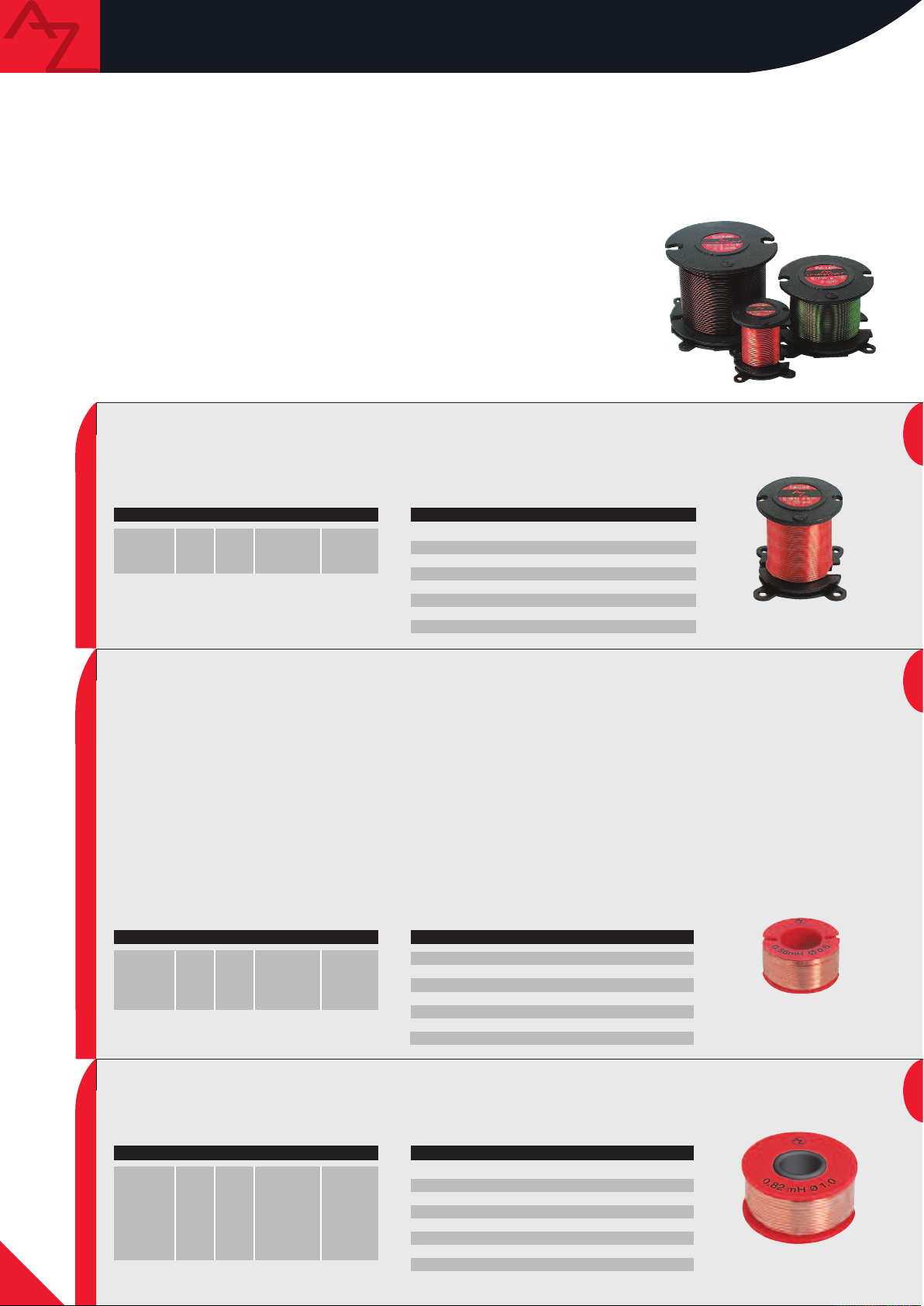
audiocoil
Con la linea audiocoil, AZ audiocomp introduce una serie di
innovazioni nel settore degli induttori. Per la loro costruzione
sono stati impiegati tecniche e materiali rivoluzionari e il loro
design è stato pensato per ottenere le migliori prestazioni e
funzionalità. Il supporto, progettato per avere la massima
versatilità di montaggio, ha una serie di attacchi per essere
fissato in modo stabile e in più posizioni con fascette o viti; è
stato definito un nuovo dispositivo autoserrante del filo che
consente di variare con facilità l’induttanza del componente,
eliminando il rischio di successive perdite di compattezza
dell’avvolgimento che porterebbero a un parziale degrado delle
qualità dell’induttore. Particolare attenzione è stata prestata
alla sicurezza del componente, realizzando il supporto in
materiale autoestinguente.
Le bobine sono avvolte in aria o su nuclei plaincore
®
ad alta
permeabilità magnetica ed elevato flusso di saturazione. Gli
avvolgimenti, particolarmente compatti, sono realizzati con
rame purissimo di sezioni elevate. I lunghi reofori degli
audiocoil sono prestagnati in modo da poter essere saldati
immediatamente senza dover ricorrere a interventi dannosi
first
TECHNICAL FEATURESART. L mh R Ω Core Reel
FA015
A022
F
FA
A033
F
0.15
.22
0
.33
0
0.35
.45
0
.50
0
Air
A
A
ir
ir
S 32.36
32.36
S
32.36
S
C
Ø
CU purity
Insulation
Standard
Tolerance
Body
Temperature
olor
Copper wire
per l’integrità dell’avvolgimento. Le proporzioni geometriche
degli audiocoil non sono frutto di una scelta casuale, ma
sono state pensate per ottimizzare il coefficiente di
autoinduzione dell’induttore e minimizzare la resistenza
interna della bobina. Quest’insieme di particolarità tecniche
consente agli audiocoil di sopportare elevate potenze e di
garantire un comportamento trasparente al segnale audio.
Gli audiocoil
first, best e sonus si
differenziano per il materiale
isolante dell’avvolgimento, oltre
a distinguersi tra loro per il
diametro del filo (0.71, 1, e
1.32 mm rispettivamente). Gli
audiocoil
first hanno una
smaltatura isolante di colore
rosso; i
best di colore verde. Gli
audiocoil sonus hanno invece un
particolare isolante, realizzato con
componenti ceramiche e polimerizzato
a raggi infrarossi.
ed
R
.71 mm
0
99.99%
1500 V
DIN 1787
±2% a 25°C @ 1kHz
Self-extinguishing V0
135° C max
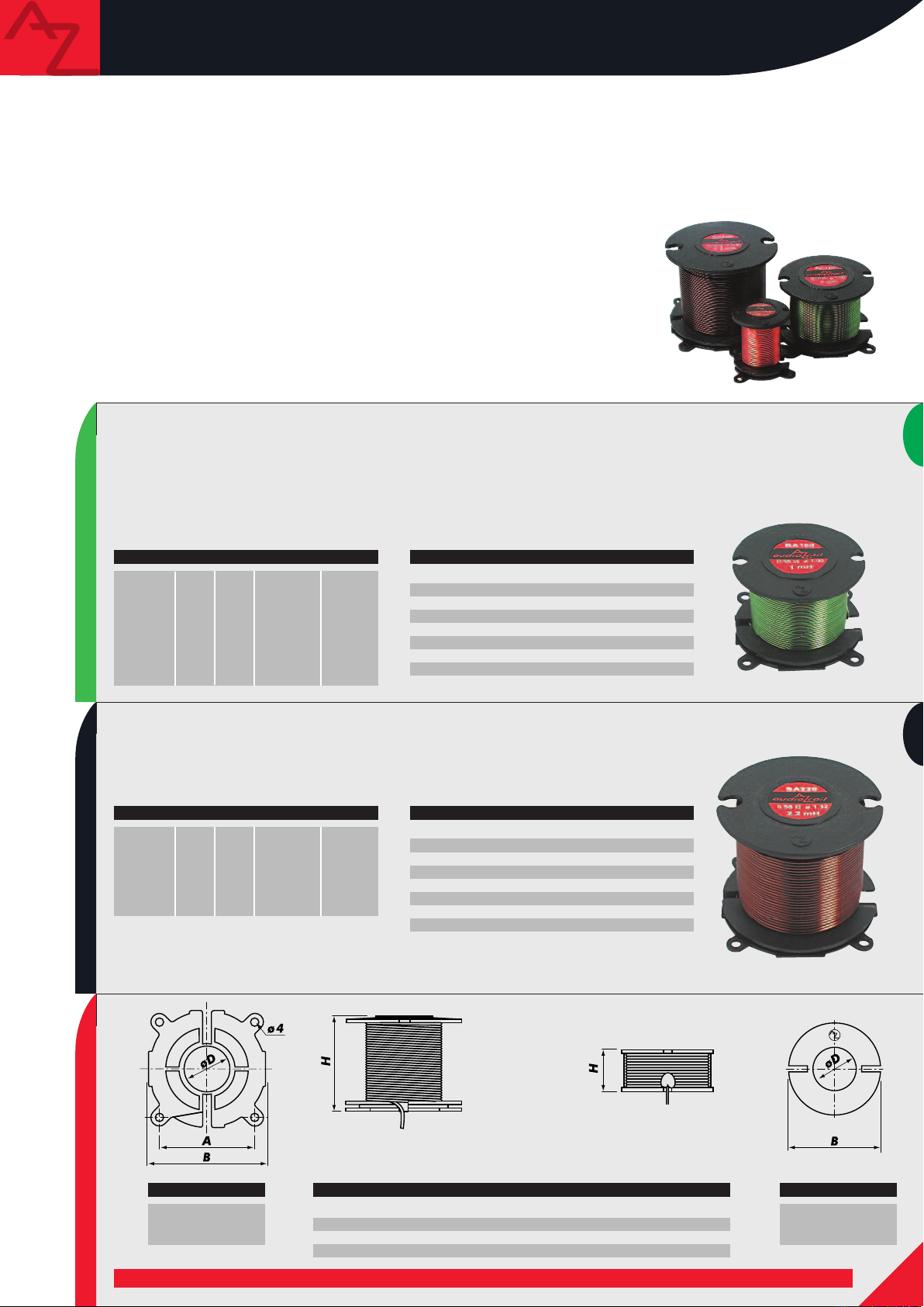
first
Gli audiocoil first si completano con due nuove serie di induttori
sviluppati rispettando le qualità costruttive degli audiocoil
AZ audiocomp: prestazioni elevate, soluzioni tecniche di alto
livello e facilità di montaggio. Il supporto, studiato per contenere al
massimo le dimensioni esterne, è realizzato in materiale altamente
elastico e resistente, è autoestinguente e caratterizzato dal colore
rosso e riporta tutti i dati che possono identificare immediatamente
le bobine. Gli induttori di maggior valore sono avvolti su nuclei
roundcore® ad alta permeabilità, che oltre a ridurre ulteriormente
gli ingombri totali di installazione, sono progettati per garantire il
miglior accoppiamento magnetico con l’avvolgimento. Diversificati
per diametro del rame, 0.6 mm per la linea
linea
first large, gli induttori sono dotati di lunghi reofori
prestagnati che ne semplificano l’utilizzo sia nel caso di cablaggio
SMALL
in aria che nel caso di montaggio su basetta universale.
ART. L mh R Ω Core Reel
SPB 015
SPB 033
SPB 047
SPB 056
0.15
0.33
0.47
0.56
0.36
0.61
0.71
0.79
Air
Air
Air
Air
first small e 1 mm per la
S 30.15
S 30.15
S 30.15
S 30.15
first
audiocoil first line includes two new series of inductors that
were designed according to AZ audiocomp typical building
quality demands: very good performances, high level technical
solutions and easy installation.
Their reel was conceived in order to be as small as possible; it
is made of very elastic, resistant and self-extinguishing
material, it is red and shows all the data that permit to
immediately identify coils themselves. The biggest inductors
have high permeability roundcore® cores which reduce the
space necessary to the installation and are designed to insure
the best magnetic matching with the winding.
first large inductors differ for their wire diameter (0.6mm and
1mm respectively); they have long, tinned rheophores that make
their use easier both when they are assembled onto printed
circuit boards and on wires.
TECHNICAL FEATURES
Color
Ø Copper wire
CU purity
Rheophores
Insulation
Standard
Tolerance
Natural
0.63 mm
99.99%
40 mm tin plated
1500 V
DIN 1787
±2% a 25°C @ 1kHz (air)
first small and
ART. L mh R Ω Core Reel
LPB 047
LPB 056
LPB 068
LPB 082
LARGE
LPB 100
LPB 150
LPB 180
0.47
0.56
0.68
0.82
1.00
1.50
1.80
0.20
0.23
0.26
0.25
0.31
0.37
0.43
Roundcore
Roundcore
Roundcore
Roundcore
Roundcore
Roundcore
Roundcore
S 38.18
S 38.18
S 38.18
S 43.26
S 43.26
S 43.26
S 43.26
TECHNICAL FEATURES
Color
Ø Copper wire
CU purity
Rheophores
Insulation
Standard
Tolerance
Natural
1.00 mm
99.99%
40 mm tin plated
1500 V
DIN 1787
±2% a 25°C @ 1kHz (air)
±5% a 25°C @ 1kHz (Roundcore)
4
Page 7
audiocoil
With audiocoil line, AZ audiocomp introduce s some
innovatio ns in the field of inducto rs. New techniques
and materials were used for th eir construction; t heir
design was conceived in order to ach ieve the best
perform ances and functionality. Their reel, design ed
in order to i nsure maximum mounting versatil ity, has
some hooks in order to be fixed steadily and i n
different positions th rough cable t ies or screws. We
created a new self-fastening device for the wire, that
permits to easily change the component inductance,
preventing wi nding com pactness losses that m ight
partially spo il the inductor qualities. Special
attention was paid to safety, making the reel of selfextinguishing material.
Coils are air-core ones or they have high magnetic
permeabil ity and saturation flux plaincore
®
cores.
Windings a re very comp act and made of thick, pu re
copper wire. audiocoil inducto rs long rheophores are
tinned in order to be immediately s oldered without
best
RT. L
A
BA022
BA
BA033
BA047
BA068
BA100
BA220
BC330
BC560
mh R Ω C
0.22
0.26
0.33
0.30
.47
0
.35
0
0.68
0.45
1.00
0.55
2.20
0.80
3.30
0.60
5.60
0.85
ore Reel
Air
Air
ir
A
Air
Air
Air
Plaincore
Plaincore
S 32.36
S 56.40
56.40
S
S 56.40
S 56.40
S 56.40
S 56.40
S 56.40
T
Color
Ø Copper wire
CU purity
Insulation
Standard
Tolerance
Body
Temperature
damaging the wire. audiocoil inductors size was
designed in order to optimise bobbin self-induct ion
coefficient a nd to mini mise coil internal resistance.
These technical feat ures allow audiocoil inductors to
stan d high powers and handle audio signal without
affecting it in any ways. audiocoil
sonus line s differ one from the other b ecause of
their winding insulating
material and wire diamet er
(0.71, 1 and 1.32mm
respectively). audiocoil
products have a red insul ating
enamelli ng while
have a green one. audiocoil
sonus indu ctors have a
special insu lation, m ade of
ceramic components and
polymerised at infrared rays.
ECHNICAL FEATURES
Green
1.00 mm
99.99%
1500 V
DIN 1787
±2% a 25°C @ 1kHz
Self-extinguishing V0
Max 135°C
first, best a nd
first
best one s
sonus
ART. L mh R Ω Core Reel
SA022
SA047
SA068
SA
SA100
SA220
SC10
0.22
0.47
0.68
1.00
2.20
10.0
0.14
0.20
0.25
0.33
0.55
0.73
Air
Air
Air
Air
Air
Plaincore
S 56.40
S 56.40
S 56.40
S 56.40
S 67.54
S 67.54
TECHNICAL FEATURES
Color
Ø Copper wire
CU purity
Insulation
Standard
Tolerance
Body
Temperature
Black
1.32 mm
99.99%
1500 V
DIN 1787
±2% a 25°C @ 1kHz
Self-extinguishing V0
Max 135°C
ART.
REEL SIZE
S 32.36
S 56.40
S 67.54
SIZE S 32.36 S 56.40 S 67.54
A
B
D
H
28
32
13
36
46
56
25
40
52
67
25
54
S 30.15
/
30
16
15
S 38.18
/
38
10
18
S 43.26
/
43
/
26
ART.
S 30.15
S 38.18
S 43.26
5
Page 8
audiofarad
I condensatori AZ audiocomp nascono da un’accurata
selezione dei materiali utilizzati per le armature, i
dielettrici e i supporti, allo scopo di ottenere: bassa
impedenza, stabilità in temperatura e nel tempo, ottimo
comportamento al variare della frequenza, capacità di
sopportare correnti elevate. Gli audiofarad sono
disponibili in una vasta gamma di valori e di tipologie
costruttive, per soddisfare tutte le esigenze. Le eccellenti
caratteristiche tecniche sono l’arma vincente in ogni
installazione e al momento dell’ascolto mostrano qualità
sonore tali da far passare in secondo piano qualsiasi altra
valutazione.
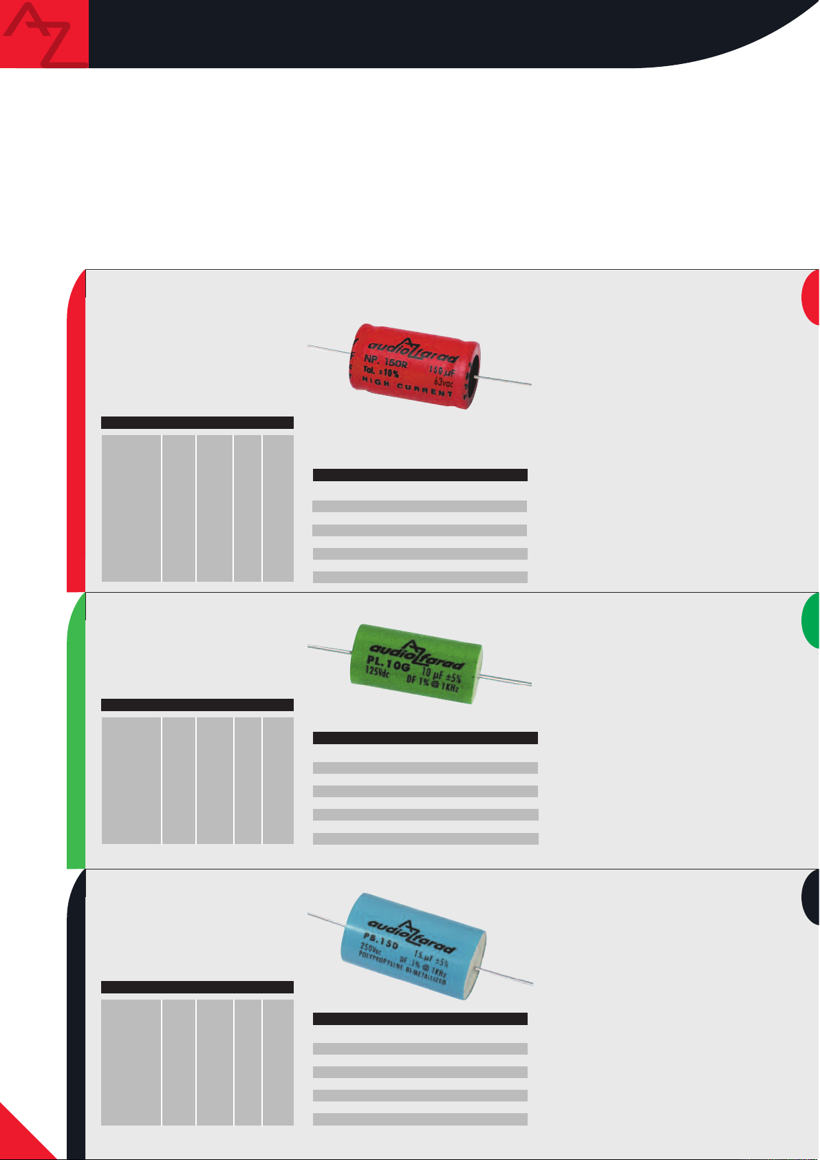
first
RT. C
A
NP.1R5
NP.2R2
NP.3R3
P.4R7
N
P.8R2
N
NP NON POLARIZED
P.22R
N
NP.33R
NP.47R
NP.68R
NP.100R
NP.150R
NP.220R
µF D mm L mm d mm
8
1.5
2.2
3.3
4.7
8
2
3
47
68
100
150
220
.2
2
3
9
1
8
19
0
1
4
2
0
1
4
2
3
1
6
2
13
32
13
32
13
32
18
36
22
41
22
41
22
41
0
0.6
0
0
0
0.8
0.8
0.8
0.8
0.8
0.8
0.8
.6
.6
.6
.8
TECHNICAL FEATURES
olor
C
late
P
ielectric
D
Rated voltage
Tolerance
Max D.F.
Temperature
Standard
AZ audiocomp capacitors derive from an accurate
selection of materials used for foils, dielectrics and
reels in order to get low impedance, constant features in
time and regardless of temperature, very good
performances when frequency varies, capacity to stand
high currents.
audiofarad capacitors are available in a wide range of
values and typologies in order to satisfy all needs. Their
acoustic qualities are such that their excellent technical
features fade into the background.
ondensatori elettrolitici non polarizzati,
C
ono caratterizzati da una bassa impedenza
s
interna e da un fattore di dissipazione
(D.F.) molto contenuto (inferiore al 10 % a
kHz). Hanno un ottimo comportamento alle
1
alte frequenze e sopportano correnti
elevate. La tolleranza contenuta al 10% e
l’elevata stabilità delle prestazioni nel
empo li rendono affidabili e adatti ad
t
ssere impiegati con successo in tutti gli
e
impianti.
Non-polarised electrolytic capacitors
Red
luminum
A
lectrolyte
E
00Vdc/63Vac
1
±10% a 25˚C @ 1kHz
<10% @ 1kHz
-40˚C ÷ 85°C
DIN 1787
characterised by low internal impedance
nd very limited (less than 10% at 1kHz)
a
dissipation factor (D.F.). Their
performances are very good at high
frequencies and they can handle high
currents. Their tolerance limited to 10%
and constant performances make them
reliable and successfully usable in all
systems.
best
Gli
audiofarad PL combinano in un
perfetto equilibrio i fattori di D.F. e di
tolleranza ed assicurano la frequenza di
taglio reale identica a quella di progetto.
ART. C µF D mm L mm d mm
1.0
7
19
PL.1G0
PL.2G2
PL.2G7
PL.3G3
PL.3G9
PL.4G7
PL.5G6
PL.6G8
PL POLYESTER METALLIZED
PL.8G2
PL.10G
2.2
2.7
3.3
3.9
4.7
5.6
6.8
8.2
10
9
9
10
9
10.5
11
12.5
13
14
0.8
27
0.8
27
0.8
27
0.8
32
0.8
32
0.8
32
0.8
32
0.8
32
0.8
32
0.8
TECHNICAL FEATURES
Color
Plate
Dielectric
Rated voltage
Tolerance
Max D.F.
Temperature
Standard
Green
Metallized Film
Polyester
125Vdc/70Vac
±5% a 25˚C @ 1kHz
<1% @ 1kHz
-40˚C ÷ 85°C
DIN 1787
sonus
ART. C µF D mm L mm d mm
1.0
PB.1D0
PB.1D5
PB.2D2
PB.3D3
PB.3D9
PB.4D7
PB.5D6
PB.6D8
PB.22D
PB.47D
1.5
2.2
3.3
3.9
4.7
5.6
6.8
22
47
11
13.5
16
20
18
20
22
24
36
41
PB POLYPROPYLENE BI-METALLIZED
6
0.8
32
0.8
32
0.8
32
1.0
32
1.0
39
1.0
44
1.0
44
1.2
44
1.2
53
1.2
57
TECHNICAL FEATURES
Color
Plate
Dielectric
Rated voltage
Tolerance
Max D.F.
Temperature
Standard
Light blue
Bi-Metallized Film
Polypropylene
400Vdc/250Vac
±5% a 25˚C @ 1kHz
<0,1% @ 1 kHz
-40˚C ÷ 85°C
DIN 1787
Ottimo comportamento in frequenza e in
potenza e proprietà acustiche di livello
elevato sono le qualità tecniche che li
collocano ai vertici del mercato,
permettendo la realizzazione di crossover
di altissimo livello.
audiofarad PL capacitors perfectly
combine D.F. and tolerance factor and
insure the same cut-off frequency as the
designed one. Their good performances at
high frequencies and power and excellent
acoustic features allow the realisation of
very high level crossovers.
I condensatori al polipropilene bi-metallizzati
audiofarad PB hanno un D.F.
praticamente trascurabile (<0.1% a 1kHz) che
dà loro un’assoluta costanza delle prestazioni
al variare della frequenza. La realizzazione
dell’armatura con doppia metallizzazione, in
grado di sopportare tensioni fino a 400 Vdc,
caratterizza e rende unici questi
condensatori: una scelta obbligata per tutti
coloro che vogliano costruire crossover da
utilizzare in coppia con amplificatori di
elevato livello e di alta potenza.
audiofarad PB polypropylene
bi-metallized capacitors have negligible D.F.
(<0.1% at 1kHz), which makes their
performances absolutely constant when
frequency varies. Their foil made through
double metalization, able to stand voltages
up to 400 Vdc, makes these capacitors
unique. They are an unavoidable choice for
all those who want to build crossovers to use
with high quality power amplifiers.
Page 9
audiofarad
Il condensatore carta e olio è il massimo per la costruzione
di sistemi audio no-compromise. Gli audiofili ne
conoscono e apprezzano le qualità sonore, ma per la scarsa
disponibilità sul mercato sono costretti a rinunciare a
questo tipo di prodotto. AZ audiocomp ne propone due
diversi tipi: audiofarad OL e audiofarad OLC.
Questi condensatori, dotati di un contenitore metallico
che fornisce la schermatura passiva, sono ricoperti
da un elegante guscio nero con serigrafie oro che li
rendono unici anche sotto il profilo estetico. La singolarità
e l’eccezionalità ne fanno i protagonisti assoluti di
apparecchiature esoteriche Hi-End.
sonus
ART. C µF D mm L mm d mm
L.3M3
O
3.3 40 55 0.8
OL OIL-ALUMINIUM FOIL HI-END CROSSOVER PART
TECHNICAL FEATURES
Color
Plate
Dielectric
Rated voltage
Tolerance
Max D.F.
Temperature
Paper and oil capacitor is the best for realising
no-compromise audio systems. The most demanding
audiophiles know and appreciate its sound qualities but
they are forced to give up this product because they
cannot find it into the market. AZ audiocomp offers
two different types: audiofarad OL and
audiofarad OLC. These capacitors have a metallic
housing which provides them with passive shielding.
Their elegant black sleeve with golden silkscreen print
also make them cosmetically unique. Their excellence
makes them the protagonists of hi-end esoteric systems.
Gli audiofarad OL sono condensatori ad
lio minerale purissimo con armature in
o
foglio di alluminio. Hanno un D.F. inferiore
a 0.01% che rende il loro comportamento
ssolutamente neutro con il variare della
a
requenza e della potenza. Questi
f
componenti, per il loro gran pregio, sono
venduti soltanto in coppie selezionate al
entesimo in modo da permettere di
c
ealizzare circuiti dalle caratteristiche
r
sonore uniche.
re very pure mineral oil
Black
Aluminum
Paper + Mineral Oil
100Vdc
±0% a 25˚C @ 1kHz
0.01% @ 1kHz
-40˚C ÷ 85°C
audiofarad OL a
apacitors with aluminium foils. Their D.F.
c
is lower than 0.01% and prevents them
rom being affected by frequency and power
f
variations. These components are selected
and coupled according to value, then they
are sold only in pairs, in order to allow the
realisation of circuits with unique sound
features.
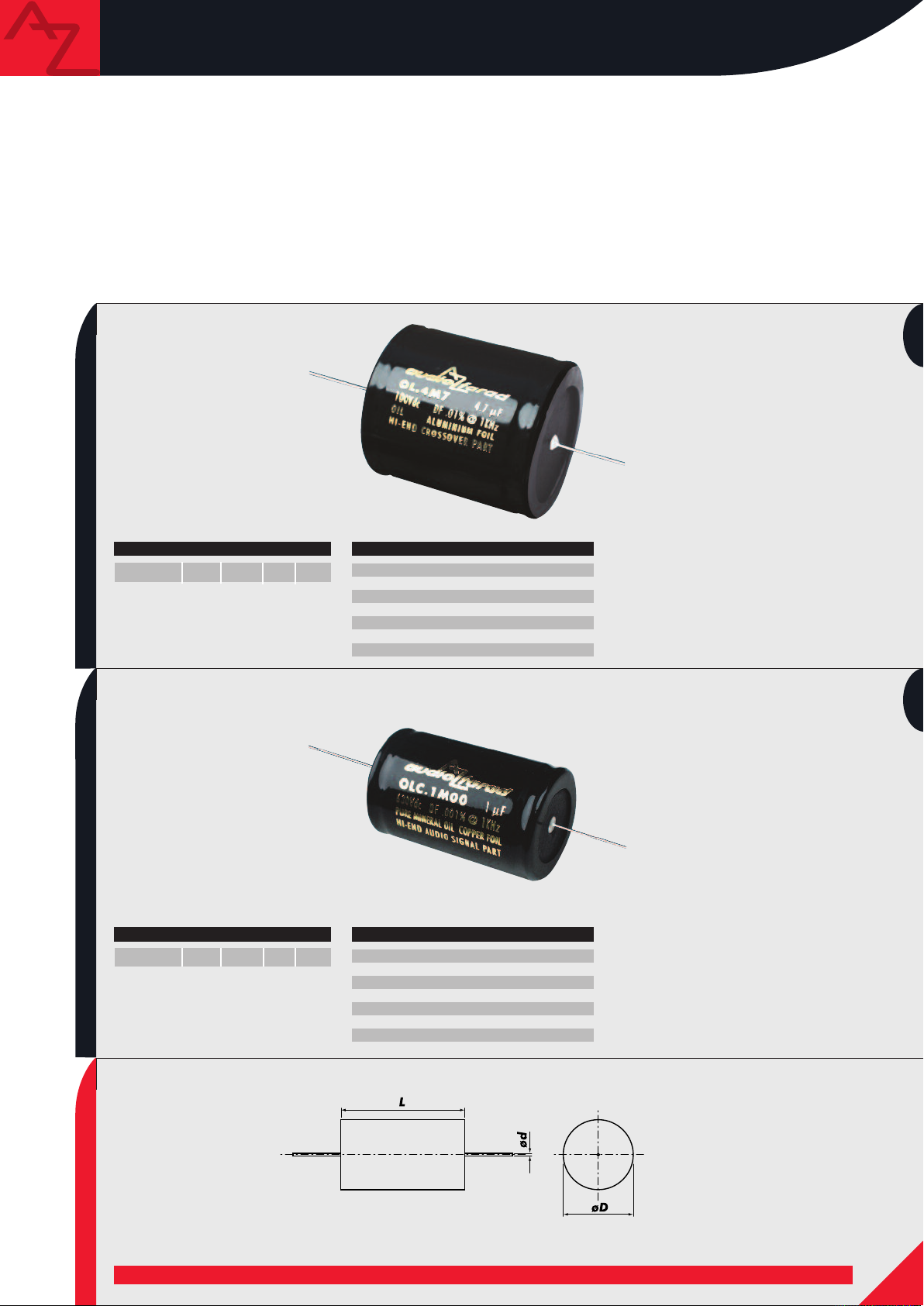
sonus
ART. C µF D mm L mm d mm
OLC.1M00
OLC PURE MINERAL OIL HI-END AUDIO SIGNAL PART
1.00
35 55 0.8
TECHNICAL FEATURES
Color
Plate
Dielectric
Rated voltage
Tolerance
M ax D.F.
Temperature
Black
Copper
Paper + Mineral Oil
630Vdc
±0% a 25˚C @ 1kHz
0.001% @ 1kHz
-40˚C ÷ 85°C
audiofarad OLC hanno le stesse
Gli
caratteristiche degli
differiscono per la tensione che sono in
grado di sopportare e per le armature
costituite da foglio di rame, da cui il
suffisso C, derivato da Cu simbolo chimico
del rame. Le loro caratteristiche tecniche li
rendono particolarmente adatti per la
realizzazione di circuiti pre e finali “state
of the art”. Sono disponibili singolarmente
per facilitare chi necessiti di un solo pezzo
alla volta (ad esempio per pre e finali
mono d’eccezione).
OL, ma da questi
audiofarad OLC have the same features
OL but differ from them because of the
as
voltage they can handle and of their copper
foils (C suffix derives from Cu, copper
chemical symbol). They are particularly
suitable for building pre circuits and
state-of-the-art amplifiers. They are sold
individually to satisfy even those who need
just one piece of them (for pre and unique
mono amplifiers).
SIZE
7
Page 10
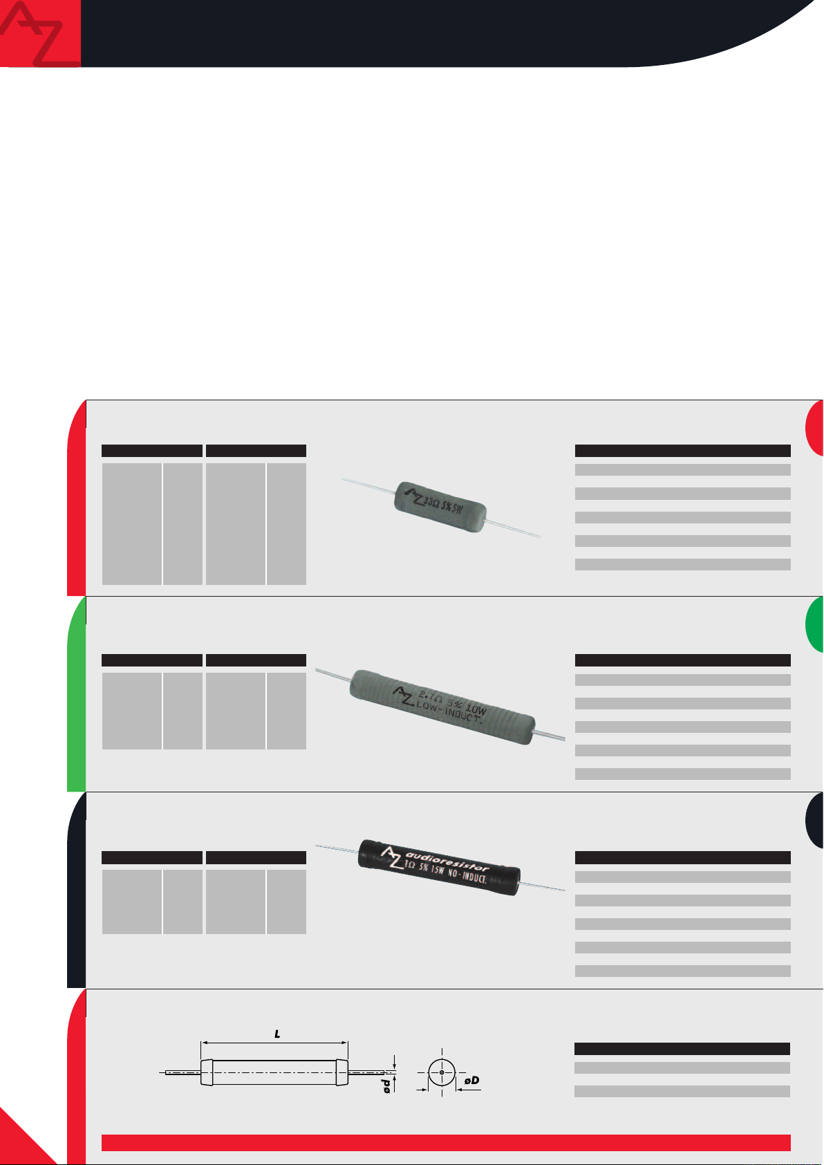
audioresistor
Gli audioresistor sono resistori a filo di rame su nucleo
dissipatore in ceramica appositamente realizzati per
impiego audio. Sopportano un’elevata potenza di picco ed
hanno una bassa componente induttiva parassita. Le serie
first e best, che si distinguono per il colore grigio e per
le potenze continue sopportate di 5 e di 10W, sono
costruite con uno speciale avvolgimento “low inductance”,
collegato a dei terminali a cappuccio metallico che
garantiscono un’alta insensibilità alle vibrazioni e una
grande capacità di dissipazione termica. La serie sonus,
che è di colore nero e sopporta una potenza continua di
15W, ha la singolare caratteristica di impiegare la
tecnologia biwiring Ayrton Perry per l’avvolgimento delle
spire e di utilizzare un isolante siliconico. Questa tecnica
permette di eliminare completamente le componenti
induttive dei resistori a filo. Ridotte dimensioni,
materiali ignifughi con i quali sono costruiti, capacità di
sopportare notevolissimi picchi istantanei di corrente e
costanza di prestazioni al variare della temperatura sono
le caratteristiche vincenti di prodotti eccezionali. La vasta
gamma di valori disponibili permette i più sottili
aggiustamenti senza dover ricorrere a soluzioni
alternative, per ottenere sempre realizzazioni
“no-compromise”.
first
R5
ART. R Ω
R5.B22
5.B33
R
5.B47
R
5.B56
R
R5.B68
R5.1B0
R5.1B5
R5.1B8
R5.2B2
R5.2B7
.22
0
.33
0
.47
0
0.56
0.68
1.0
1.5
1.8
2.2
2.7
ART. R Ω
5.3B3
R
5.4B7
R
R5.5B6
R5.8B2
R5.10B
R5.15B
R5.22B
R5.33B
R5.47B
3
4.7
5.6
8.2
10
1
22
33
47
.3
5
Resistori a bassa induttanza parassita
audioresistor components are copper wire resistors
with ceramic core, especially made for audio use. They
handle high peak power and have low inductance.
and best series, which are grey and handle 5W and
10W RMS respectively, have a special “low inductance”
winding connected to some metallic cap terminals that
insure high vibrations rejection and thermal dissipation.
sonus series, which is black and can stand 15W RMS,
uses Ayrton Perry bi-wiring technology for turns
winding and employs silicon insulation. This technique
allows the complete elimination of wire resistors
inductance. Their small size, the anti-fire materials they
are made of, the ability to stand very notable peak
powers and their constant performances when
temperature varies are the successful features of unique
products. The wide range of available values allows the
subtlest adjustments without having to use alternative
solutions, in order to always get “no compromise”
realisations.
ECHNICAL FEATURES
T
Color
Nominal power
Tolerance
emperature coef.
T
emperature
T
ax power
M
Insulation voltage
Body
Standard
Low inductance resistors
first
Grey
5W
± 5%
250 PPM/°C
±
00°C max
2
5W for 5 sec.
2
500V
Silicon-ceramic
DIN 1787
best
ART. R Ω
R10.1B0
R10.1B5
R10.2B2
R10.2B7
R10
R10.3B3
R10.4B7
sonus
ART. R Ω
R15.1B0
R15.1B5
R15.2B2
R15.3B3
R15
R15.3B9
1.0
1.5
2.2
2.7
3.3
4.7
1.0
1.5
2.2
3.3
3.9
ART. R Ω
R10.5B6
R10.6B8
R10.8B2
R10.10B
R10.47B
ART. R Ω
R15.4B7
R15.5B6
R15.6B8
R15.15B
5.6
6.8
8.2
10
47
4.7
5.6
6.8
15
Resistori a bassa induttanza parassita
Low inductance resistors
Resistori con isolamento siliconico avvolti con
tecnologia Ayrton Perry
Resistors with silicone insulation wound through
Ayrton Perry technology
TECHNICAL FEATURES
Color
Nominal power
Tolerance
Temperature coef.
Temperature
Max power
Insulation voltage
Body
Standard
TECHNICAL FEATURES
Color
Nominal power
Tolerance
Temperature coef.
Temperature
Max power
Insulation voltage
Body
Standard
Grey
10W
± 5%
± 250 PPM/°C
200°C max
50W for 5 sec.
500V
Silicon-ceramic
DIN 1787
Black
15W
± 5%
± 100 PPM/°C
200°C max
150W for 5 sec.
1500V
Silicon-ceramic
DIN 1787
SIZE L mm D mm d mm
R5
R10
R15
24,5
53
51
8,5
8,5
8
0,85
0,85
0,85
SIZE
8
Page 11
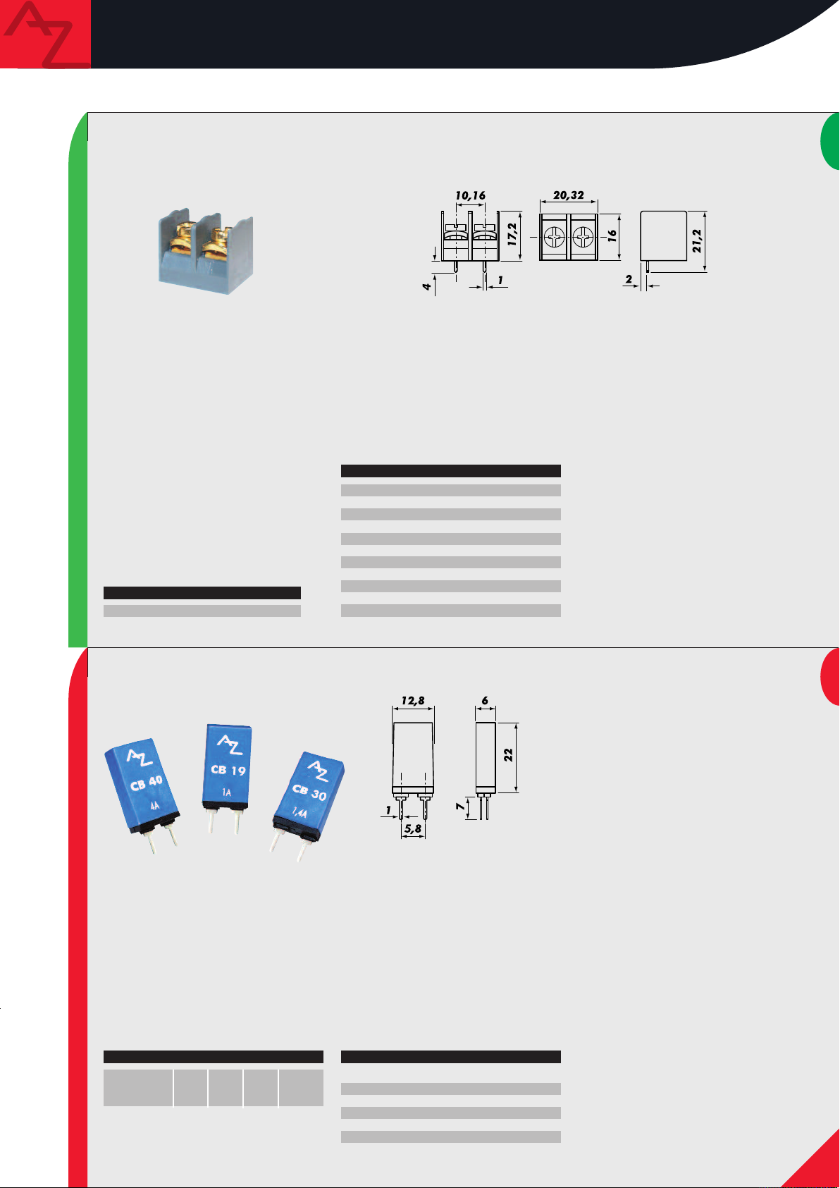
audioboard accessories
best
TERMINAL BLOCK
ART.
BTB 20
TECHNICAL FEATURES
olor
C
erminal clamp
T
Rated voltage
Insulation voltage
Rated current
Connecting capacity
Body
Temperature
lack
b
in plated brass
T
with gold-plated
screw
500V max
6000Vac
24A max
Cross point screw
2 x 12AWG
Self-extinguishing V2
-40°C÷80°C
Terminali da circuito stampato di altissima
ualità. La connessione è costituita da un
q
upporto in ottone massicciamente dorato
s
con vite con testa a croce, in grado di
sopportare elevatissime potenze e di
ccettare cavi da 12 AWG. Il loro design è
a
tudiato per ottenere una morsettiera
s
multipla semplicemente affiancando più
connettori, per risolvere funzionalmente ed
steticamente complessi circuiti crossover.
e
a qualità di una realizzazione si vede
L
nche dai dettagli.
a
ery high quality terminals for printed
V
circuit boards. Connection consists of a
gold-plated brass body with cross-headed
screw, that can stand very high powers and
accept 12 AWG wires. Their design permits
to get a multiple terminal block by putting
several connectors side by side, in order to
functionally and cosmetically build complex
crossover circuits. The quality of an
installation can be seen even in the details.
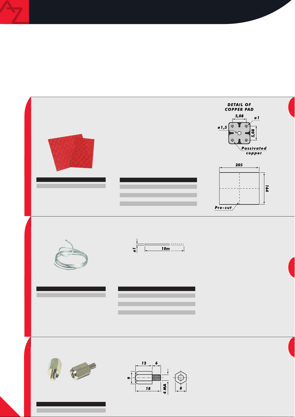
Interruttori a coefficiente di temperatura
positivo. I CB sono la soluzione al
problema della protezione degli
altoparlanti contro il sovrapilotaggio.
Questi componenti reagiscono al passaggio
di corrente alterando il proprio stato:
interrompono il contatto all’aumentare
della temperatura, salvo ripristinarsi
automaticamente dopo il ritorno alle
normali condizioni. Realizzati su supporto
autoestinguente, sono studiati per essere
il più trasparente possibile al passaggio
CIRCUIT BREAKER
ART. A
CB 19
CB 30
CB 40
RMSR mΩA MAXW RMS-4Ω
1.9
<75
3.0
4.0
<35
<35
20A
30A
40A
15
36
64
TECHNICAL FEATURES
Color
Rated voltage
Rated current
Time delay
Body
Light blue
200VDC max
AC @ 25°C
<30sec @ 200% A
<5sec @ 300% A
Self-extinguishing V0
del segnale, nel massimo rispetto della
qualità audio.
PTC circu it brea kers. They protect
spea kers from overload. They react to
current pa ssage by changing th eir
statu s: they interru pt contact wh en
temperature increases and automatically
reset when functioning conditions get
normal again. They ha ve a
self-extinguishing b ody and they are
designe d in ord er not t o affect s ignal,
respecti ng audio quality.
9
Page 12
audioboard
Gli audioboard sono il naturale completamento della
gamma dei componenti per crossover passivi; questi
circuiti stampati sono forniti in due versioni: nella linea
first la piastra è in Bachelite, mentre nella linea best è in
Vetronite con le piazzole in rame di elevato spessore. La
disposizione standard dei fori è stata integrata e
migliorata dal particolare disegno del rame passivato
(pronto per essere saldato) e dall’aggiunta di un foro da
1.5 mm che può accogliere anche i terminali di elevata
sezione delle bobine sonus. I quadrotti, di spessore
1.6 mm, sono pre-tagliati in modo da poter essere
utilizzati in tre differenti formati, mantenendo sempre la
piena robustezza del circuito.
first
MAINBOARD
F
ART.
2 CS
TECHNICAL FEATURES
Color
Body
Size BxLxH
CU
Temperature
audioboard products complete the range of components
for passive crossovers. These printed circuit boards are
available in two versions: in
bakelite while in
best line it is made of glass fibre with
first line, board is made of
thick copper pads. The holes standard layout was
improved through the special design of passivated copper
(ready to be soldered) and through the addition of a
1.5mm hole which can accept even
sonus coils big
terminals. Squares, 1.6mm thick, are pre-cut in order to
be used in three different sizes, without affecting the
circuit sturdiness.
Red
Bachelite (FR2)
164 x 205 x 1.6 mm
35µm
-50°C ÷ 130°C
10
Cavo in rame purissimo all’argento. La
bassissima resistenza per cm lineare, la
perfetta saldabilità, la duttilità del rame
unita alla notevole sezione, la quale
garantisce grandi capacità in corrente, ne
fanno un vero gioiello per la
realizzazione di crossover passivi allo
ART.
CL 10
COPPER LINE
TECHNICAL FEATURES
Color
Body
ø Copper wire
Rated current
Resistance
Silver
Silver pure copper
1.00 mm
50A max
0.17 mΩ/cm
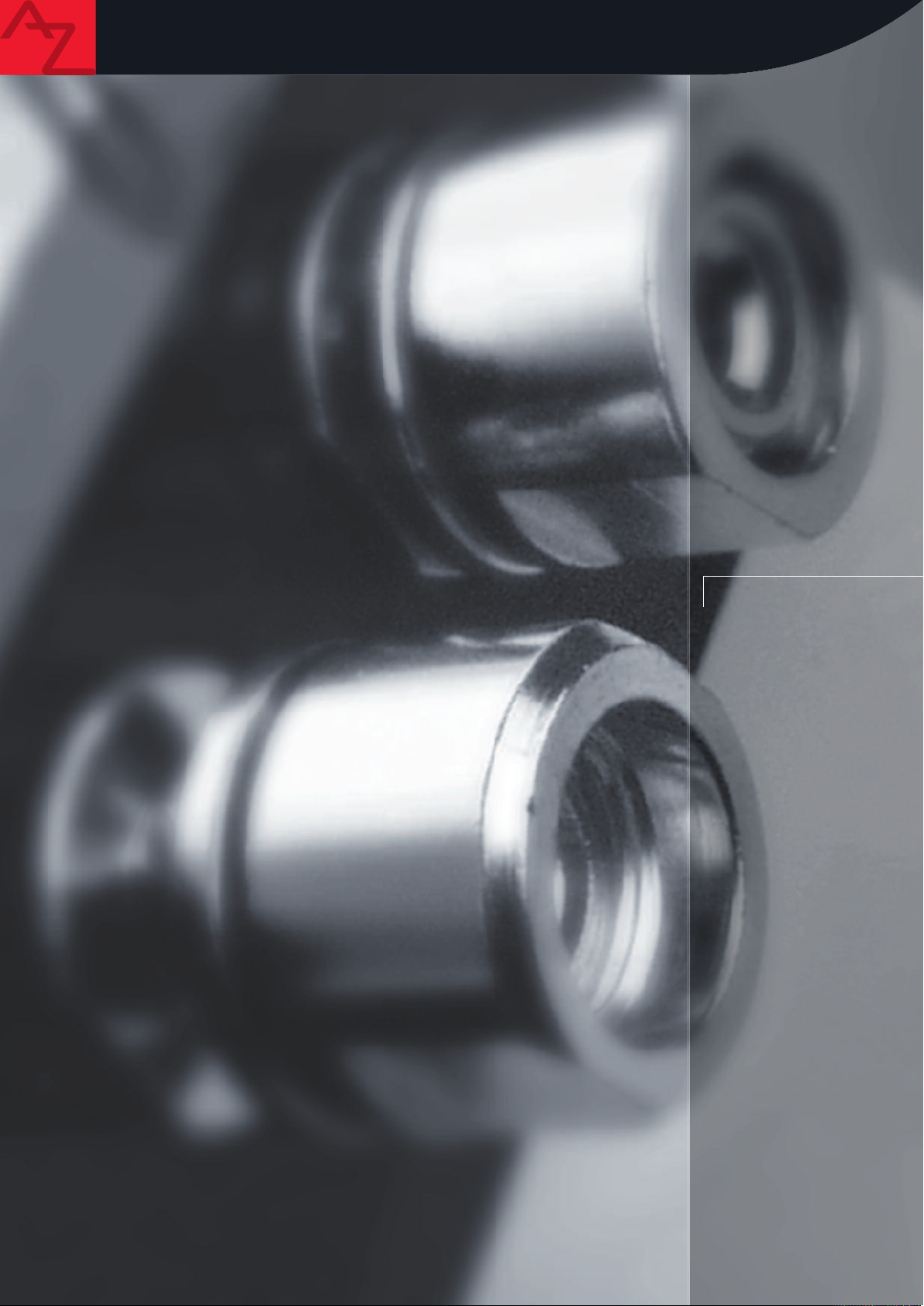
SPACER
ART.
SP 8-18
stato dell’arte.
Silver, pure copper wire. It is a real pearl
for realising state-of-the-art passive
crossovers thanks to its very low
resistance per centimetre, its perfect
weldability, copper ductility and big
section, which provides it with high
current capacity.
Spessori in alluminio tornito. Realizzati in
sezione esagonale per facilitare il
montaggio, possono accogliere viti in
standard 4 MA e sono componibili per
adattarsi a tutte le esigenze. Essenziali per
tenere separato il circuito dal supporto su
cui deve essere montato.
Machined aluminium spacers. Their section
is hexagonal to make mounting easier; they
can accept standard 4 MA screws and are
modular in order to be suitable to all
needs. They are necessary to separate the
printed circuit board from the support it
must be assembled onto.
Page 13
COMPONENTI
PER COSTRUZIONE
DIFFUSORI
COMPONENTS FOR
ENCLOSURES
Page 14
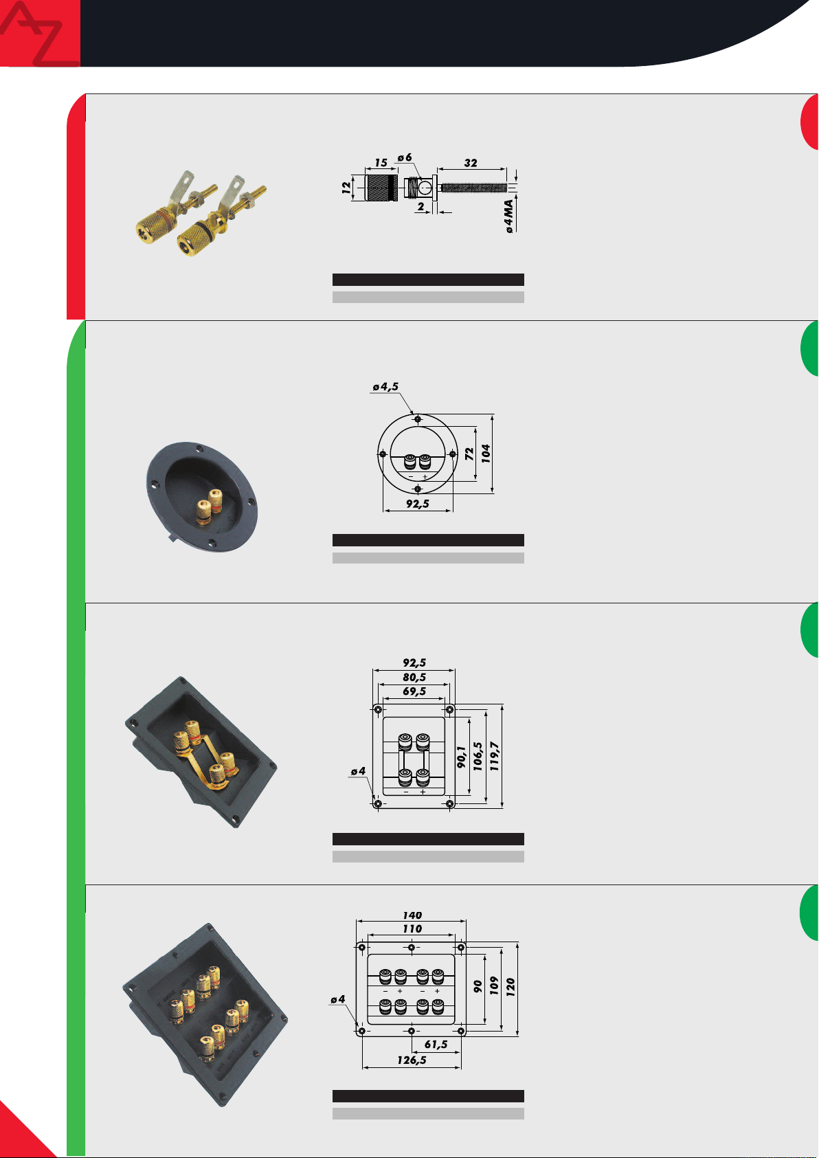
audioterminal
first
BINDING POST
best
RT.
A
AT 1G
ART.
AT 20G
oppia di connettori da pannello per
C
asse acustiche, realizzati in metallo
c
pieno massicciamente dorato. Possono
ssere montati su pannello di legno di
e
pessore fino a 30 mm. Accettano cavi da
s
mm di diametro e terminazioni a
6
banana da 4 mm.
old-plated, solid metal binding posts for
G
enclosures. They can be mounted on max.
30mm thick wooden panels. They accept
mm diameter cables and 4mm banana
6
erminals.
t
aschetta portaterminali rotonda da
V
76.5 mm per casse acustiche, terminata
con connettori stereo placcati ORO. Gli
udioterminal accettano cavi fino a
a
6 mm di diametro e tutti i tipi di
terminazione a banana da 4 mm o a
forcella presenti sul mercato. La flangia di
issaggio è dotata di una guarnizione
f
ntisfiato in neoprene.
a
6.5mm round binding cup for enclosures
7
ith gold-plated stereo connectors.
w
audioterminal devices accept max. 6mm
diameter cables and all 4mm banana or fork
terminals. The edge has an airtight
neoprene gasket.
Vaschetta portaterminali per casse
acustiche, terminata con connettori adatti
al Bi-Wiring e al Bi-Amping placcati ORO.
Accettano cavi di grosso diametro e
terminazioni a banana da 4 mm o a
forcella. I connettori sono ponticellati
per l’uso stereofonico tramite placche
dorate. La flangia di fissaggio è fornita
di una guarnizione antisfiato in
neoprene.
Binding cup fo r enclo sures, with
gold- plated connectors suitable to BiWiring and Bi-Amping. They accept big
diameter cab les and 4mm banana or for k
BINDING CUP
ART.
AT 40G
ART.
AT 80G
terminals. The bind ing cup termi nals are
conne cted in parallel t hrough gold-plat ed
jumpers. The edge has an airtight
neoprene gasket.
Terminale con otto connettori placcati
ORO che accettano cavi, connessioni a
forcella e connettori a banana da 4 mm.
Come tutti gli audioterminal sono dotati
di una guarnizione in neoprene che
assicura un montaggio senza sfiati e un
isolamento meccanico dal mobile su cui
sono montati.
Binding cup with eight gold-plated
connectors which accept cables, fork and
4mm banana terminals. Like the other
audioterminal devices, they have an
airtight neoprene gasket which also insures
mechanical insulation with the enclosure
they are installed onto.
12
Page 15

audioterminal
best
BINDING POST
A
ART.
T 2G
oppia di connettori da pannello placcati
C
RO 24kt. Grazie all’asse di oltre 30 mm
O
possono essere utilizzati per casse
custiche le cui pareti siano di notevole
a
pessore. Accettano cavi da 6 mm di
s
diametro e terminazioni a banana da
mm.
4
4Ct. gold-plated binding posts. They can
2
be used with very thick enclosures panels
thanks to their length (more than 30mm).
hey accept 6mm diameter cables and 4mm
T
anana terminals.
b
first
ART.
AC F
Connettori per diffusori realizzati in rame elettrolitico placcati in
ORO 24kt completi di guaine isolanti colorate per identificare la
polarità. Ideale per qualsiasi collegamento di potenza.
PLUG
I connettori SPEAK ON sono il massimo della tecnologia applicata alla sicurezza nei collegamenti
di potenza. La particolare struttura di questi connettori, realizzata in ABS, protegge i contatti
tenendoli separati ed evitando pericolosi cortocircuiti. Con un unico connettore è possibile
collegare fino a quattro poli e i terminali accettano cavi di grosso diametro offrendo una
grande superficie di contatto. L’esclusivo sistema di aggancio consente un serraggio rapido ed
efficace anche in presenza di forti vibrazioni garantendo la massima tenuta in ogni condizione.
SPEAK ON connectors represent maximum safety for power connections. Their special structure,
made of ABS, protects contacts by separating them and avoiding dangerous short circuits. It is
possible to connect up to four poles with a single connector; terminals accept big diameter
cables insuring big contact surface. Their exclusive hooking system allows quick and efficient
fastening even with strong vibrations, insuring the best contact in whatever conditions.
ART.
AC B1
24Ct. gold-plated, electrolytic copper speakers connectors with
coloured insulating sheath to identify polarity. They are ideal for
every power connection.
ART.
SPEAK ON F
TECHNICAL FEATURES
Color
Insulation voltage
Rated voltage
Contact rated current
Resistance
Cable range
Body
Temperature
Blue
1500VAC
250VAC max
20 A max
8mΩ
5 ÷ 15 mm
Self-extinguishing V0
-50°C ÷ 130°C
13
Page 16
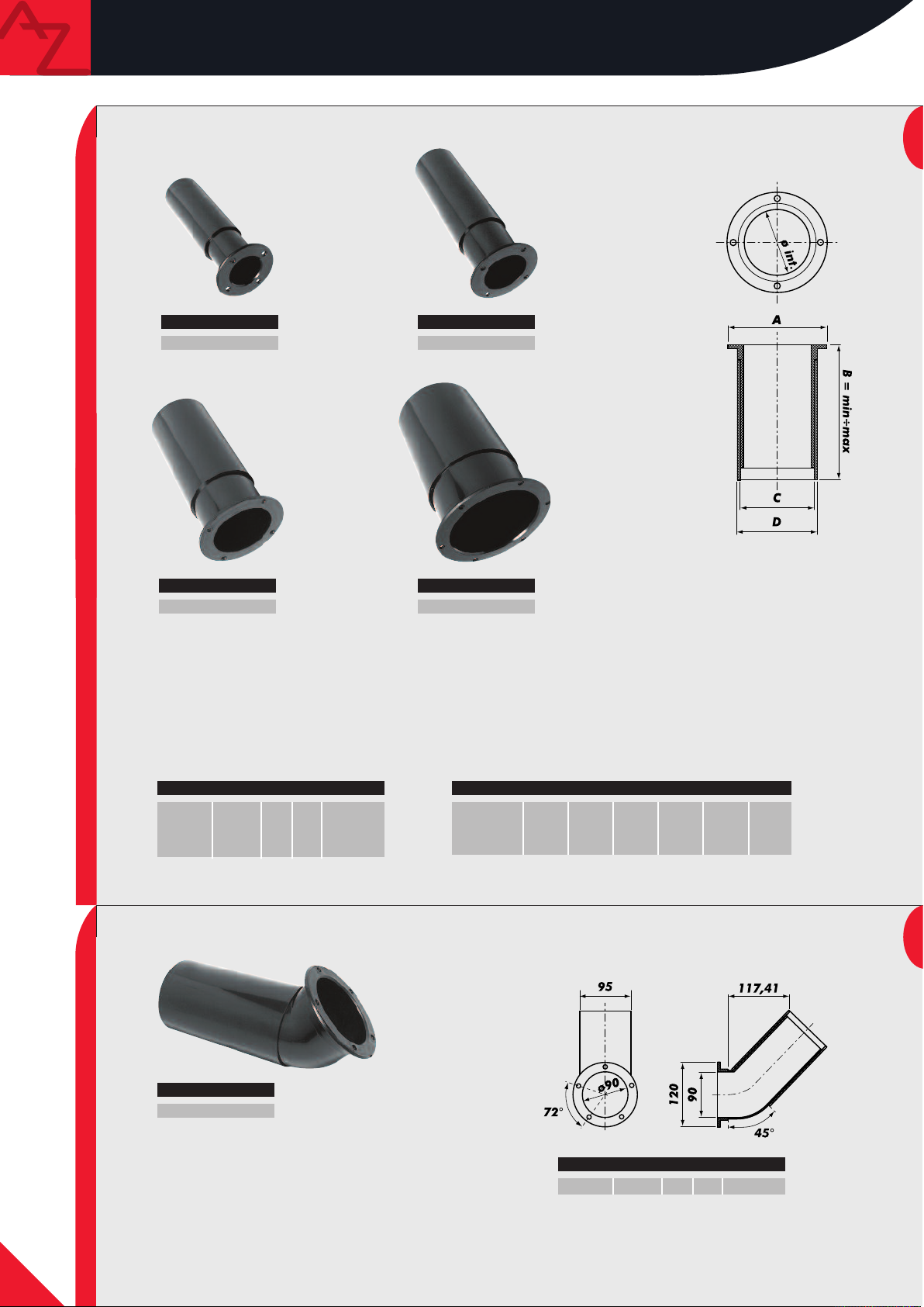
audioreflex
first
RT.
A
AR 40
RT.
A
AR 55
REFLEX PORT
first
RT.
A
AR 70
Gli audioreflex AR sono realizzati in PVC in cinque diverse misure, per coprire le esigenze di montaggio di
altoparlanti che vanno da 10 a 46 cm. Dotati di una flangia rigida che consente un facile fissaggio dall’esterno della
cassa, i tubi AR sono telescopici per potersi adattare comodamente a tutte le necessità e per consentire il perfetto
allineamento del reflex senza dover ricostruire interamente il sistema.
audioreflex AR tubes are made of PVC and are available in five different sizes for mounting speakers from 10 to 46cm
diameter. They have a rigid edge that permits to easily fix them from outside the enclosure. AR tubes are telescopic in
order to be suitable to all needs and to allow the reflex perfect alignment without rebuilding the whole system.
ART.
AR 40
AR 55
AR 70
AR 115
ø i
nt. min
35
50
66
110
L minL m
112
152
130
152
210
292
260
290
ax
ø m
165 mm
200 mm
300 mm
460 mm
ax speaker
RT.
A
AR 115
ART. Aø i
AR 40
AR 55
AR 70
AR 115
35
50
66
110
nt.
65
80
95,5
145
B minB m
112
152
130
152
210
292
260
290
ax
CD
40
55
71
116
45
60
80
121
14
ART.
AR 90A
Tubo reflex per box di medie dimensioni angolato
a 45°. Studiato per applicazioni estreme è la
soluzione perfetta per chi ha problemi di spazio
ANGLED PORT
con tubi tradizionali.
45° angled bass reflex tube for average size
enclosures. It is designed in order to be used in
extreme applications; it is the perfect solution
for those who have space problems when using
traditional tubes.
AR 90A
ART.
ø int. min
L min L max
85 210 380 380 mm
ø max speaker
Page 17

audioreflex
bes
t
A
A
RT.
R
6
5
V
A
RT.
A
R
8
0
V
VENTED PORT
A
RT.
A
R
1
0
0
V
Gl
i
au
Per evi
t
ubo di
e
per
dioreflex
ta
accordo. La
non crea
A
R
V sono s
tati
real
i
zz
at
r
e t
urbol
e
nz
e e
l
'i
nsorg
re
m
osta
odul
col
i all
a
rità de
a
ere
l
i
nea
i per raggiungere il m
di
fe
nomeni
i
pezzi
e
gli
rità di
f
lusso dell’aria.
di dis
incast
t
ri
meccanici
assi
orsione sono s
sono st
mo livello di
tat
e reali
udiati
SPL con subwoofer di
zzate profonde svasat
per avere la maggiore flessibilità possi
grandi
ure agli
di
mensioni.
es
t
remi
del
bile
au
di
m
ade
joi
n
ART.
AR 65V
AR 80V
AR100V
t
or
at t
s
eflex
he
w
ere
AR
V
e
nds o
designed
ø
int. min
60
75
95
t
f t
ube
L
s were
he re
i
n
min
105
125
145
flex
order
L
200
220
250
max
de
t
ube
t
o g
ø
signe
i
et
max
250 mm
320 mm
380 mm
d i
n order to achieve the highes
n
order to avoid t
a
s much flexi
speaker
urbulence and dis
bility as possible and not
AR 65V
AR 80V
AR100V
ART.
t
SPL wit
h big si
tortion. The pieces modularity and mechanical
t
o hi
ø
int.
62
105
82
125
100
145
ze subwoofers. Deep flari
nder ai
r flux linearity.
A
B
60
46,5
60
56
60
66,5
C
ø D
66
105
86
125
104
145
ngs were
ø E
F
194
223
253
15
Page 18

250
audioaccessories and grilles
GRILLE
RT.
A
GRILLE 25
RILLE 32
G
RILLE 38
G
riglie metalliche per altoparlanti.
G
Disponibili nelle misure da 8” fino a 15”,
sono realizzate con la foratura esagonale per
evitare fenomeni di turbolenza provocati
alle forti pressioni che gli altoparlanti cui
d
ono dedicate possono generare. Nella
s
confezione è incluso anche il sistema di
issaggio FIX P.
f
Metallic grilles for speakers. Available in
izes from 8” to 15”, they have hexagonal
s
oles in order to avoid turbulence caused by
h
the big pressures which the speakers they
are applied onto can generate. Their
packaging includes FIX P fixing system.
Kit di viti autofilettanti a legno con testa
a croce e supporti plastici per il
fissaggio delle griglie. L’elevata
resistenza meccanica garantisce la
perfetta tenuta del sistema anche per
assicurare gli altoparlanti al pannello su
cui sono montati.
Kit of wood, self-tapping, cross-headed
screws and plastic supports to fix grilles.
ART.
FIX P20
The high mechanic resistance provides
the system with perfect fixing and secures
the speakers to the panel they are
mounted onto.
CLAMP KIT
Angoliera in metallo per la protezione
di casse acustiche. Dotata di fori di
fissaggio per un semplice ed efficace
montaggio, è studiata per essere
utilizzata in ogni possibile
applicazione.
Metal stacking corner feet for enclosures
protection. Provided with fixing holes for
easy and efficient mounting, it is
designed in order to be used in whatever
applications.
CORNER
16
ART.
MC 10
Page 19

audioaccessories and tapes
ART.
ITAPE 40
H
ART.
ALTAPE 425
astro telato nero. Trattato in superficie
N
on un sottile film plastico e dotato di un
c
collante ad alta adesività, assicura una
perfetta tenuta su tutte le superfici. L’uso
iù immediato è per il fissaggio dei cavi
p
elle installazioni in auto, ma la versatilità
n
di questo tipo di adesivo gli consente il più
vario utilizzo.
lack fabric tape. Covered by a thin plastic
B
ilm and supplied with highly adhesive
f
glue, it guarantees perfect hold on every
urface. It is mostly used to fix cables in
s
ar installations but it is a much more
c
ersatile product.
v
lluminio adesivizzato dello spessore di
A
50 micron. Fornito in rotoli da 25 metri,
è indispensabile per l’isolamento e la
schermatura di tutti i cavi
articolarmente sensibili ai disturbi
p
lettromagnetici. L’alluminio protegge i
e
cavi da eventuali fonti di calore che ne
potrebbero compromettere le
restazioni.
p
50 micro n thick, adhesive aluminium
tape. Ava ilable in 25m rol ls, it is
ecessary to ins ulat e and shield all the
n
ables which are particularly sens itive to
c
electro-magnet ic disturbances. Alumin ium
lso prot ects cables fro m possible heat
a
which might comprom ise their
performances.
TAPE
AR
T
.
C
AB
LE
T
AP
B
LE T
ART.
E
A
P
E 13/20
C
A
VELCRO TAPE
9/15
Il CABLE TAPE FR è una guaina espandibile tubolare a treccia in monofilo sintetico per la protezione meccanica di cavi o fasci
di cavi. La struttura intrecciata è particolarmente elastica e, grazie a un rapporto di espansione di 1:2, permette di ricoprire
cavi di grandi dimensioni. Il ridotto attrito facilita l’inserimento dei conduttori anche su grandi lunghezze.
Il CABLE TAPE FR è un’efficace protezione contro tagli e abrasioni e il trattamento con agenti non infiammabili ne consiglia
l’uso in condizioni difficili, dov’è richiesta resistenza a fonti di calore o alla fiamma.
CABLE TAPE FR is a synthetic, braided, expandable sheath designed for the mechanical protection of cable and cable
bundles. The braided structure is especially elastic, with 1:2 expansion ratio, allowing the coverage of large gauge cables.
The minimized friction eases the installation of conductors, even on long lengths.
CABLE TAPE FR ensures effective protection against scratches and abrasions and is treated with non-inflammable agents, so
it can alse be used in high-heat situations.
TEC
HNICAL F
Color
Temperature
Melting point
Ultimate
Friction coefficient
EATURES
Black sleeve with a grey yarn
-50° ÷ +150°C
+225°C
350%
0.19
ART.
TAPE 9/15
TAPE 13/20
Velcro adesivo nero. Dispositivo di chiusura
rapida ideale in tutte quelle applicazioni
dove è necessario unire due oggetti fra loro
in modo tenace ma non definitivo.
Costituito da due rotoli di tessuto
maschio/femmina da 25 m, il materiale è
adesivizzato con collante ad altissima
aderenza per poter essere utilizzato su
qualsiasi superficie.
Black adhesive Velcro tape. It permits to
quickly join two objects together in a
tough and temporary way. It consists of
two 25m male/female fabric rolls; it is
very adhesive and can be used on whatever
surfaces.
ød min øD max
9
13
15
20
Coil
50m
50m
17
Page 20

audioaccessories
CABLE TIE
ART.
AS 100N
F
FAS 150N
FAS 280N
FAS 280R
ART.
AS 280G
F
FAS 280V
FAS 280B
FAS 280T
ART. L mmSP mmCo
AS 100N
F
AS 150N
F
AS 280N
F
AS 280R
F
FAS 280G
FAS 280V
FAS 280B
FAS 280T
1
150
280
280
2
2
2
2
00
.5
2
3.6
4.2
4.2
80
.2
4
80
.2
4
80
.2
4
80
.2
4
lorStrength KG
lack
B
Black
Black
Red
ellow
Y
reen
G
lue
B
rasp.
T
La fascetta è il sistema più conosciuto,
rapido, sicuro, efficace, resistente, duraturo,
di fissare, legare, stringere, unire, tenere
insieme qualsiasi materiale. Le FAS
Z audiocomp sono disponibili anche
A
colorate: realizzare impianti completamente
“in tinta” è possibile. Prodotte in Nylon
autoestinguente, resistenti alle temperature
di -40°C +85°C, sono fornite in tre misure di
unghezza tra i dieci e i trenta centimetri nei
l
olori nero, trasparente, rosso, giallo, verde e
c
lu.
b
able ties are the quickest, most famous,
8
18
22
22
2
2
2
2
2
2
2
2
C
fficient, res istant and lasting way to fix,
e
ink, fasten, join and hold materials together.
l
AZ audiocomp FAS are made of
self-extinguishing nylon and they resist to
40°C, +85°C temperature. They are available
–
n three lengths from 10 to 30cm and in six
i
colours: black, transp arent, red, yellow,
green and blue.
TECHNICAL FEATURES
Color
Body
Temperature
ART.
CFS 15
Fixing hole
Wire diam
Strength Kg
TIE MOUNTS
TECHNICAL FEATURES
Color
Body
Temperature
ART.
CFS 30
Fixing hole
Wire diam
Strength Kg
Black
Nylon 6/6
-40°C ÷ 85°C
M4
15 mm max
22
Black
Nylon 6/6
-40°C ÷ 85°C
M5
26 mm max
44
Supporti a sella per fascette. Realizzati in
nylon nero autoestinguente e disponibili in
due misure per adattarsi alle esigenze di
montaggio, sono facilmente installabili
grazie alla sede svasata che accoglie viti
standard. Il particolare disegno della sella
permette di accettare cavi o fasci di cavi di
grande sezione che possono essere bloccati
anche con più fascette, per sistemazioni
affidabili e sicure di ogni tipo di
cablaggio.
Tie mounts. Made of black,
self-extinguishing nylon and available in
two sizes to fit all mounting needs, they
can be easily installed thanks to their
flared location that accept standard
screws. The tie mount special design
permits to accept big section cables that
must be blocked even through more ties,
for fixing any kind of wiring in reliable
and safe way.
18
SPIKE
ART.
FOOTPAD 15
Piedini smorzanti antivibrazioni a doppia
sospensione. Fondamentali per ottenere il
massimo isolamento tra un diffusore acustico
e la superficie d’appoggio. Realizzati in
metallo pieno con placcatura in ORO 24kt,
lavorati al tornio da manodopera altamente
specializzata, testati singolarmente per
ottenere il perfetto accoppiamento meccanico
delle parti mobili, sono il risultato di
approfonditi studi tesi al raggiungimento
della migliore risposta acustica.
Double suspension anti-dumping
footpads. They guarantee maximum
insulation between the enclosure and
the surface it lays on. Made of 24Ct.
gold-plated solid metal and machined
by specialised staff, they are
individually tested in order to get
mobile parts perfect mechanical
matching. They derive from researches
and studies aimed at obtaining the best
acoustic response.
Page 21

MATERIALI
FONOASSORBENTI
SOUNDPROOF
MATERIALS
Page 22

assorbenti / absorbing materials
Tutti conoscono l’importanza del trattamento acustico
dell’ambiente d’ascolto, pochi riescono ad intervenire
efficacemente.
Con i prodotti fonoassorbenti
AZ audiocomp è facile
rendere più silenziosa e acusticamente confortevole
qualsiasi installazione. Il rumore del motore, il
rotolamento dei pneumatici, le vibrazioni della lamiera,
gli scricchiolii del cruscotto sono tutti elementi che
intervengono negativamente durante la riproduzione del
suono nell’abitacolo di un’autovettura. L’unico sistema per
l FONOFORM è un materassino di poliestere a fibra lunga. La lunghezza e la resistenza
I
elle fibre gli consentono di non disperdere nell’ambiente fibre o polveri
d
icroinquinanti anche in presenza di forti sollecitazioni. La struttura immarcescibile non
m
eteriora e mantiene inalterate nel tempo le caratteristiche del prodotto. Realizzato per
d
ottenere il massimo delle prestazioni di fonoassorbenza, la particolare struttura gli
onsente di essere usato non solo all’interno di casse acustiche, ma anche per
c
nsonorizzare abitacoli di autovetture, tra lamiera e sottotetto per esempio, sotto la
i
moquette di fondo o all’interno di cruscotti. Fornito in pannelli dello spessore di 5 cm
può essere facilmente ridotto a fogli più sottili per essere usato in qualsiasi
ntercapedine.
i
FONOFORM
TECHNICAL FEATURES
Color
Body
ART.
FONOFORM 5070
Density
Flammability
Temperature
eliminare il problema è intervenire migliorando i sistemi
di insonorizzazione e trattare tutte quelle strutture che
potrebbero provocare rumore.
I sistemi di controllo acustico AZ audiocomp sono la
soluzione.
Disponibili in diversi formati per meglio rispondere alle
esigenze delle varie realizzazioni, forniscono un
immediato miglioramento delle prestazioni acustiche. Tutti
i materiali rispondono alle più severe norme di sicurezza
per autovetture.
FONOFORM is a long fibre polyester
layer. The fibres length and resistance
llow it not to lose micro-pollutant
a
arts or dust in the environment
p
lthough it is stressed. Its unrotting
a
structure does not deteriorate and
keeps the product features unchanged
n time. It is manufactured in order to
i
et maximum soundproofing; its special
g
structure allows its use not only inside
enclosures but also for dampening car
passenger compartments, between
White
Polyester 100%
2
400gr/m
Self-extinguishing V0
120°C max
chassis and garret for instance, under
the car floor carpet or inside
dashboards. Its thickness is 5cm but
you can also get thinner sheets that
you can employ in whatever hollow
spaces.
20
ART.
FONOPOL 5070
FONOPOL
TECHNICAL FEATURES
Color
Body
Density
Flammability
Temperature
Dark Grey
Expanded polyurethane
3
±5%
30kg/m
Self-extinguishing
1 Class RC
80°C max
ART.
FONOPOL 2570
SIZE BLH
1000
2570
5070
500
500
500
1400
700
700
5
25
50
ART.
FONOPOL 1000
Materiale fonoassorbente in resina
poliestere espansa. Il FONOPOL è fornito in
tre differenti formati per meglio
rispondere alle esigenze di installazione.
I pannelli di poliuretano sono autoadesivi,
per facilitare la posa in opera, con profilo
bugnato, per ottimizzare l’effetto acustico.
Le eccellenti caratteristiche di elasticità e
flessibilità, unite ad un buon coefficiente
di fonoassorbimento lo rendono il
materiale più usato dai costruttori di
diffusori acustici per l’eliminazione di
risonanze spurie.
Expanded polyurethane damping material.
FONOPOL is available in three sizes to
better meet installation demands. These
polyurethane panels are adhesive in order
to be installed in an easier way and are
rusticated in order to improve acoustics.
It is the material which enclosures
manufacturers use most for eliminating
noise thanks to its excellent elasticity,
flexibility and damping factor.
Page 23

smorzanti / damping materials
1
0
0
1
0
0
1
0
Everybody knows how important listening environment
damping is, few are, however, able to efficiently act in
order to get it. A
Z audiocomp
soundproof products make
every installation more “silent” and acoustically
comfortable. Engine and tires noise, chassis vibrations,
dashboard squeaking affect sound reproduction in car
passenger compartments. The only way to solve this
ART.
FONOMAT 225
ONOMAT 250
F
ART.
FONOMAT 425
FONOMAT
ECHNICAL FEATURES
T
Color
Body
Density 2 mm
4 mm
Flammability
Temperature
Black
Bitumen with mineral
charges
2
3.6kg/m
7.2kg/m
Self-extinguishing
SE Class
-30°C ÷ 100°C
±10%
2
±10%
problem is to improve damping systems and to treat all the
structures which can generate noise.
Z audiocomp
A
soundproof materials are the solution. They
are available in different sizes in order to meet all
installation demands and immediately improve acoustic
performances. All materials comply with the strictest car
safety norms.
annelli antivibrazioni autoadesivi.
P
ealizzati in materiale viscoelastico di diverso
R
spessore e dimensioni, il FONOMAT rende sordi
ia metalli che plastiche di basso spessore.
s
tudiati per eliminare il rumore generato dalle
S
ibrazioni indesiderate, possono essere usati
v
direttamente sulle lamiere per eliminare l’effetto
risonanza proprio delle superfici non
sufficientemente rigide. Antirombo, antivibranti,
onoimpedenti, isolanti, coibentanti,
f
impermeabili: sono l’unica soluzione per quelle
realizzazioni particolari in cui la resistenza agli
agenti atmosferici sia fondamentale.
Adhesive, anti-vibration panels. Made of viscous-
lastic material of different thickness and size,
e
ONOMAT soundproofs thin metals and plastics. It
F
as designed in order to eliminate noise
w
generated by vibrations; it can be used directly
onto the car chassis to eliminate the resonance
of those surfaces which are not stiff enough.
Sound deadenening,
anti-vibration, insulating, waterproof: it is the
only solution for weatherproof systems.
SIZE BLH
225
250
425
250
500
250
250
500
250
2
2
4
Materiale smorzante autoadesivo costituito da
schiuma puliuretanica espansa ad alta densità e
appesantita con resine minerali. L’esclusiva
formula molecolare rende il pannello un
eccellente smorzante, isolante e fonoimpedente.
FONODAMP
ART.
FONODAMP SM 1400
FONOGEL
ART.
FONOGEL 100
TECHNICAL FEATURES
Color
Body
Density Foam
Flammability
Temperature
FONOGEL è un composto viscoelastico smorzante
non tossico. Adatto a metallo, legno, fibra di
vetro o materiali plastici, smorza tutte le
possibili vibrazioni assorbendo le risonanze
fastidiose e annullandone gli effetti nocivi. Con
una semplice applicazione, tramite pistola a
spruzzo o con pennello, FONOGEL rende il
materiale su cui è applicato completamente
sordo e converte le risonanze in calore. Idoneo a
molteplici funzioni, questo prodotto può essere
utilizzato anche su box per casse acustiche: una
volta asciutto diventa impermeabile e
verniciabile, resistente all’acqua e al calore,
inattaccabile dalle fiamme.
Dark Grey
Foam PE
140 Kg/m
not self extinguishing
-40°C ÷ +150°C
3
Con 10 mm di spessore, un peso specifico altissimo e
una memoria meccanica bassissima, il Fonodamp è in
grado di eliminare le risonanze, dovute a sollecitazioni
meccaniche e vibrazioni spurie, all’interno dell’auto.
Sottile e facilmente sagomabile, si fissa a qualsiasi
materiale grazie al potente autoadesivo, ottima
resistenza agli alcali, non deborda sotto compressione,
inossidabile e non tossico.
Caratteristiche peculiari che rendono questo prodotto il
miglior smorzante per installazioni a prova SPL.
Damping, self-adhesive material composed of highdensity, expanded Polyurethane foam enriched with
mineral resins. The exclusive molecular formula makes
the product an excellent damping, insulating panel
ensuring optimal acoustic impedance. 10 mm thick, very
high specific weight and a very low mechanical memory,
Fonodamp is able to eliminate resonances due to
mechanical stresses and undesired vibrations inside the
car. Thin and easy to shape, it can be easily attached to
any material thanks to its strong self-adhesive surface
and its great resistance against alkales; it does not jut
out of the edges if pressed, it is stainless and not
toxic: these are unique characteristics making this
product the best damping material for SPL-proof
installations.
FONOGEL is a viscous-elastic, non toxic
vibration absorbing compound. Suitable
to metal, wood, glass fibre or plastic
material, it stops all vibrations,
absorbing their troublesome resonance
and eliminating their injurious effects.
With a simple application through gun or
brush, FONOGEL gets rid of vibration by
converting it into low-grade heat. It is
suitable to several functions and can be
also employed on enclosures; once it
cures, it gets waterproof and can be
painted, it is water and heat-resistant
and fireproof, too.
21
Page 24

isolanti / insulating materials
ART.
ONOSEAL 1
F
FONOSEAL
RT.
A
ONOSEAL 100
F
Sigillante in materiale visco-elastico
lasmabile, FONOSEAL 100 è un mastice in
p
ani di colore nero. Aggrappa, ma non
p
ncolla, aderisce su qualsiasi tipo di
i
supporto, non macchia, non si squaglia, non
si secca rimanendo permanentemente
lastico. Utilizzato per la sigillatura di
p
assaggi cavi, fori e fessure anche di
p
grandi dimensioni, è indispensabile per
isolare eventuali punti di contatto.
lastic, viscous-elastic sealing material,
P
FONOSEAL 100 is black mastic. It adheres
n whatever surfaces without gluing, it
o
oesn’t stain, melt or cures, staying
d
ermanently plastic. Being used to seal
p
cables passage and holes of whatever
sizes, it is necessary to insulate possible
ontact points.
c
TECHNICAL FEATURES
Color
Body
Specific gravity
Temperature
Black
Synthetic polymer
1,75g/cm
3
---
FONOTAPE
ART.
FONOTAPE 1210
FONOFORM FONOPOL
TECHNICAL FEATURES
Color
Body
Density
Temperature
Black
Foam
110 ÷ 145gr/m
80°C
Striscia autoadesiva in gomma espansa a celle
chiuse. FONOTAPE è impermeabile e inalterabile e
assicura in tutte le condizioni d'uso una perfetta
enuta all’acqua, all’aria e alle polveri. Con un
t
basso indice di comprimibilità, e quindi lunga vita
utile, è l’ideale come antivibrante leggero. Fornito
in rotoli autoadesivi della lunghezza di 10 m è la
migliore soluzione per pannelli, altoparlanti e box
ome isolante termico e acustico.
c
losed cell, polyethylene foam adhesive tape.
C
FONOTAPE is waterproof and inalterable and makes
the surface it is applied onto perfectly water-dustairtight. Thanks to its low compression factor and,
thus, to its long life, it is an ideal light damping
aterial. It is available in 10m long rolls and it is
2
m
he best solution for thermally and acoustically
t
insulating wooden walls, speakers and enclosures.
FONOMAT
22
Q DAMPING FACTOR
FONODAMP FONOGEL
Le prove sono state condotte confrontando i materiali su di un elemento di 1 mq rivestito
su di un solo lato. Le misure sono effettuate nel campo compreso tra 100 e 5000Hz e
riportate in bande di 1/3 d’ottava, così come richiesto dalle norme ISO. I risultati non
devono meravigliare se si tiene conto che le risonanze più fastidiose sono quelle
provocate dalle distorsioni di terza armonica, cioè di frequenza tripla rispetto alla
frequenza principale.
Tests were carried out by comparing the materials applied on a single
side of a 1m2part. Measurements were taken between 100 and 50 00Hz
and in 1/3 Oct. , as from ISO norms. Results are not surprisi ng if you
consider that the most troublesome resonance is the one caused by
third harmonic distortions, i.e. having three times a frequ ency than
the main one.
Page 25

COMPONENTI
SPECIALI
SPECIAL
COMPONENTS
Page 26

linear actuator
ART.
ACT 15
ECHNICAL FEATURES
T
Engine
Current
ush-pull load
P
inear speed free
L
troke
S
Length closed
Length opened
ax load
m
xial 12VDC
A
A max
1
32Kg max
16 mm/sec
12 mm/sec
50 mm
1
95 mm
3
45 mm
5
LINEAR ACTUATOR
ttuatore lineare elettrico a 12V. Disponibile nella lunghezza che gli
A
permette un movimento totale di 150 mm e personalizzabile con molti
accessori, è la soluzione ideale per realizzazioni uniche e spettacolari.
Veloce, molto compatto e con alta capacità di sollevamento, rende possibile
e altamente tecnologica ogni soluzione. Ha un basso assorbimento di
corrente e un dispositivo di sicurezza a protezione del motore e dei
meccanismi asserviti. Realizzato in acciaio INOX e alluminio anodizzato, è
studiato per lavorare nelle peggiori condizioni atmosferiche mantenendo
inalterate le sue prestazioni.
2V electric linear actuator. Its 150mm total stroke length
1
and its accessories make it the ideal solution for unique,
spectacular installations. Fast, very compact and with high
lifting capacity, it also makes every realisation possible and
technologic. It has low current consumption and a safety
clutch which protects engine and interlocked mechanisms. It
is made of INOX steel and anodised aluminium; even when
working in the worst weather conditions, its performances
don’t change.
TECHNICAL FEATURES
Engine
Current
Push-pull load
Linear speed free
max load
Stroke
Length closed
Length opened
Axial 12VDC
4A
50Kg
38 mm/sec
30 mm/sec
150 mm
295 mm
445 mm
24
ART.
LINEAR ACTUATOR
ACT 15L
Versione con motore longitudinale dell’attuatore lineare.
Alimentazione a 12V, corsa di 150 mm, ma molto più veloce
e con una capacità di sollevamento più elevata. L’ACT 15L è
l’alternativa vincente per chi ha problemi di spazio ma non
vuole rinunciare all’alta spettacolarità di installazioni
senza compromessi.
Linear actuator with longitudinal engine. 12V
power supply, 150mm stroke, faster and with
more lifting capacity. ACT 15L is the winning tool
for those who have space problems but want to
make no-compromise, highly spectacular
installations.
Page 27

actuator accessories
RT.
A
ACT-SW
AUTOMATIC SWITCH CONTROL
Kit per il controllo del movimento dell’attuatore composto da switch di stop,
sensori del fine corsa, un pulsante invertente illuminato a due direzioni e
da un circuito appositamente realizzato. In dotazione al kit sono forniti
anche i supporti studiati per adattarsi al corpo dell’attuatore in modo da
poter regolare il più semplicemente possibile la corsa del pistone. Protetto
da sovraccarico tramite fusibile, il circuito elettrico è completo di tutte le
connessioni per il corretto collegamento del sistema attuatore-switchinterruttore. Nel Kit è compreso un manuale per il corretto collegamento.
Staffa di fissaggio in alluminio e acciaio.
ART.
FIXING BRACKETMECHANIC JOINT
ACT-SF
Realizzata per essere utilizzata sia in punta che
alla base dell’attuatore lineare, assicura un
solido aggancio anche per i carichi più gravosi.
Kit to control the actuator movement. It consists of stop switches,
stop sensors, an illuminated two-direction inverting button and a
special circuit. It also includes some supports especially designed
in order to fit the actuator and adjust the piston stroke as simply
as possible. Electric circuit is protected from overload by a fuse
and has all connections to hook up actuator-switch-inverting
button in the right way; instructions are in the manual given with
the kit.
Aluminium and steel fixing bracket.
Designed to be used both on the actuator
point and base, it firmly hooks even the
heaviest loads.
ART.
ACT-SM
Snodo meccanico con relativa staffa di supporto.
Applicato nell’apposito foro filettato in punta
dell’attuatore permette un’ampia libertà di
soluzioni senza costringere l’oggetto al
movimento su di un solo asse.
Mechanic articulated joint with supporting
bracket. Put into the proper threaded hole
on the actuator point, it insures several
installations solutions allowing movement
in several directions.
25
Page 28

accessories
first
RT.
A
AZ CHAIN
CHAIN
ECHNICAL FEATURES
T
Color
Body
Movement
Temperature
Links
Radius (R)
best
ART.
AZ 3D CHAIN
Black
Self-extinguishing V0
1 Axis
-25°C ÷ 130°C
33 pz/m
38 mm
Le catene portacavi sono la soluzione al problema
ella protezione dei cavi quando si deve portare
d
energia ad un oggetto in movimento. La curvatura
consente un naturale andamento nella corsa dei
cavi e la gabbia protettrice ne evita lo
schiacciamento. Oltre ad essere indistruttibili, le
catene portacavi sono esteticamente valide per
un’istallazione “state of the art”.
These cable carrier systems permit to
rotect cables when you have to
p
supply energy to a moving object.
Their curving fits the cables paths
and their structure avoids to squash
them. They are indestructible and
allow a “state-of-the-art”
installation look.
26
CHAIN
TECHNICAL FEATURES
Color
Body
Movement
Temperature
Links
Radius (R)
Black
Self-extinguishing V0
Multi Axis
-25°C ÷ 130°C
40 pz/m
75 mm
La naturale evoluzione della catena portacavi è
il movimento sui tre assi dello spazio per
superare qualsiasi limite nell’installazione di
pannelli mobili. AZ 3D CHAIN si propone come
l’unica soluzione in grado di trasformare un
impianto semplice in una realizzazione
esclusiva e spettacolare.
The natural evolution of cable carrier
systems is their movement on the three
space axis, in order to overcome any
limits when installing moving panels.
AZ 3D CHAIN is the only solution to
change a simple installation into an
exclusive, amazing realisation.
Page 29

MATERIALI PER
ELABORAZIONI
IN RESINA
RESIN AND
ASSOCIATED
MATERIALS
27
Page 30

resin
GLUERESINHOLLOW
ART.
SUPERGLUE
ART.
EPOAKT/H
ART.
EPORESIN
ART.
EPOGLUE
ECHNICAL FEATURES
T
Glue cyanoacrylate two part epoxy vinyl polyurethane
ontent 20 gr 500 gr (A+B) 2 kg
C
ype quick-setting quick-setting quick-setting
T
ure Time 3÷60 sec @ 23°C 5 min @ 20°C 8÷10 min @ 20°C
C
Bonds To universal metal, wood, stone, wood and porous
SUPERGLUE EPOGLUE VINILGLUE
+ spray activator
on contact) (structural) (structural)
(
(Except PET, PPE) ceramics, plastic material
ART.
EPOAKT
ART.
VINILGLUE
ART.
EPOSPHERE
TECHNICAL FEATURES
EPORESIN EPOAKT EPOAKT/H
Type epoxy resin activator high temp activator
Color translucent translucent translucent
State liquid liquid liquid
Content 4 kg 1,2 kg 1,2 kg
Mixture % Resin weight + 30 % 30%
Hardening tolerance ±5% ±5%
Min. Working Temp. 5°C 25°C
Max. Working Temp. 25°C 35°C
Set time 30 min @ 25°C 30 min @ 30°C
Cure Time 240 min @ 25°C 240 min @ 25°C
TECHNICAL FEATURES
Type ultra light hollow micro spheres
Color off white
Content 100 gr
Minimal Working Temperature 15°C
28
Page 31

fabric
FLEECEFABRICMOLDING MATERIAL
ART.
LIGHT-FLEECE
ECHNICAL FEATURES
T
abric bi-elastic (polyester) bi-elastic (polyester) bi-elastic (nylon)
F
olor black white black
C
urface course/smooth course/ course smooth/smooth
S
ize HxL 160 x 250 cm 170 x 250 cm 145 x 250 cm
S
hickness 1,5 mm 4 mm 4 mm
T
ensity 170 gr/sq m 245 gr/sq m 450 gr/sq m
D
ART. ART. ART. ART.
FORCEMAT
GLASSFABRIC TITANFABRIC CARBONFABRIC
ART.
HEAVY-FLEECE
LIGHT HEAVY PLY
ART.
PLY-FLEECE
ART.
SILRUBBER
TECHNICAL FEATURES
FORCEMAT GLASSFABRIC TITANFABRIC CARBONFABRIC
Type micro drilled fiber glass fiber glass fiber glass
expanded panel fabric fabric fabric
Treatment reagent epoxy resin - aluminum powder carbon powder
Color off white white titan carbon
Size HxL 100 x 250 cm 100 x 250 cm 127 x 250 cm 100 x 250 cm
Thickness 4 mm 0,21 mm 0,21 mm 0,21 mm
Density - 290 gr/sq m 290 gr/sq m 290 gr/sq m
ART.
LIQUID FOAM
TECHNICAL FEATURES
SILRUBBER LIQUID FOAM
Type two part silicon rubber two part liquid polyurethane
Color white / red colorless / brown
Content 500 gr (A+B) 500 gr (A+B)
Mixture % A 50% + B 50% A 50% + B 50%
Set Time 2 min @ 23°C 90÷120 sec @ 25°C
Cure Time 5 min @ 30°C 4÷5 min @ 25°C
29
Page 32

tools
CUP
RT.
A
LASTCUP
P
Caraffe graduate forma bassa. Stampate in polipropilene. Altamente trasparenti
pecialmente quando contengono del liquido, graduazioni permanenti stampate
s
in rilievo; robuste, dotate di becco salvagocce e maniglia di facile presa.
ontenitore adatto al peso e alla mescola di resine. Altezza 165 mm, Diametro
C
145 mm. Contiene 2 litri. Riutilizzabili. Il contenitore può essere riutilizzato a
esina indurita, basta deformare leggermente le pareti perché i residui di
r
esina si stacchino.
r
Low graduated jugs, polypropylene molded, highly transparent especially when
containing a liquid, permanent relief-printed graduations; solid, with
rip-catcher lip and easy grip handle. Suitable to weigh and mix resins.
d
eight: 165 mm, Diameter: 145 mm. It contains 2 liters. Reusable. The container
H
can be reused once the resin has hardened; just deform the jug surface slightly
to let the resin residues come off.
Liquido schiumoso in spray, a base di detergenti, alcool,additivi, ammoniaca
profumi e acqua demineralizzata, barattolo da 500 ml. NON DANNEGGIA L’OZONO,
ecologico, non contiene polvere abrasiva ed ha un profumo gradevole.
è
Toglie velocemente residui organici, grasso, cera, nicotina, sporco in genere.
ulisce facilmente superfici cromate, vetri, plastiche rigide, plexiglass,
P
superfici sintetiche, toglie facilmente residui d’insetti, macchie di grasso
sporco in genere.
e
CLEANER
TOOLS
ART.
SPRAYCLEAN
ART.
INSTALLER KIT
ART.
WDR
oamy spray, made with detergents, alcohol, additives, ammonia, fragrances and
F
demineralized water. Jar capacity: 500 ml. IT DOES NOT HARM THE OZONE LAYER,
ecological, it contains no abrasive dust, sweet-smelling. It quickly removes
organic residues, grease, wax, nicotine, any dirt. It easily cleans chrome
urfaces, glasses, hard plastic, Plexiglas, synthetic surfaces. It easily removes
s
insects remains, grease stains and any dirt from bodies and windshields.
Attrezzi manuali per far leva, con punta tonda o a
scalpello e con forchetta piccola, media o grande,
inclinata o dritta. Abbastanza duri per far leva
ma morbidi per non rovinare la superficie
d’appoggio. Nella pratica borsa che li contiene
sono inclusi due attrezzi ultramorbidi per
superfici particolarmente delicate.
Manual lever tools, round or chisel point, small,
medium or large fork, inclined or straight. Hard
enough to lever up, but soft to avoid damage to
the supporting surface. The handy tools bag also
contains two extra-soft tools for particularly
fragile surfaces.
WDR 20 39 50 11 8
WDR 25 43 54 11 8
WDR 28 49 62 13 8
WDR 100 95 122 27 19
WDR 130 122 160 38 19
WDR 165 150 196 46 19
WDR 200 190 250 60 30
WDR 250 240 306 66 30
WDR 300 290 354 64 30
WDR 380 360 435 75 30
Le misure sono espresse in millimetri
Sizes are in millimetres
dDL Sp
30
MDF ad alta densità tagliato a misura con macchine a
controllo numerico. Colore naturale, non trattato. Disponibile
per woofer, midrange, tweeter, subwoofer e coassiali nelle
RING FOR SPEAKERS
misure standard da 20 a 380 mm. Supporto per altoparlanti
per strutture in resina. È fornito a sezione rettangolare per
lasciare la libertà di personalizzare i punti di fissaggio e le
fresature necessarie al montaggio.
High density MDF, custom-cut by numerical
control machines. Untreated natural color,
available for woofer, midrange, tweeter,
subwoofer and coaxial in standard measures
from 20 to 380 mm. Speakers support for resin
structures. It is supplied rectangular to be
free to customize the fixing points and the
assembly millings.
Page 33

MATERIALI
DA RIVESTIMENTO
COVERING
MATERIALS
31
Page 34

covering materials
Q30
M
MQ40
Q90
M
Q20
M
Q10
M
RT.
A
COUSTIC CARPET
A
l miglior sistema per rendere unica un’installazione è
I
uello di personalizzarla con tasche, box e manufatti
q
rtigianali. La miglior soluzione per trasformarli in
a
opere di alta professionalità è quella di rivestirle con
moquette studiata appositamente per l’impiego in auto.
olto più compatta delle normali moquette, non si
M
sfilaccia perché termo-trattata e mantiene un’elevato
grado di lavorabilità. La gamma dei tessuti comprende
CARPET
tto colori che vanno dal nero al giallo, passando per il
o
grigio, il blu ed il rosso.
The best way to make an installation unique is
ustomising it with door panels, boxes and handworks.
c
he best solution to change these into highly
T
rofessional works is to cover them with carpet that was
p
roperly studied and designed for car use. Much more
p
compact than ordinary carpet, it is thermally treated in
rder not to break and can be easily used and shaped. It
o
s available in eight different colours from black to
i
ellow, including grey, blue and red.
y
TECHNICAL FEATURES
Body
Self-extinguishing
Density
Width
Q50
M
100% polypropylene fiber
1 Class
2
700gr/m
3 mm ca
RT. colore
A
MQ10
MQ20
MQ30
Q40
M
Q50
M
Q90
M
RT. colore
A
MQ10AD
MQ20AD
Q40AD
M
Q90AD
M
nero/black
antracite/anthracite
grigio chiaro/light grey
rigio scuro/dark grey
g
lu chiaro/light blue
b
rigio fumo/smokey grey
g
nero/black
antracite/anthracite
rigio scuro/dark grey
g
rigio fumo/smokey grey
g
Q20AD
M
Q10AD
M
RT.
A
DHESIVE CARPET
A
oquette resa autoadesiva da un film collante
M
stremamente tenace. Aderisce su qualsiasi
e
MQ90AD
Q40AD
M
superficie ed ha un alto potere aggrappante, con il
pregio di evitare fastidiose macchie di collante in
uanto non impregna la moquette stessa. Facile da
q
pplicare, robusta ed efficace, la moquette adesiva è
a
isponibile in fogli da 140 x 75 cm.
d
Thanks to its strongly adhesive film, it firmly adheres
nto any surfaces avoiding nasty glue spots, since it
o
s not impregnated by glue. Easy to use, sturdy and
i
efficient, adhesive carpet is available in 140 x 75cm
heets.
s
TECHNICAL FEATURES
Body adhesive
Self-extinguishing
Density
Width
100% polypropylene fiber
1 Class
2
700gr/m
3 mm ca
32
TA55
TA10
ART.
ULTRALIGHT ACOUSTIC GRILL CLOTH
ACOUSTIC GRILL CLOTH
TA10
nero/black
ART.
ACOUSTIC GRILL CLOTH
TA15
TA25
TA45
TA55
TA65
nero/black
grigio/grey
grigio chiaro/light grey
blu chiaro/light blue
beige/sand
TA15
TA25
100gr/mtl
180gr/mtl
180gr/mtl
180gr/mtl
180gr/mtl
180gr/mtl
TA45
TA65
Magline elastiche fonotrasparenti ideali per
realizzare mascherine, griglie e sistemi di
protezione o copertura per altoparlanti
perfettamente integrati nell’ambiente. Fornite in due
differenti grammature e in 6 colori, sono tagliate in
panni da 180 x 75 cm in modo da poter essere
utilizzate anche per impreziosire diffusori “home”.
Con le loro caratteristiche tecniche sono il prodotto
ideale per la soddisfazione delle esigenze acustiche
dei puristi dell’alta fedeltà.
Acoustically transparent, elastic cloth ideal to realise
grilles, protection and covering systems for speakers
that perfectly suit the passenger compartment.
Available in two different substances, in 6 colours
and 180x75cm clothes, it can even be used for home
drivers. Its technical features make it satisfy the
most demanding hi-fi enthusiasts.
TECHNICAL FEATURES
Body
Self-extinguishing
Density
Width
100% polypropylene fiber
1 Class
100/180gr/mtl
0.5 mm ca
Page 35

xxxxxxxx
covering materials
first
RT. colore
A
P10
V
P20
V
P30
V
VP50
VP60
VP70
P100
V
P110
V
P120
V
iallo/yellow
g
rancione/orange
a
osso/red
r
bordeaux
beige/sand
avorio/off white
erde oliva/olive green
v
lu notte/midnight blue
b
lu/blue
b
VP10
VP20
VP30
VINYL
VP50
VP60
VP70
VP100
VP110
Fare una buona installazione non è facile, personalizzarla è
s
emplice, renderla eccezionale è possibile con i prodotti
AZ audiocomp. La similpelle è facile da lavorare, resistente,
antigraffio. Realizzata con rivestimento vinilico ad alta elasticità
s
u tessuto di supporto in fibra sintetica imputrescibile è fornita
i
n 20 diverse colorazioni appositamente studiate per l’impiego in
auto. Ideale per ricoprire tasche, pannelli e box di ogni forma e
d
imensione, grazie alla perfetta lavorabilità, è incollabile con
normale mastice e lavabile con acqua. La goffratura uniforme e i
colori brillanti gli consentono il massimo della versatilità per un
p
rodotto esclusivo.
It is not easy to build a good installation but it is simple to
customise it and possible to make it exceptional through
A
Z audiocomp products. Vinyl is easy to use, resistant,
a
nti-scratch. Made of highly elastic vinyl onto unrotting synthetic
fibre, it is available in 20 different colours properly studied for
car use. It is ideal to cover door pockets, panels and enclosures
o
f any sizes and shapes; it can be glued through ordinary mastic
and cleaned with water. Its even roughness and brilliant colours
make it extremely versatile and exclusive.
TECHNICAL FEATURES
Body
Self-extinguishing
Density
Width
Ultimate elongation
longitudinal
transversal
RT. colore
A
P130
V
P140
V
P150
V
VP160
VP170
VP180
P190
V
P200
V
Ultra-elastic
1 Class
2
700gr/m
1,05 mm ± 10%
≥100%
≥250%
eleste/sky blue
c
ianco/white
b
hiaccio/ice
g
grigio chiaro/light grey
grigio medio/medium grey
grigio scuro/dark grey
ntracite/anthracite
a
ero/black
n
VP120
VP130
VP140
VP150
VP160
VP170
VP180
VP190
± 10%
VP200
best
VPS10
VPS20
VPS30
VPS40
VINYL
VPS50
Lo speciale disegno di questa similpelle trasforma
qualsiasi realizzazione in un sistema dal fascino
irresistibile. La particolare superficie viene
proposta in 10 colori. La straordinaria semplicità
di installazione, la resistenza del supporto, la
qualità del materiale del rivestimento e la
bellezza dei colori rendono questa similpelle
l’elemento irrinunciabile per impianti “state of
the art”.
TECHNICAL FEATURES
Body
Self-extinguishing
Density
Width
Ultimate elongation
longitudinal
transversal
ART. color
VPS10
VPS20
VPS30
VPS40
VPS50
VPS60
VPS70
VPS80
VPS90
VPS100
blu/blue
acqua/water
giallo/yellow
beige/sand
rosso/red
ghiaccio/ice
grigio chiaro/light grey
grigio medio/medium grey
grigio scuro/dark grey
nero/black
Bi-elastic
CE 95/28
2
800gr/m
1,2 mm ± 10%
≥55%
≥200%
± 10%
VPS60
VPS70
VPS80
VPS90
VPS100
Available in 10 colours, this special vinyl makes
any realisations have an irresistible look. Its
special surface reminds you of velvet leather.
Because of its easy use, resistant material,
quality and colours beauty, it is something you
cannot give up if you want your system to be
“state-of-the-art”.
33
33
Page 36

suggerimenti tecnici
34
Ciò che percepiamo come suono sono rapide variazioni
della pressione atmosferica nel luogo in cui ci troviamo. In
altre parole, sono onde di pressione nell’aria che ci
circonda. A differenza delle onde elettromagnetiche, che
viaggiano anche nel vuoto, le onde sonore hanno bisogno
di un mezzo come l’acqua o l’aria per essere trasmesse. Il
suono viaggia a circa 340 m/s mentre le onde
elettromagnetiche viaggiano alla velocità della luce,
300.000 km/s, e spesso è indispensabile considerare la
velocità del suono quando lo si analizza o lo si misura.
Quando le onde sonore sono confuse, parliamo di rumore.
Quando invece percepiamo un ordine logico o un
significato, parliamo di musica o linguaggio. A questi
esempi possiamo aggiungere, per i nostri scopi, segnali di
misura che sono tipi di suono creati in modo artificiale
per analizzare obiettivamente il comportamento delle
attrezzature elettroacustiche e l’acustica in genere.
Il senso dell’udito non è uno strumento oggettivo (Fig. A).
Per poter cogliere dai suoni
presenti nell’ambiente le
informazioni che possono
interessarci o essere utili,
cambiamo continuamente un
parametro fondamentale, la
sensibilità dell’orecchio, in
base alle condizioni in cui ci
troviamo. La sensibilità
cambia se siamo in un
ambiente rumoroso o
silenzioso e le sensazioni
uditive possono variare
moltissimo da persona a
persona. Perciò per
analizzare i suoni è
essenziale usare strumenti
che abbiano un
ig. A: La sensibilità dell’orecchio umano alle differenti frequenze varia al
F
variare della pressione sonora totale
ict. A: Human ear sensitivity at different frequencies varies according to total
P
sound pressure
comportamento costante e
oggettivo e che ci forniscano valori che permettano di
confrontare ed esaminare i suoni stessi. Abbiamo già detto
sopra che il suono consiste in rapide variazioni della
pressione atmosferica. Il nostro orecchio le percepisce
quando avvengono tra circa 20 e 20.000 volte al secondo. Il
numero di variazioni per secondo dell’onda di un suono
costituisce la sua frequenza e si misura in cicli al secondo,
o Hertz (Hz). Lo spettro del suono udibile va perciò da 20Hz
a 20kHz (=20 kiloHertz =20.000Hz) (Fig. B). Questi valori
sono indubbiamente teorici e piuttosto ottimistici, poiché
noi tutti sentiamo in modo differente: la frequenza
massima udibile varia moltissimo tra individui, anche in
base all’età, tra 12 e 16 kHz. Anche frequenze al di sotto
di 40Hz sono rare (per lo
meno in musica) e di
CHE COS’È IL SUONO E COME SI MISURA
udibilità relativamente
bassa; si potrebbe cioé
mantenere la banda dai 40Hz
fino ai 16kHz come base di
lavoro. Il display di un
qualsiasi strumento di
misura è particolare poiché
segue una scala logaritmica.
Questa potrebbe sembrare
complicata per chi non si
intenda di matematica, ma
effettivamente è molto
semplice. Il nostro orecchio
è più sensibile alle
Fig. B: Esempio di una curva di risposta acustica di un woofer
Pict. B: Example of a woofer acoustic response curve
variazioni di frequenza che
alle variazioni di pressione
delle frequenze stesse (secondo il principio di percezione
differenziata sentiamo più differenza tra 1000Hz e 2000Hz
a 90 dB, che tra 90 e 93 dB a1000Hz). Così percepiamo un
suono di altezza doppia solo quando la sua frequenza
raddoppia: questa è un’ottava. Se passiamo da 100 a 200Hz
(un’ottava), il salto è di 100Hz; se andiamo da 1000Hz a
2000Hz, il salto è di 1000Hz, ma è sempre un’ottava. La
scala logaritmica consiste semplicemente nel riprodurre
questi salti di frequenza molto differenti con lo stesso
intervallo, poiché essi corrispondono alla stessa
What we perceive as sound is rapid variations of
atmospheric pressure in the place where we are; in
other words, pressure waves in the air around us.
Differently from electro-magnetic waves, that are also
possible in vacuum space, sound waves need a medium
like air or water to be transmitted. Sound travels at
about 340 m/s, whereas electromagnetic waves travel
at light speed, 300.000 km/s; it is often necessary to
consider sound speed when analysing or measuring it.
When sound waves are confused, we talk of noise.
When we perceive a logic order or a meaning, we talk
of music or language. For our purposes, we can add
measurement signals, that are artificially created
sounds, to these examples to objectively analyse
electro-acoustic equipment performances and
acoustics in general. Human hearing is not an
objective instrument (Pict. A).
Ear sensitivity continuously varies according to the
conditions we are
experiencing, in order to
select the pieces of
information that are
interesting or useful to us
among all sounds in the
environment. Sensitivity
changes if we are in a
noisy or silent place, and
everybody hears in a
different, unique way.
That is why, for analysing
sounds, we have to use
objective instruments
which have constant
features and which give us
values that make us able
to compare and examine
sounds themselves.
We have already mentioned that sound is rapid
variations of atmospheric pressure. Our ear perceives
them when they occur between 20 and 20000 times
per second approximately. The number of cycles a
sound wave makes in a second is its frequency and it
is measured in cycles per seconds, or Hertz (Hz).
Audible sound spectrum is from 20Hz to 20kHz (= 20
kiloHertz = 20000Hz) (Pict. B). These values are
theoretical and optimistic because everybody hears
differently from the others: maximum audible
frequency varies a lot between 12 and 16kHz among
individuals, even according to age. Frequencies below
40Hz are rare (at least in music) and relatively hard to
hear; a good working
basis therefore could be
the range from 40Hz to
16kHz.
The display of whatever
measuring equipments is
particular because it
follows a logarithmic
scale. This scale might
seem difficult to those
who are not good at
mathematics but it is
actually very simple. Our
ear is more sensitive to
frequency variations than
to pressure variations of
frequency itself; according
to this differentiated
perception, we can hear more differences between
1000Hz and 2000Hz at 90dB than between 90dB and
93dB at 1000Hz. Thus, we perceive SPL sound only
when its frequency doubles: this is an octave. If we
go from 100 to 200Hz (one octave), gap is 100Hz; if we
go from 1000Hz to 2000Hz, gap is 1000Hz, yet it is
always an octave. The logarithmic scale simply
consists in reproducing this very different frequency
gaps with the same spacing, since they correspond to
the same sensation for our ear. The ordinary acoustic
Page 37

technical recommendations
sensazione per il nostro orecchio. La tradizionale scala
acustica (25Hz – 20kHz) ha così 10 ottave. Misure più
accurate richiedono più informazioni poiché l’ottava
rappresenta un intervallo grande. Ogni ottava è divisa in
tre bande di frequenza: questa è l’analisi a terzi d’ottava;
lo spettro completo del suono copre perciò 30 bande (10
ottave x 3). La loro frequenza centrale è indicata sul terzo
d’ottava. L’unità ufficiale per misurare la pressione è il
Pascal (Pa), ma in pratica, per quanto riguarda i livelli del
suono, viene utilizzato quasi sempre il Decibel acustico
(dB SPL). 1 Pa = 94 dB SPL (SPL = Sound Pressure Level =
Livello della Pressione del Suono). I Decibel sono usati in
molti modi nel mondo dell’elettroacustica e
nell’elettronica in generale. Lavorando su una scala a base
logaritmica, in modo da tener conto delle caratteristiche
dell’orecchio umano (così come per le frequenze), il
Decibel acustico può essere impiegato per esprimere
differenze di livello confrontandolo con un riferimento
arbitrario o fisso. 50 dB SPL corrispondono al livello di
rumore residuo in un ambiente silenzioso, mentre a
130 dB si è già superata la soglia del dolore. A titolo
informativo, il livello massimo possibile al livello del
suolo è di 194 dB SPL (modulazione piena della pressione
atmosferica). Al contrario di ciò che si pensa, l’orecchio
umano non ha la stessa sensibilità alle diverse frequenze
e, inoltre, essa cambia in base al livello del suono. Per
poter prendere in considerazione questo fenomeno usiamo
i filtri di pesatura, in particolar modo per valutare il
disturbo causato dall’interferenza del rumore con il
suono. Questo si traduce in curve che sono identificate
con delle lettere. La pesatura C filtra moderatamente le
frequenze estreme dello spettro del suono. La pesatura A,
che è di gran lunga la più usata, filtra fortemente le
frequenze basse favorendo suoni medio-alti (ai quali
l’orecchio è più sensibile), e filtra ancora di più i suoni
acuti. In particolare è usata per valutare disturbi acustici
come rumori o interferenze e livelli di pericolo acustico
secondo le norme per la
salute sul lavoro (Fig. C).
Bisogna seguire una
procedura rigorosa e, se
possibile, sempre identica
se volete avere delle
conclusioni valide dalle
misure. In genere, è
essenziale capire
esattamente ciò che si sta
facendo e come stanno
funzionando gli strumenti.
Per questo motivo
migliorare la propria
conoscenza è un
investimento molto valido.
WHAT SOUND IS AND HOW YOU MEASURE IT
L’esperienza è un altro
fattore importante ai fini
della validità dei risultati. Questa si può ottenere solo
con la pratica e attraverso un confronto tra i risultati che
si dovrebbero conseguire e la realtà. Per le misure
acustiche dovete verificare sempre se state lavorando in
campo chiuso, dove un leggero cambio di posizione del
microfono può modificare fortemente il risultato, in
campo libero, dove il suono diretto è predominante, o in
campo riverberato, dove le riflessioni del luogo dove
vengono effettuate le misure sono predominanti. Nelle
installazioni domestiche si può usare un analizzatore di
spettro per trovare la migliore posizione dei sistemi di
altoparlanti rispetto alle pareti della stanza d’ascolto, in
modo da ottenere una risposta più lineare possibile. I
sistemi car hi-fi sofisticati fanno sempre più uso di filtri
ed equalizzatori, talvolta complessi. Gli analizzatori di
spettro vi permettono di aggiustare accuratamente questi
elementi. Permettono di rilevare la risposta dei vari
altoparlanti montati sul veicolo per correggerli e filtrarli
adeguatamente in modo da ottenere il miglior risultato
dal sistema. E’ inoltre possibile misurare il livello di
rumore presente nel veicolo a diverse velocità e calcolare
le equalizzazioni necessarie e il livello
dell’amplificazione per evitare effetti di mascheramento.
Fig. C: Curve di pesatura A e C
Pict. C: A and C weighing curves
scale (25Hz – 20kHz) has, thus, 10 octaves. More
accurate measures require more information, since an
octave represents a big spacing. Every octave is
divided in three frequency ranges: this is the 1/3 of
octave analysis. The complete sound spectrum covers
30 ranges (10 octaves x 3). Their central frequency is
indicated on the third of octave.
The official unit of measure for pressure is Pascal
(Pa); however, sound levels are almost always
measured in acoustic decibels (dB SPL). 1 Pa = 94 dB
SPL (SPL = Sound Pressure Level). Decibels are used in
many different ways in electro-acoustics and
electronics. If you work with a logarithmic scale, in
order to keep human ear features into consideration
(like for frequencies), acoustic decibel can be
employed to express level differences by comparing it
with an arbitrary or fixed reference value. 50dB SPL
correspond to noise level in a silent environment,
130dB correspond to the threshold of pain. For your
information, maximum possible noise at ground level
is 194dB SPL (atmospheric pressure full modulation).
Human ear sensitivity changes at different frequencies
and according to sound level. In order to be able to
consider this phenomenon, we use weighing filters,
especially to measure disturbance caused by noise
interfering with sound. This is measured in curves
that are identified by letters. C weighing moderately
filters sound spectrum extreme frequencies. A
weighing, the most used, heavily filters low
frequencies, favouring mid-high sounds (which the
human ear is more sensitive to), and it filters trebles
even more. It is especially used to measure acoustic
disturbance like noise or interferences and
acoustically dangerous levels, according to health and
work legislation (Pict. C). You absolutely need to
always follow the same, rigorous procedure in order
to get the most valid results from your measurements.
Generally speaking, it is
also necessary to exactly
understand what you are
doing and how
instruments are working.
That’s why improving your
knowledge is always a
valid investment.
Experience is another
important factor for the
validity of your results.
You can get it only by
practicing and by
comparing the results you
should have obtained with
reality.
When taking acoustic
measurements, you always
have to mind the environment where you are working:
if it is close, slightly changing the microphone
position can change results a lot; if it is open, direct
sound is predominant; if it is reverberated,
reflections affect measures a lot. When building a
home system, you can use a spectrum analyser in
order to find the best place for speaker systems with
regards to the room walls, in order to get the most
linear response. Sophisticated hi-fi car systems use
filters and sometimes complex equalisers more and
more often. Spectrum analysers allow you to
accurately adjust these devices. They permit to
measure the response of the speakers installed in the
car in order to adjust them and adequately filter them
and, thus, get the best results from your system. It is
also possible to measure noise level in the car at
different speeds and to calculate the necessary
equalisation and amplification level in order to avoid
masking effects.
35
Page 38

suggerimenti tecnici
36
Un filtro crossover passivo ha la funzione di separare il
segnale musicale amplificato per fornire agli altoparlanti
la giusta porzione di frequenze. Il funzionamento di tale
filtro è indissolubilmente legato alle caratteristiche dei
diffusori per cui è progettato.
Sarà necessario allora studiare prima di tutto il sistema di
altoparlanti che si vuole realizzare ed applicare ad esso le
giuste formule per ottenere una risposta in frequenza più
lineare possibile.
Per costruire crossover passivi per sistemi di altoparlanti
è necessario conoscere come funzionano i componenti di
cui il filtro è composto: bobine, condensatori e resistenze.
I RESISTORI
I resistori hanno la caratteristica di opporsi al passaggio
di corrente in un circuito elettrico in modo costante al
variare della frequenza. Questa attitudine è indicata dalla
resistenza, che è espressa dalla legge di Ohm:
in cui R è la resistenza, V la tensione ai capi del resistore
e I la corrente che lo attraversa. L’unità di misura della
resistenza è l’Ohm (simbolo Ω ). Un resistore presenta una
resistenza di 1Ω quando, applicando ai suoi capi una
tensione di 1V, in esso scorre una corrente di 1A.
I resistori per applicazioni audio utilizzano come
materiale resistivo un impasto di un materiale isolante e
polveri conduttrici. Questa tecnologia ha però il limite di
non essere in grado di sopportare grandi potenze, neanche
in regime impulsivo. Gli audioresistor invece sono
resistori costituiti da un filo conduttore avvolto su
supporto ceramico, in grado di sopportare alte potenze
continue e picchi di potenza molto elevati.
La loro particolare tecnica di avvolgimento consente
inoltre di minimizzare le componenti induttive
indesiderate. Per definire in sede di progetto le potenze
che debbono sopportare i
componenti del crossover si
riporta in forma grafica la
funzione di distribuzione
della potenza sulla banda
udibile. Per sapere la
potenza percentuale
assorbita da un altoparlante
e dal relativo crossover in
un certa banda di frequenze,
NOZIONI COMPONENTISTICA
basterà cercare il limite
superiore dell’intervallo
sull’asse delle ascisse e
trovare il valore percentuale
corrispondente sull’asse
delle ordinate; lo stesso
andrà fatto per il limite
inferiore. A questo punto
bisognerà sottrarre il valore
percentuale relativo alla
frequenza più bassa da
quello relativo a quella più
Esempio:
Se si hanno a disposizione 100W, alla banda di frequenze fino ai 300Hz
corrisponde una percentuale di assorbimento di potenza pari al 48%, cioè
48W, mentre da 300 a 2500Hz l’assorbimento sarà pari a 35W (83-48=35%).
Infine nella banda da 2500Hz a 20000Hz la potenza richiesta sarà di 17W
(100-83=17%).
Example:
If you have 100W, 48% absorption power percentage corresponds to
frequencies range up to 300Hz, i.e. 48W; from 300 to 2500Hz, absorption will
be 35W (83-48=35%). From 2500Hz to 20000Hz, requested power will be 17W
(100-83=17%).
alta.
GLI INDUTTORI
Gli induttori hanno la caratteristica di opporsi al
passaggio di corrente in un circuito elettrico in maniera
crescente all’aumentare della frequenza. Questi componenti
sono costituiti da un filo conduttore avvolto in spire;
questo particolare circuito elettrico ha l’attitudine a
immagazzinare energia sotto forma di campo magnetico,
caratteristica espressa dalla grandezza fisica induttanza.
Quando un induttore è attraversato da una corrente
alternata si ha una continua variazione del campo
magnetico indotto. Al crescere della frequenza aumenta
anche la velocità con cui varia il campo magnetico indotto
e dunque cresce la potenza assorbita dal circuito elettrico
per compiere questo lavoro. All’aumentare della frequenza
l’induttore si oppone sempre di più al passaggio di
The crossover divides the amplified musical signal
in order to supply speakers with the right range of
frequencies. Its functioning depends on the features
of the speakers it is designed for.
Thus, in order to get the most linear response, first
of all you will have to study the speakers system you
want to realise and to apply the right formulas to
it.
In order to build passive crossovers for speaker
systems, you need to know how the components
which the filter consists of work: coils, capacitors
and resistors.
RESISTORS
Resistors oppose to current flow in an electric
circuit in a constant way when frequency varies.
This performance depends on resistance, that is
expressed by Ohm’s law:
where R is resistance, V is voltage at the resistor
ends, I is the current that flows through it.
Resistance unit of measure is Ohm (Ω symbol). A
resistor has 1Ω resistance when 1A current flows
through it after applying 1V voltage at its ends.
The resistive material of audio resistors is a
mixture of insulating material and conductive dusts.
This technology cannot stand high power, not even
in impulsive mode. On the contrary, audioresistor
resistors consist of a conductive wire wound on
ceramic reel and can stand very high RMS powers
and power peaks. Their special winding technique
also permits to minimise undesired inductive
components. In order to finalise which powers the
crossover components must stand, please refer to the
following graph of power distribution function on
the audible range. For
knowing the power
percentage absorbed by a
speaker and the relative
crossover in a certain
frequency range, you’ll
just have to look for the
spacing hi-pass limit on
the x-axis and to find the
corresponding percentage
value on the y-axis. The
same must be done with
regards to lo-pass limit.
Then, please deduct the
percentage value relative
to the lowest frequency
from the one relative to
the highest frequency.
INDUCTORS
Inductors increasingly
oppose to current flow in
an electric circuit when
frequency increases. They consist of a conductive
wire wound in turns; this special electric circuit
stores energy as magnetic field, that is expressed in
inductance. When alternate current goes through an
inductor, the induced magnetic field continuously
varies. When frequency increases, induced magnetic
field varies in a faster way and, thus, the power the
electric circuit absorbs to carry out this operation
increases, too. In this way, the inductor opposes to
current flow proportionally to the induced magnetic
field and, thus, to the component inductance.
Inductance therefore expresses inductors attitude to
oppose to current flow proportionally to frequency
increase.
Coils inductance depends on several factors; among
them, the way winding is made and its size. The
Page 39

technical recommendations
corrente, con tanta più forza quanto è più grande il campo
magnetico indotto e dunque l’induttanza del componente.
L’induttanza esprime quindi l’attitudine propria degli
induttori ad opporsi sempre più al passaggio di corrente
al crescere della frequenza.
L’induttanza di una bobina dipende da molti fattori, tra
cui la modalità con cui si realizza l’avvolgimento e le
proporzioni geometriche dello stesso. Per induttori avvolti
in aria vale la relazione:
dove L è l’induttanza espressa in microhenry, N è il numero
di spire, r il raggio dell’avvolgimento e K la costante di
Nagaoka, che dipende dalle proporzioni geometriche della
bobina. Si noti che l’induttanza è proporzionale al numero
delle spire al quadrato. Ciò significa che se si raddoppia
il numero delle spire, l’induttanza sarà quattro volte
quella iniziale.
Il circuito equivalente (Fig.
a) di una bobina rivela
l’esistenza, oltre alla
componente induttiva, di una
componente resistiva e una
capacitiva indesiderata. La
prima varia al variare della
lunghezza e del diametro del
filo impiegato
nell’avvolgimento: più sottile
Fig. a: Circuito equivalente di una bobina
Pict. a: Coil equivalent circuit
e più lungo sarà il filo, più alta sarà la resistenza interna.
La seconda dipende dalla compattezza dell’avvolgimento:
più vicine saranno le spire, minore sarà la capacità
parassita.
Il miglior coefficiente di autoinduzione si ottiene
proporzionando esattamente l’altezza e la larghezza
dell’avvolgimento.
Per assicurarsi elevati valori di induttanza, senza
raggiungere un alto numero di spire che aumenterebbe la
resistenza parassita in maniera inaccettabile nella
progettazione di crossover passivi, si ricorre all’uso di
nuclei ferromagnetici ad alta permeabilità che aumentano
l’entità del flusso di induzione magnetica. Esiste però un
limite al valore del flusso, che dipende dalle dimensioni
e dalla permeabilità del nucleo stesso. Se la corrente
supera questo valore, il nucleo andrà in saturazione
producendo distorsione. Nuclei come i plaincore
®
AZ audiocomp sono al di sopra di ogni sospetto e sono
alla base di un buon induttore per alta fedeltà.
Un induttore posto in serie a un altoparlante si comporta
come un filtro passa-basso, in quanto tenderà ad opporsi
al passaggio delle frequenze più alte del messaggio
INFORMATION ABOUT COMPONENTS
musicale, lasciando passare quelle più basse.
Un elemento determinante, ma spesso trascurato nella
costruzione di un filtro passivo, è la disposizione delle
bobine nello spazio. Infatti, due bobine poste vicine, a
contatto, sullo stesso asse o troppo vicine alle lamiere
metalliche, subiscono un’alterazione incontrollata del
valore di induttanza a causa della mutua induzione.
I CONDENSATORI
I condensatori si oppongono al passaggio di corrente
alternata in bassa frequenza e bloccano il passaggio della
corrente continua. Un condensatore è costituito da due
superfici conduttrici, dette armature, affacciate l’una
sull’altra e separate da un mezzo isolante detto dielettrico.
Se si applica una tensione continua alle due armature, non
si ha passaggio di corrente, ma solo un accumulo di
cariche di polarità opposte sulla superficie delle armature;
questa attitudine è espressa dalla grandezza fisica
capacità. Se i condensatori sono attraversati da una
corrente alternata, ciò provoca un continuo processo di
accumulazione e di rilascio di cariche sulle superfici delle
armature. Al crescere della frequenza diminuisce il tempo
utile per l’accumulo di cariche e di conseguenza la
quantità di carica complessiva accumulata. In questo modo
diminuisce la potenza assorbita dal circuito elettrico per
svolgere questo lavoro. Al crescere della frequenza il
della
following formula is valid for air-core inductors:
where L is inductance in microhenry, N is the
number of turns, r is winding radius and K is
Nagaoka constant, that depends on the coils size.
Please note that inductance is proportional to the
quadratic number of turns. This means that if the
number of turns doubles, inductance will be four
times the initial one.
Coil equivalent circuit (Pict. a) shows the existence
of an inductive component, a resistive component
and an undesired capacitive one. The resistive
component varies when winding wire length and
diameter change: the thinner and longer the wire is,
the higher the internal resistance is. The capacitive
component depends on the winding compactness: the
closer turns are, the less parasitic capacity is. You
get the best self-
induction by exactly
proportioning winding
height and width.
You can use high
permeability
ferromagnetic cores that
increase magnetic
induction flux in order to
get high inductance
values, avoiding too many turns that would make
parasitic resistance increase too much for passive
crossovers. There is, however, a limit to flux value,
that depends on core size and permeability. If
current exceeds this value, core will saturate,
generating distortion. Cores like AZ audiocomp
plaincore
®
insure the construction of good
inductors for hi-fi systems. An inductor connected in
series to a speaker is actually a lo-pass filter, since
it will oppose to higher frequencies without
hindering basses.
Coils placement is very important when building a
crossover, although it is often disregarded: the
inductance of two coils that are one near the other,
one onto the other, on the same axis or too close to
the car chassis, is altered because of mutual
induction.
CAPACITORS
Capacitors oppose to alternate current flow at low
frequency and stop direct current. A capacitor
consists of two conductive surfaces, called foils, one
onto the other, separated by an insulation, called
dielectric. If you apply continuous voltage to the
two foils, you don’t get current flow, rather opposed
polarity charges bunching on the foils surface; this
is expressed by capacity. If capacitors are crossed
by alternate current, there is continuous bunching
and release of charges onto foils surfaces. When
frequency increases, useful time for charges
bunching and the bunched charge total quantity
decrease. Power absorbed by the electric circuit to
carry out this operation decreases accordingly.
When frequency increases, the capacitor less and
less opposes to current flow; its opposition is the
weaker the less its capacity is. Capacity therefore
also expresses capacitors attitude to oppose less
and less to current flow when frequency increases.
Capacitors capacity is determined by:
where C is capacity in Farad (F), S is foils surface, D
is distance between them. S dielectric constant
depends on the material you use for dielectric.
You can use big foils and special dielectrics in
order to build capacitors with suitable size. The
37
Page 40

suggerimenti tecnici
condensatore si oppone sempre meno al passaggio di
corrente, con tanta meno forza quanto è più piccola la
capacità del componente. La capacità esprime quindi anche
l’attitudine propria dei condensatori ad opporsi sempre
meno al crescere della frequenza al passaggio di corrente.
La capacità di un condensatore è determinata dalla
relazione:
dove C è la capacità espressa in Farad (F), S è la superficie
delle armature e D la distanza tra esse. La costante
ε
dielettrica
dipende dal materiale impiegato come
dielettrico.
Per realizzare condensatori di adeguate dimensioni, si
possono impiegare dielettrici particolari e armature di
grandi dimensioni. L’insieme dielettrico-armature viene
quindi avvolto su se stesso per diminuire l’ingombro del
componente, che assume così la sua caratteristica forma di
cilindro o parallelepipedo.
Il diagramma equivalente di
un condensatore (Fig. b) che
lavora in corrente alternata
mostra delle componenti
ig. b: Circuito equivalente di un condensatore
resistive e induttive
parassite, dovute la prima
F
Pict. b: Capacitor equivalent circuit
alla perdita causata dal non
perfetto isolamento del dielettrico, la seconda
dall’avvolgimento della sua struttura. Questi componenti
indesiderati hanno l’effetto di modificare l’impedenza,
quindi la resistenza al variare della frequenza, del
condensatore stesso. Tanto minore sarà quella resistenza,
tanto migliore sarà il comportamento del condensatore al
passaggio del segnale audio amplificato, cioè corrente
alternata. Questa caratteristica del condensatore dipende
dal materiale impiegato per il dielettrico: materiali quali
il poliestere, polipropilene e l’olio mineralizzato hanno un
comportamento molto stabile in frequenza.
La differenza che un condensatore reale assume rispetto ad
un condensatore ideale è chiamato D.F., fattore di
dissipazione. Tanto più basso è questo valore, tanto
migliore sarà il componente reale. La massima temperatura
operativa di un condensatore è la temperatura entro la
quale le caratteristiche di capacità e di fattore di
dissipazione sono stabili.
La tensione di lavoro è la tensione massima alla quale può
lavorare il condensatore, al di là della quale l’isolamento
NOZIONI COMPONENTISTICA
sarebbe insufficiente e vi sarebbe la perforazione del
dielettrico.
dielectric-foils whole is wound onto itself in order
to decrease the component dimensions; that’s why it
looks like a cylinder or parallelepiped.
The diagram of a capacitor that works in alternate
current (Pict. b) shows resistive and parasitic
inductive components, the former due to the loss
caused by the dielectric imperfect insulation, the
latter to its structure winding. These undesired
components change the capacitor impedance, i.e. its
resistance when frequency varies. The less this
resistance is, the better the capacitor performance
is with amplified audio signal passage, i.e.
alternate current. This performance depends on the
material used for the dielectric: polyester,
polypropylene and mineralised oil, for instance,
have very stable features in frequency.
The difference which a real capacitor has with
regards to an ideal one is called D.F., dissipation
factor. The lower this value is, the better the real
component is. The
capacitor maximum
working temperature is
where capacity and
dissipation factor are
stable.
Working voltage is the
maximum voltage the
capacitor can stand; insulation would be insufficient
and dielectric would perforate beyond it.
SPEAKERS PROTECTION
While working, a speaker can receive a higher
electric power than the one indicated as maximum
power. The easiest and cheapest way to protect it is
to connect a fuse in series to one of the amplifier
connection wires to the speaker itself. Fuse is a
component that makes current flow through it
without opposing to it; when intensity is too high,
it burns, interrupting the circuit and saving the
speaker. You can find the values to be used for 2, 4
and 8 Ohm speakers, according to maximum power,
in the chart below.
38
LA PROTEZIONE DEI DIFFUSORI
Durante il funzionamento di un diffusore acustico, può
accadere che esso riceva una potenza elettrica superiore a
quella indicata come la massima applicabile. La protezione
più semplice ed economica è quella fatta tramite fusibile
collegato in serie su uno dei fili di collegamento
dell’amplificatore col diffusore. Il fusibile è un
componente che lascia passare la corrente senza opporre
resistenza, salvo fondere in caso di intensità troppo
elevata, interrompendo il circuito e salvando
l’altoparlante. Nella tabella sottostante sono riportati i
valori da usare per altoparlanti da 2, 4 e 8 Ohm, secondo
la potenza massima applicabile.
Power applied
to speaker in W
8÷10
11÷15
16÷25
26÷35
36÷50
51÷75
76÷100
Protection
in A @ 2Ω
Protection
in A @ 4Ω
2
3
4
6
8
10
12
1.5
1
2
3
4
5
6
Protection
in A @ 8Ω
0.5
0.75
1
1.5
2
2.5
3
Page 41

technical recommendations
PARTITORE RESISTIVO DI TENSIONE
L’uso di questo circuito collegato in serie ad un
altoparlante, dopo il filtro, consente di diminuire
l’efficienza del componente senza variare il modulo
dell’impedenza visto dal filtro crossover.
Fig. c: Circuito di un partitore resistivo per tweeter
Pict. c: Circuit of a resistive divider for tweeter
ttenuation
A
n dB
i
- 1
- 2
3
-
- 4
5
-
- 6
- 7
8
-
- 9
10
11
-
- 12
- 13
- 14
15
-
- 16
17
-
- 18
- 19
- 20
RESISTIVE DIVIDER
If this circuit is connected in series with a speaker,
after the filter, its use permits to decrease the
driver efficiency without varying the filter cut-off
frequency.
--- 4Ω ---
1 R2
R
0.4
0.8
.2
1
1.5
.8
1
2.0
2.2
.4
2
2.6
.7
2
.9
2
3.0
3.1
3.2
.3
3
3.4
.4
3
3.5
3.6
3.6
32.8
15.5
9
6.8
5
4.0
3.2
2
2.2
1
1
1.3
1.2
1.0
0
0.8
0
0.6
0.5
0.4
.7
.1
.7
.9
.6
.9
.7
--- 8Ω --1 R2
R
0.9
1.7
.3
2
3.0
.5
3
4.0
4.4
.8
4
5.2
.5
5
.8
5
6.0
6.2
6.4
.6
6
6.7
.9
6
7.0
7.1
7.2
65.6
30.9
9.4
1
13.7
0.3
1
8.0
6.5
5
4.4
3
3
2.7
2.3
2.0
1
1.5
1
1.2
1.0
0.9
.3
.7
.1
.7
.3
SERIE E PARALLELO DEI COMPONENTI
Qualora si abbia la necessità di utilizzare dei valori di
resistenza o induttanza o capacità che non trovano
riscontro in quelli standard, è possibile raggiungerli
mettendo in serie o in parallelo più valori diversi e
calcolare il risultato usando le seguenti formule
matematiche:
RESISTENZE IN SERIE
RESISTORS IN SERIES
INFORMATION ABOUT COMPONENTS
RESISTENZE IN PARALLELO
RESISTORS IN PARALLEL
COMPONENTS IN SERIES AND IN PARALLEL
When you need to use non standard resistance,
inductance or capacity values, you can obtain them
by connecting different values components in series
or in parallel and by calculating the results through
the following mathematical formulas:
CONDENSATORI IN SERIE
CAPACITORS IN SERIES
CONDENSATORI IN PARALLELO
CAPACITORS IN PARALLEL
BOBINE IN SERIE
COILS IN SERIES
BOBINE IN PARALLELO
COILS IN PARALLEL
39
Page 42

suggerimenti tecnici
40
La gamma di frequenze percepite dall'orecchio umano si
estende mediamente da 20 a 20.000 Hertz; la maggior parte
degli altoparlanti elettrodinamici convenzionali non è però
in grado di riprodurre con linearità l'intero spettro
dell'udibile, ed è pertanto
necessario suddividere la
banda audio in porzioni di
minore ampiezza,
affidandone la riproduzione
a trasduttori specializzati ad
operare in un determinato
intervallo di frequenze. Per
effettuare tale partizione
vengono solitamente
utilizzati dei circuiti di
crossover passivi, che
filtrano il segnale in arrivo
dall'amplificatore di potenza
inviandone la giusta frazione
ai vari altoparlanti del
sistema. I circuiti di
crossover possono essere
composti di varie sezioni
(Fig. 1), a seconda delle
caratteristiche del sistema di
altoparlanti cui vengono
applicati: i filtri passa basso
limitano lo scorrimento delle
alte frequenze, e si utilizzano
con altoparlanti progettati
espressamente per la
produzione della gamma
bassa o mediobassa (woofer,
midwoofer). I filtri passa
banda effettuano un taglio
della risposta sia in bassa
che in alta frequenza, e sono
dedicati ad altoparlanti
sviluppati per la
riproduzione della gamma
media (midrange). I filtri
Fig. 1: Schema di un filtro a tre vie con passa-alto, passa-banda e passa-basso,
imulato su impedenza virtuale, completo di partitore resistivo per passa-alto
s
e celle di compensazione dell’impedenza per passa-banda e passa-basso.
ict. 1: Diagram of a three-way filter with high pass, bandpass and low pass,
P
simulated on virtual impedance and provided with resistive divider for the high
pass and with impedance resonant notches for bandpass and low pass.
passa alto, infine, si
oppongono al passaggio delle
frequenze inferiori, per un
impiego con altoparlanti atti
a riprodurre esclusivamente
la gamma alta (tweeter).
I filtri di crossover
utilizzano componenti
reattivi detti induttori e
condensatori, che hanno la
caratteristica di offrire un
valore di resistenza variabile
TEORIA E PRATICA DEI FILTRI CROSSOVER
a seconda della frequenza:
negli induttori la resistenza
allo scorrimento di corrente
continua è nullo, mentre al
crescere della frequenza
aumenta progressivamente,
opponendosi dunque al
passaggio del segnale.
Viceversa i condensatori si
comportano in maniera
diametralmente opposta: la
resistenza offerta allo
scorrere di corrente continua
è altissima, per diminuire
gradualmente al salire della
frequenza. Nei filtri
Fig. 2: In filtri del 1° ordine, ogni ottava di variazione in frequenza, il segnale
filtrato cala di 6 dB rispetto al segnale originale: 6 dB/oct. Ottava: multipli e
sottomultipli di una frequenza data.
Pict. 2: In first-order filters, filtered signal decreases of 6dB with regards to
original signal every frequency octave: 6dB/Oct. Octave: multiples and
submultiples of a given frequency.
crossover spesso vengono
utilizzate anche delle resistenze, che permettono di
attenuare altoparlanti troppo sensibili o, se poste in serie a
componenti reattivi, di smorzarne l'intervento, per ottenere
risposte acustiche dall'andamento più dolce.
Le tre caratteristiche fondamentali che descrivono i filtri
passivi sono la pendenza di attenuazione, la frequenza di
taglio ed il fattore di merito.
La pendenza di attenuazione definisce la ripidezza con cui
Human ear can hear frequencies from 20 to 20000
Hertz. Most conventional loudspeakers, however,
cannot reproduce the whole audible spectrum with
linearity; it is therefore necessary to divide the
audio band in smaller
ranges, having
specialised speakers that
work in a particular
frequency spacing
reproduce them. Passive
crossovers circuits are
usually employed in order
to make this division;
they filter the signal
they receive by power
amplifiers and send the
right part to various
speakers in the system.
Crossovers circuits can
consist of several
sections (Pict. 1),
according to the features
of the speakers system
they are used with; low
pass filters choke off
high frequencies and are
employed with speakers
which reproduce low or
mid frequencies (woofers
and midwoofers).
Bandpass filters choke off
the lows and highs and
are dedicated to those
drivers that reproduce
mid frequencies
(midranges). High-pass
filters oppose the lows
and are therefore
employed with those
speakers that exclusively
reproduce highs
(tweeters).
Crossovers use reactive
components called
inductors and capacitors,
whose resistance varies
according to frequency.
Inductors don’t oppose to
direct current flow;
however, their resistance
increases proportionally
to frequency, blocking
signal passage.
Capacitors act in the
opposite way: they
oppose direct current
flow and their resistance
gradually decreases when
frequency increases.
Crossovers often employ
also resistors, that
permit to attenuate too
efficient speakers or,
when wired in series
with reactive
components, to damp the
latter in order to get
smoother response.
Filters fundamental
features are slope,
cut-off frequency and Q.
Slope represents the steepness with which filter
opposes to signal flow; it indicates how many
decibels are rolled off per octave beyond the
cut-off point (dB/Oct.). A single reactive component
in series with signal produces 6dB/Oct. slope
attenuation; if circuitry is more complex and you
use more components, you can get higher slopes
Page 43

technical recommendations
un filtro limita lo scorrimento del segnale, e viene descritta
mediante la quantità di deciBel di attenuazione per ogni
ottava di variazione di frequenza (dB/oct).
Un solo componente reattivo in serie al segnale produce una
attenuazione con pendenza di
6 dB/oct, mentre aumentando
la complessità della struttura
elettrica ed il numero di
componenti utilizzati si può
arrivare a pendenze anche
superiori ai 24 dB/oct. La
pendenza di attenuazione
viene inoltre definita come
"ordine" del filtro: 6 dB/oct
corrispondono ad un filtro
del primo ordine, 12 dB/oct
ad un secondo ordine,
18 dB/oct ad un terzo ordine,
24 dB/oct ad un quarto
ordine (Fig. 3). La frequenza
di taglio di un filtro del
primo ordine corrisponde al
Fig. 3: Si noti come, a parità di frequenza di taglio, la porzione risultante in
iltri di ordine superiore al primo è sempre più limitata.
f
ict. 3: With the same cut-off frequency, frequency response of filters whose
P
order is higher than the first is always more limited.
valore di frequenza in cui si
verifica una attenuazione di 3 dB rispetto al segnale
originale, mentre per filtri di ordine superiore individua la
frequenza in cui la reattanza di tutti i componenti è
identica e si verifica la risonanza del filtro (vedi fig. 2).
Questa risonanza è inoltre descritta dal valore Q: il Q o
"fattore di merito" di un
filtro di ordine superiore al
primo (un filtro a 6 dB/oct
non ha risonanze e dunque
non può essere identificato
da un particolare valore di Q)
dipende dal rapporto
ponderale dei vari
componenti del filtro ed
indica lo smorzamento
elettrico del sistema, vale a
dire il rapporto tra la
quantità di energia
immagazzinata alla frequenza
di risonanza e la quantità di
energia dissipata sempre alla
stessa frequenza. Variare i
valori dei componenti di un
Fig. 4: Nei pressi del ginocchio della curva, a parità di frequenza di taglio,
differenti Q producono differenti risposte
Pict. 4: Around the curve knee, with the same cut-off frequency, different Qs
provide different responses.
filtro, mantenendone
invariata la frequenza di taglio, modifica l'andamento del
ginocchio della curva di attenuazione, esaltandone od
attenuandone la risposta nei dintorni della frequenza di
risonanza. Nel corso degli anni diversi studiosi hanno
conferito il proprio nome a differenti Q dei filtri, cosicché
si parla di filtri del tipo Butterworth (Q= 0.707), Bessel
THEORY AND PRACTICE ABOUT CROSSOVERS
(Q= 0.58) o Linkwitz-Riley (Q= 0.49) (Fig. 4).
L'allineamento utilizzato più frequentemente è il
Butterworth, grazie alle ottime caratteristiche di
smorzamento elettrico, ed a questo fanno riferimento le
tabelle riportate in fondo al catalogo (Pag. III); è possibile
comunque utilizzare filtri con fattori di merito differenti da
quelli suggeriti, per adattare al meglio le caratteristiche
degli altoparlanti utilizzati o risolvere dei problemi
particolari, legati ad esempio alle risonanze che si
verificano in abitacolo o alle riflessioni interne di una
cassa acustica.
In queste situazioni la modifica del Q permette di adattare
la risposta in frequenza alle specifiche desiderate: un filtro
dal Q basso permette di minimizzare delle risonanze
fastidiose in gamma di incrocio, tipiche di alcuni tweeter
poco smorzati o collocati in posizioni anguste, mentre un Q
più alto del solito conferisce un maggior brio in una
ristretta fascia di frequenze (ad esempio nel filtro passa
basso di un sistema a due vie con midwoofer di diametro
pari o superiore a sedici centimetri nominali dove a volte
si può avvertire una carenza di energia in gamma media).
Ogni filtro di crossover (Fig. 5) introduce inoltre degli
sfasamenti elettrici del segnale in uscita rispetto a quello
di entrata; in pratica la tensione presente ai capi dell’uscita
del circuito risulta in ritardo o in anticipo (a seconda del
than 24dB/Oct. Slope is also defined as filter
“order”; 6dB/Oct. corresponds to a first-order
filter, 12dB/Oct. corresponds to a second-order
filter, 18dB/Oct. corresponds to a third-order
filter, 24dB/Oct. to a
fourth-order one (Pict.
3). First-order filter
cut-off frequency is
where there is a 3dB
attenuation of the
original signal;
second-order, third-
order, fourth-order
filters cut-off frequency
is where all components
have the same reactance
and where filter
resonance occurs (see
Pict. 2). This resonance
is expressed by Q. A
first-order filter
(6dB/Oct.) doesn’t have
resonance and, therefore,
cannot be identified by any Q value. For higherorder filters, Q depends on the proportional ratio
among the filter components and indicates the
system electric damping; thus, it depends on the
ratio between stored energy and dissipated energy
at resonance frequency.
If you vary the values of
the filter components
without changing cut-off
frequency, you modify the
attenuation curve knee,
changing response
around resonance
frequency (see Pict. 4).
Several researchers have
given their names to
different filters Q; that’s
why you speak of
Butterworth (Q = 0.707),
Bessel (Q = 0.58) or
Linkwitz-Riley (Q = 0.49)
filters (Pict. 4).
Thanks to its very good
electric damping, the
most used Q is Butterworth; the tables at the end of
this catalogue refer to it (see Page III). In order to
better fit the features of the speakers you employ
or to solve special problems, depending for
instance on car compartment resonance or
enclosures internal reflections, you can even use
filters with different Q from those mentioned
above. In these cases you can make frequency
response suitable to the results you like to get by
modifying Q: a low Q filter minimises troublesome
resonance in the crossover point, typical of some
efficient tweeters or of tweeters placed in narrow
locations; a higher Q usually makes a specific
frequency range brighter (for instance, in case of a
low-pass filter of a two-way system with 16cm DIN
size or bigger diameter midwoofer where you can
sometimes hear energy shortage in the mids).
Every crossover makes output signal be out-of-phase
with regards to input one; this means that voltage
at the output circuit ends is delayed or anticipated
(it depends on filter type) with regards to input
voltage according to frequency (Pict. 6). An
inductor wired in series with a driver (first-order
low pass filter) generates –90° phase shift; vice
versa, a capacitor in series (first-order high pass
filter) generates +90° phase shift. Every speaker
connected to a crossover is, therefore, shifted
according to filter type (low pass or high pass). You
can need to shift the electric phase of one or more
drivers in a system in order to make its response
more coherent.
41
Page 44

suggerimenti tecnici
tipo di filtro) rispetto alla tensione applicata in ingresso,
in modo variabile a seconda
della frequenza (Fig. 6). Una
induttanza posta in serie ad
un altoparlante (filtro passa
basso del primo ordine)
produce ad esempio una
rotazione di fase di –90
gradi, viceversa un
condensatore in serie (filtro
passa alto del primo ordine)
produce una rotazione di fase
di +90 gradi; ogni
altoparlante connesso ad un
filtro crossover viene dunque
sfasato temporalmente in
modo dipendente dalla
tipologia del filtro, ed in
Fig. 5: Risposta elettrica in ampiezza di filtri a due vie del 1° ordine
ict. 5: Electric response of two-way, first-order filters.
P
alcuni sistemi può essere
necessario invertire la fase elettrica di uno o più
trasduttori per rendere maggiormente coerente la risposta
acustica complessiva.
E’ da sottolineare che tutti gli esempi precedentemente
riportati fanno riferimento ad un carico ideale,
rappresentato da una resistenza di 4 ohm. Ogni sistema di
altoparlanti presenta però caratteristiche elettriche del
tutto differenti e una emissione acustica variabile nello
spazio, in funzione del tipo e del numero di altoparlanti che
lo costituiscono e della reciproca posizione rispetto al
punto di ascolto. Ogni
circuito crossover deve
essere dunque dedicato ad un
particolare sistema di
altoparlanti, con un risultato
acustico strettamente
dipendente dalla sinergia che
si crea tra filtro e
trasduttori.
A differenza di una
resistenza, il carico offerto
da un altoparlante
elettrodinamico ad un filtro è
fortemente reattivo, con
componenti induttive e
capacitive (vedi schema di
Fig. 6: Sfasamento introdotto dai componenti sul segnale in uscita dal filtro.
Pict. 6: Phase shift that components cause on the filter output signal.
riferimento a pag. 48): nei
dintorni delle frequenza di risonanza si verifica un picco
della resistenza, seguito da una rapida discesa verso valori
prossimi a quelli della resistenza in continua (Fig. 7).
Salendo verso le alte frequenze diviene rilevante la
componente induttiva ed il modulo dell'impedenza (la
resistenza che offre la bobina allo scorrere di corrente, al
variare della frequenza) aumenta progressivamente di
TEORIA E PRATICA DEI FILTRI CROSSOVER
valore: il filtro vede dunque una resistenza variabile con la
frequenza ed attenua alcune frequenze più di altre.
Per questo motivo considerare esclusivamente le formule
riportate per la frequenza di taglio non assicura un
risultato coerente con le aspettative ed in alcuni casi sarà
Please note that all previous examples refer to an
ideal load, represented
by a 4 ohm resistance.
Every system has,
however, proper electric
features and variable
acoustic response in
space according to the
type and number of
speakers that form it and
to their mutual location
with regards to the
listening point. Thus,
every crossover circuit
has to be exclusively
designed for one
speakers system; the
acoustic results of the
latter closely depend on
the synergy between filter and drivers.
Differently from a resistor, the load that a speaker
provides the filter with is reactive and has
inductive and capacitive components (see reference
chart, page 48). A resistance peak occurs around
resonance frequency, followed by quick droop to
values that are close to direct current resistance
(Pict. 7). Inductive component gets more important
the higher frequency is and impedance (i.e. the
opposition of the voice coil to current flow at any
frequency) increases
accordingly: the filter
sees resistance that
changes according to
frequency and it
attenuates some
frequencies more than
others. That’s why results
not meet your
expectations although you
will have followed all
formulas; in some cases,
you will even need to
compensate for the
driver impedance in
order to make it similar
to resistance.
Pict. 8 shows the effects of a first-order filter
connected to a standard tweeter: the impedance
peak that occurs at resonance frequency reaches
7.5 Ohms; filtering is quite weak at this frequency.
Filtered speaker frequency response is not the
desired one and shows a ripple close to resonance
which depends on weak attenuation. The driver
might be excessively stressed in this situation and
break down. If you wanted to maintain a first-order
filter slope, you’d have to compensate for resonance
frequency impedance peak by using a resonant
notch. RCL notches are electric resonant devices
42
Alignment
Type
Butterworth
Linkwitz-Riley
Bessel
Chebychev
Order
Type
1°
2°
3°
2°
2°
2°
Attenuation
dB/Oct
-6
-12
-18
-12
-6
-12
necessario compensare l'impedenza del trasduttore per
renderla simile ad una resistenza.
In fig. 8 è visibile l'effetto di un filtro del primo ordine
terminato su un tweeter convenzionale: il picco
dell'impedenza che si verifica alla frequenza di risonanza
raggiunge il valore di 7.5 ohm, ed a questa frequenza
l'azione di filtraggio risulta particolarmente blanda; la
risposta in frequenza del trasduttore filtrato non
corrisponde a quella desiderata, con uno scalino in
Cut-off
FrequencyQFactor
-3 dB
-3 dB
-3 dB
-6 dB
-3 dB
-0 dB
...
0,707
0,707
0,49
0,58
1,00
Crossover
acoustic level
+3 dB
+3 dB
0 dB
0 dB
+1 dB
+6 dB
Shift
Degrees
90°
180°
90°
180°
180°
180°
consisting of an inductance, a capacitor and a
resistor that absorb energy in a limited frequency
range and flatten impedance. Setting up this type
of circuit is, however, very difficult; the smallest
mistakes in calculating resonance frequency can
make its intervention useless or harmful.
A high-order filter, that is less affected by
impedance quick variations, permits to minimise
this problem: as you can see in pict. 10, 12dB/Oct.
Page 45

technical recommendations
corrispondenza della risonanza dovuto alla scarsa
attenuazione. E’ da sottolineare che in questa situazione il
componente potrebbe
risultare eccessivamente
sollecitato, con rischi di
rottura. Se si volesse
comunque mantenere un filtro
con pendenza del primo
ordine diverrebbe
indispensabile compensare il
picco dell'impedenza alla
frequenza di risonanza
mediante l'utilizzo di una
cella risonante: le celle RCL
(Fig. 9) sono dei risuonatori
elettrici composti da una
induttanza, un condensatore e
una resistenza che assorbono
energia in un ristretto
intervallo di frequenze,
linearizzando l'andamento
dell'impedenza. Questo tipo
Fig. 7: Modulo di impedenza di un woofer confrontato con una resistenza pura
e con lo stesso woofer linearizzato con cella RC.
Pict. 7: Impedance of a woofer compared with a resistor and with the same
woofer equalised through RC notch.
di circuito risulta però
piuttosto delicato nella messa a punto, anche piccoli errori
nel calcolo della frequenza di risonanza possono vanificarne
l’intervento e renderne
controproducente l’impiego.
Un filtro di ordine superiore,
meno sensibile alle repentine
variazioni del modulo
dell'impedenza, permette di
minimizzare questo
problema: come visibile in
fig. 10 la pendenza di
12 dB/oct riesce a modellare
con maggiore decisione la
risposta del tweeter,
proteggendolo inoltre con
maggiore efficacia da rischi
di sovraccarico.
La crescita dell'impedenza in
gamma alta, dovuta alla
componente induttiva della
bobina mobile, influenza il
Fig. 8: : Mo dulo di i mped enza e risposta ele ttrica di u n tweeter filtrato a
6 dB/oct con e senz a ce lla RCL.
Pict. 8: Impedance and electric response of a tweeter filtered at 6dB/Oct. with
and without RCL notch.
comportamento dei circuiti di
crossover; il filtro vede una
resistenza sempre maggiore
con il crescere della
frequenza, di conseguenza
l’attenuazione prodotta sulla
risposta acustica
dell'altoparlante tende a
diminuire. Ancora una volta
THEORY AND PRACTICE ABOUT CROSSOVERS
sono i filtri del primo ordine
ad essere molto sensibili a
questo effetto e può essere
Fig. 9: Schema elettrico di una cella RCL, per le formule fare riferimento a pag. III
Pict. 9: Electric diagram of a RCL notch. Please refer to page III for electric
formulas.
utile compensare la crescita dell'impedenza con una cella RC
posta in parallelo al trasduttore (Fig. 11) a linearizzarne
l'andamento dell'impedenza ad alta frequenza.
In fig. 12 è riportata la risposta in frequenza di un
altoparlante da 16 cm filtrato
con una bobina in serie
(6 dB/oct) che pone la
frequenza di taglio a 2000Hz,
con e senza cella di
compensazione: l'utilizzo
della cella RC permette alla
bobina in serie di imporre al
componente una attenuazione
maggiore in gamma alta, e di
raggiungere dunque maggiore
coerenza con quanto atteso
dal calcolo per il
dimensionamento dei
componenti. La stessa
risposta in frequenza di un
comune altoparlante è
assimilabile a quella di un
Fig. 10: Modulo di impedenza e risposta elettrica in ampiezza di un tweeter
filtrato a 6 dB/oct e a 12 dB/oct.
Pict. 10: Impedance and electric response of a tweeter filtered at 6dB/Oct. and
at 12dB/Oct.
slope limits tweeter response more, protecting it
from overload risks.
The increase of
impedance at high
frequency, due to voice
coil inductive component,
affects crossover circuit
performances. Filter sees
a higher and higher
resistance when
frequency increases;
thus, the speaker
response attenuation
tends to decrease.
First-order filters are
affected by this; that’s
why you’d better
compensate for
impedance increase with
a RC notch (impedance
equaliser) in parallel
with the speaker (Pict.
11), in order to flatten
impedance at high frequency. Picture 12 shows
frequency response of a 16cm speaker (6dB/Oct.)
filtered through an
inductor in series that
sets cut-off frequency at
2000Hz, with and without
impedance equaliser.
When you use impedance
equaliser, the inductor
provides the driver with
higher attenuation in the
highs and results are
more coherent with
formulas.
Frequency response of an
ordinary speaker is
similar to bandpass filter
one (Pict. 13). If you
start from the lows, you
usually have: a roll-on
point, where response
rises (like a 12dB/Oct.
high pass); a linearity
area, whose size depends
on the driver features; a
roll-off point, where
response slopes droop
according to driver
diameter and its
electro-acoustic
parameters (thus, like a
low pass with slopes
between 6dB/Oct. and
24dB/Oct.). Speakers response changes a lot
according to emission axis. Max emission occurs on
the membrane axis; it decreases off-axis at high
frequencies. This phenomenon depends on the
driver emitting surface
(i.e. membrane): emission
gets directive at
frequencies whose
wavelength is the same
as the cone diameter; its
axis decreases according
to frequency increase.
The axis chart in page 44
shows linear emission
maximum frequency
according to membrane
diameter: when this value
is exceeded, acoustic
response decreases and
the driver concentrates
emission on its axis. We
recommend not to exceed
43
Page 46

suggerimenti tecnici
44
filtro passa banda (Fig. 13). Partendo dalla gamma bassa si
osserva solitamente una zona detta di roll-on, dove la
risposta è in salita (simile ad un passa alto con pendenza di
12 dB/oct), una zona di linearità la cui estensione dipende
fortemente dalle caratteristiche del trasduttore, e la zona di
roll-off, dove la risposta
acustica cala con pendenze
fortemente dipendenti dal
diametro dell'altoparlante e
dalle sue caratteristiche
elettroacustiche (dunque un
passa basso con pendenze
solitamente comprese tra
6 dB/oct e 24 dB/oct).
E' inoltre da sottolineare
come la risposta acustica di
ogni altoparlante cambia
sensibilmente a seconda
Fig. 11: Schema elettrico di una cella RC, per le formule fare riferimento a pag. III.
Pict. 11: Electric diagram of a RCL notch. Please refer to page III for electric
formulas.
dell'angolo di emissione,
presentando forti caratteristiche di direttività.
L'emissione raggiunge la massima intensità sull'asse della
membrana, mentre alle alte
frequenze e ad angolazioni
accentuate diminuisce di
livello, similmente a quanto
succede alla luce irradiata
dal faro di una macchina.
L'intensità di questo
fenomeno è in stretta
relazione con la superficie di
emissione dell'altoparlante:
la radiazione inizia a
diventare direttiva a
frequenze la cui lunghezza
d'onda eguaglia il diametro
ig. 12: Modulo di impedenza e risposta elettrica in ampiezza di un woofer
del cono, restringendosi
sempre di più in asse con
l'aumentare della frequenza.
La tabella di dispersione
F
filtrato a 6 dB/oct con e senza cella RC.
ict. 12: Impedance and electric response of a woofer filtered at 6dB/Oct. with
P
nd without RCL notch.
a
indica la massima frequenza
di emissione lineare in
rapporto al diametro
effettivo della membrana:
superando tale valore la
risposta in potenza
diminuisce e l'altoparlante
tende a concentrare
l'emissione acustica sull'asse.
Non è dunque conveniente
superare di troppo tale limite
e pretendere ad esempio di
utilizzare un woofer da 30
centimetri nominali in un
TEORIA E PRATICA DEI FILTRI CROSSOVER
sistema a due vie con
frequenza di incrocio di
3000Hz. Lo stesso
Fig. 13: Risposta acustica di un woofer da 16 cm analizzata sul suo asse di
emissione, a 30° e a 60°.
Pict. 13: 16cm woofer acoustic response analysed on its emission axis, at 30°
and 60° off-axis.
componente potrebbe essere
invece utilizzato con
successo in un sistema a tre
vie, sino a frequenze intorno
ai 6-700Hz. Nell'accingersi
alla progettazione di un
sistema di altoparlanti e del
relativo filtro crossover è
Tabella di dispersione / Off-axis response table
nominal ø (cm) 2,5 10 13 16 20 25 30 38
Frequency (Hz) 6900 2156 1725 1326 1045 820 650 540
Indica il limite di frequenza superato il quale un altoparlante inizia a
manifestare fenomeni di direttività.
It indicates the limit above which a speaker stars to show directivity.
dunque necessario tenere
nella giusta considerazione alcuni fondamentali requisiti.
Ogni altoparlante dovrebbe essere utilizzato all'interno
della propria gamma lineare di emissione, evitando
eccessive sollecitazioni di midrange e tweeter in prossimità
della frequenza di risonanza. E’ poi particolarmente
importante sottolineare che la risposta acustica di un
altoparlante filtrato corrisponde alla somma della risposta
dell'altoparlante stesso con quella propria del filtro. Per
raggiungere maggiore corrispondenza tra la teoria e la
pratica, in assenza di uno strumento di misura che permetta
di osservare l'effettivo comportamento dei vari altoparlanti
del sistema, è allora conveniente scegliere delle frequenze
di incrocio ampiamente comprese entro il limite di
that limit too much and not to use, for instance, a
30cm DIN woofer in a two way system with 3000Hz
crossover frequency. This driver might be
successfully employed in a three-way system, up to
6-700Hz frequencies.
When you design a
speakers system and its
crossover, please mind
some important features.
Every speaker should be
employed inside its
linear emission, avoiding
to excessively stress
midranges and tweeters
around resonance
frequency. Please note
that the filtered speaker
response sums up the
driver response and the
filter one. When you don’t have any equipment that
allows you to observe the speakers actual
performances, you should
choose crossover
frequencies at which
these speakers work in
the linearity area.
Picture 14 shows
frequency responses of
HERTZ HV 165 midwoofer
and HT 25 tweeter,
measured in axis and at
30° off-axis on IEC panel.
The response you get in
this case is not reliable
below 150Hz; the holes at
80 and 400Hz depend on
typical resonance of
measures taken in free
air panel. The two
components frequency
responses overlap for
almost three octaves,
both in axis and off-axis.
Thus, you can choose
whatever crossover
frequencies between
2000 and 4500Hz without
dispersion problems. In
order to provide tweeter
with linearity and the
best power handling, we
set acoustic crossover
frequency at
3500/4000Hz.
Pict. 15: frequency
response of a filtered
tweeter with different
slopes at the same
frequency. With a
6db/Oct. filter there is a
ripple at 1500Hz, around
resonance frequency, that
tends to disappear when
slope increases to
12dB/Oct. There is an
attenuation resistor in the final filter; it makes
tweeter emission suit the woofer one (red line).
Pict. 16: woofer frequency response with different
slopes at the same frequency. The blue line
(12dB/Oct. filter) shows a ripple around 2700Hz. If
you attenuate filter resonance through a resistor
wired in series with the capacitor, you get
smoother attenuation knee and cleaner midrange
response. Although frequency response difference in
the graph seems little, please note it strongly
affects sound. A smoother acoustic response insures
better transients.
Picture 17 shows the diagram of the filter we
Page 47

technical recommendations
funzionamento lineare dei vari altoparlanti.
Nella fig. 14 sono visibili le risposte in frequenza del
midwoofer HERTZ HV 165 e del tweeter HT 25, misurate in
asse e a 30 gradi su pannello
IEC. Da notare che la risposta
ottenuta in queste condizioni
di misura non è attendibile al
di sotto dei 150Hz e che le
cancellazioni a 80 e 400Hz
sono dovute alle interferenze
tipiche delle misure
effettuate in aria libera su
pannello.
Le risposte in frequenza dei
due componenti si
sovrappongono per quasi tre
ottave, sia in asse che nella
misura angolata; resta
dunque ampia libertà nella
scelta della frequenza di
incrocio, che potrebbe
Fig. 14
Pict. 14
variare da 2000 a 4500Hz
senza problemi di dispersione in ambiente. Per consentire
al tweeter un funzionamento lineare e la migliore tenuta in
potenza abbiamo stabilito di posizionare la frequenza di
incrocio acustico intorno ai 3500/4000Hz.
Fig. 15: risposta in frequenza del tweeter filtrato con
differente pendenza alla medesima frequenza; con filtro a 6
dB/Oct si nota una gobba evidente intorno alla frequenza di
risonanza, a cavallo dei 1500Hz, che viene invece modellata
con maggior precisione
aumentando la pendenza a 12
dB/Oct. Nel filtro definitivo è
poi presente una resistenza
di attenuazione che adatta il
livello di emissione a quello
del woofer (linea rossa).
Fig. 16: risposta in frequenza
del woofer filtrato con
differenti pendenze alla
medesima frequenza; la linea
azzurra (filtro 12 dB/Oct)
mette in evidenza una
ondulazione pronunciata
intorno ai 2700Hz; smorzando
la risonanza del filtro con
una resistenza in serie al
Fig. 15
Pict. 15
condensatore si riesce a
ottenere un ginocchio della curva di attenuazione più dolce
e preciso, con una ottima linearità in tutta la gamma media.
Malgrado la differenza visualizzata nel grafico della
risposta in frequenza possa sembrare di modesta entità va
sottolineata una forte
THEORY AND PRACTICE ABOUT CROSSOVERS
influenza di questo
particolare nel suono del
sistema. Una curva acustica
maggiormente smorzata tende
ad essere più precisa anche
nella risposta all’impulso, con
un decadimento temporale
più omogeneo a tutto
vantaggio della precisione
nella riproduzione dei
transienti.
In fig. 17 è visibile lo
schema del filtro adottato
negli esempi (HERTZ 2W.10),
e in fig. 18 la riposta
elettrica del filtro: le
Fig. 16
Pict. 16
pendenze di attenuazione
sono asimmetriche per effetto dello smorzamento
differenziato e del carico elettrico offerto dagli
altoparlanti: il passa basso ha frequenza di taglio di 1800Hz
con un Q pari a 1.34, il passa alto ha frequenza di taglio di
4300Hz e un Q di 0.98. La frequenza di incrocio elettrico è
posta intorno ai 3500Hz.
In fig. 19 vediamo le risposte dei due componenti e la
risposta complessiva, in asse e a 30 gradi. A differenza del
employed in our examples (HERTZ 2W.10). Picture
18 shows the filter electric response. Slopes are
asymmetric because of differentiated damping and
of electric load provided
by speakers: low pass has
1800Hz cut-off frequency
and 1.34 Q, high pass has
4300Hz cut-off frequency
and 0.98 Q. Electric
crossover frequency is
around 3500Hz.
Picture 19 shows the
single responses of the
two components and their
sum, in axis and at 30°
off-axis. Differently from
the previous graph, here
you can see symmetric
responses in the
crossover point; total
response is linear and
clear even at more than
30° off-axis.
Slopes and acoustic crossover frequencies are very
different from electric ones; if you considered only
filter electric performances without speakers ones,
you would have incomplete and wrong results. When
designing your filter, we recommend to use a
measurement equipment that visualises speakers
performances and detects possible alterations
caused by loading, driver
structure or emission
centres mutual location.
If we placed these
speakers in a car, with
the midbass in the door,
the tweeter in the rear-
view mirror triangular
support and microphone
in the driver’s seat, their
response would be
affected by car
compartment reflections
and by the microphone
location.
Picture 20 shows the
response of the two
tweeters (with and
without filter). You can clearly see car compartment
reflections; especially at high frequencies, you can
see a drooping that is due to more than 30° offaxis emission and to the absorption of the car
various materials.
Pict. 21: It shows the
response of the two
woofers. The load
provided by car
compartment and
mechanical vibrations
collected by the
microphone make
response get to 20Hz; you
can clearly see resonance
generated by car
compartment reflections
and by the destructive
interaction between the
two woofers. The latter
is due to the fact that
microphone is not
located exactly between the two speakers and, thus,
some frequencies are completely out of phase. The
blue line (non filtered speakers) has a ripple in the
mid range; you can notice you need to make
attenuation knee smoother. If you use a resistor in
series with the capacitor (damping resistance) you
get rid of the ripple which affects listening with
coloration.
45
Page 48

suggerimenti tecnici
46
grafico precedente si nota una buona simmetria delle
risposte nella zona di incrocio; la risposta complessiva
appare lineare e pulita, anche ad angolazioni accentuate, a
testimonianza di una buona coerenza di fase. Le pendenze
di attenuazione e le frequenze di incrocio acustiche sono
totalmente differenti da quelle elettriche, e considerare
esclusivamente il
comportamento elettrico del
filtro senza aggiungervi
quello degli altoparlanti
avrebbe condotto ad un
risultato falsato e non
completo. In questa fase della
progettazione del filtro
sarebbe auspicabile l’utilizzo
di uno strumento di misura
che permetta di visualizzare
il comportamento degli
altoparlanti e individuare
eventuali alterazioni
introdotte dal sistema di
caricamento, dalla geometria
Fig. 17
ict. 17
P
del diffusore o dalla
reciproca posizione dei centri di emissione.
Gli stessi altoparlanti montati all’interno di una
autovettura, con il mediobasso installato in portiera, il
tweeter nel supporto
triangolare dello specchietto
retrovisore e il microfono
posizionato in
corrispondenza delle orecchie
del guidatore, risentono
pesantemente delle
riflessioni causate
dall’abitacolo e
dall’angolazione a cui viene
effettuata la misura.
In fig. 20 è visualizzata la
risposta dei due tweeter (con
e senza filtro). L’effetto delle
riflessioni dell’abitacolo è
molto evidente, e soprattutto
in gamma alta si nota un
Fig. 18:
Pict. 18
forte calo dovuto alla
angolazione accentuata rispetto al punto di misura e
all’assorbimento dei vari materiali.
Fig. 21: la risposta dei due woofer. Il carico offerto
dall’abitacolo e le vibrazioni meccaniche raccolte dal
microfono, estendono la risposta sino a 20Hz, e sono molto
chiare le colorazioni introdotte dalle riflessioni
dell’abitacolo e dall’interazione distruttiva tra i due
componenti (il microfono infatti non è posto al centro dei
due altoparlanti, e alcune frequenze risultano in perfetta
TEORIA E PRATICA DEI FILTRI CROSSOVER
opposizione di fase). La linea
azzurra (altoparlanti non
filtrati) mette in evidenza
l’estensione in gamma media,
e ancora si nota la necessità
di smorzare il ginocchio della
curva di attenuazione. Senza
la resistenza di smorzamento
si produce infatti un ripple
evidente, fonte di colorazione
all’ascolto.
Fig. 22: ecco la risposta
totale, con sovrapposte le
risposte singole dei due
componenti: l’andamento
appare regolare e pulito,
malgrado le colorazioni
Fig. 19
Pict. 19
introdotte dall’abitacolo. E’
da sottolineare che questo filtro è stato messo a punto per
offrire un comportamento quanto più possibile omogeneo in
tutte le situazioni in cui verranno installati questi
componenti; sia il comportamento in regime anecoico
(misura su pannello IEC) che quello in ambiente (abitacolo di
autovettura) sono infatti equilibrati e privi di asperità, e
presentano un suono naturale, equilibrato e dinamico.
Pict. 22: Here is the total response, the single
responses of the two components are overlapped.
Curve is even and clean despite car compartment
resonance. Please note that this filter was designed
in order to behave as homogeneously as possible in
whatever installations; results both in anechoic
functioning (measurement
on IEC panel) and in
environment (car
compartment) are
balanced and linear and
insure natural, dynamic
sound. It is extremely
difficult to predict the
functioning of a speaker
installed into car doors
or onto posts; that’s why
it’s important to use
measurement equipment.
If you don’t have such
instruments, you must be
aware of the difference
that exists between
formulas for calculating crossovers and the real
acoustic results of a speakers system that work
together with a filter. In most cases you’d better
widen electric cut-off
frequencies (from half an
octave difference on) by
varying filters Q or by
attenuating the
resonance of filters
which have high Q
through damping
resistors. Make also sure
that the speakers
acoustic phase (resulting
from the sum between the
phase shift caused by the
filter and the one caused
by the speaker) is right.
In two-way systems, for
instance, try to shift the
phase of the two
tweeters; you will have attained the best solution
when you can feel tweeter and woofer are one
“fused” with the other.
You need to follow some rules in order to build
crossovers electric circuits in the right way. First
of all, carefully select the proper components.
Resistors must be at least 5W RMS because they
experience high thermal stress especially when used
in car with high power amplifiers. Concerning
capacitors, please check
their maximum voltage,
that should not be less
than 100V, and always use
non polarised
components. When
choosing inductors,
winding resistance is the
most important value you
have to consider: it must
be as low as possible and
it is inversely
proportional to the
diameter of the wire you
use. For this reason
components with higher
inductance usually have a
ferrite core that
increases inductance without changing the number
of turns and keeping resistance low. This core must
be made of high quality material in order for
saturation at high levels to be as low as possible.
High inductance audiocoil inductors use high
permeability ferrite cores and copper with suitable
section.
Page 49

technical recommendations
Prevedere il comportamento di un altoparlante installato
nella portiera o su un montante di un autoveicolo è
estremamente difficile; è necessario in ogni caso condurre
delle rilevazioni strumentali che possano indicare la
corretta strada da seguire.
Nel caso non si disponga di
strumenti di misura è
comunque utile essere
consapevoli della differenza
che intercorre tra le formule
di calcolo dei filtri crossover
e l’effettiva risultante
acustica del sistema in
condizioni di funzionamento
più filtro. Nella maggior
parte dei casi è comunque
indicato procedere
allargando le frequenze di
taglio elettriche (da mezza
ottava di differenza in su)
variando il coefficiente del Q
di filtri di ordine superiore
ig. 20
F
ict. 20
P
al primo, attenuando le
risonanze di filtri dal Q elevato mediante l’utilizzo di
resistenze di smorzamento.
Infine è sempre conveniente verificare che la fase acustica
dei vari altoparlanti (sempre risultante dalla somma dello
sfasamento introdotto dal filtro con quello introdotto
dall’altoparlante) sia
corretta; in sistemi a due vie,
ad esempio, provare ad
invertire la fase elettrica dei
due tweeter e scegliere ad
orecchio la situazione
migliore che dovrebbe
portare ad una sensazione di
maggior coerenza e fusione
delle due vie.
Per realizzare fisicamente in
maniera corretta i circuiti
elettrici di crossover è
necessario seguire alcune
regole. Innanzitutto è
necessario selezionare le
caratteristiche dei vari
Fig. 21
Pict. 21
componenti: le resistenze
devono avere una tenuta in potenza di almeno 5 watt
continui, poiché soprattutto nell’utilizzo in auto con
amplificatori di elevata potenza, sono sottoposte ad elevati
stress termici. Per quanto riguarda i condensatori è
necessario valutare con attenzione la tensione massima
sopportabile, che non dovrebbe mai essere inferiore ai 100
V, ed utilizzare sempre componenti non polarizzati. Il
THEORY AND PRACTICE ABOUT CROSSOVERS
parametro più importante
nella scelta delle induttanze è
il valore della resistenza
dell’avvolgimento, che deve
essere il più basso possibile,
ed è inversamente
proporzionale al diametro del
conduttore utilizzato; per
tale motivo i componenti di
maggior valore induttivo
vengono solitamente
realizzati con un nucleo
interno di ferrite, che ne
aumenta l’induttanza
mantenendo pari il numero di
spire e basso il valore di
resistenza. Tale nucleo deve
Fig. 22
Pict. 22
però essere realizzato con
materiale di alta qualità, al fine di mantenere il più basso
possibile il tasso di saturazione ad alti livelli. Gli
audiocoil di alto valore induttivo utilizzano nuclei in
ferrite ad alta permeabilità e rame conduttore di adeguata
sezione. Il risultato migliore, per sistemi no-compromise, si
ottiene mediante l’utilizzo di componenti di qualità assoluta,
come i condensatori in carta e olio OL, le resistenze anti
The best result, for no-compromise systems, is
insured by absolute quality components like OL
paper and oil capacitors,
sonus anti-inductive
resistors and low resistance inductors. Filters can
be assembled onto wires
and onto standard or
customised printed
circuit boards. The latter
insure more reliable,
cleaner realisations,
although they are slightly
more difficult to build. If
you use AZ audiocomp
printed circuit boards,
components must be
located on the opposite
side to the one where
tracks are; circuit is
created in the bottom
side, through some
jumpers when necessary.
When you use different
inductors, you’d better orient their axis towards
different directions, in order to avoid possible
self-induction that might alter their value.
Components must be fixed onto the printed circuit
board in order to prevent dangerous vibrations and
to insure reliability.
Soldering must be
carried out carefully and
precisely: use good
quality welders (working
temperature around 350°)
and silver tin if possible.
Conduction between
rheophores should be
insured by direct contact
first
of all; then, tin
keeps conductors one
soldered to the other and
protects them from
oxidation.
47
Page 50

suggerimenti tecnici
48
induttive e le induttanze a bassa resistenza sonus. I filtri
crossover possono essere realizzati con cablaggio in aria e
disposizione dei componenti su una basetta, o su circuiti
stampati, sia universali che dedicati. I circuiti stampati
permettono di ottenere una realizzazione più ordinata e
pulita, ed affidabile nel tempo, a fronte di una complessità
di realizzazione lievemente maggiore: nel caso dell’utilizzo
dei circuiti stampati AZ audiocomp i componenti devono
essere disposti sul lato opposto a quello dove si trovano le
piazzole, mentre nel lato inferiore si realizza il circuito,
impiegando dove necessario alcuni ponticelli. Nel caso in
cui il filtro utilizzi diverse induttanze è conveniente
orientarne l’asse su diversi piani, per evitare fenomeni di
mutua induzione che potrebbero alterarne il valore.
I componenti devono essere fissati al circuito stampato con
della colla termofusibile o simili, onde evitare vibrazioni
nocive e garantire affidabilità nel tempo.
Anche le saldature devono essere eseguite con cura e
precisione: innanzitutto bisogna utilizzare saldatori di
buona qualità (temperatura di esercizio intorno ai 350°C) e
possibilmente stagno argentato. La conduzione tra i reofori
dovrebbe poi essere assicurata in primo luogo dal contatto
diretto; lo stagno si occupa poi di mantenere i conduttori
saldati ed al riparo da ossidazioni ed agenti esterni.
Circuito equivalente di un altoparlante
Equivalent circuit of a speaker
Re = Resistenza in continua dell’altoparlante
Speaker direct current resistance
Le = Induttanza della bobina mobile dell’altoparlante
Speaker voice coil inductance
Zmax = Resistenza alla frequenza di risonanza Fs
Resistance at Fs
Cella RCL di compensazione del picco di impedenza
RCL notch of impedance peak
TEORIA E PRATICA DEI FILTRI CROSSOVER
Cella RC di compensazione dell’impedenza
Impedance RC notch
VALORI INTERMEDI
Per maggior comodità, eventuali valori intermedi possono
essere raggiunti svolgendo le spire delle bobine. Con
l’aiuto dell’audiometer LCR 10 questa operazione è
estremamente semplice e precisa perché si può compiere
simultaneamente alla misurazione. Chi invece non possiede
un ponte LCR può trovare un aiuto nella tabella riportata
sotto. Si deve però avere l’accortezza nello svolgimento di
non far perdere la compattezza dell’avvolgimento,
altrimenti il valore di induttanza potrebbe comunque non
corrispondere.
INTERMEDIATE VALUES
Possible intermediate values can be obtained by
unwinding coils turns. LCR10 audiometer helps you do
it. Those of you that don’t have a LCR meter can be
helped by the enclosed chart. However, please make
sure you don’t lose winding compactness by unwinding
turns, otherwise inductance value might not be
reliable.
mH
12.00
1.50
1
1.00
1
10.50
0.00
1
.70
9
.40
9
.10
9
.80
8
.50
8
8.20
7.90
7.60
7.30
7.00
6.80
6.50
6.20
5.90
5.60
5.30
5.00
4.70
4.40
4.10
3.80
3.50
3.30
3.00
2.70
2.40
2.20
2.00
1.80
1.65
1.50
1.30
1.15
1.00
0.94
0.88
0.82
0.78
0.72
0.68
0.64
0.60
0.56
0.52
0.49
0.47
0.45
0.42
0.40
0.38
0.35
0.33
0.30
0.28
0.25
0.22
0.20
0.18
0.15
0.12
0.10
0.09
0.06
0.04
sonus
SC12
S
SC820
SC560
SC470
SC330
SA220
SA180
SA150
SA100
SA082
SA068
SA056
SA047
SA033
SA022
SA015
C10
N° of
turns
432
-
17
-
-27
94
3
-
10
17
24
32
-
357
-8
-14
-22
-28
-32
-38
-44
-50
300
-7
-17
275
-9
-20
-30
-39
229
-9
-19
-33
306
-16
280
-12
257
-16
-31
212
-8
-13
194
-9
-16
176
-6
-10
162
-7
-12
146
-3
-8
-11
-14
-18
126
-7
-11
-18
146
-6
-8
122
-10
-20
-26
-42
-57
C10
N° of
turns
444
-
-30
4
-
-
-
-
366
-15
-22
-28
-34
-43
-49
-57
299
-10
-18
275
-20
-29
-38
229
-10
-21
-35
330
-16
302
-13
279
-19
-33
201
-11
-16
186
-12
172
156
145
-11
-15
-20
123
-12
-18
102
-10
-13
-19
-35
-50
best
BC12
8
B
4
BC820
BC560
BC470
BC330
BA220
BA180
BA150
BA100
BA082
BA068
BA056
BA047
BA033
BA022
BA015
first
9
-
20
00
7
15
21
27
33
-8
-9
FC100
FC082
-5
FC068
-5
-9
FC056
-6
-9
FC047
-3
-8
FC033
-6
FC022
-5
FC015
83
-8
N° of
turns
170
-4
-8
154
-4
-11
139
-4
-8
239
-7
-11
219
-5
-12
-15
-21
-28
187
-8
-15
-22
156
-7
-17
129
-12
-23
-32
-50
-70
Page 51

BUTTERWORTH ALIGNMENT TABLE
Z
fc 2
π
L =
1
Z fc 2
π
C =
L3 =
Z
∆f 2π
C3 =
∆f
Z f
0 2π
L3 =
Z
Q
∆f 2π
C3 =
Q
∆f
Z f
0
2
2π
L4 =
Z
∆f
Q f
0
2
2π
C4 =
Q
Z
∆f 2π
L3 =
a Z
∆f 2π
C3 =
∆f
a Z f
0
2
2π
L4 =
Z
∆f
b f
0
2
2π
C4 =
b
Z ∆f 2π
L5 =
c Z
∆f 2π
C5 =
∆f
c Z f
0
2
2π
L/L1 =
Z
Q fc 2
π
C/C1 =
Q
Z fc 2
π
Z
b fc 2
π
L
1 =
a Z
fc 2
π
L
=
c Z
fc 2
π
L
2 =
b
Z fc 2
π
C
1 =
1
a Z fc 2
π
C
=
1
c Z fc 2
π
C
2 =
6 dB
UT-OFF
C
REQUENCY Hz
F
0
5
00
1
50
1
00
2
50
2
00
3
50
3
00
4
50
4
00
5
50
5
00
6
50
6
00
7
50
7
00
8
50
8
00
9
000
1
200
1
500
1
750
1
000
2
250
2
500
2
750
2
000
3
250
3
500
3
3750
4000
4500
5000
6000
7000
000
8
000
9
0000
1
12000
15000
20000
C
L
1
OIL
mH
2.73
.37
6
.24
4
.18
3
.55
2
.12
2
.82
1
.59
1
.41
1
.27
1
.16
1
.06
1
.98
0
.91
0
.85
0
.80
0
.75
0
.71
0
.64
0
.53
0
.42
0
.36
0
.32
0
.28
0
.25
0
.23
0
.21
0
.20
0
.18
0
0.17
0.16
0.14
0.13
0.11
0.09
.08
0
.07
0
.06
0
0.05
0.04
0.03
-
-- 4Ω ---
7
3
2
1
1
1
1
AP.
C
µF
C
95.77
97.89
65.26
98.94
59.15
32.63
13.68
9.47
9
8.42
8
9.58
7
2.34
7
6.31
6
1.21
6
6.84
5
3.05
5
9.74
4
6.81
4
4.21
4
9.79
3
3.16
3
6.53
2
2.74
2
9.89
1
7.68
1
5.92
1
4.47
1
3.26
1
2.24
1
1.37
1
10.61
9.95
8.84
7.96
6.63
5.68
.97
4
.42
4
.98
3
3.32
2.65
1.99
C
L
5.46
2
2.73
1
8
6
5
4
3
3
2
2
2
2
1
1
1
1
1
1
1
1
0
0
0
0
0
0
0
0
0
0.34
0.32
0.28
0.25
0.21
0.18
0
0
0
0.11
0.08
0.06
OIL
mH
.49
.37
.09
.24
.64
.18
.83
.55
.31
.12
.96
.82
.70
.59
.50
.41
.27
.06
.85
.73
.64
.57
.51
.46
.42
.39
.36
.16
.14
.13
-- 8Ω ---
C
C
97.89
3
98.94
1
32.63
1
9
7
6
5
4
4
3
3
3
3
2
2
2
2
2
1
1
1
1
AP.
µF
9.47
9.58
6.31
6.84
9.74
4.21
9.79
6.17
3.16
0.61
8.42
6.53
4.87
3.41
2.10
9.89
6.58
3.26
1.37
.95
9
.84
8
.96
7
.23
7
.63
6
.12
6
.68
5
5.31
4.97
4.42
3.98
3.32
2.84
.49
2
.21
2
.99
1
1.66
1.33
0.99
12 dB
UT-OFF
C
REQUENCY Hz
F
0
5
00
1
50
1
00
2
50
2
00
3
50
3
00
4
50
4
00
5
50
5
00
6
50
6
00
7
50
7
00
8
50
8
00
9
000
1
200
1
500
1
750
1
000
2
250
2
500
2
750
2
000
3
250
3
500
3
3750
4000
4500
5000
6000
7000
000
8
000
9
0000
1
12000
15000
20000
C
L
1
OIL
mH
8.01
.00
9
.00
6
.50
4
.60
3
.00
3
.57
2
.25
2
.00
2
.80
1
.64
1
.50
1
.39
1
.29
1
.20
1
.13
1
.06
1
.00
1
.90
0
.75
0
.60
0
.51
0
.45
0
.40
0
.36
0
.33
0
.30
0
.28
0
.26
0
0.24
0.23
0.20
0.18
0.15
0.13
.11
0
.10
0
.09
0
0.08
0.06
0.05
-
-- 4Ω ---
5
2
1
1
1
AP.
C
µF
C
62.70
81.35
87.57
40.67
12.54
3.78
9
0.39
8
0.34
7
2.52
6
6.27
5
1.15
5
6.89
4
3.28
4
0.19
4
7.51
3
5.17
3
3.10
3
1.26
3
8.13
2
3.45
2
8.76
1
6.08
1
4.07
1
2.50
1
1.25
1
0.23
1
.38
9
.66
8
.04
8
7.50
7.03
6.25
5.63
4.69
4.02
.52
3
.13
3
.81
2
2.34
1.88
1.41
C
mH
L
6.01
3
8.01
1
2.00
1
9
7
6
5
4
4
3
3
3
2
2
2
2
2
2
1
1
1
1
0
0
0
0
0
0
0
0.48
0.45
0.40
0.37
0.30
0.26
0
0
0
0.15
0.12
0.09
OIL
.00
.20
.00
.14
.50
.00
.60
.27
.00
.77
.57
.40
.25
.12
.00
.80
.50
.20
.03
.90
.80
.72
.65
.60
.55
.51
.23
.20
.18
-
-- 8Ω ---
2
1
AP.
C
µF
C
81.35
40.67
3.78
9
0.34
7
6.27
5
6.89
4
0.19
4
5.17
3
1.26
3
8.13
2
5.58
2
3.45
2
1.64
2
0.10
2
8.76
1
7.58
1
6.55
1
5.63
1
4.07
1
1.72
1
.38
9
.04
8
.03
7
.25
6
.63
5
.12
5
.69
4
.33
4
.02
4
3.75
3.52
3.13
2.81
2.34
2.01
.76
1
.56
1
.41
1
1.17
0.94
0.70
6 dB/oct
12 dB/oct
Q Factor
Linkwitz-Riley
Bessel
Butterworth
Chebyschev
0.49
0.58
0.707
1.01
18 dB/oct
FILTERS CALCULATION TABLE
Legenda
Fc è la frequenza di taglio del filtro prescelta.
C è il condensatore in Farad (moltiplicare poi il risultato
per 1.000.000, per ottenere il valore in µF).
Z è l’impedenza in Ohm dell’altoparlante.
L è l’induttore in Henry (moltiplicare poi il risultato per
1.000 per ottenere il valore in mH).
Butterworth
Bessel
Chebyschev
Q Factor
a
2.05
1.50
1.15
b
1.18
1.33
1.43
0.41
0.50
0.61
Band pass
fc1= frequenza di taglio inferiore / passa-alto
Low cut-off frequency / high pass
fc
= frequenza di taglio superiore/ passa-basso
2
High cut-off frequency / low pass
f
0 = fc
∆f = fc1+ fc
6 dB/oct
12 dB/oct
18 dB/oct
c
1fc2
2
Fc is the filter cut-off frequency.
C is the capacitor in Farad (multiply the result by
1000000 in order to get µF value).
Z is the loudspeaker impedance in Ohms.
L is the inductor in Henry (multiply the result by
1000 in order to get mH value).
III
Page 52

Professional audio components
PART OF ELETTROMEDIA
T +39 0733 870870
F +39 0733 870880
www.elettromedia.it
 Loading...