

Page 1
QUICK START
GUIDE
WAVELET
WASTEWATER
QUALITY KIT
May 2016 V0.3
AYYEKA
Page 2
1
IMPORTANT
Contact AYYEKA SUPPORT for technical support
at +1 (310) 876-8040.
ALWAYS COORDINATE Wavelet Wastewater Quality Kit
installation with the local water company before starting
installation works, which should be completed by trained
and authorized personnel.
The WARRANTY oered by Ayyeka covers only Ayyeka
supplied hardware and software for the duration of the
warranty period as per the warranty terms and conditions.
AYYEKA IS NOT LIABLE for damage or injury as a result
of handling, installation or maintenance of its supplied
systems.
VENT SEWER according to local rules and regulations.
2G/3G/CDMA cellular network signal.
DO NOT THROW AWAY the Wavelet Wastewater Quality Kit,
as it contains a lithium battery. Please dispose of properly.
SERVICE THE SENSOR according to manufacturer's
instructions.
Page 3
2
GETTING STARTED
WAVELET
WASTEWATER
QUALITY KIT
1
2
3
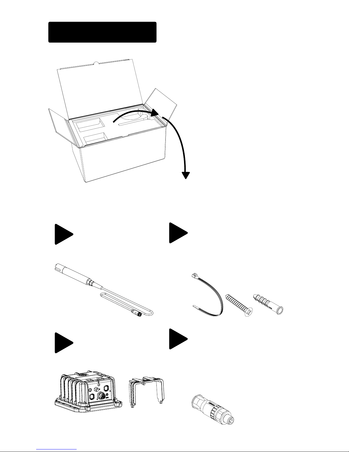
Sensor & Cable
(NOTE: Kit can be
congured for more
than one sensor.)
Wavelet Device &
Protector
Zip Ties, Screws & Anchors
1x
1x
8x2x 8x
4
1x
M8 Male Power Connector
(optional, see page 16)
1x
1x
AYYEKA
Page 4
3
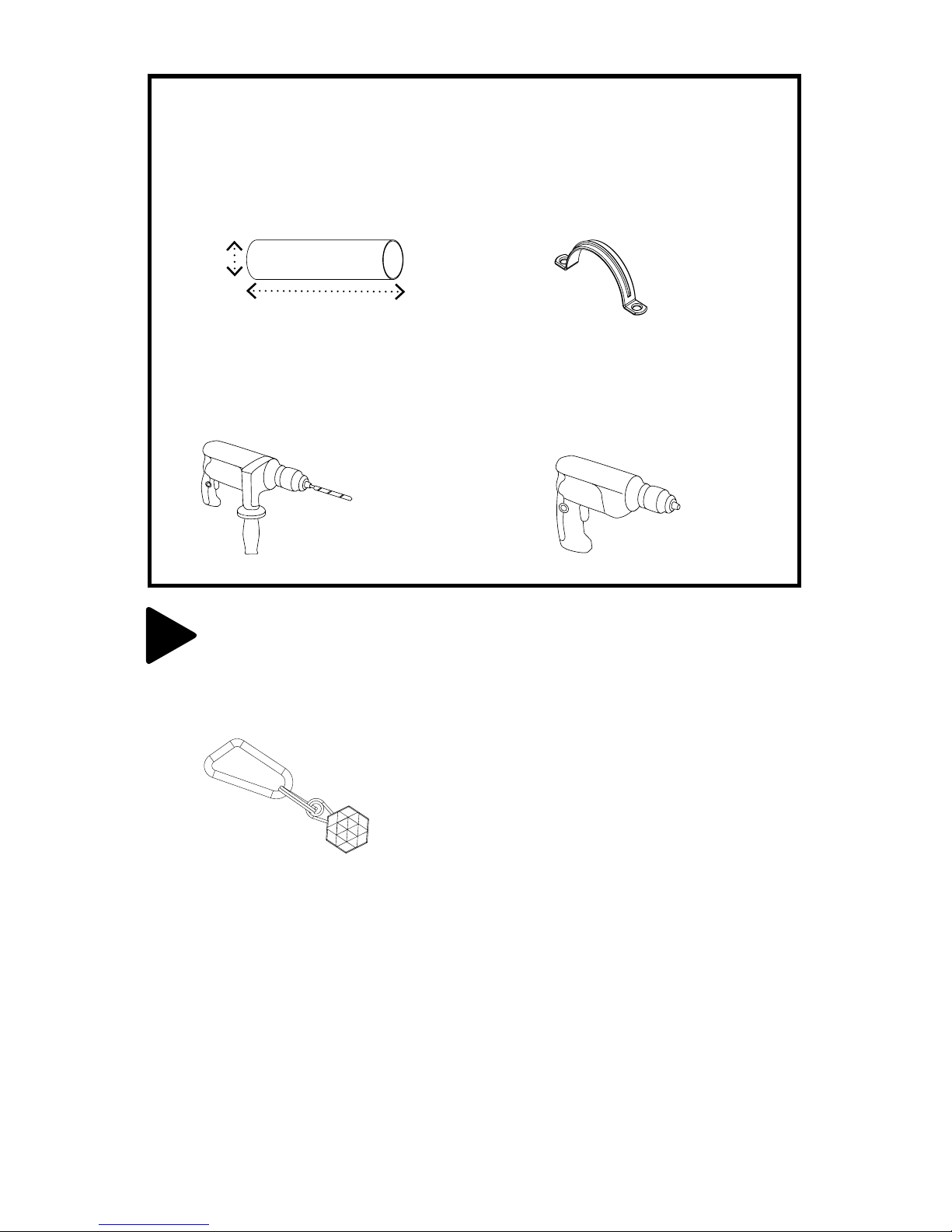
Tools and/or materials required (not included):
2x
1x1x
U-clamps
Electric Screw Driver
PVC pipe
Rotary Hammer
1x12 in.
3 in.
5
1x
Wavelet Activator
Page 5
4
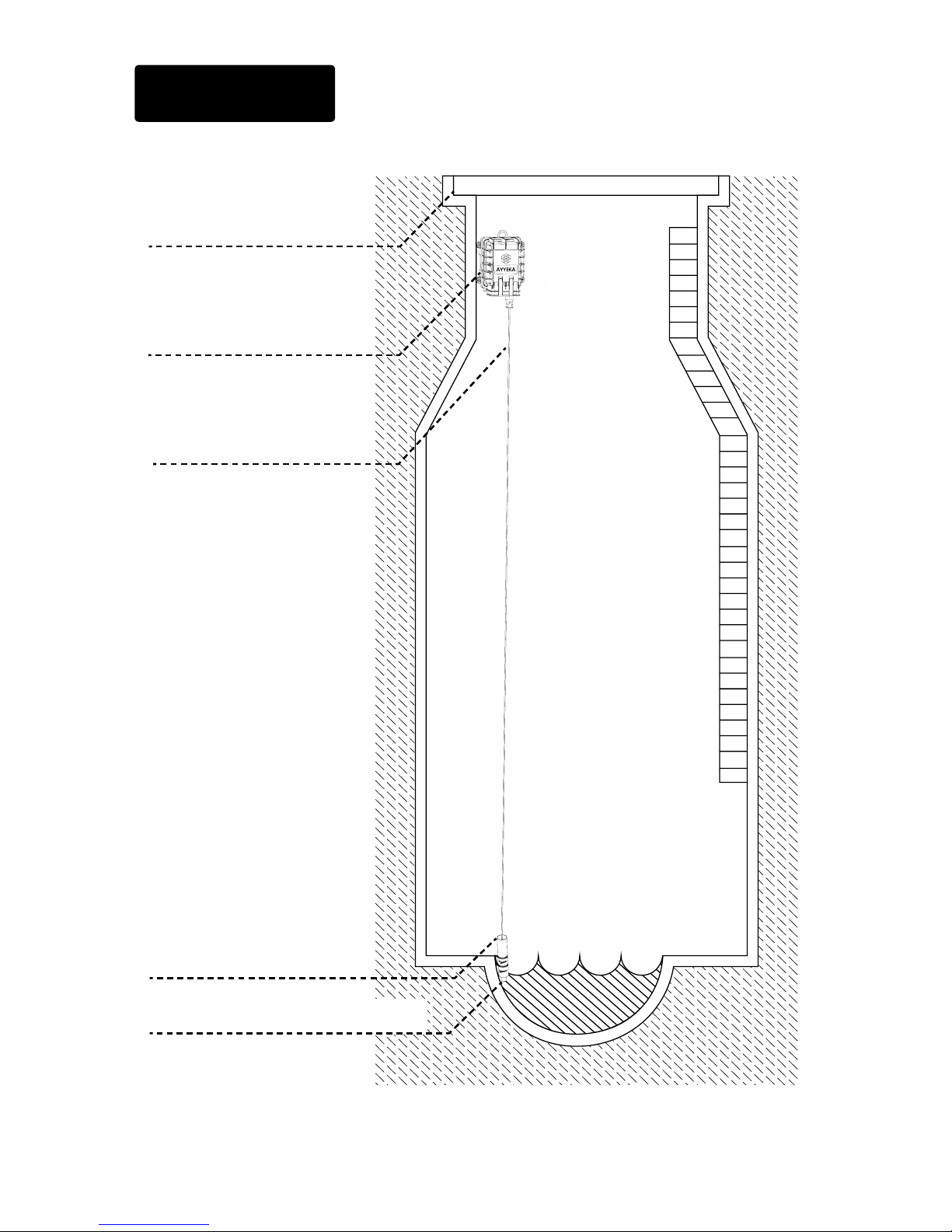
SCHEMATIC
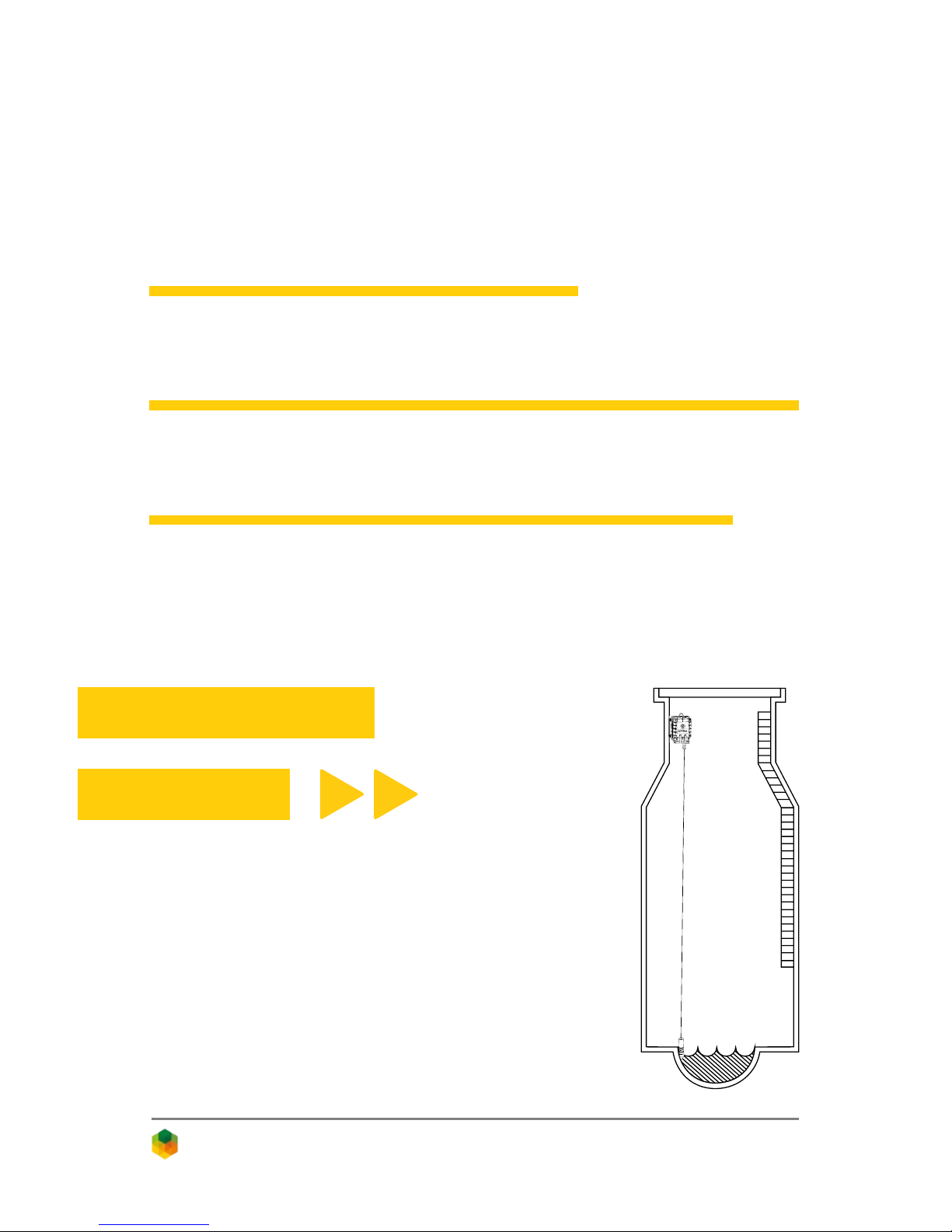
PVC Pipe
Wavelet
Manhole Cover
Sensor Cable
Wastewater Quality Sensor
Page 6
5
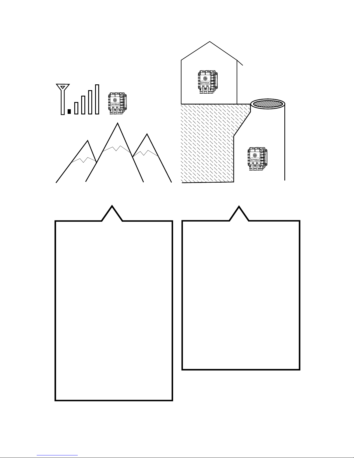
NOTE: Special Installation Locations
WEAK CELLULAR SERVICE
LOCATIONS:
If the Wavelet is installed
in an area with weak
cellular reception, activate
the Wavelet and place in
the intended installation
location with closed doors/
access hatch.
Log in to home.ayyeka.
com to ensure that cellular
signal has been recently
updated in the last few
minutes.
UNDERGROUND/INDOOR
WAVELET INSTALLATIONS:
Before installation, activate
the GPS outside by turning
on the Wavelet (see step 6).
Wait for at least 8 minutes,
then log in to the user
interface at
home.ayyeka.com to
conrm updated location
on the map.
Page 7
6
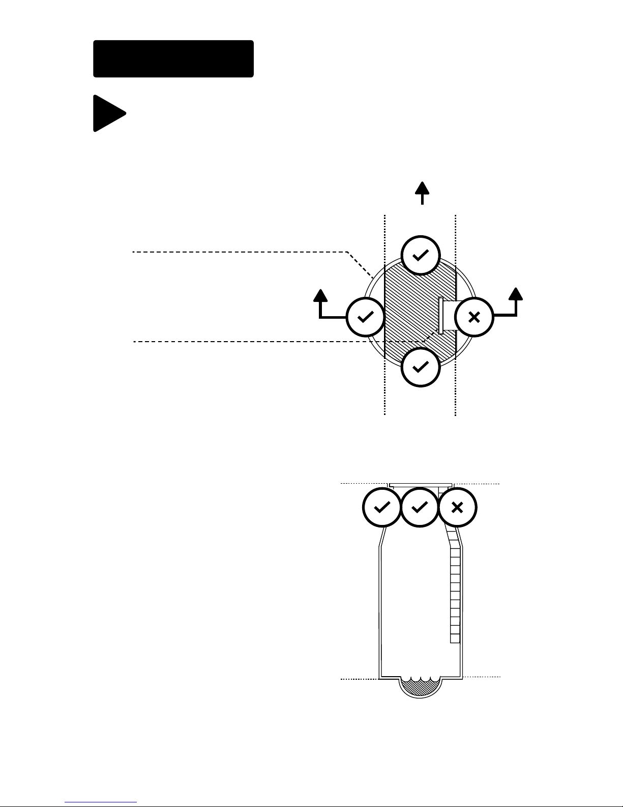
PLAN VIEW
SECTION A-A
AA
Stream
INSTALLATION
Choose proper installation location, such that there will
be adequate clearance after installation to ascend and
descend the ladder.
1
Manhole Opening
Ladder
Page 8
7
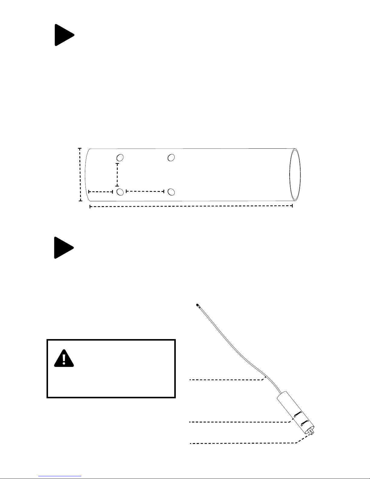
Prepare a section of PVC pipe (recommended dimensions
are 12 inches long by 3 inches in diameter).
Drill two (2) holes approximately two (2) inches from the
edge of the PVC pipe, and leave no more than two (2) inches
of horizontal spacing between the holes.
Then, drill two (2) additional holes approximately three (3)
inches above and vertically aligned with the lower set of
holes.
3 in.
2
12 in.
3 in.
2 in.
2 in.
Using caution not to exert too much force, lace one (1) zip
tie through the upper set of drilled holes in the PVC pipe
and rmly secure the sensor. Lace one (1) additional zip tie
on the lower set of drilled holes to rmly secure the sensor
in the PVC pipe.
3
Wastewater Quality Sensor
PVC Pipe
Cable
CAUTION: Applying
too much force on the
sensor with the zip ties
may cause damage.
Page 9
8
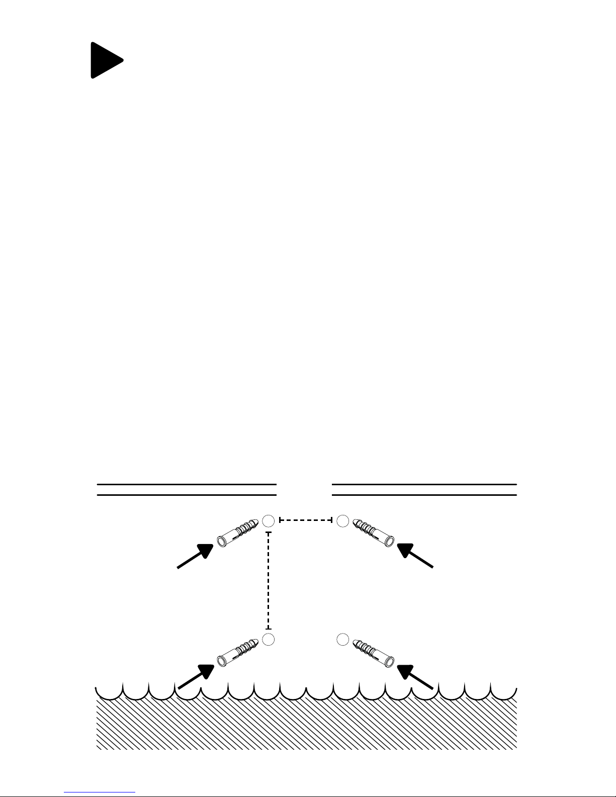
Secure the unattached end of the sensor cable before
descending into the manhole. Choose proper installation
conguration and location above and adjacent to the water
stream, taking into account cable length.
Drill a set of holes for each of the two (2) U-clamps leaving
approximately 4 – 10 inches of vertical spacing between the
clamps with horizontal spacing matching the width of the
U-clamp holes.
Insert anchors into each of the four (4) holes for the
U-clamps.
4 – 10 in.
4
Match
U-clamp
spacing
Page 10
9
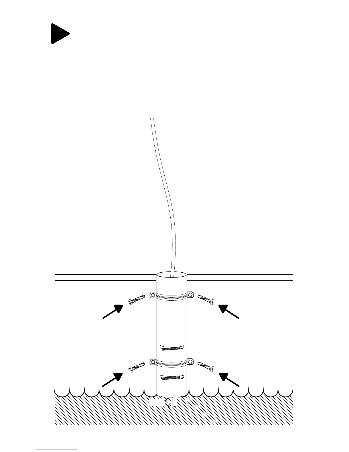
Ensure that the tip of the sensor will be submerged at least
one (1) inch into the stream once the PVC pipe assembly is
clamped to the wall.
Bolt the PVC pipe and sensor apparatus to the wall using
the U-clamps.
5
1 in.
Page 11
10
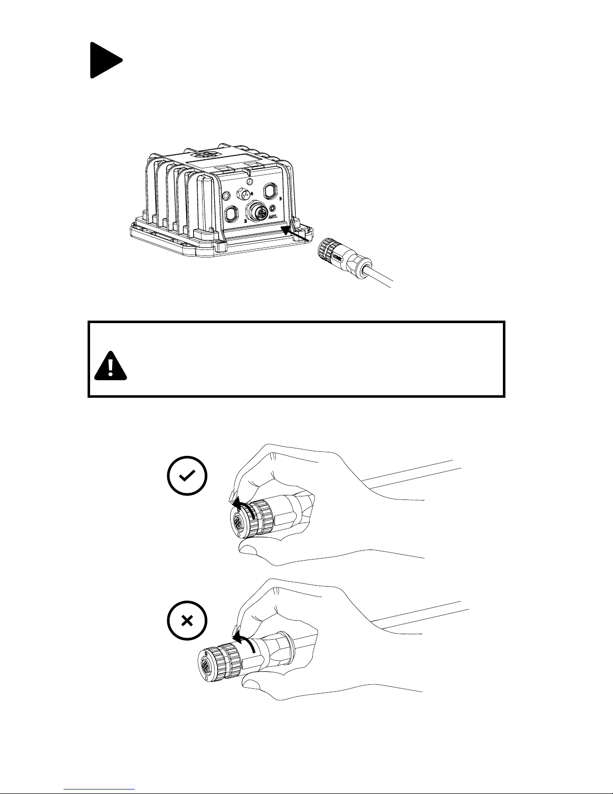
Connect the sensor cable with the connector to the
Wavelet. Turn the adjustable black plastic or silver end piece
to secure the sensor connector to the Wavelet.
6
CAUTION: Do not turn the black plastic hood of the
connector. Turning the black hood will cause the wires to
disconnect, break, and/or damage the connector pins.
TURN HERE
DO NOT
TURN HERE
AYYEKA
Page 12
11
WAVELET ACTIVATION
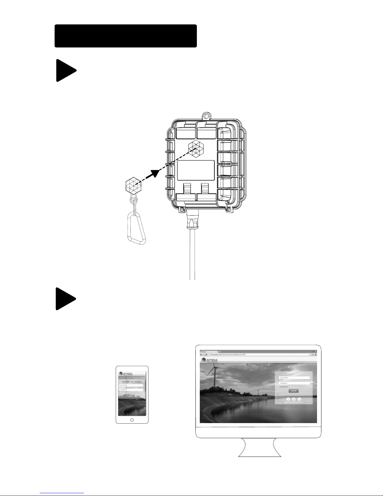
Place the Wavelet Activator on the Ayyeka logo on the
Wavelet front panel for a few seconds. Wavelet will initiate a
10 minute online test mode.
Access the Ayyeka user interface at home.ayyeka.com using
your log-in credentials. Expect data to appear between
10 – 20 minutes after the online test mode is complete.
7
8
AYYEKA
Page 13
12
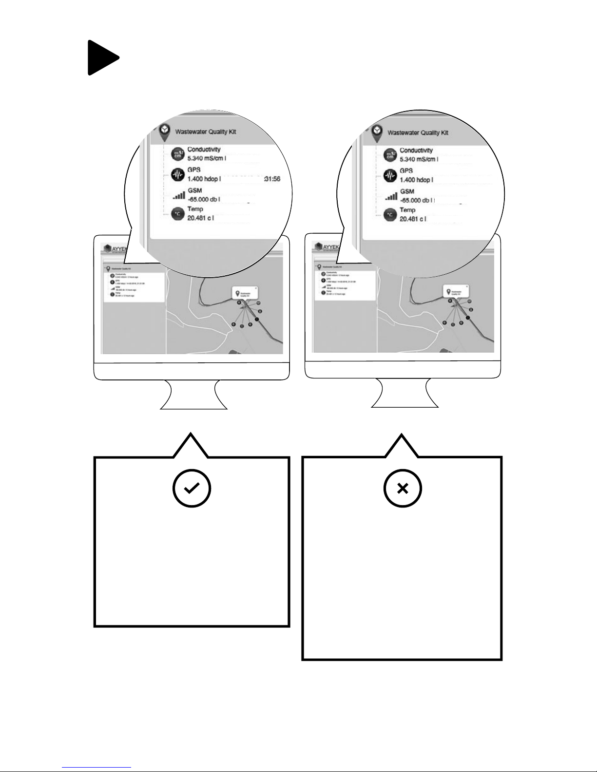
9 The screen display should resemble the following:
24 hours ago
24 hours ago
24 hours ago
24 hours ago
4 minutes ago
4 minutes ago
4 minutes ago
4 minutes ago
If Wavelet is transmitting
properly, you have
completed the installation
successfully and can begin
collecting and viewing your
data!
If data does not transmit
properly, change the
Wavelet installation location
and activate again. If the
problem persists, contact
[email protected]
or +1 (310) 876-8040 for
assistance.
Page 14
13
10
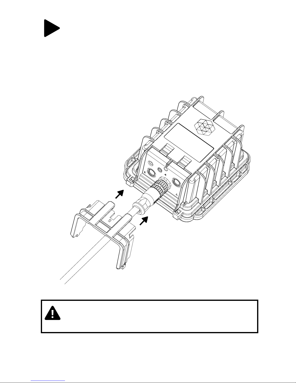
After the Wavelet completes the transmission process, place
the Wavelet protector above the connector ports and secure
the Wavelet protector into the Wavelet enclosure.
AY YEK A
CAUTION: The protector is provided to shield the
connector from tampering or overexposure that could
result in disconnected wiring.
Page 15
14
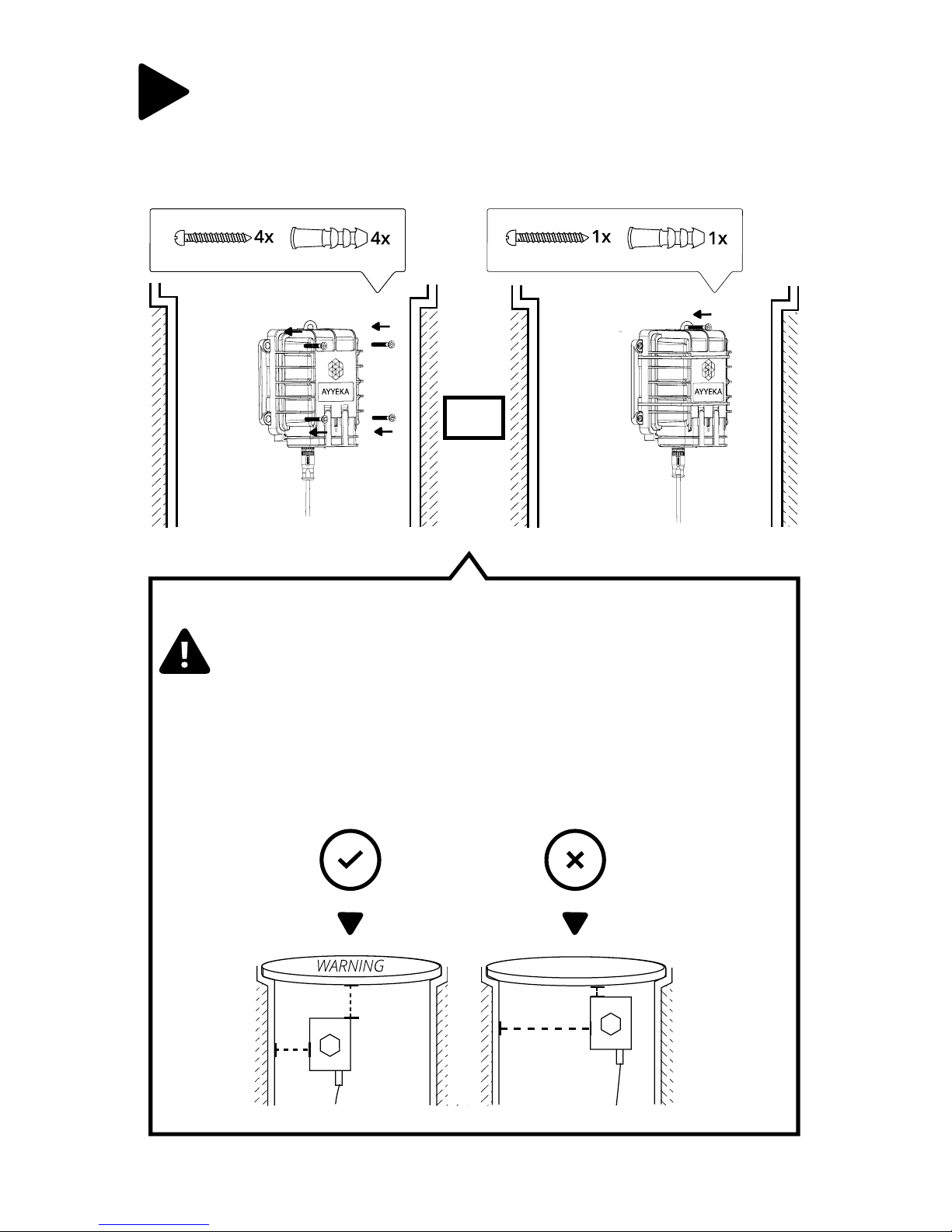
Secure the Wavelet by screwing it into the wall with two (2)
screws and anchors on either side, or with one screw via the
top mounted hanger.
11
CAUTION: Be cautious not to install the Wavelet too
close to the collar of the manhole cover so that upon
removing the cover, it does not damage the Wavelet.
It is recommended to put a label on the visible
surface of the manhole cover warning of sensitive
electrical equipment within.
OR
Page 16
15
YOUR WAVELET
WASTEWATER
QUALITY KIT IS NOW
SUCCESSFULLY INSTALLED!
Page 17
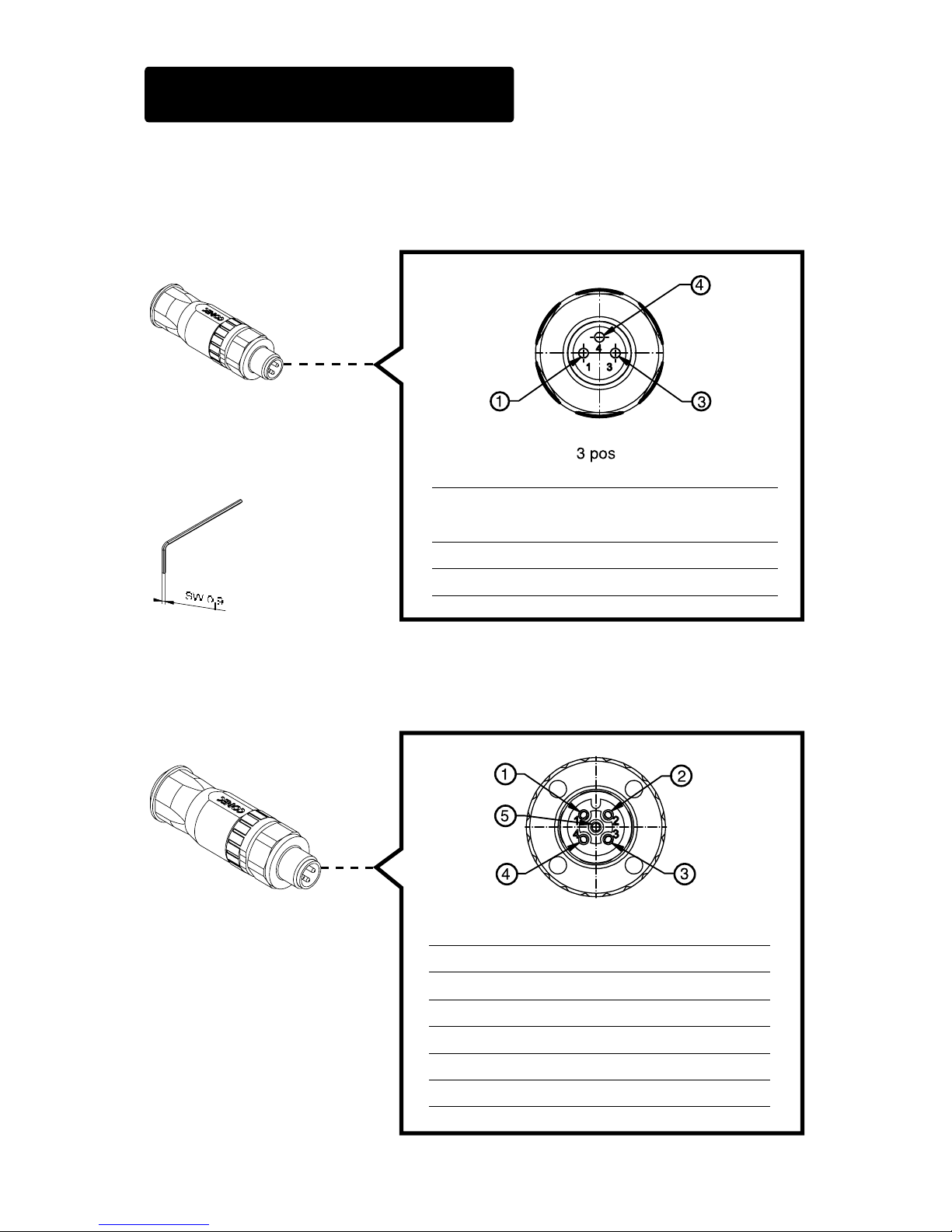
16
Power Connector
Wire To Connect:
Cable Wire Cross
Section Surface Area
0.14 –
0.5 mm
2
Wire Gauge AWG 26-20
Cable Ø Diameter 4 – 5.5 mm
+ Installation Tool
for Wire Termination
(Included)
N.C.
+12V
GND
WIRING INSTRUCTIONS
EXTERNAL POWER:
Conn. Pin Color Signal
1 Green R5485 (B)
2 White R5485 (A)
3 Red +12V
4 Black GND
5 - N.C.
Wire To Connect:
Sensor Connector
B. SENSOR CONNECTOR:
Page 18

www.ayyeka.com
[email protected]
+1 (310) 876-8040
QUESTIONS?
 Loading...