

Page 1
A y r e
K-3x Preamplifier
Owners Manual
Page 2

Page 3
7DEOHRI
Contents
:HOFRPH WR
,QVWDOODWLRQ DQG
2SWLPL]LQJ WKH
1XPEHUV DQG
,Q &DVH RI
6WDWHPHQW RI
$ 3ODFH IRU
Ayre . . . . . . . . . . . . . . . . . . . . . . . . . . . 2
Operation . . . . . . . . . . . . . . . . . . . . . . . . 3
Phono Stage . . . . . . . . . . . . . . . . . . . . . . . 9
Specifications . . . . . . . . . . . . . . . . . . . . . . 13
Trouble . . . . . . . . . . . . . . . . . . . . . . . . 14
Warranty . . . . . . . . . . . . . . . . . . . . . . . . 16
Notes . . . . . . . . . . . . . . . . . . . . . . . . . . 19
Page 4

:HOFRPHWR
Ayre
Please send in your warranty
registration card so we can
stay in contact with you.
The Ayre K-3x offers a significant advance in the musical
performance of audio preamplifiers. The warmth and
immediacy of a live performance are apparent from the first
listening. The combination of superb resolution and a
natural, relaxed quality will draw you into the music, time
and time again. This level of performance has been
implemented using the highest level of workmanship and
materials. Your Ayre K-3x preamplifier will provide a
lifetime of musical enjoyment.
Page 2
Page 5

,QVWDOODWLRQDQG
Operation
The Ayre K-3x is easy to hook up and use. The following
guidelines will ensure that the installation goes smoothly.
/RFDWLRQ
The Ayre K-3x comprises two components - the main
preamplifier and the external power supply. If necessary,
these two pieces can be temporarily separated by your dealer
to facilitate installation into a cabinet.
The preamplifiers power
supply emits a mild hum
field, and should be located
away from other components.
The main unit produces very little heat and can normally be
stacked with other components. However, in certain
situations, hum can be induced into the audio circuitry. In
this case, try separating the components by a few feet (one
meter or so) to isolate the interfering component.
The receiver for the optional infrared remote control is
mounted behind the left-most scallop on the preamplifiers
front panel. Although the transmitters beam will reflect off
of most wall surfaces, a direct line of sight from the
listening position will ensure the maximum range. The
beam will also travel through glass if necessary.
Page 3
Page 6
,QSXWV
When you have a choice, a
balanced connection will offer
slightly higher sound quality
than an unbalanced
connection.
If a tape deck is not installed
in your system, input 4
performs like the other
unbalanced inputs.
If the phono stage is not
installed, input 2 performs
like the other balanced input.
The Ayre K-3x offers two pairs of balanced inputs and two
pairs of unbalanced inputs. Balanced connections are made
via three-pin XLR connectors, while unbalanced
connections are made via RCA jacks. In accordance with the
IEC standard, pin 2 is the positive phase (hot) of the XLR
connectors.
The input connectors on the rear panel are labeled 1
through 4.
If you are connecting a tape deck to your system,
be sure to connect it to input 4.
This will prevent the undesired possibility of a feedback
loop when monitoring a tape recording.
If the optional phono stage is installed, it will
use input 2. Do not connect a line-level source
to this input, as it may damage the phono stage.
Please refer to the section Optimizing the Phono Stage
for more detailed information on connecting your turntable.
Input 1 on the rear panel
corresponds to the top label,
while input 4 corresponds to
the bottom label.
Page 4
,QSXW/DEHOV
The front panel switches can be labeled to reflect the
components in your individual system. The faceplate must
be removed to install custom labels for the selector
switches. Use the supplied 1/8" allen wrench to remove the
four screws visible on the faceplate. Then slide the faceplate
away from the unit, taking care not to scratch the knobs.
Page 7
Remove the old label by using a small object (such as an
allen wrench) to push through the access holes on the rear of
the faceplate. The labels have a self-adhesive backing, and
new ones are simply pressed into place.
2XWSXWV
Both pairs of outputs may be
used simultaneously.
However, please note that the
level of the unbalanced output
will be 6 dB lower than the
balanced output.
2.0 dB Steps
A y r e
1.5 dB Steps
The Ayre K-3x offers one pair of balanced outputs and one
pair of unbalanced outputs.
Please note that the unbalanced outputs invert
absolute polarity.
When using an unbalanced connection between the Ayre
K-3x and your power amplifier, it is suggested that the
speaker cables plus and minus leads be reversed at the
amplifier. This will restore absolute polarity and can
enhance the sense of realism on many recordings.
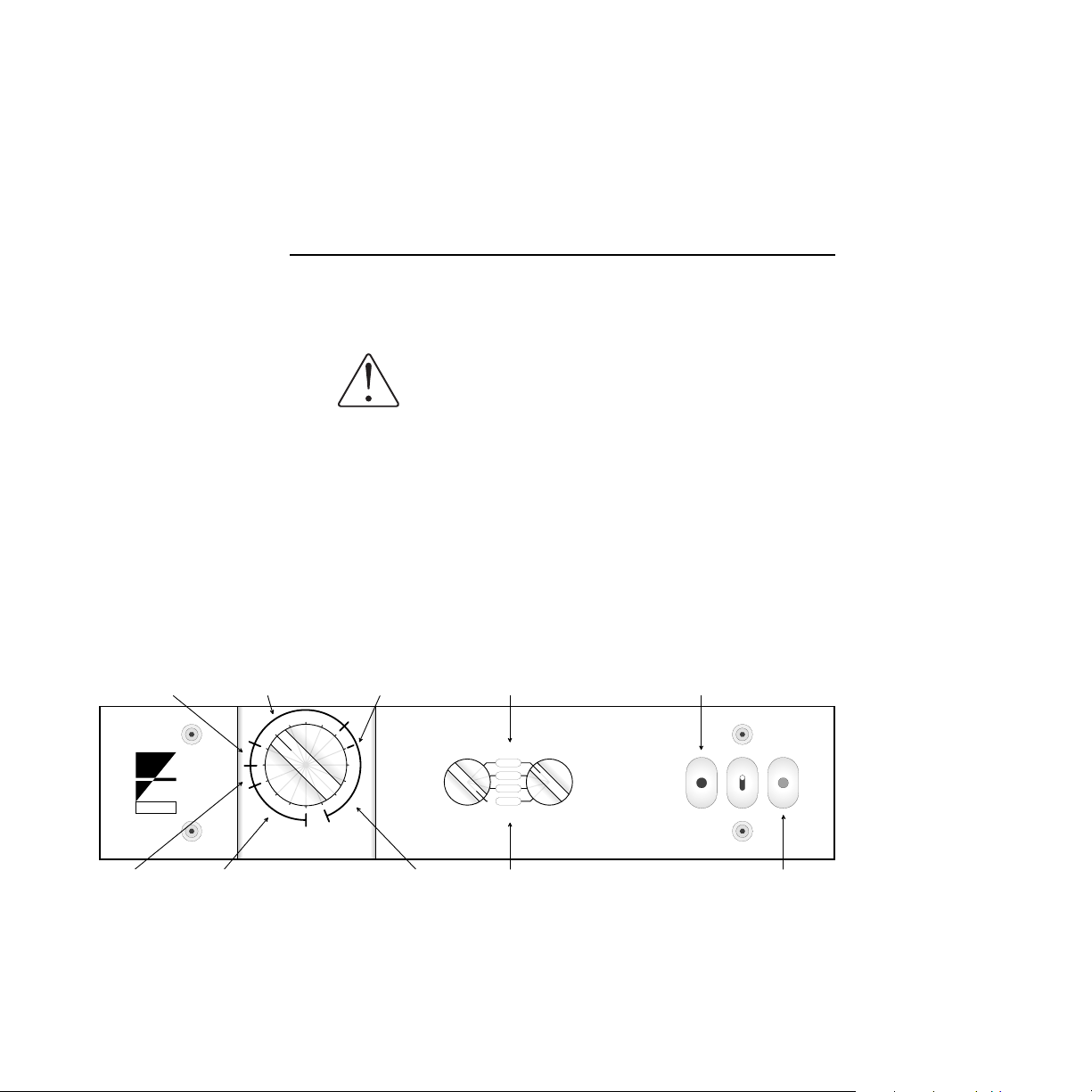
Infrared Remote
Unity Gain
Record
Input #1
Disk
Phono
Video
O f f
Tape
Listen
Control Receiver
Mute
4.0 dB Steps3.0 dB Steps
2.0 dB Steps
Input #4
Status Indicator
Red = Warm-Up
Green = Mute
Blue = Listen
Page 5
Page 8

3RZHULQJWKH8QLW
The Ayre K-3x draws very
little power and is designed to
be left on at all times.
The volume control and the
mute switch may be operated
either by the optional remote
control or the front panel
controls.
The Ayre K-3x features a sophisticated power monitoring
system. When first plugged in to an AC power source, the
front panel indicator light will glow red for approximately
90 seconds. During this time, the outputs are muted and
the mute switch is inoperable.
After the circuitry has stabilized, the indicator light will
change to green, indicating that the unit is ready for play,
though the unit remains muted. When the listener toggles
the mute control, the unit is operational and the indicator
light glows blue.
&RQWUROV
There are four controls on the Ayre K-3x preamplifer - the
volume control, the input selector (Listen), the tape
record selector (Record), and the mute switch. These
controls provide the ideal combination of flexibility and
ease of use.
Page 6
Unlike other products that use conventional volume
controls (potentiometers), the Ayre K-3x uses a mil-spec,
precision stepped attenuator with solid-silver contacts to
provide the ultimate in sound quality. This volume control
features 31 distinct positions, offering precise and
repeatable settings.
The remote control transmitter furnished with the K-3x has
four buttons. The three buttons on the right side of the unit
control the volume and muting functions. The fourth
button on the left side will control the V-1x power
amplifier, should you have one in your system.
Page 9

It is normal to listen with the
volume knob advanced farther
than you may be used to with
other equipment.
The volume control offers 1.5 dB steps over most of its
range, allowing you to exactly select the desired listening
level. To maximize its capabilities, it has been designed so
that the volume knob will be between 1 oclock and 3
oclock for a loud playback level in most systems.
When a surround-sound processor is used, it is sometimes
useful to know the unity-gain volume setting. Since the
gain of the Ayre K-3x line-stage is 16 dB when driving a
power amplifier with balanced inputs, unity gain occurs
when the volume control is eight steps below the maximum
setting (see illustration).
Since the tape record selector
(Record) is controlled
separately from the main
input selector (Listen), it is
possible to listen to one source
while recording from another.
When using the Ayre K-3x
with an unbalanced power
amplifier, note that the
unity-gain volume setting
will now occur when the
volume control is five steps
below the maximum setting.
The tape record selector (Record) controls which source
component is connected to the tape output jacks. It is
recommended that the tape record selector be switched to
the Off position except when making a recording. This
will isolate the tape decks circuitry from the preamplifier,
providing the highest level of sound quality when listening.
8QEDODQFHG3RZHU$PSOLILHUV
Unbalanced power amplifiers with single-ended inputs only
utilize one-half of the Ayre K-3xs balanced output signal.
The result is a 6 dB gain reduction, requiring that the
volume control be further advanced for an equivalent
listening level. However, certain systems may have
insufficient gain to produce a satisfying listening level, even
with the volume control turned fully up.
If required, the gain of the line stage can be increased 6 dB
to compensate for this loss. Please contact your authorized
Ayre dealer or the factory for information on this procedure.
(It is not recommended to increase the gain of the Ayre
K-3x when using a balanced amplifier, as the level of the
lowest volume setting may be too loud.)
Page 7
Page 10

%UHDN,Q
Please note that the optional
phono stage utilizes
additional circuitry and will
require its own break-in
period, achieved by playing
records.
A break-in period is required to achieve the maximum sonic
potential of the Ayre K-3x due to the manufacturing
processes used in the capacitors, circuit board material, and
wires. This normally requires between 100 and 500 hours
of playing time.
Page 8
Page 11

2SWLPL]LQJWKH
Phono Stage
The optional phono stage in the Ayre K-3x offers the
ultimate in flexibility and performance for all types of
phono cartridges.
&RQQHFWLRQV
Do not connect a line-level source to the phono
input as damage to the phono stage may result.
The balanced phono
configuration yields
maximum sonic performance
with minimum hum or
interference.
As the phono cartridge is an inherently balanced device, the
Ayre K-3x phono stage is also balanced, using XLR jacks at
the input. Since most tone arms and/or turntables are not
equipped with XLR connectors, there are two choices for
making the proper connection:
1) Use an RCA-to-XLR adapter. This often may be the
easiest solution to implement, but introduces an extra set of
contacts into the signal path. In addition, this converts the
balanced source into an unbalanced input and causes a
slight loss of sound quality.
2) Use dedicated cables with XLR connectors at the
preamplifier end and the appropriate connector (RCA or
DIN, depending on the particular installation) at the
turntable end. This is the preferred solution and offers the
highest level of sound quality.
Page 9
Page 12

Ayre manufactures both adapters and dedicated cables.
These high-performance custom designs are available from
your authorized Ayre dealer. In addition, termination
instructions are available if you wish to reterminate your
current cables. Please contact the factory for further details,
or refer to our web site at
www.ayre.com
.
*DLQDQG/RDGLQJ
The gain is factory-set to 50
dB, which is well suited to
most modern phono cartridges.
It is recommended that the
loading not be changed from
50 kΩ when using a
moving-magnet cartridge.
The gain of the phono stage is adjustable in 10 dB steps
from 40 dB to 60 dB, accommodating virtually any
cartridge made. Recommended gain settings are as follows:
&DUWULGJH2XWSXW 3KRQR*DLQ *DLQ5HVLVWRU
Less than 1.0 mV . . . . . 60 dB . . . . . . 20Ω
1.0 mV to 3.0 mV . . . . 50 dB . . . . . . 150Ω
Greater than 3.0 mV . . . 40 dB . . . . . . 500Ω
These are guidelines only. Variations from these settings are
perfectly acceptable.
The default cartridge load is 50 kΩ, which is suitable for
almost all cartridges. However, many moving-coil
cartridges yield better performance if they are loaded with a
lower impedance.
Usually, a lower load impedance results in a more focused
soundstage, with greater image solidity and less apparent
distortion. A higher load impedance will give a more open
sound, with greater air and life. The final value must be
chosen by ear to give the best sound in your particular
system.
Page 10
Page 13

3KRQR*DLQ5HVLVWRUV
&DUWULGJH/RDGLQJ5HVLVWRUV
)URQWRI3UHDPSOLILHU
The phono gain and loading can be adjusted by your
authorized Ayre dealer. However, for those owners that
prefer to perform this task themselves, the following tools
are required:
5/64" allen wrench (supplied)
Small screwdriver - 0.080" to 0.100" (2.0 to 2.5 mm)
Tweezers, or small needle-nose pliers
Changing the phono gain and loading resistors
is comparable in complexity to installing a
phono cartridge. Do not perform this task
yourself unless you are completely comfortable
with it.
Page 11
Page 14

Disconnect the preamplifiers power supply
from the AC power before working on the unit.
To adjust the gain or loading of the phono stage, use the
supplied 5/64" allen wrench to remove the six screws that
secure the top cover. The phono board is horizontally
mounted and located toward the right side of the chassis.
The phono board has two small brown terminal strips per
channel used to connect small metal-film resistors. The
terminal strips towards the front of the preamplifier is used
to adjust the gain of the phono stage, while the terminal
strip towards the rear of the unit accepts the loading
resistor. The resistor leads are clamped by the two screws in
the terminal strip, forming a gas-tight connection for
optimum sound quality.
To remove the installed resistors, use a small flat-bladed
screwdriver to loosen the two screws in the terminal strip
until the screw heads are flush with the top surface of the
terminal strip. Gently remove the resistor with a pair of
tweezers or small needle-nose pliers.
Page 12
To install the new resistors, use the tweezers or small
needle-nose pliers to insert the two leads into the holes on
the side of the terminal strip. Orientation is not important
the resistor can be installed either way. Use the
flat-bladed screwdriver to gently snug the two screws down.
Do not overtighten them.
Do not operate the preamplifier without the
gain-adjusting resistors installed.
Replace the top cover, reinstalling the six screws with the
5/64" allen wrench.
Page 15

1XPEHUVDQG
Specifications
Gain - Line
Gain - Phono
Input Impedance - Line
Input Impedance - Phono
Output Impedance
Power Consumption
Dimensions
16 dB to balanced outputs, 10 dB to unbalanced outputs.
Other values available upon request.
Adjustable 40 dB, 50 dB (factory setting), 60 dB
10 kΩ (each phase)
Adjustable 50 kΩ (factory setting)
100 Ω, 250 Ω, 500 Ω, 1000 Ω loading resistors supplied.
Other values available upon request.
300 Ω (each phase)
30 watts
18" W x 11" D x 3-3/4" H
(46cm x 28cm x 9.5cm) Main Unit
10" W x 8" D x 3" H
(25cm x 20cm x 7.6cm) Power Supply
Weight
25 pounds (11.5 kg) Complete Unit
Page 13
Page 16

,Q&DVHRI
Trouble
Should the Ayre K-3x preamplifier ever fail to operate
properly, please check the following:
Symptom: Remote control not
working.
Symptom: No sound, and the
status indicator is glowing
red.
Symptom: Status indicator
lamp not lit.
Check the batteries located in the remote control.
If the AC line voltage drops below 80% of normal
(brown-out), the outputs will mute and the indicator light
will glow red. After the line voltage returns to normal, the
initial power-up cycle will begin again.
Should the AC line lose power, the preamplifiers outputs
are immediately muted. This avoids any loudspeaker
damage due to thumps or pops.
1) Be sure that the power supply unit is connected to a
working AC outlet.
2) Check the AC line fuse.
To check the fuse, locate the rectangular fuse holder
mounted on the rear panel of the power supply. Press
downwards on the top edge, then pull outward. There are
two fuses mounted in the fuse holder. The inner one is the
operating fuse, and the outer one is a spare.
Page 14
Page 17

The condition of the fuse can be determined by a visual
inspection, although an ohm-meter provides a more reliable
method. If in doubt, substitute the spare for the operating
fuse. If the spare fuse also blows, do not attempt further
repairs.
Always use the correct fuse!
/LQH9ROWDJH )XVH5DWLQJ[7LPH'HOD\
100 V . . . . . . . . . . . 1 A
120 V . . . . . . . . . . . 1 A
230 V . . . . . . . . . 500 mA
There are no user-serviceable parts in the Ayre K-3x. If the
preamplifier still does not operate, bring the unit to your
dealer for assistance.
Do not remove the power supply cover.
Hazardous voltages may exist inside the unit.
Page 15
Page 18

6WDWHPHQWRI
Warranty
Please take the time to fill out
and return the enclosed
warranty registration card.
Your Ayre K-3x preamplifier is warranted against defects in
workmanship and materials for a period of five years from
the date of purchase. This warranty is transferable to
subsequent purchasers within the original five-year period.
All warranty claims must be made through an authorized
Ayre dealer or distributor. A complete statement of
warranty is given below.
:DUUDQW\6WDWHPHQW
1. Ayre Acoustics, Inc. (Ayre) warrants the materials and
workmanship of this product for a period of five years from
date of first purchase. If any defects are found in the
materials or workmanship of this Ayre product within the
warranty period, the unit will be repaired or replaced by
Ayre or its authorized agent.
2. Purchaser must return the product, packed in the
original shipping carton, freight prepaid to:
Page 16
Ayre Acoustics, Inc.
2300-B Central Avenue
Boulder, Colorado 80301
Page 19

3. Ayre reserves the right to inspect any product that is the
subject of any warranty claim prior to repairing or replacing
it. Final determination of warranty coverage lies solely with
Ayre. Out-of-warranty claims will be billed for labor,
materials, return freight, and insurance as required. Any
product for which a warranty claim is accepted will be
returned to the purchaser and the cost of shipping and
insurance will be factory prepaid within the boundaries of
the USA. Units to be shipped outside of the USA will be
shipped freight collect only. This warranty gives specific
legal rights. The purchaser also has implied warranty
rights, and may also have other rights which vary from state
to state.
4. Ayre strives to manufacture the finest possible
equipment, and therefore reserves the right to make
improvements on its products, without necessarily
assuming an obligation to retrofit such changes upon its
previously manufactured models.
5. The above warranty is the sole warranty given by Ayre,
and is in lieu of all other warranties. All implied warranties,
including warranties of merchantability or fitness for any
particular purpose shall be strictly limited in duration to
five years from the date of original purchase, and upon
expiration of the warranty period (five years), Ayre shall
have no further obligation of any kind, whether express or
implied. Further, Ayre shall in no event be obligated for
any incidental or consequential damages as a result of any
defect or any warranty claim, whether express or implied.
Some states do not allow exclusion or limitations of
incidental or consequential damages or limitations on how
long implied warranties last, so the above limitation and
exclusions may not apply to you.
Page 17
Page 20

6. Ayre does not authorize any third party, including any
dealer or sales representative to assume any liability of Ayre
or make any warranty for Ayre. The unit must not have
been altered or improperly serviced. The serial number on
the unit must not have been altered or removed.
7. Warranty registration cards must be completed and
mailed to Ayre within 30 days of purchase. Ayre may, at its
option, require from the purchaser valid proof of purchase
(dated copy or photocopy of dealers original invoice).
Page 18
Page 21

$3ODFHIRU
Notes
Page 19
Page 22

Revision 1.2
Page 23

Page 24

Ayre Acoustics, Incorporated
2300-B Central Avenue
Boulder, Colorado 80301
303 442.7300
www.ayre.com
 Loading...