

Page 1
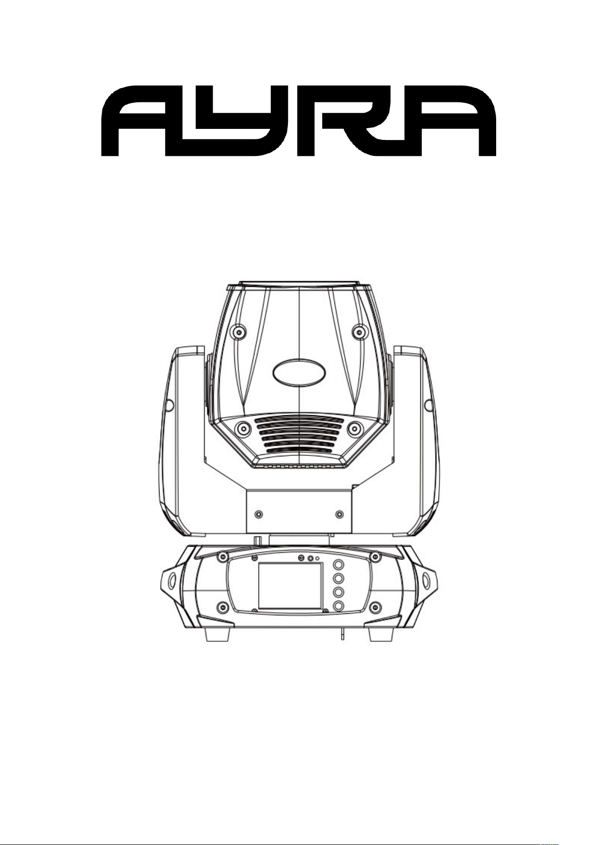
Vision 150 Wash
150W LED Wash Moving Head
User Manual
The information included in this user manual is subject to change at any time and without notification:
Version: 1.1 Date & Author Initials: 09-02-2022 RV Revision Date & Author Initials: -
Page 2

Introduction
Thanks for purchasing the Ayra Vision 150 Wash. This compact moving head offers a versatile array of
features so you can get the best results at any event. This user manual contains all the information you need
to know before using the unit.
Before unpacking the box, we recommend reading this user manual thoroughly to ensure that you are
familiar with all of the features and functions the Vision 150 Wash has to offer. When unpacking the box,
please make sure that all of the components and accessories listed below have been included. If the device
does not function as it should, unplug any connected cables before contacting your local retailer for further
advice.
Box contents:
- Vision 150 Wash LED moving head
- Quick-lock suspension bracket
- Locking blue power plug to Schuko power cable
- Basic DMX connecting cable for testing
- Safety-cable with carabiner hook
Inspection of the Device & Included Accessories
If the device or any of the included accessories have been damaged or rendered defective in transit, please
contact your local retailer for further advice.
Please note: The products seen in the images included in this manual may differ slightly from the actual
products.
The information included in this user manual is subject to change at any time and without notification:
Version: 1.1 Date & Author Initials: 09-02-2022 RV Revision Date & Author Initials: -
Page 3
Safety Instructions
Every person involved with the installation, operation and maintenance of this device must:
- Be qualified.
- Be skilled.
- Have read the instructions included in this user manual.
- Be sure that neither the device nor the included accessories are damaged. Should the device or the
included accessories be damaged, please contact your retailer for further advice.
- Ensure that the device is in good working condition and is safe to operate. Please follow the advice and
instructions as they are described in this user manual.
Damage caused by misuse and/or modifications made to the device are not covered by the warranty.
This device does not contain any parts that can be repaired or replaced by the user. Should maintenance or
repairs be necessary, they must be carried out by a qualified technician.
The light source of the device cannot be replaced. In the event that the light source fails, the entire device
will need to be replaced.
Important Health & Safety Information:
- Do not remove any labels or stickers from this device.
- Do not leave any cables lying around where they are in danger of causing a tripping hazard.
- The housing of this device must not be opened and any hardware or software that may be present must not
be modified.
- For optimal performance, any inputs should not be fed with a signal higher than necessary.
- The device must only be used indoors; contact with water, rain and moisture must always be avoided. Do
not place any objects containing liquid on top of the device.
- Remove the device from any nearby flames or heat sources; do not place it near flammable fluids, gases or
The information included in this user manual is subject to change at any time and without notification:
Version: 1.1 Date & Author Initials: 09-02-2022 RV Revision Date & Author Initials: -
WARNING!
Keep this device away from moisture, water and rain to prevent any danger of electric shocks!
WARNING!
This device must only be connected to a power socket that matches the specified mains voltage.
If this device is connected to a power socket with a different voltage, it may cause permanent
damage or lead to harmful effects including fire hazards or electric shocks.
WARNING!
Always take care when operating this device. Avoid touching any external or internal wiring
when live as they may cause harmful electric shocks!
Page 4
objects.
- Disconnect this device from a power source if it is not being used for a long period of time, if maintenance is
required, or if it needs to be cleaned.
– Do not pull or tug on any cables to remove plugs as this may cause damage.
- Do not use any cables other than those specified in this manual. Do not use defective cables. Please
contact your retailer if the included or specified cables do not function properly with this device.
- Only ever power this device via a stable AC mains power socket.
- Only power this device using a grounded power socket.
- In the event that the device is exposed to extreme temperature changes (e.g. transported from a cold
outdoor environment into a warm indoor environment), it must not be turned on until it has reached room
temperature. This is necessary to prevent moisture (condensation) from forming inside the device, which
may cause electric shocks.
Storage & Transport:
- This device is designed for mobile use and can be transported in its original packaging or in a flight case
with a foam-lined interior as long as it is well protected against shocks and impact.
- This device has not been designed for continuous (24/7) use. Regularly switching the device off will not
affect the expected lifespan of the device. Always switch off and unplug the device when it is not in use.
– When the device is not in use for long periods of time, always disconnect the device from the mains power
and store it in a dust free environment.
– Do not expose the device to extreme temperature shifts.
Housing:
- Frequently inspect the housing of the device and always just before use. Avoid operating the device if any
large dents or cracks are found in the housing, or if screws are missing. Do not use the device if the housing
is not in good condition. Contact your local retailer or a qualified technician if you are unsure about the state
of the device.
- Check the device and screws for any corrosion. If any corrosion is found, do not use the device. Contact
your retailer or a qualified technician if the screws or housing show any signs of corrosion.
- Ensure that every power and signal socket is securely fitted. Do not use the device if any of the sockets are
not secure.
- Avoid the build up of any dust and dirt. Clean the device once a month by disconnecting it
from the power supply and wiping it down with a dry or slightly moist cloth. If the device is
used frequently, the device should also be cleaned more frequently.
Symbol Explanation:
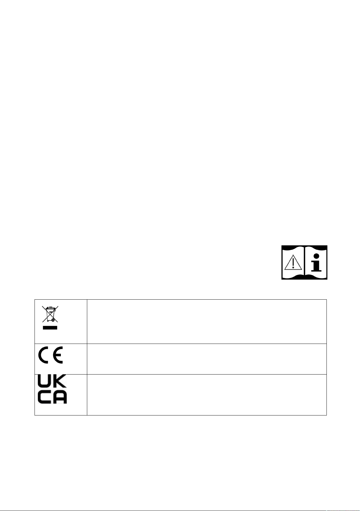
WEEE: Ensure that this device is disposed of properly. This product falls under the WEEE
(Waste Electrical and Electronic Equipment) directive. The requirements of this directive apply to
all manufacturers and producers of electronic devices in the EU. Do not throw this product away
with normal refuse. Please contact your local authority for more information about how to recycle
and dispose of these products in your region. By recycling this product in the proper manner, we
can work together to ensure that we can continue to enjoy these kinds of products and still
protect the environment as much as possible.
CE: The CE logo indicates that this product meets the European norms and requirements to
which it must legally conform.
UKCA: The UKCA mark indicates that this product conforms to the directives and standards that
this product is legally required to comply with in the United Kingdom.
The information included in this user manual is subject to change at any time and without notification:
Version: 1.1 Date & Author Initials: 09-02-2022 RV Revision Date & Author Initials: -
Page 5
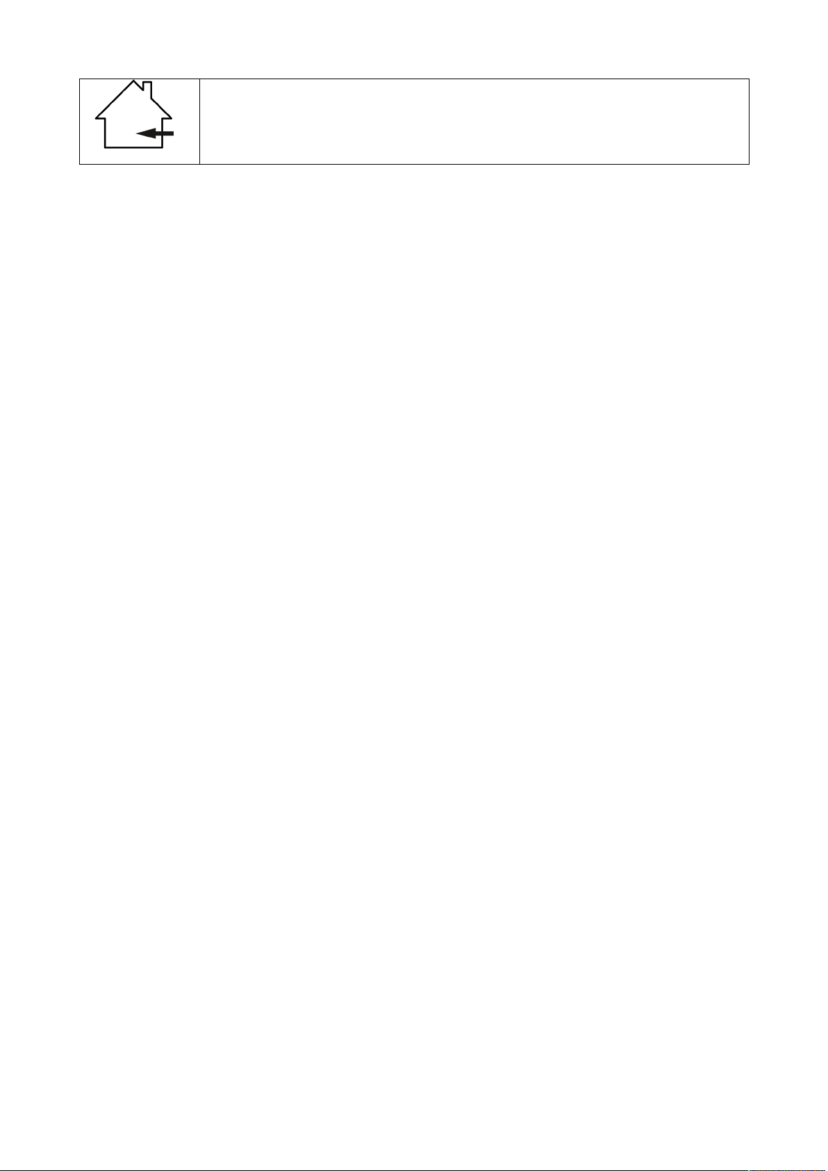
For indoor use only: This product was designed for indoor use only. The maximum
environmental temperature must not exceed 40 degrees Celsius (104 degrees Fahrenheit).
Contact:
Ayra Professional Lighting Products
Verrijn Stuartweg 18
4462 GE Goes
The Netherlands
This is a correspondence address only. Please do not send any physical products to this address.
If you need to send a product for repairs or for a refund, please contact your retailer for an RMA request
(Return Merchandise Authorisation)
The information included in this user manual is subject to change at any time and without notification:
Version: 1.1 Date & Author Initials: 09-02-2022 RV Revision Date & Author Initials: -
Page 6
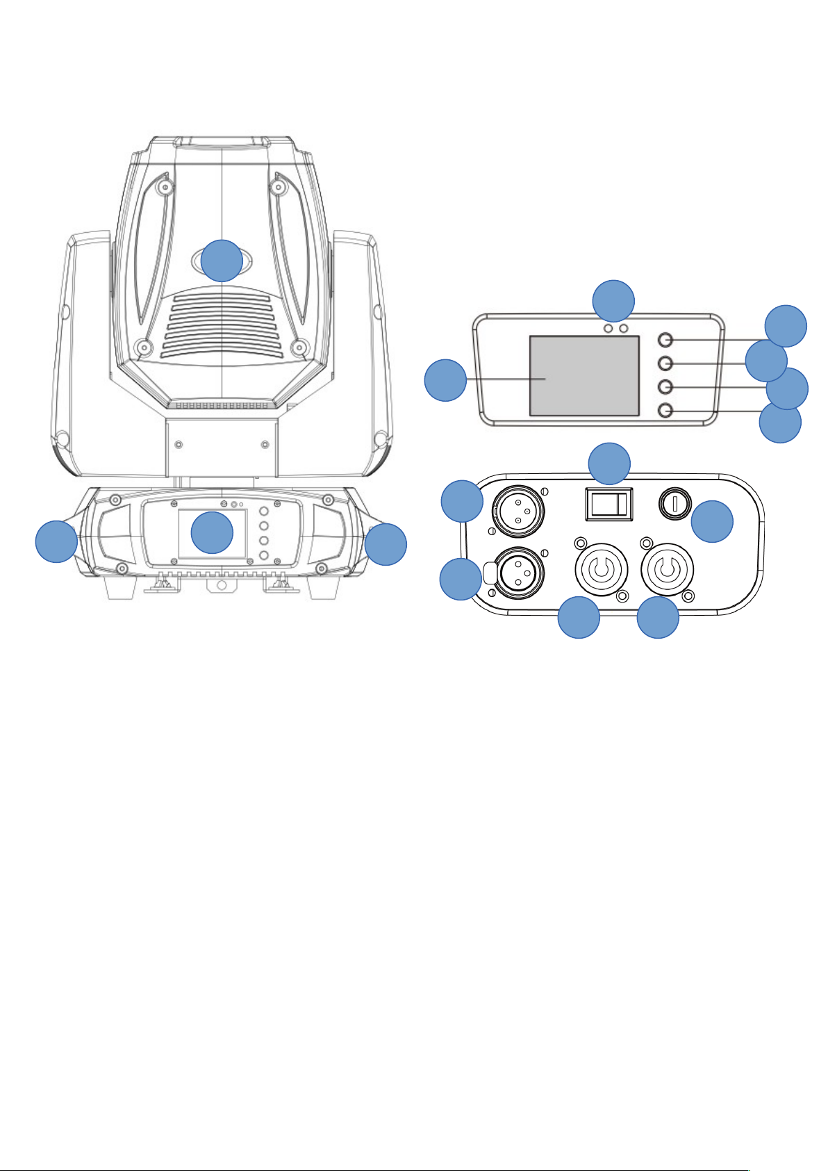
Overview
1. Moving head with light output via lens
2. Display with menu buttons
3. Handle
4. Power output (link output) via white locking power socket
5. Power input via blue locking power socket
6. Fuse compartment for internal fuse (20mm glass, …)
7. On/Off switch
8. 3-pin F-XLR for DMX output/link to chained fixture
9. 3-pin M-XLR for DMX input from DMX controller
10. Menu button: MENU
11. Menu button: UP
12. Menu button: DOWN
13. Menu button: ENTER
14. LED indicators
Base:
- Quick-lock suspension bracket mounting point (for suspended installation)
- Mounting eyelet for securing safety cable (for suspended installation)
A full explanation of these functions is included later in this manual, including illustrations.
The information included in this user manual is subject to change at any time and without notification:
Version: 1.1 Date & Author Initials: 09-02-2022 RV Revision Date & Author Initials: -
1
14
10
11
2
7
9
6
3
2
3
12
13
8
5 4
Page 7

Operation & Installation
To test the device after unpacking it, make sure it is placed on a flat and stable surface far away from any
other objects that may hinder the moving head of the device.
Activate the device by plugging it into a nearby power socket and flipping the power switch into the On
position. The device will now power up.
During the start-up process, the device cannot be controlled. Once the start-up process is complete, the
device will jump to the last-used mode. Now the operating mode and other settings can be changed via the
menu display and buttons.
During the start-up process, all of the motors (for movement and for applying effects to the light beam) are
calibrated. This brings all motors back to zero - so to a starting position. During this process, the device may
appear to stutter, but this is common with a unit of this type.
When a DMX signal is detected, the device shall automatically jump to DMX mode and the last-used DMX
address will be displayed. If the device is being used for the first time, the DMX address 001 will be
displayed. The DMX address can be changed via the menu display and buttons.
Via the menu display and buttons, the functions and settings of the device can be changed. Using the ‘Enter’
button, you can select a function or confirm any changes. Using the ‘Up’ and ‘Down’ buttons, the values of
various functions can be changed, and using the ‘Menu’ button, you can return to the manu menu.
The menu includes the following options and functions:
Main Menu Sub Menu Function Settings & Values
Function
Mode
DMX Address
Setting the DMX address. The DMX channel
value dictates the DMX command channel.
A001 - AXXX
Channel Mode DMX-channel mode
CH12 (12-channels)
CH14 (14-channels)
Auto Run /
Sound Control
Auto Run
Plays back one of the built-in shows at a speed
set by the user. Select master or slave mode.
Ensure smooth performance by setting the
speed and movement separately.
Sound Control
Plays back one of the built-in shows in time to
any music or sound detected by the built-in
microphone. Here the tempo of the detected
sound determines the playback speed.
Show 1 – 9
State: Master / Alone
Auto Run (on/off)
Music Run (on/off)
Step Time: 1 – 10*
Scan Speed: 1 – 10*
*Auto mode only
Option Reset Default Restore factory settings. Yes / No
Signal Set
DMX signal input method.
Please note: At the moment of writing, this unit
only supports a standard wired DMX connection
via a cable. It is possible that future updates and
extensions will expand functionality.
Wire (default)
Wireless DMX input
(DMX via wireless receiver)
ACT WDMX & OUT
(DMX via wireless receiver
and wire output)
Pan / Tilt
Pan/tilt inversion and pan and tilt range limit
settings. Pan controls left and right movements.
Tilt controls up and down movements.
Reverse Pan (On / Off)
Reverse Tilt (On / Off)
Select Pan (630 / 540 / 360)
Select Tilt (270 / 180 / 90)
UI SET User Interface settings, including:
Microphone sensitivity
DMX signal mode. When enabled, the device
Mic Sensitivity (0 – 99%)
OFF signal mode (ON /
The information included in this user manual is subject to change at any time and without notification:
Version: 1.1 Date & Author Initials: 09-02-2022 RV Revision Date & Author Initials: -
Page 8

will switch to Blackout mode in the event of
DMX signal-loss.
Limit mode, limits the vertical and/or horizontal
movement of the fixture depending on physical
positioning in the room (such as left + right in
the corner of the room)
OFF)
Limit mode: Centre / Right /
Left / Off
System
Information
Temperature Current operation temperature of unit.
Temperature displayed in
degrees Celsius (not
adjustable)
Software Version Current software version of device.
Current software version
(not adjustable)
Manual
Control
Reset
Total Reset – completely reset device
Pan / Tilt reset – Reset pan / tilt
Total Reset
Pan / Tilt reset
Channel
Manual control over all set channels. Here, all
functions can be set manually, without the need
for any external control equipment.
When manual mode is active, the current
settings remain active as long as the user does
not return to the main menu.
When this mode is activated, the current setting
values are applied. The values can be adjusted
and saved, but as soon as the user returns to
the main menu, the values will expire.
Pan
Pan Fine
Tilt
Tilt Fine
Move Speed
Strobe
Dimmer
Red
Green
Blue
White
Color_Temp1
Color_Temp2
Advanced
Channel
Calibration
Effect wheel calibration options.
Please note: The motors are factory calibrated.
Adjusting the calibration can lead to slight visual
differences when multiple units are chained and
synchronised.
During normal operation, it is not possible to
calibrate the motors of this unit. Recalibration
will not solve any issues, but will only return the
motor to the starting position.
To make calibration adjustments, the following
access code is required: 088.
Pan
Tilt
Bonus: Display Flip function
This hidden function is commonly used when the unit is suspended. By holding down the UP and DOWN
buttons for three seconds, the display will be vertically mirrored (flipped upside down), making it easier to
read when the unit is in a suspended position.
The information included in this user manual is subject to change at any time and without notification:
Version: 1.1 Date & Author Initials: 09-02-2022 RV Revision Date & Author Initials: -
Page 9

Operation Modes
The various operation modes, accessed via the menu functions listed above, are explained in full below
Auto:
In automatic mode, you can select an operating mode that is not dependent on any external equipment (e.g.
a DMX controller, chained master unit, or detected sound). Select one of the basic programmes, then you
will be able to set parameters like the speed.
Sound:
Sound-controlled, or sound mode, sets the unit to respond to any sound or music detected by the integrated
microphone. In this mode, the unit will perform an automatic light show and move in near-perfect
synchronisation to any detected music.
When no music or sound is detected (for example: if only higher frequencies are detected during the break of
song), then the unit will continue to move very slowly so that the light show does not come to a complete
standstill. As soon as music is registered by the microphone, then the unit will continue the programme in
time to the detected beat.
Slave
In Slave mode, it’s possible to chain multiple units of the same type so that their functions can be
synchronised. This means that multiple units can perform a tight and coordinated light show in time with one
another. In principle, an unlimited number of slave units can be connected to a master unit, but a DMX
booster will be required. In general, no issues should occur when four units are chained in a master-plusthree-slave chain to complete a four unit setup.
Please note: When units designed by a different manufacturer are chained together, even if the functionality
seems identical, strange behaviour can occur. This is usually because specific functions are linked to the
incorrect channel. This applies to all DMX lighting fixtures of all brands and types.
DMX
DMX mode is the most extensive control method, since it grants direct control over every function this unit
has to offer. In DMX mode, a limited number to a large number of functions can be controlled via a DMX
controller or DMX software.
This unit can be set to various different channel modes so that the channel layout, as listed below, matches
the layout of your DMX circuit and with the functions that you actually need.
Please note: This unit is capable of 14 and 12 channel operation modes. The only difference is that 12
channel mode does not include Pan-Fine and Tilt-Fine control.
14
CH
12
CH
Function Value
1 1 Pan – Pan movement 000 – 255
2 - Pan Fine – Pan Fine movement 000 - 255
3 2 Tilt – Tilt movement 000 - 255
4 - Tilt Fine – Tilt Fine movement 000 - 255
5 3 Pan / Tilt Speed (movement speed) 000 – 225: max. to min. speed
The information included in this user manual is subject to change at any time and without notification:
Version: 1.1 Date & Author Initials: 09-02-2022 RV Revision Date & Author Initials: -
Page 10

226 – 235: Blackout device when moving
236 – 255: No function
6 4 Shutter 000 – 031: Shutter closed
032 – 063: Shutter open
064 – 095: Strobe effect, slow – fast
096 – 127: Shutter open
128 – 159: Pulse effect, slow – fast
160 – 191: Shutter open
192 – 223: Random strobe effect, slow –
fast
224 – 255: Shutter open
7 5 Master Dimmer 000 – 255: Dimmer 0 – 100%
8 6 Red Dimmer 000 – 255: Dimmer 0 – 100%
9 7 Green Dimmer 000 – 255: Dimmer 0 – 100%
10 8 Blue Dimmer 000 – 255: Dimmer 0 – 100%
11 9 White Dimmer 000 – 255: Dimmer 0 – 100%
12 10 Virtual variable colour-temperature wheel 000 – 015: No function
016 – 045: < 3200K
046 – 075: 3200K – 3500K
076 – 105: 3500K – 5000K
106 – 135: 5000K – 5500K
136 – 165: 5500K – 6000K
166 – 195: 6000K – 6500K
196 – 225: 6500K – 7000K
226 – 255: 7000K – 8000K
13 11 Virtual halogen-effect: simulates the dying out
of a halogen light bulb
000 – 015: No function
016 – 255: Variable die-off effect
14 12 Special Functions 000 – 079: No function
080 – 089: Reset all step-motors
090 – 099: Reset pan and tilt motor
100 – 119: Automatic show 1
120 – 139: Automatic show 2
140 – 159: Automatic show 3
160 – 179: Automatic show 4
180 – 199: Automatic show 5
200 – 219: Automatic show 6
220 – 239: Automatic show 7
240 – 255: Music controlled show 1
The information included in this user manual is subject to change at any time and without notification:
Version: 1.1 Date & Author Initials: 09-02-2022 RV Revision Date & Author Initials: -
Page 11
Installation & Connection Instructions
Now you know what the Vision 150 Wash is capable of and how it works, we can take a look at how it can be
safely and properly installed and connected.
Always ensure that children are unable to access the unit or any connected cables and ensure that any
children are supervised by an adult when the unit is in use. Because this unit can be set up in a standing or
suspended position, it is possible for children to pull on any connected cables. The unit must be positioned or
installed in such a way that this is prevented.
Standing Positioning
When the Vision 150 Wash is set up in a standing position, ensure that the
unit is set on a stable surface like a table, DJ booth or bar. The base of the
Vision 150 Wash is fitted with feet to improve grip and ensure stability.
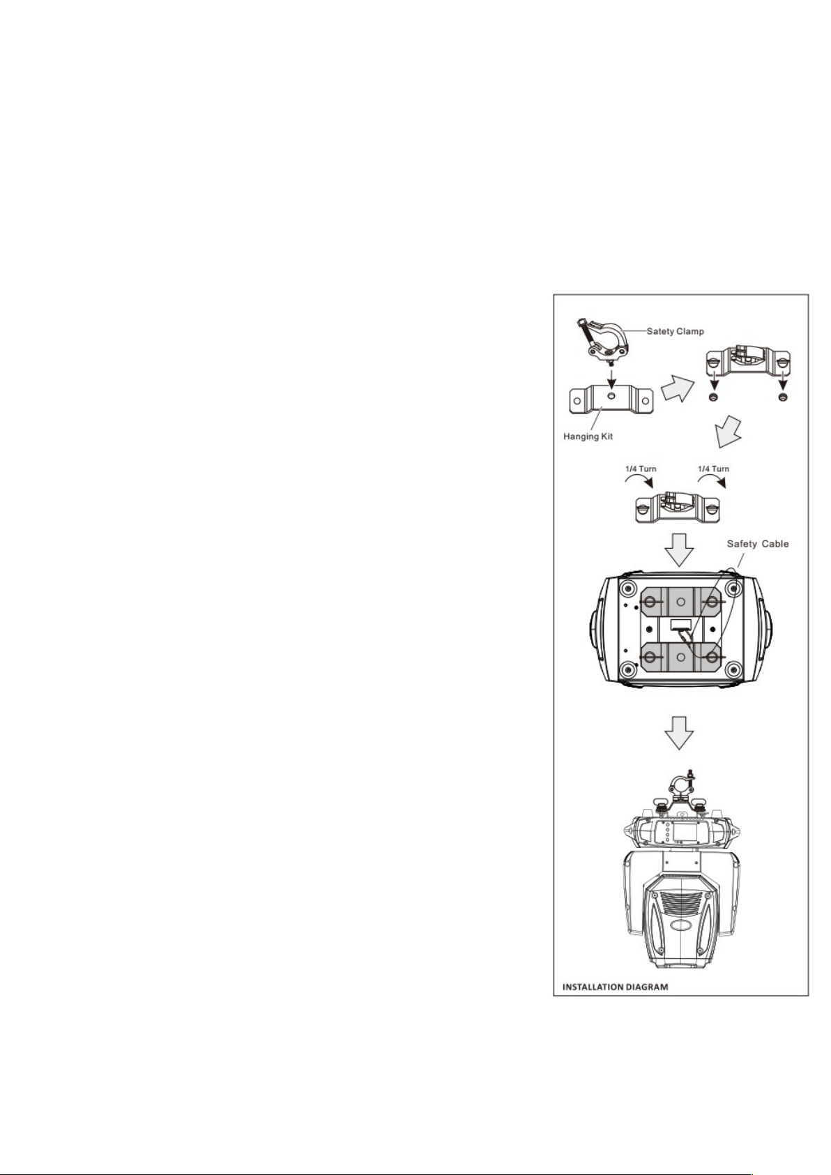
Suspended Installation (Suspension Brackets)
When the Vision 150 Wash is suspended, the suspension brackets need to
be fitted to the baseplate of the unit. These brackets are fitted via quickcouplers, which are inserted into the mounting points and turned by one
quarter to screw them in place. A half-coupler or G-hook can then be
secured via the mounting holes of the brackets. Standard hooks and/or
brackets for 35mm or 50mm poles (truss or lighting stand) are available via
your local retailer.
The hardware required for mounting the Vision 150 Wash to a wall, ceiling
or beam does not come included. If you’re not sure what hardware you’ll
need to install the unit, then contact a specialist for advice. Securing the unit
to a wooden beam will require different hardware than when securing the
unit to a stone wall, for example.
When the Vision 150 Wash is suspended, a safety cable must be used to
secure the unit. A safety cable does not come included but will be available
via your local retailer.
The Vision 150 comes with a safety eyelet which can be screwed into the
base of the unit to secure a safety cable. The safety cable must then be
looped over the truss or stand the unit is suspended from before being
reattached to the hook.
This way, if one or both of the brackets should fail and come loose, the
safety cable will prevent the unit from falling.
A safety cable that’s able to bear at least 10x the weight of the unit must be
used. The safety cable must be installed so that the unit is unable to fall any
further than 30cm. To ensure this, the safety cable can be wrapped around
the truss or stand to shorten the length as needed. The shorter the falldistance allowed by the safety cable, the more the chance of damage or
injury is reduced.
Light Source
The Vision 150 Wash comes fitted with powerful LED light modules coupled
with a special lens that intensifies the effect. Never look into the lens of the
unit from a short distance as the human eye is forced to react too quickly to
the sudden intensity of light. Normally, this will not cause permanent injury,
but will cause blind spots, impairing vision for a short period of time and
causing disorientation and discomfort.
Cooling
The Vision 150 Wash is cooled by fans located in the head and main housing. These will activate
The information included in this user manual is subject to change at any time and without notification:
Version: 1.1 Date & Author Initials: 09-02-2022 RV Revision Date & Author Initials: -
Page 12

automatically as soon as the unit is switched on. Always ensure that the fans and ventilation slots are never
blocked and regularly check that they are functioning properly. Dust and other elements such as synthetic
smoke (precipitated smoke fluid) can affect the functioning and lifespan of the unit.
Temperature-Controlled Fan Systems
This Ayra Vision Series unit is fitted with a built-in temperature-controlled fan system. This system is active
as soon as the unit is switched on and will run at a low speed. As the internal temperature of the unit rises,
the fan speed will increase to enhance the cooling effect.
The fans will rotate at base speed until the internal temperature reaches approximately 30 degrees Celsius,
and will then gradually increase in speed as the temperature rises.
If (for whatever reason) the internal temperature rises to such a level that the fans are unable to sufficiently
cool the unit at their maximum speed, the light output of the LED modules will automatically decrease to
reduce heat production and regain thermal balance, preventing certain components from overheating.
Parts & Repairs
No spare parts are commercially available for this unit, and therefore it cannot be repaired by the user. In
case of any defect, always have the unit inspected and repaired by a qualified technician.
Cleaning & Maintenance
The exterior housing of the unit must be cleaned with a dry or lightly moist microfibre cloth on a monthly
basis. Ensure that the unit is unplugged from the power source before cleaning or performing any
maintenance.
Check that no screws are missing and that all screws are well secured. Tighten any screws where needed.
Check that no corrosion is present on any metal parts of the unit. If any corrosion is present, the unit must be
properly inspected.
Use in Daylight/Direct Sunlight
The Vision 150 Wash is fitted with various optics, including a large central lens. There is a danger of sunlight
beaming inside the unit itself if direct sunlight is able to shine through the optics of the unit. This light can be
concentrated in such a way that the effect is amplified, causing damage to the interior of the unit. In the worst
case, this may cause a fire. Always prevent direct and prolonged sunlight from entering the central lens.
Special DMX Control Features
DMX Terminator & 110 Ohm Impedance
Adding a DMX terminator to the end of your DMX circuit is strongly recommended. This is a termination
resistor that is able to counter reflections in the DMX signal and prevent interference. Always use 110 Ohm
DMX cables to ensure optimal data signal transfer.
While it may work in practice, unexpected reliability and signal stability issues may arise when this unit is
connected using standard XLR microphone cables.
High-quality cabling, a stable power supply and the use of DMX terminators all contribute to a more
consistent, reliable and safe setup.
DMX Terminator
A DMX terminator is commonly placed at the end of the DMX circuit when using this unit in DMX mode. A
DMX terminator places a 120 Ohm resistor between pin 2 and 3 to eliminate any data reflections. Data
reflections can cause any DMX fixtures to behave strangely.
Ready-made DMX terminators can be purchased, but a 120 Ohm resistor can be soldered between pin 2
and 3 of a standard M-XLR plug to complete a terminator.
DMX Splitter/Booster
When more than 32 fixtures are chained in one DMX circuit, it is recommended to add a DMX splitter to
divide the circuit into several groups. This prevents the signal from becoming too weak, especially when long
The information included in this user manual is subject to change at any time and without notification:
Version: 1.1 Date & Author Initials: 09-02-2022 RV Revision Date & Author Initials: -
Page 13
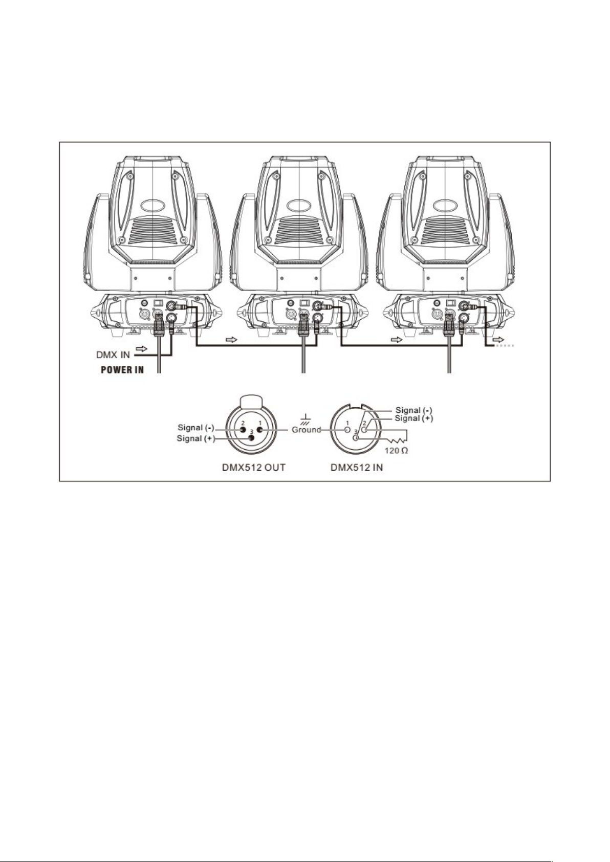
distances need to be bridged between each fixture.
By using a signal distributor and/or booster, the setup is at a far lower risk of signal distribution problems.
This is especially recommended when several fixtures are chained in the same DMX circuit or the DMX
signal needs to travel longer distances between fixture groups.
Illustration of How to Chain Multiple Units
Special Power Output Features
Device Capacity
This device comes with a 3x 1.5mm² thick connecting cable. The internal wiring between the input and output
of this unit is 1.5mm².
This unit comes fitted with a power output that can be linked to the following unit to form a chain. A loopthrough cable that also has 1.5mm² wiring must be used to link the power output to another unit.
The maximum capacity of the power link output is 16 Amperes, minus the power consumption of the unit
itself.
This unit has a maximum power consumption rating of 182 Watts which amounts to almost 1 Ampere. To
ensure safe operation, and to allow for a margin, it is recommended that a maximum of 14 Amperes from the
first unit be passed onto the subsequent units. This means that the total load capacity on the line that
supplies the first appliance with power can never exceed 15 Amperes.
Always take into account the capacity of the power connection used for the first unit in the line (and any other
units in the same line) because, besides your units, other devices may be connected to the same power
group. If this is the case, then the maximum load capacity of the group will be affected, meaning that less
devices (units, equipment etc) can be connected.
The information included in this user manual is subject to change at any time and without notification:
Version: 1.1 Date & Author Initials: 09-02-2022 RV Revision Date & Author Initials: -
Page 14

In practice, this means that a maximum of 14 of the same units can be connected via the power link output.
This is normally more than sufficient for a chain like this, as long as the power group is not being used by
other electronic devices.
Ideally, other devices (such as heavy strobe lights, smoke machines and so on) that consume more energy
than this unit are connected to their own power supply.
The built-in fuse of this unit only protects and fuses the unit itself. If the fuse blows as the result of an
electrical fault, the rest of the chain will continue to function normally.
If there is a problem with the unit that affects the entire chain, such as a short-circuit, then normally the mains
fuse (usually found in the circuit breaker of the distribution box) of the power group will cut power to all
devices connected to that group.
Bear in mind that, if your setup is connected to a third-party system, such as those in an events space, then
the power group can only be restored via the meter box.
The installations at these kinds of venues are not usually accessible by third parties.
Always check with the venue, or contact the relevant organiser, regarding accessibility in the event of poweroutages such as short circuits.
The information included in this user manual is subject to change at any time and without notification:
Version: 1.1 Date & Author Initials: 09-02-2022 RV Revision Date & Author Initials: -
Page 15

DMX-Lighting Problem Shooting
If you happen to encounter any problems while using this unit, we recommend checking this troubleshooting
section to see if a solution can be found. If none of the suggested solutions included below solve your
particular problem, please contact your local retailer for further advice.
This troubleshooting section includes all of the most common possible issues and is not a complete list of
every possible fault, defect, and their subsequent solution. This section is generally focussed on solving
problems regarding DMX lighting. Some of the included problems, causes, and solutions may not apply to
your situation since product specifications can differ.
Problem Possible Cause Solution
The unit is not switching on Blown fuse Check that the fuse is not blown.
If it is, replace it with a new fuse
of the same rating and type.
Power cable not plugged in Make sure that the power cable is
securely plugged into the rear of
the device and into a mains
power socket.
The unit is not responding to
DMX signals
Incorrect DMX start address Make sure that the correct DMX
start address is set
DMX controller set to ‘blackout’ Make sure that the ‘blackout’
function of the DMX controller is
switched off.
The polarity switch of the DMX
controller is not correctly set
Try flipping the DMX controller
polarity switch.
Unit not responding. No DMX
signal indication
Test the connected cables and
replace them if needed.
The unit is not responding to
sound/music
Incorrect operating mode Check that the correct (sound
controlled) operating mode is
activated.
Microphone sensitivity level set
too low
Check the microphone sensitivity
level and increase the value if
necessary.
Speaker is too far away, or not
enough lower frequencies (bass)
Place the unit closer to the
speaker (or vice versa) and/or
enhance lower frequency
reproduction of the sound
system. The built-in microphone
is not triggered by higher
frequencies
The light projection is
minimal/weak
Dirty or dusty optics Clean the lens and/or other optics
of the unit
Dimmer is not fully open Check that the dimmers of the
spots and/or the master dimmers
are fully open.
The DMX signal is intermittent
and some units are blinking or
acting strangely
Broken/defective cables Test all connected DMX cables
and replace any broken or
defective cables if necessary.
Power interference on DMX
signal
Avoid installing power cables
parallel to DMX signal cables.
No DMX terminator End the DMX circuit with a DMX
terminator.
Signal loss or DMX circuit
malfunction
End the DMX circuit with a DMX
terminator or connect a booster
The information included in this user manual is subject to change at any time and without notification:
Version: 1.1 Date & Author Initials: 09-02-2022 RV Revision Date & Author Initials: -
Page 16

after every 32 fixtures in the
circuit.
The unit is performing jerking
movements
Movement is programmed at too
slow a speed
When the moving head is set at a
very slow speed, movements are
performed step by step. In DMX
mode this can be corrected
slightly by lightly adjusting the
pan/tilt speed per unit
Pan or Tilt range is minimal The pan and tilt range needs to
be reset
Check that the pan and tilt range
is correctly set on your lighting
desk or DMX controller and
correct it as needed.
Pan and/or Tilt range are
responding the wrong way
around
Pan or tilt invert is set Check that the pan or tilt invert is
not set and switch it on or off as
needed.
Projected light bundle is not
sharp
Optical elements need adjusting This unit features various
elements for optimising or
adjusting the optics. Depending
on the settings and the space, a
shape or beam may not be
projected sharply. Via the
motorised focus and other optic
parameters, the bundle can be
sharpened.
Display is mirrored vertically at
180 degrees
Display is inverted so it can be
read when unit is suspended
The display can be inverted
(flipped upside down) so that it
can still be read when the unit is
suspended. This function is
described earlier in this manual.
The information included in this user manual is subject to change at any time and without notification:
Version: 1.1 Date & Author Initials: 09-02-2022 RV Revision Date & Author Initials: -
Page 17

Technical Specifications
Specifications:
- Versatile professional LED moving head
- Wash edition: intended for the even illumination of large surfaces and produce thousands of atmospheric
colour combinations via a powerful RGBW COB LED
- Light source: 150W COB RGBW LED light source (red, green, blue, white)
- LED light source lifespan: 50,000 hours
- Various operating modes (automatic, sound controlled, DMX, master/slave)
- 14 /12 DMX channels
- Offset calibration for all step motors
Optical Characteristics & Beam
- Broad wash beam with soft edges (26 degrees nominal)
- 0-100% linear dimmer
- Optional halogen simulation (die-off effect), via DMX
- Built-in LED shutter effect, with strobe function up to max. 25 flashes per second
- Built-in shutter-effects, including pulse and random strobe
Pan/Tilt
- Pan-range: 360 / 540 / 630 degrees (540 degrees default)
- Tilt-range: 90 / 180 / 270 degrees (270 degrees default)
- Automatic pan/tilt correction
- Pan and tilt fine option via DMX
- Pan and tilt movement speed adjustment via DMX
- Magnetic zero-point positioning
- Pan and tilt inversion option
Dimmer/Strobe
- 0-100% dimmer
- Individual dimmer for each basic colour for limitless colour combinations (independent 0-100% dimmer for
red, green, blue and white)
- Various shutter and strobe effects (o.a. random strobe)
Physical Features
- 3-pin XLR DMX inputs and outputs
- Locking power port with Power Link function so other units can be chained and powered
- Colour display (2.4” TFT) with 4 menu buttons for function control
- Durable housing with plastic caps
- Handles fitted to sides of base
- Base fitted with quick-coupler bracket mounts
- Base fitted with metal eyelet for securing a safety cable during suspended installation
- Can be set up in a standing or suspended position
- Connection voltage: 100 - 240V AC, 50/60 Hz
- Max. power consumption: 182 Watt
- Fuse: T4A 250V
- IP20 protection class
- Environmental temperature restrictions: min.-35 degrees Celsius, max. 45 degrees Celsius
- Unit dimensions: 260 x 150 x 348mm
- Packaging dimensions: 370 x 275 x 415mm
- Unit net weight 5.62 kg
- Weight plus packaging: 7.12 kg
The information included in this user manual is subject to change at any time and without notification:
Version: 1.1 Date & Author Initials: 09-02-2022 RV Revision Date & Author Initials: -
Page 18
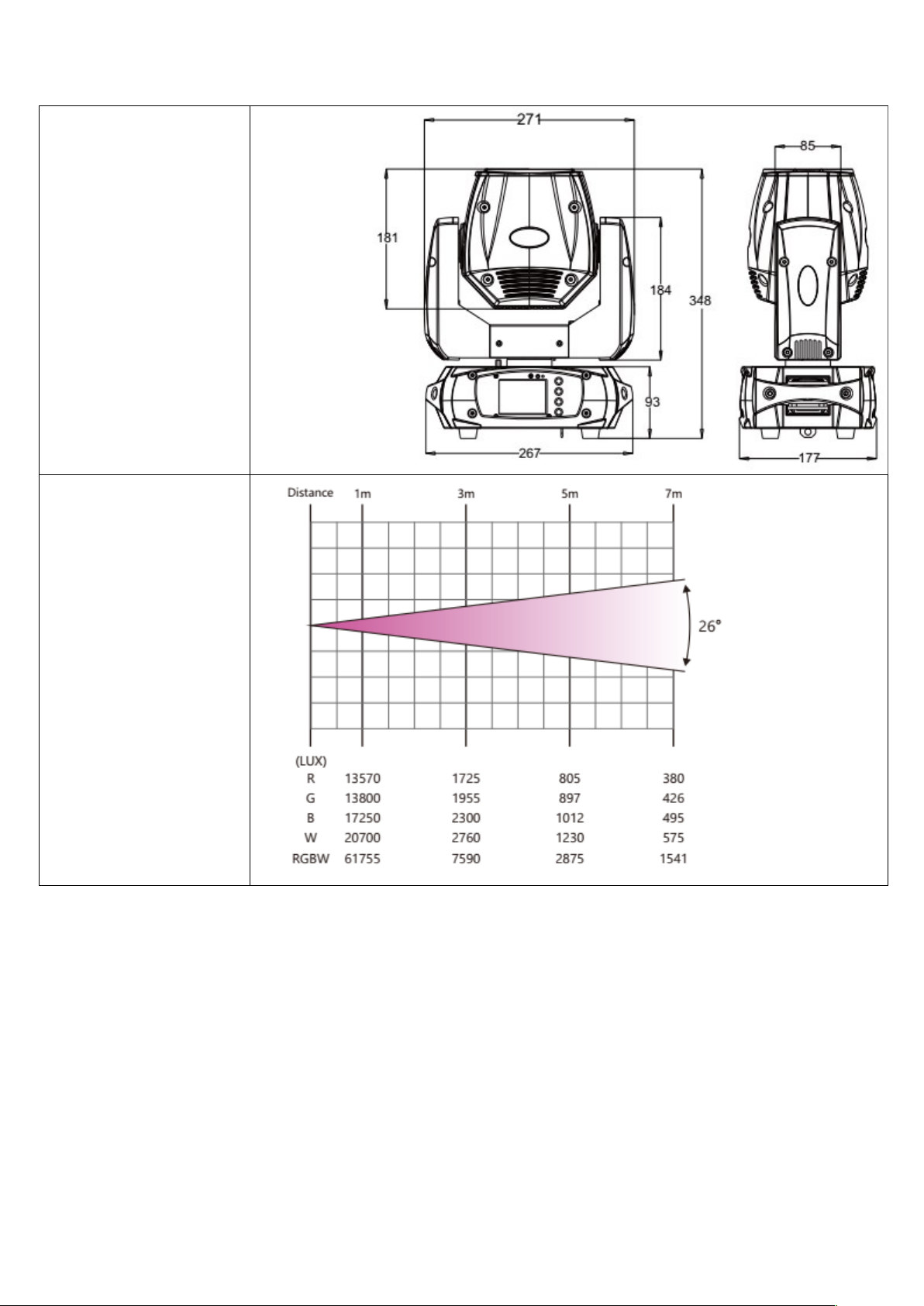
Illustrations of Unit Features
Dimensions (mm)
Photometric features of unit
The information included in this user manual is subject to change at any time and without notification:
Version: 1.1 Date & Author Initials: 09-02-2022 RV Revision Date & Author Initials: -
 Loading...