

Page 1
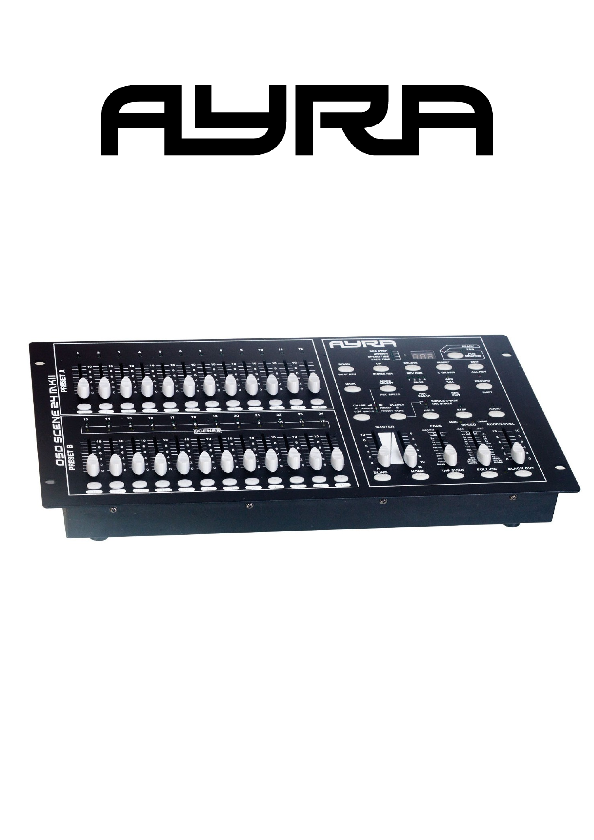
OSO SCENE 24
DMX controller
User manual
Any information and illustrations shown in this user manual are subject to change without further notice.
User manual version: 2.0 Creation date + author initials: 29-03-2014 RV Revision date + author initials: 29-03-2014 RV
Page 2
Safety instructions
This unit must be operated by, or under the supervision of an adult. This device is not suitable for children.
Every person involved with the installation, operation and maintenance of this device has to:
- Be qualified
- Follow the instructions of this manual
- Make sure there is no damage caused by transport. If the device seems damaged from the outside, do not
use it and contact your dealer for more information and consultation.
- To make sure the device maintains in perfect condition and for safe operation, it is necessary for the user to
follow the instructions and warning notes of this user manual.
- Damage caused by improper use or modifications to the device are not covered by warranty.
- This device does not have any user-serviceable parts inside. Servicing of this device needs to be done by
qualified technicians.
Important notes regarding safety and health:
- Never let the power cord come in contact with other cables. Handle the power cord and all connectors with
the mains with caution.
- Never remove any warning or informative labels from the unit
- The ground contact always needs to be connected. Do not cover or remove the ground contact.
- Never leave cables lying around
- Do not open the device and do not modify any hard- or software of this unit.
- Do not insert this object into air vents.
- Do not connect this device to a dimmerpack.
- Do not switch the system on and off frequently as this will reduce the lifespan of the device.
- Do not drive the inputs of the fixture with a signal larger than required to work at full performance.
- Only use this device indoor, avoid contact with water, moist or other liquids. Do not place items filled with
liquids on top of the unit.
Any information and illustrations shown in this user manual are subject to change without further notice.
User manual version: 2.0 Creation date + author initials: 29-03-2014 RV Revision date + author initials: 29-03-2014 RV
WARNING!
Always keep this device away from moisture and rain! Hazardous electrical shocks may occur!
WARNING!
Only connect this device to a matching power outlet. This device is intended to work on a
specified AC currency. Connecting this device to power outlets with other voltages may result in
permanent damage and possible hazardous situations, such as fire or electrical shocks!
WARNING!
Be careful with every operation of this device. Touching live wires inside and outside the unit
may cause hazardous electrical shocks!
Page 3

- Avoid nearby flames or heat sources, do not place this device near flammable liquids, gas or flammable
items.
- Always disconnect the device when it is not in use for a longer period or time, when servicing is needed or
when the device needs cleaning.
- Only handle the power cord by its connectors. Never pull the cable to remove a connector from its socket,
as this could lead to damage and electrical shocks.
- Always operate this device with a stable AC current.
- Always operate this device with the AC ground wire connected to the electrical system's ground.
- Never use other types of cables than specified in the manual, do not use defective or bad functioning
cables. Contact your dealer when the included or required cables do not work properly with this device.
- When the device has been exposed to large temperature differences (for example, transport from outdoor
to indoor), do not connect the device immediately. Do not activate the unit until it has reached room
temperature, as moist might build up inside the unit, which may cause shortcuts and/or electrical shocks.
Guidelines and types of use:
- This device is intended to be used by professionals on stage, in theaters, clubs and other equal venues.
- This device is not suitable for children and always needs to be operated by an adult.
- Only use the device when the environment is suitable and will not cause any damage. Do not use the
product in moist or dusty environments, or where long-term damage may occur such as:
- indoor swimming pools where chlorine is used.
- Beaches, where sand and salt are present.
- Outdoor, without roof protection
- Indoor areas where intense heat sources are present or where the temperature exceeds levels
which are comfortable for humans.
- Only use the included power adapter and only connect the device to a suitable power outlet with the correct
output voltage. Connecting the device to a power outlet with the wrong type of voltage or using the product
with a wrong type of power supply may cause permanent damage to the device.
- Avoid shocks and collision during use and transport. Do not transport the device while in use. Avoid brute
force during the installation and operation of this device.
- Familiarize yourself with the functions of the device before use. Do not allow operation of the device by
unskilled or unqualified people.
- Use of the device in other ways than described in this user manual may cause damage and injury. Ayra
does not take responsibility for any damage or injury caused by improper use.
Storage and transport:
- This device is intended for mobile use. When transported, use the original packaging of the product, or a
fitting flightcase, preferably filled with foam.
- This device is not intended for permanent use. Operation breaks will ensure that the lifespan of the device
remains unchanged.
- If the device is not used for a longer period of time, disconnect it from its power source and store it in its
original packaging, or in a fitting flightcase.
- Store the device indoor, dry and do not expose the device to extreme temperature differences.
Housing:
- Inspect the housing of the device frequently. Severe dents, cracks and missing screws should be avoided
at all costs. Do not use the device when the housing is not in optimal condition. Contact your dealer or a
skilled technician when in doubt about the state of the device
- Check the fixture and screws for corrosion. Corrosion should not be present on the fixture. Contact your
dealer or a skilled technician when corrosion is found on the fixture
- Every power or signal chassis/connector should be mounted tightly. Do not use the device when connectors
are loose.
- Do not use the power cord when the cores are visible. Contact your dealer for a replacement if needed.
- Avoid the buildup of dust and dirt. Clean the exterior of the fixture every month with a dry or damp cloth.
When using the device intensively, the cleaning frequency needs to be increased.
Fuses:
- The main fuse of this device is to be found on the rear of the device. In most cases, directly next to the
power inlet.
- Only replace a fuse for a new one with the same type and rating! Do not use a fuse with a higher or lower
Any information and illustrations shown in this user manual are subject to change without further notice.
User manual version: 2.0 Creation date + author initials: 29-03-2014 RV Revision date + author initials: 29-03-2014 RV
Page 4

rating.
- Do not bridge the fuse with electrical wires, aluminum foil, as the fuse is used for protection against
electrical shocks and short circuit.
- Always mount the fuse cover back to the fuse compartment.
Any information and illustrations shown in this user manual are subject to change without further notice.
User manual version: 2.0 Creation date + author initials: 29-03-2014 RV Revision date + author initials: 29-03-2014 RV
Page 5

Box contents
Box contents
1x OSO Scene 24 DMX controller
1x power supply
Unit and accessory inspection
- Always check the unit, box and accessories for possible damage before use. If you suspect that something
is wrong with the unit, do not connect it to a power source! When you suspect that your unit is broken or
damaged, contact your local dealer or a certified technician to inspect the unit.
- If any of the parts that should be included is missing, contact your local dealer for help.
- If the box appears severely damaged, soaked with liquid or ripped apart, do not unpack the product and
contact your local dealer for help and more information.
- Always preserve the original box and packaging materials as long as the warranty period is active. This
way, the device can be transported for repair and inspection safely.
Any information and illustrations shown in this user manual are subject to change without further notice.
User manual version: 2.0 Creation date + author initials: 29-03-2014 RV Revision date + author initials: 29-03-2014 RV
Page 6
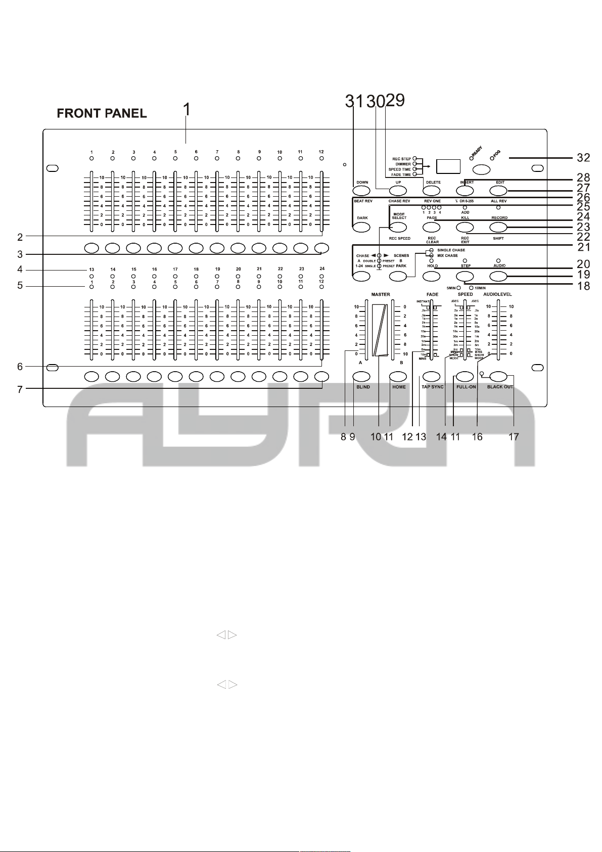
Device overview
1. PRESET A LEDS.
2. CHANNEL SLIDERS 1-12: these sliders will adjust the output of 1 to 12 channels from 0 to 100
% or 0 to 255.
3. Flash key 1-12: press to activate maximum channel output.
4. PRESET B LEDS.
5. SCENE LEDS.
6. CHANNEL SLIDERS 13-14: these sliders will adjust the output of 13 to 24 channels from 0 to
100% or 0 to 255.
7. Flash key 13-24: press to activate maximum channel output.
8. MASTER A SLIDER: the slider will adjust the total output of preset A.
9. BLIND KEY: in CHASE SCENES, this key, when activated, enables a function to only use
the sliders and flash-buttons for the output of each channel.
10. MASTER B SLIDER: the slider will adjust the total output of preset B.
11. HOME KEY: in CHASE SCENES, this key, when activated, enables a function to only
change the values of channels by using pre-defined programs
12. FADE TIME SLIDER: move to adjust fade time.
13. TAP SYNC: in AUTO CHASE, press it twice to define the chasing speed (for example, to the
Any information and illustrations shown in this user manual are subject to change without further notice.
User manual version: 2.0 Creation date + author initials: 29-03-2014 RV Revision date + author initials: 29-03-2014 RV
Page 7
beat of the music)
14. SPEED SLIDER: move to adjust chasing speed.
15. FULL ON KEY: when activated, all channel outputs will be maximum and disable BLACK OUT.
16. AUDIO LEVEL SLIDER: move to adjust the audio-sensitivity for the music-controlled mode.
17. BLACK OUT KEY: this function forces all DMX-output to “0”, while the other parts of the
controller are still active.
18. STEP KEY: press it once and the program will change one step at a time.
19. AUDIO KEY: press to get into audio control.
20. HOLD KEY: press and hold, to pause the output.
21. PARK: IN CHASE SCENES mode, press it to select SINGLE CHASE OR MIX CHASE. In
DOUBLE PRESET, pressing PARK B is same as MASTER B at the maximum. In SINGLE
PRESET, pressing PACK A is same as MASTER A at the maximum.
22. REC EXIT: exit record. When the LED is active, it is in KILL mode. Press a random FLASH
button and all output is reduced to zero except the one channel you selected.
23. RECORD KEY: press it to record program steps or create chases..
24. PAGE KEY: press it to select the desired SCENE program on the appropriate page.
25. MODE SELECT: by pressing the key you can select CHASE SCENES DOUBLE RESET or
SINGLE PRESET.
26. DARK KEY: press it to pause the whole output and reducing all output to 0, including FULL ON
and FLASH.
27. ALL REV: the key, when activated will reverse chasing direction of all program.
28. 0% - 100% OR 0-255 KEY: press to select 0% - 100% or 0-255 on DISPLAY.
29. REV ONE: press and hold the key, then press any one of PRESET B .the SCENE program will
chase in reversed direction.
30. CHASE REV: this key inverts the chase direction of a chase, with use of the SPEED slider.
31. BEAT REV: this key inverts the chase direction of a chase, with use of the built-in music
controlled mode
32. FOG MACHINE: activate a connected fog machine. (working with all types and brands not
guaranteed)
Any information and illustrations shown in this user manual are subject to change without further notice.
User manual version: 2.0 Creation date + author initials: 29-03-2014 RV Revision date + author initials: 29-03-2014 RV
Page 8
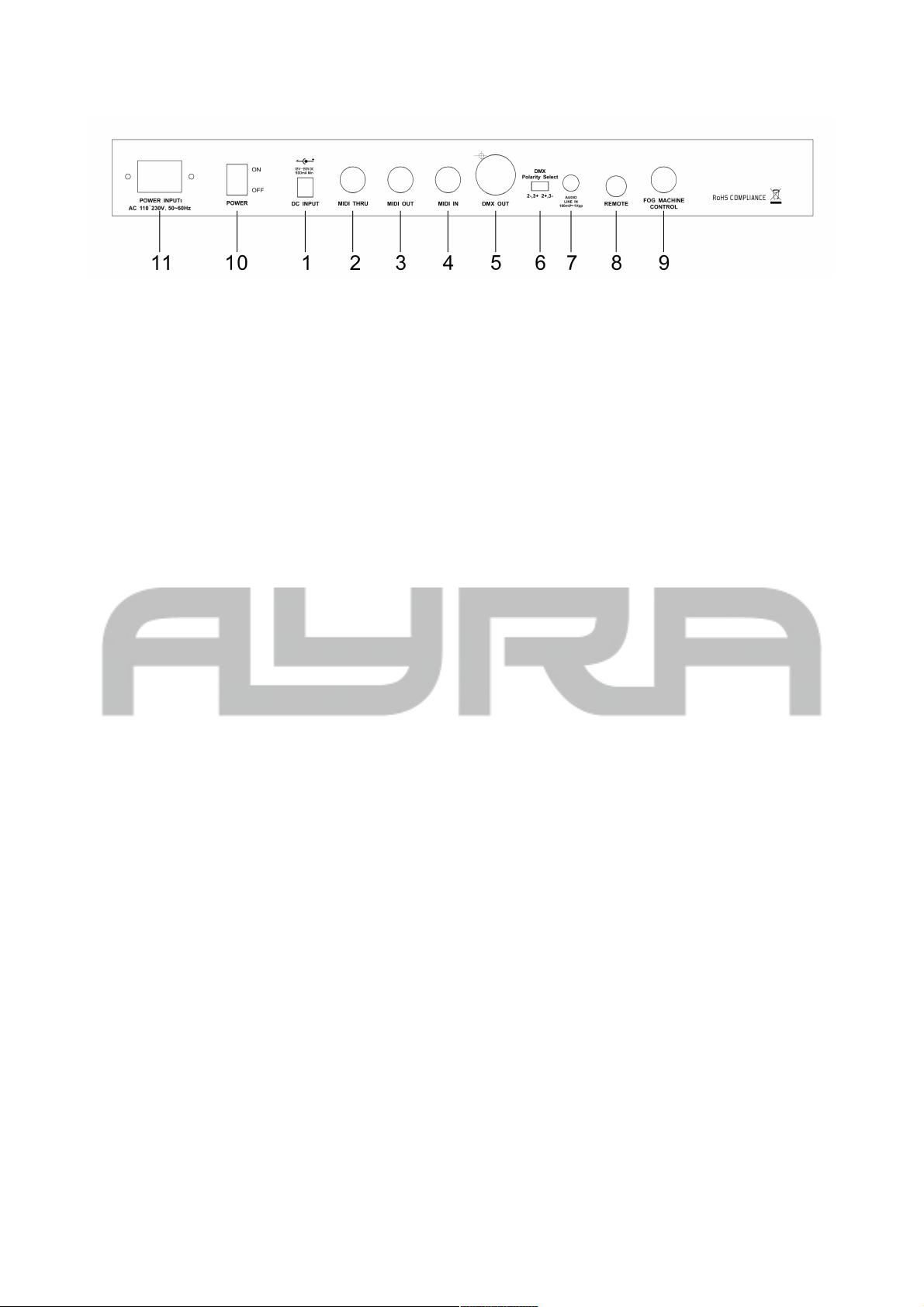
REAR PANEL
1. POWER INPUT : DC 12V-18V, 500mA MIN.
2. MIDI THRU: use to transmit MIDI data received on the MIDI IN connector.
3. MIDI OUT: transmit MIDI data originated by itself.
4. MIDI IN: received MIDI data.
5. DMX OUT : DMX output.
6. DMX POLARITY SELECT: select the polarity of DMX output. (pin 2 and 3 inversion, Martin
Protocol)
7. AUDIO INPUT: line input for direct mixer output. 100mV-1Vpp.
8. REMOTE CONTROL: FULL ON and BLACK OUT are remote controlled using 6.35mm
stereo jack and and a footpedal (not included!).
9. FOG MACHINE: connect a fog machine with a 5-pin DIN connector (working with every type
and brand not guaranteed).
10. Power switch
Any information and illustrations shown in this user manual are subject to change without further notice.
User manual version: 2.0 Creation date + author initials: 29-03-2014 RV Revision date + author initials: 29-03-2014 RV
Page 9

General use
1. RECORD ENABLE
1) Press and hold RECORD KEY.
2) Press FLASH 1, FLASH 6, FLASH 6, FLASH 8 keys in sequence.
3) Release RECORD, the led is lighting, recording is ready.
2. ERASE ALL PROGRAMS
1) Press and hold RECORD KEY.
2) Press FLASH 1, FLASH 4, FLASH 2, FLASH 3 IN SEQUENCE.
3) Release RECORD.
3. CLEAR MEMORY
1) Press RECORD key, and then press REC CLEAR KEY.
2) Release RECORD and REC CLEAR at a time.
4. RECORD PROGRAM
1) Set desired channel and record it.
2) Light the relevant page LED.
3) Press, RECORD then press appropriate FLASH button.
4) Release RECORD.
For example: create a program, record it in the 28th SCENE.
1) Clear memory.
2) Light 1-24 SINGLE LED.
3) Set channel slider 1-24 to min. position and MASTER A to max. position.
4) Move slider 1 to max. position, press RECORD then move it to minimum position. Continue moving
other sliders until all sliders are set.
5) Press PAGE key to light page 3 LED.
6) Press RECORD, then press FLASH 16.
7) Release RECORD and FLASH 16, the program of 1-24 full on in sequence is recorded in the 28th
SCENE.
5. DELETE A PROGRAM
1) Press PAGE to light the desired PAGE LED.
2) Press RECORD, the press appropriate FLASH twice.
For example: to delete the 40th SCENE PROGRAM.
1) Press PAGE to light page 4 led.
2) Press RECORD, then press FLASH 16 twice.
3) Release RECORD.
6. SCENE EDIT ENABLE
Any information and illustrations shown in this user manual are subject to change without further notice.
User manual version: 2.0 Creation date + author initials: 29-03-2014 RV Revision date + author initials: 29-03-2014 RV
Page 10

1) Press PAGE to select the correct page, the corresponding PAGE LED will light up.
2) Press MODE SELECT to activate the CHASESCENES LED.
3) Press EDIT and desired scene FLASH.
4) Release EDIT and the FLASH, the relevant SCENE LED is lit and others go out, now editing is
enable.
For example: to make the 11th SCENE program enter EDIT mode.
1) Press PAGE to light PAGE 1 LED.
2) Press MODE SELECT to light CHASESCENES LED.
3) Press EDIT and FLASH 23.
4) Release EDIT and FLASH 23.
7. EXIT EDIT MODE
1) Press RECORD, then press EXIT.
2) Release RECORD and EXIT.
8. DELETE STEP
1) in EDIT mode, press STEP to play the program until you reach the step you want to delete..
2) Press DELETE. The step is deleted and the next step will show.
9. ADD STEP
1) IN EDIT mode. Record the step to be inserted.
2) Press STEP to execute the program till the step you want to insert before the selected step.
10. MODIFY STEP
1) In EDIT mode. Press STEP to play the program until you reach the step you want to modify.
2) Press UP or DOWN and desired FLASH, the output will show on display, adjust the value according
to your wish and release FLASH
11. Change showing mode of dimmer
PRESS and hold RECORD, then press 0% or 0-255 KEY
12. SELECT AND RUN PROGRAM
1) Press MODE SELECT TO light CHASESCENES LED.
2) Press PAGE to light the desired page LED.
3) Mode MASTER B slider to max. position.
4) Move desired scene channel slider to min; then move it up, the program is selected and executed.
13. RUN A PROGRAM WITH REGULAR BEAT
Any information and illustrations shown in this user manual are subject to change without further notice.
User manual version: 2.0 Creation date + author initials: 29-03-2014 RV Revision date + author initials: 29-03-2014 RV
Page 11

1) Press AUDIO to extinguish AUDIO LED.
2) Press PARK to light MIX MODE LED.
3) Select to run the scene program.
4) Move the SPEED slider or press TAP SYNC twice to define beat time.
5) Press REC SPEED and the desired FLASH KEY. then the program will be executed with the beat
time.
14. RUN A PROGRAM WITH SPEED SLIDER.
1) Press AUDIO to extinguish AUDIO led.
2) Press PARK to light MIX MODE led.
3) Select to run the scene program.
4) Move SPEED slider to SHOW MODE position.
5) Press REC SPEED, then press the appropriate FLASH.
For example: run the 14th SCENE program with the speed of 1 step per second, then set it to be
controlled by speed slider.
1) Press MODE SELECT to light CHASESCENES LED.
2) Press AUDIO to extinguish its LED.
3) Press PARK to light MIX MODE LED.
4) Move all channel sliders to the minimal position.
5) Move MASTER B slider to the maximum position.
6) Press PAGE to light PAGE 2 LED.
7) Move the 14th channel slider to maximum position.
8) Move SPEED slider until 1.00 appears in the display and SPEED LED is lit.
9) Press REC SPEED and FLASH 14, then release both keys; the 14th SCENE program is set to run 1
step per second.
10) Move SPEED slider to SHOW MODE position. Press REC SPEED and the 14th FLASH, then the
14th SCENE program is set to be controlled by SPEED slider, move SPEED slider until 0.10 appears
on the display, the 14th program will run with 10 steps per second.
15. SPEED SETTING
A: SLOWEST SPEED SLIDER SETTING (5 MIN)
1) Press and hold RECORD.
2) Press the 5th FLASH KEY 3 times, then release RECORD.
3) THE 5MIN LED is lit, which means that 5MIN SPEED slider is done.
B: SLOWEST SPEED SLIDER SETTING (10MIN)
1) Press and hold RECORD.
2) Press the 10th FLASH KEY 3times, then release RECORD.
3) The 10 MIN LED is lit, which means that 10MIN SPEED slider is done.
16. MIDI IN SETTING
Any information and illustrations shown in this user manual are subject to change without further notice.
User manual version: 2.0 Creation date + author initials: 29-03-2014 RV Revision date + author initials: 29-03-2014 RV
Page 12

1) Press and hold RECORD
2) Press 1st FLASH KEY 3times, then release RECORD, when CHI appears on the display, you can
select MIDI IN channel from 1st FLASH to 16th FLASH.
3) After you press desired FLASH, the appropriate channel LED is lit.
4) Press RECORD and EXIT to withdraw MIDI IN setting.
17. MIDI OUT SETTING
1) Press and hold RECORD
2) Press 2nd FLASH KEY 3 times, then release RECORD, when CHO appears on display, you can
select MIDI IN A channel from 1st FLASH TO 16th FLASH.
3) After you press desired FLASH, the appropriate channel led is lit.
4) Press RECORD and EXIT to quit the MIDI OUT setting.
18. RECEIVE FILE DUMP
1) Press and hold RECORD.
2) Press 3rd FLASH KEY 3times, then release RECORD, when IN appears on display, it is ready to
receive file dump.
3) All other operations are void when receiving file dump. It will withdraw receiving file dump
automatically when receiving is over or mistakes is occurred. Power on after power off also pauses
receiving file dump.
19. SEND FILE DUMP
1) Press and hold RECORD.
2) Press 4th FLASH KEY 3times, then release RECORD, when OUT appears on display, it is ready to
receive file dump.
3) All other operations are void when receiving file dump. It will withdraw sending file dump
automatically when sending is over or mistakes is occurred. Power on after power off also pauses
receiving file dump.
20. DETAILED DESCRIPTION
1) FADE TIME: The time it takes for a channel to go from one value to another value (fast or smooth)
2) SINGLE MODE: SCENE program is executed one by one and the No. is showing on display. Its
speed is controlled by SPEED slider.
3) MIX MODE: ALL selected program are executed synchronously, each is allowed to have respective
chasing speed.
4) When CHASESCENES LED is lit, you can select the scene programs using the PRESET B channel
sliders. BLIND one of PRESET B channels ,the appropriate channel slider together with MASTER A
slider control its output, and the maximum dimmer of the program is maintained until you HOME the
channel.
5) FADE TIME & SPEED TIME INDICATIONS
A: when time is more than 1minute, the indication includes two dots.
For example: 1minute and 15 seconds is shown as 1.15.
4 minutes and 30 seconds is shown as 4.30
Any information and illustrations shown in this user manual are subject to change without further notice.
User manual version: 2.0 Creation date + author initials: 29-03-2014 RV Revision date + author initials: 29-03-2014 RV
Page 13
10 minutes is shown as 10.0
B: when time is less than 1 minute, the indication includes one dot only.
For example: 11.5 second is shown as 11.5
1.2seconds is shown as 1.2
0.55 seconds is shown as 0.5
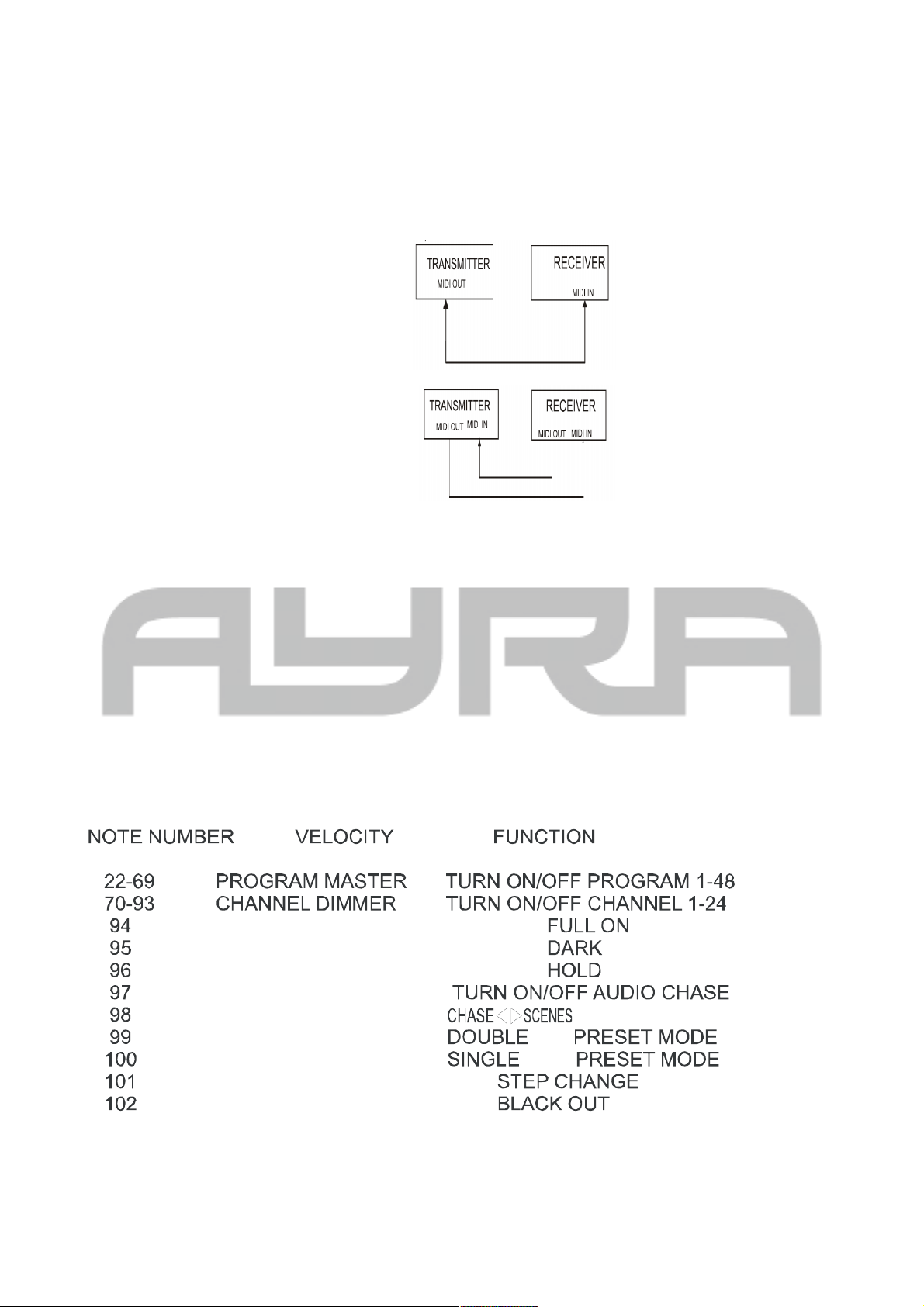
6) Transmit and receive file
A: open loop mode:
B: closed loop mode:
NOTE: when sending file dump in open loop mode, you should set up the receiving mode for the receiver,
otherwise receiving is disabled.
7) When the power voltage is too low, the display shows LOP. Check whether the power is OK. It is normal
that LOP appears for a short while just after the power is turned on.
21. MIDI RUN
1) If MIDI data is not received within 10minutes, the channel and program turned on by MIDI will be cleared.
2) When sending or receiving file dump, the device ID is 55H. All information (including system data) is sent
or received in file dump. You can send SCENE programs to store on another unit, you can also receive
SCENE programs from storage or another unit.
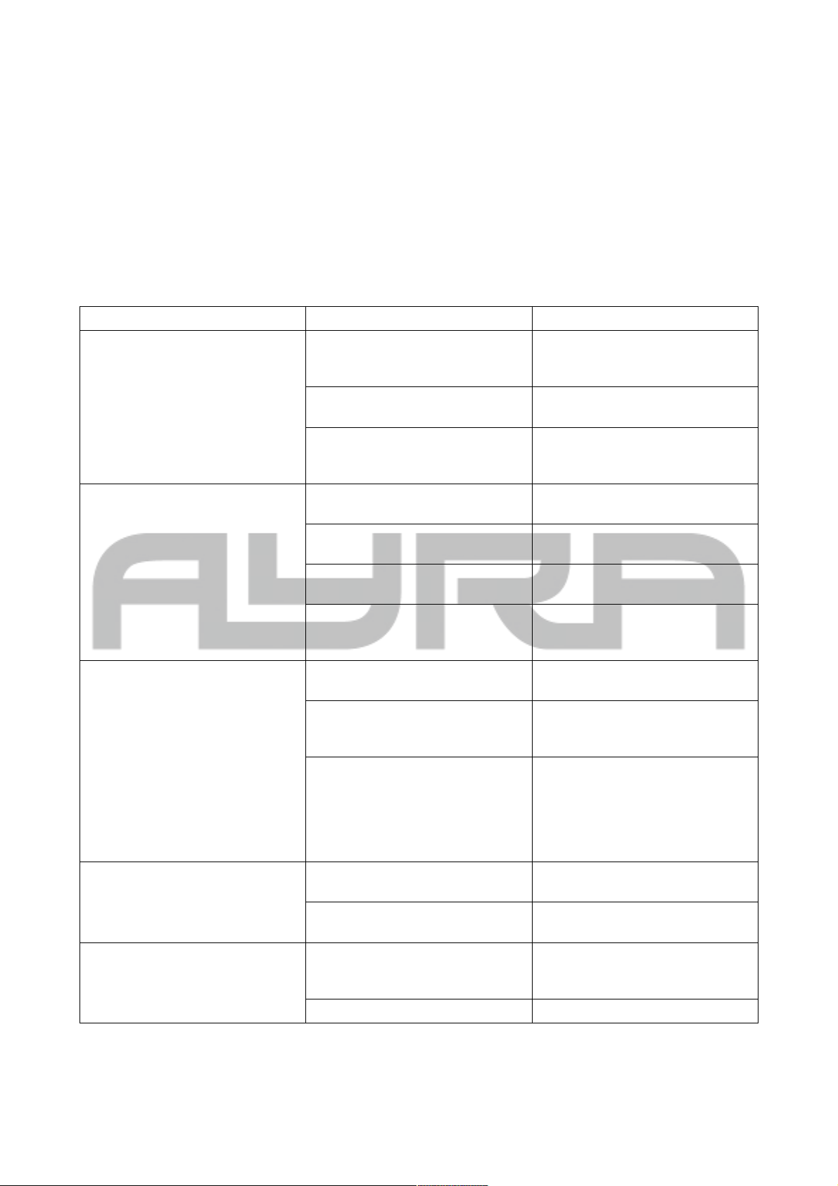
3) This unit sends or receives NOTE information. Relevant functions are as followed:
Any information and illustrations shown in this user manual are subject to change without further notice.
User manual version: 2.0 Creation date + author initials: 29-03-2014 RV Revision date + author initials: 29-03-2014 RV
Page 14
DMX lighting troubleshooting
If you have any problems with DMX lighting, consult this troubleshooting section to solve any difficulties with
your product. If this troubleshooting section does not solve your problem, contact your dealer for more
information and help.
This troubleshooting section contains the most frequent problems and is not a complete collection of possible
faults, defects and solutions. The troubleshooting section applies for DMX controllers, DMX cabling and DMX
lighting fixtures. It is possible that not all described problems, causes and solutions apply to your situation as
product details may vary from product to product.
Problem Possible Cause Solution
The fixture does not activate itself Blown fuse Check the fuse compartiment for
blown fuses and replace it if
necessary.
No power cable plugged in Plug in the power supply to a
matching power outlet
Power switch is not in the ON
position
Turn on the device by switching
the ON/OFF switch to the ON
position, if available
The fixture does not respond to
DMX signals
Wrong DMX address Set the DMX address to the right
value
DMX controller blackout function
activated
Deactivate the blackout function of
your DMX controller
Faulty positioning of the DMX
polarity switch on the controller
flip the polarity switch on your
DMX controller
No response or DMX activity
signal LEDs active
Check your DMX cables for
possible connection breaks and
replace them if necessary.
The fixture does not respond to
sound
Wrong working mode selected. Check if the sound activated mode
of the fixture is activated.
Microphone sensitivity level is set
too low
Increase the microphone
sensitivity of the built-in
microphone
Speaker placed too far away or
lack of bass
Place your lighting effect closer to
your speakers (or vice versa)
and/or increase low frequency
volumes. The microphone will not
be triggered with high pitched
sounds.
The beam output is very low Dirty/dusty optics Clean the lens and/or other optics
with a dry or damp cloth
Dimmer is not set to full output Set all dimmer levels to 100% on
your DMX console
Sometimes the DMX signal is lost
and/or some fixtures are
flickering / behaving odd
sometimes
Faulty/broken DMX cables Check your DMX cables for
possible connection breaks and
replace them if necessary.
Power cable interference on your Avoid installing the DMX and
Any information and illustrations shown in this user manual are subject to change without further notice.
User manual version: 2.0 Creation date + author initials: 29-03-2014 RV Revision date + author initials: 29-03-2014 RV
Page 15
DMX signal (high) power cables parallel to
each other.
No DMX terminator Apply a DMX terminator at the end
of your DMX-chain
Signal loss or distortion in DMX
values
Apply a DMX booster in your DMX
chain after 32 fixtures or less. After
a maximum of 32 fixtures the DMX
signal needs to be refreshed.
Moving parts are not functioning
well, values do not match and/or
rattling sounds are noticed
Faulty stepping motor positioning Possible value loss of stepping
motors. Activate the reset function,
or unplug the power supply and
plug it back in to activate the reset
program. This will reset all values
to the original 0-point.
The fixture does not respond fast
enough to the set speed on my
DMX controller
Moving parts can not keep up with
the set speed
Decrease the chase speed of your
DMX controller, as the stepping
motors of your fixture need some
time to move from one point to
another.
The fixture does not respond to all
DMX-channels
Wrong DMX channel mode Check the DMX channel mode of
the fixture. If the wrong value is
set, change the channel mode to a
different setting and try again.
Any information and illustrations shown in this user manual are subject to change without further notice.
User manual version: 2.0 Creation date + author initials: 29-03-2014 RV Revision date + author initials: 29-03-2014 RV
Page 16

Technical specifications
- Scene setter DMX controller
- Optimized for conventional lighting in theatre and stage environments
- 24 channels DMX output
- DMX-512 protocol
- 48 programs, spread over 4 pages
- 24 faders for optimal intensity control
- MIDI IN/OUT/THRU function
- DMX polarity switch
- music-activated or manual speed control
- manual speed control with speed fader or tap sync button
- music activated control with built-in microphone or direct input from a line music source
- audio level fader, for adjustable audio sensitivity
- fade time control for smooth scene crossing
- Full on, Blind, Hold, Dark and Blackout functions
- display shows value, chase and setp information
- 0-100% or 0-255 value intensity selection of display
- reverse chase option for several working modes
- integrated 19 inch rack mount brackets, 6U depth
- Power input: AC 100-240V 50/60 Hz
- Power adapter: DC 12V, 500mA
- DMX output: 3-pin female XLR
- MIDI connections: 5-pin DIN
- fuse (internal): F0.5A 250V 20mm
- dimensions: 482 x 264 x 85 mm
- weight: 4.3 kg
Any information and illustrations shown in this user manual are subject to change without further notice.
User manual version: 2.0 Creation date + author initials: 29-03-2014 RV Revision date + author initials: 29-03-2014 RV
 Loading...