

Page 1
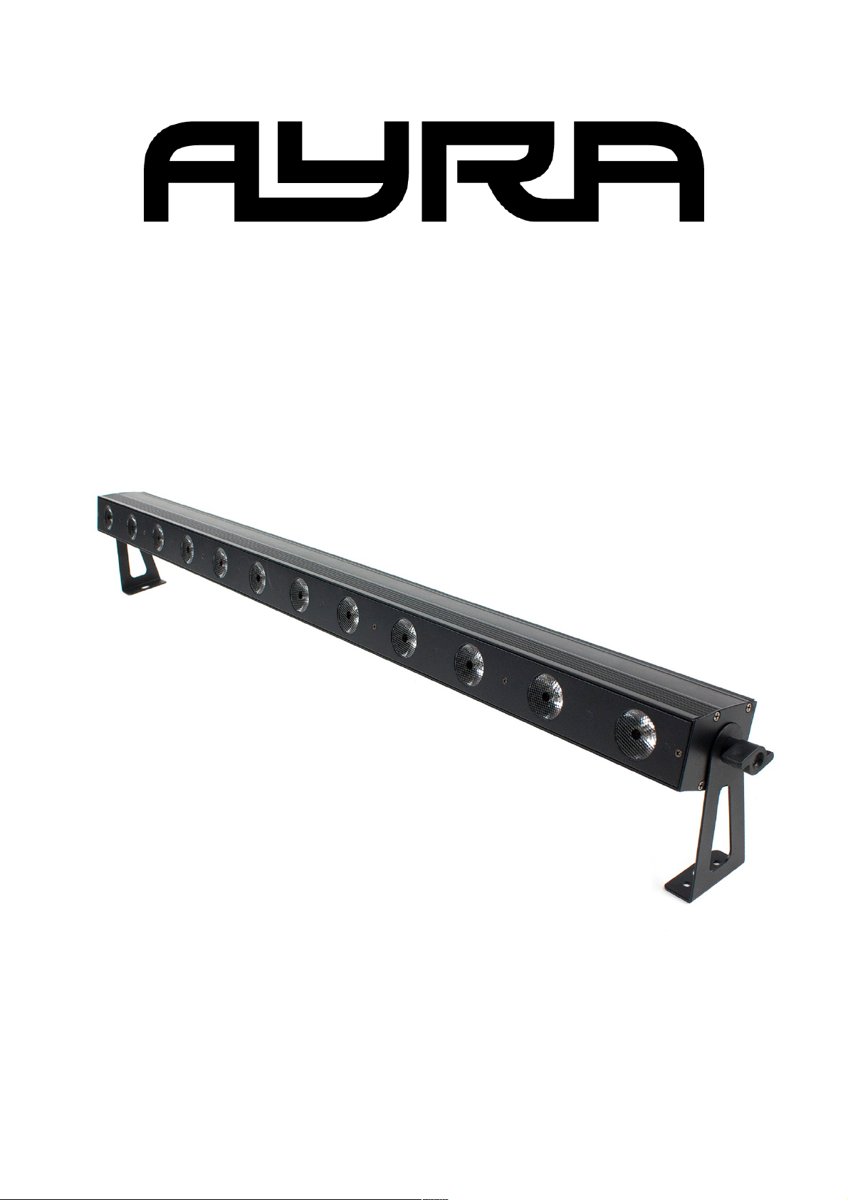
LED Tri-Bar 12
High power LED pixel bar
User manual
All information and illustrations shown in this user manual are subject to change without further notice.
User manual version: 1.0 Creation date + author initials: 02-02-2015 RV Revision date + author initials: 02-02-2015 RV
Page 2
Safety instructions
This unit must be operated by, or under the supervision of an adult. This device is not suitable for children.
Every person involved with the installation, operation and maintenance of this device has to:
- Be qualified
- Follow the instructions of this manual
- Make sure there is no damage caused by transport. If the device seems damaged from the outside, do not
use it and contact your dealer for more information.
- To make sure the device remains in perfect condition and for safe operation, the user must follow the
instructions and warning notes of this user manual.
- Damage caused by improper use or modifications to the device are not covered by the warranty.
- This device does not have any user-serviceable parts inside. This device must be serviced by qualified
technicians.
- The light source of this device is not replaceable. When the light source reaches its end of life, the whole
luminaire must be replaced.
Important notes regarding safety and health:
- Never let the power cord come in contact with other cables. Handle the power cord and all mains
connectors with caution.
- Never remove any warning or informative labels from the unit.
- The ground contact must be connected at all times. Do not cover or remove the ground contact.
- Never leave cables lying around.
- Do not open the device and do not modify any hardware or software.
- Do not insert objects into air vents of this device.
- Do not connect this device to a dimmer pack.
- Do not switch the system on and off frequently, as this will reduce the lifespan of the device.
- Do not drive the inputs of the fixture with a signal greater than required to work at full performance.
All information and illustrations shown in this user manual are subject to change without further notice.
User manual version: 1.0 Creation date + author initials: 02-02-2015 RV Revision date + author initials: 02-02-2015 RV
WARNING!
Always keep this device away from moisture and rain! Hazardous electric shocks may occur!
WARNING!
Only connect this device to a matching power outlet. This device is intended to work on a
specified AC currency. Connecting this device to power outlets with other voltages may result in
permanent damage and possible hazardous situations, such as fire or electric shocks!
WARNING!
Be careful with every operation of this device. Touching live wires inside and outside the unit
may cause hazardous electric shocks!
Page 3
- Only use this device indoors, avoid contact with water, moisture and other liquids. Do not place items filled
with liquids on top of the unit.
- Avoid nearby flames or heat sources, do not place this device near flammable liquids, gas or flammable
items.
- Always disconnect the device when it is not in use for a longer period or time, when servicing is needed, or
when the device needs cleaning.
- Only handle the power cord by its connectors. Never pull the cable to remove a connector from its socket,
as this could lead to damage and electric shocks.
- Always operate this device with a stable AC current.
- Always operate this device with the AC ground wire connected to the electrical system's ground.
- Never use other types of cables than specified in the manual, do not use defective or malfunctioning
cables. Contact your dealer if the included or required cables do not work properly with this device.
- If the device has been exposed to considerable temperature changes (for example, transport from outdoors
to indoors), do not connect the device immediately. Do not activate the unit until it has reached room
temperature, as moisture might build up inside the unit, which may cause short-circuiting and/or electric
shocks.
Guidelines and types of use:
- This device is intended to be used by professionals on stage, in theatres, clubs and similar venues.
- This device is used for light effects and entertainment purposes. This product is not suitable for regular
household room illumination.
- This device is not suitable for use by children and must always be operated by an adult.
- Only use the device when the environment is suitable and will not cause any damage. Do not use the
product in moist or dusty environments, or where long-term damage may occur such as:
- indoor swimming pools where chlorine is used.
- Beaches, where sand and salt are present.
- Outdoors.
- Indoor areas where intense heat sources are present or where the temperature exceeds levels that
are comfortable for humans.
- Use only the included power cable and only connect the device to a suitable power outlet with the correct
output voltage. Connecting the device to a power outlet with the wrong type of voltage or using the product
with a wrong type of power supply may cause permanent damage to the device.
- Avoid shocks and collision during use and transport. Do not transport the device while in use. Avoid brute
force during the installation and operation of this device.
- Familiarise yourself with the functions of the device before use. Do not allow operation of the device by
unskilled or unqualified people.
- Use of the device in other ways than described in this user manual may cause damage and injury. Ayra can
not be held responsible for any damage or injury caused by improper use.
Storage and transport:
- This device is intended for mobile use as well as fixed installations. During transport, use the original
packaging of the product, or a fitting flight case, preferably filled with foam.
- This device is not intended for continuous use. Operation breaks will ensure that the lifespan of the device
is not reduced.
- If the device is not used for a longer period of time, disconnect it from its power source and store it in its
original packaging, or in a fitting flight case.
- Store the device dry and indoors, and do not expose the device to extreme temperature changes.
Housing:
- Inspect the housing of the device frequently. Severe dents, cracks and missing screws should be prevented
at all costs. Do not use the device when the housing is not in optimal condition. Contact your dealer or a
skilled technician when in doubt about the state of the device.
- Check the fixture and screws for corrosion. Corrosion should not be present on the fixture. Contact your
dealer or a skilled technician when corrosion is found on the fixture.
- Every power or signal chassis/connector should be mounted tightly. Do not use the device when connectors
are loose.
- Do not use the power cord if the cores are visible. Contact your dealer for a replacement if needed.
- Prevent the build-up of dust and dirt. Clean the exterior of the fixture every month with a dry or damp cloth.
If the device is intensively used, the cleaning frequency must be increased. Disconnect the fixture when it is
All information and illustrations shown in this user manual are subject to change without further notice.
User manual version: 1.0 Creation date + author initials: 02-02-2015 RV Revision date + author initials: 02-02-2015 RV
Page 4
going to be serviced.
Fuses:
- The main fuse of this device can be found on the rear of the device, usually next to the power inlet.
- Only replace the fuse for a new one of the same type and rating! Do not use a fuse with a higher or lower
rating.
- Do not bridge the fuse in any way, as the fuse is used for protection against electric shocks and shortcircuiting. The fuse is a safety measure to protect your audience from hazardous electric shocks.
- Always replace the fuse cover over the fuse compartment. Do not use tape or other fastening materials to
close the cover. If the fuse holder is broken, contact your local dealer and do not use the fixture.
Symbol clarification:
WEEE: Dispose of this product properly. This product is part of the WEEE directive – the
Waste Electrical and Electronic Equipment directive. The requirements stated in this directive
apply to all manufacturers and producers of electronic equipment in the EU.
Do not dispose of this product together with regular household trash. Contact your local
government for more information about proper disposal and recycling of electronic products in
your region. By recycling this product properly after use, we can work together to enjoy these
products and also protect our environment from being polluted.
CE: The CE mark indicates that the product complies with applicable European directives and
regulations.
All information and illustrations shown in this user manual are subject to change without further notice.
User manual version: 1.0 Creation date + author initials: 02-02-2015 RV Revision date + author initials: 02-02-2015 RV
Page 5
Indoor use only: This device is designed to only be used indoors. The maximum ambient
temperature should not exceed 40 degrees Celsius (104 degrees Fahrenheit)
Box contents
Box contents
1x LED Tri-Bar 12 fixture
1x power cable IEC C13 to Schuko (3x 1mm²)
1x power cable IEC C13 to UK plug (3x 1mm²)
1x hardware pack containing 2 brackets and 2 tightening knobs
Unit and accessory inspection
- Always use the supplied power cable to connect the unit to a power supply. If the cable appears broken or
has visible damage, do not use it.
- If the unit is not going to be used for a longer period of time, disconnect it from the power supply and store it
in a dust-free environment.
- Always check the unit for possible damage before use. If you suspect that something is wrong with the unit,
do not connect it to a power source! When you suspect that your unit is broken or damaged, contact your
local dealer or a certified technician to inspect the unit.
All information and illustrations shown in this user manual are subject to change without further notice.
User manual version: 1.0 Creation date + author initials: 02-02-2015 RV Revision date + author initials: 02-02-2015 RV
Page 6
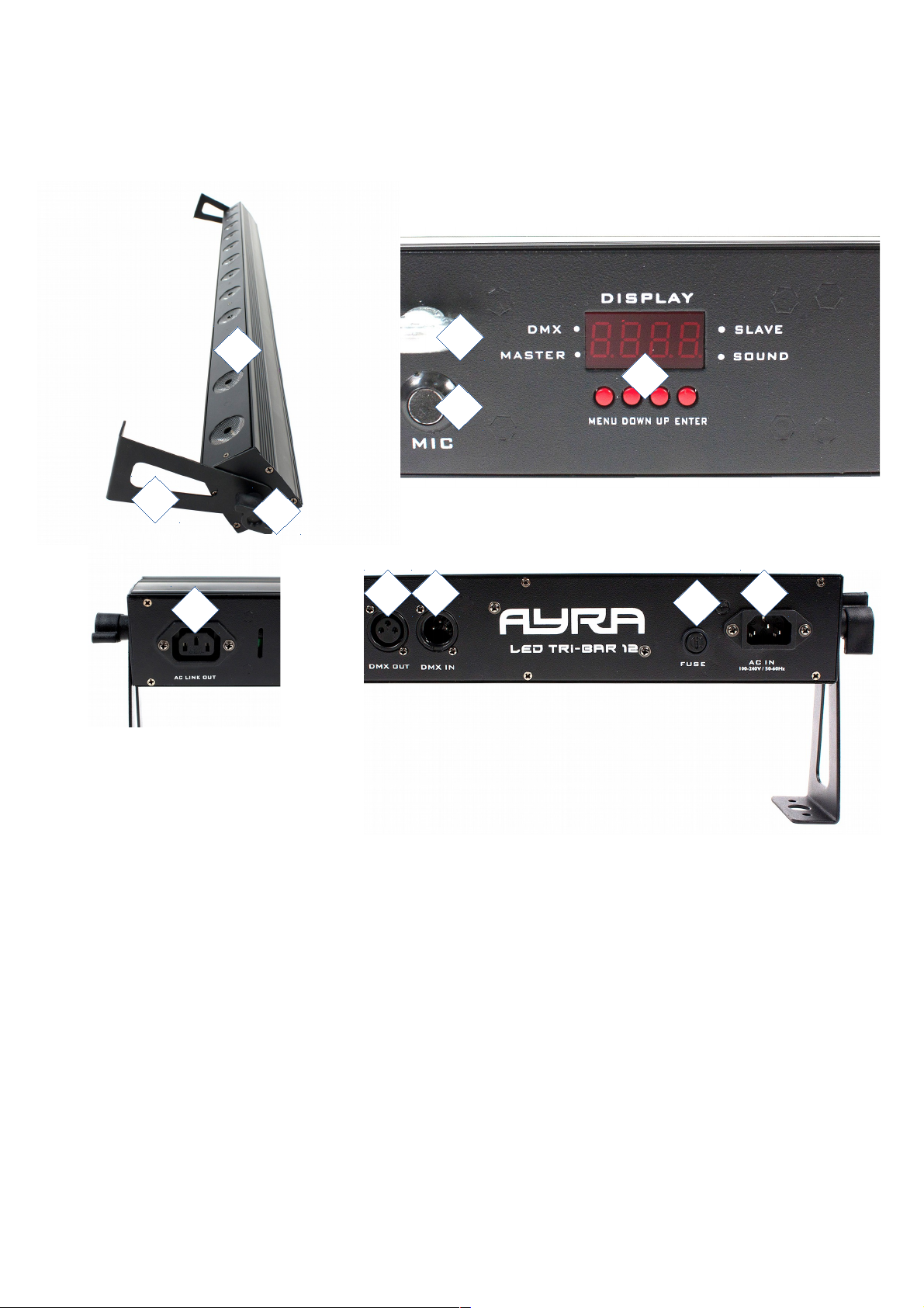
Device overview
1. Beam output
2. Adjustable bracket
3. Tightening knob
4. Safety eyelet for safety cable attachment
5. Built-in microphone for sound-activated mode
6. Menu display with control buttons
7. Power link (IEC C13 chassis)
8. DMX out (3p XLR)
9. DMX in (3p XLR)
10. Fuse compartment
11. Power input (IEC C14 chassis)
All information and illustrations shown in this user manual are subject to change without further notice.
User manual version: 1.0 Creation date + author initials: 02-02-2015 RV Revision date + author initials: 02-02-2015 RV
1
2
3
4
5
6
7
8 9
10
11
Page 7
Setting up the unit
To activate the unit, connect the appropriate included power cable to the unit and to a suitable 230V, 50Hz
power outlet.
The fixture will start up and show the last chosen setting on the display. For a new product, this is usually the
DMX mode with the value set to 001. During start-up the display reads 'Ayra'. After this, the last used mode
will be shown and the settings and values can be changed.
The display shows several settings, each with the possibility of setting several values.
Use the display and the menu buttons on the bottom to set preferences, change settings and scroll through
the menu. “Enter” is used to save a certain setting or preset, press “Menu” for at least 2 seconds to return to
the main menu.
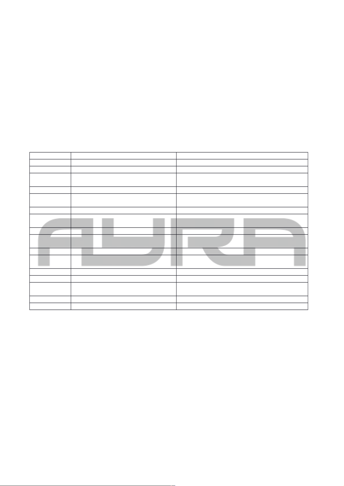
The table below shows an explanation for every feature and value.
display Mode Function
ADDR DMX address setting A001-A512
CHND Channel mode 1CH/3CH1/3CH2/4CH/6CH/7CH/13CH/36CH
SLND Master/slave mode Master (default)
Slave 1 - Slave 2
SHn1 Show mode 1 Auto mode – mix colour. Select speed SP0-9
SHn2 Show mode 2 Auto mode – user-selected colour. Select speed
SP0-9 and select colour COL1-7
COLO Colour preset Full on – Colour preset 1-7
SOUN Sound-controlled mode Sound-controlled mode on/off, overrides
selected speed of SHn1 or SHn2
SENS Sound sensitivity Sound sensitivity 0-100
BALA Colour balance Select colour balance for red, green, blue (50-
255)
BLND LED mode ON-OFF
LED LED display on/off Select display on/off during use (when on, will
shut off after several seconds)
DISP Display inversion Display Inversion, Idsp-dspI
TEST Test mode Self test
CPU Inner test programs CPU check
Code B10 + C10 = working OK
Hour Using time of light Fixture hours, 0 ~ 9999
Ver Software version Only for information
ADDR: DMX address setting, used to determine the DMX starting channel. From this channel on, the fixture
will respond to values, corresponding with the amount of channels that the fixture is occupying. (For
example, when you set the starting address to value 003, the fixture will respond to channels 3, 4, 5 etc.)
CHND: The channel mode of the fixture makes it possible to use the correct channel mode setting for every
application. For simple and basic setups, users may prefer to use the 1CH or 3CH mode. For advanced
setups, users may prefer to choose the 36CH mode to be able to control the colour of every pixel.
SLND: When using the master/slave function, connect 2 or more fixtures with standard 3p XLR male - XLR
female cables. The first fixture in line needs to be set as master, the others as Slave 1 or 2 (synchronised or
mirrored performance in sound-activated mode). This way, the slaves will mimic the behaviour of the master
fixture for amazing synchronised light shows. The default setting of the fixture is master.
SHn1: Show mode 1, which is the auto colour mix mode. When this mode is selected, the internal programs
of the bar are run in a standard order, with several colour changes and effects. When selecting this mode, the
user also has to select the desired speed, which is set by SP0-9. Press enter to select the value and press
All information and illustrations shown in this user manual are subject to change without further notice.
User manual version: 1.0 Creation date + author initials: 02-02-2015 RV Revision date + author initials: 02-02-2015 RV
Page 8
and hold the menu button for 2 seconds to return to the main screen and activate the new values.
SHn2: Show mode 2, which is the set colour mode. When this mode is selected, the internal programs of the
bar are run in a standard order. But as opposed to the first show mode, users can select 1 basic colour with
the COL mode (1-7) and the speed (0-9). When entering the SHn2 mode, use the up and down buttons to
switch between colour and speed values. Press enter to access colour or speed and change the values if
necessary. Press enter to store the new value. Press and hold the menu button for 2 seconds to return to the
main screen and activate the new values.
COLO: Choose from one of the 7 built-in colour presets. Choose red, green, blue, yellow, purple, cyan, white.
SOUN: Activate or disable the built-in sound-controlled mode. When activated, the fixture will respond to the
beat of the music. When the sound-controlled mode is activated, it will override all speed settings of SHn1
and SHn2. When turned off, the selected speed of SHn1 and SHn2 are used.
SENS: The sensitivity of the built-in microphone is adjustable, to optimise the built-in sound-controlled mode.
For example, when your music source (speakers) is placed far away, it is possible to increase the sensitivity
to make sure that the fixture responds to the sound accurately.
BALA: Colour balance. For theatrical applications, users may want to change the colour balance of the bar
so it is more similar to the colours of other lighting fixtures. With this mode, the maximum intensity for each
basic colour (red, green, blue) can be limited from value 50 to 255. When this mode is selected, use the up
and down buttons to scroll between the basic colours and press enter to see the current values. Adjust values
with the up and down buttons and press enter to store changes. The default setting is 255 for each basic
colour.
BLND: Fixture LEDS on/off. For testing purposes it is possible to switch the fixture LEDs on or off. If this
mode is activated, no light will be projected from the pixel bar.
LED: LED display on/off. When using this device in a club or theatre, the environment is mostly dark.
Therefore, it is possible to shut off the LED menu display when it is not in use. Default setting is to ON, which
states that the LED display remains on all the time.
DISP: Display invert version – When using the fixture upside down or vertically, it is possible to flip the
display, so the characters will be shown upside down. This makes reading the status much easier during
maintenance or when changing menu values.
TEST: When this mode is selected, the basic colours are shown in the RGB order. After this, the bar will test
all pixels separately. This will continue in an infinite loop until the user exits the test mode. This mode is used
for maintenance purposes, to check the functionality of the bar, and to see if all pixels and colours work as
they should.
CPU: LED CPU status. Usually, when the bar is working as it should, the status reads B10 and C10. This
means the CPU units are working well. If the CPU reads status 'NG' there is something wrong in the CPU and
the bar needs to be checked by a skilled technician. Contact your local dealer for repairs or replacement of
the fixture if needed.
Hour: The fixture shows how much hours it has been used. This is very practical information for rental
companies, who need to perform service intervals on all fixtures after several hours of performing, to ensure
all fixtures remain in proper working condition.
VER: Software version. Given values are only informative and can not be changed. Users cannot perform
firmware updates to this fixture.
All information and illustrations shown in this user manual are subject to change without further notice.
User manual version: 1.0 Creation date + author initials: 02-02-2015 RV Revision date + author initials: 02-02-2015 RV
Page 9
Operating modes
The LED Tri-Bar 12 offers various operating modes, each with its own advantages. For simple events there
are stand-alone modes, for advanced situations it's possible to create synchronised light shows. You can also
control every feature of the LED Tri-Bar 12 via DMX, in several channel modes. A short description for each
mode can be found below:
Auto:
Automatic light show with a pre-programmed internal show, on a pre-defined speed. Use SHn1 and SHn2
modes to activate the auto modes. The speed of the internal programs can be adjusted from 0 to 9. Use the
COLO mode to activate one of the built-in colour presets for the complete bar.
Sound:
Automatic light show with a pre-programmed internal show, in sync with the music, thanks to an internal
microphone that picks up the beat of the music and changes a step every time a beat is detected. Use the
SENS mode to change the sensitivity of the internal microphone. In this mode, any set speed in the SHn1
and SHn2 modes is overruled and the fixture will change effects in sync with the beat of the music.
Slave:
In master/slave mode, it is possible to link several LED Tri-Bar 12 fixtures together, to create synchronised
light shows in the Auto or Sound mode. The first fixture in the chain must be set in the Auto or Music mode,
and the other fixtures must be set to Slave, so they will mimic the behaviour of the first fixture. The
master/slave function requires 3p XLR male – XLR female cables (not included).
DMX:
The LED Tri-Bar 12 can be connected to a DMX controller with standard 3p XLR male – XLR female cable. In
DMX mode, a DMX terminator must be connected to the last fixture at the end of the DMX chain, to prevent
reflections in the DMX signal, which could cause flickering and unwanted behaviour from your intelligent
fixtures.
A DMX terminator is an XLR connector with a 120-ohm resistor placed between pin 2 and 3 as a bridge.
NOTE: The LED Tri-Bar 12 has several DMX operating modes, some of which offer the Special Show mode.
In this mode, it's possible to select an automatic show program, but also a separate colour. This way, users
can easily select the effect mode of their choice (raindrop effect, flip-flop effect, etc.) and apply a colour of
their choice. This is an easy way to create stunning effects with your LED Tri-Bar 12, that still allows you to
directly adjust colours for your complete light shows.
The LED Tri-Bar 12 can be controlled by DMX with the following channel setups:
1CH mode:
CH1 000-007 no value
008-022 Show 1
023-037 Show 2
038-052 Show 3
053-067 Show 4
068-082 Show 5
083-097 Show 6
098-112 Show 7
113-127 Show 8
128-142 Show 9
143-157 Show 10
158-172 Show 11
173-187 Show 12
188-202 Show 13
203-217 Show 14
218-232 Show 15
233-247 Show 16
248-255 Show 1-16 random
Sound-controlled show select 1-16
All information and illustrations shown in this user manual are subject to change without further notice.
User manual version: 1.0 Creation date + author initials: 02-02-2015 RV Revision date + author initials: 02-02-2015 RV
Page 10
3CH1 mode (RGB mode):
CH1 000-255 Dimmer red 0-100%
CH2 000-255 Dimmer green 0-100%
CH3 000-255 Dimmer green 0-100%
3CH2 mode (Show mode):
CH1 000-100 Standard shows
100-255 Special shows
Standard show selection + Special show
selection
CH2 000-255 Speed selection, applies to both show modes Speed selection slow-fast
CH3 Colour select (only applies when channel 1 value is
larger than 100)
Colour select 1-7
4CH mode:
CH1 000-007 no function
008-247 Show selection 1-16
248-255 Sound controlled mode
Show mode selection
CH2 000-255 Master dimmer 0-100%
CH3 000-007 no function
008-247 strobe slow-fast
248-255 sound controlled strobe
Strobe mode
CH4 000-255 Speed adjustment slow to fast (overruled
when sound mode is active)
6CH mode:
CH1 000-100 Standard shows
100-255 Special shows
Standard show selection + Special show
selection
CH2 000-255 Speed adjustment slow to fast
CH3 000-255 Dimmer red 0-100% (not used during
Standard Show mode)
CH4 000-255 Dimmer green 0-100% (not used during
Standard Show mode)
CH5 000-255 Dimmer blue 0-100% (not used during
Standard Show mode)
CH6 000-255 Strobe mode, slow-fast
7CH mode:
CH1 000-255 Dimmer red 0-100%
CH2 000-255 Dimmer green 0-100%
CH3 000-255 Dimmer blue 0-100%
CH4 000-255 Master dimmer 0-100%
CH5 000-007 no function
008-247 strobe slow-fast
248-255 sound controlled strobe
Strobe mode
CH6 000-007 no function
008-247 Show selection 1-16
248-255 Sound-controlled mode
Show mode selection
CH7 000-255 Speed control slow-fast (only when show
mode 1-16 is active)
All information and illustrations shown in this user manual are subject to change without further notice.
User manual version: 1.0 Creation date + author initials: 02-02-2015 RV Revision date + author initials: 02-02-2015 RV
Page 11
12CH mode:
CH1 000-010 no value
011-255 colour selection
Colour select pixel 1
CH2 000-010 no value
011-255 colour selection
Colour select pixel 2
CH3 000-010 no value
011-255 colour selection
Colour select pixel 3
CH4 000-010 no value
011-255 colour selection
Colour select pixel 4
CH5 000-010 no value
011-255 colour selection
Colour select pixel 5
CH6 000-010 no value
011-255 colour selection
Colour select pixel 6
CH7 000-010 no value
011-255 colour selection
Colour select pixel 7
CH8 000-010 no value
011-255 colour selection
Colour select pixel 8
CH9 000-010 no value
011-255 colour selection
Colour select pixel 9
CH10 000-010 no value
011-255 colour selection
Colour select pixel 10
CH11 000-010 no value
011-255 colour selection
Colour select pixel 11
CH12 000-010 no value
011-255 colour selection
Colour select pixel 12
13CH mode:
CH1 000-255 Dimmer pixel 1 0-100%
CH2 000-255 Dimmer pixel 2 0-100%
CH3 000-255 Dimmer pixel 3 0-100%
CH4 000-255 Dimmer pixel 4 0-100%
CH5 000-255 Dimmer pixel 5 0-100%
CH6 000-255 Dimmer pixel 6 0-100%
CH7 000-255 Dimmer pixel 7 0-100%
CH8 000-255 Dimmer pixel 8 0-100%
CH9 000-255 Dimmer pixel 9 0-100%
CH10 000-255 Dimmer pixel 10 0-100%
CH11 000-255 Dimmer pixel 11 0-100%
CH12 000-255 Dimmer pixel 12 0-100%
CH13 000-255 Master colour selection
All information and illustrations shown in this user manual are subject to change without further notice.
User manual version: 1.0 Creation date + author initials: 02-02-2015 RV Revision date + author initials: 02-02-2015 RV
Page 12
36CH mode:
CH1 000-255 Dimmer pixel 1 red 0-100%
CH2 000-255 Dimmer pixel 1 green 0-100%
CH3 000-255 Dimmer pixel 1 blue 0-100%
CH4 000-255 Dimmer pixel 2 red 0-100%
CH5 000-255 Dimmer pixel 2 green 0-100%
CH6 000-255 Dimmer pixel 2 blue 0-100%
... ... ...
CH31 000-255 Dimmer pixel 11 red 0-100%
CH32 000-255 Dimmer pixel 11 green 0-100%
CH33 000-255 Dimmer pixel 11 blue 0-100%
CH34 000-255 Dimmer pixel 12 red 0-100%
CH35 000-255 Dimmer pixel 12 green 0-100%
CH36 000-255 Dimmer pixel 12 blue 0-100%
All information and illustrations shown in this user manual are subject to change without further notice.
User manual version: 1.0 Creation date + author initials: 02-02-2015 RV Revision date + author initials: 02-02-2015 RV
Page 13
Installation and connection requirements
The Ayra LED Tri-Bar 12 is a versatile product and can be used in many ways. To use this device as
intended and to be sure that the product is used in a safe way, the following requirements must be met
during the setup, installation and connection of the device.
Standing installation
The LED Tri-Bar 12 comes with two small brackets, which make it possible to use the product in a horizontal,
standing position. Even though the stands are stable enough to keep the bar in this position, it is advised to
widen the stand surface for optimal stability, for example by mounting extra floor stands to the LED Tri-Bar 12
brackets. Alternatively, you can use bolts to anchor the bar to the floor. This is especially recommended
during use on stage, where artists, DJs and performers may accidentally kick the bar, thus making it fall over
during performance.
The height of the brackets allows for the use of standard power and XLR cables. It is possible to aim the light
beam straight forward, upward or anywhere in between. Loosen the tightening knobs to adjust the beam
angle and tighten them again to ensure the bar stays aimed in the desired position.
Suspended installation
The LED Tri-Bar 12 comes with two small brackets, which may be used for mobile or permanent installation
to a T-bar, truss setup, wall, ceiling, etc.
For suspended installation where the audience or performers can reach the direct environment of the bar, the
device must be securely mounted using the right hardware.
- For setups such as light stands (t-bars) and truss, the use of G-clamps and half couplers is advised.
- Other ways of installation, such as mounting the bar to a ceiling or wall, require special hardware. As the
construction materials may vary, it is recommended that you contact an expert to select the right mounting
equipment for the installation.
For every suspended installation, the LED Tri-Bar 12 needs to be secured using a proper safety cable. This
prevents the bar from falling if the primary hardware fails for any reason. A safety eyelet is available on the
unit. The safety cable must be able to hold at least 10 times the weight of the bar. Pay attention to the length
of the cable, which should be no longer than 1.2 times the minimum required length. A safety cable that is too
long allows the fixture fall and swing, thus creating additional force on the safety cable and possibly
damaging nearby objects.
Transport and storage
The Ayra LED Tri-Bar 12 can be transported directly after shut-down. As the 12 tri-LED light sources do not
need time to cool down, the device can be stored and transported instantly.
During transport, the device must be securely protected to ensure it stays reliable and in optimal shape.
Always use the original box and packaging material to transport the unit, or a fitting flight case or flight bag if
the device is transported frequently during mobile use.
Power input and output
The LED Tri-Bar 12 is equipped with a power input, as well as a power output (IEC C13/C14). This makes it
possible to daisy-chain both power and DMX for multiple LED Tri Bar 12 fixtures, which may be practical
during use on stage and prevents a cable mess.
Pay attention to the maximum total current of 10 A when using the power outputs. When daisy-chaining
several LED Tri-Bar 12 fixtures, the maximum on a single line should not be more than 25!
After 25 fixtures have been power daisy-chained, a new connection to a wall outlet must be made in order
not to exceed the 10A limit of the IEC C13/C14 connectors.
All information and illustrations shown in this user manual are subject to change without further notice.
User manual version: 1.0 Creation date + author initials: 02-02-2015 RV Revision date + author initials: 02-02-2015 RV
Page 14
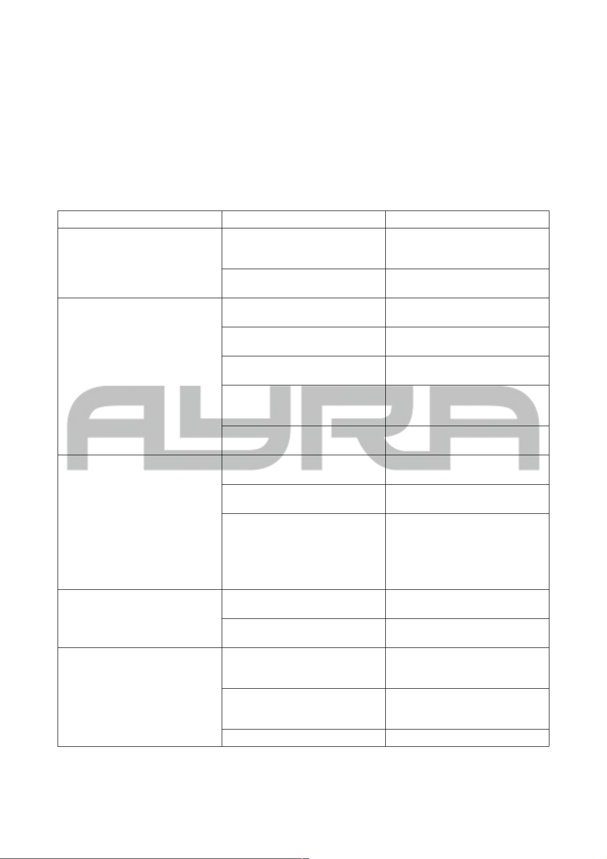
DMX lighting troubleshooting
If you have any problems with DMX lighting, consult this troubleshooting section to solve the difficulties with
your product. If this troubleshooting section does not solve your problem, contact your dealer for more
information and help.
This troubleshooting section contains the most frequent problems and is not a complete collection of possible
faults, defects and solutions. The troubleshooting section applies for DMX controllers, DMX cabling and DMX
lighting fixtures. It is possible that not all described problems, causes and solutions apply to your situation as
product details may vary from product to product.
Problem Possible Cause Solution
The fixture cannot be turned on Blown fuse Check the fuse compartment for
blown fuses and replace them if
necessary
No power cable plugged in Plug in the power supply into a
suitable power outlet
The fixture does not respond to
DMX signals
Wrong DMX address Set the DMX address to the right
value
DMX controller blackout function
activated
Deactivate the blackout function of
your DMX controller
Faulty positioning of the DMX
polarity switch on the controller
Flip the polarity switch on your
DMX controller
No response or DMX activity
signal LEDs active
Check your DMX cables for
possible connector breaks and
replace them if necessary
Wrong working mode Switch the working mode of the
device to DMX mode.
The fixture does not respond to
sound
Wrong operating mode selected. Check if the sound-activated mode
of the fixture is activated.
Microphone sensitivity level is set
too low
Increase the sensitivity level of the
built-in microphone
Speaker placed too far away or
lack of bass
Place your light effect closer to
your speakers (or vice versa)
and/or increase low-frequency
volumes. The microphone will not
be triggered by high-pitched
sounds.
The beam output is very low Dirty/dusty optics Clean the lens and/or other optics
with a dry or damp cloth
Dimmer is not set to full output Set all dimmer levels to 100% on
your DMX console
Sometimes the DMX signal is lost
and/or some fixtures are
flickering / behaving oddly
Faulty/broken DMX cables Check your DMX cables for
possible connector breaks and
replace them if necessary.
Power cable interference on your
DMX signal
Avoid installing the DMX and
(high) power cables parallel to
each other.
No DMX terminator Insert a DMX terminator at the end
All information and illustrations shown in this user manual are subject to change without further notice.
User manual version: 1.0 Creation date + author initials: 02-02-2015 RV Revision date + author initials: 02-02-2015 RV
Page 15
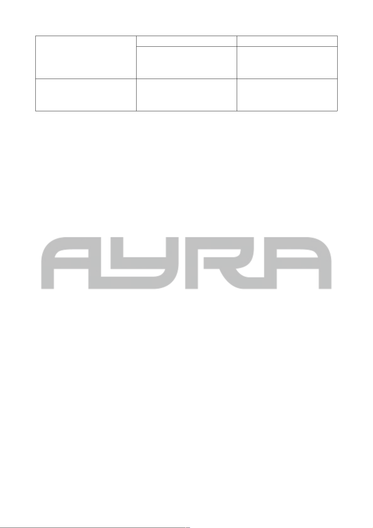
of your DMX chain
Signal loss or distortion in DMX
values
Insert a DMX booster in your DMX
chain after 32 fixtures or less. After
a maximum of 32 fixtures the DMX
signal needs to be refreshed.
The fixture does not respond to all
DMX channels
Wrong DMX channel mode Check the DMX channel mode of
the fixture. If the wrong value is
set, change the channel mode to a
different setting and try again.
All information and illustrations shown in this user manual are subject to change without further notice.
User manual version: 1.0 Creation date + author initials: 02-02-2015 RV Revision date + author initials: 02-02-2015 RV
Page 16
Technical specifications
- powerful LED pixel bar with 12x 3W RGB Tri-LED light source
- compact fixture with robust aluminium housing
- energy-efficient design, power consumption of 50 W max.
- honeycomb lens for optimal brightness and colour mixing, 5,800 lumens @ 1 m, 3,800 lumens @ 2
m!
- over 1 million colour combinations, with RGB LEDs
- DMX, automatic, master/slave and sound-controlled operating modes
- DMX mode with 1CH / 3CH1 / 3CH2 / 4CH / 6CH / 7CH / 13CH / 36CH settings
- automatic mode with Show 1, Show 2 and fixed colour settings:
- show 1: automatic mode with colourful programs, speed to be set by user
- show 2: automatic mode with exciting programs, basic colour and speed to be set by user
- fixed colours: choose from 7 basic colours
- master/slave mode with Slave 1 and Slave 2 settings:
- slave 1: normal slave mode
- slave 2: special slave mode when in sound-controlled mode, with random mirrored effects
- sound-controlled mode: To be combined with the above modes, performance in sync with the beat
of the music
- colour balance system, increase or decrease the max. intensity of basic colours for optimal colour
calibration
- high refresh rate: 2,000/4,500 Hz
- Internal test mode to check all pixels
- CPU test
- fixture working hour readout option
- firmware readout
- 4-button LED menu display with flip option
- LED display shut-down option – display can be shut off when not in use
- included brackets to use the bar standing or suspended
Connectors:
- DMX: 3p XLR male and female
- power: IEC C14 power input and IEC C13 Power Link output
Electronics:
- voltage: AC100-240 V 50/60 Hz
- active power: 50 W max.
- current: 0.4 A
- power factor: 0.555
- fuse: T3AL 250 V (not for power output)
Physical:
- fixture dimensions: 1,008 x 71 x 60 mm
- bracket height: 135 mm
- weight: 5 kg
Included accessories:
- power cable IEC C13 to Schuko (3x 1mm² )
- power cable IEC C13 to UK plug (3x 1mm² )
- hardware kit with 2 brackets and tightening knobs
Technical information:
- maximum ambient temperature (Ta): 40 degrees Celsius
- exterior surface temperature of the device in steady condition during use: 26 degrees Celsius
All information and illustrations shown in this user manual are subject to change without further notice.
User manual version: 1.0 Creation date + author initials: 02-02-2015 RV Revision date + author initials: 02-02-2015 RV
Page 17
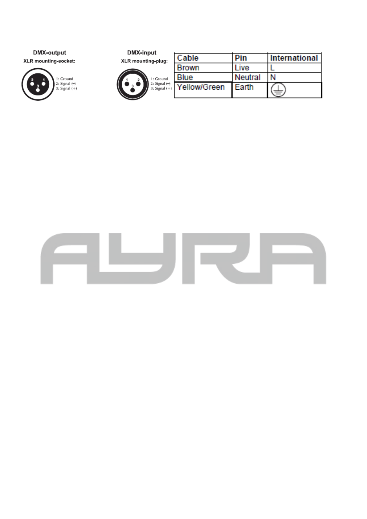
Connectors and wiring schematics:
DMX connectors: Electrical wiring:
All information and illustrations shown in this user manual are subject to change without further notice.
User manual version: 1.0 Creation date + author initials: 02-02-2015 RV Revision date + author initials: 02-02-2015 RV
 Loading...