

Page 1

Instruction Manual
Manual de Instrucciones
Manuel d’Instructions
SB2000M
IMPORTANT MANUAL -- Do not throw away
MANUAL IMPORTANTE -- No lo descarte
MANUEL IMPORTANT -- À Conserver
ENGLISH
ESPAÑOL
WARNING:
Read and follow all Safety Rules and Operating Instructions before
using this product. Failure to do so can result in serious injury.
ADVERTENCIA:
Lea el manual de instrucciones y siga todas las advertencias e
instrucciones de seguridad. El no hacerlo puede resultar en lesiones
graves.
A VERTISSEMENT:
Veuillez lire le manuel d’instructions et bien respecter tous les
avertissements et toutes les instructions de sécurité. Tout défaut
de le faire pourrait entraîner des blessures graves.
Electrolux Home Products
250 Bobby Jones Expressway
Augusta, GA 30907
CopyrightE2002 Electrolux Home Products, Inc.
530163186
6/4/02
FRANÇAIS
Page 2

SAFETY RULES
WARNING:
Safety Rules and Precautions can result in
serious injury.
KNOW YOUR UNIT
Read yourinstruction manual carefully until
S
you completely understand and can follow
all warnings and safety rules before operating the unit.
Restrict unit to users who understand and
D
will follow all warnings and safety rules in
this manual.
WARNING:
ing unit. Remove all debris and hard objects
such as rocks, glass, wir e, etc. that can ricochet, be thrown, or otherwise cause injury or
damage during operation.
Use your unit as a blower for:
Sweeping debris or grass clippings from
D
driveways, sidewalks, patios, etc.
Blowing grassclippings, straw,orleaves into
D
piles, around joints, or between bricks.
Use your unit as a vacuum for:
Picking up dry material such as leaves,
D
grass, small twigs, and bits of paper.
Forbest results during vacuum use, operate
D
your unit at high speed.
Move slowly back and forth over the mate-
D
rial as you vacuum. Avoidforcing the unit
into a pile of debris as this can clog the unit.
Keep the vacuum tube about an inch above
D
the ground for best results.
PLAN AHEAD
Always wear eye protection when operat-
D
ing, servicing, or performing maintenance
on unit. Wearing eye protection will help to
prevent rocks or debris from being blown or
ricocheting into eyes and face which can
result in blindness and/or serious injury.
Eye protection should be marked Z87.
Always wear foot protection. Do not go
D
barefoot or wear sandals.
Always wear respirator or face mask when
D
working with unit in dusty environments.
Secure hair above shoulder length. Secure
D
or remove jewelry, loose clothing, or clothing with loosely hanging straps, ties, tassels, etc. They can be caught in moving
parts.
Do not operate unit when you are tired, ill, up-
D
set, or if you are under the influence of alcohol, drugs, or medication.
Keep children, bystanders, and animals
D
away from work area a minimum of 30 feet
(10 meters) when starting or operating unit.
Do not point the blower nozzle in the direction of people or pets.
HANDLE FUEL WITH CAUTION, IT IS
HIGHLY FLAMMABLE
Eliminate all sources of sparks or flame (in-
D
cluding smoking, open flames, or work that
cancause sparks)intheareas where fuel is
mixed, poured, or stored.
Failure to follow all
Inspect area before start-
-- 2 --
Mix and pour fuel in an outdoor area; store
D
fuel in a cool, dry, well ventilated place; use
an approved, marked container for all fuel
purposes.
Do not smoke while handling fuel or while
D
operating the unit.
Make sure the unit is properly assembled
D
and in good operating condition.
Do not fill fuel tank while engine is hot or
D
running.
Avoid spilling fuel or oil. Wipe up fuel spills
D
before starting engine.
Move at least 10 feet (3meters) away from
D
fuel and fueling site before starting engine.
Always store gasoline in a container ap-
D
proved for flammable liquids.
OPERATE YOUR UNIT SAFELY
WARNING:
opening the vacuum inlet door. The engine
must be stopped and the impeller blades no
longer turning to avoid serious injury from the
rotating blades.
Inspect unit before each use for worn,
D
loose, missing, or damaged parts. Do not
use until unit is in proper working order.
Keep outside surfaces free of oil and fuel.
D
Never start or run engine inside a closed
D
room, building or other unventilated area.
Breathing exhaust fumes can kill.
To avoid static electricity shock, do not
D
wear rubber gloves or any other insulated
gloves while operating unit.
Do not set unit on any surface except a
D
clean, hard area while engine is running.
Debris such as gravel, sand, dust, grass,
etc. could be picked up by the air intake and
thrown out through discharge opening,
damaging unit, property, orcausing serious
injury to bystanders or operator.
Avoid dangerous environments. Do not use
D
in unventilated areas or where explosive
vapors or carbon monoxide build up could
be present.
Do not overreach oruse from unstable sur-
D
faces such as ladders, trees, steep slopes,
rooftops, etc. Keep firmfooting and balance
at all times.
Never place objects inside the blower
D
tubes; always direct the blowing debris
awayfrompeople, animals, glass, and solid
objects such as trees, automobiles, walls,
etc.The forceof aircancauserocks,dirt,or
sticks to be thrown or to ricochet which can
hurt people or animals, break glass, or
cause other damage.
Never run unit without the proper equip-
D
ment attached. When using your unit as a
blower, always install blower tubes. When
using your unit as a vacuum, alwaysinstall
vacuum tubes and vacuum bagassembly.
Make sure vacuum bag assembly is completely zipped.
Check air intake opening, blower tubes,
D
vacuum tubes, and elbow tube frequently,
always with engine stopped and spark
Stop the engine before
Page 3
plug disconnected. Keep vents and discharge tubes free of debris which can accumulate and restrict proper air flow.
Never place any object in the air intake
D
opening as this could restrict proper air flow
and cause damage to the unit.
Never use for spreading chemicals, fertil-
D
izers, orother substances which maycontain toxic materials.
To avoid spreading fire, do not use near
D
leaf or brush fires, fireplaces, barbecue
pits, ashtrays, etc.
Use only for jobs explained in this manual.
D
MAINTAIN YOUR UNIT PROPERLY
Have all maintenance other than the rec-
D
ommended procedures described in the instruction manual performed by an authorized service dealer.
Disconnect spark plug before performing
D
maintenance except for carburetor adjustments.
Use only recommended Snappert/Weed
D
Eater!replacement parts; use of any other
parts may void your warranty and cause
damage to your unit.
Empty fuel tank before storing the unit. Use
D
upfuelleft in carburetor by starting engineand
letting it run until it stops.
Do not use any accessory or attachment
D
other than those recommended by manufacturer for use with your unit.
Do not store the unit or fuel in a closed area
D
where fuel vapors can reach sparks or an
open flame from hot water heaters, electric
motors or switches, furnaces, etc.
Store in a dry area out of reach of children.
D
SPECIAL NOTICE:
tions through prolonged use of gasoline powered hand tools could cause blood vessel or
nerve damage in the fingers, hands, and
joints of people prone to circulation disorders
or abnormal swelling. Prolonged use in cold
weather has been linked to blood vesseldamage in otherwise healthy people. If symptoms
occur such as numbness, pain, loss of
strength, change in skin color or texture, or
loss of feeling in the fingers, hands, or joints,
discontinue the use of this tool and seek
medical attention. An antivibration system
does not guarantee the avoidance of these
problems. Users who operate power tools on
a continual and regular basis must monitor
closely their physical condition and the condition of this tool.
SPECIAL NOTICE:
Exposure to vibra-
For users on U.S. Forest Land and in some states, including California (Public Resources Codes 4442 and
4443), Idaho, Maine, Minnesota, NewJersey,
Oregon, and Washington: Certain internal
combustion engines operated on forest,
brush, and/or grass covered land in the above
areas are required to be equipped with a
spark arresting screen, maintained in effective working order, or the engine must be constructed, equipped, and maintained for the
prevention of fire. Check with your state or local authorities for regulations pertaining to
these requirements. Failure to follow these
requirements is aviolation of the law. This unit
is not factory equipped with a spark arresting
screen; however, a spark arresting screen is
available as anoptional part. If a spark arresting screen is required in your area, contact
your authorized service dealer for the correct
kit. The spark arresting screen, blower tubes,
and nozzles must be assembled to unit to be
in full compliance with regulations.
ASSEMBLY
WARNING:
the impeller blades have stopped turning before opening the vacuum inlet door or attempting to insert or remove the vacuum or
blower tubes. The rotating blades can cause
serious injury. Always disconnect the spark
plug before performing maintenance or accessing movable parts.
WARNING:
assembled, check each step to insure your
unit is properly assembled and all fasteners
are secure. Follow all safety information in
the manual and on the unit.
A standard screwdriver is required for as-
D
sembly.
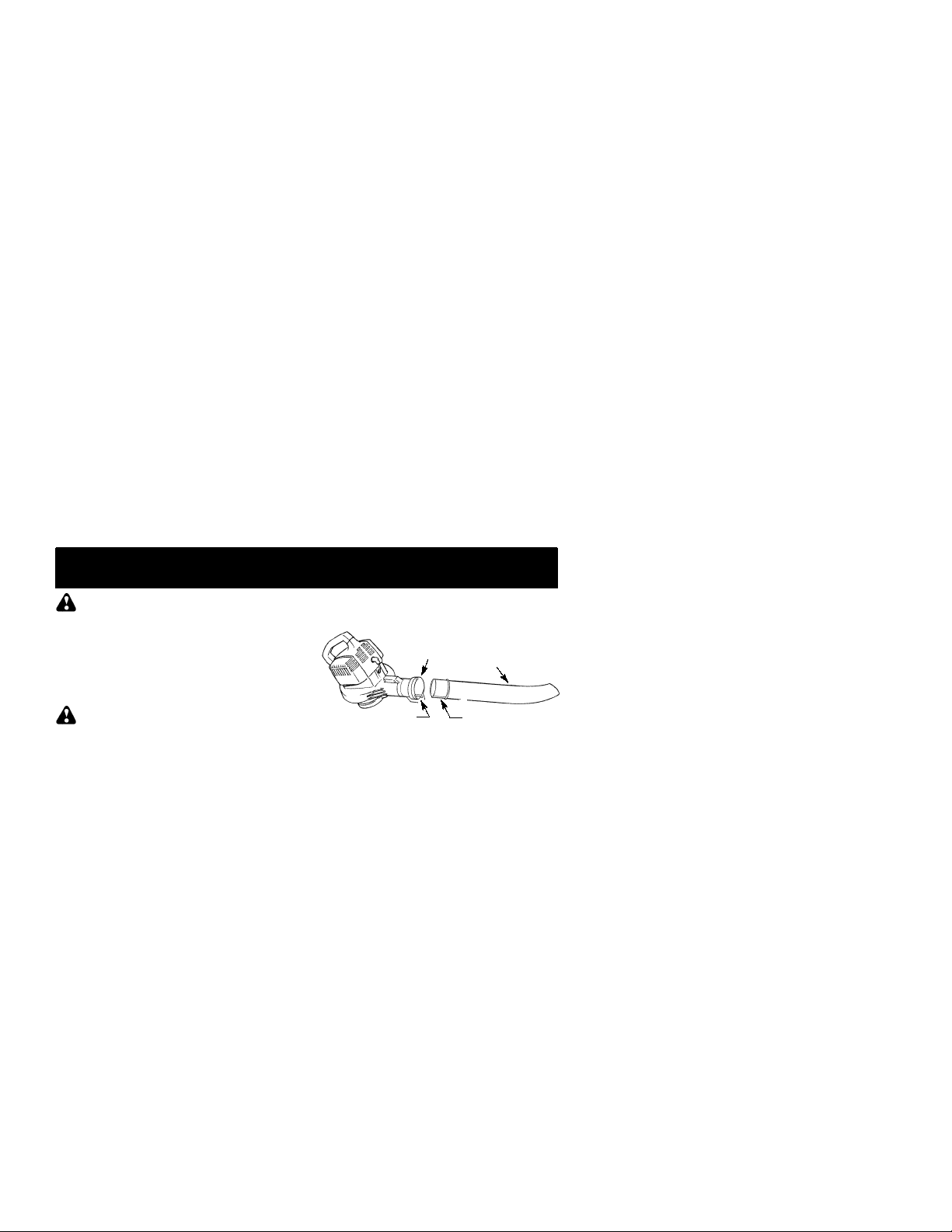
BLOWER TUBE ASSEMBLY
1. Align the rib on the blower tube with the
groove in the blower outlet; slide the tube
into place.
Stop engine and be sure
If you receive your unit
-- 3 --
NOTE:
blower tube to be inserted in blower outlet.
Loosen knob by turning counterclockwise.
2. Secure the tube by turning the knob clock-
3. Toremove the tube, turn the knobcounter-
Knob must be loose enough to allow
Blower
Outlet
Groove
Blower
Tube
Rib
wise.
clockwise to loosen the tube; remove the
tube.
VACUUM BAG ASSEMBLY
1. Open the zipper on the vacuum bag and
insert the elbow tube.
2. Push the small end of the elbow tube
through the small opening in the bag.
Page 4
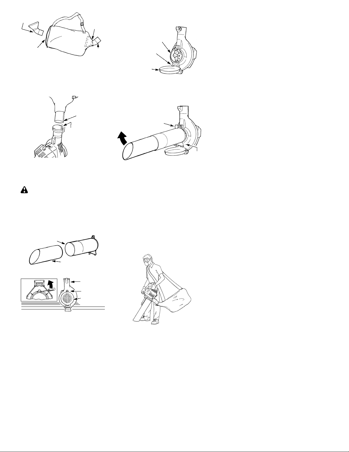
Elbow
Tube
Zipper
Opening
Small
Opening
Rib
4. Hold the vacuum inlet cover open until upper vacuum tube is installed.
Vacuum Inlet
Retaining Post
NOTE:
is flush against the flared area of the elbow
tube, and the rib on the elbow tube is on the
bottom.
3. Closethe zipper onthe bag. Make surethe
4. Remove blower tube from engine.
5. Insert the elbowtube into the blower outlet.
6. Turnknob clockwise tosecure elbowtube.
Make sure edge of the small opening
zipper is closed completely.
Rib
Groove
Make sure elbow tube rib is aligned with
the blower outlet groove.
VACUUM TUBE ASSEMBLY
WARNING:
the impeller blades have stopped turning before opening the vacuum inlet door or attempting to insert or remove the vacuum or
blower tubes. The rotating blades can cause
serious injury.
1. Align the lower vacuum tube as shown.
Push lower vacuum tube into upper vacuum tube.
Upper Vacuum
Tube
Stop engine and be sure
Vacuum
Inlet
Cover
5. Place the hooks on the vacuum tube on
theretaining posts; pivot tube intoposition.
Secure vacuum tube by turning the knob
clockwise until tight.
PIVOT
6. When converting back to the blower feature, make sure latch on the vacuum inlet
cover is securely fastened.
Knob
Hooks
SHOULDER STRAP ADJUSTMENT
1. Hold the unit as shown with the muffler side
facing away from your body and clothes.
2. Pass the shoulder strap over your head
and onto your right shoulder.
3. Extend your left arm toward the rear of the
vacuum bag.
4. Adjust shoulder strap until the vacuum
bag/shoulder strap seam lies between
your thumb and index finger.
5. Make sure air flows freely from the elbow
tube into bag. If bag is kinked, the unit will
not operate properly.
Lower Vacuum Tube
2. Insert a screwdriver into the latch area on
the vacuum inlet cover.
Latch
Area
3. Gently tilt the handle of the screwdriver toward the back of the unit while pulling up
on the vacuum inlet cover with your other
hand.
Blower
Outlet
Latch Area
Vacuum
Inlet Cover
-- 4 --
Page 5

OPERATION
KNOW YOUR BLOWER
READ THIS INSTRUCTION MANUAL AND SAFETY RULES BEFORE OPERATINGYOUR UNIT.
Comparethe illustrationswith your unit to familiarizeyourself with the location of the various controls
and adjustments. Save this manual for future reference.
Lower
Vacuum Tube
Vacuum Bag
Throttle
Lever
Elbow Tube
Blower
Tube
Spark Plug
Upper
Vacuum Tube
Primer Button
Choke Lever
Fuel Mix
Fill Cap
Starter
Rope
Rear
Handle
THROTTLE LEVER
The THROTTLE LEVER is used to select the
desired engine speed and to stop the engine.
Movethe throttle levertothe
full speed operation. Move the throttle lever
tothe
engine, move the throttle lever to the STOP
position.
position for idle speed. Tostopthe
position for
PRIMER BUTTON
The PRIMER BUTTON removes air from the
carbure torand fuel lines and fills them with fuel.
OPERATING POSITION
Eye
Protection
Blower
Vacuum
OPERATING TIPS
While vacuuming or blowing debris, hold
S
the unit with the muffler side facing away
from your body and clothes (seeOPERATING POSITION illustration above).
To reduce the risk of hearing loss
S
associated with sound level(s), hearing
protection is required.
-- 5 --
This allows you to start the engine with fewer
pulls on the starter rope. Activate primer button
bypressing it and allowing it to return to itsoriginal position.
CHOKE LEVER
The CHOKE helps to supply fuel to the engine
to aid in cold starting. Activ ate the choke by
moving the choke lever to the FULL CHOKE
position. After engine attemptstostart, move the
choke lever to the HALF CHOKE position.
Once engine starts, move choke lever to the
RUN position.
To reduce the risk of injury associated with
S
contacting rotating parts, stop the engine before installing or removing attachments. Do
not operate without guard(s) in place.
Operate power equipment only at reasonable
S
hours--not early in the morning or late at night
whenpeople might be disturbed. Comply with
times listedin local ordinances. Usual recommendations are 9:00 a.m. to 5:00 p.m.,
Monday though Saturday.
To reduce noise levels, limit the number of
S
pieces of equipment used at any one time.
To reduce noise levels, operate power
S
blowers at the lowest possible throttle
speed to do the job.
Use rakes and brooms to loosen debris be-
S
fore blowing.
In dusty conditions, slightly dampen sur-
S
faces or use a mister attachment when water is available.
Conserve water by using power blowers
S
instead of hoses for many lawn and garden
applications, including areas such as gutters,
screens, patios, grills, porches, and gardens.
Page 6

Watchout for children, pets, open windows,
S
or freshly washed cars. Blow debris away
safely.
Use the full blower nozzle extension so the
S
air stream can work close to the ground.
After using blowers and other equipment,
S
CLEAN UP! Dispose of debris in trash receptacles.
BEFORE STARTING ENGINE
WARNING:
information in the safety rules before you begin. If you do not understand the safety rules,
do not attempt to fuel your unit. Call
1-800-554-6723
Be sure to read the fuel
.
FUELING ENGINE
WARNING:
when refueling.
This engine is certified to operate on unleaded
gasoline. Before operation, gasoline must be
mixed with a good quality synthetic 2-cycle aircooled engine oildesigned to be mixed ata ratio
of 40:1. Snappert/Weed Eater!brand synthetic oil is recommended. Mix gasoline and oil
at a ratio of 40:1. A 40:1 ratio isobtained by mixing 3.2 ounces of oil with 1 gallon of unleaded
gasoline. DO NOT USE automotive oil or boat
oil. These oils will cause engine damage. When
mixing fuel, follow instructions printed on container.Once oil is added to gasoline, shakecontainermomentarily to assurethatthe fuel isthoroughlymixed. Always read and followthesafety
rules relating to fuel before fueling your unit.
Remove fuel cap slowly
IMPORTANT
Experience indicates that alcohol blended
fuels (called gasohol or using ethanol or
methanol) can attract moisture which leads to
separation and formation of acids during
storage. Acidic gas can damage the fuel
systemofanengine while in storage. T oavoid
engine problems, empty the fuel system
before storage for 30days or longer. Drain the
gastank, startthe engine and let it run until the
fuel lines and carburetor are empty.Usefresh
fuel next season. Never use engine or
carburetor cleaner products in the fuel tank or
permanent damage may occur.
TO STOP THE ENGINE
To stop the engine, move the throttle lever
D
to the STOP position.
BEFORE STARTING THE ENGINE
WARNING:
the tubes are secure before using the unit.
Fuel engine. Move at least 10 feet (3 me-
D
ters) away from the fueling site.
Hold the unit in the starting position as
D
shown. Make sure the blower end is directed away from people, animals, glass,
and solid objects.
YouMUSTmakesure
STARTING POSITION
Blower
Vacuum
WARNING:
holdtheunit as illustrated.Donot setunitonany
surfaceexcept a clean, hard area whenstarting
engine or while engine is running. Debris such
as gravel, sand, dust, grass, etc. could be
picked up by the air intake and thrown out
through the discharge opening, damaging the
unit or property,or causing serious injury to bystanders or the operator.
When starting engine,
ST ARTING A COLD ENGINE (or a
warm engine after running out of
fuel)
1. Move throttle lever to the position.
2. Move choke lever to the FULL CHOKE
position.
3. Slowly press the primer button 8 times.
Throttle Lever
4. Pull starter rope sharply until engine attempts to run, but no morethan 5 pulls (below 30_F, 8 pulls).
If engine attempts to start before the
NOTE:
th
5
pull, go to next step immediately.
5. Move the choke lever to the HALF
CHOKE position.
6. Pull the starter rope sharply until the engine runs, but no more than 5 pulls (below
30_F, 10 pulls).
7. After a 5 second warm--up, move the
choke lever to the RUN position.
8. Allow the unit to run for 30 more seconds
at the RUN position before moving the
throttle lever to
If engine has not started after 5 pulls (at HALF
CHOKE),repeat STAR TINGA COLDENGINE
procedure. If engine still does not start, proceed
to STARTING A FLOODED ENGINE.
9. T ostop the engine, move the throttle leverto
the STOP position.
Primer Button
Choke Lever
position.
-- 6 --
Page 7

STARTING A WARM ENGINE
1. Move throttle lever to the position.
2. Pull starter rope sharply until engine runs,
but no more than 5 pulls.
:
If engine has not started, pull starter
NOTE
rope 5 more pulls. If engine still does not run,
it is probably flooded.
3. T ostop the engine, move the throttle leverto
the STOP position.
MAINTENANCE
WARNING:
unless engine and muffler are cold. A hot
muffler can cause serious burns.
WARNING:
the impeller blades have stopped turning before opening the vacuum inlet door or attempting to insert or remove the vacuum or
blower tubes. The rotating blades can cause
serious injury. Always disconnect the spark
plug before performing maintenance or accessing movable parts.
GENERAL RECOMMENDATIONS
Thewarranty on thisunit does not coveritems
that have been subjected to operator abuse
or negligence. To receive full value from the
warranty, the operator must maintain unit as
instructed in this manual. V arious adjustments will need to be made periodically to
properly maintain your unit.
CHECK FOR LOOSE
FASTENERS AND PARTS
Spark Plug Boot
S
Air Filter
S
Housing Screws
S
Muffler
S
CHECK FOR DAMAGED OR WORN
PARTS
Contact an authorized service dealer for replacement of damaged or worn parts.
Fuel Tank -- Do not use unit if fuel tankshows
S
signs of damage or leaks.
Vacuum Bag -- Do not use vacuum bag if it
S
is torn or damaged.
INSPECT AND CLEAN UNIT AND
DECALS
After each use, inspect complete unit for
S
loose or damaged parts. Cleanthe unit and
decals using a damp cloth with a mild detergent.
Wipe off unit with a clean dry cloth.
S
Avoid touching muffler
Stop engine and be sure
STARTING A FLOODED ENGINE
Flooded engines can be started by placing the
choke lever in the RUN position. Move throttle
lever to the fast position
until engine starts. After engine starts, move the
throttleleverto the slow position
engine to idle.
Starting could require pulling the starter rope
many times depending on how badly the unit is
flooded.
If unit still doesn’t start refer to the TROUBLESHOOTING TABLE or call 1-800-554-6723
; then, pull rope
to allow
.
CLEAN AIR FILTER
Air Filter
Cover
Cleaning the air filter:
A dirty air filter decreases engine performance and increases fuel consumption and
harmful emissions. Always clean or replace
air filter after every 5 hours of operation or
yearly, whichever comes first.
1. Clean the cover and the area around it to
2. Remove parts as illustrated.
NOTE:
flammable solvent. Doing so can create a fire
hazard or produce harmful evaporative emissions.
3. Wash the filter in soap and water.
4. Allow filter to dry.
5. Apply a few drops of oil to the filter;
6. Replace parts.
Air Filter
keep debris from falling into the carburetor
chamber when the cover is removed.
Donot clean filter in gasoline orother
squeeze filter to distribute oil.
Screws
REPLACE SPARK PLUG
Replace spark plug each year to ensure the
engine starts easier and runs better. Set
spark plug gap at 0.025 inch. Ignition timing is
fixed, nonadjustable.
1. Twist, then pull off spark plug boot.
2. Remove spark plug from cylinder and discard.
3. Replace with Champion RCJ-6Y spark
plug and tighten securely with a 3/4 inch
socket wrench.
4. Reinstall the spark plug boot.
-- 7 --
Page 8

REPLACE FUEL FILTER
Toreplace fuel filter, drainunit byrunning it dry
of fuel, then remove fuel cap/retainer assembly from tank. Pull filter from tank and remove
it from the fuel line. Install new fuel filter onfuel
line; reinstall parts.
Fuel Line
Fuel Filter
CHECK MUFFLER MOUNTING
SCREWS
Once each year, ensure muffler mounting
screws are secure and tightened properly to
prevent damage.
STORAGE
WARNING:
steps after each use:
Allow engine to cool, and secure the unit
S
before storing or transporting.
Store unit and fuel in a well ventilated area
S
where fuel vapors cannot reach sparks or
open flames from water heaters, electric
motors or switches, furnaces, etc.
Store unit with all guards in place. Position
S
unit so that any sharp object cannot accidentally cause injury.
Store unit and fuel well out of the reach of
S
children.
SEASONAL STORAGE
Prepare unit for storage at end of season or if
it will not be used for 30 days or more.
If your unit is to be stored for a period of time:
Clean the entire unit before lengthy stor-
S
age.
Store in a clean dry area.
S
Lightly oil external metal surfaces.
S
FUEL SYSTEM
Under FUELING ENGINE in the OPERATION section of this manual, see message labeledIMPORTANT regarding the use of gasohol in your engine.
Perform the following
Mounting
Screw
Muffler Cover
Screws
1. Loosen and remove the 2 screws fromthe
muffler cover.
2. Remove the muffler cover.
3. Tighten the 2 muffler mounting screws securely.
4. Reinstall muffler cover and 2 screws.
Tighten securely.
Holes
CARBURETOR ADJUSTMENTS
Yourcarburetor is equipped with limiter caps.
Adjusting the carburetor is a complicated
task. We recommend that you take your unit
to an an authorized service dealer. Damage
will occur if you turn the needles beyond the
limiter stops.
Fuel stabiliz er is an acc ep table alternative in
minimizing the formation of fuel gum deposits
during storage. Add stabilizer to gasoline in fuel
tank or fuel storage container. Follow the mix
instructions found on stabilizer container. Run
engine at least 5 minutes after adding stabilizer.
ENGINE
Remove spark plug and pour 1 teaspoon of
S
40:1, 2-cycle engine oil (air cooled) through
the spark plug opening. Slowly pull the
starter rope 8 to 10 times to distribute oil.
Replace spark plug with new one of recom-
S
mended type and heat range.
Clean air filter.
S
Check entire unit for loose screws, nuts,
S
and bolts. Replace any damaged, broken,
or worn parts.
At the beginning of the next season, use
S
only fresh fuel having the proper gasoline to
oil ratio.
OTHER
Do not store gasoline from one season to
S
another.
Replace your gasoline canif it starts torust.
S
-- 8 --
Page 9

TROUBLESHOOTING TABLE
WARNING:
recommended remedies below other than remedies that require operation of the unit.
TROUBLE
Engine will not
start.
Engine will not
idle properly.
Engine will not
accelerate,
lacks power, or
dies under a
load.
Engine smokes
excessively.
Engine runs hot.
Alwaysstop unit and disconnect spark plug before performing any of the
CAUSE REMEDY
1. Engine flooded.
2. Fuel tank empty.
3. Spark plug not firing.
4. Fuel not reaching
carburetor.
5. Compression low.
1. Fuel not reaching
carburetor.
2. Carburetor requires
adjustment.
3. Crankshaft seals worn.
4. Compression low.
1. Air filter dirty.
2. Fuel not reaching
carburetor.
3. Spark plug fouled.
4. Carburetor requires
adjustment.
5. Carbon build up.
6. Compression low.
1. Choke partially on.
2. Fuel mixture incorrect.
3. Air filter dirty.
4. Carburetor requires
adjustment.
1. Fuel mixture incorrect.
2. Spark plug incorrect.
3. Carburetor requires
adjustment.
4. Carbon build up.
1. See “Starting a Flooded Engine”
in Operation section.
2. Fill tank with correct fuel mixture.
3. Install new spark plug.
4. Check for dirty fuel filter; replace.
Check for kinked or split fuel line;
repair or replace.
5. Contact an authorized service dealer.
1. Check for dirty fuel filter; replace.
Check for kinked or split fuel line;
repair or replace.
2. See “Carburetor Adjustment” in
Service and Adjustments section.
3. Contact an authorized service dealer
4. Contact an authorized service dealer.
1. Clean or replace air filter.
2. Check for dirty fuel filter; replace.
Check for kinked or split fuel line;
repair or replace.
3. Clean or replace spark plug
and re-gap.
4. See “Carburetor Adjustment” in
Service and Adjustments section.
5. Contact an authorized service dealer.
6. Contact an authorized service dealer.
1. Adjust choke.
2. Empty fuel tank and refill with
correct fuel mixture.
3. Clean or replace air filter.
4. See “Carburetor Adjustment” in
Service and Adjustments section.
1. See “Fueling Engine” in Operation
section.
2. Replace with correct spark plug.
3. See “Carburetor Adjustment” in
Service and Adjustments section.
4. Contact an authorized service dealer.
-- 9 --
Page 10

LIMITED WARRANTY
ELECTROLUX HOME PRODUCTS, INC.,
warrantsto theoriginal purchaserthat each new
Snapper
free from defects in material and workmanship
and agrees to repair or replace under this warranty any defective gasoline product or attachment as follows from the original date of purchase
2 YEARS- -
household purposes.
90 DAYS --
commercial, professional, or income producing
purposes.
30 DAYS --
purposes.
This warranty is not transferable and does not
cover damage or liability caused by improper
handling, improper maintenance, or the use of
accessories and/or attachments not specifically
recommended by
PRODUCTS, INC.,
this warranty does not cover tune-ups, spark
plugs, filters, starter ropes, starter springs, cutting line, orrotating head partsthat willwearand
requirereplacementwith reasonable use during
the warranty period. This warranty does not
brand gasoline tool or attachmentis
tttt
.
Parts and Labor, when used for
Parts and Labor, when used for
Parts and Labor, if used for rental
ELECTROLU X HOME
for this tool. Additionally,
U.S. EPA
EMISSION CONTROL WARRANTY STATEMENT
YOUR WARRANTY RIGHTS AND OBLIGATIONS:
Protection Agency and POULAN/WEED
EATER, DIVISION OF WCI OUTDOOR
PRODUCTS, INC., are pleased to explain the
emissions control system warranty on your
year 2001--2004 small off--road engine.
POULAN/WEED EATER must warrant the
emission control system on your small off-road engine for the periods of time listed below provided there has been no abuse, neglect, or improper maintenance of your small
off--road engine. Your emission control systemincludes parts such as the carburetor and
the ignition system. Where a warrantable
condition exists, POULAN/WEED EATER
will repair your small off--road engine at no
cost to you. Expenses covered under warranty include diagnosis, parts and labor.
MANUFACTURER’S WARRANTY COVERAGE:
engine (as listed under Emissions Control
Warranty Parts List) is defective ora defect in
the materials or workmanship of the engine
causes the failure of suchan emission related
part, the part will be repaired or replaced by
POULAN/WEED EATER.
RANTY RESPONSIBILITIES:
off--road engine owner, you are responsible
for the performance of the required maintenance listed in your instruction manual. POULAN/WEED EATER recommends that you
retain all receipts covering maintenance on
your small off--road engine, but POULAN/
WEED EATER cannot deny warranty solely
for the lack of receipts or for your failure to en-
The U. S. Environmental
Ifany emissions related part onyour
OWNER’S WAR-
As the small
-- 10 --
cover predelivery setup or normal adjustments
explained in the instruction manual.
THIS WARRANTY GIVES YOU SPECIFIC
LEGAL RIGHTS, AND YOU MAY HAVE
OTHER RIGHTS WHICH VARY FROM
STATE TO STATE.
NO CLAIMS FOR CONSEQUENTIAL OR
OTHER D AM AGES WILL BE ALLOWED,
AND THER E AR E N O OTHER EXPRESS
WARR ANTIES EXCEPT THOSE EXPRESSL Y STIPULATED HEREIN.
SOME STATES DO NOT ALLOW LIMITATIONS ON HOW LONG AN IMPLIED WARRANTY LASTS OR TH E EXC L USION OR
LIMITATIONS OF INCIDENTAL OR CONSEQUENTIAL DAMAGES, SO TH E ABOVE
LIMITATIONS OR EXCLUSION MAY NOT
APPLY TO YOU.
The policy of
DUCTS, INC.,
products. Therefore,
PRODUCTS, INC.,
change, modify, or discontinue models, designs, specifications, and accessories of all
products at any time without notice or obligation
to any purchaser.
sure the performance of all scheduled maintenance. As the small off--road engine owner, you should be aware that POULAN/
WEED EATER may deny you warranty coverage if your small off--road engine or apart of
it has failed due to abuse, neglect, improper
maintenance, unapproved modifications, or
the use of parts not made or approved by the
original equipment manufacturer. You are responsible for presenting your small off--road
engine to a POULAN/WEED EATER authorized repair center as soon as a problem exists. Warranty repairs should be completed in
a reasonable amount of time, not to exceed
30days. Ifyou have any questions regarding
your warranty rights and responsibilities, you
should contact your nearest authorized servicecenter orcall POULAN/WEED EATERat
1--800--554--6723.
MENCEMENT DATE:
begins on the date the small off--road engine
is purchased.
This warranty shall be for a period of two
yearsfrom the initial date ofpurchase.
IS COVERED: REPAIR OR REPLACEMENT OF PARTS.
any warranted part will be performed at no
charge to the owner at an approved POULAN/WEED EATER servicing center. If you
have any questions regarding your warranty
rights and responsibilities, youshould contact
your nearest authorized service center orcall
POULAN/WEED EATER at
1--800--554--6723.
Any warranted part which isnot scheduled for
replacement as required maintenance, or
ELECTROLU X HOME PRO-
is to continuously improve its
ELECTROLU X HOME
reserves the right to
WARRANTY COM-
The warranty period
LENGTH OF COVERAGE:
WHAT
Repair or replacement of
WARRANTY PERIOD:
Page 11

which is scheduled only for regular inspection
to the effect of ”repair or replace as necessary” shall be warranted for2 years. Any warranted part which is scheduled for replacement as required maintenance shall be warranted for the period of time up to the first
scheduled replacement point for that part.
DIAGNOSIS:
charged for diagnostic labor which leads to
the determination that a warranted part is defective if the diagnostic work is performed at
an approved POULAN/WEED EATER servicing center.
AGES:
able for damages to other engine components caused by the failure of a warranted
part still under warranty.
COVERED:
glect, or improper maintenance are not cov-
ADD--ON OR MODIFIED PARTS:
ered.
use of add--on or modified parts can be
grounds for disallowing a warranty claim.
POULAN/WEED EATER is not liable tocover
failures of warranted parts caused by the use
This engine is certified to be emissions compliant for the following use:
Moderate (50 hours)
Intermediate (125 hours)
Extended (300 hours)
The owner shall not be
POULAN/WEED EATER may be li-
CONSEQUENTIAL DAM-
WHAT IS NOT
All failures caused byabuse, ne-
ofadd--on ormodified parts.
CLAIM:
If you have any questions regarding
your warranty rights and responsibilities, you
should contact your nearest authorized servicecenter orcall POULAN/WEED EATERat
1--800--554--6723.
RANTY SERVICE:
pairs shall be provided at all POULAN/WEED
EATER service centers. Call
1--800--554--6723.
PLACEMENT AND REPAIR OF EMISSION
RELATED PARTS:
EATER approved replacement part used in
the performance of any warranty maintenance or repair on emission related parts will
be provided without charge to the owner if the
part is under warranty.
TROL WARRANTY PARTS LIST:
tor, Ignition System: Spark Plug (covered up
The
to maintenance schedule), Ignition Module.
MAINTENANCE STA TEMENT:
responsible for the performance of all required maintenance as defined in the instruction manual.
WHERE TO GET WAR-
Warranty services or re-
HOWTO FILE A
MAINTENANCE, RE-
Any POULAN/WEED
EMISSION CON-
Carbure-
The owner is
-- 11 --
 Loading...