

Page 1

WE MAKE
WATER WORK
Pump Catalog
January 2019
Page 2

A.Y. McDonald Mfg. Co.
2
800.292.2737 | FAX 800.832.9296 | sales@aymcdonald.com | aymcdonald.com
1-19
Page 3

MISSION STATEMENT
The mission of A.Y. McDonald Mfg. Co. in the words of our founder is
“To make good products and to sell them honestly.”
We, the stockholders and employees, accomplish this by extending the McDonald family culture
through excellent customer service and by focusing on our customers’ needs.
WHO’S THE BOSS?
Here’s a question I’ll bet you could ask a thousand working people and never get the right answer. The
question is:
There’s only one boss, and whether a person shines shoes for a living or heads up the largest corporation
in the world, the boss remains the same.
The customer is the person who pays everyone’s salary and who decides whether a business is going to
succeed or fail. The customer doesn’t care if a business has been around a hundred years. The minute
it starts treating them badly, the customer will put it out of business.
This boss, the customer, has bought and will buy everything you have or will ever have. The customer has
bought all of your clothes, your home, your car, your children’s education, and your vacation. They pay all
of your bills and they pay them in exact proportion to the way you treat them.
The man who works deep inside a big plant on an assembly line might think he’s working for the company
that writes his pay check, but he is not. He’s working for the person who buys the product at the end
of the line, the customer. In fact, this customer can re everyone in the company from the president on
down. And they can do it by simply spending their money someplace else. This is one of the reasons why
taking pride in the work we do is so important to us personally. Doing an exceptionally good job will not
only bring joy and satisfaction, it will help get more customers, keep the ones we’ve got, and ensure that
we continue to get a pay check from our bosses.
“Who’s The Boss?”
It’s The Customer!
Some of the largest companies that had ourishing businesses a few
years ago are no longer in existence. They couldn’t - or didn’t - satisfy the
customer. They forgot who the boss really was!
At A.Y. McDonald we remind ourselves every day that the customer is
the boss. It’s one of our core values and the reason we provide the
best customer service in the business.
3
Page 4
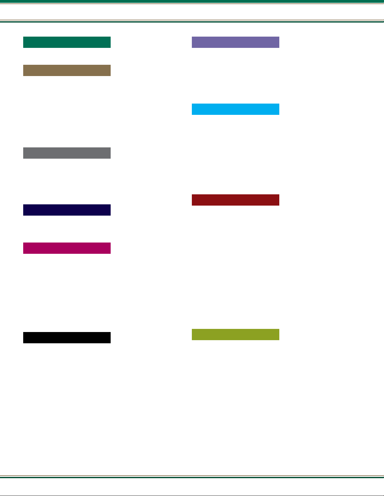
Table of Contents
Table of Contents
Page
Pump Basics
General Information .................................................................. 7-22
Submersible Pumps
Submersible Pumps .............................................................. 23-106
21000 Series ........................................................................... 24-37
22000 Series ........................................................................... 38-52
23000 Series ........................................................................... 53-65
24000 Series (5 - 25 GPM) ...................................................... 66-79
24000 Series (35 - 80 GPM) .................................................... 80-91
26000 Series - All Stainless Steel ......................................... 92-105
Bottom Suction Pump..................................................................106
4” Motors, Controls & Accessories
4” Motors & Controls ........................................................... 107-118
4” A.Y. McDonald Submersible Motors ................................. 108-115
A.Y. McDonald Control Boxes ...............................................116-117
Starter Kits & Pumptec................................................................118
Submersible Pump Accessories
Pump Accessories ............................................................... 119-124
Pressure Master
Pressure Master .................................................................. 125-144
Monodrive............................................................................ 128-131
SubDrive 15 / 75 ................................................................. 132-134
SubDrive 20 / 100 ............................................................... 135-137
Subdrive 30 / 150................................................................ 138-140
SubDrive 50 / 300 ............................................................... 141-143
SubDrive UT2W ............................................................................144
Page
6” , 8”, & 10” Motors & Controls
Motors & Controls................................................................ 167-182
6”, 8”, & 10” Submersible Motors & Technical Information
Control Panels & Deluxe Control Boxes ........................................181
Starter Kits ..................................................................................182
.. 168-180
Pressure Tanks
Pressure Tanks .................................................................... 183-190
How to .........................................................................................184
Tank Sizing ..................................................................................185
Features & Benets .....................................................................186
Water Well Tanks .........................................................................187
Expansion Tanks - Potable Water ................................................188
Expansion Tanks - Hydronic.........................................................189
Jet Pumps
Jet Pumps............................................................................ 191-212
Installations ................................................................................192
Features & Motors .......................................................................193
8100 Series ......................................................................... 194-195
8200 Series ......................................................................... 196-197
8300 Series - E-Series......................................................... 198-199
8500 Series ......................................................................... 200-201
8600 Series ......................................................................... 202-203
1000 Series ......................................................................... 204-205
1500 Series ......................................................................... 206-207
Nema & Square Flange Motors ............................................ 208-209
Jet Ejectors & Adapters - Flanges........................................ 210-211
Jet Pump Accessories ..................................................................212
6”, 8”, & 10” Pump Ends
6”, 8”, & 10” Pump Ends .................................................... 145-166
How to Order................................................................................147
90 GPM................................................................................ 149-150
150 GPM.............................................................................. 151-152
230 GPM.............................................................................. 152-153
300 GPM.............................................................................. 154-155
400 GPM.............................................................................. 156-157
500 GPM.............................................................................. 158-159
650 GPM.............................................................................. 160-161
800 GPM.............................................................................. 162-163
1100 GPM............................................................................ 164-165
4
800.292.2737 | FAX 800.832.9296 | sales@aymcdonald.com | aymcdonald.com
DuraMACTM Booster Pumps
TM
DuraMAC
How to Order - Residential / Light Commercial ...........................216
How It Works - Residential / Light Commercial ...........................217
E-Series Booster Pump ........................................................ 218-219
Residential Booster ............................................................. 220-221
Light Commercial & Irrigation ............................................. 222-223
Dual Mode Modular ............................................................. 224-225
Dual Mode Simplex .............................................................. 226-227
Dual Mode Duplex................................................................ 228-229
How to Order - Vertical Multistage Variable Speed Systems ........230
How It Works - Vertical Multistage Variable Speed Systems ........231
Vertical Multistage Variable Speed - Simplex ...................... 232-233
Vertical Multistage Variable Speed - Duplex ........................ 234-235
Vertical Multistage Variable Speed - Triplex ........................ 236-237
Technical Information & Performance Curves .....................238-245
Booster Pumps ................................................... 213-246
1-19
Page 5
Page
Irrigation & Booster Pumps
Page
Pump Repair Parts
Pit Setters
Irrigation & Booster Pumps ................................................. 247-260
Superbooster ....................................................................... 248-251
92000 & 93000 Series - Workhorse ..................................... 252-253
84000 Series ....................................................................... 254-255
1500XSW Series ..........................................................................256
8600SW Series ............................................................................257
E-Series 89000 Series ......................................................... 258-259
Sump, Sewage, & Efuent Pumps
Sump, Sewage, & Efuent Pumps ....................................... 261-292
How to Order................................................................................263
Utility Pumps...............................................................................264
Sump Pumps ....................................................................... 265-277
Efuent Pumps.................................................................... 278-281
Sewage Pumps .................................................................... 282-284
Sewage Packages................................................................ 285-289
Sump Pump Backup ....................................................................290
Guardian .....................................................................................291
Sump, Sewage, & Efuent Accessories........................................292
Wastewater Pumps
Wastewater Pumps .............................................................. 293-316
Efuent Pumps.................................................................... 296-299
Thermoplastic - Efuent...................................................... 300-303
Sewage Ejector Pumps ........................................................ 304-309
Grinder Pumps .................................................................... 310-313
Pumpmaster & Alarms ........................................................ 314-315
Basin, Check Valves, & Grinder Accessories ................................316
Pump Repair Parts .............................................................. 347-362
Motor Control Components ..........................................................348
Handymac ...................................................................................349
8100 / 8200 Series ......................................................................350
E-Series 8300..............................................................................351
8500 / 8600 Series ......................................................................351
1000 / 1500 Series .............................................................. 352-353
92000 / 93000 Series ..................................................................354
87000 Series ...............................................................................355
84000 Series ...............................................................................356
88000 Series ...............................................................................357
E-Series 89000............................................................................358
Guardian .....................................................................................359
TM
DuraMAC
Booster Pumps Repair Parts............................... 360-362
Troubleshooting
Troubleshooting ................................................................... 363-371
Submersible Pumps ............................................................ 364-367
Jet Pumps............................................................................ 368-371
Dewatering Pumps
Dewatering Pumps .............................................................. 317-346
How to Order (Trash Pumps) ........................................................319
Mini Mac ............................................................................. 320-321
Handymac ...................................................................................322
Submersible Pumps ....................................................................323
SludgeMaster ...................................................................... 324-325
Cast Iron Sewage ................................................................ 326-327
2” General Purpose ............................................................. 328-329
2” High Pressure ................................................................. 330-331
2” & 3” Self-Priming Trash Pumps......................................332-333
3” & 4” Trash Pump ............................................................ 334-337
6” Trash Pump ....................................................................338-339
Dredging Pump ................................................................... 340-341
Diaphragm Pump ................................................................ 342-343
Fire Pump ............................................................................ 344-345
5
Page 6

6
800.292.2737 | FAX 800.832.9296 | sales@aymcdonald.com | aymcdonald.com
1-19
Page 7
Pump Basics
Pump
Basics
Pump Catalog -
MORE THAN A BRAND. WE’RE A FAMILY.
January 2019
Page 8
Pump Basics
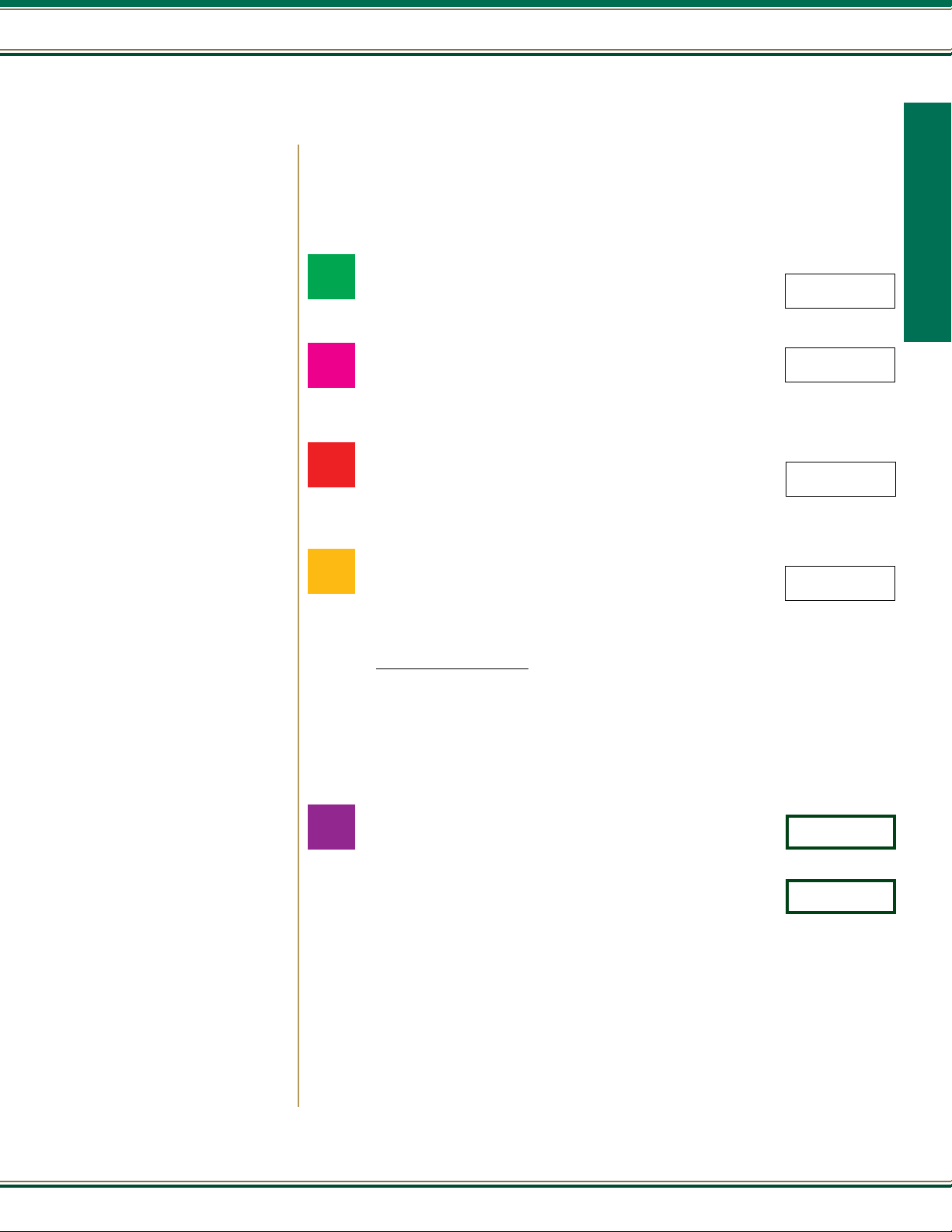
How a Centrifugal Pump Works
A centrifugal pump is a very simple design. The only moving part is an impeller attached to a shaft that is
driven by the motor. The two main parts of the pump are the impeller and diffuser. The impeller can be made
of bronze, stainless steel, cast iron, polycarbonate, and a variety of other materials. A diffuser or volute
houses the impeller and captures the water off the impeller.
Water enters the eye of the impeller and is thrown out by centrifugal force. As water leaves the eye of the
impeller, a low pressure area is created, causing more liquid to ow toward the inlet because of atmospheric
Pump Basics
pressure and centrifugal force. Velocity is developed as the liquid ows through the impeller while it is
turning at high speeds on the shaft. The liquid velocity is collected by the diffuser or volute and converted
to pressure by specially designed passageways that direct the ow to discharge into the piping system, or
on to another impeller stage for further increasing of pressure.
Diffuser
The head or pressure that a pump will develop is in direct relation to the impeller diameter, the number of
impellers, the eye or inlet opening size, and how much velocity is developed from the speed of the shaft
rotation. Capacity is determined by the exit width of the impeller. All of these factors affect the horsepower size of the motor to be used; as the more water
to be pumped or pressure to be developed, the more energy is needed.
A centrifugal pump is not positive acting. As the depth to water increases, it pumps less and less water. Also, when it pumps against increasing pressure
it pumps less water. For these reasons it is important to select a centrifugal pump that is designed to do a particular pumping job. For higher pressures
or greater lifts, two or more impellers are commonly used; or a jet ejector is added to assist the impellers in raising the pressure.
Impeller
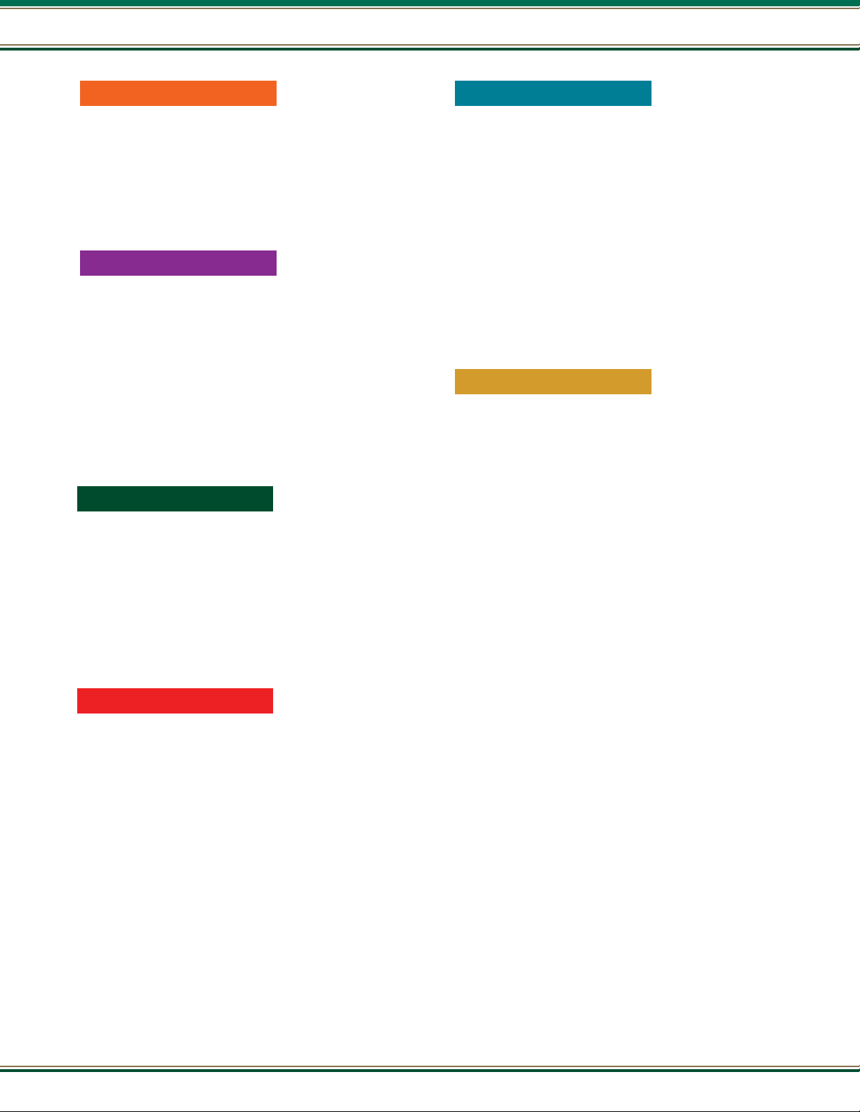
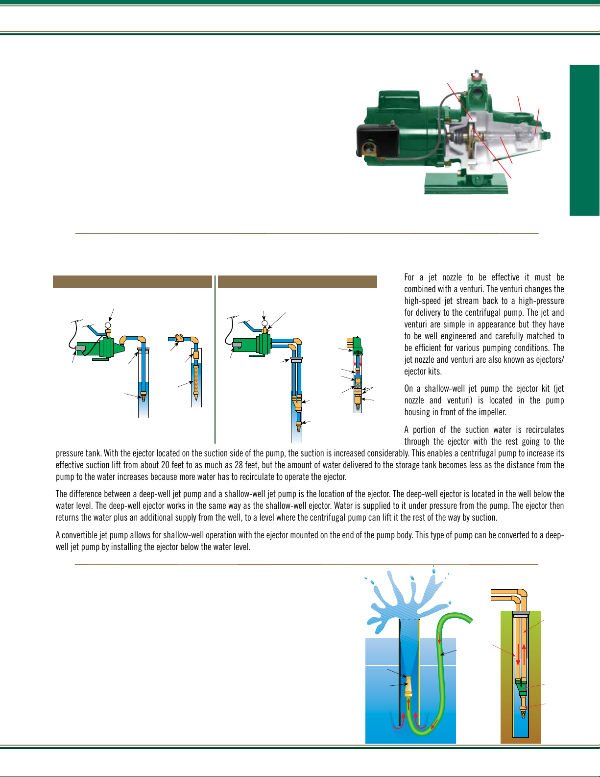
Which Pump Do I Need?
The two most popular types of pumps used for private well systems or low ow irrigation applications are jet pumps and submersible pumps.
Submersible Pump End
Jet Pump
Impeller /
Diffuser Stack
Diffuser
Suction
Nozzle
Venturi
Impeller
8
800.292.2737 | FAX 800.832.9296 | sales@aymcdonald.com | aymcdonald.com
1-19
Page 9
Pump Basics
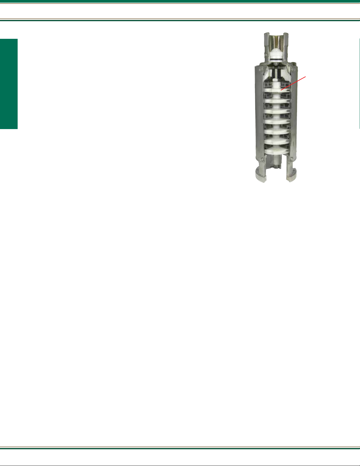
For a jet nozzle to be effective it must be
combined with a venturi. The venturi changes the
high-speed jet stream back to a high-pressure
for delivery to the centrifugal pump. The jet and
venturi are simple in appearance but they have
to be well engineered and carefully matched to
be efcient for various pumping conditions. The
jet nozzle and venturi are also known as ejectors/
ejector kits.
On a shallow-well jet pump the ejector kit (jet
nozzle and venturi) is located in the pump
housing in front of the impeller.
A portion of the suction water is recirculates
through the ejector with the rest going to the
pressure tank. With the ejector located on the suction side of the pump, the suction is increased considerably. This enables a centrifugal pump to increase its
effective suction lift from about 20 feet to as much as 28 feet, but the amount of water delivered to the storage tank becomes less as the distance from the
pump to the water increases because more water has to recirculate to operate the ejector.
The difference between a deep-well jet pump and a shallow-well jet pump is the location of the ejector. The deep-well ejector is located in the well below the
water level. The deep-well ejector works in the same way as the shallow-well ejector. Water is supplied to it under pressure from the pump. The ejector then
returns the water plus an additional supply from the well, to a level where the centrifugal pump can lift it the rest of the way by suction.
A convertible jet pump allows for shallow-well operation with the ejector mounted on the end of the pump body. This type of pump can be converted to a deep-
well jet pump by installing the ejector below the water level.
Jet
Nozzle
Water
Under
Pressure
Jet Ejector
Drive
Pipe
Return Pipe
Foot Valve
Jet Pumps
A deep well ejector is of particular value when you have a water level that is gradually
lowering. The proper jet package will be required to work efciently.
Diffuser
Suction
Nozzle
Because jet pumps are centrifugal pumps, the air handling characteristics are such
that the pump should be started with the pump and piping connections to the water
supply completely lled with water.
With a shallow-well jet pump, the ejector is mounted close to the pump impeller. With a
deep well jet pump, the ejector is usually mounted just above the water level in the well,
or else submerged below water level.
Venturi
Impeller
Centrifugal pumps, both the shallow-well and deep well types have little or no ability to pump air. When starting, the pump and suction line needs to have
all of the air removed. An air leak in the suction line will cause the pump to quit pumping. This is or sometimes referred to as “losing its prime”.
Typical Jet Pump Installation
Deep Well
TWO PIPE SYSTEM
Pressure
Regulator
Well
Seal
Jet
Ejector
Foot
Valve
SINGLE PIPE SYSTEM
Reducing
Nipple
Turned
Coupling
Packer
Ejector
Cup
Leathers
Foot Valve
To safety
switch or
circuit
breaker panel
Pressure
Switch
Shallow Well
Pressure
Gauge
Well
Seal
Foot
Valve
Check
Valve
Well
Point
Vertical
Check
Valve
To safety
switch or
circuit
breaker panel
Pressure
Switch
Pump Basics
How a Jet Provides
Pumping Action
Water is supplied to the Jet ejector under pressure. Water surrounding the jet stream is
lifted and carried up the pipe as a result of the jet action.
When a jet is used with a centrifugal pump a portion of the water delivered by the pump
is returned to the jet ejector to operate It. The jet lifts water from the well to a level where
the centrifugal pump can nish lifting It by suction.
9
Page 10
Pump Basics
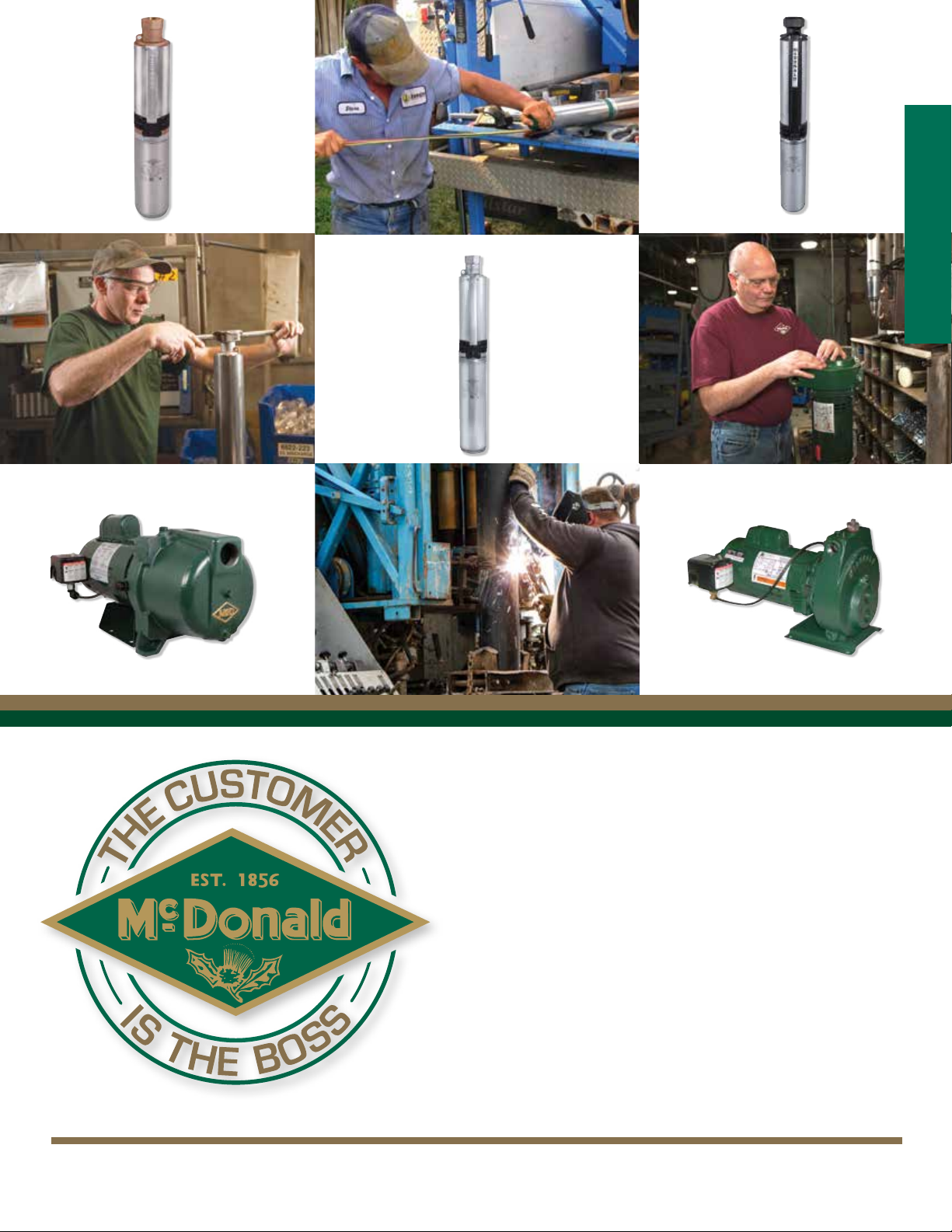
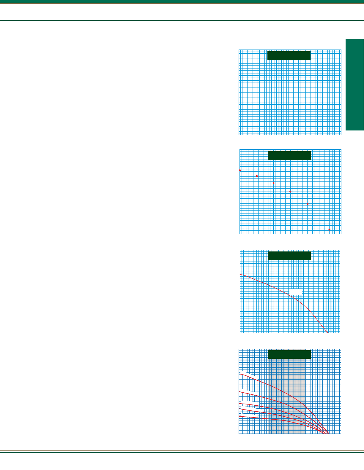
Submersible Pumps
The submersible pump is a centrifugal pump. Because all stages of the pump end (wet end) and the motor are
joined and submerged in the water, it has a great advantage over other centrifugal pumps. There is no need to
recirculate or generate drive water as there is with jet pumps, therefore, most of its energy goes toward “pushing”
the water rather than ghting gravity and atmospheric pressure to draw water.
Virtually all submersibles are “multi-stage” pumps. All of the impellers of the multi-stage submersible pump are
Pump Basics
mounted on a single shaft and all rotate at the same speed. Each impeller passes the water to the eye of the next
impeller through a diffuser. The diffuser is shaped to slow down the ow of water and convert velocity to pressure.
Each impeller and matching diffuser is called a stage. As many stages are used as necessary to push the water
out of the well at the required system pressure and capacity. Each time water is pumped from one impeller to the
next, its pressure is increased.
The pump and motor assembly are lowered into the well by connecting piping to a position below the water level. In
this way the pump is always lled with water (primed) and ready to pump. Because the motor and pump are under
water they operate more quietly than above ground installations and pump freezing is not a concern.
A.Y. McDonald can stack as many impellers as needed; however, the horsepower of the motor is limited. For instance,
numerous pumps have 1/2 HP ratings - pumps that are capable of pumping different ows at different pumping
levels; they will, however, always be limited to 1/2 HP. Another way to look at it is that a pump will always operate somewhere along its design curve.
Impeller /
Diffuser Stack
To get more ow, the exit width of the impeller is increased and there will then be less pressure (or head) that the pump will develop because there will be
less impellers on a given HP size pump. Remember, the pump will always trade-off one for the other depending on the demand of the system. If the system
demands more than a particular pump can produce, it will be necessary to go up in horsepower; thereby, allowing more impellers to be stacked or to go to a
different design pump with wider impellers.
10
800.292.2737 | FAX 800.832.9296 | sales@aymcdonald.com | aymcdonald.com
1-19
Page 11
Pump Curves
1000
900
800
700
600
500
400
300
200
100
CAPACITY IN U.S. GALLONS PER MINUTE
TOTAL DYNAMIC HEAD IN FEET
0 4 8 12 16 20 24 28 32 36 40 44 48
1000
900
800
700
600
500
400
300
200
100
CAPACITY IN U.S. GALLONS PER MINUTE
TOTAL DYNAMIC HEAD IN FEET
0 4 8 12 16 20 24 28 32 36 40 44 48
H - C
1000
900
800
700
600
500
400
300
200
100
CAPACITY IN U.S. GALLONS PER MINUTE
TOTAL DYNAMIC HEAD IN FEET
0 4 8 12 16 20 24 28 32 36 40 44 48
1000
900
800
700
600
500
400
300
200
100
5
H
P
-
2
8
S
t
a
g
e
s
3
H
P
-
1
9
S
t
a
g
e
s
2
H
P
-
1
4
S
t
a
g
e
s
1
1
/
2
H
P
-
1
1
S
t
a
g
e
s
1
H
P
-
8
S
t
a
g
e
s
CAPACITY IN U.S. GALLONS PER MINUTE
TOTAL DYNAMIC HEAD IN FEET
0 4 8 12 16 20 24 28 32 36 40 44 48
Pump Basics
A pump curve is a curved line drawn over a grid of vertical and horizontal lines. The curved line
represents the performance of a given pump. The vertical and horizontal grid lines represent units
of measure to display that performance.
Let’s think of a well full of water. We want to use the water in a home. The home is at a higher level
than the water in the well. Since gravity won’t allow water to ow uphill, we use a pump. A pump
is a machine used to move a volume of water a given distance. This volume is measured over a
period of time expressed in gallons per minute (GPM) or gallons per hour (GPH).
The pump develops energy called discharge pressure or total dynamic head. This discharge
pressure is expressed in units of measure called pounds per square inch (psi) or feet of head (ft).
NOTE: 1 psi will push a column of water up a pipe a distance of 2.31 feet. When measuring
a pump’s performance, we can use a curve to determine which pump is best to meet our
requirements.
Figure 1 is a grid with the unit of measure in feet on the left hand side. We start with 0 at the
bottom. The numbers printed as you go up the vertical axis relate to the ability of the pump to
produce pressure expressed in feet. Always determine the value of each grid line. Sometimes the
measure will say feet head, which is what most engineers call it.
With the pump running a reading was taken from the gauge in psi and converted to feet
(1 psi = 2.31 feet).
We show another unit of measure in gallons per minute across the bottom. You start with 0 on
the left. The numbers printed as you go to the right relate to the ability of the pump to produce
ow of water expressed as capacity—in gallons per minute (GPM). Again, always determine the
value of each grid line.
FIGURE 1
Pump Basics
FIGURE 2
To establish a pump curve we run the pump using a gauge, valve, and owmeter on the discharge
pipe. We rst run the pump with the valve closed and read the gauge. This gives us the pump’s
capability at 0 capacity and maximum head in feet.
Figure 2 - We mark the grid point 1. Next we open the valve to 8 GPM ow, and read the gauge.
We again mark this point on the grid 2. We continue this process until we have
marked all the points on the grid.
Figure 3 - We now connect all the points. This curved line is called a head/capacity curve.
Head (H) is expressed in feet and capacity (C) is expressed in gallons per minute (GPM).
The pump will always run somewhere on the curve.
When the total dynamic head (TDH) is known, read vertically up the left hand side of the curve to
that requirement, for example, 300 feet. Then read horizontally to a point on a curve that connects
to the capacity needed, for example 26 GPM. It is then determined that a 3 HP 19 stage pump is
needed.
There are many different type curves shown in our catalog. Figure 4 is a composite performance
curve (more than one pump) for the submersible. There is a separate curve for each horsepower
size. Let’s compare two sizes:
1. First look at the 1 HP, 8 stages (impellers and diffusers). At 20 GPM capacity this model will
make 160 feet.
2. Now look at the 5 HP, 28 stages. At 20 GPM capacity this model will make 500 feet.
When you add impellers, the pump makes more pressure (expressed in feet). This allows the pump
to go deeper in a well, but also takes more horsepower.
FIGURE 3
FIGURE 4
11
Page 12
Pump Basics
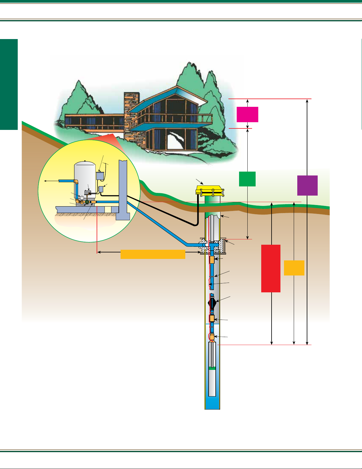
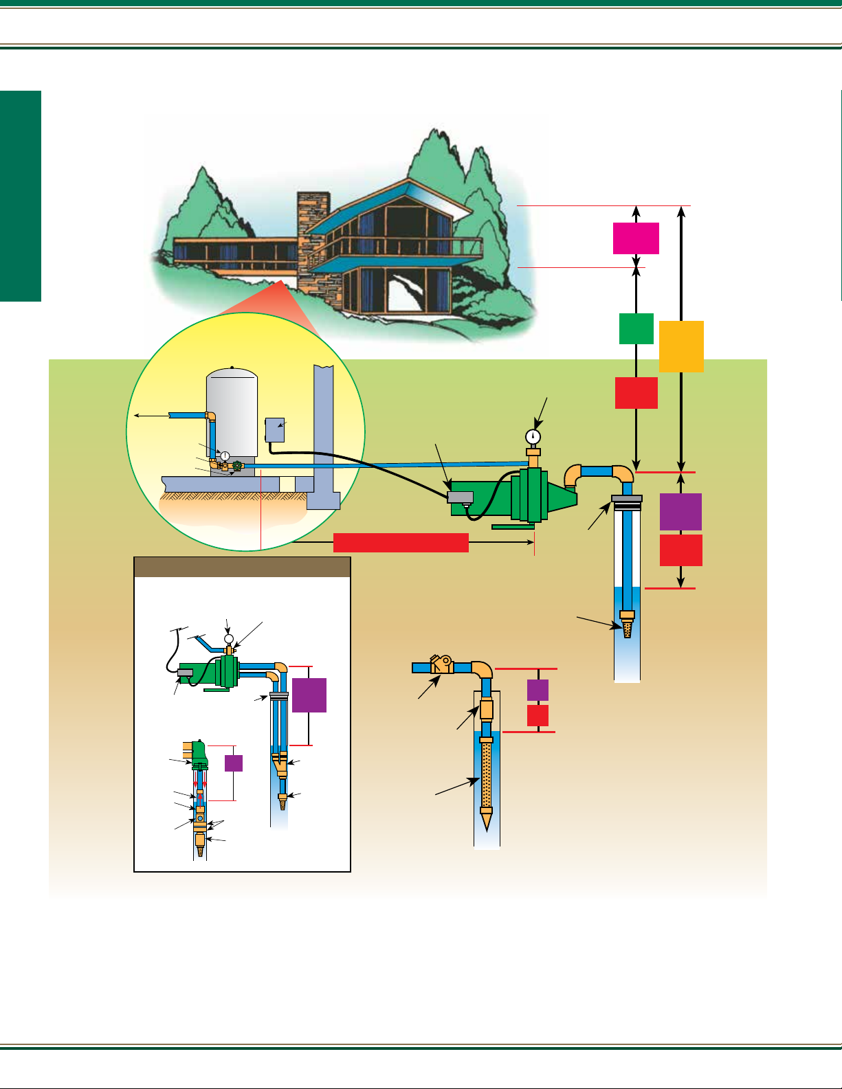
Typical Submersible Installation
Pump Basics
Disconnect
Switch/Circuit
Breaker
PRESSURE
TANK
TO HOUSE SERVICE
Pressure Relief Valve
Drain Valve
Pressure
Gauge
Pressure
Switch
Control
Box
Well Cap
2
Service
Pressure
1
Vertical
Lift
5
Total
Dynamic
Head
Check Valve
(Where local codes allow)
Horizontal & Vertical PIpe Run
All Pipe from pump to tank
Well
Casing
Pitless
Adapter
Check Valve
Tape Cable
to Pipe
Submersible
Cable
Torque Arrester
Coupling
Check Valve
3
Pumping
Level
Consists of:
Static or
Standing
Water
Level
Draw
Down
4
Friction
Loss
12
800.292.2737 | FAX 800.832.9296 | sales@aymcdonald.com | aymcdonald.com
1-19
Page 13
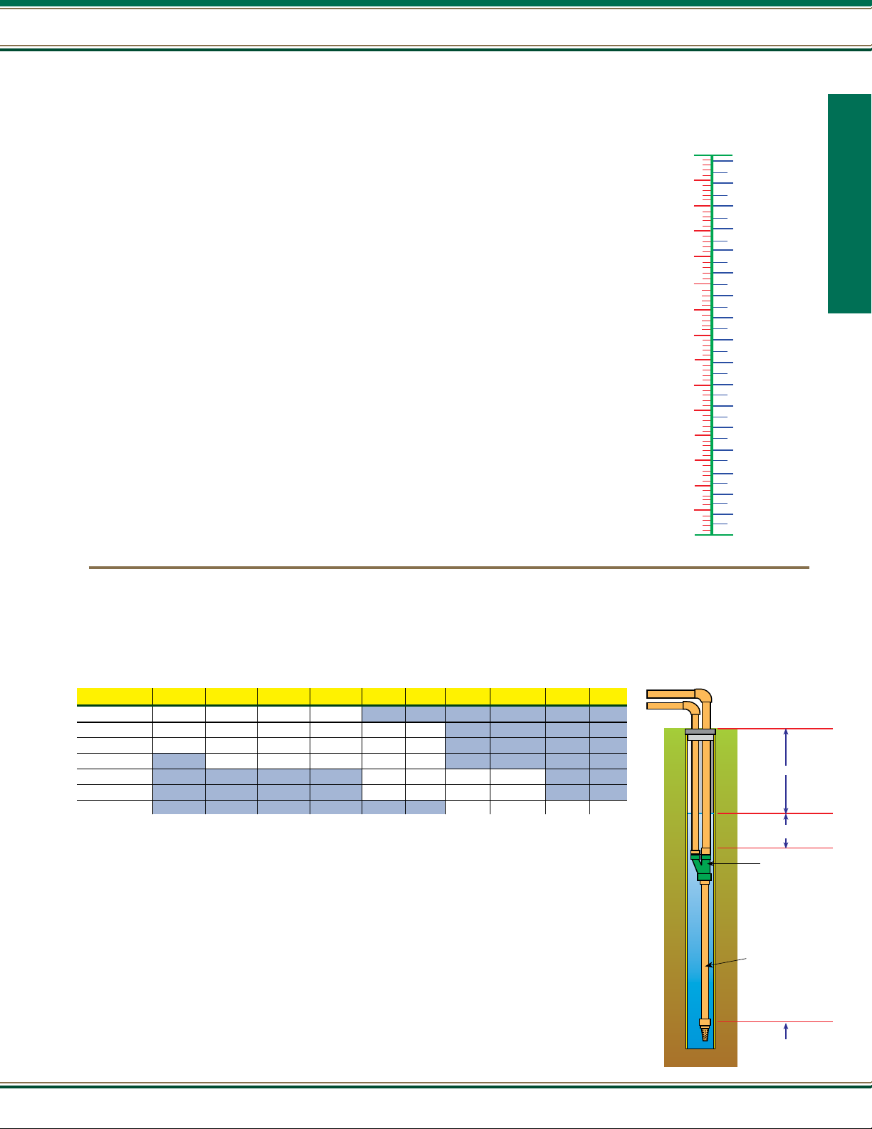
Pump Sizing - Submersible Pumps
MORE ABOUT...
VERTICAL LIFT/ ELEVATION
The vertical distance between the well
head and the level at the point of use.
It must be added to the TOTAL DYNAMIC
HEAD if the inlet is lower than the outlet and subtracted if the inlet is higher.
As a rule of good installation practice,
however, pipes should slope continuously
upward from the inlet to the outlet to prevent entrapment of air.
SERVICE PRESSURE
The range of pressure in the pressure
tank during the pumping cycle.
Determining Total Dynamic Head
Vertical Lift / Elevation
The vertical distance in feet from the pitless adapter to the top of
1
the pressure tank
Service Pressure
The average (pump shut-off) pressure switch setting x 2.31'.
2
Example for a 30/50 switch: 40 x 2.31' = 92.4 feet
Pump Basics
Well Size
(inside diameter in inches)
__________
HEAD
+
Convert PSI to feet
(X 2.31)
Pump Basics
PUMPING LEVEL
The lowest water level reached during
pumping operation. (Static level – drawdown)
STATIC OR STANDING WATER LEVEL
The undisturbed level of water in the well
before pumping. Not as important as
pumping level.
DRAWDOWN
The distance that the water level in the
well is lowered by pumping. It is the difference between the STATIC WATER LEVEL
and the PUMPING LEVEL.
FRICTION LOSS
The loss of pressure or head due to the
resistance to ow in the pipe and ttings. Friction loss is inuenced by pipe
size and uid velocity, and is usually ex-
pressed in feet of head.
HORIZONTAL RUN
The horizontal distance between the
point where uid enters a pipe and the
point at which it leaves.
TOTAL DYNAMIC HEAD or TDH
TDH and capacity required determines
pump size. The total pressure or head
the pump must develop is the sum of the
VERTICAL LIFT/ELEVATION, THE SERVICE
PRESSURE, PUMPING LEVEL, and THE
FRICTION LOSS. All of these measurements must be expressed in the same
units, usually feet of head or pressure
(PSI), before adding them together.
Pumping Level
The vertical distance in feet from the pitless adapter or well seal
3
to the water drawdown level in the well that yields the ow rate
required by the pump
+
+
Friction Loss
Water owing through piping will lose head depending on the size,
4
type and length of piping, number of ttings, and ow rate. Example:
Pumping 20 GPM through 500 ft. of 1 1/4" plastic pipe with three
elbows will cause a friction loss equal to:
500 ft. + 21 ft. (elbow loss)
100 ft.
Feet of Pipe _______________ Diameter of Pipe ______________
Type of Pipe __________________________________________
See Friction Loss Charts on Page 16
Total Dynamic Head
5
After determining TDH, match this number with capacity required
on pump curves of specic pumps in this catalog to select the
correct pump.
Gallons Per Minute (or Hour) Needed
Determining Flow Rate
Although methods will vary, in general, the Water Systems Council bases pump ow selection for a residential
system on total gallon usage during a seven minute peak demand period. This can be supplemented by using
a properly sized pressure tank.
Farms, irrigation, and lawn sprinklers demand more water.
X 6.00 ft (loss per 100') = 31.26 ft.
=
Ft.
13
Page 14
Pump Basics
Typical Jet Pump Installation
SHALLOW WATER
Pump Basics
TO HOUSE SERVICE
Pressure Relief Valve
Drain Valve
To safety
switch or
circuit breaker
panel
Pressure
Gauge
PRESSURE
TANK
Deep Well
TWO PIPE SYSTEM
Pressure
Gauge
Pressure
Regulator
Safety
Switch
Circuit
Breaker
Pressure Switch
Horizontal & Vertical Pipe Run
All pipe from pump to tank
Pressure Gauge
Foot
Valve
Well
Seal
2
Service
Pressure
1
Vertical
Lift
3
Friction
Loss
4
Total
Discharge
Head
(Pressure)
5
Pumping
Level
3
Friction
Loss
14
Pressure
Switch
SINGLE PIPE SYSTEM
Casing
Adapter
Reducing
Nipple
Turned
Coupling
Packer
Ejector
Well
Seal
5
Cup Leathers
Foot Valve
5
Pumping
Level
Jet Ejector
Foot Valve
Horizontal
Check Valve
Well Point
(if used)
Vertical
Check Valve
5
3
800.292.2737 | FAX 800.832.9296 | sales@aymcdonald.com | aymcdonald.com
1-19
Page 15
Pump Basics
Aboveground Pumps
The difference between submersible pump and surface pump sizing is that surface pumps, including jet pumps, show performance in “charted” form
versus “curves” for submersibles. Except for the “pumping level” (which is shown in feet in the charts) all other head/lift requirements should be
converted to PSIG for surface pump sizing. (Feet X .433 = PSIG (Pounds per Square Inch Gauge).
MORE ABOUT...
VERTICAL LIFT/ ELEVATION
The vertical distance between the
well head and the level at the point
of use. It must be ADDED to the
Total Dynamic/Total Discharge Head
if the inlet is lower than the outlet
and SUBTRACTED if the inlet is
higher. As a rule of good installation
practice, however, pipes should slope
continuously upward from the inlet to
the outlet to prevent entrapment of
air.
SERVICE PRESSURE
The range of pressure in the pressure tank
during the pumping cycle.
FRICTION LOSS
The loss of pressure or head due to
the resistance to ow in the pipe and
ttings. Friction loss is inuenced
by pipe size and uid velocity, and is
usually expressed in feet of head.
HORIZONTAL RUN
The horizontal distance between the
point where uid enters a pipe and the
point at which it leaves.
Vertical Lift / Elevation
1
The vertical distance in feet from the location of the pump
to the point of highest delivery (e.g. from a pump house
near the well to the second oor of a two story house)
Service Pressure
The average pressure switch setting.
2
Example 20/40 switch (1/2 HP) = 30 PSIG average (3/4 HP and larger pumps
have 30/50 switch settings) = 40 PSIG average
Friction Loss
3
Water owing through piping will lose head depending on the
size, type and length of piping, number of ttings, and ow
rate. Example: Pumping 10 GPM through 100 ft. of 1" plastic
pipe with 3 elbows will cause a friction loss equal to:
100 ft. + 18 ft. (elbow loss)
100 ft.
Feet of Pipe ___________ Diameter of Pipe __________
Type of Pipe __________________________________
See Friction Loss Charts on Page 16
X 6.31 ft (loss per 100') = 7.44' X .433 = 3.2 PSIG
X .433
X .433
Well Size
(inside diameter
in inches)
_________
PSIGFeet
+
PSIG
+
PSIGFeet
=
Pump Basics
TOTAL DYNAMIC/TOTAL
DISCHARGE HEAD or TDH
TDH and capacity required
determines pump size. The total
pressure or head the pump must
develop is the sum of Vertical Lift/
Elevation, The Service Pressure,
and The Friction Loss. All of these
measurements must be expressed in
the same units, usually feet of head
or pressure (PSI), before adding them
together. For aboveground pumps,
distance to water in feet are shown in
the respective charts.
PUMPING LEVEL
The lowest water level reached during
pumping operation. (Static level minus
drawdown)
STATIC OR STANDING WATER LEVEL
The undisturbed level of water in the
well before pumping. Not as important
as pumping level.
DRAWDOWN
The distance that the water level in the
well is lowered by pumping. It is the
difference between the STATIC WATER
LEVEL and the PUMPING LEVEL.
Total Dynamic/Discharge Head • 1 + 2 + 3 =
4
Pumping Level/Depth to Water
5
The vertical distance in feet from the pump to the water level including
draw down level - if any. In Shallow Well systems, referred to as suction
lift/head and is limited to 20 or 25 feet at sea level (deduct 1’ suction
capability for each 1000’ above sea level).
Note: Friction losses (3) in the suction piping must be added to the
pumping level for total suction lift.
Deep Well jet pump charts include the friction losses in the vertical piping
only. See page 15 if long horizontal, offset piping cannot be avoided.
No need to
convert-
Charts are
in feet
If 25' or less,
use shallow
well charts
If more than 25'
use deep
well charts
Determining Flow Rate
Although methods will vary, in general, the Water Systems Council bases pump ow selection for a
residential system on total gallon usage during a seven minute peak demand period. This can be
supplemented by using a properly sized pressure tank.
Farms, irrigation, and lawn sprinklers demand more water.
Gallons Per Minute (or hour) Needed
See Page 20 for water demands
After determining TDH and ow requirements in GPM / GPH, match these numbers
with surface pump charts in sections 3 and 4.
PSIG
Ft.
15
Page 16
Pump Basics
Friction Loss - Charts
LOSS OF HEAD IN FEET, DUE TO FRICTION PER 100 FEET OF PIPE
3/4” Pipe
FLOW STEEL PLASTIC
US GAL C-100 C-140
MIN ID .824” ID .824”
1.5 1.13 .61
Pump Basics
2.0 1.93 1.04
2.5 2.91 1.57
3.0 4.08 2.21
3.5 5.42 2.93
4.0 6.94 3.74
4.5 8.63 4.66
5.0 10.50 5.66
6.0 -- 7.95
7.0 -- 10.60
2” Pipe 2 1/2” Pipe
FLOW STEEL PLASTIC
US GAL C-100 C-140
MIN ID 2.067” ID 2.067”
10 .431 .233
15 .916 .495
20 1.55 .839
25 2.35 1.27
30 3.29 1.78
35 4.37 2.36
40 5.60 3.03
45 6.96 3.76
50 8.46 4.57
55 10.10 5.46
60 11.90 6.44
70 -- 8.53
80 -- 10.90
1” Pipe
FLOW STEEL PLASTIC
US GAL C-100 C-140
MIN ID 1.049” ID 1.049”
2 .595 .322
3 1.26 .680
4 2.14 1.15
5 3.42 1.75
6 4.54 2.45
8 7.73 4.16
10 11.7 6.31
12 -- 8.85
14 -- 11.8
FLOW STEEL PLASTIC
US GAL C-100 C-140
MIN ID 2.469” ID 2.469”
20 .654 .353
30 1.39 .750
40 2.36 1.27
50 3.56 1.92
60 4.99 2.69
70 6.64 3.58
80 8.50 4.59
90 10.60 5.72
100 -- 6.90
110 -- 8.25
120 -- 9.71
130 -- 11.30
1 1/4” Pipe
FLOW STEEL PLASTIC
US GAL C-100 C-140
MIN ID 1.380” ID 1.380”
4 .564 .304
5 .853 .460
6 1.20 .649
7 1.59 .860
8 2.04 1.10
10 3.08 1.67
12 4.31 2.33
14 5.73 3.10
16 7.34 3.96
18 9.13 4.93
20 11.10 6.00
25 -- 9.06
1 1/2” Pipe
FLOW STEEL PLASTIC
US GAL C-100 C-140
MIN ID 1.61” ID 1.61”
4 .267 .144
6 .565 .305
8 .962 .520
10 1.45 .785
12 2.04 1.10
14 2.71 1.46
16 3.47 1.87
18 4.31 2.33
20 5.24 2.83
25 7.90 4.26
30 11.1 6.0
35 -- 7.94
40 -- 10.20
3” Pipe 4” Pipe
FLOW STEEL PLASTIC
US GAL C-100 C-140
MIN ID 3.0” ID 3.068”
20 .149 .129
30 .316 .267
40 .541 .449
50 .825 .676
60 1.17 .912
70 1.57 1.22
80 2.03 1.56
90 2.55 1.95
100 3.12 2.37
110 3.75 2.84
120 4.45 3.35
130 5.19 3.90
140 6.00 4.50
FLOW STEEL PLASTIC
US GAL C-100 C-140
MIN ID 4.0” ID 4.026”
20 .038 .035
30 .076 .072
40 .128 .120
50 .194 .179
60 .273 .250
70 .365 .330
80 .470 .422
90 .588 .523
100 .719 .613
110 .862 .732
120 1.02 .861
130 1.19 1.00
140 1.37 1.15
16
Example:
10 GPM with 1’ plastic pipe has 6.31’ of loss per 100 ft. - if your run is 50 ft., multiply by .5, if 250 ft. multiply by 2.5, etc.
Loss through ttings in terms of equivalent lengths of pipe
PIPE & FTG.
TYPE FITTING MATERIAL.
& APPLICATION (Note 1)
1/2 3/4 1 1
Insert coupling Plastic 3 3 3 3 3 3 3
Threaded adapter
Plastic or copper Copper 1 1 1 1 1 1 1
to thread Plastic 3 3 3 3 3 3 3
Steel 2 3 3 4 4 5 6
90° standard elbow Copper 2 3 3 4 4 5 6
Plastic 4 5 6 7 8 9 10
Note 1: Loss gures are based on equivalent lengths of indicated pipe material
Note 2: Loss gures are for screwed valves and are based on equivalent lengths of steel pipe
Note 3: Loss gures for copper lines are approximately 10% higher than shown for plastic
800.292.2737 | FAX 800.832.9296 | sales@aymcdonald.com | aymcdonald.com
EQUIVALENT LENGTH OF PIPE
NOMINAL SIZE FITTING & PIPE
1
⁄4 11⁄2 2 21⁄
PIPE & FTG.
TYPE FITTING MATERIAL.
& APPLICATION (Note 1)
1/2 3/4 1 1
2
Steel 4 5 6 8 9 11 14
Standard tee Copper 4 5 6 8 9 11 14
Flow through side Plastic 7 8 9 12 13 17 20
Gate valve Note 2 2 3 4 5 6 7 8
Swing check valve Note 2 4 5 7 9 11 13 16
EQUIVALENT LENGTH OF PIPE
NOMINAL SIZE FITTING & PIPE
1
⁄4 11⁄2 2 21⁄
2
1-19
Page 17
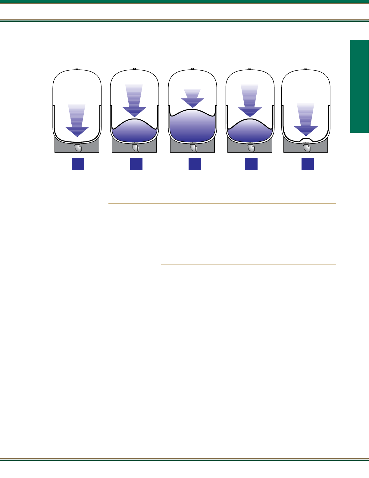
Pressure Tank - Sizing
Precharge Air
Pressure
Air Pressure
Increasing
Pressure
Switch Cut-Out
Pressure
Air Pressure
Decreasing
Pressure
Switch Cut-In
Pressure
Tank empty
Pump comes
on and cycle
begins
1
Tank is filling
2
Tank is full
Pump turns off
3
Water is
being used
4
Tank is nearly
empty and pump
comes on to
repeat cycle
5
TANK OPERATIONS
Pump Basics
Pump Basics
Why do I need a tank?
There are four main reasons to include a tank in your system:
1. To protect and extend the life of the pump by reducing the number of cycles.
2. To provide storage of water under pressure for delivery between cycles.
3. To have reserve capacity for periods of peak demand.
4. To reduce system maintenance.
How do I choose a tank for my system?
Choosing the proper tank for your pumping system will greatly reduce the risk of premature pump failure. Most manufacturers recommend a
minimum run time of one minute in order to protect the pump and the pump motor. The larger the tank the longer the running time and fewer
pump cycles will result in longer pump life. One HP and larger pumps require longer run times.
To determine the proper size of tank, there are three factors to consider:
1. Pump ow rate in gallons per minute
2. Desired run time of the pump
3. Cut-in and cut-out psi of the pressure switch
From these factors you can determine the tank drawdown with the following equation:
Pump ow rate X run time = tank drawdown capacity required.
Tank drawdown capacity is the minimum amount of water stored and/or delivered by the pressure tank between pump shut-off and pump re-start.
This should not be confused with “tank volume.” For example, a pre-charged tank with a tank volume of 20 gallons has only ve to seven gallons
drawdown capacity depending on the cut-in / cut-out (on/off) setting of the pressure switch.
Pumps with ow rates (capacities) up to 10 GPM should have a tank with a minimum of one gallon drawdown capacity for each GPM delivered by
the pump. Example: 10 GPM pump = 10 gallon “drawdown”.
Pump ow rates from 11 to 20 GPM should have tank drawdowns approximately 1.5 times the GPM rating.
For example, 20 GPM X 1.5 = 30 gallon “drawdown”.
Pump ow rates above 20 GPM should have tank drawdowns approximately two times the GPM rating and multiple tanks should be considered.
(CHECK YOUR TANK MANUFACTURER’S CHARTS FOR TANK DRAWDOWN RATING.)
17
Page 18

Pump Basics
Technical Data - Glossary
ACIDITY - A condition of water when the pH is below 7. See pH.
ALKALINITY - A condition of water when the pH is above 7. See pH.
AQUIFER - A water-saturated geologic unit or system that yields water to wells or springs at a sufcient rate that the wells or springs can serve as practical sources
of water.
Pump Basics
ARTESIAN WELL (owing and non-owing) - Well in which the water rises above the surface of the water in the aquifer after drilling is completed. It is a owing
artesian well if the water rises above the surface of the earth.
CENTRIFUGAL - Consists of a fan-shaped impeller rotating in a circular housing, pushing liquid towards a discharge opening. Simple design, only wearing parts are
the shaft seal and bearings (if so equipped). Usually used where a ow of liquid at relatively low pressure is desired. Not self-priming unless provided with a priming
reservoir or foot valve: works best with the liquid source higher than the pump (ooded suction/gravity feed). As the discharge pressure (head) increases, ow and driven
power requirements decrease. Maximum ow and motor loading occur at minimum head.
CHECK VALVE - Allows liquid to ow in one direction only. Generally used in suction and discharge line to prevent reverse ow.
CISTERN - A non-pressurized tank (usually underground) for storing water.
COAGULATION - The chemically combining of small particles suspended in water.
CONTAMINATED WATER - Water that contains a disease causing or toxic substances.
DEEP WELL - Use a pump (submersible or deep well jet) to force water upward from a pumping element below the well water level. Not restricted by suction lift
limitations.
DRAWDOWN - The vertical distance the water level drops in a well pumped at a given rate.
DYNAMIC HEAD - Vertical distances (in feet) when the pump is running/producing water.
FLOODED SUCTION - Liquid source is higher than pump and liquid ows to pump by gravity (Preferable for centrifugal pump installations).
FLOW - The measure of the liquid volume capacity of a pump. Given in Gallons Per Hour (GPH) or Gallons Per Minute (GPM), as well as Cubic Meters Per Hour (CMPH),
and Liters Per Minute (LPM).
FOOT VALVE - A type of check valve with a built-in strainer. Used at point of liquid intake to retain liquid in the system, preventing loss of prime when liquid source
is lower than pump.
FRICTION LOSS - The loss of pressure or head due to the resistance to ow in the pipe and ttings. Friction loss is inuenced by pipe size and uid velocity, and is
usually expressed in feet of head.
GRAINS PER GALLON - The weight of a substance, in grains, in a gallon. Commonly, grains of minerals per gallon of water as a measure of water hardness.
1 gpg = 17.1 mgl.
GROUND WATER - Water that has ltered down to a saturated geologic formation beneath the earth’s surface.
HARDNESS MINERALS - Minerals dissolved in water that increase the scaling properties and decrease cleansing action - usually calcium, iron, and magnesium.
HEAD - Another measure of pressure, expressed in feet. Indicates the height of a column of water being lifted by the pump neglecting friction losses in piping.
INCRUSTATION - A mineral scale chemically or physically deposited on wetted surfaces, such as well screens, gravel packs, and in tea kettles.
INTERMEDIATE STORAGE - A holding tank included in a water system when the water source does not supply the peak use rate.
JET PUMP - A pump combining two pumping principles - centrifugal operation and ejection. Can be used in shallow or deep wells.
MILLIGRAMS PER LITER (mg/l) - The weight of a substance, in milligrams in a liter. 1 mg/l = 1 oz. per 7500 gallons. It is equivalent to 1 ppm.
See Parts per Million.
NEUTRALITY - A condition of water when the pH is at 7. See pH.
18
800.292.2737 | FAX 800.832.9296 | sales@aymcdonald.com | aymcdonald.com
1-19
Page 19

Technical Data - Glossary
Pump Basics
OXIDATION - A chemical reaction between a substance and oxygen.
PALATABLE WATER - Water of acceptable taste. May also include non-offensive appearance and odor.
PARTS PER MILLION, ppm - A measure of concentration; one unit of weight or volume of one material dispersed in one million units of another; e.g., chlorine
in water, carbon monoxide in air. Equivalents to indicate small size of this unit: 1 ppm = 1 oz. per 7500 gallons; 1 kernel of corn in 13 bushels 1/4 sq. in. in an acre.
PEAK USE RATE - The ow rate necessary to meet the expected maximum water demand in the system.
pH - A measure of the acidity or alkalinity of water. Below 7 is acid, above 7 is alkaline.
POLLUTED WATER - Water containing a natural or man-made impurity.
POTABLE WATER - Water safe for drinking.
PRESSURE - The force exerted on the walls of a container (tank pipe, etc.) by the liquid. Measured in pounds per square inch (PSI).
PRIME - A charge of liquid required to begin pumping action of centrifugal pumps when liquid source is lower than pump. May be held in pump by a foot valve on the
intake line or a valve or chamber within the pump.
RELIEF VALVE - Usually used at the discharge of a pump. An adjustable, spring-loaded valve opens, or relieves pressure when a pre-set pressure is reached. Used
to prevent excessive pressure and pump or motor damage if discharge line is closed off.
SHALLOW WELL - Use a pump located above ground to lift water out of the ground through a suction pipe. Limit is a lift of 33.9 feet at sea level.
SOFTENING - The process of removing hardness caused by calcium and magnesium minerals.
SPRING - A place on the earth’s surface where ground water emerges naturally.
STATIC HEAD - Vertical Distance (in feet) from pump to point of discharge when the pump is not running.
Pump Basics
STRAINERS - A device installed in the inlet of a pump to prevent foreign particles from damaging the internal parts.
SUBMERGENCE / SETTING - The vertical distance between PUMPING LEVEL and the bottom of the pump or jet assembly. Submergence must be sufcient to insure
that the suction opening of the pump or jet assembly is always covered with water, while maintaining enough clearance from the bottom of the well to keep it out of
sediment (at least 10 foot clearance is recommended). Could be useful when guring friction loss.
SUBMERSIBLE - A pump which is designed to operate totally submersed in the uid which is being pumped. With water-proof electrical connections, using a motor
which is cooled by the liquid.
SUMP - A well or pit in which liquids collect below oor level.
SURGING - Forcing water back and forth rapidly and with more than normal force in a well or other part of the water system.
TOTAL HEAD - The sum of discharge head suction lift and friction losses.
VISCOSITY - The thickness of a liquid, or its ability to ow. Temperature must be stated when specifying viscosity, since most liquids ow more easily as they get
warmer. The more viscous the liquid the slower the pump speed required.
WATER TABLE WELL - A well where the water level is at the surface of the aquifer.
WATER TREATMENT - A process to improve the quality of water.
WATER WELL - A man-made hole in the earth from which ground water is removed.
WELL DEVELOPMENT - A process to increase or maintain the yield of a well.
19
Page 20

Pump Basics
Technical Data
MEASUREMENT CONVERSION FACTORS (APPROXIMATE)
Metric x Conversion Factor = Customary Customary x Conversion Factor = Metric
LENGTH
mm millimeter ............................. 0.04 inches in
cm centimeters ............................. 0.4 inches in
m meters ..................................... 3.3 feet ft
Pump Basics
m meters ..................................... 1.1 yards yd
km kilometers ............................... 0.6 miles mi
AREA
2
square centimeters ............... 0.16 square inches in
cm
m2 square meters ......................... 1.2 square yards yd
km2 square kilometers ................... 0.4 square miles mi
ha hectares (10.000 m2) ............. 2.5 acres
LENGTH
in inches ................................... 2.54 centimeters cm
ft feet ....................................... 30.5 centimeters cm
yd yards ....................................... 0.9 meters m
mi miles ....................................... 1.6 kilometers km
AREA
2
square inches ......................... 6.5 square centimeters cm
in
2
ft2 square feet ............................ 0.09 square meters m
2
yd2 square yards ........................... 0.8 square meters m
2
mi2 square miles ........................... 2.6 square kilometers km
a acres ....................................... 0.4 hectares ha
2
2
2
2
MASS (weight)
g grams ................................. 0.035 ounces oz
kg kilograms ................................ 2.2 pounds Ib
t tonnes(1000kg) ....................... 1.1 shorttons
VOLUME
ml milliliters .............................. 0.03 uid ounces n oz
l liters ....................................... 2.1 pints pt
l liters ..................................... 1.06 quarts qt
l liters ..................................... 0.26 gallons gal
3
cubic meters ......................... 35.3 cubicfeet tt
m
m3 cubic meters ........................... 1.3 cubic yards yd
m3 cubic meters ....................... 264.2 gallons gal.
FORCE/AREA
kPa kilo paschals ....................... .145 pound force/in
bar bar ........................................ 14.5 pound force/in
Average water requirements for general service
around the home and farm
Each person, per day for all purposes ............................................100 gal.
Each horse, dry cow or beef animal ..................................................12 gal.
Each milking cow .............................................................................35 gal.
Each hog per day................................................................................4 gal.
Each sheep per day ............................................................................2 gal.
For 100 chickens per day....................................................................4 gal.
2
psi
2
psi
MASS (weight)
oz ounces ..................................... 28 grams 9
Ib pounds .................................. 0.45 kilograms kg
short tons (2000 Ib) ................ 0.9 tonnes t
VOLUME
tsp teaspoons .................................. 5 milliliters ml
tbsp tablespoons ............................. 15 milliliters ml
oz uid ounces .............................30 milliliters ml
c cups ...................................... 0.24 liters
3
pt pints ..................................... 0.47 liters
3
qt quarts ................................... 0.95 liters
gal gallons .................................... 3.8 liters
3
cubic feet .............................. 0.03 cubic meters m
ft
yd3 cubic yards ........................... 0.76 cubic meters m
gal gallons .................................
FORCE/AREA
psi pound force/in
psi pound force/in
To sprinkle 1/4" of water on each
1000 sq. ft. of lawn ............................................................... 160 gal.
Dishwasher .................................................................10-20 gal. @ 2 GPM
Washer .................................................................up to 50 gal. @ 4-6 GPM
Regeneration of water softener .............................................up to 150 gal.
Average ow rate requirements by various xtures
GPM = GaI. per minute • GPH = Gal. per hour
2
...................... 6.89 kilo paschals kPa
2
...................... .069 bar bar
.0038
cubic meters m
3
3
3
20
Average amount of water required by various
home and yard xtures
Drinking fountain .............................................................. 50-100 gal./day
Each shower ................................................................25-60 gal. @ 5 GPM
To ll bathtub ...................................................................................35 gal.
To ush toilet..................................................................................3-7 gal.
To ll lavatory ................................................................................. 1-2 gal.
800.292.2737 | FAX 800.832.9296 | sales@aymcdonald.com | aymcdonald.com
Shower .......................................................................................... 3-5 GPM
Bathtub ......................................................................................... 3-5 GPM
Toilet .................................................................................................4 GPM
Lavatory ............................................................................................4 GPM
Kitchen sink ......................................................................................5 GPM
1/2" hose & nozzle.............................................................................3 GPM
3/4" Hose & nozzle ............................................................................6 GPM
Lawn sprinkler............................................................................... 3-7 GPM
1-19
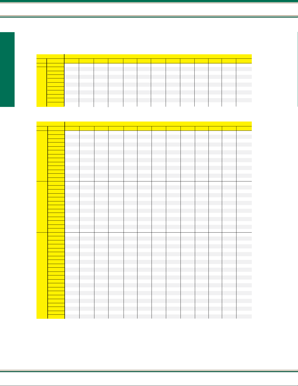
Page 21
Technical Data
70
60
50
40
30
20
10
0
170
160
150
140
130
120
11 0
100
90
80
70
60
50
40
30
20
10
0
HEAD OF WATER IN FEET
PRESSURE IN POUNDS PER SQUARE INCH
Jet Setting
Tail Pipe-35' long
Maximum Possible
Drawdown
Standing Level
Pump Capacity
100% at rated GPM
10 ft. suction lift - 80% rated GPM
15 ft. suction lift - 70% rated GPM
20 ft. suction lift - 57% rated GPM
25 ft. suction lift - 40% rated GPM
28 ft. suction lift - 25% rated GPM
29 ft. suction lift - 17% rated GPM
CENTRIFUGAL PUMPS | FORMULAS | CONVERSION FACTORS
Pump Basics
Pipe velocity (ft. per second) = =
Velocity head (feet) =
Water horsepower =
Brake horsepower (pump) =
Efciency (pump) = =
Brake horsepower (motor) =
Pressure (lbs. per sq. in.) = =
Head feet =
.408 x GPM
–––––––––––––
(pipe diameter)
(pipe velocity ft. per second)
––––––––––––––––––––––
GPM x head in ft. x specic gravity
––––––––––––––––––––––––––––
GPM x head in ft. x specic gravity
––––––––––––––––––––––––––––
GPM x head in ft. x specic gravity
––––––––––––––––––––––––––––
Watts input x motor efciency
––––––––––––––––––––––––
Head ft. x specic gravity
–––––––––––––––––––––
2
64.4
3960
3960 x pump efciency
3960 x BHP
746
2.31'
Lbs. per sq. in. x 2.31'
–––––––––––––––––
Specic gravity
.321 x GPM
––––––––––
pipe area
2
Head ft. x
specic gravity x
.433
Lbs. per square in. = Head in ft. x .433 • Head in ft. = lbs. per sq. in. x 2.31'
WHP
––––
BHP
Pump Basics
Offset Jet Pump - Pipe Friction
When the jet pump is offset horizontally from the well site, add the following distances to the vertical lift to approximate capacity to be received.
Friction loss in feet per 100 feet offset • Friction loss is to be added to vertical lift
JET SIZE HP 1
1/3 12 8 6 4
1/2 18 12 8 6 3 2
3/4 30 22 16 11 6 4
1 30 25 16 9 6
1 1/2 13 8 5 3
2 20 13 7 5
3 13 9 6 4
Example: Vertical distance to water is 60 feet, but a 100 feet horizontal / offset (run of piping) is required. A 3/4
HP jet pump is used so the capacity should be taken from the “80' depth to water” performance.
For example: 60 feet to water + 22 feet friction loss (with 1 1/4 x 1 1/4 two pipe system) = 82 feet, which is
approximately 80 feet.
Installation of a Long Tail Pipe on Deep Well Jet Pumps
The pumping capacity of a deep well jet pump can be reduced to equalize with the well ow by installing a 35
foot tail pipe below the jet assembly.
With a tail pipe, pump delivery remains at 100% of capacity down to the ejector level. If water level falls below
that, ow decreases in proportion to drawdown as shown by gures. When delivery equals well inow, the water
level remains constant until the pump shuts off. The pump will not lose prime with this tail pipe arrangement.
1
⁄4 x 1 11⁄4 x 11⁄4 11⁄2 x 11⁄4 11⁄2 x 11⁄2 2 x 11⁄2 2 x 2 21⁄
x 2 21⁄2 x 21⁄2 3 x 21⁄2 3 x 3
2
21
Page 22
Pump Basics
Drop Cable Selection Chart
Single-Phase, Two or Three Wire Cable, 60 HZ (Service Entrance to motor)
Motor Rating Copper Wire Size
Volts HP KW 14 12 10 8 6 4 3 2 1 0 00 000 0000
115 1/2 .37 100 160 250 390 620 960 1190 1460 1780 2160 2630 3140 3770
1/2 .37 400 650 1020 1610 2510 3880 4810 5880 7170 8720
3/4 .55 300 480 760 1200 1870 2890 3580 4370 5330 6470 7870
1 .75 250 400 630 990 1540 2380 2960 3610 4410 5360 6520
Pump Basics
230 1.5 1.1 190 310 480 770 1200 1870 2320 2850 3500 4280 5240
2 1.5 150 250 390 620 970 1530 1910 2360 2930 3620 4480
3 2.2 120* 190 300 470 750 1190 1490 1850 2320 2890 3610
5 3.7 0 0 180* 280 450 710 890 1110 1390 1740 2170 2680
7.5 5.5 0 0 0 200* 310 490 610 750 930 1140 1410 1720
10 7.5 0 0 0 0 250* 390 490 600 750 930 1160 1430 1760
15 11 0 0 0 0 170* 270* 340 430 530 660 820 1020 1260
1 foot - .3048 meter
Three-Phase, Three Wire Cable, 60 HZ 200 and 300 volts (Service Entrance to motor)
Motor Rating Copper Wire Size (1)
Volts HP KW 14 12 10 8 6 4 3 2 1 0 00 000 0000
1/2 .37 710 1140 1800 2840 4420
3/4 .55 510 810 1280 2030 3160
200V 1 .75 430 690 1080 1710 2670 4140 5140
60 Hz 1.5 1.1 310 500 790 1260 1960 3050 3780
2 1.5 240 390 610 970 1520 2360 2940 3610 4430 5420
Three 3 2.2 180 290 470 740 1160 1810 2250 2760 3390 4130
Phase 5 3.7 110* 170 280 440 690 1080 1350 1660 2040 2490 3050 3670 4440
7.5 5.5 0 0 200 310 490 770 960 1180 1450 1770 2170 2600 3150
Three 10 7.5 0 0 0 230* 370 570 720 880 1090 1330 1640 1970 2390
Wire 15 11 0 0 0 160* 250* 390 490 600 740 910 1110 1340 1630
20 15 0 0 0 0 190* 300* 380 460 570 700 860 1050 1270
25 18.5 0 0 0 0 0 240* 300* 370* 460 570 700 840 1030
30 22 0 0 0 0 0 0 250* 310* 380* 470 580 700 850
1/2 .37 930 1490 2350 3700 5760 8910
3/4 .55 670 1080 1700 2580 4190 6490 8060 9860
230V 1 .75 560 910 1430 2260 3520 5460 6780 8290
60 Hz 1.5 1.1 420 670 1060 1670 2610 4050 5030 6160 7530 9170
2 1.5 320 510 810 1280 2010 3130 3890 4770 5860 7170 8780
Three 3 2.2 240 390 620 990 1540 2400 2980 3660 4480 5470 6690 8020 9680
Phase 5 3.7 140* 230 370 590 920 1430 1790 2190 2690 3290 4030 4850 5870
7.5 5.5 0 160* 260 420 650 1020 1270 1560 1920 2340 2870 3440 4160
Three 10 7.5 0 0 190* 310 490 760 950 1170 1440 1760 2160 2610 3160
Wire 15 11 0 0 0 210* 330 520 650 800 980 1200 1470 1780 2150
20 15 0 0 0 0 250* 400 500 610 760 930 1140 1380 1680
25 18.5 0 0 0 0 0 320* 400 500 610 750 920 1120 1360
30 22 0 0 0 0 0 260* 330* 410* 510 620 760 930 1130
1/2 .37 3770 6020 9460
3/4 .55 2730 4350 6850
1 .75 2300 3670 5770 9070
1.5 1.1 1700 2710 4270 6730
2 1.5 1300 2070 3270 5150 8050
460v 3 2.2 1000 1600 2520 3970 6200
60 Hz 5 3.7 590 950 1500 2360 3700 5750
7.5 5.5 420 680 1070 1690 2640 4100 5100 6260 7680
Three 10 7.5 310 500 790 1250 1960 3050 3800 4680 5750 7050
Phase 15 11 0 340* 540 850 1340 2090 2600 3200 3930 4810 5900 7110
20 15 0 0 410* 650 1030 1610 2000 2470 3040 3730 4580 5530
Three 25 18.5 0 0 0 530* 830 1300 1620 1990 2450 3010 3700 4470 5430
Wire 30 22 0 0 0 430* 680 1070 1330 1640 2030 2490 3060 3700 4500
40 30 0 0 0 0 500* 790 980 1210 1490 1830 2250 2710 3290
50 37 0 0 0 0 0 640* 800 980 1210 1480 1810 2190 2650
60 45 0 0 0 0 0 540* 670* 830* 1020 1250 1540 1850 2240
75 55 0 0 0 0 0 0 0 680* 840* 1030 1260 1520 1850
100 75 0 0 0 0 0 0 0 0 620* 760* 940* 1130 1380
125 90 0 0 0 0 0 0 0 0 0 0 740* 890* 1000*
150 110 0 0 0 0 0 0 0 0 0 0 0 760* 920*
175 130 0 0 0 0 0 0 0 0 0 0 0 0 810*
200 150 0 0 0 0 0 0 0 0 0 0 0 0 0
Lengths marked * meet the U.S. National Electrical Code ampacity only for individual conductor 75°C cable. Only the lengths without
cable. Local code requirements may vary.
meet the code for jacketed 75°C
*
CAUTION!! Use of wire sizes smaller than determined above will void warranty, since low starting voltage and early failure of the unit will result. Larger wire sizes (smaller
numbers) may always be used to improve economy of operation.
(1) If aluminum conductor is used, multiply above lengths by 0.61. Maximum allowable length of aluminum wire is considerably shorter than copper wire of same size.
22
800.292.2737 | FAX 800.832.9296 | sales@aymcdonald.com | aymcdonald.com
1-19
Page 23
Pump Basics
Pump Basics
Submersible Pumps
Submersible
Pumps
Pump Catalog -
MORE THAN A BRAND. WE’RE A FAMILY.
January 2019
23
Page 24
21000 Series
21000 Series
A.Y. McDonald offers a full line of four inch submersibles ranging from 1/3 through 5 horsepower, with ow
rates ranging from 5 to 25 GPM. Our 21000 submersibles offer peak capacity performance in 5, 7, 10, 15,
20, and 25 GPM models.
Powered by NEMA approved A.Y. McDonald stainless steel motors.
The charts on the following page will assist you in choosing the pump that meets your needs.
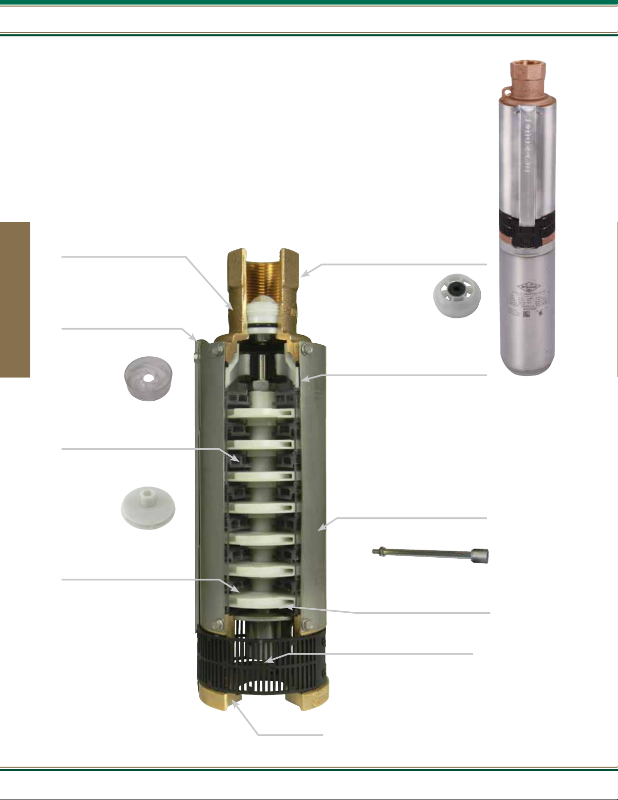
Discharge Casting
No-Lead Brass Alloy
Cable Guard
Stainless steel cable guard protects motor
leads. Angled top helps keep leads stationary
when lowering and raising submersible
pump.
Submersible Pumps
Check Valve
Acetal check valve poppet and seal housing, Buna-N
O-ring, and stainless steel washer head retention
screw. Threaded for easy installation or removal.
Working pressure of 400 PSI.
Discharge Bearing
Rubber surrounding the stainless steel
shaft provides superior wear resistance
against the harshest conditions while
maintaining shaft alignment. Self
lubricating for long life.
Diffuser
Polycarbonate durable, corrosion, and
abrasion resistant. Designed for efcient
performance and superior sand handling
capability.
Impeller
Glass Bead Acetal. This smooth and exible
material is precision
engineered for maximum performance.
- Once assembled, each
pump is individually tested to
assure performance within
design specications.
- Each pump is stamped with
the tester’s “signature” marking
to assure quality control.
- Non-corrosive in-take screen
- Cutaway illustrates features and
is not indicative of specic
model performance.
A.Y. McDonald uses it’s time proven captured
stack design. The captured stack design
incorporates sand notches into the diffusers,
which has proven, over time, to keep sand
owing thru the stack.
Polished Stainless Steel Shell
Heavy duty and threaded at both ends for
easy eld service.
Shaft
7/16” 300 series stainless steel, hex design
for positive impeller drive. Each shaft
individually measured for straightness with
strict tolerances.
Stainless steel motor coupling.
Motor Bracket
No-Lead Brass Alloy
24
800.292.2737 | FAX 800.832.9296 | sales@aymcdonald.com | aymcdonald.com
1-19
Page 25
How to Order 4” Submersible Pumps
Order by Model Number - Example: 21050K3A
21000 Series
21 050 K 3
Pump Model
21 - No-Lead Brass
22 - Thermoplastic
23 - Domestic Stainless Steel
24 - Stainless Steel
Model 21050K3A is a 1/2 HP, three wire, 115 volt, single phase no-lead brass
4" submersible pump, designed to pump in the 10 GPM range.
Horsepower
030 - 1/3 HP
050 - 1/2 HP
075 - 3/4 HP
100 - 1 HP
150 - 1 1/2 HP
200 - 2 HP
300 - 3 HP
500 - 5 HP
NOTES
- Standard is 230V, Single Phase, 60 HZ (no sufx letter required)
- Two-Wire Single phase models include; pump, motor, leads
- Three-Wire Single phase models include; pump, motor, leads, and control box
- Three-Wire Three phase models include; pump, motor, leads, and starter kit
- All submersible pumps include internal check valves and ground lead on motor.
Series
J Series - 5 GPM
V Series - 7 GPM
K Series - 10 GPM
L Series - 15 GPM
P Series - 20 GPM
M Series - 25 GPM
Wires
Two wire or
Three wire
A
Other Controls
Leave blank for 230V
60 HZ, Single Phase (Standard)
A - 115V Single Phase
Other Options Contact Factory
Z - 230V Three Phase
Y - 460V Three Phase
Leave blank for
Control (Standard)
LB - Less box
(Single Phase Option)
LS - Less starter
(Three Phase Option)
Submersible Pumps
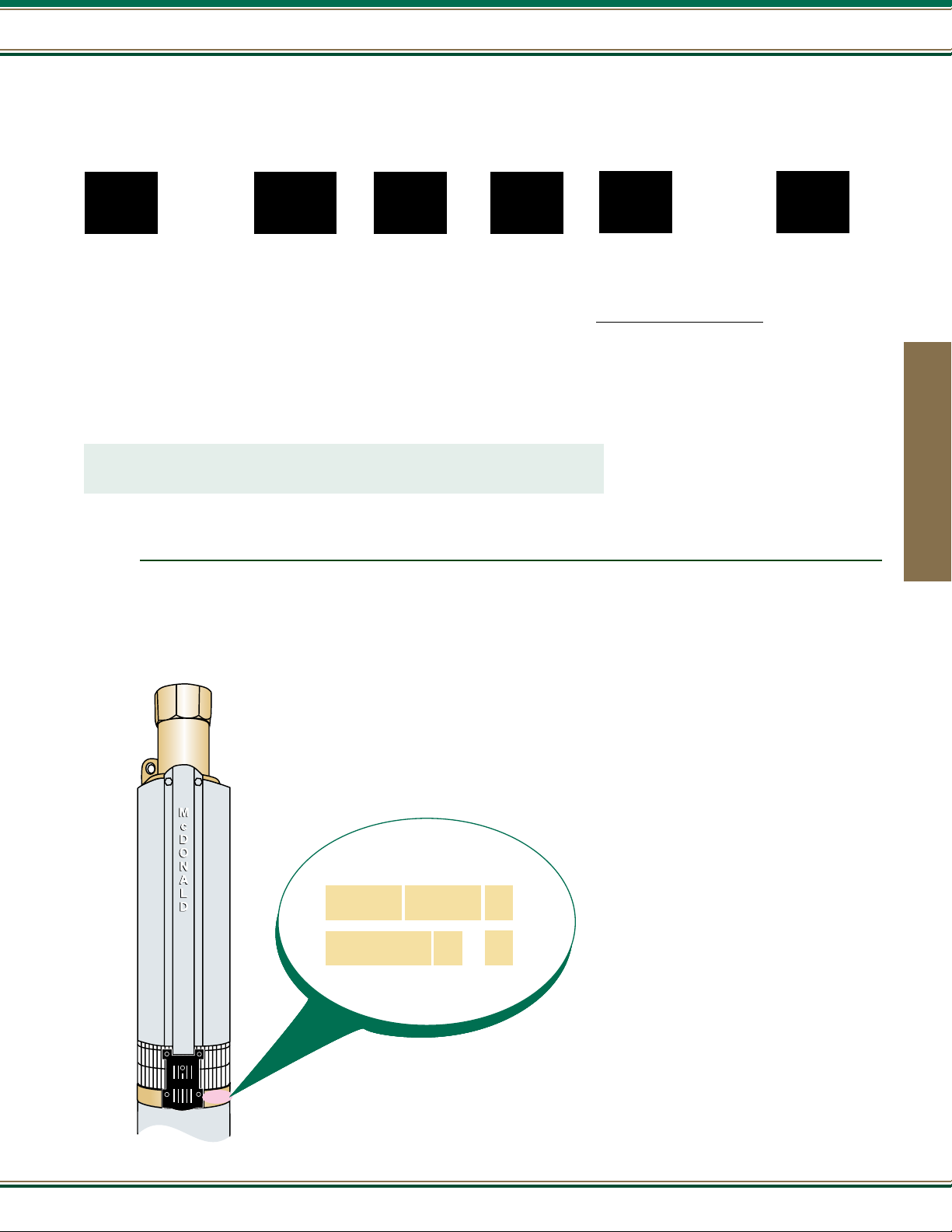
Locating the code number on the pump
K18050K
230V2 X
EXAMPLE
Date Code
Motor HP
Pump
Series
K18 050 K
230V 2 X
Voltage
No. of
Power
Leads
Assembler’s
Code
A code is stamped on each A.Y. McDonald
submersible pump. Contained in this code is the
following information:
- Date of manufacture
- Motor HP
- Pump Series
- Voltage
- Number of power leads
- Assembler’s code
25
Page 26

21000 Series
M
c
D
O
N
A
L
D
A
B
J Series - 5 GPM
A.Y. McDonald offers a full line of no-lead brass submersible pumps built for years of trouble free operation, with high-efciency impellers
and diffusers. These submersibles offer peak capacity performance in 5, 7, 10, 15, 20, and 25 gallons per minute (GPM). Other features
include no-lead discharge head with a built-in check valve, and stainless steel shaft and coupling.
All J Series No-Lead Pumps come with a 1 1/4” discharge and sizes range from 1/3 to 1 1/2 horse power (HP). Two or three wire models
up to 1 1/2 horse power (HP).
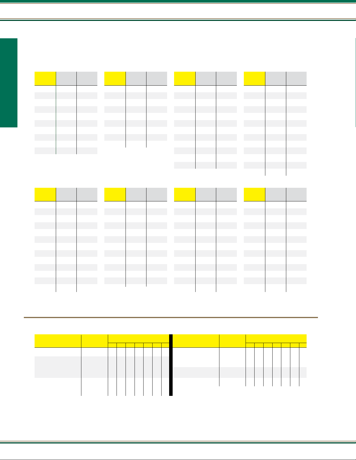
Two Wire Single Phase
Model No. HP Stages Volt A B Wt.
21030J2A* 1/3 9 115 13.48" 9.53" 26
21030J2* 1/3 9 230 13.48" 9.53" 26
21050J2A 1/2 13 115 16.68" 9.53" 30
21050J2 1/2 13 230 16.68" 9.53" 30
21075J2 3/4 18 230 20.67" 10.66" 36
21100J2 1 23 230 25.93" 11.75" 41
21150J2 1 1/2 30 230 31.45" 15.12" 49
Three Wire** Single Phase
Model No. HP Stages Volt A B Wt.
Submersible Pumps
21030J3A* 1/3 9 115 13.48" 9.53" 26
21030J3* 1/3 9 230 13.48" 9.53" 26
21050J3A 1/2 13 115 16.68" 9.53" 30
21050J3 1/2 13 230 16.68" 9.53" 30
21075J3 3/4 18 230 20.67" 10.66" 36
21100J3 1 23 230 25.93" 11.75" 41
21150J3 1 1/2 30 230 31.45" 13.28" 41
Three Wire Three Phase
Model No. HP Stages Volt A B Wt.
21150J3Z 1 1/2 30 230 31.45" 11.75" 45
Pump end
discharge
1 1/4" FNPT
3 3/4" diameter
with cable guard
4” No-Lead Brass Pump Ends
Model No. HP Wt.
21030J 1/3 10
21050J 1/2 11
21075J 3/4 13
21100J 1 15
21150J 1 1/2 18
26
* All one-third horsepower pumps are furnished with one-half horsepower motors (and control boxes where applicable).
** All three wire pumps are available in three phase by selecting pump end and appropriate motor and starter kit (see pages 108-118).
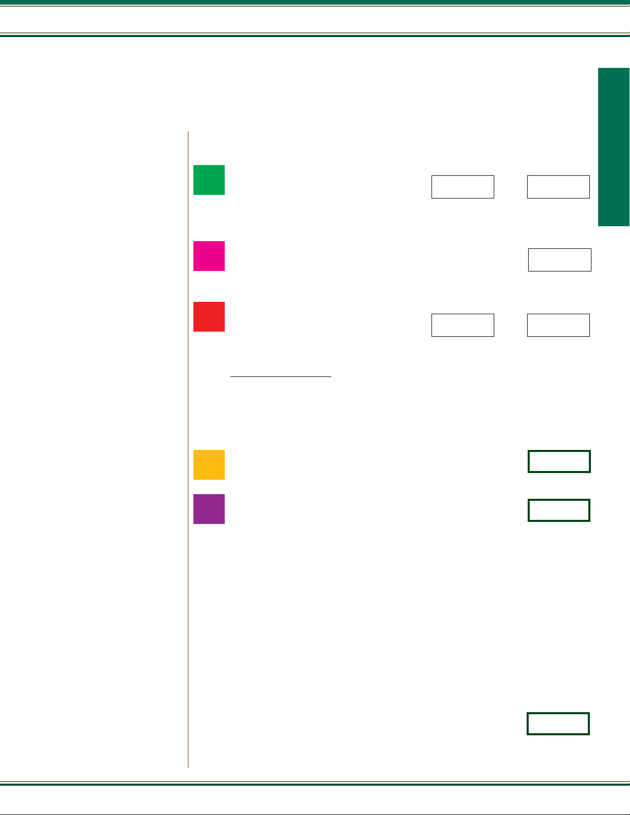
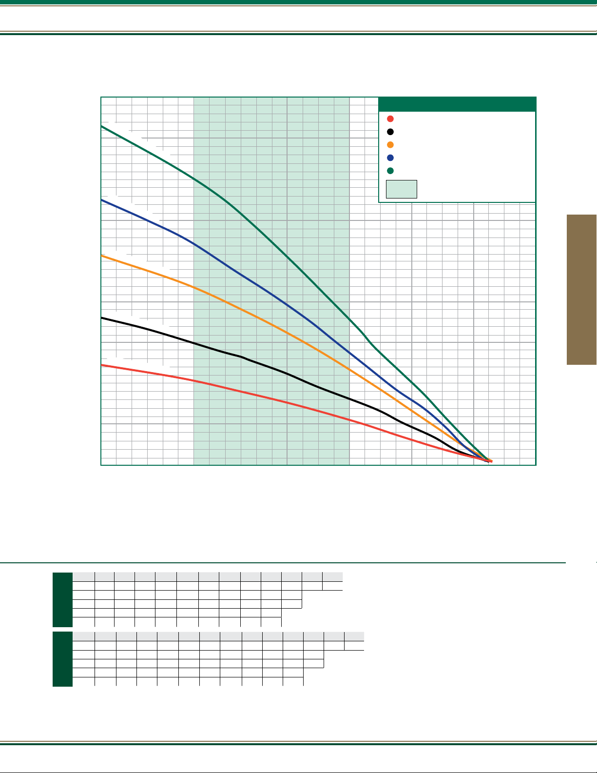
Output
1/3
1/2
3/4
- in Gallons Per Minute (Depth to Water)
PSI 25’ 50’ 75’ 100’ 125’ 150’ 175’ 200’ 225’
0 11.7 10.6 9.5 8.4 7.3 6.1 4.8 3.4 1.8
30 8.6 7.5 6.4 5.1 3.8 2.2
40 7.6 6.4 5.2 3.9 2.3
HP
50 6.5 5.3 4.0 2.5
PSI 25’ 50’ 75’ 100’ 125’ 150’ 175’ 200’ 225’ 250’ 275’ 300’ 325’
0 11.9 11.2 10.5 9.8 9.1 8.4 7.6 6.8 6.0 5.0 4.1 3.0 1.8
30 10.0 9.2 8.5 7.8 7.0 6.1 5.3 4.3 3.2 2.1
40 9.3 8.6 7.8 7.0 6.2 5.3 4.4 3.3 2.2
HP
50 8.6 7.9 7.1 6.3 5.4 4.4 3.4 2.3
60 7.9 7.2 6.3 5.5 4.5 3.5 2.3
PSI 25’ 50’ 75’ 100’ 125’ 150’ 175’ 200’ 225’ 250’ 275’ 300’ 325’ 350’ 375’ 400’ 425’ 450’
0 12.2 11.7 11.2 10.7 10.2 9.7 9.2 8.7 8.1 7.6 7.1 6.5 5.9 5.3 4.7 4.0 3.3 2.6
30 10.8 10.3 9.8 9.3 8.8 8.3 7.7 7.2 6.6 6.1 5.5 4.9 4.2 3.5 2.7 1.9
40 10.3 9.8 9.3 8.8 8.3 7.8 7.2 6.7 6.1 5.5 4.9 4.3 3.6 2.8 2.0
HP
50 9.9 9.4 8.9 8.3 7.8 7.3 6.7 6.2 5.6 4.9 4.3 3.6 2.9 2.0
60 9.4 8.9 8.4 7.9 7.3 6.8 6.2 5.6 5.0 4.4 3.7 2.9 2.1
FRICTION LOSSES IN RISER PIPE
HAVE NOT BEEN CALCULATED
800.292.2737 | FAX 800.832.9296 | sales@aymcdonald.com | aymcdonald.com
1-19
Page 27
J Series - 5 GPM
21000 Series
900
1
1
/
2
H
800
700
600
500
400
TOTAL HEAD IN FEET
300
200
P
•
3
0
1
H
P
•
2
3
S
t
a
g
3
/
4
H
P
•
1
8
S
1
/
2
H
P
•
1
3
S
1
/
3
H
P
•
9
S
t
SHUTOFF HEAD
1/3 HP 245 FT. • 106 P.S.I.
1/2 HP 361 FT. • 156 P.S.I.
S
t
a
g
e
s
e
s
t
a
g
e
s
t
a
g
e
s
a
g
e
s
3/4 HP 512 FT. • 222 P.S.I.
1 HP 649 FT. • 281 P.S.I.
1 1/2 HP 829 FT. • 359 P.S.I.
Most efcient operating range
Submersible Pumps
100
0 2 4 6 8 10 12 14
U.S. GALLONS PER MINUTE
PSI 50’ 100’ 150’ 200’ 250’ 300’ 350’ 400’ 450’ 500’ 550’ 600’
0 11.7 10.9 10.1 9.3 8.4 7.6 6.7 5.8 4.9 3.9 2.7 1.5
30 10.6 9.8 9.0 8.1 7.3 6.4 5.5 4.5 3.4 2.3
1
40 10.2 9.4 8.6 7.7 6.9 6.0 5.0 4.0 2.9 1.7
HP
50 9.9 9.0 8.2 7.3 6.4 5.5 4.6 3.5 2.4
60 9.5 8.6 7.8 6.9 6.0 5.1 4.1 3.0 1.8
PSI 50’ 100’ 150’ 200’ 250’ 300’ 350’ 400’ 450’ 500’ 550’ 600’ 650’
0 15.9 15.1 14.3 13.4 12.4 11.4 10.4 9.2 7.9 6.5 5.0 3.4 1.6
30 14.8 13.9 13.0 12.1 11.0 9.9 8.7 7.4 5.9 4.4 2.7
1½
40 14.4 13.5 12.6 11.6 10.5 9.4 8.1 6.7 5.2 3.6 1.9
HP
50 14.0 13.1 12.1 11.1 10.0 8.8 7.5 6.0 4.5 2.8
60 13.6 12.7 11.7 10.6 9.5 8.2 6.8 5.3 3.7 2.0
FRICTION LOSSES IN RISER PIPE HAVE NOT BEEN CALCULATED
27
Page 28
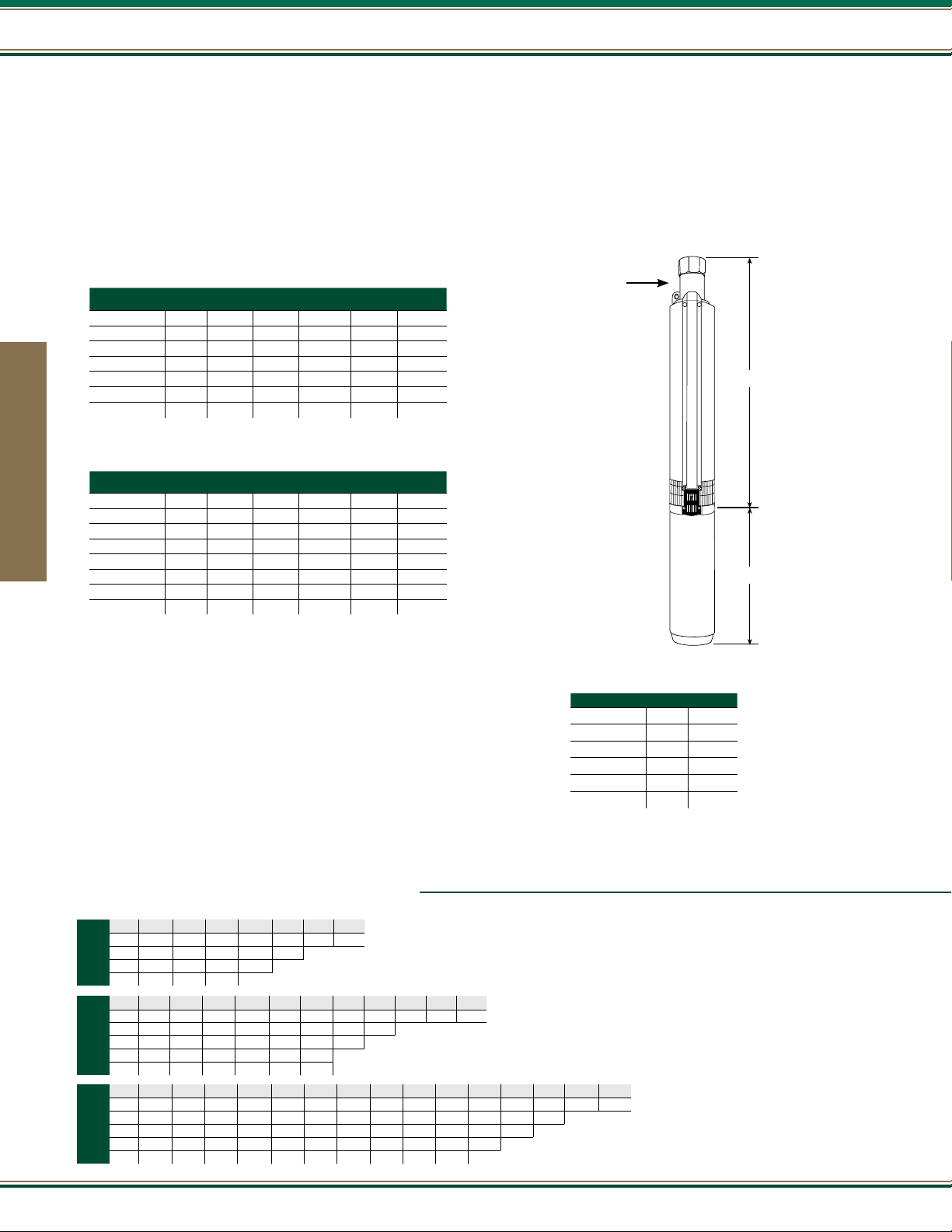
21000 Series
M
c
D
O
N
A
L
D
A
B
V Series - 7 GPM
A.Y. McDonald offers a full line of no-lead brass submersible pumps built for years of trouble free operation, with high-efciency impellers
and diffusers. These submersibles offer peak capacity performance in 5, 7, 10, 15, 20, and 25 gallons per minute (GPM). Other features
include no-lead discharge head with a built-in check valve, and stainless steel shaft and coupling.
All V Series No-Lead Pumps come with a 1 1/4” discharge and sizes range from 1/3 to 2 horse power (HP). Two wire models up to 1 1/2
horse power (HP) or three wire models up to 2 horse power (HP).
Two Wire Single Phase
Model No. HP Stages Volt A B
21030V2A* 1/3 6 115 11.1" 9.53" 24
21030V2* 1/3 6 230 11.1" 9.53" 25
21050V2A 1/2 9 115 13.48" 9.53" 26
21050V2 1/2 9 230 13.48" 9.53" 26
21075V2 3/4 12 230 15.92" 10.66" 31
21100V2 1 16 230 19.11" 11.75" 34
21150V2 1 1/2 21 230 23.58" 15.12" 46
Three Wire** Single Phase
Model No. HP Stages Volt A B WT.
21030V3A* 1/3 6 115 11.1" 9.53" 25
Submersible Pumps
21030V3* 1/3 6 230 11.1" 9.53" 25
21050V3A 1/2 9 115 13.48" 9.53" 26
21050V3 1/2 9 230 13.48" 9.53" 26
21075V3 3/4 12 230 15.92" 10.66" 30
21100V3 1 16 230 19.11" 11.75" 35
21150V3 1 1/2 21 230 23.58" 13.62" 41
21200V3 2 26 230 28.34" 15.12" 49
WT.
Pump end
discharge
1 1/4" FNPT
3 3/4" diameter
with cable guard
4” No-Lead Brass Pump Ends
Model No. HP
21030V 1/3 9
21050V 1/2 10
21075V 3/4 13
21100V 1 11
21150V 1 1/2 16
21200V 2 18
WT.
28
* All one-third horsepower pumps are furnished with one-half horsepower motors (and control boxes where applicable).
** All three wire pumps are available in three phase by selecting pump end and appropriate motor and starter kit (see pages 108-118).
Output
1/3
1/2
3/4
- in Gallons Per Minute (Depth to Water)
PSI 25’ 50’ 75’ 100’ 125’ 150’ 175’
0 15.1 13.7 12.2 10.5 8.6 6.4 3.8
30 10.9 9.0 6.9 4.4 1.3
HP
40 9.2 7.1 4.6 1.6
50 7.2 4.8 1.9
PSI 25’ 50’ 75’ 100’ 125’ 150’ 175’ 200’ 225’ 250’ 275’
0 15.6 14.6 13.6 12.6 11.5 10.4 9.2 7.8 6.3 4.5 2.5
30 12.8 11.8 10.7 9.5 8.2 6.7 5.0 3.0
40 11.9 10.8 9.6 8.3 6.8 5.1 3.1
HP
50 10.9 9.7 8.4 6.9 5.2 3.3
60 9.8 8.5 7.0 5.4 3.4 1.3
PSI 25’ 50’ 75’ 100’ 125’ 150’ 175’ 200’ 225’ 250’ 275’ 300’ 325’ 350’ 375’
0 16.1 15.5 14.8 14.0 13.3 12.5 11.6 10.8 9.9 8.9 7.8 6.7 5.5 4.2 2.8
30 14.2 13.4 12.7 11.8 11.0 10.1 9.1 8.1 7.0 5.8 4.5 3.1 1.5
40 13.5 12.7 11.9 11.0 10.1 9.2 8.2 7.1 5.9 4.6 3.2 1.7
HP
50 12.8 12.0 11.1 10.2 9.3 8.2 7.2 6.0 4.7 3.3 1.8
60 12.0 11.2 10.3 9.3 8.3 7.2 6.1 4.8 3.4 1.9
FRICTION LOSSES IN RISER PIPE HAVE NOT
BEEN CALCULATED
800.292.2737 | FAX 800.832.9296 | sales@aymcdonald.com | aymcdonald.com
1-19
Page 29
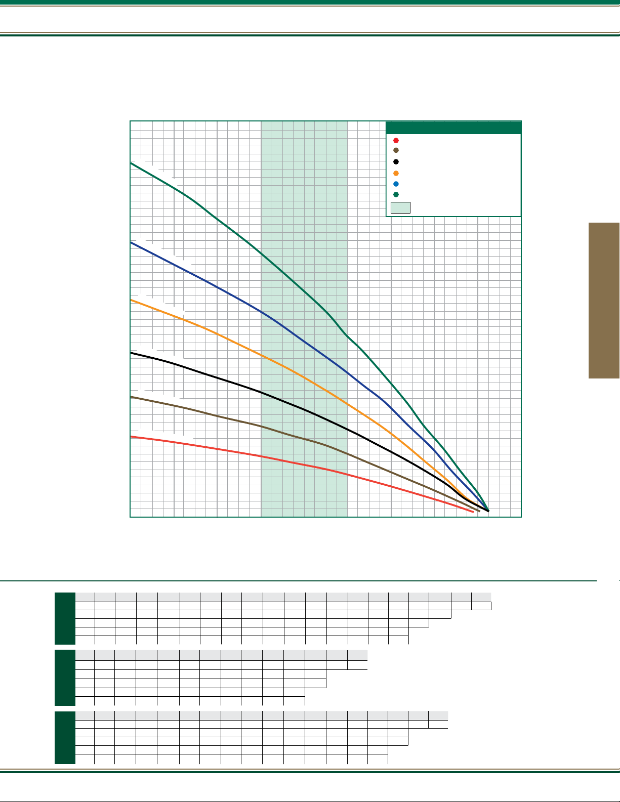
V Series - 7 GPM
21000 Series
1000
2
900
H
P
•
2
6
S
t
a
g
e
800
1
700
1
/
2
H
P
•
2
1
600
1
H
P
•
1
6
S
t
500
a
TOTAL HEAD IN FEET
3
/
4
H
P
•
1
400
300
1
2
/
2
H
P
•
9
S
SHUTOFF HEAD
1/3 HP 204 FT. • 88 P.S.I.
1/2 HP 305 FT. • 132 P.S.I.
3/4 HP 416 FT. • 180 P.S.I.
1 HP 548 FT. • 237 P.S.I.
1 1/2 HP 695 FT. • 301 P.S.I.
2 HP 896 FT. • 388 P.S.I.
Most efcient operating range
S
t
a
g
e
g
e
S
t
a
g
e
t
a
g
e
Submersible Pumps
1
/
3
H
P
•
6
S
t
200
100
0 2 4 6 8 10 12 14 16 18
a
g
e
U.S. GALLONS PER MINUTE
PSI 25’ 50’ 75’ 100’ 125’ 150’ 175’ 200’ 225’ 250’ 275’ 300’ 325’ 350’ 375’ 400’ 425’ 450’ 475’
0 16.1 15.5 15.0 14.4 13.9 13.3 12.8 12.2 11.6 11.0 10.3 9.6 8.9 8.1 7.2 6.3 5.4 4.5 3.5
1
30 14.5 14.0 13.5 12.9 12.3 11.8 11.1 10.5 9.8 9.1 8.3 7.4 6.6 5.6 4.7 3.7 2.7
40 14.0 13.5 12.9 12.4 11.8 11.2 10.5 9.9 9.1 8.3 7.5 6.6 5.7 4.7 3.8 2.8
HP
50 13.5 13.0 12.4 11.8 11.2 10.6 9.9 9.2 8.4 7.6 6.7 5.8 4.8 3.8 2.8
60 13.0 12.5 11.9 11.3 10.6 10.0 9.2 8.5 7.6 6.8 5.8 4.9 3.9 2.9 1.9
PSI 50’ 100’ 150’ 200’ 250’ 300’ 350’ 400’ 450’ 500’ 550’ 600’ 650’
0 15.9 15.1 14.3 13.4 12.4 11.4 10.4 9.2 7.9 6.5 5.0 3.4 1.6
30 14.8 13.9 13.0 12.1 11.0 9.9 8.7 7.4 5.9 4.4 2.7
1½
40 14.4 13.5 12.6 11.6 10.5 9.4 8.1 6.7 5.2 3.6 1.9
HP
50 14.0 13.1 12.1 11.1 10.0 8.8 7.5 6.0 4.5 2.8
60 13.6 12.7 11.7 10.6 9.5 8.2 6.8 5.3 3.7 2.0
PSI 50’ 100’ 150’ 200’ 250’ 300’ 350’ 400’ 450’ 500’ 550’ 600’ 650’ 700’ 750’ 800’ 850’
0 16.1 15.4 14.7 14.0 13.3 12.6 11.8 11.0 10.2 9.3 8.4 7.4 6.4 5.3 4.1 2.9 1.5
2
30 15.1 14.5 13.8 13.0 12.3 11.5 10.7 9.8 8.9 8.0 7.0 6.0 4.9 3.7 2.3
40 14.8 14.1 13.4 12.7 11.9 11.1 10.3 9.4 8.5 7.6 6.5 5.5 4.3 3.1 1.7
HP
50 14.5 13.8 13.1 12.3 11.5 10.7 9.9 9.0 8.1 7.1 6.1 4.9 3.8 2.4
60 14.2 13.5 12.7 12.0 11.2 10.3 9.5 8.6 7.6 6.6 5.6 4.4 3.2 1.8
FRICTION LOSSES IN RISER PIPE HAVE NOT
BEEN CALCULATED
29
Page 30
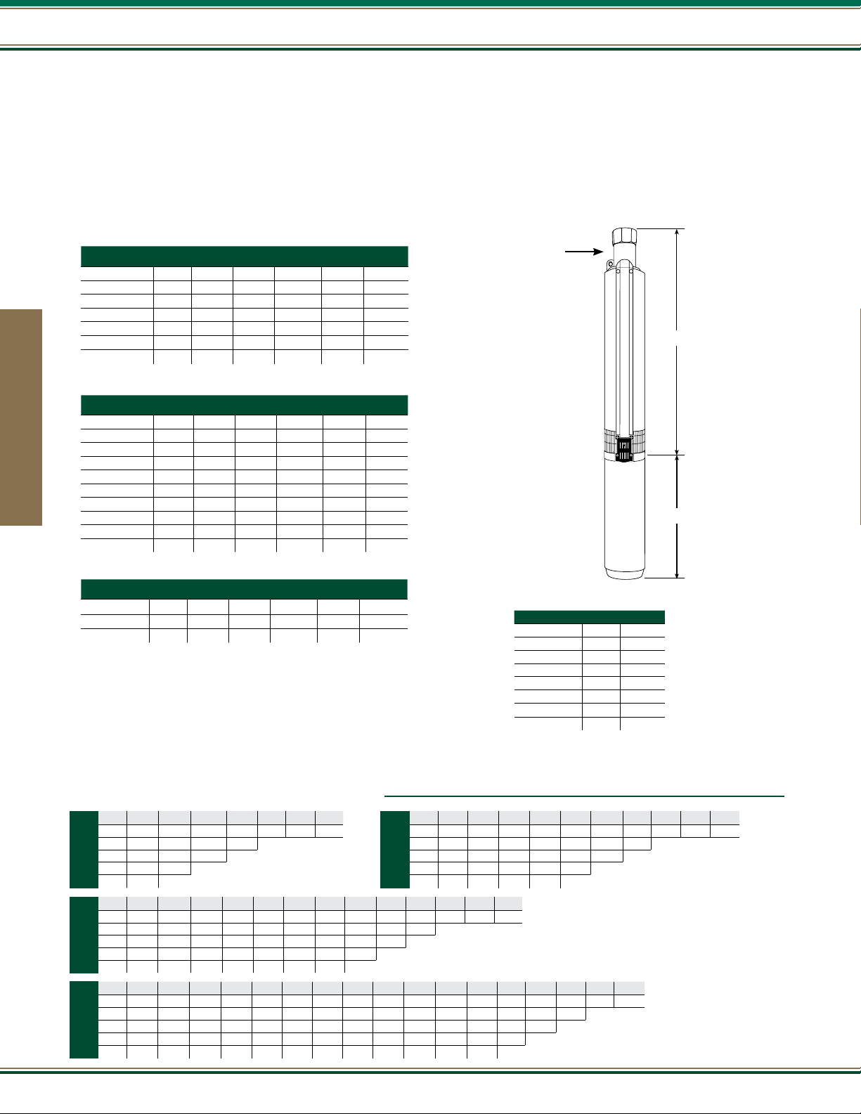
21000 Series
M
c
D
O
N
A
L
D
A
B
K Series - 10 GPM
A.Y. McDonald offers a full line of no-lead brass submersible pumps built for years of trouble free operation, with high-efciency impellers and
diffusers. These submersibles offer peak capacity performance in 5, 7, 10, 15, 20, and 25 gallons per minute (GPM). Other features include
no-lead discharge head with a built-in check valve, and stainless steel shaft and coupling.
All K Series No-Lead Pumps come with a 1 1/4” discharge and sizes range from 1/3 to 5 horse power (HP). Two wire models up to 1 1/2 horse
power (HP) or three wire models up to 5 horse power (HP).
Two Wire Single Phase
Model No. HP Stages Volt A B
21030K2A* 1/3 5 115 12.01" 9.53" 19
21030K2* 1/3 5 230 12.01" 9.53" 19
21050K2A 1/2 7 115 13.65" 9.53" 19
21050K2 1/2 7 230 13.65" 9.53" 27
21075K2 3/4 9 230 15.34" 10.66" 29
21100K2 1 12 230 17.89" 11.75" 32
21150K2 1 1/2 16 230 22.55" 15.12" 42
Three Wire** Single Phase
Model No. HP Stages Volt A B WT.
21030K3A* 1/3 5 115 12.01" 9.53" 19
21030K3* 1/3 5 230 12.01" 9.53" 19
21050K3A 1/2 7 115 13.65" 9.53" 19
Submersible Pumps
21050K3 1/2 7 230 13.65" 9.53" 19
21075K3 3/4 9 230 15.34" 10.66" 29
21100K3 1 12 230 17.89" 11.75" 33
21150K3 1 1/2 16 230 22.55" 13.62" 38
21200K3 2 20 230 25.95" 15.12" 46
21300K3 3 26 230 31.06" 19.06" 70
21500K3 5 33 230 36.99” 29.62” 91
Three Wire** Three Phase
Model No. HP Stages Volt A B WT.
21150K3Z 1 1/2 16 230 22.55" 11.75" 35
21200K3Z 2 20 230 25.98" 13.62" 43
21300K3Z 3 26 230 31.06" 16.04" 60
WT.
Pump end
discharge
1 1/4" FNPT
3 3/4" diameter
with cable guard
4” No-Lead Brass Pump Ends
Model No. HP
21030K 1/3 7
21050K 1/2 8
21075K 3/4 9
21100K 1 10
21150K 1 1/2 13
21200K 2 15
21300K 3 17
21500K 5 19
WT.
30
* All one-third horsepower pumps are furnished with one-half horsepower motors (and control boxes where applicable).
** All three wire pumps are available in three phase by selecting pump end and appropriate motor and starter kit (see pages 108-118).
Output
1/3
3/4
- in Gallons Per Minute (Depth to Water)
PSI 25’ 50’ 75’ 100’ 125’ 150’ 175’
0 18.78 16.62 14.27 11.68 8.75 5.31 0.93
30 12.29 9.45 6.16 2.06
40 9.68 6.43 2.42
HP
50 6.70 2.76
60 3.10
PSI 25’ 50’ 75’ 100’ 125’ 150’ 175’ 200’ 225’ 250’ 275’ 300’ 325’
0 20.36 19.26 18.12 16.93 15.67 14.35 12.95 11.45 9.83 8.05 6.06 3.75 0.89
30 17.20 15.97 14.66 13.28 11.80 10.21 8.47 6.54 4.31 1.61
40 16.06 14.76 13.39 11.92 10.34 8.61 6.69 4.49 1.84
HP
50 14.86 13.49 12.03 10.46 8.75 6.85 4.67 2.07
60 13.60 12.15 10.59 8.89 7.00 4.85 2.29
PSI 25’ 50’ 75’ 100’ 125’ 150’ 175’ 200’ 225’ 250’ 275’ 300’ 325’ 350’ 375’ 400’ 425’
0 20.86 20.05 19.22 18.36 17.47 16.55 15.60 14.61 13.57 12.48 11.33 10.10 8.79 7.37 5.81 4.06 2.00
30 18.56 17.68 16.77 15.82 14.84 13.81 12.73 11.59 10.39 9.10 7.71 6.18 4.48 2.51 0.09
1
40 17.75 16.84 15.89 14.91 13.89 12.81 11.68 10.48 9.20 7.82 6.30 4.61 2.67 0.29
HP
50 16.91 15.97 14.99 13.97 12.90 11.77 10.58 9.30 7.93 6.42 4.75 2.83 0.50
60 16.04 15.06 14.05 12.98 11.86 10.67 9.40 8.04 6.54 4.89 2.99 0.70
PSI 25’ 50’ 75’ 100’ 125’ 150’ 175’ 200’ 225’ 250’
0 19.90 18.49 16.99 15.40 13.69 11.84 9.79 7.49 4.78 1.32
30 15.77 14.09 12.27 10.28 8.04 5.44 2.21
1/2
40 14.22 12.42 10.44 8.22 5.66 2.49
HP
50 12.56 10.60 8.40 5.87 2.76
60 10.75 8.58 6.08 3.03
FRICTION LOSSES IN RISER PIPE HAVE
NOT BEEN CALCULATED
800.292.2737 | FAX 800.832.9296 | sales@aymcdonald.com | aymcdonald.com
1-19
Page 31

K Series - 10 GPM
1400
5
H
P
1300
1200
1100
1000
900
•
3
3
S
t
a
g
e
s
3
H
P
•
2
6
S
t
a
g
e
s
21000 Series
SHUTOFF HEAD
1/3 HP 180 FT. • 78 P.S.I.
1/2 HP 259 FT. • 112 P.S.I.
3/4 HP 333 FT. • 144 P.S.I.
1 HP 448 FT. • 194 P.S.I.
1 1/2 HP 591 FT. • 256 P.S.I.
2 HP 758 FT. • 328 P.S.I.
3 HP 1042 FT. • 451 P.S.I.
5 HP 1331 FT. • 576 P.S.I.
Most efcient operating range
800
2
H
P
•
2
0
S
t
a
g
e
700
TOTAL HEAD IN FEET
1
600
1
500
1
400
3
300
1
/
200
1
/
100
0 2 4 6 8 10 12 14 16 18 20 22
s
/
2
H
P
•
1
6
S
t
a
g
e
s
H
P
•
1
2
S
t
a
g
e
s
/
4
H
P
•
9
S
t
a
g
e
s
2
H
P
•
7
S
t
a
g
e
s
3
H
P
•
5
S
t
a
g
e
s
U.S. GALLONS PER MINUTE
Output
- in Gallons Per Minute (Depth to Water) - Continued
PSI 50’ 100’ 150’ 200’ 250’ 300’ 350’ 400’ 450’ 500’ 550’
0 20.18 18.95 17.66 16.31 14.87 13.34 11.69 9.89 7.88 5.58 2.80
30 18.46 17.15 15.76 14.29 12.72 11.01 9.14 7.03 4.58 1.51
1½
40 17.86 16.52 15.09 13.58 11.95 10.17 8.20 5.95 3.27
HP
50 17.25 15.87 14.41 12.84 11.15 9.29 7.20 4.78 1.78
60 16.62 15.21 13.70 12.08 10.31 8.36 6.14 3.49 0.02
PSI 50’ 100’ 150’ 200’ 250’ 300’ 350’ 400’ 450’ 500’ 550’ 600’ 650’ 700’ 750’
0 19.85 18.89 17.89 16.85 15.78 14.66 13.49 12.26 10.96 9.59 8.11 6.51 4.75 2.77 0.46
30 18.51 17.49 16.44 15.35 14.21 13.02 11.77 10.44 9.03 7.51 5.85 4.02 1.93
2
40 18.04 17.01 15.94 14.83 13.67 12.45 11.17 9.80 8.34 6.76 5.03 3.09 0.84
HP
50 17.57 16.52 15.44 14.30 13.11 11.87 10.55 9.14 7.63 5.98 4.16 2.10
FRICTION LOSSES IN RISER PIPE HAVE
NOT BEEN CALCULATED
60 17.09 16.03 14.92 13.76 12.55 11.27 9.91 8.46 6.89 5.17 3.25 1.02
PSI 50’ 100’ 150’ 200’ 250’ 300’ 350’ 400’ 450’ 500’ 550’ 600’ 650’ 700’ 750’ 800’ 850’ 900’ 950’ 1000’
0 21.05 20.27 19.48 18.67 17.84 16.99 16.11 15.22 14.30 13.35 12.36 11.35 10.30 9.20 8.05 6.85 5.59 4.24 2.81 1.26
30 19.97 19.17 18.35 17.51 16.65 15.77 14.87 13.93 12.97 11.98 10.95 9.88 8.76 7.60 6.37 5.08 3.70 2.23 0.62
3
40 19.60 18.79 17.96 17.12 16.25 15.36 14.44 13.49 12.52 11.51 10.46 9.37 8.23 7.04 5.78 4.45 3.03 1.50
HP
50 19.23 18.41 17.58 16.72 15.84 14.94 14.01 13.05 12.05 11.03 9.96 8.85 7.69 6.47 5.18 3.81 2.34 0.75
60 18.85 18.03 17.18 16.32 15.43 14.51 13.57 12.59 11.58 10.54 9.45 8.32 7.13 5.88 4.56 3.14 1.62
PSI 50’ 100’ 150’ 200’ 250’ 300’ 350’ 400’ 450’ 500’ 550’ 600’ 650’ 700’ 750’ 800’ 850’ 900’ 950’ 1000’ 1050’ 1100’ 1150’ 1200’ 1250’ 1300’
0 20.96 20.39 19.81 19.22 18.62 18.01 17.38 16.74 16.09 15.42 14.74 14.04 13.32 12.58 11.82 11.04 10.22 9.38 8.51 7.60 6.64 5.64 4.58 3.45 2.24 0.93
30 20.17 19.59 18.99 18.39 17.77 17.14 16.49 15.84 15.16 14.47 13.77 13.04 12.29 11.52 10.73 9.90 9.05 8.16 7.23 6.26 5.24 4.15 3.00 1.75 0.39
5
40 19.90 19.31 18.71 18.10 17.48 16.84 16.19 15.53 14.85 14.15 13.43 12.70 11.94 11.16 10.35 9.51 8.64 7.74 6.79 5.80 4.75 3.63 2.43 1.14
HP
50 19.63 19.04 18.43 17.82 17.19 16.54 15.89 15.21 14.53 13.82 13.09 12.35 11.58 10.79 9.97 9.11 8.23 7.31 6.34 5.32 4.24 3.09 1.85 0.50
60 19.36 18.76 18.15 17.53 16.89 16.24 15.58 14.90 14.20 13.49 12.75 12.00 11.22 10.41 9.58 8.71 7.81 6.86 5.87 4.83 3.72 2.53 1.24
Submersible Pumps
31
Page 32

21000 Series
M
c
D
O
N
A
L
D
A
B
L Series - 15 GPM
A.Y. McDonald offers a full line of no-lead brass submersible pumps built for years of trouble free operation, with high-efciency impellers and
diffusers. These submersibles offer peak capacity performance in 5, 7, 10, 15, 20, and 25 gallons per minute (GPM). Other features include
no-lead discharge head with a built-in check valve, and stainless steel shaft and coupling.
All L Series No-Lead Pumps come with a 1 1/4” discharge and sizes range from 1/3 to 5 horse power (HP). Two wire models up to 1 1/2 horse
power (HP) or three wire models up to 5 horse power (HP).
Two Wire Single Phase
Model No. HP Stages Volt A B
21030L2A* 1/3 5 115 13.52" 9.53" 26
21030L2* 1/3 5 230 13.52" 9.53" 26
21050L2A 1/2 6 115 14.59" 9.53" 26
21050L2 1/2 6 230 14.59" 9.53" 26
21075L2 3/4 8 230 16.75" 10.66" 30
21100L2 1 10 230 18.89" 11.75" 34
21150L2 1 1/2 13 230 22.11" 15.12" 42
Three Wire** Single Phase
Model No. HP Stages Volt A B WT.
21030L3A* 1/3 5 115 13.52" 9.53" 26
21030L3* 1/3 5 230 13.52" 9.53" 26
21050L3A 1/2 6 115 14.59" 9.53" 26
Submersible Pumps
21050L3 1/2 6 230 14.59" 9.53" 26
21075L3 3/4 8 230 16.75" 10.66" 30
21100L3 1 10 230 18.89" 11.75" 34
21150L3 1 1/2 13 230 22.11" 13.62" 39
21200L3 2 17 230 26.41" 15.12" 46
21300L3 3 23 230 34.23" 19.06" 60
21500L3 5 35 230 47.10” 29.62” 87
Three Wire** Three Phase
Model No. HP Stages Volt A B WT.
21200L3Z 2 17 230 26.41" 13.62" 43
21300L3Z 3 23 230 34.23" 16.04" 53
21500L3Z 5 35 230 47.10” 23.62” 74
WT.
Pump end
discharge
1 1/4" FNPT
3 3/4" diameter
with cable guard
4” No-Lead Brass Pump Ends
Model No. HP
21030L 1/3 8
21050L 1/2 9
21075L 3/4 10
21100L 1 11
21150L 1 1/2 11
21200L 2 13
21300L 3 17
21500L 5 24
WT.
32
* All one-third horsepower pumps are furnished with one-half horsepower motors (and control boxes where applicable).
** All three wire pumps are available in three phase by selecting pump end and appropriate motor and starter kit (see pages 108-118).
Output
- in Gallons Per Minute (Depth to Water)
PSI 25’ 50’ 75’ 100’ 125’
0 27.82 24.66 21.05 16.70 10.79
1/3
30 17.79 12.38
HP
40 12.86 2.69
50 4.29
PSI 25’ 50’ 75’ 100’ 125’ 150’ 175’ 200’ 225’
0 28.58 26.69 24.66 22.46 20.05 17.33 14.17 10.21 4.08
30 22.98 20.62 17.98 14.94 11.22 5.91
3/4
40 20.81 18.19 15.19 11.54 6.43
HP
50 18.40 15.44 11.85 6.92
60 15.68 12.15 7.38
PSI 25’ 50’ 75’ 100’ 125’ 150’ 175’ 200’ 225’ 250’ 300’
0 28.92 27.42 25.84 24.16 22.37 20.44 18.33 15.97 13.26 9.96 5.33
1
30 24.55 22.79 20.89 18.83 16.53 13.92 10.78 6.60
40 22.93 21.04 18.99 16.72 14.13 11.05 6.99
HP
50 21.19 19.15 16.90 14.34 11.31 7.36
60 19.31 17.08 14.55 11.56 7.71 0.50
PSI 25’ 50’ 75’ 100’ 125’ 150’
0 28.28 25.58 22.58 19.18 15.14 9.84
30 20.00 16.14 11.23 2.99
1/2
40 16.46 11.66 3.99
HP
50 12.08 4.85
60 5.63
FRICTION LOSSES IN RISER PIPE HAVE
NOT BEEN CALCULATED
800.292.2737 | FAX 800.832.9296 | sales@aymcdonald.com | aymcdonald.com
1-19
Page 33

L Series - 15 GPM
21000 Series
1100
5
H
P
•
3
1000
900
800
700
600
500
TOTAL HEAD IN FEET
400
5
3
H
P
•
2
3
2
H
P
•
1
7
1
1
/
2
H
P
SHUTOFF HEAD
1/3 HP 143 FT. • 62 P.S.I.
1/2 HP 173 FT. • 75 P.S.I.
S
t
a
g
e
s
3/4 HP 233 FT. • 101 P.S.I.
1 HP 291 FT. • 126 P.S.I.
1 1/2 HP 383 FT. • 166 P.S.I.
2 HP 505 FT. • 218 P.S.I.
3 HP 660 FT. • 285 P.S.I.
5 HP 1051 FT. • 455 P.S.I.
Most efcient operating range
Submersible Pumps
S
t
a
g
e
s
S
t
a
g
e
s
•
1
3
S
t
a
g
e
s
1
H
P
300
200
100
0 5 10 15 20 25 30 35
•
1
0
S
t
a
g
e
s
3
/
4
H
P
•
8
S
t
a
g
e
s
1
/
2
H
P
•
6
S
t
a
g
e
s
1
/
3
H
P
•
5
S
t
a
g
e
s
U.S. GALLONS PER MINUTE
PSI 50’ 100’ 150’ 200’ 250’ 300’ 350’
0 28.02 25.72 23.20 20.39 17.15 13.20 7.62
30 24.78 22.16 19.20 15.74 11.35 4.06
1½
40 23.60 20.84 17.68 13.87 8.68
HP
50 22.37 19.44 16.03 11.73 4.93
60 21.06 17.94 14.19 9.16
PSI 50’ 100’ 150’ 200’ 250’ 300’ 350’ 400’ 450’ 500’ 550’ 600’ 650’
0 29.55 28.24 26.88 25.45 23.93 22.33 20.60 18.73 16.67 14.34 11.60 8.12 2.19
30 27.72 26.34 24.87 23.33 21.67 19.90 17.96 15.80 13.34 10.38 6.38
3
40 27.09 25.67 24.17 22.58 20.87 19.02 16.99 14.71 12.05 8.72 3.56
HP
50 26.44 24.99 23.45 21.80 20.04 18.11 15.98 13.54 10.63 6.75
60 25.78 24.29 22.70 21.01 19.17 17.16 14.90 12.27 9.01 4.12
PSI 50’ 100’ 150’ 200’ 250’ 300’ 350’ 400’ 450’ 500’ 550’ 600’ 650’ 700’ 750’ 800’ 850’ 900’ 950’ 1000’
0 29.70 28.91 28.10 27.27 26.42 25.54 24.62 23.68 22.69 21.67 20.59 19.47 18.27 17.00 15.63 14.14 12.49 10.61 8.38 5.43
30 28.60 27.79 26.95 26.08 25.19 24.26 23.30 22.30 21.26 20.17 19.01 17.79 16.48 15.07 13.53 11.80 9.80 7.36 3.85
5
40 28.23 27.40 26.55 25.67 24.76 23.82 22.85 21.83 20.76 19.64 18.46 17.20 15.85 14.38 12.75 10.92 8.75 5.95 0.69
HP
50 27.85 27.01 26.15 25.26 24.33 23.38 22.38 21.34 20.25 19.10 17.89 16.59 15.18 13.65 11.94 9.97 7.57 4.20
60 27.47 26.62 25.74 24.83 23.90 22.92 21.91 20.84 19.73 18.55 17.30 15.95 14.49 12.88 11.07 8.93 6.20 1.48
PSI 50’ 100’ 150’ 200’ 250’ 300’ 350’ 400’ 450’ 500’
0 28.57
30 26.10 24.18 22.11 19.84 17.33 14.44 10.96 6.18
2
40 25.23 23.24 21.09 18.72 16.05 12.93 9.00 2.66
HP
50 24.33 22.27 20.02 17.53 14.68 11.25 6.63
60 23.40 21.26 18.91 16.27 13.19 9.34 3.38
26.81 24.93 22.92 20.74 18.34 15.61 12.40 8.28 0.77
FRICTION LOSSES IN RISER PIPE HAVE
NOT BEEN CALCULATED
33
Page 34

21000 Series
M
c
D
O
N
A
L
D
A
B
P Series - 20 GPM
A.Y. McDonald offers a full line of no-lead brass submersible pumps built for years of trouble free operation, with high-efciency impellers and
diffusers. These submersibles offer peak capacity performance in 5, 7, 10, 15, 20, and 25 gallons per minute (GPM). Other features include
no-lead discharge head with a built-in check valve, and stainless steel shaft and coupling.
All P Series No-Lead Pumps come with a 1 1/4” discharge and sizes range from 1/2 to 5 horse power (HP). Two wire models up to 1 1/2 horse
power (HP) or three wire models up to 5 horse power (HP).
Two Wire Single Phase
Model No. HP Stages Volt A B
21050P2A 1/2 5 115 13.52" 9.53" 26
21050P2 1/2 5 230 13.52" 9.53" 26
21075P2 3/4 7 230 15.67" 10.66" 30
21100P2 1 9 230 17.82" 11.75" 34
21150P2 1 1/2 12 230 21.04" 15.12" 44
Three Wire** Single Phase
Model No. HP Stages Volt A B WT.
21050P3A 1/2 5 115 13.52" 9.53" 26
21050P3 1/2 5 230 13.52" 9.53" 26
21075P3 3/4 7 230 15.67" 10.66" 29
Submersible Pumps
21100P3 1 9 230 17.82" 11.75" 34
21150P3 1 1/2 12 230 21.04" 13.62" 40
21200P3 2 14 230 23.19" 15.12" 45
21300P3 3 20 230 31.00" 19.06" 58
21500P3 5 32 230 43.88” 29.62” 86
Three Wire** Three Phase
Model No. HP Stages Volt A B WT.
21150P3Z 1 1/2 12 230 21.04" 11.75" 37
21200P3Z 2 14 230 23.19" 13.62" 42
21300P3Z 3 20 230 31.00" 16.04" 51
21500P3Z 5 32 230 43.88” 23.62” 74
WT.
Pump end
discharge
1 1/4" FNPT
3 3/4" diameter
with cable guard
4” No-Lead Brass Pump Ends
Model No. HP
21050P 1/2 7
21075P 3/4 8
21100P 1 9
21150P 1 1/2 11
21200P 2 12
21300P 3 16
21500P 5 24
WT.
34
** All three wire pumps are available in three phase by selecting pump end and appropriate motor and starter kit (see pages 108-118).
Output
1½
- in Gallons Per Minute (Depth to Water)
PSI 25’ 50’ 75’ 100’ 125’
0 32.34 28.61 24.35 19.26 12.48
1/2
30 20.53 14.28 2.68
HP
40 14.83 4.36
50 5.68
PSI 25’ 50’ 75’ 100’ 125’ 150’ 175’ 200’ 225’ 250’
0 33.30 31.39 29.36 27.19 24.84 22.26 19.37 16.02 11.88 5.72
30 27.70 25.39 22.87 20.06 16.84 12.92 7.49
1
40 25.57 23.07 20.29 17.10 13.26 8.01
HP
50 23.27 20.51 17.36 13.58 8.50
60 20.73 17.62 13.90 8.97
PSI 50’ 100’ 150’ 200’ 250’ 300’ 350’
0 32.95 29.95 26.64 22.90 18.50 12.88 3.03
30 28.71 25.26 21.30 16.53 10.04
40 27.17 23.50 19.23 13.86 5.38
HP
50 25.53 21.62 16.93 10.65
60 23.80 19.58 14.33 6.32
PSI 25’ 50’ 75’ 100’ 125’ 150’ 175’ 200’
0 32.36 29.82 27.06 24.01 20.58 16.54 11.39 2.53
30 24.74 21.40 17.53 12.71 5.44
3/4
40 21.67 17.85 13.13 6.20
HP
50 18.16 13.54 6.91
60 13.93 7.56
FRICTION LOSSES IN RISER PIPE HAVE
NOT BEEN CALCULATED
800.292.2737 | FAX 800.832.9296 | sales@aymcdonald.com | aymcdonald.com
1-19
Page 35

P Series - 20 GPM
21000 Series
1000
5
H
P
•
3
2
S
t
900
800
700
3
600
500
2
TOTAL HEAD IN FEET
400
a
H
P
•
2
0
S
t
a
H
P
•
1
4
S
t
a
1
1
/
2
H
P
•
1
SHUTOFF HEAD
1/2 HP 146 FT. • 63 P.S.I.
3/4 HP 203 FT. • 88 P.S.I.
g
e
s
1 HP 261 FT. • 113 P.S.I.
1 1/2 HP 358 FT. • 155 P.S.I.
2 HP 462 FT. • 200 P.S.I.
3 HP 602 FT. • 261 P.S.I.
5 HP 958 FT. • 415 P.S.I.
Most efcient operating range
Submersible Pumps
g
e
s
g
e
s
2
S
t
a
g
e
s
300
1
H
P
•
9
S
t
a
g
e
s
3
/
4
H
P
•
7
S
t
a
g
e
200
1
/
2
H
P
100
0 5 10 15 20 25 30 35 40
s
•
5
S
t
a
g
e
s
U.S. GALLONS PER MINUTE
PSI 50’ 100’ 150’ 200’ 250’ 300’ 350’ 400’
0 34.88 32.45 29.85 27.04 23.94 20.46 16.41 11.33
30 31.47 28.79 25.88 22.65 18.98 14.61 8.85
2
40 30.26 27.48 24.43 21.02 17.07 12.20 5.06
HP
50 29.00 26.11 22.91 19.28 14.97 9.38
60 27.70 24.68 21.30 17.40 12.62 5.79
PSI 50’ 100’ 150’ 200’ 250’ 300’ 350’ 400’ 450’ 500’ 550’
0 34.31 32.64 30.88 29.03 27.05 24.92 22.61 20.06 17.16 13.72 9.23
30 31.97 30.18 28.28 26.25 24.06 21.66 18.99 15.91 12.16 6.88
3
40 31.15 29.31 27.36 25.26 22.98 20.47 17.63 14.29 10.02 2.58
HP
50 30.32 28.43 26.41 24.23 21.85 19.20 16.16 12.48 7.39
60 29.46 27.51 25.42 23.16 20.67 17.86 14.57 10.40 3.55
PSI 50’ 100’ 150’ 200’ 250’ 300’ 350’ 400’ 450’ 500’ 550’ 600’ 650’ 700’ 750’ 800’ 850’ 900’ 950’
0 35.14 34.10 33.04 31.94 30.80 29.62 28.40 27.12 25.79 24.38 22.90 21.32 19.62 17.78 15.74 13.43 10.69 7.15 .01
30 33.70 32.62 31.50 30.35 29.16 27.91 26.61 25.25 23.82 22.30 20.68 18.93 17.02 14.88 12.43 9.46 5.32
5
40 33.20 32.11 30.98 29.80 28.59 27.32 25.99 24.60 23.13 21.56 19.89 18.07 16.06 13.80 11.15 7.77 2.10
HP
50 32.70 31.59 30.44 29.25 28.01 26.71 25.36 23.93 22.42 20.80 19.07 17.17 15.06 12.64 9.81 5.71
60 32.19 31.06 29.89 28.68 27.42 26.10 24.71 23.24 21.69 20.02 18.21 16.22 13.98 11.37 8.07 2.79
FRICTION LOSSES IN RISER PIPE HAVE
NOT BEEN CALCULATED
35
Page 36

21000 Series
M
c
D
O
N
A
L
D
A
B
M Series - 25 GPM
A.Y. McDonald offers a full line of no-lead brass submersible pumps built for years of trouble free operation, with high-efciency impellers and
diffusers. These submersibles offer peak capacity performance in 5, 7, 10, 15, 20, and 25 gallons per minute (GPM). Other features include
no-lead discharge head with a built-in check valve, and stainless steel shaft and coupling.
All M Series No-Lead Pumps come with a 1 1/4” discharge and sizes range from 1/2 to 5 horse power (HP). Two wire models up to 1 1/2 horse
power (HP) or three wire models up to 5 horse power (HP).
Two Wire Single Phase
Model No. HP Stages Volt A B
21050M2A 1/2 4 115 12.44" 9.53" 26
21050M2 1/2 4 230 12.44" 9.53" 26
21075M2 3/4 5 230 13.52" 10.66" 28
21100M2 1 7 230 15.67" 11.75" 33
21150M2 1 1/2 9 230 17.82" 15.12" 42
Three Wire** Single Phase
Model No. HP Stages Volt A B WT.
21050M3A 1/2 4 115 12.44" 9.53" 26
21050M3 1/2 4 230 12.44" 9.53" 26
21075M3 3/4 5 230 13.52" 10.66" 28
Submersible Pumps
21100M3 1 7 230 15.67" 11.75" 32
21150M3 1 1/2 9 230 17.82" 13.62" 38
21200M3 2 12 230 21.04" 15.12" 43
21300M3 3 16 230 25.33" 19.06" 55
21500M3 5 25 230 36.38” 29.62” 85
Three Wire** Three Phase
Model No. HP Stages Volt A B WT.
21150M3Z 1 1/2 9 230 17.82" 11.75" 34
21200M3Z 2 12 230 21.04" 13.62" 40
21300M3Z 3 16 230 25.33" 16.04" 48
21500M3Z 5 25 230 36.38” 23.62” 71
21500M3Y 5 25 460 36.38” 23.62” 71
WT.
Pump end
discharge
1 1/4" FNPT
3 3/4" diameter
with cable guard
4” No-Lead Brass Pump Ends
Model No. HP
21050M 1/2 9
21075M 3/4 9
21100M 1 10
21150M 1 1/2 11
21200M 2 11
21300M 3 14
21500M 5 19
WT.
36
** All three wire pumps are available in three phase by selecting pump end and appropriate motor and starter kit (see pages 108-118).
Output
1½
- in Gallons Per Minute (Depth to Water)
PSI 25’ 50’ 75’ 100’
1/2
0 34.97 29.23 22.43 13.64
30 15.93 2.93
HP
40 4.38
PSI 25’ 50’ 75’ 100’ 125’ 150’ 175’ 200’
0 38.23 35.39 32.34 29.02 25.34 21.13 16.10 9.38
30 29.81 26.22 22.15 17.35 11.16
1
40 26.50 22.48 17.75 11.71 1.28
HP
50 22.80 18.14 12.24 2.61
60 18.53 3.73
PSI 25’ 50’ 75’ 100’ 125’ 150’ 175’ 200’ 225’ 250’ 275’
0 40.00 37.82 35.52 33.08 30.47 27.63 24.52 21.01 16.91 11.76 3.56
30 33.65 31.08 28.30 25.26 21.85 17.91 13.07 6.06
40 31.28 28.52 25.50 22.13 18.24 13.49 6.76
HP
50 28.74 25.74 22.40 18.56 13.90 7.42
60 25.98 18.87 14.29 8.04
PSI 25’ 50’ 75’ 100’ 125’ 150’
0 36.08 31.97 27.33 21.88 14.91 2.74
3/4
30 23.22 16.71 6.80
40 17.27 7.85
HP
50 8.81
FRICTION LOSSES IN RISER PIPE HAVE
NOT BEEN CALCULATED
800.292.2737 | FAX 800.832.9296 | sales@aymcdonald.com | aymcdonald.com
1-19
Page 37

M Series - 25 GPM
21000 Series
900
5
800
700
600
500
400
TOTAL HEAD IN FEET
300
200
H
P
•
2
5
S
3
H
P
•
1
6
S
t
2
H
P
•
1
2
S
t
1
1
/
2
H
P
•
1
H
P
•
7
S
t
a
3
/
4
H
P
•
5
SHUTOFF HEAD
1/2 HP 122 FT. • 53 P.S.I.
3/4 HP 152 FT. • 66 P.S.I.
t
a
g
e
s
1 HP 219 FT. • 95 P.S.I.
1 1/2 HP 282 FT. • 122 P.S.I.
2 HP 374 FT. • 162 P.S.I.
3 HP 507 FT. • 219 P.S.I.
5 HP 796 FT. • 345 P.S.I.
Most efcient operating range
Submersible Pumps
a
g
e
s
a
g
e
s
9
S
t
a
g
e
s
g
e
s
S
t
a
g
e
s
1
/
2
H
P
•
100
0 5 10 15 20 25 30 35 40
4
S
t
a
g
e
s
U.S. GALLONS PER MINUTE
PSI 50’ 100’ 150’ 200’ 250’ 300’ 350’
0 38.07 34.66 30.92 26.74 21.91 15.98 7.38
30 33.26 29.37 24.97 19.79 13.16 1.33
2
40 31.52 27.42 22.70 16.98 9.04
HP
50 29.68 25.33 20.23 13.75 2.92
60 27.75 23.09 17.47 9.80
PSI 50’ 100’ 150’ 200’ 250’ 300’ 350’ 400’ 450’ 500’
0 39.30 36.84 34.22 31.42 28.38 25.02 21.23 16.75 11.09 1.27
30 35.85 33.16 30.28 27.12 23.62 19.61 14.78 8.24
3
40 34.63 31.86 28.86 25.55 21.84 17.51 12.08 3.58
HP
50 33.38 30.50 27.37 23.90 19.94 15.19 8.85
60 32.08 29.09 25.82 22.14 17.87 12.56 4.51
PSI 50’ 100’ 150’ 200’ 250’ 300’ 350’ 400’ 450’ 500’ 550’ 600’ 650’ 700’ 750’
0 40.4 38.9 37.4 35.8 34.1 32.4 30.6 28.6 26.5 24.2 21.6 18.7 15.2 11.0 5.8
30 38.3 36.8 35.2 33.5 31.7 29.8 27.8 25.6 23.2 20.5 17.4 13.7 9.2 3.5
5
40 37.6 36.0 34.4 32.7 30.9 28.9 26.8 24.5 22.0 19.1 15.8 11.7 6.7
HP
50 36.9 35.3 33.6 31.9 30.0 28.0 25.8 23.4 20.7 17.7 14.0 9.5
60 36.2 34.5 32.8 31.0 29.1 27.0 24.7 22.2 19.4 16.1 12.1 7.1
FRICTION LOSSES IN RISER PIPE HAVE
NOT BEEN CALCULATED
37
Page 38

22000 Series
22000 Series
A.Y. McDonald offers a full line of four inch submersibles ranging from 1/2 through 1 1/2 horsepower (HP),
with ow rates ranging from 5 through 25 gallons per minute (GPM).
Our 22000 submersibles offer peak capacity performance in 5, 7, 10, 15, 20, and 25 GPM models.
Powered by NEMA approved A.Y. McDonald stainless steel motors on all single phase pumps.
The charts on the following page will assist you in choosing the pump that meets your needs.
Features:
- Sizes - 1/2, 3/4, 1, 1 1/2 HP
- Reinforced thermoplastic motor bracket and discharge with built-in guide bearing
- 300 series stainless steel motor coupling
- Stainless steel pump shell
Submersible Pumps
- Thermoplastic diffusers
- Thermoplastic impellers
- Stainless steel pump shaft
- Internal, anti-spin check valve standard
- Thermoplastic intake screen and cable guard
- 1 1/4” FNPT discharge
- Standard is 230V, single phase, 60 Hz
Locating the code number on the pump
A code appears on each A.Y. McDonald submersible pump.
Contained in this code is the following information:
- Pump Model
- Serial Number
38
A.Y. McDonald Mfg. Co.
M
MODEL NO. SERIAL NO.
22100P2 M17
aymcdonald.com
c
D
A.Y. McDonald Mfg. Co.
MODEL NO.
22100P2 M17
aymcdonald.com
SERIAL NO.
O
N
A
L
D
800.292.2737 | FAX 800.832.9296 | sales@aymcdonald.com | aymcdonald.com
1-19
Page 39

Features
Discharge Head
Incorporates built-in hex uted guide bearing with
rubber insert surrounding the stainless steel shaft which
provides superior wear resistance against the harshest
conditions. Self lubricating for long life. Large wrenching
surfaces and 1 1/4” NPT female outlet threads standard.
McDonald is molded into discharge head.
22000 Series
Check Valve
Internal anti-spin check valve with o-ring seal.
Molded from engineered polymer.
Rope Hook
Attachments
Cable Guard
Cable guard ts into motor bracket to
assure smooth entry into well casing.
Diffuser
Polycarbonate Durable and corrosion/abrasion
resistant. Designed for efcient performance
and superior sand handling capability.
Impeller
Glass Bead Acetal. This smooth and exible
material is precision engineered for maximum
performance.
Pump Shell
High grade, heavy wall stainless steel
for excellent corrosion resistance. Left
hand threaded at both ends to prevent
loosening. Easily repairable in the eld.
Submersible Pumps
A.Y. McDonald uses it’s time
proven captured stack design. The
captured stack design incorporates
sand notches into the diffusers,
which has proven, over time, to
keep sand owing thru the stack.
Pump Shaft
Large stainless steel 7/16” hex for
strength and positive impeller drive.
Once assembled, each pump is individually
tested to ensure performance within
design specications.
Motor Bracket
Rigid and accurate alignment to Nema
standard tted motors.
Hardware
All screws, washers, and assembly nuts are corrosion resistant stainless steel.
Intake Screen
39
Page 40

22000 Series
J Series - 5 GPM
A.Y. McDonald offers a full line of thermoplastic submersible pumps built for years of trouble free operation, with high-efciency impellers
and diffusers. These submersibles offer peak capacity performance in 5, 7, 10, 15, 20, and 25 gallons per minute (GPM). Other features
include thermoplastic discharge head with a built-in check valve, and stainless steel shaft and coupling.
All J Series Thermoplastic pumps have 1 1/4” discharge with internal check valve and sizes range from 1/2 to 1 horse power (HP).
Two or three wire models up to 1 horse power (HP).
Two Wire Single Phase
Model No. HP Stages Volt A B Wt.
22050J2 1/2 13 230 17.43” 9.53” 23
22075J2 3/4 18 230 21.42” 10.66” 28
22100J2 1 23 230 26.68” 11.75” 33
Three Wire Single Phase
Model No. HP Stages Volt A B Wt.
Submersible Pumps
22050J3 1/2 13 230 17.43” 9.53” 28
22075J3 3/4 18 230 21.42” 10.66” 36
22100J3 1 23 230 26.68” 11.75” 39
Pump end
discharge
1 1/4” FNPT
3 7/8” diameter
with cable guard
M
c
D
O
N
A
L
D
A
4” Thermoplastic Pump Ends
Model No. HP Wt.
22050J 1/2 7
22075J 3/4 11
22100J 1 13
Output
1/2
3/4
- in Gallons Per Minute (Depth to Water)
PSI 25’ 50’ 75’ 100’ 125’ 150’ 175’ 200’ 225’ 250’ 275’ 300’ 325’
0 11.9 11.2 10.5 9.8 9.1 8.4 7.6 6.8 6.0 5.0 4.1 3.0 1.8
30 10.0 9.2 8.5 7.8 7.0 6.1 5.3 4.3 3.2 2.1
40 9.3 8.6 7.8 7.0 6.2 5.3 4.4 3.3 2.2
HP
50 8.6 7.9 7.1 6.3 5.4 4.4 3.4 2.3
60 7.9 7.2 6.3 5.5 4.5 3.5 2.3
PSI 25’ 50’ 75’ 100’ 125’ 150’ 175’ 200’ 225’ 250’ 275’ 300’ 325’ 350’ 375’ 400’ 425’ 450’
0 12.2 11.7 11.2 10.7 10.2 9.7 9.2 8.7 8.1 7.6 7.1 6.5 5.9 5.3 4.7 4.0 3.3 2.6
30 0.8 10.3 9.8 9.3 8.8 8.3 7.7 7.2 6.6 6.1 5.5 4.9 4.2 3.5 2.7 1.9
40 10.3 9.8 9.3 8.8 8.3 7.8 7.2 6.7 6.1 5.5 4.9 4.3 3.6 2.8 2.0
HP
50 9.9 9.4 8.9 8.3 7.8 7.3 6.7 6.2 5.6 4.9 4.3 3.6 2.9 2.0
60 9.4 8.9 8.4 7.9 7.3 6.8 6.2 5.6 5.0 4.4 3.7 2.9 2.1
B
FRICTION LOSSES IN RISER PIPE
HAVE NOT BEEN CALCULATED
40
800.292.2737 | FAX 800.832.9296 | sales@aymcdonald.com | aymcdonald.com
1-19
Page 41

J Series - 5 GPM
22000 Series
800
700
1
H
P
•
2
3
S
t
a
600
3
/
4
500
400
1
/
2
TOTAL HEAD IN FEET
300
200
g
H
P
•
1
8
S
t
H
P
•
1
3
S
SHUTOFF HEAD
1/2 HP 361 FT. • 156 P.S.I.
3/4 HP 512 FT. • 222 P.S.I.
1 HP 649 FT. • 281 P.S.I.
Most efcient operating range
e
s
Submersible Pumps
a
g
e
s
t
a
g
e
s
100
0 2 4 6 8 10 12 14
U.S. GALLONS PER MINUTE
PSI 50’ 100’ 150’ 200’ 250’ 300’ 350’ 400’ 450’ 500’ 550’ 600’
0 11.7 10.9 10.1 9.3 8.4 7.6 6.7 5.8 4.9 3.9 2.7 1.5
30 0.6 9.8 9.0 8.1 7.3 6.4 5.5 4.5 3.4 2.3
1
40 10.2 9.4 8.6 7.7 6.9 6.0 5.0 4.0 2.9 1.7
HP
50 9.9 9.0 8.2 7.3 6.4 5.5 4.6 3.5 2.4
60 9.5 8.6 7.8 6.9 6.0 5.1 4.1 3.0 1.8
FRICTION LOSSES IN RISER PIPE
HAVE NOT BEEN CALCULATED
41
Page 42

22000 Series
V Series - 7 GPM
A.Y. McDonald offers a full line of thermoplastic submersible pumps built for years of trouble free operation, with high-efciency impellers
and diffusers. These submersibles offer peak capacity performance in 5, 7, 10, 15, 20, and 25 gallons per minute (GPM). Other features
include thermoplastic discharge head with a built-in check valve, and stainless steel shaft and coupling.
All V Series Thermoplastic pumps have 1 1/4” discharge with internal check valve and sizes range from 1/2 to 1 1/2 horse power (HP).
Two or three wire models up to 1 1/2 horse power (HP).
Two Wire Single Phase
Model No. HP Stages Volt A B Wt.
22050V2A 1/2 9 115 14.23” 9.53” 23
22050V2 1/2 9 230 14.23” 9.53” 22
22075V2 3/4 12 230 16.67” 10.66” 26
22100V2 1 16 230 19.86” 11.75” 29
22150V2 1 1/2 21 230 24.33” 15.12” 40
Three Wire Single Phase
Model No. HP Stages Volt A B Wt.
Submersible Pumps
22050V3A 1/2 9 115 14.23” 9.53” 23
22050V3 1/2 9 230 14.23” 9.53” 23
22075V3 3/4 12 230 16.67” 10.66” 26
22100V3 1 16 230 19.86” 11.75” 30
22150V3 1 1/2 21 230 24.33” 13.62” 38
Pump end
discharge
1 1/4” FNPT
3 7/8” diameter
with cable guard
M
c
D
O
N
A
L
D
A
4” Thermoplastic Pump Ends
Model No. HP Wt.
22050V 1/2 6
22075V 3/4 9
22100V 1 9
22150V 1 1/2 13
Output
1/2
3/4
- in Gallons Per Minute (Depth to Water)
PSI 25’ 50’ 75’ 100’ 125’ 150’ 175’ 200’ 225’ 250’ 275’
0 15.6 14.6 13.6 12.6 11.5 10.4 9.2 7.8 6.3 4.5 2.5
30 12.8 11.8 10.7 9.5 8.2 6.7 5.0 3.0
40 11.9 10.8 9.6 8.3 6.8 5.1 3.1
HP
50 10.9 9.7 8.4 6.9 5.2 3.3
60 9.8 8.5 7.0 5.4 3.4 1.3
PSI 25’ 50’ 75’ 100’ 125’ 150’ 175’ 200’ 225’ 250’ 275’ 300’ 325’ 350’ 375’
0 16.1 15.5 14.8 14.0 13.3 12.5 11.6 10.8 9.9 8.9 7.8 6.7 5.5 4.2 2.8
30 14.2 13.4 12.7 11.8 11.0 10.1 9.1 8.1 7.0 5.8 4.5 3.1 1.5
40 13.5 12.7 11.9 11.0 10.1 9.2 8.2 7.1 5.9 4.6 3.2 1.7
HP
50 12.8 12.0 11.1 10.2 9.3 8.2 7.2 6.0 4.7 3.3 1.8
60 12.0 11.2 10.3 9.3 8.3 7.2 6.1 4.8 3.4 1.9
B
FRICTION LOSSES IN RISER PIPE HAVE NOT
BEEN CALCULATED
42
800.292.2737 | FAX 800.832.9296 | sales@aymcdonald.com | aymcdonald.com
1-19
Page 43

V Series - 7 GPM
22000 Series
800
1
700
1
/
2
H
P
•
2
1
S
600
1
H
P
•
1
6
S
t
a
500
400
3
/
4
g
H
P
•
1
2
S
TOTAL HEAD IN FEET
1
/
2
H
P
•
300
200
9
S
t
SHUTOFF HEAD
1/2 HP 305 FT. • 132 P.S.I.
3/4 HP 416 FT. • 180 P.S.I.
1 HP 548 FT. • 237 P.S.I.
1 1/2 HP 695 FT. • 301 P.S.I.
t
a
g
e
Most efcient operating range
Submersible Pumps
e
t
a
g
e
a
g
e
100
0 2 4 6 8 10 12 14 16 18
U.S. GALLONS PER MINUTE
PSI 25’ 50’ 75’ 100’ 125’ 150’ 175’ 200’ 225’ 250’ 275’ 300’ 325’ 350’ 375’ 400’ 425’ 450’ 475’
0 16.1 15.5 15.0 14.4 13.9 13.3 12.8 12.2 11.6 11.0 10.3 9.6 8.9 8.1 7.2 6.3 5.4 4.5 3.5
1
30 14.5 14.0 13.5 12.9 12.3 11.8 11.1 10.5 9.8 9.1 8.3 7.4 6.6 5.6 4.7 3.7 2.7
40 14.0 13.5 12.9 12.4 11.8 11.2 10.5 9.9 9.1 8.3 7.5 6.6 5.7 4.7 3.8 2.8
HP
50 13.5 13.0 12.4 11.8 11.2 10.6 9.9 9.2 8.4 7.6 6.7 5.8 4.8 3.8 2.8
60 13.0 12.5 11.9 11.3 10.6 10.0 9.2 8.5 7.6 6.8 5.8 4.9 3.9 2.9 1.9
PSI 50’ 100’ 150’ 200’ 250’ 300’ 350’ 400’ 450’ 500’ 550’ 600’ 650’
0 15.9 15.1 14.3 13.4 12.4 11.4 10.4 9.2 7.9 6.5 5.0 3.4 1.6
30 14.8 13.9 13.0 12.1 11.0 9.9 8.7 7.4 5.9 4.4 2.7
1½
40 14.4 13.5 12.6 11.6 10.5 9.4 8.1 6.7 5.2 3.6 1.9
HP
50 14.0 13.1 12.1 11.1 10.0 8.8 7.5 6.0 4.5 2.8
60 13.6 12.7 11.7 10.6 9.5 8.2 6.8 5.3 3.7 2.0
FRICTION LOSSES IN RISER PIPE HAVE NOT
BEEN CALCULATED
43
Page 44

22000 Series
K Series - 10 GPM
A.Y. McDonald offers a full line of thermoplastic submersible pumps built for years of trouble free operation, with high-efciency impellers
and diffusers. These submersibles offer peak capacity performance in 5, 7, 10, 15, 20, and 25 gallons per minute (GPM). Other features
include thermoplastic discharge head with a built-in check valve, and stainless steel shaft and coupling.
All K Series Thermoplastic pumps have 1 1/4” discharge with internal check valve and sizes range from 1/2 to 1 1/2 horse power (HP).
Two or three wire models up to 1 1/2 horse power (HP).
Two Wire Single Phase
Model No. HP Stages Volt A B Wt.
22050K2A 1/2 7 115 12.3" 9.53" 23
22050K2 1/2 7 230 12.3" 9.53" 23
22075K2 3/4 9 230 13.7" 10.66" 27
22100K2 1 12 230 16.0" 11.75" 30
22150K2 1 1/2 16 230 19.7" 15.12" 41
Submersible Pumps
Three Wire Single Phase
Model No. HP Stages Volt A B Wt.
22050K3A 1/2 7 115 12.3" 9.53" 27
22050K3 1/2 7 230 12.3" 9.53" 27
22075K3 3/4 9 230 13.7" 10.66" 29
22100K3 1 12 230 16.0" 11.75" 34
22150K3 1 1/2 16 230 19.7" 13.62" 42
Pump end
discharge
1 1/4” FNPT
3 7/8” diameter
with cable guard
M
c
D
O
N
A
L
D
A
4” Thermoplastic Pump Ends
Model No. HP Wt.
22050K 1/2 6
22075K 3/4 6
22100K 1 7
22150K 1 1/2 10
Output
1/2
3/4
- in Gallons Per Minute (Depth to Water)
PSI 25’ 50’ 75’ 100’ 125’ 150’ 175’ 200’ 225’ 250’
0 19.90 18.49 16.99 15.40 13.69 11.84 9.79 7.49 4.78 1.32
30 15.77 14.09 12.27 10.28 8.04 5.44 2.21
40 14.22 12.42 10.44 8.22 5.66 2.49
HP
50 12.56 10.60 8.40 5.87 2.76
60 10.75 8.58 6.08 3.03
PSI 25’ 50’ 75’ 100’ 125’ 150’ 175’ 200’ 225’ 250’ 275’ 300’ 325’
0 20.36 19.26 18.12 16.93 15.67 14.35 12.95 11.45 9.83 8.05 6.06 3.75 0.89
30 17.20 15.97 14.66 13.28 11.80 10.21 8.47 6.54 4.31 1.61
40 16.06 14.76 13.39 11.92 10.34 8.61 6.69 4.49 1.84
HP
50 14.86 13.49 12.03 10.46 8.75 6.85 4.67 2.07
60 13.60 12.15 10.59 8.89 7.00 4.85 2.29
B
FRICTION LOSSES IN RISER PIPE HAVE
NOT BEEN CALCULATED
44
800.292.2737 | FAX 800.832.9296 | sales@aymcdonald.com | aymcdonald.com
1-19
Page 45

K Series - 10 GPM
22000 Series
700
1
600
500
400
300
TOTAL HEAD IN FEET
200
100
1
/
2
H
P
•
1
6
1
H
P
•
1
2
S
t
a
3
/
4
H
P
•
9
S
1
/
2
H
P
•
7
S
SHUTOFF HEAD
1/2 HP 259 FT. • 112 P.S.I.
3/4 HP 333 FT. • 144 P.S.I.
1 HP 448 FT. • 194 P.S.I.
S
t
a
g
e
s
g
e
s
t
a
g
e
s
t
a
g
e
s
1 1/2 HP 591 FT. • 256 P.S.I.
Most efcient operating range
Submersible Pumps
0 2 4 6 8 10 12 14 16 18 20 22
U.S. GALLONS PER MINUTE
PSI 25’ 50’ 75’ 100’ 125’ 150’ 175’ 200’ 225’ 250’ 275’ 300’ 325’ 350’ 375’ 400’ 425’
0 20.86 20.05 19.22 18.36 17.47 16.55 15.60 14.61 13.57 12.48 11.33 10.10 8.79 7.37 5.81 4.06 2.00
30 18.56 17.68 16.77 15.82 14.84 13.81 12.73 11.59 10.39 9.10 7.71 6.18 4.48 2.51 0.09
1
40 17.75 16.84 15.89 14.91 13.89 12.81 11.68 10.48 9.20 7.82 6.30 4.61 2.67 0.29
HP
50 16.91 15.97 14.99 13.97 12.90 11.77 10.58 9.30 7.93 6.42 4.75 2.83 0.50
60 16.04 15.06 14.05 12.98 11.86 10.67 9.40 8.04 6.54 4.89 2.99 0.70
PSI 50’ 100’ 150’ 200’ 250’ 300’ 350’ 400’ 450’ 500’ 550’
0 20.18 18.95 17.66 16.31 14.87 13.34 11.69 9.89 7.88 5.58 2.80
30 18.46 17.15 15.76 14.29 12.72 11.01 9.14 7.03 4.58 1.51
1½
40 17.86 16.52 15.09 13.58 11.95 10.17 8.20 5.95 3.27
HP
50 17.25 15.87 14.41 12.84 11.15 9.29 7.20 4.78 1.78
60 16.62 15.21 13.70 12.08 10.31 8.36 6.14 3.49 0.02
FRICTION LOSSES IN RISER PIPE HAVE
NOT BEEN CALCULATED
45
Page 46

22000 Series
L Series - 15 GPM
A.Y. McDonald offers a full line of thermoplastic submersible pumps built for years of trouble free operation, with high-efciency impellers
and diffusers. These submersibles offer peak capacity performance in 5, 7, 10, 15, 20, and 25 gallons per minute (GPM). Other features
include thermoplastic discharge head with a built-in check valve, and stainless steel shaft and coupling.
All L Series Thermoplastic pumps have 1 1/4” discharge with internal check valve and sizes range from 1/2 to 1 1/2 horse power (HP).
Two or three wire models up to 1 1/2 horse power (HP).
Two Wire Single Phase
Model No. HP Stages Volt A B Wt.
22050L2A 1/2 6 115 13.55" 9.53" 23
22050L2 1/2 6 230 13.55" 9.53" 23
22075L2 3/4 8 230 15.71" 10.66" 27
22100L2 1 10 230 17.85" 11.75" 31
22150L2 1 1/2 13 230 21.07" 15.12" 39
Three Wire Single Phase
Submersible Pumps
Model No. HP Stages Volt A B Wt.
22050L3A 1/2 6 115 13.55" 9.53" 23
22050L3 1/2 6 230 13.55" 9.53" 23
22075L3 3/4 8 230 15.71" 10.66" 27
22100L3 1 10 230 17.85" 11.75" 31
22150L3 1 1/2 13 230 21.07" 13.62" 36
Pump end
discharge
1 1/4” FNPT
3 7/8” diameter
with cable guard
M
c
D
O
N
A
L
D
A
4” Thermoplastic Pump Ends
Model No. HP Wt.
22050L 1/2 6
22075L 3/4 6
22100L 1 9
22150L 1 1/2 9
Output
- in Gallons Per Minute (Depth to Water)
PSI 25’ 50’ 75’ 100’ 125’ 150’
0 28.28 25.58 22.58 19.18 15.14 9.84
30 20.00 16.14 11.23 2.99
1/2
40 16.46 11.66 3.99
HP
50 12.08 4.85
60 5.63
PSI 25’ 50’ 75’ 100’ 125’ 150’ 175’ 200’ 225’
0 28.58 26.69 24.66 22.46 20.05 17.33 14.17 10.21 4.08
30 22.98 20.62 17.98 14.94 11.22 5.91
3/4
40 20.81 18.19 15.19 11.54 6.43
HP
50 18.40 15.44 11.85 6.92
60 15.68 12.15 7.38
B
FRICTION LOSSES IN RISER PIPE HAVE
NOT BEEN CALCULATED
46
800.292.2737 | FAX 800.832.9296 | sales@aymcdonald.com | aymcdonald.com
1-19
Page 47

L Series - 15 GPM
22000 Series
500
400
300
200
TOTAL HEAD IN FEET
100
1
1
/
2
H
P
1
H
P
•
1
3
/
4
H
P
1
/
2
H
P
•
SHUTOFF HEAD
1/2 HP 173 FT. • 75 P.S.I.
3/4 HP 233 FT. • 101 P.S.I.
1 HP 291 FT. • 126 P.S.I.
1 1/2 HP 383 FT. • 166 P.S.I.
•
1
3
S
t
a
g
e
s
0
S
t
a
g
e
s
•
8
S
t
a
g
e
s
6
S
t
a
g
e
s
Most efcient operating range
Submersible Pumps
0 5 10 15 20 25 30
U.S. GALLONS PER MINUTE
PSI 25’ 50’ 75’ 100’ 125’ 150’ 175’ 200’ 225’ 250’ 300’
0 28.92 27.42 25.84 24.16 22.37 20.44 18.33 15.97 13.26 9.96 5.33
1
30 24.55 22.79 20.89 18.83 16.53 13.92 10.78 6.60
40 22.93 21.04 18.99 16.72 14.13 11.05 6.99
HP
50 21.19 19.15 16.90 14.34 11.31 7.36
60 19.31 17.08 14.55 11.56 7.71 0.50
PSI 50’ 100’ 150’ 200’ 250’ 300’ 350’
0 28.02 25.72 23.20 20.39 17.15 13.20 7.62
30 24.78 22.16 19.20 15.74 11.35 4.06
1½
40 23.60 20.84 17.68 13.87 8.68
HP
50 22.37 19.44 16.03 11.73 4.93
60 21.06 17.94 14.19 9.16
FRICTION LOSSES IN RISER PIPE HAVE
NOT BEEN CALCULATED
47
Page 48

22000 Series
P Series - 20 GPM
A.Y. McDonald offers a full line of thermoplastic submersible pumps built for years of trouble free operation, with high-efciency impellers
and diffusers. These submersibles offer peak capacity performance in 5, 7, 10, 15, 20, and 25 gallons per minute (GPM). Other features
include thermoplastic discharge head with a built-in check valve, and stainless steel shaft and coupling.
All P Series Thermoplastic pumps have 1 1/4” discharge with internal check valve and sizes range from 1/2 to 1 1/2 horse power (HP).
Two or three wire models up to 1 1/2 horse power (HP).
Two Wire Single Phase
Model No. HP Stages Volt A B Wt.
22050P2A 1/2 5 115 12.48" 9.53" 23
22050P2 1/2 5 230 12.48" 9.53" 23
22075P2 3/4 7 230 14.63" 10.66" 27
22100P2 1 9 230 16.78" 11.75" 31
22150P2 1 1/2 12 230 20.00" 15.12" 41
Three Wire Single Phase
Submersible Pumps
Model No. HP Stages Volt A B Wt.
22050P3A 1/2 5 115 12.02" 9.53" 23
22050P3 1/2 5 230 12.02" 9.53" 23
22075P3 3/4 7 230 14.17" 10.66" 26
22100P3 1 9 230 16.78" 11.75" 31
22150P3 1 1/2 12 230 20.00" 13.62" 37
Pump end
discharge
1 1/4” FNPT
3 7/8” diameter
with cable guard
M
c
D
O
N
A
L
D
A
4” Thermoplastic Pump Ends
Model No. HP Wt.
22050P 1/2 5
22075P 3/4 6
22100P 1 7
22150P 1 1/2 8
Output
- in Gallons Per Minute (Depth to Water)
PSI 25’ 50’ 75’ 100’ 125’
0 32.34 28.61 24.35 19.26 12.48
1/2
30 20.53 14.28 2.68
HP
40 14.83 4.36
50 5.68
PSI 25’ 50’ 75’ 100’ 125’ 150’ 175’ 200’
0 32.36 29.82 27.06 24.01 20.58 16.54 11.39 2.53
30 24.74 21.40 17.53 12.71 5.44
3/4
40 21.67 17.85 13.13 6.20
HP
50 18.16 13.54 6.91
60 13.93 7.56
B
FRICTION LOSSES IN RISER PIPE HAVE
NOT BEEN CALCULATED
48
800.292.2737 | FAX 800.832.9296 | sales@aymcdonald.com | aymcdonald.com
1-19
Page 49

P Series - 20 GPM
22000 Series
500
400
1
1
/
2
H
P
•
1
300
1
H
P
•
9
S
t
a
3
/
4
H
P
•
7
200
TOTAL HEAD IN FEET
1
/
100
S
2
H
P
•
5
S
SHUTOFF HEAD
1/2 HP 146 FT. • 63 P.S.I.
3/4 HP 203 FT. • 88 P.S.I.
1 HP 261 FT. • 113 P.S.I.
1 1/2 HP 358 FT. • 155 P.S.I.
Most efcient operating range
Submersible Pumps
2
S
t
a
g
e
s
g
e
s
t
a
g
e
s
t
a
g
e
s
0 5 10 15 20 25 30 35
U.S. GALLONS PER MINUTE
PSI 25’ 50’ 75’ 100’ 125’ 150’ 175’ 200’ 225’ 250’
0 33.30 31.39 29.36 27.19 24.84 22.26 19.37 16.02 11.88 5.72
30 27.70 25.39 22.87 20.06 16.84 12.92 7.49
1
40 25.57 23.07 20.29 17.10 13.26 8.01
HP
50 23.27 20.51 17.36 13.58 8.50
60 20.73 17.62 13.90 8.97
PSI 50’ 100’ 150’ 200’ 250’ 300’ 350’
0 32.95 29.95 26.64 22.90 18.50 12.88 3.03
30 28.71 25.26 21.30 16.53 10.04
1½
40 27.17 23.50 19.23 13.86 5.38
HP
50 25.53 21.62 16.93 10.65
60 23.80 19.58 14.33 6.32
FRICTION LOSSES IN RISER PIPE HAVE
NOT BEEN CALCULATED
49
Page 50

22000 Series
M Series - 25 GPM
A.Y. McDonald offers a full line of thermoplastic submersible pumps built for years of trouble free operation, with high-efciency impellers
and diffusers. These submersibles offer peak capacity performance in 5, 7, 10, 15, 20, and 25 gallons per minute (GPM). Other features
include thermoplastic discharge head with a built-in check valve, and stainless steel shaft and coupling.
All M Series Thermoplastic pumps have 1 1/4” discharge with internal check valve and sizes range from 1/2 to 1 1/2 horse power (HP).
Two or three wire models up to 1 1/2 horse power (HP).
Two Wire Single Phase
Model No. HP Stages Volt A B Wt.
22050M2A 1/2 4 115 10.94" 9.53" 23
22050M2 1/2 4 230 10.94" 9.53" 23
22075M2 3/4 5 230 12.48" 10.66" 25
22100M2 1 7 230 14.63" 11.75" 30
22150M2 1 1/2 9 230 16.78" 15.12" 39
Submersible Pumps
Three Wire Single Phase
Model No. HP Stages Volt A B Wt.
22050M3A 1/2 4 115 10.94" 9.53" 23
22050M3 1/2 4 230 10.94" 9.53" 23
22075M3 3/4 5 230 12.48" 10.66" 25
22100M3 1 7 230 14.17" 11.75" 29
22150M3 1 1/2 9 230 16.78" 13.62" 35
Pump end
discharge
1 1/4” FNPT
3 7/8” diameter
with cable guard
M
c
D
O
N
A
L
D
A
4” Thermoplastic Pump Ends
Model No. HP Wt.
22050M 1/2 5
22075M 3/4 5
22100M 1 6
22150M 1 1/2 7
Output
- in Gallons Per Minute (Depth to Water)
PSI 25’ 50’ 75’ 100’
1/2
0 34.97 29.23 22.43 13.64
30 15.93 2.93
HP
40 4.38
PSI 25’ 50’ 75’ 100’ 125’ 150’
0 36.08 31.97 27.33 21.88 14.91 2.74
3/4
30 23.22 16.71 6.80
40 17.27 7.85
HP
50 8.81
B
FRICTION LOSSES IN RISER PIPE HAVE
NOT BEEN CALCULATED
50
800.292.2737 | FAX 800.832.9296 | sales@aymcdonald.com | aymcdonald.com
1-19
Page 51

M Series - 25 GPM
22000 Series
500
400
300
200
1
1
/
2
H
P
•
9
1
H
P
•
7
S
t
a
g
TOTAL HEAD IN FEET
3
/
4
H
P
•
5
S
t
1
/
2
H
P
•
4
S
100
t
SHUTOFF HEAD
1/2 HP 122 FT. • 53 P.S.I.
3/4 HP 152 FT. • 66 P.S.I.
1 HP 219 FT. • 95 P.S.I.
1 1/2 HP 282 FT. • 122 P.S.I.
Most efcient operating range
S
t
a
g
e
s
e
s
a
g
e
s
a
g
e
s
Submersible Pumps
0 5 10 15 20 25 30 35 40
U.S. GALLONS PER MINUTE
PSI 25’ 50’ 75’ 100’ 125’ 150’ 175’ 200’
0 38.23 35.39 32.34 29.02 25.34 21.13 16.10 9.38
30 29.81 26.22 22.15 17.35 11.16
1
40 26.50 22.48 17.75 11.71 1.28
HP
50 22.80 18.14 12.24 2.61
60 18.53 3.73
PSI 25’ 50’ 75’ 100’ 125’ 150’ 175’ 200’ 225’ 250’ 275’
0 40.00 37.82 35.52 33.08 30.47 27.63 24.52 21.01 16.91 11.76 3.56
30 33.65 31.08 28.30 25.26 21.85 17.91 13.07 6.06
1½
40 31.28 28.52 25.50 22.13 18.24 13.49 6.76
HP
50 28.74 25.74 22.40 18.56 13.90 7.42
60 25.98 18.87 14.29 8.04
FRICTION LOSSES IN RISER PIPE HAVE
NOT BEEN CALCULATED
51
Page 52

22000 Series
Submersible Pumps
52
800.292.2737 | FAX 800.832.9296 | sales@aymcdonald.com | aymcdonald.com
800.292.2737 | FAX 800.832.9296 | sales@aymcdonald.com | aymcdonald.com
1-19
1-19
Page 53

23000 Series
A.Y. McDonald offers a full line of four-inch submersibles ranging from 1/3 through 5 horsepower, with ow rates
ranging from 5 through 25 GPM. Our 23000 submersibles offer peak capacity performance in 5, 7, 10, 15, 20, and
25 GPM models.
Powered by NEMA approved A.Y. McDonald stainless steel motors.
The charts on the following page will assist you in choosing the pump that meets your needs.
Discharge
300 Series stainless steel,
corrosion resistant, easy wrench
design, built in safety eye,
threads into shell.
Discharge Bearing
Rubber surrounding the
stainless steel shaft provides
superior wear resistance against
the harshest conditions. Selflubricating for long life.
Check Valve
A.Y. McDonald’s “Diamond Design” check
valve. Easy out design for maximum
convenience and versatility.
Cable Guard
Stainless steel cable guard protects
motor leads. Angled top helps keep leads
stationary when lowering and raising
submersible pump.
23000 Series
Submersible Pumps
Diffuser
Polycarbonate durable corrosion/
abrasion. Designed for efcient
performance and superior sand
handling capability.
Impeller
Glass bead acetal. This smooth
and exible material is precision
engineered for maximum performance.
- Once assembled, each pump is individually
tested to assure performance within
design specications.
- Each pump is stamped with the tester’s
“signature” marking to assure
quality control.
A.Y. McDonald uses it’s time proven
captured stack design. The captured
stack design incorporates sand
notches into the diffusers, which is
proven to keep sand owing thru the
stack over time.
Heavy Stainless Steel Shell
Threaded at both ends for easy eld service.
Stainless Steel Hex Shaft 7/16”
7/16” 300 Series Stainless Steel, hex design
for positive impeller drive. Each shaft
individually measured for straightness
with strict tolerances. Achieves maximum
corrosion resistance for longer life.
Motor Bracket
Stainless Steel
53
Page 54

23000 Series
A
B
M
c
D
O
N
A
L
D
J Series - 5 GPM
A.Y. McDonald offers a full line of stainless steel submersible pumps built for years of trouble free operation, with high-efciency
impellers and diffusers. These submersibles offer peak capacity performance in 5, 7, 10, 15, 20, and 25 gallons per minute (GPM). Other
features include stainless steel discharge head with a built-in check valve, and stainless steel shaft and coupling.
All J Series Stainless Steel Pumps come with a 1 1/4” discharge and sizes range from 1/3 to 1 1/2 horse power (HP). Two or three wire
models up to 1 1/2 horse power (HP).
Two Wire Single Phase
Model No. HP Stages Volt A B Wt.
23030J2A* 1/3 9 115 13.48" 9.53" 26
23030J2* 1/3 9 230 13.48" 9.53" 26
23050J2A 1/2 13 115 16.68" 9.53" 30
23050J2 1/2 13 230 16.68" 9.53" 30
23075J2 3/4 18 230 20.67" 10.66" 36
23100J2 1 23 230 25.93" 11.75" 41
23150J2 1 1/2 30 230 31.45" 15.12" 49
Three Wire** Single Phase
Model No. HP Stages Volt A B Wt.
Submersible Pumps
23030J3A* 1/3 9 115 13.48” 9.53” 26
23030J3* 1/3 9 230 13.48” 9.53” 26
23050J3A 1/2 13 115 16.68” 9.53” 30
23050J3 1/2 13 230 16.68” 9.53” 30
23075J3 3/4 18 230 20.67” 10.66” 36
23100J3 1 23 230 25.93” 11.75” 41
23150J3 1 1/2 30 230 31.45” 13.62” 41
Three Wire** Three Phase
Model No. HP Stages Volt A B Wt.
23150J3Z 1 1/2 30 230 31.45” 15.82” 45
Pump end
discharge
1 1/4" FNPT
3 3/4" diameter
with cable guard
4” Stainless Steel Pump Ends
Model No. HP Wt.
23030J 1/3 9
23050J 1/2 10
23075J 3/4 12
23100J 1 13
23150J 1 1/2 18
54
* All one-third horsepower pumps are furnished with one-half horsepower motors (and control boxes where applicable).
** All three wire pumps are available in three phase by selecting pump end and appropriate motor and starter kit (see pages 108-118).
Output
1/3
1/2
3/4
- in Gallons Per Minute (Depth to Water)
PSI 25’ 50’ 75’ 100’ 125’ 150’ 175’ 200’ 225’
0 11.7 10.6 9.5 8.4 7.3 6.1 4.8 3.4 1.8
30 8.6 7.5 6.4 5.1 3.8 2.2
40 7.6 6.4 5.2 3.9 2.3
HP
50 6.5 5.3 4.0 2.5
PSI 25’ 50’ 75’ 100’ 125’ 150’ 175’ 200’ 225’ 250’ 275’ 300’ 325’
0 11.9 11.2 10.5 9.8 9.1 8.4 7.6 6.8 6.0 5.0 4.1 3.0 1.8
30 10.0 9.2 8.5 7.8 7.0 6.1 5.3 4.3 3.2 2.1
40 9.3 8.6 7.8 7.0 6.2 5.3 4.4 3.3 2.2
HP
50 8.6 7.9 7.1 6.3 5.4 4.4 3.4 2.3
60 7.9 7.2 6.3 5.5 4.5 3.5 2.3
PSI 25’ 50’ 75’ 100’ 125’ 150’ 175’ 200’ 225’ 250’ 275’ 300’ 325’ 350’ 375’ 400’ 425’ 450’
0 12.2 11.7 11.2 10.7 10.2 9.7 9.2 8.7 8.1 7.6 7.1 6.5 5.9 5.3 4.7 4.0 3.3 2.6
30 10.8 10.3 9.8 9.3 8.8 8.3 7.7 7.2 6.6 6.1 5.5 4.9 4.2 3.5 2.7 1.9
40 10.3 9.8 9.3 8.8 8.3 7.8 7.2 6.7 6.1 5.5 4.9 4.3 3.6 2.8 2.0
HP
50 9.9 9.4 8.9 8.3 7.8 7.3 6.7 6.2 5.6 4.9 4.3 3.6 2.9 2.0
60 9.4 8.9 8.4 7.9 7.3 6.8 6.2 5.6 5.0 4.4 3.7 2.9 2.1
FRICTION LOSSES IN RISER PIPE
HAVE NOT BEEN CALCULATED
800.292.2737 | FAX 800.832.9296 | sales@aymcdonald.com | aymcdonald.com
1-19
Page 55

J Series - 5 GPM
23000 Series
900
1
1
/
2
H
800
700
600
500
400
TOTAL HEAD IN FEET
300
200
P
•
3
0
1
H
P
•
2
3
S
t
a
g
3
/
4
H
P
•
1
8
S
1
/
2
H
P
•
1
3
S
1
/
3
H
P
•
9
S
t
SHUTOFF HEAD
1/3 HP 245 FT. • 106 P.S.I.
1/2 HP 361 FT. • 156 P.S.I.
S
t
a
g
e
s
e
s
t
a
g
e
s
t
a
g
e
s
a
g
e
s
3/4 HP 512 FT. • 222 P.S.I.
1 HP 649 FT. • 281 P.S.I.
1 1/2 HP 829 FT. • 359 P.S.I.
Most efcient operating range
Submersible Pumps
100
0 2 4 6 8 10 12 14
U.S. GALLONS PER MINUTE
PSI 50’ 100’ 150’ 200’ 250’ 300’ 350’ 400’ 450’ 500’ 550’ 600’
0 11.7 10.9 10.1 9.3 8.4 7.6 6.7 5.8 4.9 3.9 2.7 1.5
30 10.6 9.8 9.0 8.1 7.3 6.4 5.5 4.5 3.4 2.3
1
40 10.2 9.4 8.6 7.7 6.9 6.0 5.0 4.0 2.9 1.7
HP
50 9.9 9.0 8.2 7.3 6.4 5.5 4.6 3.5 2.4
60 9.5 8.6 7.8 6.9 6.0 5.1 4.1 3.0 1.8
PSI 50’ 100’ 150’ 200’ 250’ 300’ 350’ 400’ 450’ 500’ 550’ 600’ 650’
0 15.9 15.1 14.3 13.4 12.4 11.4 10.4 9.2 7.9 6.5 5.0 3.4 1.6
30 14.8 13.9 13.0 12.1 11.0 9.9 8.7 7.4 5.9 4.4 2.7
1½
40 14.4 13.5 12.6 11.6 10.5 9.4 8.1 6.7 5.2 3.6 1.9
HP
50 14.0 13.1 12.1 11.1 10.0 8.8 7.5 6.0 4.5 2.8
60 13.6 12.7 11.7 10.6 9.5 8.2 6.8 5.3 3.7 2.0
FRICTION LOSSES IN RISER PIPE HAVE NOT BEEN CALCULATED
55
Page 56

23000 Series
A
B
M
c
D
O
N
A
L
D
V Series - 7 GPM
A.Y. McDonald offers a full line of stainless steel submersible pumps built for years of trouble free operation, with high-efciency
impellers and diffusers. These submersibles offer peak capacity performance in 5, 7, 10, 15, 20, and 25 gallons per minute (GPM). Other
features include stainless steel discharge head with a built-in check valve, and stainless steel shaft and coupling.
All V Series Stainless Steel Pumps come with a 1 1/4” discharge and sizes range from 1/3 to 2 horse power (HP). Two wire models up to
1 1/2 and three wire models up to 2 horse power (HP).
Two Wire Single Phase
Model No. HP Stages Volt A B
23030V2A* 1/3 6 115 11.1” 9.53” 24
23030V2* 1/3 6 230 11.1” 9.53” 25
23050V2A 1/2 9 115 13.48” 9.53” 26
23050V2 1/2 9 230 13.48” 9.53” 26
23075V2 3/4 12 230 15.92” 10.66” 30
23100V2 1 16 230 19.11” 11.75” 34
23150V2 1 1/2 21 230 23.58” 15.12” 46
Three Wire** Single Phase
Model No. HP Stages Volt A B WT.
23030V3A* 1/3 6 115 11.1” 9.53” 25
Submersible Pumps
23030V3* 1/3 6 230 11.1” 9.53” 25
23050V3A 1/2 9 115 13.48” 9.53” 26
23050V3 1/2 9 230 13.48” 9.53” 26
23075V3 3/4 12 230 15.92” 10.66” 30
23100V3 1 16 230 19.11” 11.75” 35
23150V3 1 1/2 21 230 23.58” 13.62” 41
23200V3 2 26 230 28.34” 15.12” 49
WT.
Pump end
discharge
1 1/4" FNPT
3 3/4" diameter
with cable guard
4” Stainless Steel Pump Ends
Model No. HP
23030V 1/3 9
23050V 1/2 10
23075V 3/4 13
23100V 1 11
23150V 1 1/2 16
23200V 2 18
WT.
56
* All one-third horsepower pumps are furnished with one-half horsepower motors (and control boxes where applicable).
** All three wire pumps are available in three phase by selecting pump end and appropriate motor and starter kit (see pages 108-118).
Output
1/3
1/2
3/4
- in Gallons Per Minute (Depth to Water)
PSI 25’ 50’ 75’ 100’ 125’ 150’ 175’
0 15.1 13.7 12.2 10.5 8.6 6.4 3.8
30 10.9 9.0 6.9 4.4 1.3
HP
40 9.2 7.1 4.6 1.6
50 7.2 4.8 1.9
PSI 25’ 50’ 75’ 100’ 125’ 150’ 175’ 200’ 225’ 250’ 275’
0 15.6 14.6 13.6 12.6 11.5 10.4 9.2 7.8 6.3 4.5 2.5
30 12.8 11.8 10.7 9.5 8.2 6.7 5.0 3.0
40 11.9 10.8 9.6 8.3 6.8 5.1 3.1
HP
50 10.9 9.7 8.4 6.9 5.2 3.3
60 9.8 8.5 7.0 5.4 3.4 1.3
PSI 25’ 50’ 75’ 100’ 125’ 150’ 175’ 200’ 225’ 250’ 275’ 300’ 325’ 350’ 375’
0 16.1 15.5 14.8 14.0 13.3 12.5 11.6 10.8 9.9 8.9 7.8 6.7 5.5 4.2 2.8
30 14.2 13.4 12.7 11.8 11.0 10.1 9.1 8.1 7.0 5.8 4.5 3.1 1.5
40 13.5 12.7 11.9 11.0 10.1 9.2 8.2 7.1 5.9 4.6 3.2 1.7
HP
50 12.8 12.0 11.1 10.2 9.3 8.2 7.2 6.0 4.7 3.3 1.8
60 12.0 11.2 10.3 9.3 8.3 7.2 6.1 4.8 3.4 1.9
FRICTION LOSSES IN RISER PIPE HAVE NOT
BEEN CALCULATED
800.292.2737 | FAX 800.832.9296 | sales@aymcdonald.com | aymcdonald.com
1-19
Page 57

V Series - 7 GPM
23000 Series
1000
2
900
H
P
•
2
6
S
t
a
g
e
800
1
700
1
/
2
H
P
•
2
1
600
1
H
P
•
1
6
S
t
500
a
TOTAL HEAD IN FEET
3
/
4
H
P
•
1
400
300
1
2
/
2
H
P
•
9
S
SHUTOFF HEAD
1/3 HP 204 FT. • 88 P.S.I.
1/2 HP 305 FT. • 132 P.S.I.
3/4 HP 416 FT. • 180 P.S.I.
1 HP 548 FT. • 237 P.S.I.
1 1/2 HP 695 FT. • 301 P.S.I.
2 HP 896 FT. • 388 P.S.I.
Most efcient operating range
S
t
a
g
e
g
e
S
t
a
g
e
t
a
g
e
Submersible Pumps
1
/
3
H
P
•
6
S
t
200
100
0 2 4 6 8 10 12 14 16 18
a
g
e
U.S. GALLONS PER MINUTE
PSI 25’ 50’ 75’ 100’ 125’ 150’ 175’ 200’ 225’ 250’ 275’ 300’ 325’ 350’ 375’ 400’ 425’ 450’ 475’
0 16.1 15.5 15.0 14.4 13.9 13.3 12.8 12.2 11.6 11.0 10.3 9.6 8.9 8.1 7.2 6.3 5.4 4.5 3.5
1
30 14.5 14.0 13.5 12.9 12.3 11.8 11.1 10.5 9.8 9.1 8.3 7.4 6.6 5.6 4.7 3.7 2.7
40 14.0 13.5 12.9 12.4 11.8 11.2 10.5 9.9 9.1 8.3 7.5 6.6 5.7 4.7 3.8 2.8
HP
50 13.5 13.0 12.4 11.8 11.2 10.6 9.9 9.2 8.4 7.6 6.7 5.8 4.8 3.8 2.8
60 13.0 12.5 11.9 11.3 10.6 10.0 9.2 8.5 7.6 6.8 5.8 4.9 3.9 2.9 1.9
PSI 50’ 100’ 150’ 200’ 250’ 300’ 350’ 400’ 450’ 500’ 550’ 600’ 650’
0 15.9 15.1 14.3 13.4 12.4 11.4 10.4 9.2 7.9 6.5 5.0 3.4 1.6
30 14.8 13.9 13.0 12.1 11.0 9.9 8.7 7.4 5.9 4.4 2.7
1½
40 14.4 13.5 12.6 11.6 10.5 9.4 8.1 6.7 5.2 3.6 1.9
HP
50 14.0 13.1 12.1 11.1 10.0 8.8 7.5 6.0 4.5 2.8
60 13.6 12.7 11.7 10.6 9.5 8.2 6.8 5.3 3.7 2.0
PSI 50’ 100’ 150’ 200’ 250’ 300’ 350’ 400’ 450’ 500’ 550’ 600’ 650’ 700’ 750’ 800’ 850’
0 16.1 15.4 14.7 14.0 13.3 12.6 11.8 11.0 10.2 9.3 8.4 7.4 6.4 5.3 4.1 2.9 1.5
2
30 15.1 14.5 13.8 13.0 12.3 11.5 10.7 9.8 8.9 8.0 7.0 6.0 4.9 3.7 2.3
40 14.8 14.1 13.4 12.7 11.9 11.1 10.3 9.4 8.5 7.6 6.5 5.5 4.3 3.1 1.7
HP
50 14.5 13.8 13.1 12.3 11.5 10.7 9.9 9.0 8.1 7.1 6.1 4.9 3.8 2.4
60 14.2 13.5 12.7 12.0 11.2 10.3 9.5 8.6 7.6 6.6 5.6 4.4 3.2 1.8
FRICTION LOSSES IN RISER PIPE HAVE NOT
BEEN CALCULATED
57
Page 58

23000 Series
A
B
M
c
D
O
N
A
L
D
K Series - 10 GPM
A.Y. McDonald offers a full line of stainless steel submersible pumps built for years of trouble free operation, with high-efciency
impellers and diffusers. These submersibles offer peak capacity performance in 5, 7, 10, 15, 20, and 25 gallons per minute (GPM). Other
features include stainless steel discharge head with a built-in check valve, and stainless steel shaft and coupling.
All K Series Stainless Steel Pumps come with a 1 1/4” discharge and sizes range from 1/3 to 5 horse power (HP). Two wire models up to
1 1/2 and three wire models up to 5 horse power (HP).
Two Wire Single Phase
Model No. HP Stages Volt A B
23030K2A* 1/3 5 115 10.51” 9.53” 18
23030K2* 1/3 5 230 10.51” 9.53” 18
23050K2A 1/2 7 115 12.15” 9.53” 25
23050K2 1/2 7 230 12.15” 9.53” 25
23075K2 3/4 9 230 13.84” 10.66” 28
23100K2 1 12 230 16.39” 11.75” 32
23150K2 1 1/2 16 230 21.05” 15.12” 40
Three Wire** Single Phase
Model No. HP Stages Volt A B WT.
23030K3A* 1/3 5 115 10.51” 9.53” 21
23030K3* 1/3 5 230 10.51” 9.53” 21
23050K3A 1/2 7 115 12.15” 9.53” 28
23050K3 1/2 7 230 12.15” 9.53” 28
Submersible Pumps
23075K3 3/4 9 230 13.84” 10.66” 31
23100K3 1 12 230 16.39” 11.75” 35
23150K3 1 1/2 16 230 21.05” 13.62” 44
23200K3 2 20 230 24.48” 15.12” 46
23300K3 3 26 230 29.56” 19.06” 70
23500K3 5 33 230 35.49” 29.62” 89
Three Wire** Three Phase
Model No. HP Stages Volt A B WT.
23150K3Z 1 1/2 16 230 21.05” 15.82” 41
23150K3Y 1 1/2 16 460 21.05” 15.82” 41
23200K3Z 2 20 230 24.48” 17.69” 43
23300K3Z 3 26 230 29.56” 19.20” 60
23500K3Z 5 33 230 35.49” 23.62” 74
* All one-third horsepower pumps are furnished with one-half horsepower motors (and control boxes where applicable).
** All three wire pumps are available in three phase by selecting pump end and appropriate motor and starter kit (see pages 108-118).
WT.
Pump end
discharge
1 1/4" FNPT
3 3/4" diameter
with cable guard
4” Stainless Steel Pump Ends
Model No. HP
23030K 1/3 7
23050K 1/2 7
23075K 3/4 8
23100K 1 9
23150K 1 1/2 11
23200K 2 14
23300K 3 16
23500K 5 18
WT.
58
Output
1/3
3/4
- in Gallons Per Minute (Depth to Water)
PSI 25’ 50’ 75’ 100’ 125’ 150’ 175’
0 18.78 16.62 14.27 11.68 8.75 5.31 0.93
30 12.29 9.45 6.16 2.06
40 9.68 6.43 2.42
HP
50 6.70 2.76
60 3.10
PSI 25’ 50’ 75’ 100’ 125’ 150’ 175’ 200’ 225’ 250’ 275’ 300’ 325’
0 20.36 19.26 18.12 16.93 15.67 14.35 12.95 11.45 9.83 8.05 6.06 3.75 0.89
30 17.20 15.97 14.66 13.28 11.80 10.21 8.47 6.54 4.31 1.61
40 16.06 14.76 13.39 11.92 10.34 8.61 6.69 4.49 1.84
HP
50 14.86 13.49 12.03 10.46 8.75 6.85 4.67 2.07
60 13.60 12.15 10.59 8.89 7.00 4.85 2.29
PSI 25’ 50’ 75’ 100’ 125’ 150’ 175’ 200’ 225’ 250’ 275’ 300’ 325’ 350’ 375’ 400’ 425’
0 20.86 20.05 19.22 18.36 17.47 16.55 15.60 14.61 13.57 12.48 11.33 10.10 8.79 7.37 5.81 4.06 2.00
30 18.56 17.68 16.77 15.82 14.84 13.81 12.73 11.59 10.39 9.10 7.71 6.18 4.48 2.51 0.09
1
40 17.75 16.84 15.89 14.91 13.89 12.81 11.68 10.48 9.20 7.82 6.30 4.61 2.67 0.29
HP
50 16.91 15.97 14.99 13.97 12.90 11.77 10.58 9.30 7.93 6.42 4.75 2.83 0.50
60 16.04 15.06 14.05 12.98 11.86 10.67 9.40 8.04 6.54 4.89 2.99 0.70
PSI 25’ 50’ 75’ 100’ 125’ 150’ 175’ 200’ 225’ 250’
0 19.90 18.49 16.99 15.40 13.69 11.84 9.79 7.49 4.78 1.32
30 15.77 14.09 12.27 10.28 8.04 5.44 2.21
1/2
40 14.22 12.42 10.44 8.22 5.66 2.49
HP
50 12.56 10.60 8.40 5.87 2.76
60 10.75 8.58 6.08 3.03
800.292.2737 | FAX 800.832.9296 | sales@aymcdonald.com | aymcdonald.com
FRICTION LOSSES IN RISER PIPE HAVE
NOT BEEN CALCULATED
1-19
Page 59

K Series - 10 GPM
1400
5
H
P
1300
1200
1100
1000
900
•
3
3
S
t
a
g
e
s
3
H
P
•
2
6
S
t
a
g
e
s
23000 Series
SHUTOFF HEAD
1/3 HP 180 FT. • 78 P.S.I.
1/2 HP 259 FT. • 112 P.S.I.
3/4 HP 333 FT. • 144 P.S.I.
1 HP 448 FT. • 194 P.S.I.
1 1/2 HP 591 FT. • 256 P.S.I.
2 HP 758 FT. • 328 P.S.I.
3 HP 1042 FT. • 451 P.S.I.
5 HP 1331 FT. • 576 P.S.I.
Most efcient operating range
800
2
H
P
•
2
0
S
t
a
g
e
700
TOTAL HEAD IN FEET
1
600
1
500
1
400
3
300
1
/
200
1
100
0 2 4 6 8 10 12 14 16 18 20 22
s
/
2
H
P
•
1
6
S
t
a
g
e
s
H
P
•
1
2
S
t
a
g
e
s
/
4
H
P
•
9
S
t
a
g
e
s
2
H
P
•
7
S
t
a
g
e
s
/
3
H
P
•
5
S
t
a
g
e
s
U.S. GALLONS PER MINUTE
Output
- in Gallons Per Minute (Depth to Water) - Continued
PSI 50’ 100’ 150’ 200’ 250’ 300’ 350’ 400’ 450’ 500’ 550’
0
20.18 18.95 17.66 16.31 14.87 13.34 11.69 9.89 7.88 5.58 2.80
30
1½
HP
18.46 17.15 15.76 14.29 12.72 11.01 9.14 7.03 4.58 1.51
40
17.86 16.52 15.09 13.58 11.95 10.17 8.20 5.95 3.27
50
17.25 15.87 14.41 12.84 11.15 9.29 7.20 4.78 1.78
60
16.62 15.21 13.70 12.08 10.31 8.36 6.14 3.49 0.02
PSI 50’ 100’ 150’ 200’ 250’ 300’ 350’ 400’ 450’ 500’ 550’ 600’ 650’ 700’ 750’
0 19.85 18.89 17.89 16.85 15.78 14.66 13.49 12.26 10.96 9.59 8.11 6.51 4.75 2.77 0.46
30 18.51 17.49 16.44 15.35 14.21 13.02 11.77 10.44 9.03 7.51 5.85 4.02 1.93
2
40 18.04 17.01 15.94 14.83 13.67 12.45 11.17 9.80 8.34 6.76 5.03 3.09 0.84
HP
50 17.57 16.52 15.44 14.30 13.11 11.87 10.55 9.14 7.63 5.98 4.16 2.10
FRICTION LOSSES IN RISER PIPE HAVE
NOT BEEN CALCULATED
60 17.09 16.03 14.92 13.76 12.55 11.27 9.91 8.46 6.89 5.17 3.25 1.02
PSI 50’ 100’ 150’ 200’ 250’ 300’ 350’ 400’ 450’ 500’ 550’ 600’ 650’ 700’ 750’ 800’ 850’ 900’ 950’ 1000’
0 21.05 20.27 19.48 18.67 17.84 16.99 16.11 15.22 14.30 13.35 12.36 11.35 10.30 9.20 8.05 6.85 5.59 4.24 2.81 1.26
30 19.97 19.17 18.35 17.51 16.65 15.77 14.87 13.93 12.97 11.98 10.95 9.88 8.76 7.60 6.37 5.08 3.70 2.23 0.62
3
40 19.60 18.79 17.96 17.12 16.25 15.36 14.44 13.49 12.52 11.51 10.46 9.37 8.23 7.04 5.78 4.45 3.03 1.50
HP
50 19.23 18.41 17.58 16.72 15.84 14.94 14.01 13.05 12.05 11.03 9.96 8.85 7.69 6.47 5.18 3.81 2.34 0.75
60 18.85 18.03 17.18 16.32 15.43 14.51 13.57 12.59 11.58 10.54 9.45 8.32 7.13 5.88 4.56 3.14 1.62
PSI 50’ 100’ 150’ 200’ 250’ 300’ 350’ 400’ 450’ 500’ 550’ 600’ 650’ 700’ 750’ 800’ 850’ 900’ 950’ 1000’ 1050’ 1100’ 1150’ 1200’ 1250’ 1300’
0 20.96 20.39 19.81 19.22 18.62 18.01 17.38 16.74 16.09 15.42 14.74 14.04 13.32 12.58 11.82 11.04 10.22 9.38 8.51 7.60 6.64 5.64 4.58 3.45 2.24 0.93
30 20.17 19.59 18.99 18.39 17.77 17.14 16.49 15.84 15.16 14.47 13.77 13.04 12.29 11.52 10.73 9.90 9.05 8.16 7.23 6.26 5.24 4.15 3.00 1.75 0.39
5
40 19.90 19.31 18.71 18.10 17.48 16.84 16.19 15.53 14.85 14.15 13.43 12.70 11.94 11.16 10.35 9.51 8.64 7.74 6.79 5.80 4.75 3.63 2.43 1.14
HP
50 19.63 19.04 18.43 17.82 17.19 16.54 15.89 15.21 14.53 13.82 13.09 12.35 11.58 10.79 9.97 9.11 8.23 7.31 6.34 5.32 4.24 3.09 1.85 0.50
60 19.36 18.76 18.15 17.53 16.89 16.24 15.58 14.90 14.20 13.49 12.75 12.00 11.22 10.41 9.58 8.71 7.81 6.86 5.87 4.83 3.72 2.53 1.24
Submersible Pumps
59
Page 60

23000 Series
A
B
M
c
D
O
N
A
L
D
L Series - 15 GPM
A.Y. McDonald offers a full line of stainless steel submersible pumps built for years of trouble free operation, with high-efciency
impellers and diffusers. These submersibles offer peak capacity performance in 5, 7, 10, 15, 20, and 25 gallons per minute (GPM). Other
features include stainless steel discharge head with a built-in check valve, and stainless steel shaft and coupling.
All L Series Stainless Steel Pumps come with a 1 1/4” discharge and sizes range from 1/3 to 5 horse power (HP). Two wire models up to 1
1/2 and three wire models up to 5 horse power (HP).
Two Wire Single Phase
Model No. HP Stages Volt A B
23030L2A* 1/3 5 115 12.02” 9.53” 24
23030L2* 1/3 5 230 12.02” 9.53” 24
23050L2A 1/2 6 115 13.09” 9.53” 24
23050L2 1/2 6 230 13.09” 9.53” 24
23075L2 3/4 8 230 15.25” 10.66” 28
23100L2 1 10 230 17.39” 11.75” 32
23150L2 1 1/2 13 230 20.61” 15.12” 40
Three Wire** Single Phase
Model No. HP Stages Volt A B WT.
23030L3A* 1/3 5 115 12.02” 9.53” 24
23030L3* 1/3 5 230 12.02” 9.53” 24
23050L3A 1/2 6 115 13.09” 9.53” 24
Submersible Pumps
23050L3 1/2 6 230 13.09” 9.53” 24
23075L3 3/4 8 230 15.25” 10.66” 28
23100L3 1 10 230 17.39” 11.75” 32
23150L3 1 1/2 13 230 20.61” 13.62” 37
23200L3 2 17 230 24.91” 15.12” 44
23300L3 3 23 230 32.73” 19.06” 58
23500L3 5 35 230 45.60” 29.62” 85
Three Wire** Three Phase
Model No. HP Stages Volt A B WT.
23150L3Z 1 1/2 13 230 20.61" 11.75" 34
23200L3Z 2 17 230 24.91" 13.62" 41
23300L3Z 3 23 230 32.73" 16.04" 51
23500L3Z 5 35 230 45.60” 23.62” 72
WT.
Pump end
discharge
1 1/4" FNPT
3 3/4" diameter
with cable guard
4” Stainless Steel Pump Ends
Model No. HP
23030L 1/3 7
23050L 1/2 7
23075L 3/4 8
23100L 1 9
23150L 1 1/2 10
23200L 2 12
23300L 3 15
23500L 5 22
WT.
60
* All one-third horsepower pumps are furnished with one-half horsepower motors (and control boxes where applicable).
** All three wire pumps are available in three phase by selecting pump end and appropriate motor and starter kit (see pages 108-118).
Output
- in Gallons Per Minute (Depth to Water)
PSI 25’ 50’ 75’ 100’ 125’
0 27.82 24.66 21.05 16.70 10.79
1/3
30 17.79 12.38
HP
40 12.86 2.69
50 4.29
PSI 25’ 50’ 75’ 100’ 125’ 150’ 175’ 200’ 225’
0 28.58 26.69 24.66 22.46 20.05 17.33 14.17 10.21 4.08
30 22.98 20.62 17.98 14.94 11.22 5.91
3/4
40 20.81 18.19 15.19 11.54 6.43
HP
50 18.40 15.44 11.85 6.92
60 15.68 12.15 7.38
PSI 25’ 50’ 75’ 100’ 125’ 150’ 175’ 200’ 225’ 250’ 300’
0 28.92 27.42 25.84 24.16 22.37 20.44 18.33 15.97 13.26 9.96 5.33
1
30 24.55 22.79 20.89 18.83 16.53 13.92 10.78 6.60
40 22.93 21.04 18.99 16.72 14.13 11.05 6.99
HP
50 21.19 19.15 16.90 14.34 11.31 7.36
60 19.31 17.08 14.55 11.56 7.71 0.50
PSI 25’ 50’ 75’ 100’ 125’ 150’
0 28.28 25.58 22.58 19.18 15.14 9.84
30 20.00 16.14 11.23 2.99
1/2
40 16.46 11.66 3.99
HP
50 12.08 4.85
60 5.63
FRICTION LOSSES IN RISER PIPE HAVE
NOT BEEN CALCULATED
800.292.2737 | FAX 800.832.9296 | sales@aymcdonald.com | aymcdonald.com
1-19
Page 61

L Series - 15 GPM
23000 Series
1100
5
H
P
•
3
1000
900
800
700
600
500
TOTAL HEAD IN FEET
400
5
3
H
P
•
2
3
2
H
P
•
1
1
1
/
2
H
SHUTOFF HEAD
1/3 HP 143 FT. • 62 P.S.I.
1/2 HP 173 FT. • 75 P.S.I.
S
t
a
g
e
s
3/4 HP 233 FT. • 101 P.S.I.
1 HP 291 FT. • 126 P.S.I.
1 1/2 HP 383 FT. • 166 P.S.I.
2 HP 505 FT. • 218 P.S.I.
3 HP 660 FT. • 285 P.S.I.
5 HP 1051 FT. • 455 P.S.I.
Most efcient operating range
Submersible Pumps
S
t
a
g
e
s
7
S
t
a
g
e
s
P
•
1
3
S
t
a
g
e
s
1
H
P
300
200
100
0 5 10 15 20 25 30 35
•
1
0
S
t
a
g
e
s
3
/
4
H
P
•
8
S
t
a
g
e
s
1
/
2
H
P
•
6
S
t
a
g
e
s
1
/
3
H
P
•
5
S
t
a
g
e
s
U.S. GALLONS PER MINUTE
PSI 50’ 100’ 150’ 200’ 250’ 300’ 350’
0 28.02 25.72 23.20 20.39 17.15 13.20 7.62
30 24.78 22.16 19.20 15.74 11.35 4.06
1½
40 23.60 20.84 17.68 13.87 8.68
HP
50 22.37 19.44 16.03 11.73 4.93
60 21.06 17.94 14.19 9.16
PSI 50’ 100’ 150’ 200’ 250’ 300’ 350’ 400’ 450’ 500’ 550’ 600’ 650’
0 29.55 28.24 26.88 25.45 23.93 22.33 20.60 18.73 16.67 14.34 11.60 8.12 2.19
30 27.72 26.34 24.87 23.33 21.67 19.90 17.96 15.80 13.34 10.38 6.38
3
40 27.09 25.67 24.17 22.58 20.87 19.02 16.99 14.71 12.05 8.72 3.56
HP
50 26.44 24.99 23.45 21.80 20.04 18.11 15.98 13.54 10.63 6.75
60 25.78 24.29 22.70 21.01 19.17 17.16 14.90 12.27 9.01 4.12
PSI 50’ 100’ 150’ 200’ 250’ 300’ 350’ 400’ 450’ 500’ 550’ 600’ 650’ 700’ 750’ 800’ 850’ 900’ 950’ 1000’
0 29.70 28.91 28.10 27.27 26.42 25.54 24.62 23.68 22.69 21.67 20.59 19.47 18.27 17.00 15.63 14.14 12.49 10.61 8.38 5.43
30 28.60 27.79 26.95 26.08 25.19 24.26 23.30 22.30 21.26 20.17 19.01 17.79 16.48 15.07 13.53 11.80 9.80 7.36 3.85
5
40 28.23 27.40 26.55 25.67 24.76 23.82 22.85 21.83 20.76 19.64 18.46 17.20 15.85 14.38 12.75 10.92 8.75 5.95 0.69
HP
50 27.85 27.01 26.15 25.26 24.33 23.38 22.38 21.34 20.25 19.10 17.89 16.59 15.18 13.65 11.94 9.97 7.57 4.20
60 27.47 26.62 25.74 24.83 23.90 22.92 21.91 20.84 19.73 18.55 17.30 15.95 14.49 12.88 11.07 8.93 6.20 1.48
PSI 50’ 100’ 150’ 200’ 250’ 300’ 350’ 400’ 450’ 500’
0 28.57
30 26.10 24.18 22.11 19.84 17.33 14.44 10.96 6.18
2
40 25.23 23.24 21.09 18.72 16.05 12.93 9.00 2.66
HP
50 24.33 22.27 20.02 17.53 14.68 11.25 6.63
60 23.40 21.26 18.91 16.27 13.19 9.34 3.38
26.81 24.93 22.92 20.74 18.34 15.61 12.40 8.28 0.77
FRICTION LOSSES IN RISER PIPE HAVE
NOT BEEN CALCULATED
61
Page 62

23000 Series
A
B
M
c
D
O
N
A
L
D
P Series - 20 GPM
A.Y. McDonald offers a full line of stainless steel submersible pumps built for years of trouble free operation, with high-efciency
impellers and diffusers. These submersibles offer peak capacity performance in 5, 7, 10, 15, 20, and 25 gallons per minute (GPM). Other
features include stainless steel discharge head with a built-in check valve, and stainless steel shaft and coupling.
All P Series Stainless Steel Pumps come with a 1 1/4” discharge and sizes range from 1/2 to 5 horse power (HP). Two wire models up to
1 1/2 and three wire models up to 5 horse power (HP).
Two Wire Single Phase
Model No. HP Stages Volt A B
23050P2A 1/2 5 115 12.02” 9.53” 24
23050P2 1/2 5 230 12.02” 9.53” 24
23075P2 3/4 7 230 14.17” 10.66” 28
23100P2 1 9 230 16.32” 11.75” 32
23150P2 1 1/2 12 230 19.54” 15.12” 42
Three Wire** Single Phase
Model No. HP Stages Volt A B WT.
23050P3A 1/2 5 115 12.02” 9.53” 24
23050P3 1/2 5 230 12.02” 9.53” 24
23075P3 3/4 7 230 14.17” 10.66” 27
Submersible Pumps
23100P3 1 9 230 16.32” 11.75” 32
23150P3 1 1/2 12 230 19.54” 13.62” 38
23200P3 2 14 230 21.69” 15.12” 43
23300P3 3 20 230 29.50” 19.06” 56
23500P3 5 32 230 42.38” 29.62” 84
Three Wire Three Phase
Model No. HP Stages Volt A B WT.
23150P3Z 1 1/2 12 230 19.54” 11.75” 35
23200P3Z 2 14 230 21.69” 13.62” 40
23300P3Z 3 20 230 29.50” 16.04” 49
23500P3Z 5 32 230 42.38” 23.62” 72
23500P3Y 5 32 460 42.38” 23.62” 72
WT.
Pump end
discharge
1 1/4" FNPT
3 3/4" diameter
with cable guard
4” Stainless Steel Pump Ends
Model No. HP
23050P 1/2 6
23075P 3/4 8
23100P 1 9
23150P 1 1/2 10
23200P 2 11
23300P 3 14
23500P 5 22
WT.
62
** All three wire pumps are available in three phase by selecting pump end and appropriate motor and starter kit (see pages 108-118).
Output
1½
- in Gallons Per Minute (Depth to Water)
PSI 25’ 50’ 75’ 100’ 125’
0 32.34 28.61 24.35 19.26 12.48
1/2
30 20.53 14.28 2.68
HP
40 14.83 4.36
50 5.68
PSI 25’ 50’ 75’ 100’ 125’ 150’ 175’ 200’ 225’ 250’
0 33.30 31.39 29.36 27.19 24.84 22.26 19.37 16.02 11.88 5.72
30 27.70 25.39 22.87 20.06 16.84 12.92 7.49
1
40 25.57 23.07 20.29 17.10 13.26 8.01
HP
50 23.27 20.51 17.36 13.58 8.50
60 20.73 17.62 13.90 8.97
PSI 50’ 100’ 150’ 200’ 250’ 300’ 350’
0 32.95 29.95 26.64 22.90 18.50 12.88 3.03
30 28.71 25.26 21.30 16.53 10.04
40 27.17 23.50 19.23 13.86 5.38
HP
50 25.53 21.62 16.93 10.65
60 23.80 19.58 14.33 6.32
PSI 25’ 50’ 75’ 100’ 125’ 150’ 175’ 200’
0 32.36 29.82 27.06 24.01 20.58 16.54 11.39 2.53
30 24.74 21.40 17.53 12.71 5.44
3/4
40 21.67 17.85 13.13 6.20
HP
50 18.16 13.54 6.91
60 13.93 7.56
FRICTION LOSSES IN RISER PIPE HAVE
NOT BEEN CALCULATED
800.292.2737 | FAX 800.832.9296 | sales@aymcdonald.com | aymcdonald.com
1-19
Page 63

P Series - 20 GPM
23000 Series
1000
5
H
P
•
3
2
S
t
900
800
700
3
600
500
2
TOTAL HEAD IN FEET
400
a
H
P
•
2
0
S
t
a
H
P
•
1
4
S
t
a
1
1
/
2
H
P
•
1
SHUTOFF HEAD
1/2 HP 146 FT. • 63 P.S.I.
3/4 HP 203 FT. • 88 P.S.I.
g
e
s
1 HP 261 FT. • 113 P.S.I.
1 1/2 HP 358 FT. • 155 P.S.I.
2 HP 462 FT. • 200 P.S.I.
3 HP 602 FT. • 261 P.S.I.
5 HP 958 FT. • 415 P.S.I.
Most efcient operating range
Submersible Pumps
g
e
s
g
e
s
2
S
t
a
g
e
s
300
1
H
P
•
9
S
t
a
g
e
s
3
/
4
H
P
•
7
S
t
a
g
e
200
1
/
2
H
P
100
0 5 10 15 20 25 30 35 40
s
•
5
S
t
a
g
e
s
U.S. GALLONS PER MINUTE
PSI 50’ 100’ 150’ 200’ 250’ 300’ 350’ 400’
0 34.88 32.45 29.85 27.04 23.94 20.46 16.41 11.33
30 31.47 28.79 25.88 22.65 18.98 14.61 8.85
2
40 30.26 27.48 24.43 21.02 17.07 12.20 5.06
HP
50 29.00 26.11 22.91 19.28 14.97 9.38
60 27.70 24.68 21.30 17.40 12.62 5.79
PSI 50’ 100’ 150’ 200’ 250’ 300’ 350’ 400’ 450’ 500’ 550’
0 34.31 32.64 30.88 29.03 27.05 24.92 22.61 20.06 17.16 13.72 9.23
30 31.97 30.18 28.28 26.25 24.06 21.66 18.99 15.91 12.16 6.88
3
40 31.15 29.31 27.36 25.26 22.98 20.47 17.63 14.29 10.02 2.58
HP
50 30.32 28.43 26.41 24.23 21.85 19.20 16.16 12.48 7.39
60 29.46 27.51 25.42 23.16 20.67 17.86 14.57 10.40 3.55
PSI 50’ 100’ 150’ 200’ 250’ 300’ 350’ 400’ 450’ 500’ 550’ 600’ 650’ 700’ 750’ 800’ 850’ 900’ 950’
0 35.14 34.10 33.04 31.94 30.80 29.62 28.40 27.12 25.79 24.38 22.90 21.32 19.62 17.78 15.74 13.43 10.69 7.15 .01
30 33.70 32.62 31.50 30.35 29.16 27.91 26.61 25.25 23.82 22.30 20.68 18.93 17.02 14.88 12.43 9.46 5.32
5
40 33.20 32.11 30.98 29.80 28.59 27.32 25.99 24.60 23.13 21.56 19.89 18.07 16.06 13.80 11.15 7.77 2.10
HP
50 32.70 31.59 30.44 29.25 28.01 26.71 25.36 23.93 22.42 20.80 19.07 17.17 15.06 12.64 9.81 5.71
60 32.19 31.06 29.89 28.68 27.42 26.10 24.71 23.24 21.69 20.02 18.21 16.22 13.98 11.37 8.07 2.79
FRICTION LOSSES IN RISER PIPE HAVE
NOT BEEN CALCULATED
63
Page 64

23000 Series
A
B
M
c
D
O
N
A
L
D
M Series - 25 GPM
A.Y. McDonald offers a full line of stainless steel submersible pumps built for years of trouble free operation, with high-efciency
impellers and diffusers. These submersibles offer peak capacity performance in 5, 7, 10, 15, 20, and 25 gallons per minute (GPM). Other
features include stainless steel discharge head with a built-in check valve, and stainless steel shaft and coupling.
All M Series Stainless Steel Pumps come with a 1 1/4” discharge and sizes range from 1/2 to 5 horse power (HP).
Two wire models up to 1 1/2 and three wire models up to 5 horse power (HP).
Two Wire Single Phase
Model No. HP Stages Volt A B
23050M2A 1/2 4 115 10.94” 9.53” 24
23050M2 1/2 4 230 10.94” 9.53” 24
23075M2 3/4 5 230 12.02” 10.66” 26
23100M2 1 7 230 14.17” 11.75” 31
23150M2 1 1/2 9 230 16.32” 15.12” 40
Three Wire** Single Phase
Model No. HP Stages Volt A B WT.
23050M3A 1/2 4 115 10.94” 9.53” 24
23050M3 1/2 4 230 10.94” 9.53” 24
23075M3 3/4 5 230 12.02” 10.66” 26
Submersible Pumps
23100M3 1 7 230 14.17” 11.75” 30
23150M3 1 1/2 9 230 16.32” 13.62” 36
23200M3 2 12 230 19.54” 15.12” 41
23300M3 3 16 230 23.83” 19.06” 53
23500M3 5 25 230 34.88” 29.62” 83
Three Wire** Three Phase
Model No. HP Stages Volt A B WT.
23150M3Z 1 1/2 9 230 16.32” 11.75” 32
23150M3Y 1 1/2 9 460 16.32” 11.75” 33
23200M3Z 2 12 230 19.54” 13.62” 38
23200M3Y 2 12 460 19.54” 13.62” 38
23300M3Z 3 16 230 23.83” 16.04” 46
23300M3Y 3 16 460 23.83” 16.04” 46
23500M3Z 5 25 230 34.88” 23.62” 69
23500M3Y 5 25 460 34.88” 23.62” 69
WT.
Pump end
discharge
1 1/4" FNPT
3 3/4" diameter
with cable guard
4” Stainless Steel Pump Ends
Model No. HP
23050M 1/2 7
23075M 3/4 7
23100M 1 8
23150M 1 1/2 9
23200M 2 10
23300M 3 11
23500M 5 18
WT.
64
** All three wire pumps are available in three phase by selecting pump end and appropriate motor and starter kit (see pages 108-118).
Output
1½
- in Gallons Per Minute (Depth to Water)
PSI 25’ 50’ 75’ 100’
1/2
0 34.97 29.23 22.43 13.64
30 15.93 2.93
HP
40 4.38
PSI 25’ 50’ 75’ 100’ 125’ 150’ 175’ 200’
0 38.23 35.39 32.34 29.02 25.34 21.13 16.10 9.38
30 29.81 26.22 22.15 17.35 11.16
1
40 26.50 22.48 17.75 11.71 1.28
HP
50 22.80 18.14 12.24 2.61
60 18.53 3.73
PSI 25’ 50’ 75’ 100’ 125’ 150’ 175’ 200’ 225’ 250’ 275’
0 40.00 37.82 35.52 33.08 30.47 27.63 24.52 21.01 16.91 11.76 3.56
30 33.65 31.08 28.30 25.26 21.85 17.91 13.07 6.06
40 31.28 28.52 25.50 22.13 18.24 13.49 6.76
HP
50 28.74 25.74 22.40 18.56 13.90 7.42
60 25.98 18.87 14.29 8.04
PSI 25’ 50’ 75’ 100’ 125’ 150’
0 36.08 31.97 27.33 21.88 14.91 2.74
3/4
30 23.22 16.71 6.80
40 17.27 7.85
HP
50 8.81
FRICTION LOSSES IN RISER PIPE HAVE
NOT BEEN CALCULATED
800.292.2737 | FAX 800.832.9296 | sales@aymcdonald.com | aymcdonald.com
1-19
Page 65

M Series - 25 GPM
U.S. GALLONS PER MINUTE
23000 Series
900
5
800
700
600
500
400
TOTAL HEAD IN FEET
300
200
H
P
•
2
5
S
3
H
P
•
1
6
S
t
2
H
P
•
1
2
S
t
1
1
/
2
H
P
•
1
H
P
•
7
S
t
a
3
/
4
H
P
•
5
SHUTOFF HEAD
1/2 HP 122 FT. • 53 P.S.I.
3/4 HP 152 FT. • 66 P.S.I.
t
a
g
e
s
1 HP 219 FT. • 95 P.S.I.
1 1/2 HP 282 FT. • 122 P.S.I.
2 HP 374 FT. • 162 P.S.I.
3 HP 507 FT. • 219 P.S.I.
5 HP 796 FT. • 345 P.S.I.
Most efcient operating range
Submersible Pumps
a
g
e
s
a
g
e
s
9
S
t
a
g
e
s
g
e
s
S
t
a
g
e
s
1
/
2
H
P
•
100
0 5 10 15 20 25 30 35 40
PSI 50’ 100’ 150’ 200’ 250’ 300’ 350’
0 38.07 34.66 30.92 26.74 21.91 15.98 7.38
30 33.26 29.37 24.97 19.79 13.16 1.33
2
40 31.52 27.42 22.70 16.98 9.04
HP
50 29.68 25.33 20.23 13.75 2.92
60 27.75 23.09 17.47 9.80
PSI 50’ 100’ 150’ 200’ 250’ 300’ 350’ 400’ 450’ 500’
0 39.30 36.84 34.22 31.42 28.38 25.02 21.23 16.75 11.09 1.27
30 35.85 33.16 30.28 27.12 23.62 19.61 14.78 8.24
3
40 34.63 31.86 28.86 25.55 21.84 17.51 12.08 3.58
HP
50 33.38 30.50 27.37 23.90 19.94 15.19 8.85
60 32.08 29.09 25.82 22.14 17.87 12.56 4.51
PSI 50’ 100’ 150’ 200’ 250’ 300’ 350’ 400’ 450’ 500’ 550’ 600’ 650’ 700’ 750’
0 40.4 38.9 37.4 35.8 34.1 32.4 30.6 28.6 26.5 24.2 21.6 18.7 15.2 11.0 5.8
30 38.3 36.8 35.2 33.5 31.7 29.8 27.8 25.6 23.2 20.5 17.4 13.7 9.2 3.5
5
40 37.6 36.0 34.4 32.7 30.9 28.9 26.8 24.5 22.0 19.1 15.8 11.7 6.7
HP
50 36.9 35.3 33.6 31.9 30.0 28.0 25.8 23.4 20.7 17.7 14.0 9.5
60 36.2 34.5 32.8 31.0 29.1 27.0 24.7 22.2 19.4 16.1 12.1 7.1
4
S
t
a
g
e
s
FRICTION LOSSES IN RISER PIPE HAVE
NOT BEEN CALCULATED
65
Page 66

24000 Series
24000 Series
A.Y. McDonald offers a full line of 4” submersibles ranging from 1/2 through 5 horsepower, with ow rates
ranging from 5 through 25 GPM. Our 24000 submersibles offer peak capacity performance in 5, 7, 10, 15,
20, and 25 GPM models.
Powered by NEMA approved A.Y. McDonald stainless steel motors.
The charts on the following page will assist you in choosing the pump that meets your needs.
Stainless Steel
1 1/4" NPT thread
Discharge Casting
Submersible Pumps
Motor bracket built to NEMA dimensional
standards in Stainless Steel
Built-in Stainless Steel
Check Valve
Noryl® Impellers
Diffusers
Stainless Steel Bowls
Stainless Steel
External Sleeve
Polyacetal Bearing
Stainless Steel
Cable Guard
Stainless Steel
Pump Shaft
Stainless Steel Motor Two or
three wire models, with built-in
lightning protection on all single
phase pumps. Consult factory for
three phase.
Stainless Steel
Motor Coupling
Cutaway illustrates features and is not indicative of
specic model performance.
66
800.292.2737 | FAX 800.832.9296 | sales@aymcdonald.com | aymcdonald.com
1-19
Page 67

Locating the code number on the pump
24000 Series
A.Y. McDonald Mfg. Co.
aymcdonald.com
MODEL: 24150J HP: 1 1/2
GPM: 60
S/N: T1107010010-0065
DATE CODE: D C 12C
MADE IN TAIWAN
A.Y. McDonald Mfg. Co.
aymcdonald.com
MODEL: 24150J HP: 1/1 2
GPM: 5
S/N: T1107010010-0065
DATE CODE: D C 12C
MADE IN TAIWAN
A code appears on each A.Y. McDonald submersible
pump. Contained in this code is the following
information:
- Pump Model
- Date of manufacture
- Motor HP
- Pump Series
MATERIALS OF CONSTRUCTION
Discharge Head Stainless Steel 304, discharge 1 1/4” NPT from 5 GPM to 25 GPM series
Motor Adapter Stainless Steel 304, NEMA standard
Check Valve Stainless Steel 304
External Sleeve Stainless Steel 304 polished
Impellers Noryl
Diffusers Polycarbonate
Bearing Polyacetal
Shaft Coupling Stainless Steel 304
Strainer Thermoplastic
Shaft Stainless Steel 304
Cable Guard Stainless Steel 304
Submersible Pumps
NOTES
- Standard is 230V, Single Phase, 60 HZ (no sufx letter required)
- Two-Wire Single phase models include; pump, motor, leads.
- Three-Wire Single phase models include; pump, motor, leads, and control box.
- Three-Wire Three phase models include; pump, motor, leads, and starter kit.
- All submersible pumps include internal check valves and grounded lead on motor.
67
Page 68

24000 Series
J Series - 5 GPM
All J Series Stainless Steel Submersible Pumps are designed to pump within the 5 GPM range. Sizes are available from 1/2 to 1 1/2 HP.
All models are standard with 1 1/4” NPT discharge.
Two Wire Single Phase
Model No. HP Stages Volt A B Wt.
24050J2A 1/2 12 115 14.1 9.5 26.0
24050J2 1/2 12 230 14.1 9.5 26.0
24075J2 3/4 15 230 16.2 10.6 30.1
24100J2 1 20 230 19.8 11.7 34.8
24150J2 1 1/2 26 230 25.3 15.1 43.8
Three Wire** Single Phase
Model No. HP Stages Volt A B Wt.
Submersible Pumps
24050J3A 1/2 12 115 14.1 9.5 27.0
24050J3 1/2 12
24075J3 3/4 15 230 16.2 10.6 30.1
24100J3 1 20 230 19.8 11.7 34.8
24150J3 1 1/2 26 230 25.3 13.6 40.8
Three Wire Three Phase
Model No. HP Stages Volt A B Wt.
24150J3Z 1 1/2 26 230 25.3 11.7 36.8
230
14.1 9.5 27.0
Pump end
discharge
1 1/4" FNPT
A
3 3/4" diameter
with cable guard
B
4” Stainless Steel Pump Ends
Model No. HP Wt.
24050J 1/2 8
24075J 3/4 9
24100J 1 11
24150J 1 1/2 13
68
** All three wire pumps are available in three phase by selecting pump end and appropriate motor and starter kit (see pages 108-118).
Output
1/2
3/4
- in Gallons Per Minute (Depth to Water)
PSI 25’ 50’ 75’ 100’ 125’ 150’ 175’ 200’ 225’ 250’ 275’ 300’ 325’
0 8.6 8.2 7.8 7.3 6.8 6.4 5.8 5.3 4.7 4.1 3.5 2.8 2.0
30 7.4 7.0 6.5 6.0 5.4 4.9 4.3 3.6 2.9 2.2 1.3
HP
50 6.5 6.0 5.5 5.0 4.4 3.7 3.1 2.3 1.5
60 6.1 5.6 5.0 4.4 3.8 3.1 2.4 1.5
PSI 25’ 50’ 75’ 100’ 125’ 150’ 175’ 200’ 225’ 250’ 275’ 300’ 325’ 350’ 375’ 400’ 425’ 450’
0 8.5 8.2 7.9 7.6 7.3 7.0 6.6 6.3 5.9 5.6 5.2 4.7 4.3 3.8 3.3 2.7 2.1 1.3
30 7.7 7.4 7.0 6.7 6.4 6.0 5.6 5.3 4.8 4.4 3.9 3.4 2.9 2.2 1.5
HP
50 7.1 6.8 6.4 6.1 5.7 5.3 4.9 4.5 4.0 3.5 3.0 2.3 1.6
60 6.8 6.5 6.1 5.7 5.3 4.9 4.5 4.0 3.5 3.0 2.4 1.7
800.292.2737 | FAX 800.832.9296 | sales@aymcdonald.com | aymcdonald.com
FRICTION LOSSES IN RISER PIPE
HAVE NOT BEEN CALCULATED
1-19
Page 69

J Series - 5 GPM
24000 Series
900
1
800
700
600
500
400
1
1
3
/
4
1
/
2
TOTAL HEAD IN FEET
300
200
SHUTOFF HEAD
1/2 HP 376 FT. • 163 P.S.I.
/
2
H
P
-
2
6
S
t
a
g
e
s
H
P
-
2
0
S
t
a
g
e
s
H
P
-
1
5
S
t
a
g
e
s
H
P
-
1
2
S
t
a
g
e
s
3/4 HP 481 FT. • 208 P.S.I.
1 HP 641 FT. • 278 P.S.I.
1 1/2 HP 822 FT. • 356 P.S.I.
Most efcient operating range
Submersible Pumps
100
0
0 1 2 3 4 5 6 7 8 9
U.S. GALLONS PER MINUTE
PSI 25’ 50’ 75’ 100’ 125’ 150’ 175’ 200’ 225’ 250’ 275’ 300’ 325’ 350’ 375’ 400’ 425’ 450’ 475’ 500’ 525’ 550’ 575’ 600’
0 8.5 8.3 8.1 7.9 7.7 7.4 7.2 7.0 6.7 6.5 6.2 5.9 5.7 5.4 5.1 4.7 4.4 4.1 3.7 3.3 2.9 2.4 1.9 1.3
1
30 8.0 7.7 7.5 7.3 7.0 6.8 6.5 6.3 6.0 5.7 5.4 5.1 4.8 4.5 4.1 3.8 3.4 3.0 2.5 2.0 1.4
50 7.5 7.3 7.1 6.8 6.6 6.3 6.0 5.8 5.5 5.2 4.9 4.5 4.2 3.8 3.5 3.0 2.6 2.1 1.5
HP
60 7.3 7.1 6.8 6.6 6.3 6.1 5.8 5.5 5.2 4.9 4.6 4.2 3.9 3.5 3.1 2.6 2.1 1.6
PSI 50’ 100’ 150’ 200’ 250’ 300’ 350’ 400’ 450’ 500’ 550’ 600’ 650’ 700’ 750’ 800’ 850’
0 8.5 8.2 7.9 7.5 7.1 6.8 6.4 6.0 5.5 5.1 4.6 4.0 3.4 2.7 1.9
1½
30 8.1 7.7 7.4 7.0 6.6 6.2 5.8 5.4 4.9 4.4 3.8 3.1 2.4 1.5
HP
50 7.7 7.4 7.0 6.7 6.3 5.8 5.4 4.9 4.4 3.8 3.2 2.5 1.6
60 7.6 7.2 6.9 6.5 6.1 5.6 5.2 4.7 4.1 3.5 2.9 2.1
FRICTION LOSSES IN RISER PIPE HAVE NOT BEEN CALCULATED
69
Page 70

24000 Series
V Series - 7 GPM
All V Series Stainless Steel Submersible Pumps are designed to pump within the 7 GPM range. Sizes are available from 1/2 to 2 HP. All
models are standard with 1 1/4” NPT discharge.
Two Wire Single Phase
Model No. HP Stages Volt A B Wt.
24050V2A 1/2 10 115 13.0 9.5 25.3
24050V2 1/2 10 230 13.0 9.5 25.3
24075V2 3/4 13 230 15.2 10.6 29.4
24100V2 1 17 230 17.9 11.7 33.9
24150V2 1 1/2 22 230 21.4 15.1 42.9
Three Wire** Single Phase
Model No. HP Stages Volt A B Wt.
Submersible Pumps
24050V3A 1/2 10 115 13.0 9.5 26.3
24050V3 1/2 10 230 13.0 9.5 26.3
24075V3 3/4 13 230 15.2 10.6 29.4
24100V3 1 17 230 17.9 11.7 33.9
24150V3 1 1/2 22 230 21.5 13.6 39.9
24200V3 2 27 230 26.6 15.1 47.5
Three Wire Three Phase
Model No. HP Stages Volt A B Wt.
24150V3Z 1 1/2 22 230 21.5 11.7 35.9
24200V3Z 2 27 230 26.6 13.6 42.5
Pump end
discharge
1 1/4" FNPT
A
3 3/4" diameter
with cable guard
B
4” Stainless Steel Pump Ends
Model No. HP Wt.
24050V 1/2 8
24075V 3/4 9
24100V 1 10
24150V 1 1/2 12
24200V 1 1/2 15
70
** All three wire pumps are available in three phase by selecting pump end and appropriate motor and starter kit (see pages 108-118).
Output
1/2
3/4
- in Gallons Per Minute (Depth to Water)
PSI 25’ 50’ 75’ 100’ 125’ 150’ 175’ 200’ 225’ 250’ 275’
0 14.8 14.0 13.1 12.2 11.2 10.1 9.0 7.8 6.4 4.9 3.0
30 12.4 11.4 10.4 9.3 8.1 6.7 5.2 3.5 1.1
HP
50 10.5 9.5 8.3 7.0 5.5 3.8 1.5
60 9.5 8.4 7.1 5.6 3.9 1.7
PSI 25’ 50’ 75’ 100’ 125’ 150’ 175’ 200’ 225’ 250’ 275’ 300’ 325’ 350’ 375’
0 15.3 14.6 14.0 13.4 12.7 11.9 11.2 10.4 9.5 8.6 7.7 6.6 5.4 4.0 2.3
30 13.5 12.8 12.1 11.4 10.6 9.7 8.9 7.9 6.8 5.7 4.3 2.7
HP
50 12.2 11.5 10.7 9.9 9.0 8.0 7.0 5.9 4.6 3.0
60 11.5 10.8 9.9 9.1 8.1 7.1 6.0 4.7 3.1 1.0
PSI 25’ 50’ 75’ 100’ 125’ 150’ 175’ 200’ 225’ 250’ 275’ 300’ 325’ 350’ 375’ 400’ 425’ 450’ 475’ 500’
0 15.2 14.8 14.3 13.8 13.4 12.8 12.3 11.8 11.2 10.6 10.0 9.4 8.7 8.0 7.2 6.4 5.5 4.5 3.3 1.8
1
30 14.0 13.5 13.0 12.4 11.9 11.4 10.8 10.2 9.5 8.9 8.2 7.4 6.6 5.7 4.7 3.6 2.2
HP
50 13.0 12.5 12.0 11.4 10.9 10.3 9.6 9.0 8.3 7.5 6.7 5.8 4.9 3.7 2.4
60 12.6 12.0 11.5 10.9 10.3 9.7 9.0 8.3 7.6 6.8 5.9 4.9 3.8 2.5
FRICTION LOSSES IN RISER PIPE
HAVE NOT BEEN CALCULATED
800.292.2737 | FAX 800.832.9296 | sales@aymcdonald.com | aymcdonald.com
1-19
Page 71

V Series - 7 GPM
24000 Series
900
2
H
800
700
600
500
400
P
1
1
/
2
1
H
P
3
/
4
TOTAL HEAD IN FEET
1
/
2
300
200
H
SHUTOFF HEAD
1/2 HP 303 FT. • 131 P.S.I.
3/4 HP 398 FT. • 172 P.S.I.
-
2
7
S
t
a
g
e
s
1 HP 522 FT. • 226 P.S.I.
1 1/2 HP 675 FT. • 292 P.S.I.
2 HP 807 FT. • 349 P.S.I.
Most efcient operating range
H
P
-
2
2
S
t
a
g
e
s
Submersible Pumps
-
1
7
S
t
a
g
e
s
H
P
-
1
3
S
t
a
g
e
s
P
-
1
0
S
t
a
g
e
s
100
0
0 2 4 6 8 10 12 14 16
U.S. GALLONS PER MINUTE
PSI 50’ 100’ 150’ 200’ 250’ 300’ 350’ 400’ 450’ 500’ 550’ 600’ 650’
0 15.0 14.3 13.5 12.8 11.9 11.1 10.1 9.1 8.1 6.8 5.5 3.8 1.7
1½
30 14.0 13.2 12.4 11.6 10.7 9.8 8.7 7.6 6.3 4.9 3.1
HP
50 13.3 12.5 11.7 10.8 9.8 8.8 7.7 6.4 5.0 3.2
60 12.9 12.1 11.3 10.4 9.4 8.3 7.1 5.8 4.2 2.2
PSI 50’ 100’ 150’ 200’ 250’ 300’ 350’ 400’ 450’ 500’ 550’ 600’ 650’ 700’ 750’ 800’
0 15.1 14.6 14.0 13.3 12.7 12.0 11.3 10.6 9.8 9.0 8.1 7.1 6.0 4.8 3.2 0.7
2
30 14.3 13.7 13.1 12.4 11.8 11.0 10.3 9.5 8.7 7.7 6.7 5.6 4.2 2.4 0.8
HP
50 13.8 13.1 12.5 11.8 11.1 10.4 9.6 8.7 7.8 6.8 5.7 4.3 2.6
60 13.5 12.8 12.2 11.5 10.8 10.0 9.2 8.3 7.4 6.3 5.1 3.6 1.5
FRICTION LOSSES IN RISER PIPE HAVE NOT BEEN CALCULATED
71
Page 72

24000 Series
K Series - 10 GPM
All K Series Stainless Steel Submersible Pumps are designed to pump within the 10 GPM range. Sizes are available from 1/2 to 5 HP. All
models are standard with 1 1/4” NPT discharge.
Two Wire Single Phase
Model No. HP Stages Volt A B Wt.
24050K2A 1/2 7 115 10.7 9.5 24.2
24050K2 1/2 7 230 10.7 9.5 24.2
24075K2 3/4 10 230 12.8 10.6 28.3
24100K2 1 12 230 14.1 11.7 32.0
24150K2 1 1/2 17 230 17.6 15.1 40.7
Three Wire** Single Phase
Model No. HP Stages Volt A B Wt.
24050K3A 1/2 7 115 10.7 9.5 25.2
24050K3 1/2 7 230 10.7 9.5 25.2
24075K3 3/4 10 230 12.8 10.6 28.3
24100K3 1 12 230 14.1 11.7 32.0
Submersible Pumps
24150K3 1 1/2 17 230 17.6 13.6 37.7
24200K3 2 20 230 19.6 15.1 43.8
24300K3 3 27 230 26.0 19.0 54.3
24500K3 5 42 230 36.1 29.2 90.0
Three Wire Three Phase
Model No. HP Stages Volt A B Wt.
24150K3Z 1 1/2 17 230 17.6 11.7 33.7
24200K3Z 2 20 230 19.6 13.6 38.8
24300K3Z 3 27 230 26.0 16.0 48.3
24500K3Z 5 42 230 36.1 23.2 75.0
Pump end
discharge
1 1/4" FNPT
A
3 3/4" diameter
with cable guard
B
4” Stainless Steel Pump Ends
Model No. HP Wt.
24050K 1/2 8
24075K 3/4 9
24100K 1 10
24150K 1 1/2 12
24200K 1 1/2 15
72
** All three wire pumps are available in three phase by selecting pump end and appropriate motor and starter kit (see pages 108-118).
Output
1/2
3/4
1½
- in Gallons Per Minute (Depth to Water)
PSI 25’ 50’ 75’ 100’ 125’ 150’ 175’ 200’
0 19.2 17.8 16.3 14.7 12.9 10.9 8.5 5.2
30 15.1 13.4 11.4 9.1 6.1
HP
50 11.7 9.5 6.6
60 9.7 6.9
PSI 25’ 50’ 75’ 100’ 125’ 150’ 175’ 200’ 225’ 250’ 275’ 300’
0 19.5 18.6 17.6 16.7 15.6 14.5 13.3 12.0 10.5 8.8 6.8 3.9
30 16.9 15.9 14.8 13.6 12.3 10.9 9.2 7.3 4.7
HP
50 14.9 13.8 12.5 11.1 9.5 7.6 5.2
60 13.9 12.6 11.2 9.6 7.8 5.4
PSI 25’ 50’ 75’ 100’ 125’ 150’ 175’ 200’ 225’ 250’ 275’ 300’ 325’ 350’ 375’
0 19.4 18.6 17.8 17.0 16.2 15.3 14.3 13.3 12.3 11.1 9.8 8.4 6.7 4.5 1.0
1
30 17.2 16.4 15.5 14.6 13.6 12.5 11.4 10.1 8.7 7.1 5.1 2.1
HP
50 15.6 14.7 13.7 12.7 11.5 10.3 8.9 7.3 5.4 2.7
60 14.8 13.8 12.8 11.6 10.4 9.0 7.5 5.6 3.0
PSI 50’ 100’ 150’ 200’ 250’ 300’ 350’ 400’ 450’ 500’
0 19.1 18.1 17.0 15.8 14.6 13.2 11.7 10.0 7.9 5.2
30 17.7 16.6 15.4 14.1 12.6 11.1 9.2 7.0 3.7
HP
50 16.6 15.5 14.2 12.8 11.2 9.4 7.2 4.0
60 16.1 14.9 13.5 12.1 10.4 8.4 5.9
800.292.2737 | FAX 800.832.9296 | sales@aymcdonald.com | aymcdonald.com
FRICTION LOSSES IN RISER PIPE
HAVE NOT BEEN CALCULATED
1-19
Page 73

K Series - 10 GPM
24000 Series
1600
1400
5
1200
1000
3
H
800
TOTAL HEAD IN FEET
600
400
200
2
H
1
1
1
H
3
/
4
1
/
2
SHUTOFF HEAD
1/2 HP 220 FT. • 95 P.S.I.
3/4 HP 316 FT. • 137 P.S.I.
1 HP 379 FT. • 164 P.S.I.
1 1/2 HP 543 FT. • 235 P.S.I.
H
P
-
4
2
S
t
a
g
e
s
2 HP 639 FT. • 277 P.S.I.
3 HP 862 FT. • 373 P.S.I.
5 HP 1340 FT. • 580 P.S.I.
Most efcient operating range
Submersible Pumps
P
-
2
7
S
t
a
g
e
s
P
-
2
0
S
t
a
g
e
s
/
2
H
P
-
1
7
S
t
a
g
e
s
P
-
1
2
S
t
a
g
e
s
H
P
-
1
0
S
t
a
g
e
s
H
P
-
7
S
t
a
g
e
s
0
0 5 10 15 20
U.S. GALLONS PER MINUTE
PSI 50’ 100’ 150’ 200’ 250’ 300’ 350’ 400’ 450’ 500’ 550’ 600’
0 19.3 18.4 17.5 16.5 15.5 14.4 13.3 12.0 10.6 9.0 7.1 4.5
2
30 18.1 17.1 16.2 15.1 14.0 12.8 11.5 10.0 8.3 6.2 3.0
HP
50 17.2 16.2 15.2 14.1 12.9 11.6 10.1 8.4 6.4 3.3
60 16.8 15.8 14.7 13.6 12.3 10.9 9.4 7.5 5.1
PSI 50’ 100’ 150’ 200’ 250’ 300’ 350’ 400’ 450’ 500’ 550’ 600’ 650’ 700’ 750’ 800’ 850’
0 19.6 18.9 18.2 17.4 16.7 16.0 15.2 14.4 13.6 12.8 11.9 10.9 9.8 8.5 7.0 4.9 1.4
3
30 18.6 17.9 17.2 16.4 15.7 14.9 14.1 13.3 12.4 11.5 10.5 9.3 8.0 6.3 3.8
HP
50 17.9 17.2 16.5 15.8 15.0 14.2 13.4 12.5 11.6 10.5 9.4 8.1 6.4 4.1
60 17.6 16.9 16.2 15.4 14.6 13.8 13.0 37.2 37.4 10.0 8.8 7.4 5.5
PSI
50’ 100’ 150’ 200’ 250’ 300’ 350’ 400’ 450’ 500’ 550’ 600’ 650’ 700’ 750’ 800’ 850’ 900’ 950’ 1000’ 1050’ 1100’ 1150’ 1200’ 1250’ 1300’
0
5
HP
19.8 19.4 18.9 18.5 18.0 17.5 17.1 16.6 16.1 15.7 15.2 14.7 14.2 13.6 13.1 12.5 11.9 11.3 10.6 9.9 9.2 8.3 7.3 6.2 4.7 2.7
30
19.2 18.7 18.3 17.8 17.4 16.9 16.4 16.0 15.5 15.0 14.5 14.0 13.4 12.9 12.3 11.7 11.1 10.4 9.6 8.8 7.9 6.9 5.7 4.0 1.5
50
18.8 18.3 17.9 17.4 16.9 16.5 16.0 15.5 15.0 14.5 14.0 13.5 12.9 12.3 11.7 11.1 10.4 9.7 8.9 8.0 7.0 5.8 4.2
60
18.6 18.1 17.6 17.2 16.7 16.2 15.8 15.3 14.8 14.3 13.8 13.2 12.7 12.1 11.5 10.8 10.1 9.3 8.5 7.6 6.5 5.1 3.2
FRICTION LOSSES IN RISER PIPE HAVE NOT BEEN CALCULATED
73
Page 74

24000 Series
L Series - 15 GPM
All L Series Stainless Steel Submersible Pumps are designed to pump within the 15 GPM range. Sizes are available from 1/2 to 5 HP. All
models are standard with 1 1/4” NPT discharge.
Two Wire Single Phase
Model No. HP Stages Volt A B Wt.
24050L2A 1/2 5 115 9.3 9.5 23.5
24050L2 1/2 5 230 9.3 9.5 23.5
24075L2 3/4 7 230 10.7 10.6 27.2
24100L2 1 10 230 12.8 11.7 31.1
24150L2 1 1/2 12 230 14.1 15.1 38.7
Three Wire** Single Phase
Model No. HP Stages Volt A B Wt.
24050L3A 1/2 5 115 9.3 9.5 24.5
24050L3 1/2 5 230 9.3 9.5 24.5
24075L3 3/4 7 230 10.7 10.6 27.2
24100L3 1 10 230 12.8 11.7 31.1
Submersible Pumps
24150L3 1 1/2 12 230 14.1 13.6 35.7
24200L3 2 17 230 17.6 15.1 42.5
24300L3 3 21 230 20.4 19.0 52.1
24500L3 5 35 230 31.6 29.2 88.0
Three Wire Three Phase
Model No. HP Stages Volt A B Wt.
24150L3Z 1 1/2 12 230 14.1 11.7 31.7
24200L3Z 2 17 230 17.6 13.6 37.5
24300L3Z 3 21 230 20.4 16.0 46.1
24500L3Z 5 35 230 31.6 23.2 73.0
** All three wire pumps are available in three phase by selecting pump end and
appropriate motor and starter kit (see pages 108-118).
Pump end
discharge
1 1/4" FNPT
A
3 3/4" diameter
with cable guard
B
4” Stainless Steel Pump Ends
Model No. HP Wt.
24050L 1/2 6
24075L 3/4 7
24100L 1 8
24150L 1 1/2 9
24200L 2 10
24300L 3 12
24500L 5 17
74
Output
1/2
3/4
1½
- in Gallons Per Minute (Depth to Water)
PSI 25’ 50’ 75’ 100’ 125’ 150’
0 22.7 20.4 17.8 14.6 10.6 3.1
30 15.4 11.7 5.8 9.1 6.1
HP
50 7.0 9.5 6.6
PSI 25’ 50’ 75’ 100’ 125’ 150’ 175’ 200’
0 23.3 21.7 20.0 18.1 16.0 13.6 10.5 6.0
30 18.6 16.5 14.2 11.3 7.3
HP
50 14.6 11.8 8.1
60 12.0 8.4
PSI 25’ 50’ 75’ 100’ 125’ 150’ 175’ 200’ 225’ 250’ 275’
0 23.8 22.7 21.6 20.4 19.1 17.7 16.2 14.5 12.6 10.4 7.4
1
30 20.6 19.4 18.0 6.6 14.9 13.1 10.9 8.2 3.6
HP
50 18.2 16.8 15.2 13.4 11.3 8.7 4.7
60 16.9 15.3 13.5 11.5 8.9 5.1
PSI 25’ 50’ 75’ 100’ 125’ 150’ 175’ 200’ 225’ 250’ 275’ 300’ 325’ 350’
0 23.9 23.1 22.1 21.2 20.2 19.1 18.0 16.8 15.5 14.1 12.6 10.8 8.6 5.6
30 21.4 20.4 19.4 18.3 17.1 15.8 14.5 12.9 11.2 9.1 6.4
HP
50 19.5 18.4 17.3 16.0 14.7 13.2 11.5 9.5 6.9
60 18.5 17.4 16.1 14.8 13.3 11.6 9.6 7.1
800.292.2737 | FAX 800.832.9296 | sales@aymcdonald.com | aymcdonald.com
FRICTION LOSSES IN RISER PIPE
HAVE NOT BEEN CALCULATED
1-19
Page 75

L Series - 15 GPM
24000 Series
1200
5
H
P
1000
800
3
H
P
600
2
H
P
TOTAL HEAD IN FEET
400
200
1
1
/
2
1
H
P
3
/
4
H
1
/
2
SHUTOFF HEAD
1/2 HP 152 FT. • 66 P.S.I.
-
3
5
S
t
a
g
e
s
3/4 HP 211 FT. • 91 P.S.I.
1 HP 299 FT. • 129 P.S.I.
1 1/2 HP 367 FT. • 159 P.S.I.
2 HP 519 FT. • 225 P.S.I.
3 HP 645 FT. • 279 P.S.I.
5 HP 1084 FT. • 469 P.S.I.
Most efcient operating range
Submersible Pumps
-
2
1
S
t
a
g
e
s
-
1
7
S
t
a
g
e
s
H
P
-
1
2
S
t
a
g
e
s
-
1
0
S
t
a
g
e
s
P
-
7
S
t
a
g
e
s
H
P
-
5
S
t
a
g
e
s
0
0 5 10 15 20 25
U.S. GALLONS PER MINUTE
PSI 50’ 100’ 150’ 200’ 250’ 300’ 350’ 400’ 450’ 500’
0 23.6 22.3 21.0 19.5 17.9 16.2 14.3 12.1 9.3 5.1
2
30 21.8 20.4 18.9 17.3 15.5 13.5 11.1 7.9
HP
50 20.5 19.0 17.4 15.7 13.7 11.3 8.2
60 19.8 18.3 16.6 14.8 12.6 10.0 6.3
PSI 50’ 100’ 150’ 200’ 250’ 300’ 350’ 400’ 450’ 500’ 550’ 600’
0 23.8 22.8 21.7 20.6 19.5 18.2 16.9 15.4 13.7 11.8 9.5 6.4
3
30 22.4 21.3 20.2 19.0 17.7 16.3 14.8 13.0 11.0 8.4 4.7
HP
50 21.4 20.3 19.1 17.8 16.4 14.9 13.2 11.1 8.6 5.0
60 20.9 19.8 18.5 17.2 15.7 14.1 12.3 10.1 7.2 2.0
PSI 50’ 100’ 150’ 200’ 250’ 300’ 350’ 400’ 450’ 500’ 550’ 600’ 650’ 700’ 750’ 800’ 850’ 900’ 950’ 1000’
0 24.0 23.5 23.0 22.4 21.8 21.2 20.5 19.9 19.2 18.4 17.6 16.8 15.9 15.0 14.0 12.8 11.5 10.1 8.4 6.3
5
30 23.3 22.7 22.2 21.6 20.9 20.3 19.6 18.9 18.1 17.3 16.5 15.6 14.6 13.5 12.3 11.0 9.5 7.7 5.3
HP
50 22.8 22.2 21.6 21.0 20.3 19.7 18.9 18.2 17.4 16.6 15.6 14.7 13.6 12.4 11.1 9.6 7.8 5.5
60 22.5 21.9 21.3 20.7 20.0 19.3 18.6 17.8 17.0 16.1 15.2 14.2 13.1 11.9 10.5 8.8 6.8
FRICTION LOSSES IN RISER PIPE HAVE NOT BEEN CALCULATED
75
Page 76

24000 Series
P Series - 20 GPM
All P Series Stainless Steel Submersible Pumps are designed to pump within the 20 GPM range. Sizes are available from 1/2 to 5 HP. All
models are standard with 1 1/4” NPT discharge.
Two Wire Single Phase
Model No. HP Stages Volt A B Wt.
24050P2A 1/2 5 115 10.1 9.5 24.0
24050P2 1/2 5 230 10.1 9.5 24.0
24075P2 3/4 6 230 11.0 10.6 27.2
24100P2 1 8 230 12.7 11.7 30.9
24150P2 1 1/2 11 230 15.2 15.1 39.0
Three Wire** Single Phase
Model No. HP Stages Volt A B Wt.
24050P3A 1/2 5 115 10.1 9.5 25.0
24050P3 1/2 5 230 10.1 9.5 25.0
24075P3 3/4 6 230 11.0 10.6 27.2
24100P3 1 8 230 12.7 11.7 30.9
Submersible Pumps
24150P3 1 1/2 11 230 15.2 13.6 36.0
24200P3 2 14 230 17.8 15.1 42.1
24300P3 3 19 230 22.0 19.0 51.8
24500P3 5 30 230 32.6 29.2 87.0
Three Wire Three Phase
Model No. HP Stages Volt A B Wt.
24150P3Z 1 1/2 11 230 15.2 11.7 32.0
24200P3Z 2 14 230 17.8 13.6 37.1
24300P3Z 3 19 230 22.0 16.0 45.8
24500P3Z 5 30 230 32.6 23.2 72.0
** All three wire pumps are available in three phase by selecting pump end and
appropriate motor and starter kit (see pages 108-118).
Pump end
discharge
1 1/4" FNPT
A
3 3/4" diameter
with cable guard
B
4” Stainless Steel Pump Ends
Model No. HP Wt.
24050P 1/2 6
24075P 3/4 7
24100P 1 8
24150P 1 1/2 9
24200P 2 10
24300P 3 12
24500P 5 17
76
Output
1/2
3/4
1½
- in Gallons Per Minute (Depth to Water)
PSI 25’ 50’ 75’ 100’ 125’
0 30.3 26.8 22.8 18.0 11.6
30 19.2 13.3
HP
50 4.8
PSI 25’ 50’ 75’ 100’ 125’ 150’ 175’
0 32.3 29.6 26.5 23.1 19.1 14.1 6.2
30 23.9 20.1 15.4 8.6
HP
50 16.2 9.9
60 10.5
PSI 25’ 50’ 75’ 100’ 125’ 150’ 175’ 200’ 225’
0 33.0 31.0 28.8 26.5 24.0 21.2 18.0 14.1 8.8
1
30 27.1 24.6 21.9 18.7 15.1 10.2
HP
50 22.3 19.2 15.7 11.1
60 19.5 16.0 11.5
PSI 25’ 50’ 75’ 100’ 125’ 150’ 175’ 200’ 225’ 250’ 275’ 300’ 325’
0 33.2 32.0 30.7 29.4 27.9 26.3 24.5 22.5 20.2 17.5 14.2 9.9 4.1
30 29.7 28.2 26.6 24.9 23.0 20.7 18.2 15.0 11.0 5.6
HP
50 26.9 25.2 23.3 21.1 18.6 15.5 11.7 6.5
60 25.3 23.4 21.3 18.8 15.8 12.0 7.0
800.292.2737 | FAX 800.832.9296 | sales@aymcdonald.com | aymcdonald.com
FRICTION LOSSES IN RISER PIPE
HAVE NOT BEEN CALCULATED
1-19
Page 77

P Series - 20 GPM
24000 Series
1000
5
900
800
700
600
500
TOTAL HEAD IN FEET
400
300
200
H
3
H
2
H
P
1
1
/
1
H
P
3
/
4
1
/
2
SHUTOFF HEAD
1/2 HP 145 FT. • 63 P.S.I.
P
-
3
0
S
t
a
g
e
s
P
-
1
9
S
t
a
g
e
s
-
1
4
S
t
a
g
e
s
2
H
P
-
1
1
S
t
a
g
e
s
-
8
S
t
a
g
e
s
H
P
-
6
S
t
a
g
e
s
H
P
-
5
S
t
a
g
e
s
3/4 HP 182 FT. • 79 P.S.I.
1 HP 243 FT. • 105 P.S.I.
1 1/2 HP 339 FT. • 147 P.S.I.
2 HP 432 FT. • 187 P.S.I.
3 HP 586 FT. • 254 P.S.I.
5 HP 925 FT. • 400 P.S.I.
Most efcient operating range
Submersible Pumps
100
0
0 5 10 15 20 25 30 35
U.S. GALLONS PER MINUTE
PSI 25’ 50’ 75’ 100’ 125’ 150’ 175’ 200’ 225’ 250’ 275’ 300’ 325’ 350’ 375’ 400’
0 33.5 32.5 31.6 30.5 29.5 28.3 27.1 25.8 24.3 22.8 21.1 19.1 16.9 14.2 10.9 6.8
2
30 30.8 29.7 28.6 27.4 26.1 24.7 23.2 21.5 19.6 17.4 14.8 11.8 7.8
HP
50 28.8 27.6 26.3 24.9 23.4 21.7 19.9 17.7 15.3 12.3 8.5
60 27.7 26.4 25.0 23.5 21.9 20.0 17.9 15.5 12.5 8.8
PSI 50’ 100’ 150’ 200’ 250’ 300’ 350’ 400’ 450’ 500’ 550’
0 33.0 31.6 30.1 28.4 26.6 24.6 22.3 19.5 16.2 11.9 5.8
3
30 31.0 29.5 27.8 25.9 23.7 21.3 18.3 14.7 9.8 2.8
HP
50 29.6 27.9 26.0 23.9 21.5 18.6 15.0 10.2 3.4
60 28.8 27.1 25.1 22.8 20.2 17.0 13.0 7.4
PSI 50’ 100’ 150’ 200’ 250’ 300’ 350’ 400’ 450’ 500’ 550’ 600’ 650’ 700’ 750’ 800’ 850’ 900’
0 33.5 32.7 31.8 30.8 29.8 28.8 27.7 26.5 25.2 23.8 22.3 20.7 18.8 16.7 14.2 11.2 7.4 2.7
5
30 32.3 31.4 30.4 29.4 28.4 27.2 26.0 24.7 23.3 21.7 20.0 18.0 15.8 13.1 9.8 5.7
HP
50 31.5 30.5 29.5 28.4 27.3 26.1 24.8 23.4 21.8 20.1 18.2 16.0 13.3 10.1 6.0
60 31.0 30.1 29.0 27.9 26.8 25.5 24.2 22.7 21.1 19.3 17.2 14.8 11.9 8.4 3.8
FRICTION LOSSES IN RISER PIPE
HAVE NOT BEEN CALCULATED
77
Page 78

24000 Series
M Series - 25 GPM
All M Series Stainless Steel Submersible Pumps are designed to pump within the 25 GPM range. Sizes are available from 1 to 5 HP. All
models are standard with 1 1/4” NPT discharge.
Pump end
discharge
Two Wire Single Phase
Model No. HP Stages Volt A B Wt.
24100M2 1 7 230 12.6 11.7 30.9
24150M2 1 1/2 9 230 14.6 15.1 38.7
1 1/4" FNPT
A
Three Wire** Single Phase
Model No. HP Stages Volt A B Wt.
Submersible Pumps
24100M3 1 7 230 12.6 11.7 30.9
24150M3 1 1/2 9 230 14.6 13.6 35.7
24200M3 2 11 230 16.5 15.1 41.6
24300M3 3 15 230 20.4 19.0 51.4
24500M3 5 26 230 32.5 29.2 86.7
Three Wire Three Phase
Model No. HP Stages Volt A B Wt.
24150M3Z 1 1/2 9 230 14.6 11.7 31.7
24200M3Z 2 11 230 16.5 13.6 36.6
24300M3Z 3 15 230 20.4 16.0 45.4
24500M3Z 5 26 230 32.5 23.2 71.7
** All three wire pumps are available in three phase by selecting pump end and appropriate motor and starter kit (see pages 108-118).
3 3/4" diameter
with cable guard
B
4” Stainless Steel Pump Ends
Model No. HP Wt.
24100M 1 7
24150M 1 1/2 9
24200M 2 10
24300M 3 12
24500M 5 16
78
Output
1½
- in Gallons Per Minute (Depth to Water)
PSI 25’ 50’ 75’ 100’ 125’ 150’ 175’ 200’
1
0 38.5 35.9 33.0 29.8 26.2 22.0 16.6 7.7
30 30.5 27.0 23.0 18.0 10.5
HP
50 23.7 18.8 12.0
PSI 25’ 50’ 75’ 100’ 125’ 150’ 175’ 200’ 225’ 250’
0 39.9 37.4 34.9 32.5 30.0 27.4 24.5 21.2 16.9 9.7
30 33.1 30.6 28.0 25.2 22.0 18.0 11.9
HP
50 28.4 25.7 22.5 18.7 13.1
60 25.9 22.8 19.0 13.7
PSI 25’ 50’ 75’ 100’ 125’ 150’ 175’ 200’ 225’ 250’ 275’ 300’
0 37.4 36.1 34.8 33.4 31.8 30.1 28.2 26.1 23.5 20.4 16.2 9.7
2
30 33.7 32.2 30.5 28.7 26.6 24.1 21.1 17.3 11.5 1.9
HP
50 30.8 29.0 26.9 24.5 21.6 17.9 12.6 3.6
60 29.1 27.1 24.7 21.9 18.3 13.1 4.4
800.292.2737 | FAX 800.832.9296 | sales@aymcdonald.com | aymcdonald.com
FRICTION LOSSES IN RISER PIPE
HAVE NOT BEEN CALCULATED
1-19
Page 79

M Series - 25 GPM
24000 Series
900
800
5
H
P
-
700
600
500
3
H
P
-
400
TOTAL HEAD IN FEET
2
H
P
300
1
1
/
2
H
P
1
200
-
SHUTOFF HEAD
1 HP 205 FT. • 89 P.S.I.
1 1/2 HP 264 FT. • 114 P.S.I.
2 HP 324 FT. • 140 P.S.I.
2
6
S
t
a
g
e
s
3 HP 438 FT. • 190 P.S.I.
5 HP 762 FT. • 330 P.S.I.
Most efcient operating range
Submersible Pumps
1
5
S
t
a
g
e
s
-
1
1
S
t
a
g
e
s
H
P
-
9
S
t
a
g
e
s
7
S
t
a
g
e
s
100
0
0 5 10 15 20 25 30 35 40
U.S. GALLONS PER MINUTE
PSI 25’ 50’ 75’ 100’ 125’ 150’ 175’ 200’ 225’ 250’ 275’ 300’ 325’ 350’ 375’ 400’ 425’
0 38.0 37.1 36.1 35.1 34.0 32.9 31.7 30.4 29.0 27.5 25.9 24.1 22.0 19.7 16.8 13.0 6.9
3
30 35.3 34.2 33.1 31.9 30.7 29.3 27.9 26.3 24.5 22.5 20.0 17.5 14.0 8.7
HP
50 33.3 32.1 30.9 29.5 28.1 26.5 24.8 22.8 20.6 18.0 14.6 9.7
60 32.2 31.0 29.7 28.2 26.7 24.9 23.0 20.8 18.2 14.9 10.2
PSI 50’ 100’ 150’ 200’ 250’ 300’ 350’ 400’ 450’ 500’ 550’ 600’ 650’ 700’
0 38.0 36.8 35.6 34.4 33.1 31.7 30.2 28.6 26.9 25.0 22.8 20.2 17.0 12.3
5
30 36.4 35.1 33.9 32.5 31.1 29.6 28.0 26.2 24.2 21.9 19.1 15.4 9.5
HP
50 35.2 34.0 32.6 31.2 29.7 28.1 26.3 24.3 22.1 19.3 15.8 10.1
60 34.7 33.4 32.0 30.5 29.0 27.3 25.4 23.3 20.9 17.8 13.6
FRICTION LOSSES IN RISER PIPE
HAVE NOT BEEN CALCULATED
79
Page 80

24000 Series - High Flow
24000 Series
High Flow
A.Y. McDonald offers a full line of 4” submersibles ranging from 1 through 10 horsepower, with ow rates
ranging from 35 through 80 GPM. Our 24000 high ow submersibles offer peak capacity performance in 35,
40, 55, 60, and 80 GPM models.
- Powered by NEMA approved A.Y. McDonald stainless steel motors
- Delivery: up to 124 GPM at 3450 rpm
- Head: up to 1300’ at 3450 rpm
- The charts on the following page will assist you in choosing the pump that meets your needs.
Submersible Pumps
2" NPT thread
Built-in Stainless Steel
Check Valve
Noryl® Impellers
Diffusers
Stainless Steel Bowls
Stainless Steel
External Sleeve
Stainless Steel
Discharge Casting
Polyacetal Bearing
Stainless Steel
Cable Guard
Stainless Steel Pump Shaft
Stainless Steel Screen
80
Stainless Steel Nuts &
Lockwashers
800.292.2737 | FAX 800.832.9296 | sales@aymcdonald.com | aymcdonald.com
Stainless Steel
Motor Coupling
Motor bracket built to NEMA
dimensional standards in
Stainless Steel
1-19
Page 81

How to Order 4” Submersible Pumps
Order by Model Number - Example: 24200R3
24 200 R 3
24000 Series - High Flow
Pump Model
Stainless Steel
Horsepower
100 - 1 HP
150 - 1 1/2 HP
200 - 2 HP
300 - 3 HP
500 - 5 HP
750 - 7 1/2 HP
1000 - 10 HP
Series
R Series - 35 GPM
G Series - 40 GPM
S Series - 55 GPM
Q Series - 60 GPM
T Series - 80 GPM
Wires
Two wire or
Three wire
Model 24200R3 is a 2 HP, three wire, 230 volt, single phase stainless steel
4" high ow submersible pump, designed to pump in the 35 GPM range.
NOTES
- Standard is 230V, Single Phase, 60 HZ (no sufx letter required)
- Two-Wire Single phase models include; pump, motor, leads.
- Three-Wire Single phase models include; pump, motor, leads, and control box.
- Three-Wire Three phase models include; pump, motor, leads, and starter kit.
- All submersible pumps include internal check valves and grounded lead on motor.
Other Controls
Leave blank for 230V
60 HZ, Single Phase (Standard)
A - 115V Single Phase
Other Options Contact Factory
Z - 230V Three Phase
Y - 460V Three Phase
Leave blank for
Control (Standard)
LB - Less box
(Single Phase Option)
LS - Less starter
(Three Phase Option)
Submersible Pumps
A.Y. McDonald Mfg. Co.
aymcdonald.com
MODEL: 24150Q HP: 1 1/2
GPM: 60
S/N: T1107010010-0065
DATE CODE: D C 12C
MADE IN TAIWAN
Locating the code number on the pump
A.Y. McDonald Mfg. Co.
aymcdonald.com
MODEL: 24150Q HP: 1 1/2
GPM: 60
S/N: T1107010010-0065
DATE CODE: D C 12C
MADE IN TAIWAN
MATERIALS OF CONSTRUCTION
Discharge Head Stainless Steel 304, discharge 2” NPT from 35 GPM to 80 GPM series
Motor Adapter Stainless Steel 304, NEMA standard
Check Valve Stainless Steel 304
External Sleeve Stainless Steel 304 polished
Impellers Noryl
Diffusers Polycarbonate
Bearing Polyacetal
Shaft Coupling Stainless Steel 304
Strainer Stainless Steel 304
Shaft Stainless Steel 304
Cable Guard Stainless Steel 304
A code appears on each A.Y. McDonald submersible
pump. Contained in this code is the following
information:
- Pump Model
- Date of manufacture
- Motor HP
- Pump Series
81
Page 82

24000 Series - High Flow
R Series - 35 GPM
All R Series Stainless Steel Submersible Pumps are designed to pump within the 35 GPM range. Sizes are available from 1 to 10
HP. All models are standard with 2” NPT discharge.
Two Wire Single Phase
Model No. HP Stages Volt A B
24100R2 1 6 230 14.1” 2” 3.9” 29.1” 38
24150R2 1 1/2 8 230 16.6” 2” 3.9” 32.5” 40
Three Wire Single Phase
Model No. HP Stages Volt A B
24100R3 1 6 230 14.1” 2” 3.9” 29.1” 38
24150R3 1 1/2 8 230 16.6” 2” 3.9” 32.5” 48
24200R3 2 10 230 19.0” 2” 3.9” 36.3” 52
24300R3 3 14 230 23.9” 2” 3.9” 43.4” 75
24500R3 5 22 230 35.2” 2” 3.9” 62.0” 103
Submersible Pumps
C
D Wt.
C
D Wt.
Three Wire Three Phase
Model No. HP Stages Volt A B
24150R3Z 1 1/2 6 230 16.6” 2” 3.9” 31.5” 42
24150R3Y 1 1/2 6 460 16.6” 2” 3.9” 31.5” 37
24200R3Z 2 8 230 19.0” 2” 3.9” 35.0” 62
24200R3Y 2 8 460 19.0” 2” 3.9” 35.0” 48
24300R3Z 3 14 230 23.9” 2” 3.9” 41.2” 60
24300R3Y 3 14 460 23.9” 2” 3.9” 41.2” 54
24500R3Z 5 22 230 35.2” 2” 3.9” 62.0” 79
24500R3Y 5 22 460 35.2” 2” 3.9” 62.0” 74
24750R3Z 7 1/2 34 230 49.5” 2” 3.9” 76.4” 98
24750R3Y 7 1/2 34 460 49.5” 2” 3.9” 76.4” 97
241000R3Y 10 43 460 51.9” 2” 3.9” 82.7” 159
Output
1½
- in Gallons Per Minute (Depth to Water)
PSI 20’ 40’ 60’ 80’ 100’ 120’ 140’
1
0 43 39 34 27.5 17.5
30 38 32 24 15 19
HP
50 24 14
PSI 20’ 40’ 60’ 80’ 100’ 120’ 140’ 160’ 180’ 200’
0 44 42 38 34 30 24 16
30 40 37 28 25 22 10
HP
50 37 28 25 20 8
PSI 40’ 60’ 80’ 100’ 120’ 140’ 160’ 180’ 200’ 220’ 240’ 260’
2
0 44.3 42.3 41 39 35 30 24 18 12
30 42 41 39 35 30 21 16 9
HP
50 41 39 35 30 21 16 8
PSI 60’ 80’ 100’ 120’ 140’ 160’ 180’ 200’ 220’ 240’ 260’ 280’ 300’ 340’ 380’
3
0 44.5 43.5 42 40 38 35.8 32.2 28 20 10
30 44 42.5 41 40 38 35 32 26 24 20 14
HP
50 42.5 41 40.5 39 36 34 31 27 22 18 13
C
D Wt.
4” Stainless Steel Pump Ends
Model No. HP Wt.
24100R 1 8
24150R 1 1/2 9
24200R 2 11
24300R 3 13
24500R 5 18
24750R 7 1/2 26
241000R 10 31
FRICTION LOSSES IN RISER PIPE
HAVE NOT BEEN CALCULATED
82
800.292.2737 | FAX 800.832.9296 | sales@aymcdonald.com | aymcdonald.com
1-19
Page 83

R Series - 35 GPM
24000 Series - High Flow
1400
1
0
H
P
•
4
3
1200
7
1
/
2
H
1000
800
TOTAL HEAD IN FEET
600
400
P
5
H
P
-
3
H
P
-
1
SHUTOFF HEAD
1 HP 170 FT. • 74 P.S.I.
S
t
a
g
e
s
-
3
4
S
t
a
g
e
s
2
2
S
t
a
g
e
s
4
S
t
a
g
e
s
1 1/2 HP 230 FT. • 99 P.S.I.
2 HP 298 FT. • 129 P.S.I.
3 HP 420 FT. • 182 P.S.I.
5 HP 656 FT. • 284 P.S.I.
7 1/2 HP 1010 FT. • 437 P.S.I.
10 HP 1293 FT. • 560 P.S.I.
Most efcient operating range
Submersible Pumps
2
H
P
-
1
0
S
t
a
g
e
s
1
1
/
2
H
P
-
8
S
t
a
g
e
s
200
1
H
P
-
6
S
t
a
g
e
s
0
0
10 20 30 40 50
U.S. GALLONS PER MINUTE
PSI 150’ 200’ 250’ 300’ 350’ 400’ 450’ 500’ 550’ 600’
0 45 43 40 36.5 32 26.8 20 11.8
5
30 44.5 42 39 32 30 24 16.8
HP
50 44.5 42.5 39.8 35.8 29. 25
PSI 300’ 350’ 400’ 450’ 500’ 550’ 600’ 650’ 700’ 750’ 800’ 850’ 900’
0 41 39 36.5 34 31 27 23.5 19 12
7½
30 41 40 38 35 32.3 29 25 22 17 12
HP
50 43 42 40 37.8 5 31.3 29 26 21 16 12
PSI 450’ 500’ 550’ 600’ 650’ 700’ 750’ 800’ 850’ 900’ 950’ 1000’ 1050’ 1100’ 1150’ 1200’
0 43 41 40 38 36 34 31.5 28.5 26 22.3 18.2 14.2 10
10
30 43.2 41.2 40.3 38.3 37 35 33 30 27.3 24 21 17 13
HP
50 43.5 42.2 40.5 39.5 37 35.8 33 31 28 25 21 18
FRICTION LOSSES IN RISER PIPE HAVE NOT BEEN CALCULATED
83
Page 84

24000 Series - High Flow
G Series - 40 GPM
All G Series Stainless Steel Submersible Pumps are designed to pump within the 40 GPM range. Sizes are available from 1 1/2 to 7 1/2
HP. All models are standard with 2” NPT discharge.
Two Wire Single Phase
Model No. HP Stages Volt A B
24150G2 1 1/2 5 230 12.8” 2” 3.9” 28.7” 37
Three Wire Single Phase
Model No. HP Stages Volt A B
24150G3 1 1/2 5 230 12.8” 2” 3.9” 28.7” 48
24200G3 2 6 230 14.0” 2” 3.9” 31.3” 51
24300G3 3 8 230 16.5” 2” 3.9” 35.9” 73
24500G3 5 14 230 23.8” 2” 3.9” 50.7” 99
C
D Wt.
C
D Wt.
Submersible Pumps
Three Wire Three Phase
Model No. HP Stages Volt A B
24150G3Z 1 1/2 5 230 12.8” 2” 3.9” 27.8” 47
24150G3Y 1 1/2 5 460 12.8” 2” 3.9” 27.8” 40
24200G3Z 2 6 230 14.0” 2” 3.9” 30.0” 47
24200G3Y 2 6 460 14.0” 2” 3.9” 30.0” 46
24300G3Z 3 8 230 16.5” 2” 3.9” 33.8” 60
24300G3Y 3 8 460 16.5” 2” 3.9” 33.8” 51
24500G3Z 5 14 230 23.8” 2” 3.9” 50.7” 75
24500G3Y 5 14 460 23.8” 2” 3.9” 50.7” 71
24750G3Z 7 1/2 21 230 33.8” 2” 3.9” 60.7” 93
24750G3Y 7 1/2 21 460 33.8” 2” 3.9” 60.7” 93
Output
1½
- in Gallons Per Minute (Depth to Water)
PSI 20’ 30’ 40’ 50’ 60’ 70’ 80’ 90’ 100’ 120’ 140’
0
30 40 31 22 12
HP
50 17 12
PSI 20’ 30’ 40’ 50’ 60’ 70’ 80’ 90’ 100’ 120’ 140’ 160’
2
0
30
HP
50
PSI 20’ 30’ 40’ 50’ 60’ 70’ 80’ 90’ 100’ 120’ 140’ 160’ 180’ 200’ 240’
3
0 66
30
HP
50 55 52.5 50 47.5 44
55 52.5 47.5
37.5
32 27 17.5 12
66 62.5 60
C
D Wt.
65
63 57 54 50 45 32 15
66
44 38 34 28 22 12
58 57 55 53 43 42
63 58 56 53 43 34 22
64 62.5 57 53 43 42 35 10
41 38 33 27 20
38 31 20 5
4” Stainless Steel Pump Ends
Model No. HP Wt.
24150G 1 1/2 7
24200G 2 8
24300G 3 9
24500G 5 13
24750G 7 1/2 18
FRICTION LOSSES IN RISER PIPE
HAVE NOT BEEN CALCULATED
84
800.292.2737 | FAX 800.832.9296 | sales@aymcdonald.com | aymcdonald.com
1-19
Page 85

G Series - 40 GPM
24000 Series - High Flow
800
700
7
1
/
2
H
P
-
2
1
S
t
a
g
e
600
500
5
H
P
-
1
4
S
t
a
g
e
s
400
TOTAL HEAD IN FEET
300
3
H
P
-
8
S
t
a
g
e
s
200
2
H
P
-
6
S
t
a
g
e
s
1
1
/
2
H
P
-
5
S
t
a
g
e
s
SHUTOFF HEAD
1 1/2 HP 151 FT. • 65 P.S.I.
2 HP 180 FT. • 78 P.S.I.
3 HP 243 FT. • 105 P.S.I.
5 HP 423 FT. • 183 P.S.I.
7 1/2 HP 636 FT. • 275 P.S.I.
s
Most efcient operating range
Submersible Pumps
100
0
0
20 40 60 80
U.S. GALLONS PER MINUTE
PSI 100’ 120’ 160’ 180’ 200’ 220’ 240’ 260’ 280’ 300’ 320’ 340’ 360’ 380’ 400’
0 63 58 56 53 50 46 42 37 32 23 16
5
30 57 56 52 48 44 40 34 27 18
HP
50 60 57 51 47 43 38 33 26 22
PSI 220’ 240’ 260’ 280’ 300’ 320’ 340’ 360’ 380’ 400’ 420’ 440’ 460’ 500’ 540’
0 63 61 58 57 55 53 51 48 45 38 30
7½
30 59 58 57 53 52 48 46 43 40 37 32 22
HP
50 61 57 56 53 52 48 44 42 38 35 31 23
FRICTION LOSSES IN RISER PIPE HAVE NOT BEEN CALCULATED
85
Page 86

24000 Series - High Flow
S Series - 55 GPM
All S Series Stainless Steel Submersible Pumps are designed to pump within the 55 GPM range. Sizes are available from 1 1/2 to 10 HP.
All models are standard with 2” NPT discharge.
Two Wire Single Phase
Model No. HP Stages Volt A B
24150S2 1 1/2 5 230 17.0” 2” 3.9” 33.0” 40
Three Wire Single Phase
Model No. HP Stages Volt A B
24150S3 1 1/2 5 230 17.0” 2” 3.9” 33.0” 44
24200S3 2 7 230 21.1” 2” 3.9” 38.5” 48
24300S3 3 9 230 25.2” 2” 3.9” 44.7” 60
24500S3 5 15 230 37.5” 2” 3.9” 64.4” 95
C
D Wt.
C
D Wt.
Submersible Pumps
Three Wire Three Phase
Model No. HP Stages Volt A B
24150S3Z 1 1/2 5 230 17.0” 2” 3.9” 32.0” 38
24150S3Y 1 1/2 5 460 17.0” 2” 3.9” 32.0” 38
24200S3Z 2 7 230 21.1” 2” 3.9” 37.1” 44
24200S3Y 2 7 460 21.1” 2” 3.9” 37.1” 44
24300S3Z 3 9 230 25.2” 2” 3.9” 42.6” 51
24300S3Y 3 9 460 25.2” 2” 3.9” 42.6” 51
24500S3Z 5 15 230 37.5” 2” 3.9” 64.4” 74
24500S3Y 5 15 460 37.5” 2” 3.9” 64.4” 73
24750S3Z 7 1/2 22 230 53.0” 2” 3.9” 79.8” 97
24750S3Y 7 1/2 22 460 53.0” 2” 3.9” 79.8” 95
241000S3Y 10 29 460 67.2” 2” 3.9” 98.1” 106
Output
1½
- in Gallons Per Minute (Depth to Water)
PSI 20’ 30’ 40’ 50’ 60’ 70’ 80’ 90’ 100’ 120’
0 72.5 67.5 65 60 52.5 45 42.5 20
30 47.5 42.5 32.5 20
HP
50
PSI 10’ 20’ 30’ 40’ 50’ 60’ 70’ 80’ 90’ 100’ 120’ 140’ 160’ 180’
2
0 77.5 75 72.5 68 67 62.5 60 52 42.5 32 19
30 62 60 55 52 47 43 37 32 25
HP
50 48 45 38 35 27 23
PSI 20’ 30’ 40’ 50’ 60’ 70’ 80’ 90’ 100’ 120’ 140’ 160’ 180’ 200’ 240’
3
0 79 76 73 70 68 62.5 57 50 42 34 24
30 66 62.5 60 57 53 50 46 38 24 17
HP
50 60 58 53 46 45 40 37 33 27 16
C
D Wt.
4” Stainless Steel Pump Ends
Model No. HP Wt.
24150S 1 1/2 10
24200S 2 12
24300S 3 14
24500S 5 20
24750S 7 1/2 28
241000S 10 35
FRICTION LOSSES IN RISER PIPE
HAVE NOT BEEN CALCULATED
86
800.292.2737 | FAX 800.832.9296 | sales@aymcdonald.com | aymcdonald.com
1-19
Page 87

S Series - 55 GPM
24000 Series - High Flow
900
1
0
H
P
-
2
800
700
600
500
400
9
S
7
1
/
2
H
P
-
5
H
P
-
1
5
TOTAL HEAD IN FEET
300
3
H
P
-
9
S
t
SHUTOFF HEAD
1 1/2 HP 138 FT. • 60 P.S.I.
2 HP 194 FT. • 84 P.S.I.
t
a
g
e
s
2
2
S
t
a
g
e
s
S
t
a
g
e
s
a
g
e
s
3 HP 249 FT. • 108 P.S.I.
5 HP 420 FT. • 182 P.S.I.
7 1/2 HP 626 FT. • 271 P.S.I.
10 HP 823 FT. • 356 P.S.I.
Most efcient operating range
Submersible Pumps
2
H
P
-
7
S
t
a
g
200
100
1
1
0
0
e
s
/
2
H
P
-
5
S
t
a
g
e
s
20 40 60 80 100
U.S. GALLONS PER MINUTE
PSI 40’ 60’ 80’ 100’ 120’ 160’ 180’ 200’ 220’ 240’ 260’ 280’ 300’ 320’ 340’ 360’ 380’
0 77 75 70 67 65 61 58 53 49 44 38 33 26 18
5
30 74 72 68 66 58 55 51 47 41 36 29 22
HP
50 71 68 65 62 58 51 46 41 35 30 22
PSI 80’ 100’ 120’ 140’ 160’ 180’ 200’ 220’ 240’ 260’ 280’ 300’ 340’ 380’ 420’ 460’ 500’ 540’
0 77 75 74 72 70 68 66 64 58 54 47.5 40 33 25
7½
30 74 72.5 71 69 67 65 63 60 57 55 47 42 35 27
HP
50 74 72 71 68 67 65 62 60 57 55 52 48 42 35
PSI 100’ 120’ 140’ 160’ 180’ 200’ 220’ 240’ 260’ 280’ 300’ 340’ 380’ 420’ 460’ 500’ 540’ 580’ 620’ 660’ 700’ 740’
0 78 77 76 75 74 73 72 69 67 63 59 55 52 47 41 35 30 20
10
30 77 76 75 74 72 71 70 67 66 62 60 57 53 47 43 37 31 23
HP
50 77 76 75 74 72 71 70 67 66 62 60 57 56 53 50 42 40 33
FRICTION LOSSES IN RISER PIPE
HAVE NOT BEEN CALCULATED
87
Page 88

24000 Series - High Flow
Q Series - 60 GPM
All Q Series Stainless Steel Submersible Pumps are designed to pump within the 60 GPM range. Sizes are available from 1 1/2 to 7 1/2
HP. All models are standard with 2” NPT discharge.
Two Wire Single Phase
Model No. HP Stages Volt A B
24150Q2 1 1/2 4 230 14.9” 2” 3.9” 30.8” 40
Three Wire Single Phase
Model No. HP Stages Volt A B
24150Q3 1 1/2 4 230 14.9” 2” 3.9” 30.8” 44
24200Q3 2 5 230 16.9” 2” 3.9” 34.3” 48
24300Q3 3 7 230 21.0” 2” 3.9” 40.5” 60
24500Q3 5 11 230 29.2” 2” 3.9” 56.1” 95
C
D Wt.
C
D Wt.
Submersible Pumps
Three Wire Three Phase
Model No. HP Stages Volt A B
24150Q3Z 1 1/2 4 230 14.9” 2” 3.9” 29.8” 38
24150Q3Y 1 1/2 4 460 14.9” 2” 3.9” 29.8” 38
24200Q3Z 2 5 230 16.9” 2” 3.9” 32.9” 44
24200Q3Y 2 5 460 16.9” 2” 3.9” 32.9” 44
24300Q3Z 3 7 230 21.0” 2” 3.9” 38.3” 51
24300Q3Y 3 7 460 21.0” 2” 3.9” 38.3” 51
24500Q3Z 5 11 230 29.2” 2” 3.9” 56.1” 74
24500Q3Y 5 11 460 29.2” 2” 3.9” 56.1” 73
24750Q3Z 7 1/2 17 230 43.0” 2” 3.9” 69.9” 97
24750Q3Y 7 1/2 17 460 43.0” 2” 3.9” 69.9” 95
Output
1½
- in Gallons Per Minute (Depth to Water)
PSI 10’ 20’ 30’ 40’ 50’ 60’ 70’ 80’ 90’ 100’
0 85 79 74 67 61 53 44 35
30 53 44 35 18
HP
50
PSI 10’ 20’ 30’ 40’ 50’ 60’ 70’ 80’ 90’ 100’ 120’
2
0 84 82 78 73 67 62 55 39
30 62 55 47.5 39 28 15
HP
50 37 22
PSI 30’ 40’ 50’ 60’ 70’ 80’ 90’ 100’ 120’ 140’ 160’ 180’
3
0 84 81 77 73 66 57 46 33
30 66 62 57 52 46 40
HP
50 55 48 43 37 30
C
D Wt.
4” Stainless Steel Pump Ends
Model No. HP Wt.
24150Q 1 1/2 9
24200Q 2 10
24300Q 3 12
24500Q 5 16
24750Q 7 1/2 23
FRICTION LOSSES IN RISER PIPE
HAVE NOT BEEN CALCULATED
88
800.292.2737 | FAX 800.832.9296 | sales@aymcdonald.com | aymcdonald.com
1-19
Page 89

Q Series - 60 GPM
24000 Series - High Flow
600
7
1
/
2
H
P
-
500
400
300
5
H
1
P
-
1
1
S
t
a
TOTAL HEAD IN FEET
3
H
P
-
7
S
t
a
200
g
SHUTOFF HEAD
1 1/2 HP 118 FT. • 51 P.S.I.
2 HP 150 FT. • 65 P.S.I.
3 HP 210 FT. • 91 P.S.I.
5 HP 328 FT. • 142 P.S.I.
7
S
t
a
g
e
s
7 1/2 HP 515 FT. • 223 P.S.I.
Most efcient operating range
Submersible Pumps
g
e
s
e
s
2
H
P
-
5
S
t
a
g
e
s
1
1
/
2
H
P
-
4
S
t
a
g
e
s
100
0
0
20 40 60 80 100
U.S. GALLONS PER MINUTE
PSI 80’ 100’ 120’ 140’ 160’ 180’ 200’ 220’ 240’ 260’ 280’
0 77 72.5 67 60 53 44 28.5
5
30 69 66 62.5 50 40 28 16
HP
50 69 62 55 47 38 26 15
PSI 120’ 140’ 160’ 180’ 200’ 220’ 240’ 260’ 280’ 300’ 340’ 380’ 420’
0 80 78 75 72 69 66 62 50 39
7½
30 75 73 70.5 67.5 64 60 56 52.5 42
HP
50 76 73 69 67 63 57 55 50 46
FRICTION LOSSES IN RISER PIPE
HAVE NOT BEEN CALCULATED
89
Page 90

24000 Series - High Flow
T Series - 80 GPM
All T Series Stainless Steel Submersible Pumps are designed to pump within the 80 GPM range. Sizes are available from 3 to 7 1/2 HP. All
models are standard with 2” NPT discharge.
Three Wire Single Phase
Model No. HP Stages Volt A B
24300T3 3 5 230 18.6” 2” 3.9” 38.1” 58
24500T3 5 9 230 29.3” 2” 3.9” 56.1” 92
Three Wire Three Phase
Model No. HP Stages Volt A B
24300T3Z 3 5 230 18.6” 2” 3.9” 35.9” 49
24300T3Y 3 5 460 18.6” 2” 3.9” 35.9” 49
24500T3Z 5 9 230 29.3” 2” 3.9” 56.1” 71
Submersible Pumps
24500T3Y 5 9 460 29.3” 2” 3.9” 56.1” 69
24750T3Z 7 1/2 14 230 42.6” 2” 3.9” 69.4” 93
24750T3Y 7 1/2 14 460 42.6” 2” 3.9” 69.4” 91
C
D Wt.
C
D Wt.
4” Stainless Steel Pump Ends
Model No. HP Wt.
24300T 3 10
24500T 5 16
24750T 7 1/2 22
Output
7½
- in Gallons Per Minute (Depth to Water)
PSI 60’ 70’ 80’ 90’ 100’ 120’
0 100 85 73 43
3
30 100 58
HP
50
PSI 60’ 80’ 100’ 120’ 140’ 160’ 180’ 200’ 220’ 240’
5
0 95 83 72 59 45 27
30 76 65 51 35 20
HP
50 75 62 50 32 15
PSI 120’ 140’ 160’ 180’ 200’ 220’ 240’ 260’ 280’ 300’ 320’ 340’ 360’ 380’
0 96 90 83 75 68 60 52 43 34 25
30 86 80 72.5 65 56 47 39 27
HP
50 80 77 70 63 55 45 36 25
FRICTION LOSSES IN RISER PIPE
HAVE NOT BEEN CALCULATED
90
800.292.2737 | FAX 800.832.9296 | sales@aymcdonald.com | aymcdonald.com
1-19
Page 91

T Series - 80 GPM
24000 Series - High Flow
500
7
1
/
2
H
400
300
TOTAL HEAD IN FEET
200
TOTAL HEAD IN FEET
5
P
H
P
-
9
S
t
3
H
P
-
5
S
SHUTOFF HEAD
3 HP 143 FT. • 62 P.S.I.
5 HP 263 FT. • 114 P.S.I.
7 1/2 HP 414 FT. • 179 P.S.I.
Most efcient operating range
-
1
4
S
t
a
g
e
s
a
g
e
s
t
a
g
e
s
Submersible Pumps
100
0
0
25 50 75 100 125
U.S. GALLONS PER MINUTE
91
Page 92

26000 Series - All Stainless Steel
26000 Series
4” Stainless Steel Pump End
A.Y. McDonald offers a full line of submersible pump ends ranging from 1/2 horsepower
through 10 horsepower. Our submersibles offer peak capacity performance in 5, 10, 18, 25,
40, and 70 GPM.
- Stainless steel construction designed and built for years of trouble free operation
- Stainless steel discharge head with built-in check valve
- Max. ambient temperature (Liquid): 140ºF (60ºC)
- High quality shaft bearings
- Pumped Liquids: clean, non-corrosive and non-abrasive liquids
- Shaft is made of 431 stainless steel, all other metal parts are made of
304 stainless steel
- High-efciency stainless steel impellers & diffusers
Submersible Pumps
- Stainless Steel suction screen and strainer
- Specications for mounting are according to NEMA standards
- Powered by A.Y. McDonald Motors
Check
Valve
Diffuser
Discharge
Head
Impeller
92
Suction
Screen
800.292.2737 | FAX 800.832.9296 | sales@aymcdonald.com | aymcdonald.com
NEMA Faced
Bracket
1-19
Page 93

All Stainless Steel - 26000 Series
SUBMERSIBLE PUMP
Type
0
GPM
ft.
ft.
rpm:
3450
H:
HP:
Hmax:
300
188
10
Date Code
058
05074557
SUBMERSIBLE PUMP
Type
0
Hmax:
HP:
H:
rpm: 3450 ft.
ft.
188
188
300
300
10
10
Date Code 058 05074557
Date Code 058 05074557
How to Order 4” Stainless Steel Pump
Order by Model Number - Example: 26050K3ALB
26 050 K 3
Pump Model
4” Submersible
Stainless Steel
Pumps are Model 26
Horsepower
050 - 1/2 HP
075 - 3/4 HP
100 - 1 HP
150 - 1 1/2 HP
200 - 2 HP
300 - 3 HP
500 - 5 HP
750 - 7 1/2 HP
1000 - 10 HP
Model 26050K3ALB is a 1/2 HP, three wire, 115 volt, single phase all stainless steel
4" submersible pump, less control box designed to pump in the 10 GPM range.
NOTES
- Standard is 230V, Single Phase, 60 HZ (no sufx letter required)
- Two-Wire Single phase models include; pump, motor, leads.
- Three-Wire Single phase models include; pump, motor, leads, and control box.
- Three-Wire Three phase models include; pump, motor, leads, and starter kit.
- All submersible pumps include internal check valves and grounded lead on motor.
Series
J Series - 5 GPM
K Series - 10 GPM
P Series - 18 GPM
M Series - 25 GPM
G Series - 40 GPM
H Series - 70 GPM
Wires
Two wire or
Three wire
A LB
Other Controls
Leave blank for 230V
60 HZ, Single Phase (Standard)
A - 115V Single Phase
Other Options Contact Factory
Z - 230V Three Phase
Y - 460V Three Phase
Leave blank for
Control (Standard)
LB - Less box
(Single Phase Option)
LS - Less starter
(Three Phase Option)
Submersible Pumps
How to Identify Pump Ends in the Field
MODEL 26050J B18
MODEL 26050J B18
93
Page 94

26000 Series - All Stainless Steel
J Series - 5 GPM
A.Y. McDonald offers a full line of submersible pump ends built for years of trouble free operation, with high-efciency stainless steel
impellers and diffusers. These submersibles offer peak capacity performance in 5, 10, 18, 25, 40, and 70 gallons per minute (GPM). Other
features include stainless steel discharge head with a built-in check valve, stainless steel suction screen, and stainless steel shaft and
coupling.
All J Series Stainless Steel Pump Ends come with a 1 1/4” discharge and sizes range from 1/2 to 2 horse power (HP).
Two Wire Single Phase
Model
No. HP Stages A B
26050J2
26050J2A
26075J2
26100J2
26150J2
Three Wire** Single Phase
Model
Submersible Pumps
No. HP Stages A B
26050J3
26050J3A
26075J3
26100J3 1 22 24.3 11.7 36 3.82 12.1 24 36.1
26150J3 1 1/2 26 27.5 13.6 41.1 3.82 13.7 28 41.7
26200J3 2 31 31.7 15.1 46.8 3.82 15.9 33 48.9
Pump Ends
Model
No. HP Stages A
26050J 1/2 13 16.8 16.8 3.82 8.4
26075J 3/4 18 21 21 3.82 10.6
26100J 1 22 24.3 24.3 3.82 12.1
26150J 1 1/2 26 27.5 27.5 3.82 13.7
26200J 2 31 31.7 31.7 3.82 15.9
1/2 13
1/2 13
3/4 18
1 22
1 1/2 26
1/2 13
1/2 13
3/4 18
Pump
Motor
Total
Wt.
Wt.
Wt.
Wt.
Total
Wt.
C
D
16.8 9.5 26.3 3.82 8.4 18 26.4
16.8 9.5 26.3 3.82 8.4 18 26.4
21 10.6 31.6 3.82 10.6 21 31.6
24.3 11.7 36 3.82 12.1 24 36.1
27.5 15.1 42.6 3.82 13.7 31 44.7
Pump
Motor
D
Wt.
Wt.
C
16.8 9.5 26.3 3.82 8.4 19 27.4
16.8 9.5 26.3 3.82 8.4 19 27.4
21 10.6 31.6 3.82 10.6 21 31.6
C
D
Pump end
discharge 1 1/4”
D
A
C
B
Fig. A
94
** All three wire pumps are available in three phase by selecting pump end and appropriate motor and starter kit (see pages 108-118).
Output
1/2
3/4
- in Gallons Per Minute (Depth to Water)
PSI 20’ 40’ 60’ 80’ 100’ 120’ 140’ 160’ 180’ 200’ 220’ 240’ 260’ 280’ 300’
0 7.4 6.9 6.5 6.0 5.5 5.1 4.6 4.1 3.4
30 7.2 6.7 6.2 5.8 5.3 4.9 4.4 3.8 3.1 2.0
HP
50 7.5 7.0 6.6 6.1 5.6 5.2 4.7 4.2 3.6 2.8 1.5
PSI 60’ 80’ 100’ 120’ 140’ 160’ 180’ 200’ 220’ 240’ 260’ 280’ 300’ 340’ 380’ 420’ 460’
0 7.9 7.6 7.3 7.0 6.6 6.3 5.9 5.6 4.9 4.2 3.3 1.8
30 7.8 7.5 7.1 6.8 6.5 6.1 5.8 5.4 5.1 4.8 4.4 3.6 2.3
HP
50 7.7 7.4 7.0 6.7 6.3 6.0 5.7 5.3 5.0 4.7 4.3 3.9 3.4 2.0
PSI 120’ 140’ 160’ 180’ 200’ 220’ 240’ 260’ 280’ 300’ 340’ 380’ 420’ 460’ 500’ 540’
1
0 7.6 7.3 .1 6.8 6.5 6.0 5.4 4.9 4.3 3.6 2.6
30 7.5 7.2 6.9 6.7 6.4 6.1 5.8 5.6 5.0 4.5 3.8 2.9 1.5
HP
50 7.4 7.1 6.9 6.6 6.3 6.0 5.7 5.5 5.2 4.9 4.4 3.7 2.7 1.2
800.292.2737 | FAX 800.832.9296 | sales@aymcdonald.com | aymcdonald.com
FRICTION LOSSES IN RISER PIPE
HAVE NOT BEEN CALCULATED
1-19
Page 95

J Series - 5 GPM
All Stainless Steel - 26000 Series
1000
900
2
H
P
•
3
1
800
1
1
/
2
700
600
500
H
P
1
H
P
•
2
2
S
3
/
4
H
P
•
TOTAL HEAD IN FEET
400
1
/
2
H
P
•
300
SHUTOFF HEAD
1/2 HP 356 FT. • 154 P.S.I.
3/4 HP 492 FT. • 213 P.S.I.
1 HP 600 FT. • 260 P.S.I.
1 1/2 HP 702 FT. • 304 P.S.I.
S
T
A
G
E
S
•
2
6
S
T
A
G
E
S
T
A
G
E
S
1
8
S
T
A
G
E
S
1
3
S
T
A
G
E
S
2 HP 841 FT. • 364 P.S.I.
Submersible Pumps
200
100
0 1 2 3 4 5 6 7 8
U.S. GALLONS PER MINUTE
PSI 160’ 180’ 200’ 220’ 240’ 260’ 280’ 300’ 340’ 380’ 420’ 460’ 500’ 540’ 580’ 620’ 660’
1½
0 7.8 7.6 7.4 7.2 6.7 6.2 5.7 5.3 4.8 4.4 3.8 3.0 1.9
30 7.5 7.3 7.1 6.8 6.6 6.3 5.9 5.4 5.0 4.5 4.0 3.3 2.3
HP
50 7.4 7.2 7.0 6.7 6.5 6.3 6.0 5.8 5.3 4.9 4.4 3.9 3.1 2.1
PSI 200’ 220’ 240’ 260’ 280’ 300’ 340’ 380’ 420’ 460’ 500’ 540’ 580’ 620’ 660’ 700’ 740’ 780’
2
0 7.7 7.3 6.9 6.5 6.2 5.8 5.4 5.0 4.6 4.2 3.7 3.0 2.1
30 7.4 7.2 7.0 6.7 6.3 5.9 5.5 5.1 4.7 4.3 3.8 3.2 2.4 1.2
HP
50 7.5 7.4 7.2 7.0 6.8 6.6 6.2 5.8 5.4 5.0 4.7 4.2 3.7 3.1 2.2
FRICTION LOSSES IN RISER PIPE HAVE NOT BEEN CALCULATED
95
Page 96

26000 Series - All Stainless Steel
K Series - 10 GPM
A.Y. McDonald offers a full line of submersible pump ends built for years of trouble free operation, with high-efciency stainless steel impellers
and diffusers. These submersibles offer peak capacity performance in 5, 10, 18, 25, 40, and 70 gallons per minute (GPM). Other features
include stainless steel discharge head with a built-in check valve, stainless steel suction screen, and stainless steel shaft and coupling.
All K Series Stainless Steel Pump Ends come with a 1 1/4” discharge and sizes range from 1/2 to 3 horse power (HP).
Two Wire Single Phase
Model
No. HP Stages A B
26050K2
26050K2A
26075K2
26100K2
26150K2
Three Wire** Single Phase
Model
No. HP Stages A B
Submersible Pumps
26050K3
26050K3A
26075K3
26100K3 1 15 18.5 11.7 30.2 3.82 9.3 24 33.3
26150K3 1 1/2 21 23.5 13.6 37.1 3.82 12.6 28 40.6
26200K3 2 27 28.4 15.1 43.5 3.82 15.9 30 45.9
26300K3 3 34 34.2 23.5 57.7 3.82 19 54 73
Pump Ends
Model
No. HP Stages A
26050K 1/2
26075K 3/4
26100K 1
26150K 1 1/2 21 23.5 23.5 3.82 12.6
26200K 2 27 28.4 28.4 3.82 15
26300K 3 34 34.2 34.2 3.82 19
1/2 9
1/2 9
3/4 12
1 15
1 1/2 21
1/2 9
1/2 9
3/4 12
Pump
D
D
Wt.
Wt.
Pump
Wt.
C
13.5 9.5 23 3.82 6.9 8.4 15.3
13.5 9.5 23 3.82 6.9 8.4 15.3
16 10.6 26.6 3.82 8 10.6 18.6
18.5 11.7 30.2 3.82 9.3 12.1 21.4
23.5 13.6 37.1 3.82 12.6 13.7 26.3
C
13.5 9.5 23 3.82 6.9 19 25.9
13.5 9.5 23 3.82 6.9 19 25.9
16 10.6 26.6 3.82 8 21 29
C
D
9
13.5 13.5 3.82 6.9
12
16 16 3.82 8
15
18.5 18.5 3.82 9.3
Motor
Wt.
Motor
Wt.
Total
Wt.
Total
Wt.
Pump end
discharge 1 1/4”
D
A
C
B
Fig. A
96
** All three wire pumps are available in three phase by selecting pump end and appropriate motor and starter kit (see pages 108-118).
Output
1/2
3/4
- in Gallons Per Minute (Depth to Water)
PSI 20’ 40’ 60’ 80’ 100’ 120’ 140’ 160’ 180’ 200’ 220’ 240’
0 16.2 15.5 14.8 14.0 13.1 12.1 11.0 9.8 8.3 6.3 3.1
30 14.4 13.6 12.6 11.6 10.4 9.1 7.5 5.0
HP
50 12.3 11.2 10.1 8.7 6.8 4.0
PSI 20’ 40’ 60’ 80’ 100’ 120’ 140’ 160’ 180’ 200’ 220’ 240’ 260’ 280’ 300’
0 16.0 15.5 15.0 14.4 13.8 13.1 12.3 11.5 10.7 9.8 8.7 7.4 5.6
30 15.3 14.7 14.1 13.4 12.7 12.0 11.1 10.3 9.3 8.1 6.6 4.6
HP
50 13.9 13.2 12.5 11.7 10.9 10.0 9.0 7.7 6.0 3.8
PSI 20’ 40’ 60’ 80’ 100’ 120’ 140’ 160’ 180’ 200’ 220’ 240’ 260’ 280’ 300’ 340’ 380’
1
0 16.0 15.8 15.5 15.0 14.5 13.9 13.2 12.5 11.8 11.2 10.5 9.8 8.0 5.2
30 15.9 15.6 15.3 14.8 14.2 13.6 12.9 12.2 11.5 10.8 10.1 9.4 8.5 7.4 6.1
HP
50 15.1 14.6 14.0 13.4 12.7 12.0 11.3 10.6 9.9 9.1 8.2 7.1 5.6 3.6
800.292.2737 | FAX 800.832.9296 | sales@aymcdonald.com | aymcdonald.com
FRICTION LOSSES IN RISER PIPE
HAVE NOT BEEN CALCULATED
1-19
Page 97

K Series - 10 GPM
U.S. GALLONS PER MINUTE
All Stainless Steel - 26000 Series
1000
3
H
P
•
3
4
900
800
2
H
P
•
2
7
700
1
1
/
2
600
500
TOTAL HEAD IN FEET
400
H
P
1
H
P
•
1
5
SHUTOFF HEAD
S
T
A
G
E
S
S
T
A
G
E
S
1/2 HP 255 FT. • 110 P.S.I.
3/4 HP 340 FT. • 147 P.S.I.
1 HP 421 FT. • 182 P.S.I.
1 1/2 HP 590 FT. • 255 P.S.I.
2 HP 760 FT. • 329 P.S.I.
3 HP 960 FT. • 416 P.S.I.
Submersible Pumps
•
2
1
S
T
A
G
E
S
S
T
A
G
E
S
3
/
4
H
P
•
1
2
S
T
A
G
E
S
300
1
/
2
H
P
•
9
S
T
A
G
E
S
200
100
0 1 2 3 4 5 6 7 8 9 10 11 12 13 14 15 16 17
PSI 20’ 40’ 60’ 80’ 100’ 120’ 140’ 160’ 180’ 200’ 220’ 240’ 260’ 280’ 300’ 340’ 380’ 420’ 460’ 500’ 540’
1½
0 15.8 15.5 15.2 14.9 14.6 14.2 13.9 13.5 13.1 12.6 11.8 10.8 9.8 8.5 6.9 4.6
30 16.0 15.7 15.4 15.1 14.8 14.4 14.1 13.7 13.3 12.9 12.4 12.0 11.5 11.1 10.1 8.9 7.4 5.3 2.3
HP
50 15.6 15.3 15.0 14.7 14.3 13.9 13.6 13.2 12.7
PSI 20’ 40’ 60’ 80’ 100’ 120’ 140’ 160’ 180’ 200’ 220’ 240’ 260’ 280’ 300’ 340’ 380’ 420’ 460’ 500’ 540’ 580’ 620’ 660’ 700’
2
0 16.4 16.2 16.0 15.8 15.5 15.3 15.1 14.8 14.6 14.3 14.0 13.4 12.7 12.1 11.3 10.6 9.8 8.8 7.7 6.3 4.3
30 15.9 15.7 15.2 15.0 14.7 14.4 14.1 13.8 13.5 13.2 12.9 12.2 11.5 10.8 10.0 9.1 8.0 6.7 4.9 2.5
HP
50 16.0 15.8 15.6 15.4 15.1 14.9 14.6 14.3 14.1 13.8 13.4 13.1 12.8 12.5 12.1 11.4 10.7 9.9 9.0 7.8 6.4 4.6 2.1
PSI 60’ 80’ 100’ 120’ 140’ 160’ 180’ 200’ 220’ 240’ 260’ 280’ 300’ 340’ 380’ 420’ 460’ 500’ 540’ 580’ 620’ 660’ 700’ 740’ 780’ 820’ 860’ 900’
3
0 15.9 15.8 15.6 15.4 15.2 15.0 14.8 14.4 14.0 13.5 13.0 12.4 11.9 11.3 10.7 10.1 9.4 8.6 7.7 6.6 5.2 3.5
30 16.0 15.9 15.7 15.5 15.3 15.1 14.9 14.7 14.5 14.3 14.1 13.6 13.1 12.6 12.0 11.5 10.9 10.3 9.6 8.9 8.0 6.9 5.6 4.0
HP
50 16.0 15.8 15.6 15.5 15.3 15.1 14.9 14.7 14.5 14.2 14.0 13.8 13.5 13.0 12.5 12.0 11.4 10.8 10.2 9.5 8.7 7.8 6.7 5.4 3.7
FRICTION LOSSES IN RISER PIPE HAVE NOT BEEN CALCULATED
97
Page 98

26000 Series - All Stainless Steel
P Series - 18 GPM
A.Y. McDonald offers a full line of submersible pump ends built for years of trouble free operation, with high-efciency stainless steel impellers
and diffusers. These submersibles offer peak capacity performance in 5, 10, 18, 25, 40, and 70 gallons per minute (GPM). Other features
include stainless steel discharge head with a built-in check valve, stainless steel suction screen, and stainless steel shaft and coupling.
All P Series Stainless Steel Pump Ends come with a 1 1/4” discharge and sizes range from 1/2 to 5 horse power (HP).
Two Wire Single Phase
Model
No. HP Stages A B
26050P2
26050P2A
26075P2
26100P2
26150P2
Three Wire** Single Phase
Model
No. HP Stages A B
26050P3
26050P3A
Submersible Pumps
26075P3
26100P3 1 9 13.4 11.7 25.1 3.82 6.9 24 30.9
26150P3 1 1/2 13 16.9 13.6 30.5 3.82 8.6 28 36.6
26200P3 2 17 20.2 15.1 35.3 3.82 10.4 30 40.4
26300P3 3 23 25.1 23.5 48.6 3.82 13 54 67
26500P3 5 36 35.9 29.5 65.4 3.82 18.7 65 83.7
Pump Ends
Model
No. HP Stages A
26050P 1/2
26075P 3/4
26100P 1
26150P 1 1/2 13 16.9 16.9 3.82 8.6
26200P 2 17 20.2 20.2 3.82 10.4
26300P 3 23 25.1 25.1 3.82 13
26500P 5 36 35.9 35.9 3.82 18.7
1/2 5
1/2 5
3/4 7
1 9
1 1/2 13
1/2 5
1/2 5
3/4 7
Pump
D
D
Wt.
Wt.
Pump
Wt.
C
10.3 9.5 19.8 3.82 5.1 19 24.1
10.3 9.5 19.8 3.82 5.1 19 24.1
11.7 10.6 22.3 3.82 6 21 27
13.4 11.7 25.1 3.82 6.9 24 30.9
16.9 13.6 30.5 3.82 8.6 28 36.6
C
10.3 9.5 19.8 3.82 5.1 19 24.1
10.3 9.5 19.8 3.82 5.1 19 24.1
11.7 10.6 22.3 3.82 6 21 27
C
D
5
10.3 10.3 3.82 5.1
7
11.7 11.7 3.82 6
9
13.4 13.4 3.82 6.9
Motor
Wt.
Motor
Wt.
Total
Wt.
Total
Wt.
Pump end
discharge 1 1/4”
D
A
C
B
Fig. A
98
** All three wire pumps are available in three phase by selecting pump end and appropriate motor and starter kit (see pages 108-118).
Output
1/2
1½
- in Gallons Per Minute (Depth to Water)
PSI 20’ 40’ 60’ 80’ 100’ 120’ 140’
0 24.0 22.1 20.0 17.0 13.0 7.0
30 18.8 15.0 10.0 2.5
HP
50 8.0 1.0
PSI 20’ 40’ 60’ 80’ 100’ 120’ 140’ 160’ 180’ 200’ 220’ 240’
0 27.7 24.4 23.4 22.6 21.3 19.6 17.7 15.6 12.8 9.1
1
30 23.8 23.1 22.1 20.6 18.8 16.8 14.4 11.2 7.0
HP
50 21.7 20.0 18.2 16.1 13.5 10.0
PSI 20’ 40’ 60’ 80’ 100’ 120’ 140’ 160’ 180’ 200’ 220’ 240’ 260’ 280’ 300’ 340’
0 27.7 24.9 23.7 23.2 22.8 22.3 21.5 20.5 19.4 18.3 17.1 15.8 14.2 9.8
30 24.2 23.5 23.1 22.6 21.9 21.0 20.0 18.9 17.8 16.5 15.1 13.4 11.2 8.5
HP
50 22.9 22.4 21.7 20.7 19.7 18.6 17.4 16.1 14.6 12.7 10.4 7.5
PSI 20’ 40’ 60’ 80’ 100’ 120’ 140’ 160’ 180’
0 25.4 23.6 22.7 21.2 19.3 17.1 14.5 10.5
3/4
30 22.1 20.4 18.3 16.0 12.9 8.1
HP
50 17.6 15.1 11.6 6.3
800.292.2737 | FAX 800.832.9296 | sales@aymcdonald.com | aymcdonald.com
FRICTION LOSSES IN RISER PIPE
HAVE NOT BEEN CALCULATED
1-19
Page 99

P Series - 18 GPM
All Stainless Steel - 26000 Series
1200
5
H
P
•
1100
1000
900
800
700
600
500
TOTAL HEAD IN FEET
400
3
6
S
T
A
3
H
P
•
2
3
S
2
H
P
•
1
7
S
1
1
/
2
H
P
•
SHUTOFF HEAD
1/2 HP 158 FT. • 68 P.S.I.
3/4 HP 218 FT. • 94 P.S.I.
G
E
S
1 HP 279 FT. • 121 P.S.I.
1 1/2 HP 415 FT. • 180 P.S.I.
2 HP 632 FT. • 274 P.S.I.
3 HP 720 FT. • 312 P.S.I.
5 HP 1118 FT. • 484 P.S.I.
Submersible Pumps
T
A
G
E
S
T
A
G
E
S
1
3
S
T
A
G
E
S
300
1
H
P
•
9
S
T
A
G
E
S
3
/
4
H
P
•
7
S
T
A
G
E
200
1
/
2
H
P
•
5
100
0 5 10 15 20 25 30
S
S
T
A
G
E
S
U.S. GALLONS PER MINUTE
PSI 20’ 40’ 60’ 80’ 100’ 120’ 140’ 160’ 180’ 200’ 220’ 240’ 260’ 280’ 300’ 340’ 380’ 420’ 460’
2
0 27.4 25.2 24.1 23.6 23.2 22.9 22.5 22.0 21.3 20.6 19.8 18.9 17.1 15.0 12.1 8.1
30 26.2 24.6 23.8 23.4 23.1 22.7 22.3 21.7 21.0 20.2 19.4 18.5 17.6 16.7 15.6 13.0 9.3
HP
50 23.6 23.3 23.0 22.6 22.1 21.5 20.7 19.9 19.1 18.2 17.3 16.4 15.3 14.0 12.5 8.6
PSI 20’ 40’ 60’ 80’ 100’ 120’ 140’ 160’ 180’ 200’ 220’ 240’ 260’ 280’ 300’ 340’ 380’ 420’ 460’ 500’ 540’ 580’ 620’
3
0 28.3 26.2 24.9 24.2 23.7 23.4 23.2 23.0 22.7 22.3 21.9 20.9 19.7 18.5 17.1 15.6 13.8 11.4 8.3
30 27.2 25.6 24.5 23.9 23.6 23.3 23.1 22.8 22.5 22.2 21.7 21.2 20.6 20.0 18.8 17.5 16.0 14.3 12.1 9.2
HP
50 25.2 24.3 23.8 23.5 23.2 23.0 22.8 22.4 22.0 21.6 21.0 20.5 19.9 19.2 18.6 17.3 15.8 14.0 11.7 8.7
PSI 40’ 60’ 80’ 100’ 120’ 140’ 160’ 180’ 200’ 220’ 240’ 260’ 280’ 300’ 340’ 380’ 420’ 460’ 500’ 540’ 580’ 620’ 660’ 700’ 740’ 780’ 820’ 860’ 900’ 940’ 980’
5
0 28.1 26.7 25.7 24.9 24.4 24.0 23.7 23.5 23.2 22.9 22.6 22.1 21.5 20.8 20.0 19.2 18.4 17.6 16.7 15.7 14.6 13.2 11.7 9.9 7.8
30 27.4 26.2 25.3 24.6 24.2 23.9 23.6 23.4 23.3 23.2 23.0 22.7 22.2 21.6 21.0 20.2 19.4 18.6 17.8 16.9 16.0 14.9 13.6 12.1 10.4 8.4 6.1
HP
50 28.4 27.0 25.9 25.1 24.5 24.1 23.8 23.6 23.4 23.3 23.1 23.0 22.8 22.6 22.1 21.5 20.8 20.1 19.3 18.5 17.6 16.8 15.8 14.7 13.4 11.9 10.1 8.0
FRICTION LOSSES IN RISER PIPE HAVE NOT BEEN CALCULATED
99
Page 100

26000 Series - All Stainless Steel
M Series - 25 GPM
A.Y. McDonald offers a full line of submersible pump ends built for years of trouble free operation, with high-efciency stainless steel impellers
and diffusers. These submersibles offer peak capacity performance in 5, 10, 18, 25, 40, and 70 gallons per minute (GPM). Other features
include stainless steel discharge head with a built-in check valve, stainless steel suction screen, and stainless steel shaft and coupling.
All M Series Stainless Steel Pump Ends come with a 1 1/2” discharge and sizes range from 1/2 to 7 1/2 horse power (HP).
Two Wire Single Phase
Model
No. HP Stages A B
26050M2
26050M2A
26075M2
26100M2
26150M2
1/2 4
1/2 4
3/4 5
1 7
1 1/2 9
9.4 9.5 18.9 3.82 5.1 19 24.1
9.4 9.5 18.9 3.82 5.1 19 24.1
10.3 10.6 20.9 3.82 5.3 21 26.3
11.9 11.7 23.6 3.82 5.9 24 29.9
13.5 13.6 27.1 3.82 6.8 28 34.8
Pump
Motor
Total
Wt.
Wt.
C
D
Wt.
Pump end
discharge 1 1/2”
D
Three Wire** Single Phase
Model
No. HP Stages A B
26050M3
26050M3A
Submersible Pumps
26075M3
26100M3 1 7 11.9 11.7 23.6 3.82 5.9 24 29.9
26150M3 1 1/2 9 13.5 13.6 27.1 3.82 6.8 28 34.8
26200M3 2 11 15.2 15.1 30.3 3.82 8.1 30 38.1
26300M3 3 15 18.5 23.5 42 3.82 9.2 54 63.2
26500M3 5 26 27.6 29.5 57.1 3.82 14.3 65 79.3
Pump Ends
Model
No. HP Stages A
26050M 1/2
26075M 3/4
26100M 1
26150M 1 1/2 9 13.5 13.5 3.82 6.8
26200M 2 11 15.2 15.2 3.82 8.1
26300M 3 15 18.5 18.5 3.82 9.2
26500M 5 26 27.6 27.6 3.82 14.3
26750M 7 1/2 39 39.3 39.3 3.82 20.3
** All three wire pumps are available in three phase by selecting pump end and appropriate motor and starter kit (see pages 108-118).
1/2 4
1/2 4
3/4 5
Pump
Wt.
Wt.
D
C
9.4 9.5 18.9 3.82 5.1 19 24.1
9.4 9.5 18.9 3.82 5.1 19 24.1
10.3 10.6 20.9 3.82 5.3 21 26.3
C
D
4
9.4 9.4 3.82 5.1
5
10.3 10.3 3.82 5.3
7
11.9 11.9 3.82 5.9
Motor
Wt.
A
Total
Wt.
C
B
Fig. A
100
Output
1/2
- in Gallons Per Minute (Depth to Water)
PSI 20’ 40’ 60’ 80’ 100’
0 37.1 32.6 25.8 17.5
30 22.4 9.7
HP
50
PSI 20’ 40’ 60’ 80’ 100’ 120’ 140’ 160’ 180’
0 33.4 29.8 26.0 20.8 13.2
1
30 31.8 28.1 23.8 17.6 8.9
HP
50 25.9 22.2 15.2
PSI 40’ 60’ 80’ 100’ 120’ 140’ 160’ 180’ 200’ 220’ 240’ 260’ 280’
2
0 32.3 29.9 27.3 24.5 21.2 17.3 12.5
30 33.4 31.2 28.7 26.0 23.0 19.5 15.2 10.1
HP
50 32.8 30.5 27.9 25.1 22.0 18.2 13.7 8.4
PSI 20’ 40’ 60’ 80’ 100’ 120’ 140’
0 35.9 32.6 25.0 19.7 7.8
3/4
30 28.4 22.6 14.8
HP
50 11.4
PSI 20’ 40’ 60’ 80’ 100’ 120’ 140’ 160’ 180’ 200’ 220’ 240’
1½
0 31.8 29.0 26.0 22.1 16.9 10.1
30 33.3 30.6 27.7 24.3 19.9 13.9
HP
50 32.5 29.7 26.7 23.1 18.3 11.8
800.292.2737 | FAX 800.832.9296 | sales@aymcdonald.com | aymcdonald.com
FRICTION LOSSES IN RISER PIPE
HAVE NOT BEEN CALCULATED
1-19
 Loading...