

Page 1
A.Y. McDonald Mfg. Co.
Angle Dual Check Backow Preventers/Device
111 & 112 Series
Model Number Explanation
SPACE 1,2 & 3
Basic dual check valve model
number:
111 = Inline valve
112 = Angle valve
SPACE 4
(–) Standard
R = Reverse direction of ow
W = Pentagon test plug in cap
SPACE 5
Dual check valve size:
3 = 3/4" 4 = 1"
SPACE 6
Inlet connection type:
A = Male meter thread integral
B = Male meter thread union
C = CTS (22) Mac-Pak compression union
E = Female iron pipe integral
F = Female iron pipe union
G = CTS T-Series compression union
H = Meter swivel integral with saddle
J = Meter swivel integral
K = K-Style male thread integral
L = K-Style female thread union
M = Male iron pipe union
N = Meter female thread union
P = Male iron pipe thread integral
Q = K-Style male thread union
S = Male meter thread with o-ring seal integral
T = CTS T-Series compression integral
W = Yokebox Cradle
Y = Yoke style thread male integral
2 = CTS (22) Mac-Pak compression integral
SPACE 7
Outlet connection type:
A = Male meter thread integral
B = Male meter thread union
C = CTS (22) Mac-Pak compression union
G = CTS T-Series compression union
E = Female iron pipe integral
F = Female iron pipe union
H = Meter swivel integral with saddle
K = K-Style male tread integral
L = K-Style female thread union
M = Male iron pipe union
N = Meter female thread union
P = Male iron pipe thread integral
Q = CTS Q-Series compression integral
R = Copper are integral
T = CTS T-Series compression integral
V = CTS Q-Series compression integral
2 = CTS (22) Mac-Pak compression integral
A.Y. McDONALD MFG. CO. • 4800 CHAVENELLE RD. • P.O. BOX 508 • DUBUQUE, IA 52004-0508
3210-373
Meets requirements of ASSE 1024 and CSA B64.6
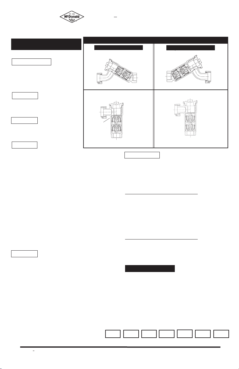
Components / Repair Parts
Standard Flow Direction
O-ring
→
Inlet
→
Bottom
cartridge
check
O-ring repair part
→
Inlet
→
→
O-ring
repair part
→
→
O-ring
→
→
→
→
Insert spacer
repair part
→
Bottom
→
check cartridge
repair part
→
Outlet
Reverse Flow Direction
O-ring
→
Inlet
→
O-ring repair part
Outlet
O-ring
repair part
→
Outlet
SPACE 8 & 9
Sizes for inlet (8) and outlet (9) connections:
1 = 1/2" 3 = 3/4" 5 = 1 1/4"
2 = 5/8" 4 = 1" 6 = 1 1/2"
Thread size of meter swivel nut:
METER THREAD METER
SIZE SIZE DESIGNATOIN
5/8 3/4" 3
5/8x3/4 1" 4
3/4 1" 4
1 1 1/4" 5
For Iron Yokes use the following
designation:
METER THREAD METER
SIZE SIZE DESIGNATOIN
5/8 - 2
5/8x3/4 - 3
3/4 - 3
1 - 4
HOW TO ORDER
UNIT REQUIRED (Example):
• Angle style valve • No test valve
• Valve size 3/4" • Outlet - FIP integral 3/4"
Meter swivel integral with
• Inlet -
saddle (5/8 x 3/4 meter)
Not all sizes or combinations are
available - contact factory.
Order Model 112-3HE43
Space 1-3
800-292-2737 • FAX 800-832-9296
Space 4
Space 5
Space 6
112
-
3
H
(Installation and test procedures on opposite side)
→
→
check
→
→
→
Space 7
E
→
→
Bottom
cartridge
→
Inlet
→
check cartridge
Space 8
→
O-ring
Outlet
→
→
Insert spacer
repair part
→
Bottom
repair part
Space 9
4
6/09
3
Page 2
A.Y. McDonald Mfg. Co.
1. Use only for residential and mobile home supply service or individual outlets.
2. The device can be installed in any position.
3. The device shall be installed in an accessible location to facilitate the removal for servicing
and testing.
4. Service lines should be thoroughly ushed before installing the device. Excessive pipe
sealant or Teon tape may foul checks. A suitable strainer should be installed upstream of the device.
5. DO NOT use Vaseline ®, plumber's grease, or any other petroleum based product on seals or o-rings.
6. Insure that device is installed in proper ow direction. Refer to ow direction arrow on body.
7. Do not over-tighten O-ring cap seal or across body cylinder to avoid distortion.
8. Any sweat ttings must be completed before installing device.
9. A pressure relief valve or expansion tank is recommended downstream of device if thermal
expansion conditions are possible.
10. Use only on cold water services. Protect from freezing.
11. Refer to pressure and temperature ratings on device tag.
INSTALLATION INSTRUCTIONS
FIELD INSPECTION AND TEST PROCEDURE
A. DIS-ASSEMBLY
1. Remove the device cap.
2. Remove the two check assemblies using care not to damage device
components.
3. Visually inspect seals, sealing surfaces, etc. for debris or damage.
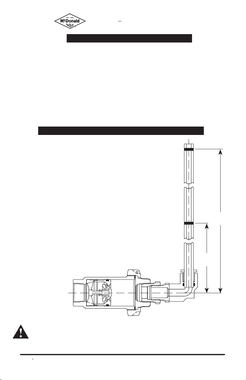
B. TESTING
1. Insert top check assembly into A.Y. McDONALD angle test kit as
shown in drawing.
2. Add water to test kit level to upper red line - 42 inches (1.5 PSIG).
3. Observe water level for up to 5 minutes until water level stabilizes.
Water level should not fall below lower red line - 28 inches (1.0 PSIG).
4. If water column falls below 28 inches the check assembly should be
cleaned and re-tested or replaced.
5. Repeat steps B1 - B4 for bottom check cartridge.
C. RE-ASSEMBLY
1. Clean and inspect device components.
2. Check cartridge O-rings should be lightly lubricated with a NSF
approved silicone lubricant.
3. Insert check assemblies into body correctly corresponding to ow
direction on the device body.
4. Insert spacer and re-assemble device cap. Do not over-tighten.
42"
28"
Contact factory for
test kit.
WARNING: Beginning January 1, 2010, it is unlawful in CALIFORNIA and VERMONT to
use any product in the installation or repair of any public water system or any plumbing in a
facility or system that provides water for human consumption if the wetted surface area of
the product has a weighted average lead content greater than 0.25%. This prohibition does
not extend to service saddles used in the state of CALIFORNIA.
A.Y. McDONALD MFG. CO. • 4800 CHAVENELLE RD. • P.O. BOX 508 • DUBUQUE, IA 52004-0508
3210-373
800-292-2737 • FAX 800-832-9296
6/09
 Loading...