

Axus YB-24S3EF4, YB-24S3ES3, YB-16S3ES3, YB-12S3EF4, YB-12S3ES3 Hardware Operation Manual
...
Yotta B SAS/SATA Series RAID Subsystem
Hardware Installation Guide
Ver. 1.0


Hardware Operation Manual
1
PPrreeffaacce
e
C
C
C
o
o
o
p
p
p
y
y
y
r
r
r
i
i
i
g
g
g
h
h
h
t
t
t
2
2
2
0
0
0
0
0
0
7
7
7
All rights Reserved - Printed in Taiwan
N
N
N
o
o
o
t
t
t
i
i
i
c
c
c
e
e
e
We make no warranties with respect to this documentation either express or implied and provide it "as
it". This includes but is not limited to any implied warranties of merchantability and fitness for a
particular purpose. The information in this document is subject t o change without notice. We assume
no responsibility for any errors that may appear in this document.
The manufacturer shall not be liable for any damage, or for the loss of information resulting from the
performance or use of the information contained he rein
T
T
T
r
r
r
a
a
a
d
d
d
e
e
e
m
m
m
a
a
a
r
r
r
k
k
k
s
s
s
Product names used herein are for identification purposes only and may be the trademarks of their
respective companies. All trademarks or registered trademarks are properties of their respective
owners.

Hardware Operation Manual
2
R
R
R
e
e
e
g
g
g
u
u
u
l
l
l
a
a
a
t
t
t
o
o
o
r
r
r
y
y
y
i
i
i
n
n
n
f
f
f
o
o
o
r
r
r
m
m
m
a
a
a
t
t
t
i
i
i
o
o
o
n
n
n
For Europe
This drive is in conformity with the EMC directive.
Federal Communications Commission (FCC) Statement
This equipment has been tested and found to comply with the limits for a Class A digital device,
pursuant to part 15 of the FCC Rules.
Those limits are designed to provide reasonable protection against harmful interference in a residential
installation. This equipment generates, uses and can radiate radio frequency energy and, if not installed
and used in accordance with the instructions, may cause harmful interference to radio communications.
However, there is no guarantee that interference will not occur in a particular installation. If this
equipment does cause harmful interference to radio or television reception, which can be determin ed
by turning the equipment off and on, the user is encouraged to try to correct the interference by one or
more of the following measures:
Reorient or relocate the receiving antennas.
Increase the separation between the equipment and receiver.
Connect the equipment into an outlet on a circlet different from that to which the receiver is connected.
Consult the dealer or an experienced radio/TV technician for help.
Warning:
A shielded-type power cord is required in order to meet FCC emission limits and also to prevent
interference to the nearby radio and television reception. It is essential that only the supplied power
cord be used.
Use only shielded cables to connect I/O devices to this equipment.
You are cautioned that changes or modifications not expressly approved by the pa rty responsible for
compliance could void your authority to operate the equipment.
Hardware Operation Manual
3
G
G
G
e
e
e
n
n
n
e
e
e
r
r
r
a
a
a
l
l
l
S
S
S
a
a
a
f
f
f
e
e
e
t
t
t
y
y
y
G
G
G
u
u
u
i
i
i
d
d
d
e
e
e
l
l
l
i
i
i
n
n
n
e
e
e
s
s
s
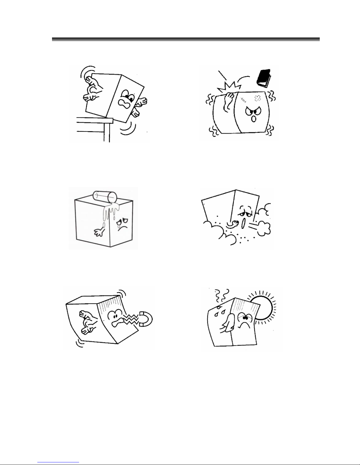
DO NOT place the RAID SYSTEM on
uneven or unstable work surfaces. Seek
servicing if the casing has been
damaged.
DO NOT place or drop objects on top of the
RAID SYSTEM and do not shove any
foreign object into it.
DO NOT expose RAID SYSTEM to
liquids, rain, or moisture.
DO NOT expose RAID SYSTEM to dirty
or dusty environments.
DO NOT expose RAID SYSTEM to
magnetic field.
DO NOT expose RAID SYSTEM to
extreme temperatures (below 5”C or above
45”C) or to direct sunlight.

Hardware Operation Manual
4
About your User’s Guide
Welcome to your Hardware Installation Guide. This manual covers everything yo u need to know in
learning how to install your RAID system. This manual also assumes that you know the basic concepts
of RAID technology. For the detail about how to configure your RAID system, please refer to the
RAID system Software Operati on manual.
Guide to conventions
Important information that users should be aware of is indicated with the following icons:
This icons indicates the existence of a potential hazard that could result in
personal injury, damage to your equipment or loss of data if the safety
instruction is not observed.
This icon indicates useful tips on getting the most from your RAID controller.
Important terms, commands and programs are put in Boldface font.
Screen text is given in screen font.

Hardware Operation Manual
5
T
T
T
a
a
a
b
b
b
l
l
l
e
e
e
o
o
o
f
f
f
C
C
C
o
o
o
n
n
n
t
t
t
e
e
e
n
n
n
t
t
t
s
s
s
PREFACE ........................................................................................................................ 1
COPYRIGHT 2007 ................................................................................................ ........1
NOTICE ....................................................................................................................... 1
TRADEMARKS .............................................................................................................1
REGULATORY INFORMATION ................................ ....................................................... 2
GENERAL SAFETY GUIDELINES................................ ...................................................3
T
T
T
A
A
A
B
B
B
L
L
L
E
E
E
O
O
O
F
F
F
C
C
C
O
O
O
N
N
N
T
T
T
E
E
E
N
N
N
T
T
T
S
S
S
................................ ................................................... 5
CHAPTER 1 .....................................................................................................................6
INTRODUCTION
................................ .................................................................6
FEATURE HIGHLIGHT ..................................................................................................6
BEFORE YOU BEGIN ................................................................ ................................ .....7
Unpacking & Checking The Equipment ................................ ............................... 7
What else you need ............................................................................................... 8
IDENTIFYING PARTS OF THE RAID SYSTEM ............................................................... 9
Front View ................................ ................................ ................................ ............9
Rear View ................................................................ ................................ ...........12
SPACE REQUIREMENT ................................ ................................ ............................... 18
SYSTEM CONNECTION ................................ ................................ ............................... 18
INSTALL HARD DISKS ................................................................................................ 19
CHAPTER 2 ...................................................................................................................21
H
H
H
A
A
A
R
R
R
D
D
D
W
W
W
A
A
A
R
R
R
E
E
E
I
I
I
N
N
N
S
S
S
T
T
T
A
A
A
L
L
L
L
L
L
A
A
A
T
T
T
I
I
I
O
O
O
N
N
N
................................ ................................ 21
REPLACE THE CONTROLLER................................ ................................ ...................... 21
REPLACING / UPGRADING DDRII SDRAM.............................................................. 24
DDRII SDRAM DIMM specifications: ................................ .............................. 24
Installing memory module ................................ ................................ .................. 24
HOT SWAPPING TO REPLACE T HE FAN MODULE ................................ ....................... 26
HOT SWAPPING TO REPLACE T HE POWER MODULE...................................................28
TURNING ON FOR THE FIRST TIME ................................ ................................ .............29
TURNING OFF ................................................................ ................................ ............29
RESTARTING ................................ ................................ .............................................29
APPENDIX A ................................ .................................................................................30
C
C
C
O
O
O
N
N
N
N
N
N
E
E
E
C
C
C
T
T
T
O
O
O
R
R
R
S
S
S
................................ ....................................................................30
APPENDIX B ................................ .................................................................................32
BATTERY BACKUPM
ODUL
E (BBM)
................................ ......................................32
APPENDIX C ................................ .................................................................................35
S
S
S
P
P
P
E
E
E
C
C
C
I
I
I
F
F
F
I
I
I
C
C
C
A
A
A
T
T
T
I
I
I
O
O
O
N
N
N
S
S
S
................................ ............................................................. 35

Hardware Operation Manual
6
CChhaapptteerr1
1
IInnttrroodduuccttiioon
n
This chapter introduces the features and capabilities of RAID SYSTEM.
You will find:
A
A
A
f
f
f
u
u
u
l
l
l
l
l
l
i
i
i
n
n
n
t
t
t
r
r
r
o
o
o
d
d
d
u
u
u
c
c
c
t
t
t
i
i
i
o
o
o
n
n
n
t
t
t
o
o
o
y
y
y
o
o
o
u
u
u
r
r
r
R
R
R
A
A
A
I
I
I
D
D
D
S
S
S
Y
Y
Y
S
S
S
T
T
T
E
E
E
M
M
M
D
D
D
e
e
e
t
t
t
a
a
a
i
i
i
l
l
l
s
s
s
o
o
o
f
f
f
k
k
k
e
e
e
y
y
y
f
f
f
e
e
e
a
a
a
t
t
t
u
u
u
r
r
r
e
e
e
s
s
s
a
a
a
n
n
n
d
d
d
s
s
s
u
u
u
p
p
p
p
p
p
l
l
l
i
i
i
e
e
e
d
d
d
a
a
a
c
c
c
c
c
c
e
e
e
s
s
s
s
s
s
o
o
o
r
r
r
i
i
i
e
e
e
s
s
s
A
A
A
c
c
c
h
h
h
e
e
e
c
c
c
k
k
k
l
l
l
i
i
i
s
s
s
t
t
t
o
o
o
f
f
f
p
p
p
a
a
a
c
c
c
k
k
k
a
a
a
g
g
g
e
e
e
c
c
c
o
o
o
n
n
n
t
t
t
e
e
e
n
n
n
t
t
t
s
s
s
A
A
A
c
c
c
h
h
h
e
e
e
c
c
c
k
k
k
l
l
l
i
i
i
s
s
s
t
t
t
o
o
o
f
f
f
w
w
w
h
h
h
a
a
a
t
t
t
e
e
e
l
l
l
s
s
s
e
e
e
y
y
y
o
o
o
u
u
u
n
n
n
e
e
e
e
e
e
d
d
d
t
t
t
o
o
o
s
s
s
t
t
t
a
a
a
r
r
r
t
t
t
i
i
i
n
n
n
s
s
s
t
t
t
a
a
a
l
l
l
l
l
l
a
a
a
t
t
t
i
i
i
o
o
o
n
n
n
F
F
F
e
e
e
a
a
a
t
t
t
u
u
u
r
r
r
e
e
e
H
H
H
i
i
i
g
g
g
h
h
h
l
l
l
i
i
i
g
g
g
h
h
h
t
t
t
The RAID SYSTEM is designed to meet today’s high volume, performance storage requirements from
rapidly changing business environment. It provides a maximum data protection and exceptional
performance in a storage subsystem. Target usa ge ranges are set from small business to departmental and
corporate server needs. The RAID SYSTEM is designed for easy integration, smooth data expansion and
server migration.
The RAID SYSTEM supports the following features:
Intel 800Mhz IOP341 64bit storage processor
Support cache memory size up to 2GB in DDRII-533/667 DIMM type with ECC embedded
Support 12/16/24 SAS/SATAII disk channels.
Dual 4Gb FC host interface support by FC to SAS
Dual mini SAS 4 x 3 SAS Ports support by SAS to SAS
Support RAID level 0, 1, 1+0, 3, 5, 6, 30, 50, 60 and JBOD
Redundant and Hot Swappable Fan, Power and Drives.
Hot Swap, Hot Spare and Automatic Drive Rebuild Supported.
Configuration and environmental information is accessible either via the control panel or Serial Port or
10/100 Ethernet LAN port.
E-mail event notification.
Load sharing hot swappable redundant power system with PFC function
Host System independent.
Operating System independent.

Hardware Operation Manual
7
B
B
B
e
e
e
f
f
f
o
o
o
r
r
r
e
e
e
y
y
y
o
o
o
u
u
u
b
b
b
e
e
e
g
g
g
i
i
i
n
n
n
Unpacking & Checking The Equipment
Before unpacking the RAID SYSTEM, prepare a clean, stable surface to put on the
contents of your RAID SYSTEM shipping container. Altogether, you should find the
following items in the package :
Fibre to SAS RAID system
RAID System x1
RAID system Hardware Installation Guide (CD media )
RAID system Software Operation Manual (CD media )
RS232 cable x1
Power Cord x 2 ( 24Bay x 3)
FAN x 1
HDD tray x 1
Mounting screws (bag) ×1
SAS to SAS RAID system
RAID System x1
RAID system Hardware Installation Guide (CD media )
RAID system Software Operation Manual (CD media )
RS232 cable x1
Mini SAS to Mini SAS Cable x 1
Power Cord x 2 ( 24Bay x 3)
FAN x 1
HDD tray x 1
Mounting screws (bag) ×1
To avoid the unmatched cable between the Fibre HBA in the Host and
Fibre-SAS RAID SYSTEM, Fibre-SAS RAID system doesn’t include the Fibre
interface with the standard configuration. There are many different kinds of
Fibre connectors on varied of Fibre HBAs.

Hardware Operation Manual
8
What else you need
Hard disk drives (different RAID levels requires different numbers of HDDs ). Refer to
Software Operation manual for more detail information.
Host computer with Fibre interface (Fibre-SAS RAID SYSTEM)
Host computer with SAS interface (SAS-SAS RAID SYSTEM)
Static grounding strap or electrostatic discharge (ESD) safe work area
Dedicated terminal or PC with third party communication software that supports ANSI
terminal emulation (required for viewing Monitor Utility)
The hard drives in a RAID system should match in size and speed. All drives in
any array should be identical models with the same firmware versions. RAID
system can use any size drive, however the smallest drive will determine the
size of the array.
There's no set formula to determine how much cache memory to use, but as a
general rule, a workstation, with mostly very large fi les, such as for audio or
video editing and playback, graphics or CAD files, can benefit from a large
cache. File servers, with multiple random access of varying file size, generally
have little or no performance improvement with additional cache.
RAID system do not require the installation of different drivers for use with
different operating systems. RAID system is independent and transparent to
the host operating system.
Hardware Operation Manual
9
I
I
I
d
d
d
e
e
e
n
n
n
t
t
t
i
i
i
f
f
f
y
y
y
i
i
i
n
n
n
g
g
g
P
P
P
a
a
a
r
r
r
t
t
t
s
s
s
O
O
O
f
f
f
T
T
T
h
h
h
e
e
e
R
R
R
A
A
A
I
I
I
D
D
D
s
s
s
y
y
y
s
s
s
t
t
t
e
e
e
m
m
m
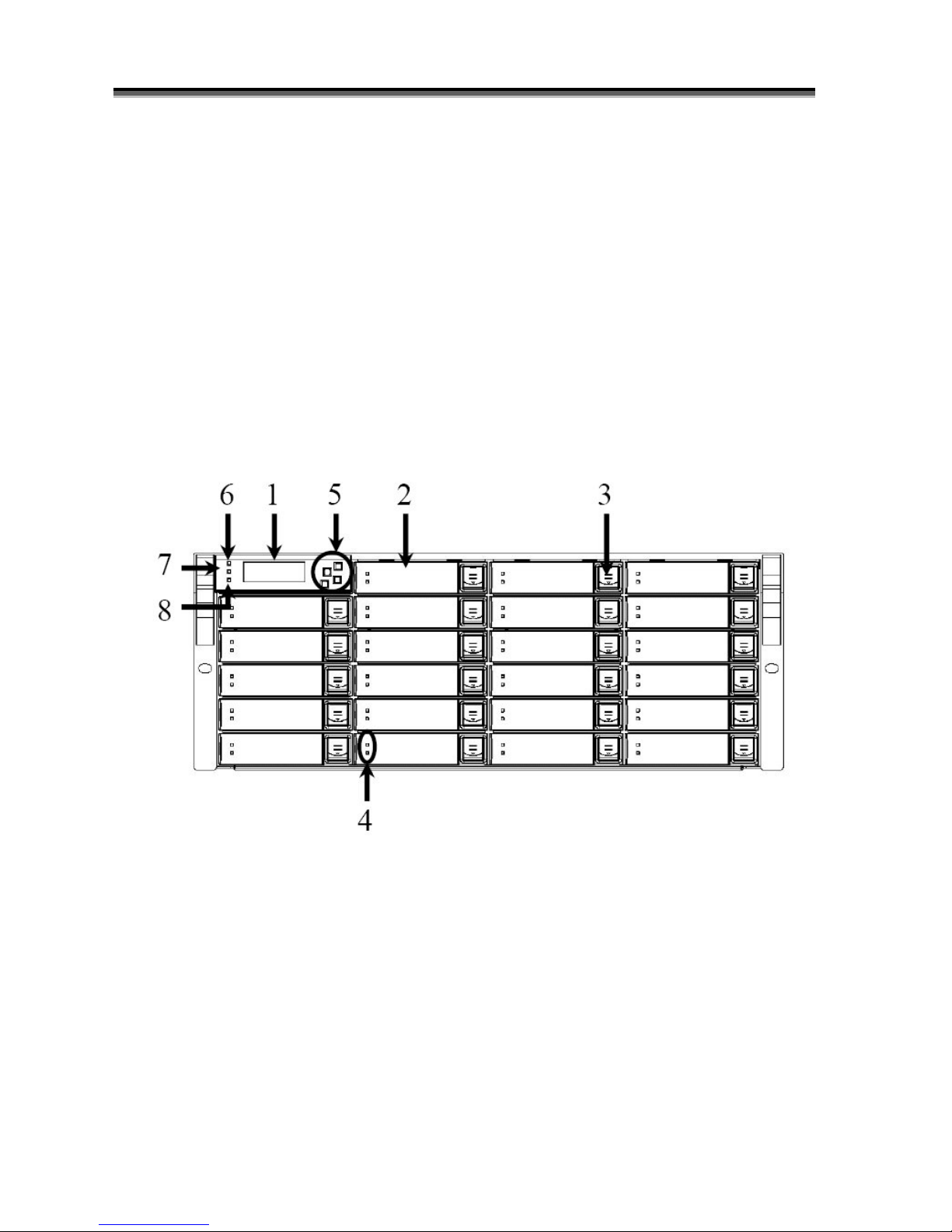
The illustrations below identify the various parts of the RAID SYSTEM. Get yourself to familiar with
these terms as it will help you when you read further in the following sections :
Front View
YB-24S3EF4 / YB-24S3ES3

Hardware Operation Manual
10
YB-16S3EF4 / YB-16S3ES3
YB-12S3EF4 / YB-12S3ES3

Hardware Operation Manual
11
1. LCD Display Panel.
The front panel LCD continuously displays the status of the RAID SYSTEM. The following is an example
of the RAID SYSTEM
2. Cartridge Handle
3. Lock & Release-Button
4. HDD status LED Indicator
LED
Colors
Indicate
Blue
or Green
HDD On Line
Blue +
Blink
or Amber
HDD Access
?
Red
HDD Error
5. Function keys. ( ENT , ESC, Scroll up , Scroll Down )
Keys
Descriptions
Up Arrow
To scroll upward through the menu items
Down Arrow
To scroll downward through the menu items
(ENT ) Enter
To confirm a selected item
(ESC) ESC
To exit a sub-menu and return to previous menu.
6.
Power On Indicator ( Blue or Green).
7.
Power Fail Indicator (Red)
8.
A
Host System Access Indicator ( Blue + blink or Yellow).

Hardware Operation Manual
12
Rear View
YB-24S3EF4
YB-24S3ES3

Hardware Operation Manual
13
Fibre-SAS RAID SYSTEM: 1. FC CH 1
2. FC CH 0
SAS-SAS RAID SYSTEM: 1. SAS CH 1
2. SAS CH 0
3. SAS Expand Port
4. Console
5. Terminal
6. LAN port
7. Controller Box 1
8. Controller Box 2 (Reserve d)
9. FAN failure indicator (Rear / Front)
10. FAN Module /FAN Module 1
11. FAN Module /FAN Module 1 latch
12. Power Switch
13. FAN failure indicator (Rear / Front)
14. FAN Module 2
15. FAN Module 2 latch
16. AC inlet 1 & Ltch
17. Power Module 1
18. AC inlet 2 & Latch
19. Power Module 2
20. AC inlet 3 & Latch
21. Power Module 3

Hardware Operation Manual
14
YB-16S3EF4
YB-16S3ES3

Hardware Operation Manual
15
Fibre-SAS RAID SYSTEM: 1. FC CH 1
2. FC CH 0
SAS-SAS RAID SYSTEM: 1. SAS CH 1
2. SAS CH 0
3. SAS Expand Port
4. Console
5. Terminal
6. LAN port
7. Controller Box 1
8. Controller Box 2 (Reserved)
9. FAN failure indicator (Rear / Front)
10. FAN Module /FAN Module 1
11. FAN Module /FAN Module 1 latch
12. Power Switch
13. FAN failure indicator (Rear / Front)
14. FAN Module 2
15. FAN Module 2 latch
16. AC inlet 1 & Ltch
17. Power Module 1
18. AC inlet 2 & Latch
19. Power Module 2

Hardware Operation Manual
16
YB-12S3EF4
YB-12S3ES3

Hardware Operation Manual
17
1. LAN port
2. Terminal
3. Console
4. SAS Expand Port
Fibre-SAS RAID SYSTEM: 5. FC CH 1
6. FC CH 0
SAS-SAS RAID SYSTEM: 5. SAS CH 1
6. SAS CH 0
7. FAN Module /FAN Module 1 latch
8. FAN Module /FAN Module 1
9. FAN failure indicator (Rear / Front)
10. Power Module 1
11. Power Module 2
12. AC inlet 1 & Latch
13. AC inlet 2 & Latch
14. Power Switch

Hardware Operation Manual
18
S
S
S
p
p
p
a
a
a
c
c
c
e
e
e
R
R
R
e
e
e
q
q
q
u
u
u
i
i
i
r
r
r
e
e
e
m
m
m
e
e
e
n
n
n
t
t
t
When selecting a location for your system, be sure to allow an adequate space. The system has vents
around it which will require a minimum of 3 inches of unobstructed space for airflow. Openings in the
equipment should be blocked, or there may be a n issue of reliability problems with your syst em. A system
product should never be place around a radiator or heat register.
S
S
S
y
y
y
s
s
s
t
t
t
e
e
e
m
m
m
C
C
C
o
o
o
n
n
n
n
n
n
e
e
e
c
c
c
t
t
t
i
i
i
o
o
o
n
n
n
Connect all cables and power cord as shown below :
Cable
Raid System
Device
Purpose
RS-232 Cable
Terminal Port
ANSI Terminal or a PC with
Terminal emulator.
Configuration Utility
RS-232 Cable
Console Port
ANSI Terminal or a PC with
Terminal emulator.
Debug port, to check and
monitoring all of status of
RAID subsystem.
Fibre cable /
Mini SAS Cable
Primary FC-AL / SAS
Secondly FC-AL / SAS
FC-AL / SAS HBA of Host
computer
Host interface between
RAID and Host computer
Power Cord
Power inlet
A/C power outlet
A/C power input
RJ 45 Cable
Ethernet Port
Switch or HUB
Connect to Internet.
Mini SAS Cable
SAS Expander Port
Raid System
Connect to SAS Expander
Make sure that all the devices are powered off before connecting or removing
cables to prevent power spikes which can damage technical components.

Hardware Operation Manual
19
I
I
I
n
n
n
s
s
s
t
t
t
a
a
a
l
l
l
l
l
l
h
h
h
a
a
a
r
r
r
d
d
d
d
d
d
i
i
i
s
s
s
k
k
k
s
s
s
The RAID SYSTEM includes 12/16/24 ( depending on your models) removable disk cartridges. The
following sections describe how to install disks into RAID SYSTEM subsystems.
Remove Cartridges
We designed the lock/unlock mechanism on a
same button and called EzSecurLock . No need a
key but with security .
How to remove Cartridges?
1: Push the button inward
2: While holding in the button, then slide down
3: The HDD door will be opened automatically.

Hardware Operation Manual
20
Install HDDs.
1) Put HDD into the Cartridge.
2) Align 4 screws holes on both HDD &
Cartridge.
3) Fasten all 4 screws to mount HDD in the
cartridge and make sure the HDD is properly
tightened.
Install Cartridges
Reversed the procedures of “Remove cartridges”
to install cartridges back to RAID system .

Hardware Operation Manual
21
CChhaapptteerr2
2
H
H
H
a
a
a
r
r
r
d
d
d
w
w
w
a
a
a
r
r
r
e
e
e
I
I
I
n
n
n
s
s
s
t
t
t
a
a
a
l
l
l
l
l
l
a
a
a
t
t
t
i
i
i
o
o
o
n
n
n
This chapter presents:
I
I
I
n
n
n
s
s
s
t
t
t
r
r
r
u
u
u
c
c
c
t
t
t
i
i
i
o
o
o
n
n
n
s
s
s
o
o
o
n
n
n
r
r
r
e
e
e
p
p
p
l
l
l
a
a
a
c
c
c
i
i
i
n
n
n
g
g
g
c
c
c
o
o
o
m
m
m
p
p
p
o
o
o
n
n
n
e
e
e
n
n
n
t
t
t
s
s
s
I
I
I
n
n
n
s
s
s
t
t
t
r
r
r
u
u
u
c
c
c
t
t
t
i
i
i
o
o
o
n
n
n
s
s
s
o
o
o
n
n
n
r
r
r
e
e
e
p
p
p
l
l
l
a
a
a
c
c
c
i
i
i
n
n
n
g
g
g
t
t
t
h
h
h
e
e
e
h
h
h
o
o
o
t
t
t
s
s
s
w
w
w
a
a
a
p
p
p
p
p
p
a
a
a
b
b
b
l
l
l
e
e
e
c
c
c
o
o
o
m
m
m
p
p
p
o
o
o
n
n
n
e
e
e
n
n
n
t
t
t
s
s
s
I
I
I
n
n
n
s
s
s
t
t
t
r
r
r
u
u
u
c
c
c
t
t
t
i
i
i
o
o
o
n
n
n
s
s
s
o
o
o
n
n
n
h
h
h
o
o
o
w
w
w
t
t
t
o
o
o
i
i
i
n
n
n
s
s
s
t
t
t
a
a
a
l
l
l
l
l
l
a
a
a
n
n
n
d
d
d
u
u
u
p
p
p
g
g
g
r
r
r
a
a
a
d
d
d
e
e
e
D
D
D
R
R
R
A
A
A
M
M
M
R
R
R
e
e
e
p
p
p
l
l
l
a
a
a
c
c
c
e
e
e
t
t
t
h
h
h
e
e
e
C
C
C
o
o
o
n
n
n
t
t
t
r
r
r
o
o
o
l
l
l
l
l
l
e
e
e
r
r
r
Read the replacing notices earlier in this chapter before proceeding with
replacement.
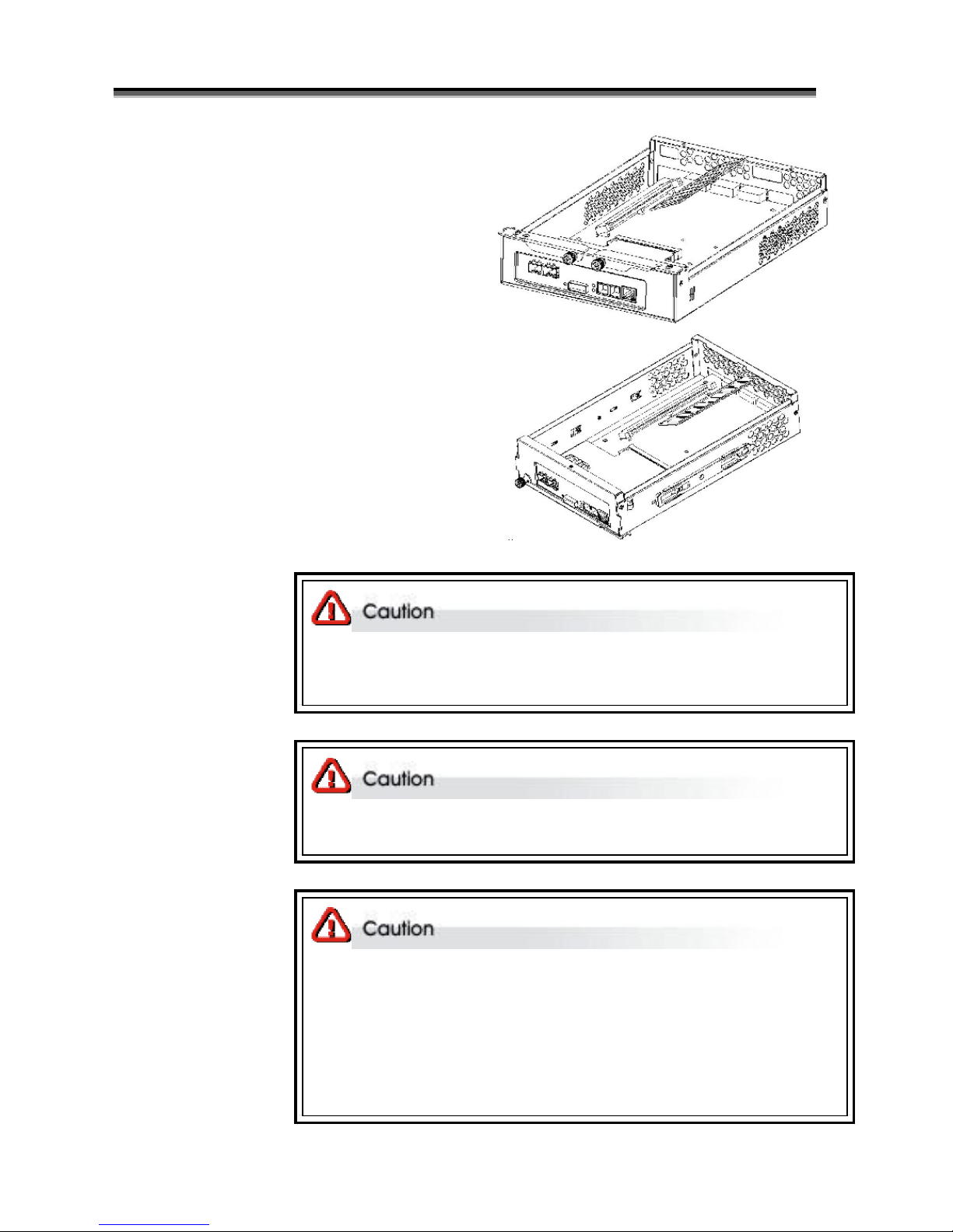
This section provides instructions for the removal and insta llation of the RAID controller components
indicated in the figure below. This section is for the reference of engineers. End users should not need to
replace or remove components.

Hardware Operation Manual
22
Removing the controller from YB-12/YB-16/YB-24 series
YB-24S3EF4 / YB-24S3ES3
YB-16S3EF4 / YB-16S3ES3
Installing the controller into YB-16S3EF4 (YB-24S3EF4) / YB-16S3ES3 (YB-24S3ES3)
Reverse the procedures as above to install the controller into YB-16S3EF4 (YB-24S3EF4).
/ YB-16S3ES3 (YB-24S3ES3)
1:
1-1.) Disconnect the host
cables
1-2.) Turn anti-clock wise to
release the thumb screw.
1-3.) Use the eject kit to remove
controller board.
2:
2-1.) Slide it back and lifting off

Hardware Operation Manual
23
YB-12S3EF4 / YB-12S3ES3
Installing the controller into YB-12S3EF4 / YB-12S3ES3
Reverse the procedures as above to install the controller into YB-12S3EF4 / YB-12S3ES3
1:
1-1.) Disconnect the host
cables
1-2.) Turn anti-clock wise to
release the thumb screw.
1-3.) Use the eject kit to remove
controller board.
2:
2-1.) Slide it back and lifting off
Hardware Operation Manual
24
R
R
R
e
e
e
p
p
p
l
l
l
a
a
a
c
c
c
i
i
i
n
n
n
g
g
g
/
/
/
U
U
U
p
p
p
g
g
g
r
r
r
a
a
a
d
d
d
i
i
i
n
n
n
g
g
g
D
D
D
D
D
D
R
R
R
I
I
I
I
I
I
S
S
S
D
D
D
R
R
R
A
A
A
M
M
M
Read the pre-installation notices earlier in this chapter before proceeding with
installation.
RAID SYSTEM is normally supplied with 512MB DDRII-533/667 SDRAM installed.
There's no set formula to determine how much cache memory to use, but as a
general rule, a workstation, with mostly very large files, such as for audio or
video editing and playback, graphics or CAD files, can benefit from a large
cache. File servers, with multiple random access of varying file size, generally
have little or no performance improvement with additional cache.
Memory serves as the data buffer to increase the CPU utilization rate and minimize the overhead of data
accessing , thus, improves the overall performance. YB-12S3/16S3/24S3 supports up to 2GB DDRII-
533/667 DIMM type with ECC type memories .
The DDR memory socket is used 240-pin DDR2 DIMM socket . Use 25 degree DDR2 DIMM socket
DDRII SDRAM DIMM specifications:
Memory
Memory type
240-pin DDR2 DIMM x 1
Memory socket type
25 degree DDR2 DIMM socket
Memory size
Up to 2GB with 64-bit DDR533/667 with ECC
Installing memory module
To install a DDRII SDRAM ensure the system is power off and disconnected. Then:
Hardware Operation Manual
25
1: Removing the controller module from Raid system.
2: Open the cover of controller module .
3. Insert a memory module into the memory socket .
4.Close the cover of controller module .
Before starting any kind of hardware installation, please ensure that all powe r
switches have been turned off and all power cords disconnected to prevent
personal injury and damage to the hardware
Use screws provided with RAID system only. Longer or shorter screws may
cause electric shorting or un -proper installed.
Static electricity can damage electronic components. To guard against such
damage:
Work in a static-free environment
Wear a grounded anti -static wrist strap
Store uninstalled components in anti -static bags
Handle PCBs by their edges and a void touching chips and connectors.

Hardware Operation Manual
26
H
H
H
o
o
o
t
t
t
S
S
S
w
w
w
a
a
a
p
p
p
p
p
p
i
i
i
n
n
n
g
g
g
t
t
t
o
o
o
r
r
r
e
e
e
p
p
p
l
l
l
a
a
a
c
c
c
e
e
e
t
t
t
h
h
h
e
e
e
F
F
F
a
a
a
n
n
n
M
M
M
o
o
o
d
d
d
u
u
u
l
l
l
e
e
e
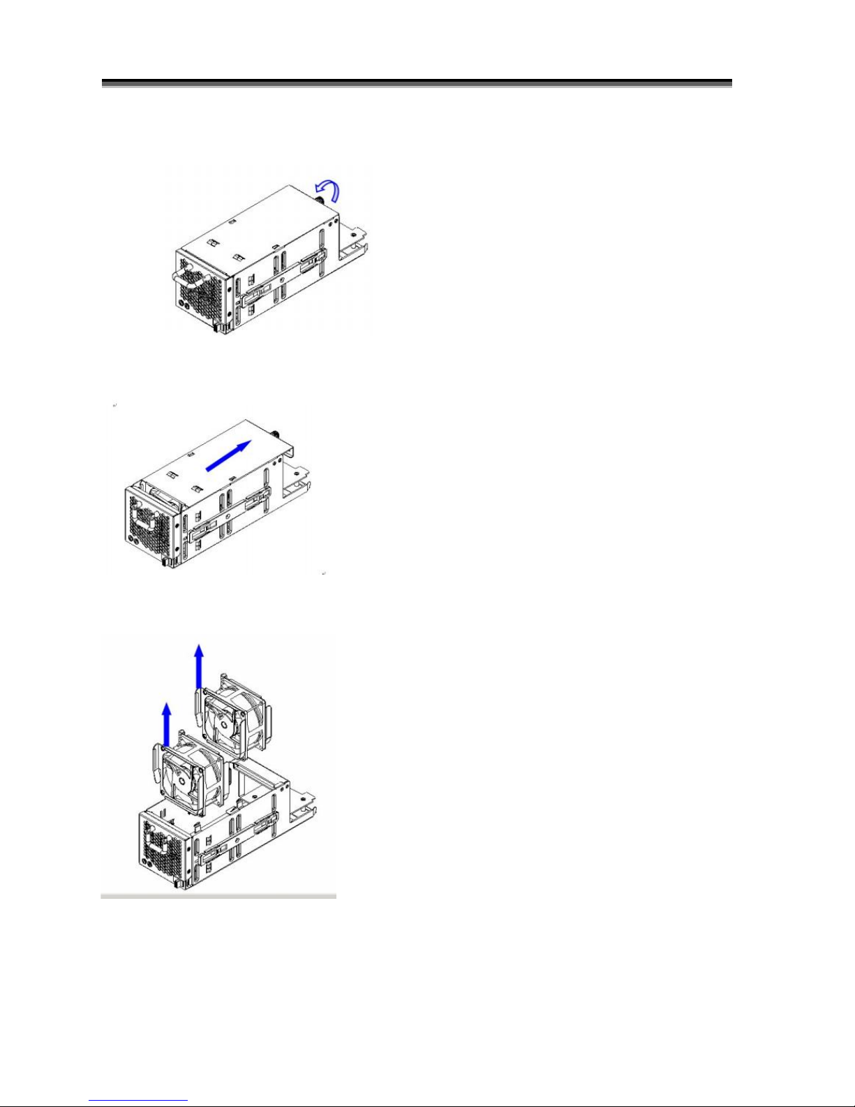
This section provides instructions for the removal and installation of the Fan Module indicated in the
figure below.
YB-16S3 & YB-24S3
YB-12S3
Removing the Fan Module from
RAID system
Remove the Fan modules by
pushing the latch to release the lock
of module then slide it back and
lifting off.
Installing the Fan module into
RAID system :
Insert a Fan module into system ,
the latch will lock the Fan module
automatically.
Hardware Operation Manual
27
Replacing Fan in a Fan Module:
Step 1: Turn anti-clock wise to release the thumb screw.
Step 2: slide the cover to blue arrow direction .
Step 3: Remove the cover of Fan module and lift the Fans .
Hardware Operation Manual
28
H
H
H
o
o
o
t
t
t
S
S
S
w
w
w
a
a
a
p
p
p
p
p
p
i
i
i
n
n
n
g
g
g
t
t
t
o
o
o
r
r
r
e
e
e
p
p
p
l
l
l
a
a
a
c
c
c
e
e
e
t
t
t
h
h
h
e
e
e
P
P
P
o
o
o
w
w
w
e
e
e
r
r
r
M
M
M
o
o
o
d
d
d
u
u
u
l
l
l
e
e
e
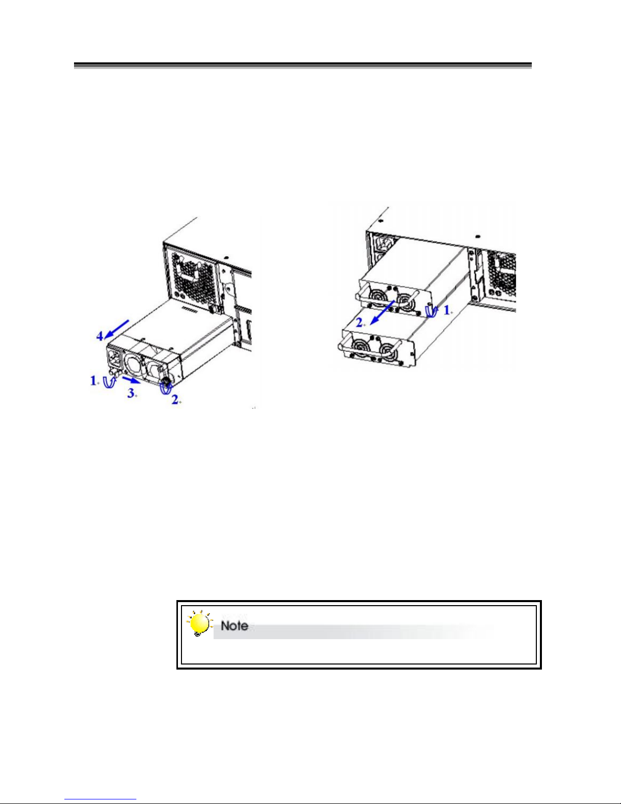
This section provides instructions for the removal and installation o f the Power Module indicated in
the figure below.
Removing the Power Module from
RAID system YB-16/24S3 :
Removing the Power Module from
RAID system Y2-12S3 :
Step1&2: Unscrew the fastener.
Step3:Release the latch and hold it at
unlock-position.
Step4:Slide it back and lifting off.
Step1: Unscrew the fastener
Step 2: Slide it back and lifting off.
Installing the Power module into RAID
system :
Insert a Power module then fasten the
screw.
The Power indicator will turn bright “Green” to indicate it has powered on

Hardware Operation Manual
29
T
T
T
u
u
u
r
r
r
n
n
n
i
i
i
n
n
n
g
g
g
o
o
o
n
n
n
f
f
f
o
o
o
r
r
r
t
t
t
h
h
h
e
e
e
f
f
f
i
i
i
r
r
r
s
s
s
t
t
t
t
t
t
i
i
i
m
m
m
e
e
e
When cabling is complete d, RAID SYSTEM can be turned on. This s hould be done in the following
order:
1. First turn on the power switch of RAID SYSTEM.
2. Then power on and boot the host computer(s)
When RAID SYSTEM is running, you are ready to configure one or more RAID arrays. You have the
following options:
1. Turn to Chapter 2 of “Software Operation Manual” to perform a quick setup of a single RAID array
using the control panel.
2. Turn to Chapter 3 of “Software Operation Manual” to access the Monitor Utility. Once the Monitor
Utility is accessed, you can perform a Quick Setup (Chapter 2) or complete configuration (Chapter 4)
with either the control panel or Monitor Utility.
3. Turn to Chapter 4 of “Software Operation Manual” to perform a full configuration using the control
panel.
T
T
T
u
u
u
r
r
r
n
n
n
i
i
i
n
n
n
g
g
g
o
o
o
f
f
f
f
f
f
When turning off RAID SYSTEM, users are advised to first shut down the server, then power off
RAID SYSTEM.
R
R
R
e
e
e
s
s
s
t
t
t
a
a
a
r
r
r
t
t
t
i
i
i
n
n
n
g
g
g
When restarting RAID SYSTEM, users are advised to first restart the server, then power on RAID
SYSTEM.

Hardware Operation Manual
30
Pin#
Signal Name
1
TX+
2
TX-
3
RX+
4
NC
5
NC
6
RX-
7
NC
8
NC
AAppppeennddiixxA
A
C
C
C
o
o
o
n
n
n
n
n
n
e
e
e
c
c
c
t
t
t
o
o
o
r
r
r
s
s
s
Ethernet RJ-45 Connector
1
8
Fibre SFP
Pin#
Signal Name
1
V
EFT
2
T
FAULT
3
T
DIS
4
MOD_DEF(2)
5
MOD_DEF(1)
6
MOD_DEF(0)
7Rat
e Selec
t
8
LOS
9
V
EER
10
V
EER
11
V
EER
12
RD-
13
RD+
14
V
EER
15
V
CCR
16
V
CCT
17
V
EET

Hardware Operation Manual
31
Pin#
Signal
Pin#
Signal
1NC6
NC
2
GND
3
RX
4
TX
5
CTS
RJ-11 RS-232

Hardware Operation Manual
32
AAppppeennddiixxB
B
Battery Back
upModul
e (BBM)
The external RAID controller operates using cache memory .The battery Backup Module is
an add-on module that provides power to the external RAID controller cache memory in
the event of a power failure. The Battery Backup Module monitors the write back cache
on the external RAID controller, and provides power
to the cache memory if it contains data not yet written to the hard drives when power failure
occurs.
BBM Components
Battery Connector
BBM Specifications
Mechanical
Module Dimension (W x H x D) : 50 x 5 x 147 mm
BBM Connector
3 x Pins Connector
Input Voltage
+3.6 VDC
On Board Battery Capacity
3000MAH (3*1000MA H)

Hardware Operation Manual
33
Installation
Make sure all power to the system is disconnected.
Remove the controller box.
Remove the memor y.
Exchange 4 screws to 4 holding pole, as bellow :
Install the BBM and fasten 4 screws.
Plug in the BBM’s connector into J6 of Controlle r.

Hardware Operation Manual
34
Battery Backup Capacity
Battery backup capacity is defined as the maximum duration of a power failure for which
data in the cache memory can be maintained by the battery. The BBM’s backup capacity
varied with the memory chips that installed on the external RAID controller..
Capacity
Memory Type
Battery Backup duration(Hours)
512MB Memory
Normal
160
1GB Memory
Normal
105
Operation
Battery conditioning is automatic. There are no manual procedures for battery
conditioning or preconditionin g to be performed by the use r.
Battery bad a tendency to “remember” its capacity. In order to make sure of all the
capacity of your battery cells, allow the battery cell to be fully charged when installed
for the first time. The first time charge of battery cells takes about 24 hours to
complete.
Removing the Battery Backup Module
The battery module will need to be removed for one of the following reason:
Disconnect battery module if there is a long storage period before deployment
The LI-ION battery will no longer accept a charge properl y.

Hardware Operation Manual
35
AAppppeennddiixxC
C
S
S
S
p
p
p
e
e
e
c
c
c
i
i
i
f
f
f
i
i
i
c
c
c
a
a
a
t
t
t
i
i
i
o
o
o
n
n
n
s
s
s
YB-24S3EF4/YB-16S3EF4/YB-12S3EF4
YB-24S3EF4
YB-16S3EF4
YB-12S3EF4
Model
FCFCFC
RAID Engine
Intel Xscal i81341 @800Mhz
RAID Levels
0, 1,1+0, 3, 5 , 6, 30, 50 ,60 & JBOD
Cache Support
(Write back)
Up to 2GBytes with ECC240pins DDR2 SDRAM Memory
System Type
Rack mountable
Host Interface
Dual loops 4Gb Fibre Channels, Standard SFP connectors
Host Transfer Rate
4Gb/ Sec per loop
Disk Interface
SAS 3.0 Gbps
Disk Channel
Sixteen SAS 3.0 Gb Disk Channels
LCD Display
2 Lines by 16 Characters
Hot Swap and
redundant
Yes (Power Supply, Drive and Fan).
Hot Spare
Yes (Drive).
Battery Back-Up
Module
Optional, Support up to 72hrs battery back -up time (N.A.)
Array Management
Support
Yes.
Automatic Bad-Sector
& Error Recovery
Yes.
Automatic Drive
Rebuilds
Yes. Automatic Data rebuilds.
Remote Terminal
Configuration
Yes. Through Network port .or Terminal port
Operating Systems
O/S Independent and Transparent
Power Supply
460+460+460 watts
Redundancy high quality power
system, Three 460 watts
module with PFC function.
Load sharing type and
cable-less design with
Redundancy Dual Power inlet
460+460 watts Redundancy
high quality power system, two
460 watts module with PFC
function. Load sharing type and
cable-less design with
Redundancy Dual Power inle t
375+375 watts Redundancy
high quality power system,
three 375 watts module with
PFC function. Load sharing
type and cableless design with
Redundancy Dual Power inlet
Electrical
AC Voltage 100-240 VAC
Ac Frequency 47-63Hz
Temperature
Operating Temperature : 5 to 35 degree C.
Non Operating Temperature : -40 to 60 degree C.
Relative Humidity
20% to 80% non-condensing
Dimensions
447mm(W)*550mm(D)*4U(H)
447mm(W)*496mm(D)*3U(H)
447mm(W)*496mm(D)*2U(H)

Hardware Operation Manual
36
YB-24S3ES3/YB-16S3ES3/YB-12S3ES3
YB-24S3ES3
YB-16S3ES3
YB-12S3ES3
Model
SAS
SAS
SAS
RAID Engine
Intel Xscal i81341 @800Mhz
RAID Levels
0, 1,1+0, 3, 5 , 6, 30, 50 ,60 & JBOD
Cache Support
(Write back)
Up to 2GBytes with ECC240pins DDR2 SDRAM Memory
System Type
Rack mountable
Host Interface
Dual 4 x 3 SAS Ports, Standard Mini SAS connectors
Host Transfer Rate
3Gb/ Sec per port
Disk Interface
SAS 3.0 Gbps
Disk Channel
Sixteen SAS 3.0 Gb Disk Channels
LCD Display
2 Lines by 16 Characters
Hot Swap and
redundant
Yes (Power Supply, Drive and Fan).
Hot Spare
Yes (Drive).
Battery Back-Up
Module
Optional, Support up to 72hrs battery back -up time (N.A.)
Array Management
Support
Yes.
Automatic Bad-Sector
& Error Recovery
Yes.
Automatic Drive
Rebuilds
Yes. Automatic Data rebuilds.
Remote Terminal
Configuration
Yes. Through Network port .or Terminal port
Operating Systems
O/S Independent and Transparent
Power Supply
460+460+460 watts
Redundancy high quality power
system, Three 460 watts
module with PFC function.
Load sharing type and
cable-less design with
Redundancy Dual Power inlet
460+460 watts Redundancy
high quality power system, two
460 watts module with PFC
function. Load sharing type and
cable-less design with
Redundancy Dual Power inle t
375+375 watts Redundancy
high quality power system,
three 375 watts module with
PFC function. Load sharing
type and cableless design with
Redundancy Dual Power inlet
Electrical
AC Voltage 100-240 VAC
Ac Frequency 47-63Hz
Temperature
Operating Temperature : 5 to 35 degree C.
Non Operating Temperature : -40 to 60 degree C.
Relative Humidity
20% to 80% non-condensing
Dimensions
447mm(W)*550mm(D)*4U(H)
447mm(W)*496mm(D)*3U(H)
447mm(W)*496mm(D)*2U(H)
*Specification subject to change without notice, all trademarks or
registered trademarks are properties of their respective owners.
 Loading...