

Page 1
Ethernet Packet Generator
USER GUIDE
APG-UG-V2-1 1 8 February 2018
Ethernet Packet Generator
USER GUIDE
Version 2.1
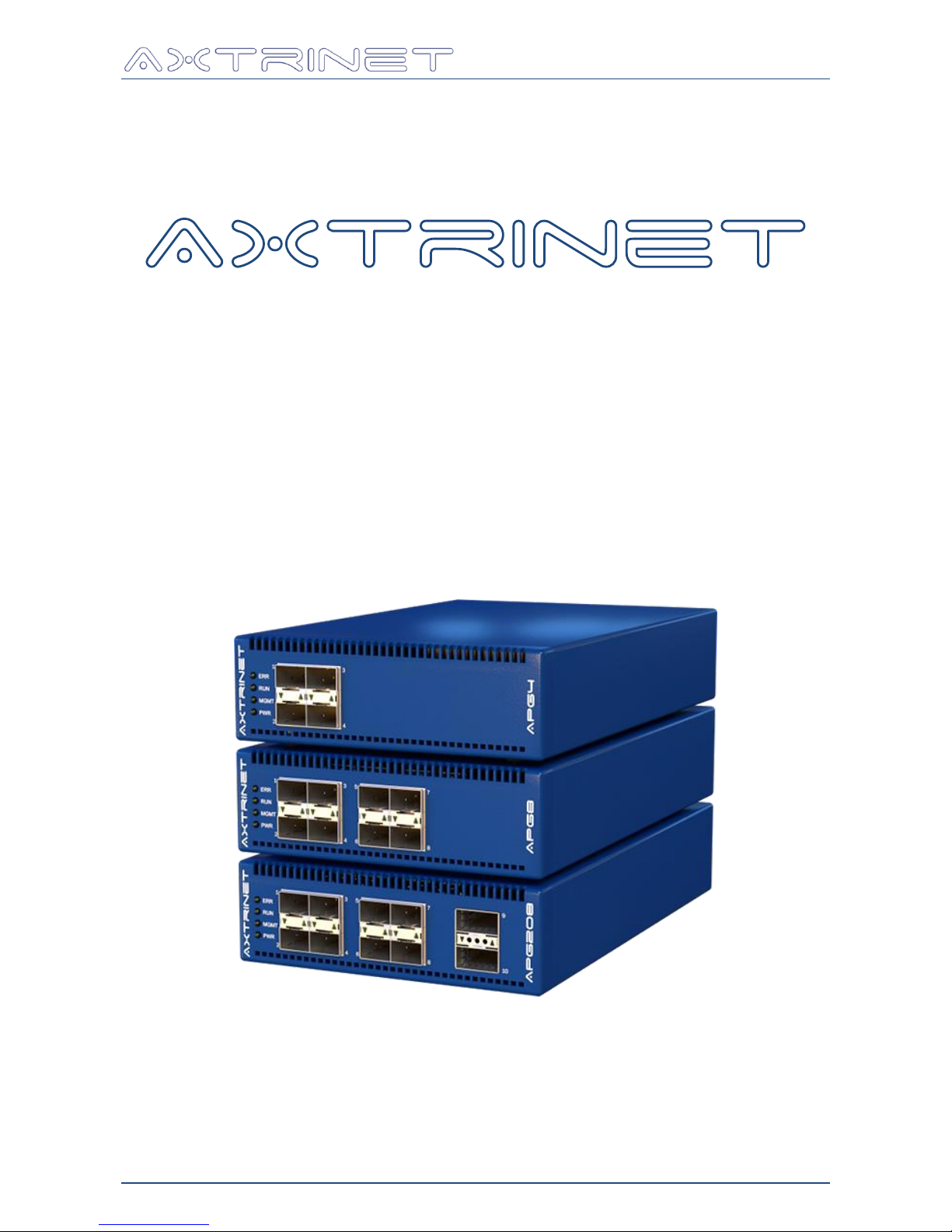
APG4 APG8 APG200 APG208
Page 2

Ethernet Packet Generator
USER GUIDE
APG-UG-V2-1 2 8 February 2018
Software Revisions
This document applies to the following software revisions:
APG Unit Firmware
Version 2.1
APG Processing Core
Version 6.010E
APG Control Interface
Version 2.1
Revision History
Date
Version
Changes
4 July 2016
0.4
Restricted Customer Release
Missing Linux installation information
11 August 2016
1.0
General release
Added Linux Installation (Section 2.3)
Modified 10GBase-T SFP limitations (Section 3.1.1)
Modified Front Panel LED behaviour (Section 3.1.3.1)
Added File-Save (Section 6.3.1)
Added Tools-Upgrade (Section 6.3.8)
3 November 2016
1.1
Added APG200
7 June 2017
2.0
Updated FCC statement
Added Port Topology changes (Sections 3.1.2 and 5.3),
including 40Gbps / 4x10Gbps support on QSFP+
interfaces.
Added Burst Mode (Section 6.5.1)
Added Packet/Second Mode (Section 6.5.1)
Added Packet Timestamps (Section 6.5.3)
Added Deep Packet Capture (Section 6.9)
Added 'Save to PCAP' (Section 6.9)
5 September 2017
2.0.2
Added Capture Buffer limits (Section 5.5)
Added Transmit Frame Length limits (Section 6.5.1)
Modified Capture Control description (Section 6.8.3)
8 February 2018
2.1
Added Save/Load Configuration (Section 6.3.2 & 6.3.3)
Local capture buffer sizes increased to 64KB (10Gbps),
and 256KB (40Gbps) (Sections 5.5 & 6.9)
Page 3
Ethernet Packet Generator
USER GUIDE
APG-UG-V2-1 3 8 February 2018
Document Conventions
INFORMATION:
Additional information to clarify functionality or usability
WARNING:
Clarification of unexpected or restricted functionality
CRITICAL:
Unit failure - contact Axtrinet for further support
Disclaimers
Axtrinet retains the right to make changes to this document at any time, without notice. The
information in this document is believed to be accurate and reliable. Axtrinet does not warrant
the accuracy or completeness of the information, text, graphics or other items contained within
this document.
Axtrinet provides the software and the documentation "as is" without warranties of any kind.
Axtrinet disclaims all warranties and representations of any kind relating to products, software
or services provided hereunder, whether express, implied, statutory, including without
limitation the implied warranties of merchantability, fitness for a particular purpose, accuracy,
or non-infringement of third party rights.
Axtrinet does not warrant that the software will in every case process all data correctly, or that
operation of the products, including software, will be uninterrupted, free from error, or secure.
The disclaimers in this section will not apply to the extent prohibited by applicable law.
The software is not designed, intended, or certified for use in components of systems intended
for the operation of weapons, weapons systems, nuclear installations, means of mass
transportation, aviation, medical systems, devices, implants, or equipment, pollution control,
hazardous substances management, or for any other dangerous application in which the failure
of the products could create a situation where bodily injury or death may occur. The use of the
software in any such application is solely at your own risk.
Copyright Statement
Copyright © 2016-2018 Xentech Solutions Limited, all rights reserved. The information
contained in this document is the property of Xentech Solutions Limited. No part of this
publication shall be reproduced, stored or transmitted in any form or by any means without the
prior written permission of Xentech Solutions Limited.
Trademarks
Axtrinet is a trading name and registered trademark of Xentech Solutions Limited, registered
in the UK.
Windows is a registered trademark or trademark of Microsoft Corporation, registered in the
U.S. and other countries.
Wireshark is a registered trademark of the Wireshark Foundation.
Page 4

Ethernet Packet Generator
USER GUIDE
APG-UG-V2-1 4 8 February 2018
Preface
About This Document
This document describes the Axtrinet Packet Generator hardware, the installation procedure,
and the User Manual for the APG Control Interface. It contains the following sections:
Section
Description
1. INTRODUCTION
Key features and benefits of the Axtrinet Ethernet
Packet Generators
2. INSTALLATION
Installation procedures for the Microsoft™ Windows™
and Linux USB drivers and Control Interface
3. HARDWARE INTERFACES
Physical properties of the unit
4. MANAGEMENT INTERFACES
Introduction to the Management Interfaces of the unit
5. TEST ENVIRONMENT & CONCEPT
Introduction to Ethernet packet generation, packet
structures and control
6. CONTROL INTERFACE
Detailed guide to the APG Control Interface
Related Documentation
[1] APG-GSG Axtrinet APG Getting Started Guide
[2] APG-TCL-UG Axtrinet APG TCL API Guide
[3] APG-HDR Axtrinet APG Header Definitions
[4] APG-SW-TC Axtrinet APG Software License Terms And Conditions
Visit www.axtrinet.com/documentation for the latest documentation.
Glossary
API Application Programming Interface
FCS Frame Checksum
IBG Inter-Burst Gap
IFG Inter-Frame Gap
pps Packets per Second
QSFP+ Quad Small Form-Factor Pluggable (40Gbps)
SFD Start-of-Frame Delimiter
SFP Small Form-Factor Pluggable (1Gbps)
SFP+ Small Form-Factor Pluggable (10Gbps)
TCL Tool Command Language
USB Universal Serial Bus
Page 5

Ethernet Packet Generator
USER GUIDE
APG-UG-V2-1 5 8 February 2018
Contents
1. INTRODUCTION .................................................................................................. 6
1.1 Main Features ....................................................................................................... 6
1.2 Benefits ................................................................................................................ 6
1.3 Safety Information ................................................................................................. 7
1.4 Care of the Product ................................................................................................ 7
1.5 Environmental ....................................................................................................... 8
1.6 Conformance ........................................................................................................ 8
1.7 Limited Hardware Warranty .................................................................................... 9
1.8 Software Licences and Support ................................................................................ 9
1.9 Contact Details ..................................................................................................... 10
2. INSTALLATION ................................................................................................. 11
2.1 Box Contents ....................................................................................................... 11
2.2 Minimum System Requirements ............................................................................. 11
2.3 Linux Installation .................................................................................................. 12
2.4 Windows Installation ............................................................................................. 13
2.5 Connecting the Hardware ...................................................................................... 14
2.6 Testing the Installation .......................................................................................... 15
2.7 Setting the IP Address ........................................................................................... 16
3. HARDWARE INTERFACES .................................................................................. 17
3.1 Front Panel Interfaces ........................................................................................... 17
3.2 Rear Panel Interfaces ............................................................................................ 20
3.3 Physical Specifications ........................................................................................... 21
4. MANAGEMENT INTERFACES .............................................................................. 22
4.1 APG Control Interface............................................................................................ 22
4.2 TCL Scripting ....................................................................................................... 22
5. TEST ENVIRONMENT & CONCEPTS .................................................................... 23
5.1 Definitions ........................................................................................................... 23
5.2 Unit Configuration................................................................................................. 24
5.3 Port Topology ....................................................................................................... 24
5.4 Transmit Path ...................................................................................................... 25
5.5 Receive Path ........................................................................................................ 27
6. CONTROL INTERFACE ....................................................................................... 29
6.1 Running the Control Interface ................................................................................ 29
6.2 Overview ............................................................................................................. 29
6.3 Menu Bar ............................................................................................................. 30
6.4 Connection Panel .................................................................................................. 37
6.5 Stream Configuration Panel ................................................................................... 40
6.6 Control Panel ....................................................................................................... 43
6.7 Counter Panel ...................................................................................................... 44
6.8 Port Status Window .............................................................................................. 45
6.9 Capture Data Display ............................................................................................ 48
6.10 Sliders ................................................................................................................ 48
Page 6

Ethernet Packet Generator
USER GUIDE
APG-UG-V2-1 6 8 February 2018
1. INTRODUCTION
Thank you for purchasing an Axtrinet™ APG Ethernet Packet Generator.
The Axtrinet APG Ethernet Packet Generators provide compact and affordable 40Gbps and
10Gbps Ethernet Packet Generator/Analysers with a simple-to-use Control Interface and an
open TCL API for third party scripting.
Ideally suited to applications in R&D, Test and Manufacturing environments, and 'on the road'
with Field Sales and Application Engineers, the Axtrinet APG Ethernet Packet Generators allow
reliable and affordable development and testing of:
Ethernet network equipment such as switches, routers, firewalls and network monitoring
devices
Data storage equipment with 10Gbps and 40Gbps Ethernet interfaces
Specialist devices such as FPGA accelerator NIC cards and offload appliances
Ethernet infrastructure installations encompassing cabling and switches
1.1 MAIN FEATURES
Highly configurable Ethernet Packet Generation
Full wire-speed operation on all ports
Industry standard QSFP+ and SFP+ ports
Real-time packet counts and error detection
Packet Capture for post-test analysis
Simple to use Control Interface for configuration and control
Clear LED status indication for unit operation and Ethernet traffic generation/reception
USB 2.0 port for easy set up and local management and 10/100Mbps Ethernet LAN
connection for flexible remote management
1.2 BENEFITS
Low cost allows multiple units to be deployed in a development environment – one per
desk
Easy to set up and use. Avoids the need for complex vendor specific programming skills
Ideal for integration into a manufacturing test environment using TCL scripting interface
Flexible choices of interfaces allows use with different speeds and media types, maximising
the investment across multiple projects
Small size, 1U high (44mm) and 146mm wide, for desk-top or rack shelf mounting (1/3
rack width)
Page 7
Ethernet Packet Generator
USER GUIDE
APG-UG-V2-1 7 8 February 2018
1.3 SAFETY INFORMATION
To prevent possible electrical shock, fire, personal injury, or damage to the
product, carefully read this safety information before attempting to install
or use the product.
In addition, follow all generally accepted safety practices and procedures
for working with and near electricity.
The product has been designed in accordance with the European standard publication
EN 61010-1:2010, and left the factory in a safe condition.
1.3.1 External Connections
To prevent injury or death, only use the power adapter and cord supplied
with the product.
To prevent injury, ensure that light or laser light sources (eg from SFPs
and QSFPs) are extinguished during connection or disconnection to optical
fibre inputs. Never direct an optical source towards a naked eye.
1.3.2 Environment
To prevent injury or death, do not use in wet or damp conditions, or near
explosive gas or vapour.
To prevent damage to the Packet Generator, use and store in the
recommended environment:
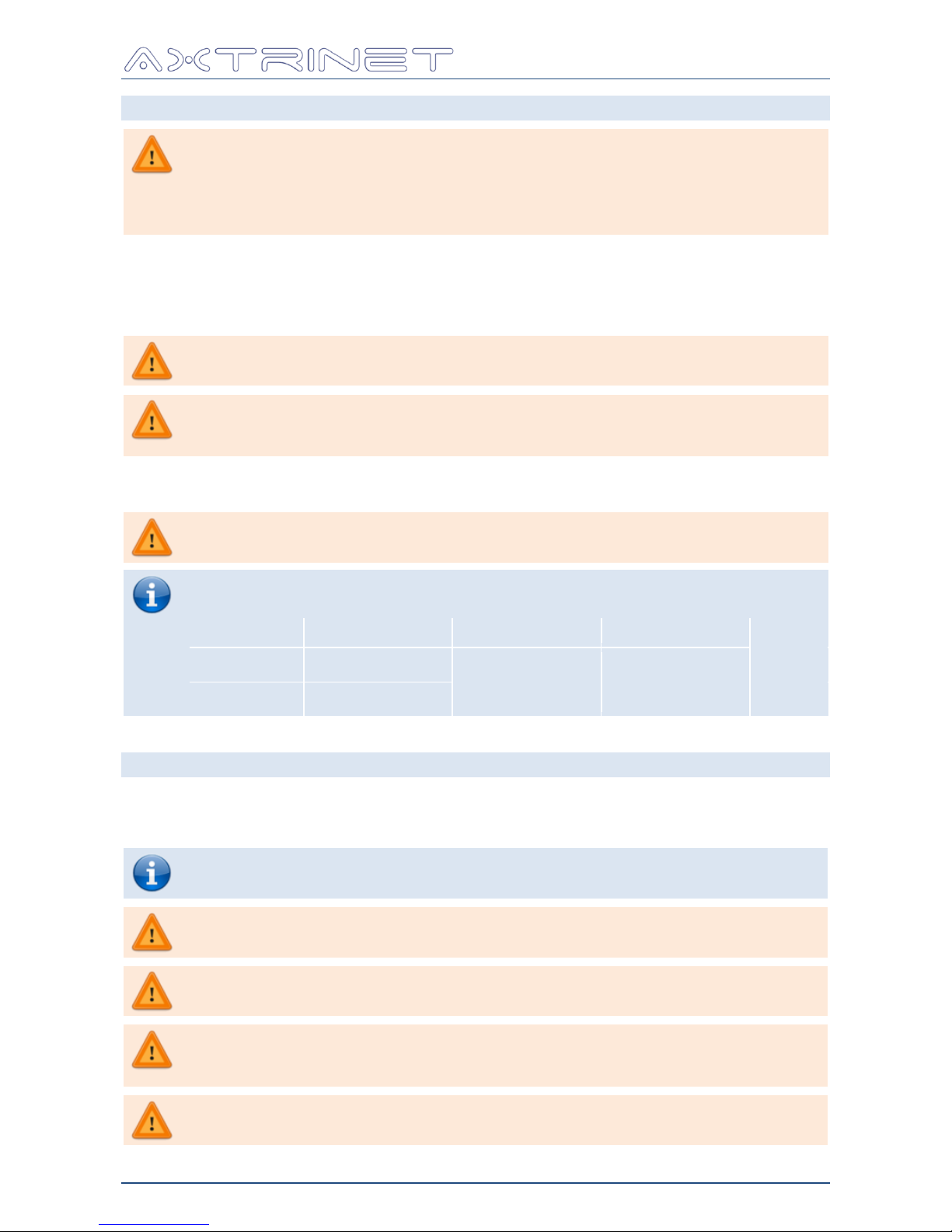
Temperature
Humidity
Altitude
Operating:
0°C - +40°C
5% to 90% RH
(non-condensing)
2000m
Storage:
-20°C - +55°C
1.4 CARE OF THE PRODUCT
The Axtrinet Packet Generator contains no user-serviceable parts. Repair and servicing require
specialised test equipment and must only be performed by Axtrinet. There may be a charge
for these services unless covered by the Axtrinet one year warranty.
Use a soft damp cloth to clean the Axtrinet Packet Generator.
Do not allow liquids to enter the product casing, as this may cause damage
to the electronics inside.
Do not tamper with or dismantle the Packet Generator.
Internal damage may affect performance and void the warranty.
Do not block the air vents at the front of the Packet Generator or the fan
exhaust at the rear. Overheating may affect the performance and damage
the internal electronics.
Do not insert any objects through the air vents.
Internal interference may damage the internal electronics.
Page 8
Ethernet Packet Generator
USER GUIDE
APG-UG-V2-1 8 8 February 2018
1.5 ENVIRONMENTAL
Disposal of Waste Electrical & Electronic Equipment
When an Axtrinet Packet Generator reaches the end of its useful life, Axtrinet
will arrange the responsible recycling of returned products. Where the
customer wishes to return the unit to Axtrinet, the customer will be responsible
for shipping the unit back to our facility. Before returning the unit, contact
Axtrinet Customer Services at [email protected] for more information.
1.6 CONFORMANCE
1.6.1 CE Notice
The product meets the intent of the EMC directive 2014/30/EU and is designed
and certified to EN61326-1:2013 Class A Emissions and Basic Immunity
standard.
This product is in conformity with the protection requirements of EU Council
Directive 2014/30/EU on the approximation of the laws of the Member States
relating to electromagnetic compatibility. Axtrinet cannot accept responsibility
for any failure to satisfy the protection requirements resulting from a nonrecommended modification of the product.
The limits for Class A equipment were derived for commercial and industrial
environments to provide reasonable protection against interference with
licensed communication equipment.
Warning: This is a Class A product. In a domestic environment, this product
may cause radio interference, in which case the user may be required to take
adequate measures.
The product meets the intent of the Low Voltage Directive 2014/35/EU and has
been designed to meet EN 61010-1:2010 Safety requirements for electrical
equipment for measurement, control, and laboratory use.
1.6.2 FCC Notice
This equipment is intended for use solely as industrial test equipment, and is
therefore exempt under Section 15.103(c) exemption rules.
However, this equipment has been verified to comply with the limits for a Class
A digital device, pursuant to Part 15 (CFR 47) of the FCC Rules. These limits are
designed to provide reasonable protection against harmful interference when
the equipment is operated in a commercial environment. This equipment
generates, uses, and can radiate radio frequency energy and, if not installed
and used in accordance with the instruction manual, may cause harmful
interference to radio communications. Operation of this equipment in a
residential area is likely to cause harmful interference in which case the user will
be required to correct the interference at their own expense.
Page 9

Ethernet Packet Generator
USER GUIDE
APG-UG-V2-1 9 8 February 2018
1.7 LIMITED HARDWARE WARRANTY
Axtrinet warrants upon delivery, and for a period of one year unless otherwise stated from the
date of delivery, that the product will be free from defects in material and workmanship.
Axtrinet shall not be liable for a breach of the warranty if the defect has been caused by wilful
damage, negligence, abnormal working conditions or failure to follow Axtrinet's written advice
on the storage, installation, commissioning, use or maintenance of the product; or if the
Customer alters or repairs the product without the written consent of Axtrinet.
The maximum liability of Axtrinet under this warranty is limited to the purchase price of the
product covered by the warranty.
EXCEPT AS SPECIFICALLY PROVIDED ABOVE OR AS REQUIRED BY LAW, THE WARRANTIES
AND REMEDIES STATED ABOVE ARE EXCLUSIVE AND IN LIEU OF ALL OTHERS, ORAL OR
WRITTEN, EXPRESS OR IMPLIED. ANY OR ALL OTHER WARRANTIES, INCLUDING IMPLIED
WARRANTIES OF MERCHANTABILITY, FITNESS FOR A PARTICULAR PURPOSE AND NONINFRINGEMENT OF THIRD PARTY RIGHTS ARE EXPRESSLY EXCLUDED. AXTRINET SHALL NOT
UNDER ANY CIRCUMSTANCES BE LIABLE TO ANY PERSON FOR ANY SPECIAL, INCIDENTAL,
INDIRECT OR CONSEQUENTIAL DAMAGES, INCLUDING WITHOUT LIMITATION, DAMAGES
RESULTING FROM USE OR MALFUNCTION OF THE PRODUCT, LOSS OF PROFITS OR REVENUES
OR COSTS OF REPLACEMENT GOODS, EVEN IF AXTRINET IS INFORMED IN ADVANCE OF THE
POSSIBILITY OF SUCH DAMAGES.
Should a product fail to perform as described above within the warranted period, it will be
repaired or replaced with the same or functionally equivalent product by Axtrinet, at its
discretion, free of charge provided you: (1) return the product to a Axtrinet designated repair
facility with shipping charge prepaid or by using the Returns Label provided, and (2) provide
Axtrinet with proof of the original date of purchase.
Prior to returning any defective product, the end customer or the reseller from whom the end
customer originally purchased the product must obtain a Return Materials Authorisation (RMA)
number from Axtrinet. Unless otherwise agreed, all defective products should be returned to
Axtrinet with shipping charges prepaid. Axtrinet will not accept collect shipments.
Repaired or replacement products will be returned to you with shipping charges prepaid.
Replacement products may be refurbished or contain refurbished materials. If Axtrinet, by its
sole determination, is unable to repair or replace the defective product, it will refund the
depreciated purchase price of the product.
An Extended Hardware Warranty is available for purchase; please contact Axtrinet or your
reseller for more information.
1.8 SOFTWARE LICENCES AND SUPPORT
See the Axtrinet APG Software License Terms & Conditions [4].
Email based software support is included in the purchase price for the first 12 months after
delivery. Extended Software Support is available for purchase; please contact Axtrinet or your
reseller for more information.
Page 10

Ethernet Packet Generator
USER GUIDE
APG-UG-V2-1 10 8 February 2018
1.9 CONTACT DETAILS
Technical assistance is available from Axtrinet at the following address:
Address:
Xentech Solutions
Suite 6 Stanta Business Centre
3 Soothouse Spring
St Albans
AL3 6PF
UK
Phone:
+44 (0)1727 867795
Email:
Technical Support:
Sales:
Web Site:
www.axtrinet.com
Page 11

Ethernet Packet Generator
USER GUIDE
APG-UG-V2-1 11 8 February 2018
2. INSTALLATION
This section describes the driver, APG Control Interface and TCL API installation process on a
host PC running Linux or Windows.
2.1 BOX CONTENTS
The shipping carton contains:
APG Unit
Universal Desktop 12Vdc 5A Power Supply & local mains lead
1m USB Type B lead
Getting Started Guide
4x Rubber Feet
Axtrinet Resource CD for Windows and Linux:
USB Drivers
APG Control Interface Application
APG TCL API
Documentation
Visit www.axtrinet.com/documentation for the latest documentation and software.
2.2 MINIMUM SYSTEM REQUIREMENTS
Processor
Pentium-class processor or equivalent
Memory
2GB (4GB recommended)
Disk Space
15MB
OS
64bit (x86_64) Linux systems
Microsoft Windows 7
Microsoft Windows 8.x
Microsoft Windows 10.x
Interfaces
Minimum: USB 2.0
Preferred: USB 2.0 & 10/100Base-T
Page 12

Ethernet Packet Generator
USER GUIDE
APG-UG-V2-1 12 8 February 2018
2.3 LINUX INSTALLATION
The Axtrinet APG Linux package contains the GUI application and the system configuration file.
The GUI requires X-Windows to be running.
There are 4 installation formats provided for convenience:
Simple tar
Pacman
RPM
Deb
Pick the one that suits the distribution and the package should install with the normal package
handling tools or use the commands below.
Currently all packages are for 64bit (x86_64) linux systems. The package files may not have
all package dependencies because package names vary between different linux distributions.
See the notes in the Dependencies section below for package dependencies.
Pacman
Install with
pacman -U apgcontrol-2.1-1-x86_64.pkg.tar.xz
Remove with
pacman -R apgcontrol
RPM
Install with
rpm -U apgcontrol-2.1-1.x86_64.rpm
or
yum localinstall apgcontrol-2.1-1.x86_64.rpm
Remove with
rpm -e apgcontrol
There are a set of MD5/SHA1/SHA256 sums for the package files.
The package includes a desktop link that should appear under Network tools.
If it doesn't work
Provided the package install worked, once installed there should be an executable 'apgcontrol'
in /usr/bin. If it does not run then check for missing libraries with:
ldd /usr/bin/apgcontrol
Dependencies
The following base packages are required but will normally already be installed:
fontconfig, libxft, libx11
The following optional dependencies are also required for some functionality:
To connect to USB ports libusb (libusb-1.0.so) is required.
If it is not present, USB connected units will not appear.
In addition to run the scripting interface you will require to have a tcl package (provide
tclsh, libtcl8.6.so) installed and to run the test suite tk (provide wish) to run the UI and
texlive or texlive-bin (provide pdflatex) to create the pdf report documents.
Page 13
Ethernet Packet Generator
USER GUIDE
APG-UG-V2-1 13 8 February 2018
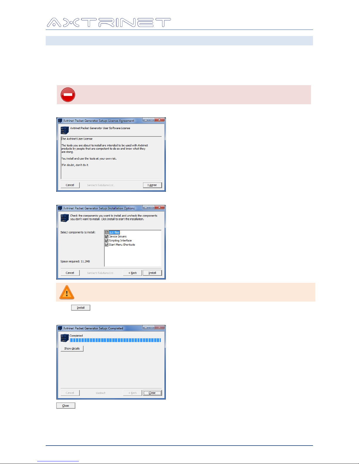
2.4 WINDOWS INSTALLATION
1. Insert the CD.
2. Locate "apg-install.exe" in the Windows directory
3. Run the installation file and follow the on-screen instructions to install the USB driver, APG
Control Interface GUI and the APG TCL API.
DO NOT CONNECT THE AXTRINET PACKET GENERATOR TO THE
WINDOWS PC UNTIL THE INSTALLATION IS COMPLETE.
4. Read and accept the software Licence Agreement:
5. Select the components to install:
The installer will only update the installed components if a newer
component is available.
Click to start installing the selected components.
6. The window changes to display the installation progress.
7. completes the installation process.
8. In addition, to run the scripting interface you will require to have a tcl package (provide
tclsh) installed; to run the Test Suite GUI you will require tk (provide wish); and to
generate test reports you will require TexLive or MiKTex (provide pdflatex).
Page 14
Ethernet Packet Generator
USER GUIDE
APG-UG-V2-1 14 8 February 2018
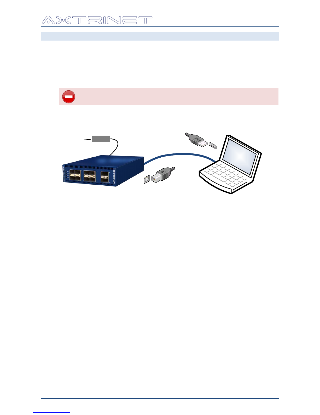
2.5 CONNECTING THE HARDWARE
Attach the ac mains supply lead to the power adapter, connect the adapter to the unit and
apply power.
The POWER LED will be illuminated ORANGE for ~60 seconds while the hardware
configures.
The POWER LED will turn GREEN after successful configuration, or RED if the hardware
has failed to configure.
If the POWER LED turns RED after configuration, contact AXTRINET
for further support.
Connect the management PC to the APG unit using the USB Type B lead (provided).
USB
Type B
Type A
AC
Supply
12Vdc
AC/DC Adapter
Page 15
Ethernet Packet Generator
USER GUIDE
APG-UG-V2-1 15 8 February 2018
2.6 TESTING THE INSTALLATION
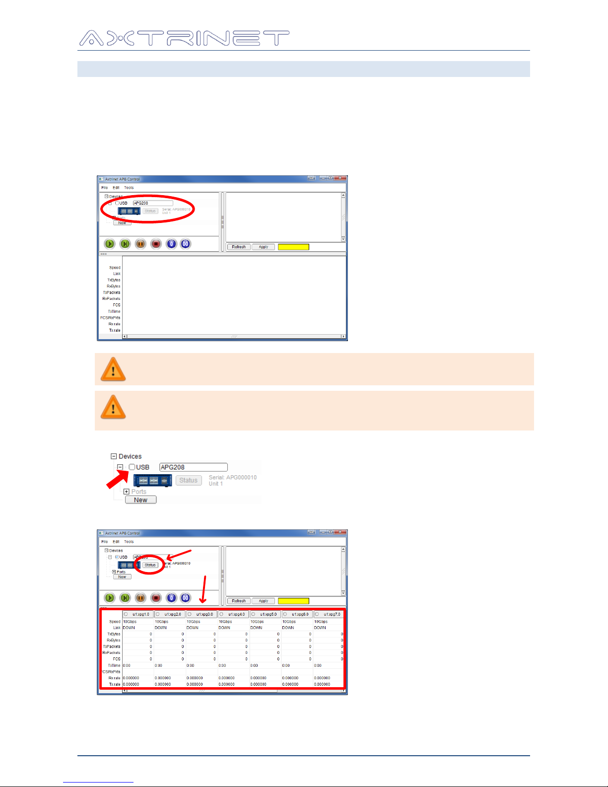
Start the APG Control Interface:
On Linux, click the home / Axtrinet Control icon or execute user/bin/apg_control
On the Windows Start menu, locate the Axtrinet directory and click on the APG Control
icon.
The APG Control Interface management window will be displayed and the new unit will
appear as a USB connection:
If the unit does not appear in the Control Interface, check that the unit is
turned on and the USB lead is connected.
If installing the drivers onto a PC for the first time, it may be necessary to
re-run the installation process after the device has been connected as the
USB drivers may not be enabled.
To connect to the unit, click on the Checkbox next to the device.
The unit port counters and unit Status button are displayed:
The drivers and APG Control Interface have been successfully installed.
Page 16
Ethernet Packet Generator
USER GUIDE
APG-UG-V2-1 16 8 February 2018
2.7 SETTING THE IP ADDRESS
The default settings are:
IP Address
192.168.1.100
Mask
255.255.255.0
Gateway
0.0.0.0
You may need to contact your Network Administrator to obtain the required
IP and Gateway Addresses
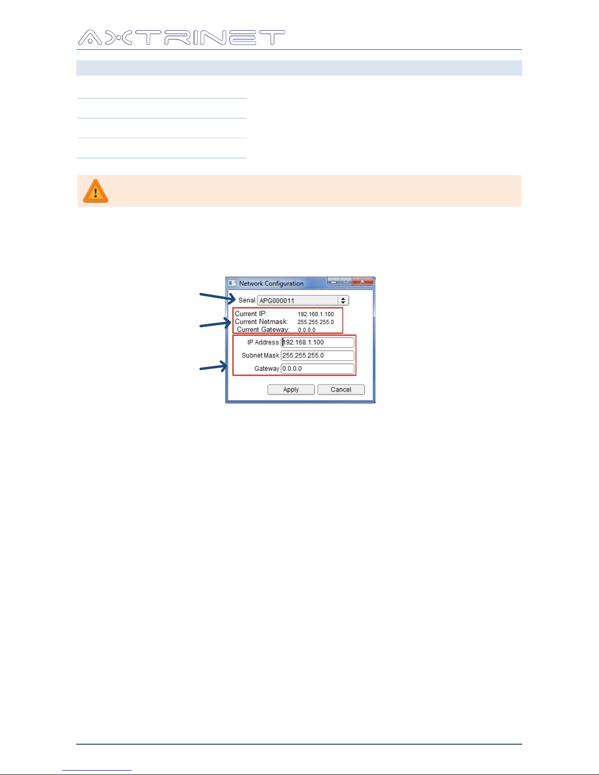
To change the IP Address of the unit:
On the MENU BAR: Edit → Network Configuration.
The IP Configuration Window opens:
Current Settings
New Settings
Unit
Set the IP Address, Mask and Gateway Address, then click APPLY
For further details, see Section 6.3.6.
Page 17
Ethernet Packet Generator
USER GUIDE
APG-UG-V2-1 17 8 February 2018
3. HARDWARE INTERFACES
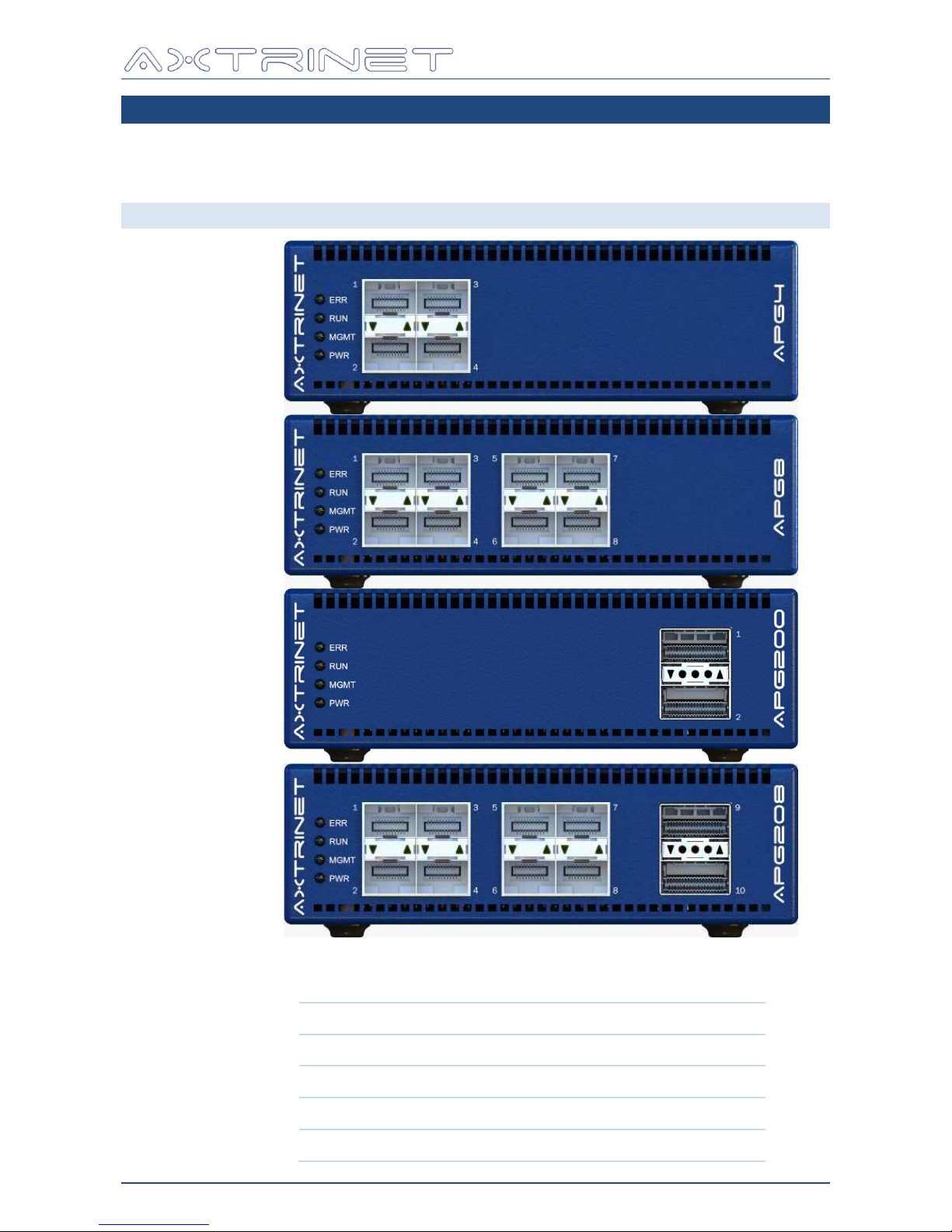
The packet generator ports (SFP+ & QSFP+) are on the front of the unit, and the management
and power interfaces are on the rear.
3.1 FRONT PANEL INTERFACES
Status
LEDs
10Gbps
SFP+
10Gbps
SFP+
40Gbps
QSFP+
APG208
APG8
APG4
APG200
10Gbps SFP+
40Gbps QSFP+
APG4 4 0
APG8 8 0
APG200 0 2
APG208 8 2
Page 18
Ethernet Packet Generator
USER GUIDE
APG-UG-V2-1 18 8 February 2018
3.1.1 SFP+ Interfaces
The SFP+ interfaces will support 10Gbps SFPs that meet SFF-8431 MSA.
Only 10Gbps transceivers are supported in V2.1 Embedded Software
The list of verified SFPs is available on the Axtrinet website:
www.axtrinet.com/transceivers.html
The SFP+ interfaces will also support certain 10GBase-T transceivers that exceed the SFF-8431
power budget of 1W, but only in the upper ports (1,3,5,7) due to thermal limitations.
10GBase-T transceivers are disabled in the lower ports (2,4,6,8)
3.1.2 QSFP+ Interfaces
The QSFP+ interfaces will support 40Gbps QSFPs that meet SFF-8436 MSA.
The list of verified QSFPs is available on the Axtrinet website:
www.axtrinet.com/transceivers.html
The QSFP+ interfaces can be configured in 40Gbps mode (default) or 4X10Gbps mode, where
each of the 10Gbps lanes that comprise the 40Gbps link are managed independently (Section
5.3). Switching between 40Gbps and 4x10Gbps modes is performed in the Port Control
Window (Section 6.8.1).
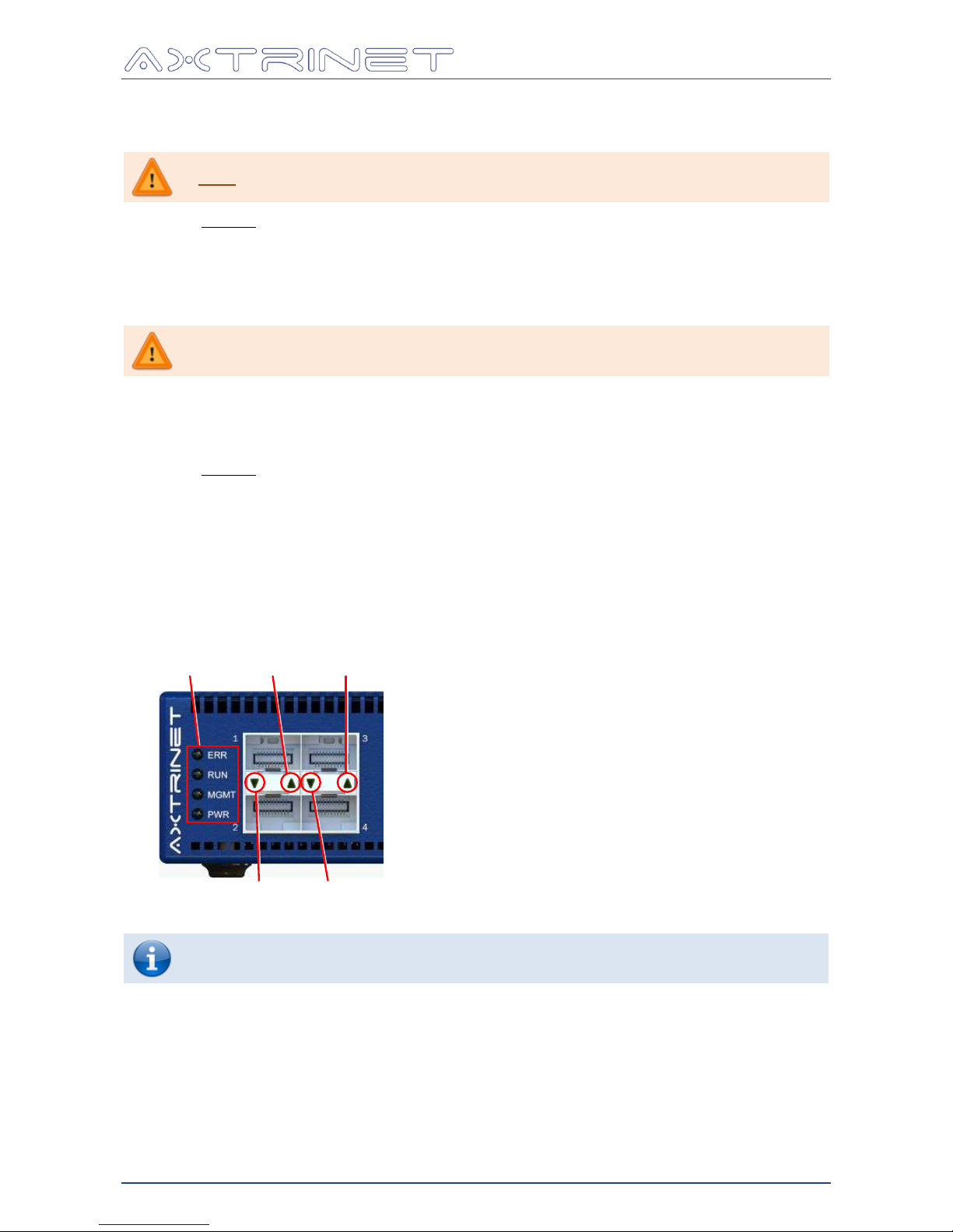
3.1.3 LED Indicators
Port 1
LED
Port 3
LED
Port 2
LED
Port 4
LED
System
LEDs
Some APG units are fitted with SFP Cages with four LEDs per vertical port pair.
In all cases, only the outer LEDs are used. The inner two LEDs are not used.
Page 19
Ethernet Packet Generator
USER GUIDE
APG-UG-V2-1 19 8 February 2018
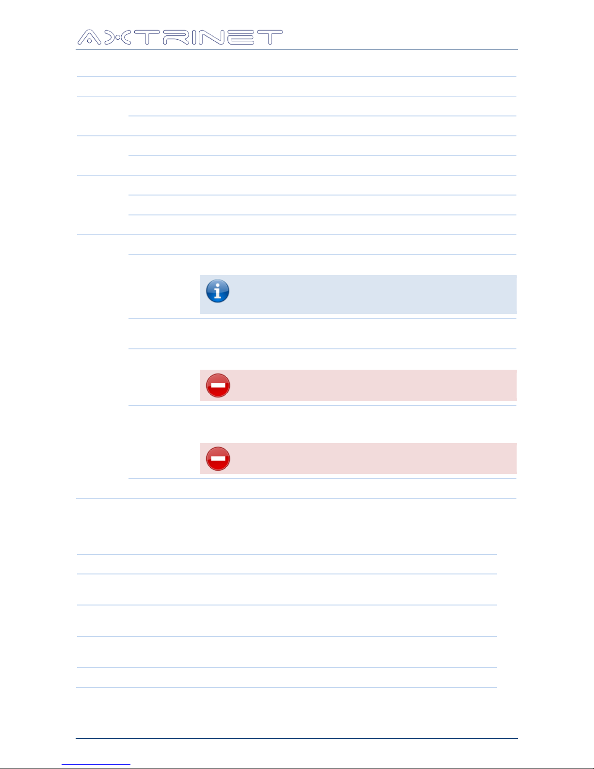
3.1.3.1 System LEDs
LED
Colour
Description
ERR
RED
Operational Unit Error eg over-temperature
OFF
Unit OK
RUN
ON
Green/Amber/Red on/flashing under automated test control
OFF
Normally OFF
MGMT
GREEN
Configuration or Status information is being read from the unit
AMBER
Configuration or Status information is being written to the unit
OFF
Unit is not being actively managed
PWR
GREEN
Unit is powered and OK
AMBER
Unit is powered and configuring the hardware
After applying the power, the POWER LED will be
illuminated ORANGE for ~60 seconds while the hardware
configures.
Flashing
AMBER
Processing downloaded file (3-4 minutes)
RED/AMBER
Failed to configure the hardware
Power cycle the unit. If the problem persists,
contact AXTRINET for Technical Support.
RED
Initial state immediately after the power has been applied.
If the LED remains on for >5 sec, critical hardware fault detected
Power cycle the unit. If the problem persists,
contact AXTRINET for Technical Support.
OFF
Unit is not powered
3.1.3.2 Port LEDs
One LED per port, integrated into the transceiver cage:
Colour
Meaning
GREEN
Steady Link OK, no traffic
Flashing Transmit or Receive Traffic Activity
ORANGE
Steady Cable detected, Transmit disabled
→ set TXENABLE on Port Control tab (Section 6.8.1)
RED
Steady No cable detected, Transmit disabled
→ set TXENABLE on Port Control tab (Section 6.8.1)
OFF
No Link
Page 20
Ethernet Packet Generator
USER GUIDE
APG-UG-V2-1 20 8 February 2018
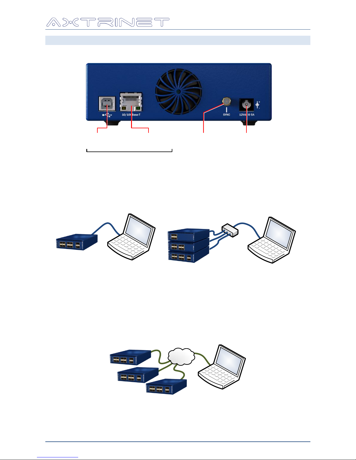
3.2 REAR PANEL INTERFACES
USB and 10/100Base-T Ethernet interfaces provide management access to the device.
USB 10/100Base-T
Ethernet
Management Interfaces
Sync Power
12Vdc @ 5A
3.2.1 USB Interface
The USB 2.0 Type B interface can be used to provide a connection to the PC running the
Control Interface Application Software.
USB
Hub
a) Direct Connection b) Multiple APG units connected through USB Hub
After installing the Control Interface Application Software, no further configuration is required
to enable the USB interface.
3.2.2 10/100Base-T Ethernet Interface
The 10/100Base-T RJ45 interface can be used to provide a network connection to the PC
running the Control Interface Application Software or TCL API Scripting.
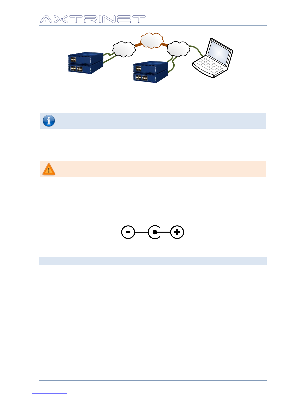
The Ethernet connection can be direct, or across a LAN, or WAN to a remote office.
c) Multiple APG units connected through LAN
LAN
Page 21
Ethernet Packet Generator
USER GUIDE
APG-UG-V2-1 21 8 February 2018
d) Multiple APG units connected through WAN
LAN
LAN
WAN
After installing the Control Interface Application Software, the Network Interface must be
configured using the USB Interface to set the IPV4 Address, Mask and Gateway (Section
6.3.6).
Up to two Ethernet connections are supported by the Ethernet Interface, eg two
Control Interface sessions or one Control Interface session and one TCL session.
3.2.3 Sync Interface
The Sync Interface allows multiple units to be connected together for synchronous transmit
START, STEP and STOP control.
The Sync Interface is reserved for future use
3.2.4 Power
The APG unit requires a 12V 5A from the ac/dc power supply provided.
The DC Jack is 2.1mm internal diameter, 5.5mm external diameter, 9.5mm minimum length,
with the centre pin positive.
0V 12V
3.3 PHYSICAL SPECIFICATIONS
Width: 140mm (5.51")
Depth: 228mm (8.97")
Height: 44mm (1.73")
Weight: 1.20 kg (2.65 lb)
Page 22
Ethernet Packet Generator
USER GUIDE
APG-UG-V2-1 22 8 February 2018
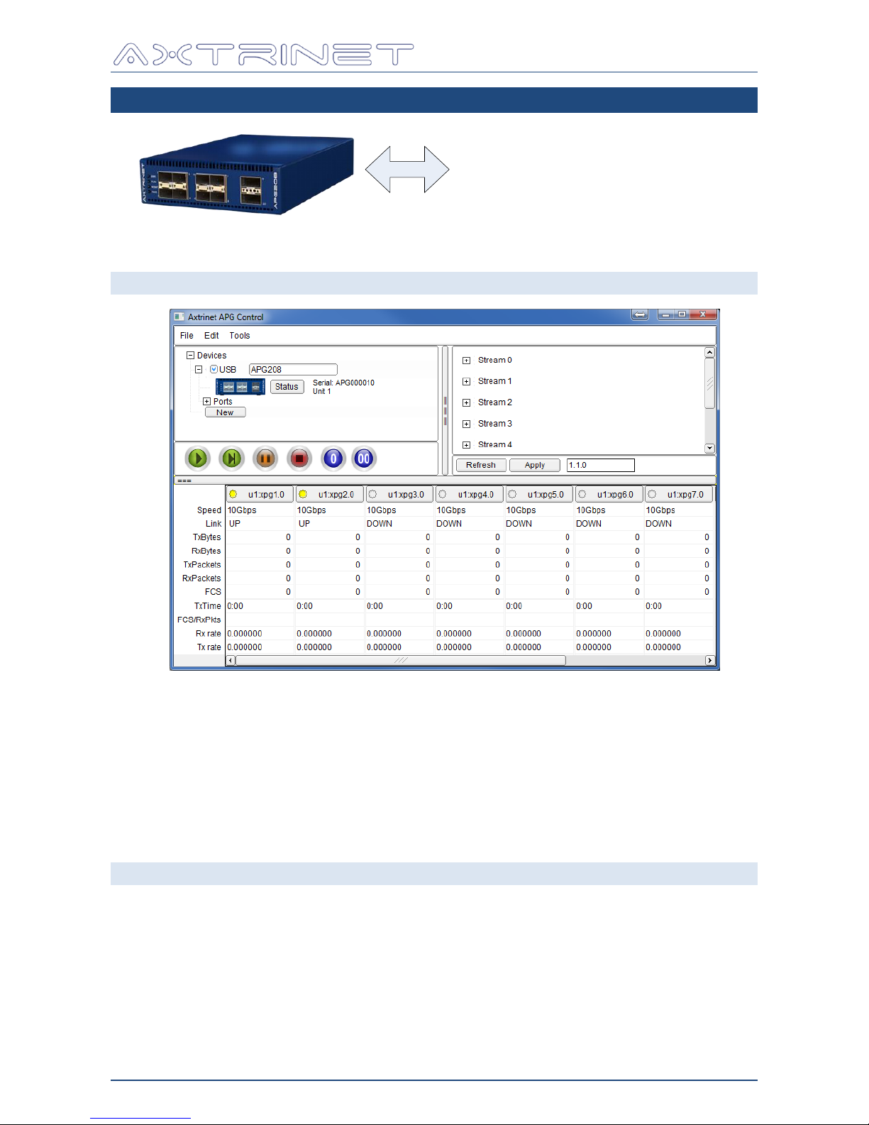
4. MANAGEMENT INTERFACES
APG Control Interface
APG TCL Scripting
4.1 APG CONTROL INTERFACE
The Axtrinet APG Control Interface is a custom application providing:
unit, port and stream configuration and status
port control (start, step, stop)
packet counters (packets, bytes, errors)
packet capture tools
The Axtrinet APG Control Interface is described in Section 6.
4.2 TCL SCRIPTING
The Axtrinet APG API provides a TCL scripting interface for automated test generation.
The API provides access to:
unit, port and stream configuration and status
port control (start, step, stop)
packet counters (packets, bytes, errors)
packet capture tools
The Axtrinet APG API Interface is described in the TCL API Guide [2].
Page 23
Ethernet Packet Generator
USER GUIDE
APG-UG-V2-1 23 8 February 2018
5. TEST ENVIRONMENT & CONCEPTS
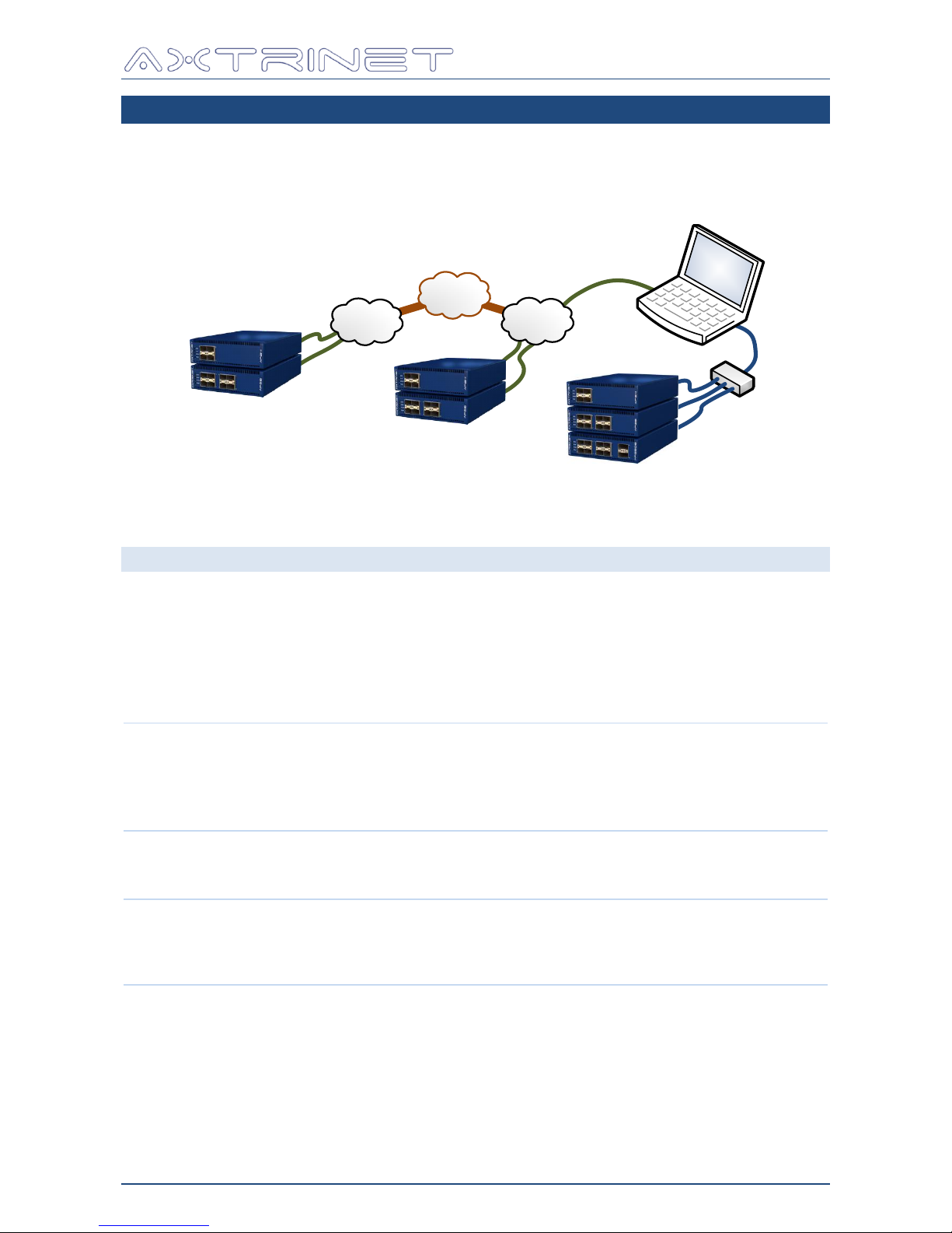
The Test Environment consists of one or more Axtrinet Packet Generators. A single unit may
be connected over a direct USB connection, or multiple units may be connected over USB or
Ethernet. The units may be located in the same location, or in geographically separate
locations connected by a WAN.
LAN
LAN
WAN
USB
Hub
All accessible units can be managed through the same Control Interface or TCL scripting
interface.
5.1 DEFINITIONS
UNIT
A unit is a single physical Axtrinet Packet Generator (eg APG208).
A unit is assigned a UNITID when the management connection is first opened
using the Control Interface (or TCL API). The UNITID is fixed for the duration of
the Control Interface session, and is used to uniquely identify a unit during the
session. The UNITIDs will be reassigned if the application is restarted.
The UNITID can be seen in the Connection Panel (Section6.4) and in the port
label in the Counters Panel (Section 6.6).
PORT
A PORT is a physical aperture on the unit (SFP+ or QSFP+).
The port-level functions configure the port settings and monitor the port status
(Section 6.8.1)and view the captured packets (Section 6.8.2).
Ports must be selected (Section 6.6) to start/step/stop transmission (Section
6.6).
SUBPORT
Where a QSFP+ port can be configured into different topologies (eg 40Gbps or
4x10Gbps), the PORTID is qualified with a SUBPORT.
Subports are numbered from 1.
MODULE
A MODULE is a SFP+ or QSFP+ transceiver, and must be inserted into a port
aperture to enable a link.
The module-level functions configure the module settings (Section 6.8.1), and
monitor the module status (Section 6.8.2).
STREAM
A transmit stream generates a controlled number of Ethernet frames with a
defined length and rate (Section 6.5.1); fixed header configuration with a fixed
or varying header contents (Section 6.5.2); and a fixed or varying payload
(Section 6.5.3).
The outputs from the eight stream generators are multiplexed into a single
stream for transmission from a port.
Page 24
Ethernet Packet Generator
USER GUIDE
APG-UG-V2-1 24 8 February 2018
5.2 UNIT CONFIGURATION
The unit, port and stream configuration is stored on the unit.
The APG Control Interface provides a graphical interface to view and modify the configuration
stored on the unit, to view the counters and the captured data. The current configuration can
be saved locally to a named file and then loaded onto a unit later.
Unit, port and stream configurations can be modified within the Control Interface and APPLIED
to the unit.
The unit will retain its configuration over a power cycle.
5.3 PORT TOPOLOGY
Port Topology defines the physical port configuration (eg 40Gbps, 4x10Gbps), rather than the
interface type (eg QSFP+).
5.3.1 SFP+ Ports
The SFP+ Port Topology is fixed 10Gbps only.
5.3.2 QSFP+ Ports
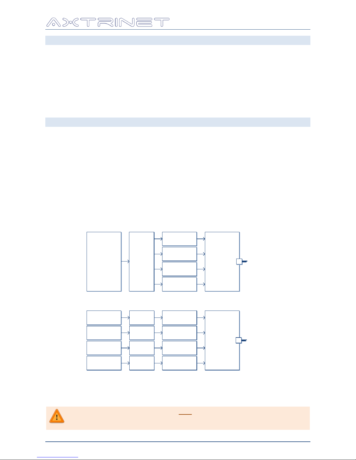
The QSFP+ interface is a composite port made up of 4x 10Gbps. The topology can be
configured in 40Gbps mode (default) or 4X10Gbps mode, where each of the 10Gbps lanes that
comprise the 40Gbps link are managed independently.
Changing the port topology of a QSFP+ port changes both the transmit and receive paths.
Stream
Generators
Stream
Generators
Stream
Generators
Stream
Generators
10Gbps
MAC
10Gbps
Serdes
10Gbps
MAC
10Gbps
Serdes
10Gbps
MAC
10Gbps
Serdes
10Gbps
MAC
10Gbps
Serdes
QSFP+
Module
Stream
Generators
40Gbps
MAC
10Gbps
Serdes
10Gbps
Serdes
10Gbps
Serdes
10Gbps
Serdes
QSFP+
Module
MPO/DA
MPO/DA
a) QSFP+ Port in 40Gbps Topology (default)
b) QSFP+ Port in 4x10Gbps Topology
Switching between 40Gbps and 4x10Gbps topologies is performed in the Port Control Window
(see Section 6.8.1).
Mixed topology of the QSFP+ ports is only available with Port 9 at 4x10Gbps, and
Port 10 at 40Gbps. Setting Port 9 to 40Gbps or Port 10 to 4x10Gbps topologies
will automatically switch the other port into the same mode.
Page 25
Ethernet Packet Generator
USER GUIDE
APG-UG-V2-1 25 8 February 2018
5.4 TRANSMIT PATH
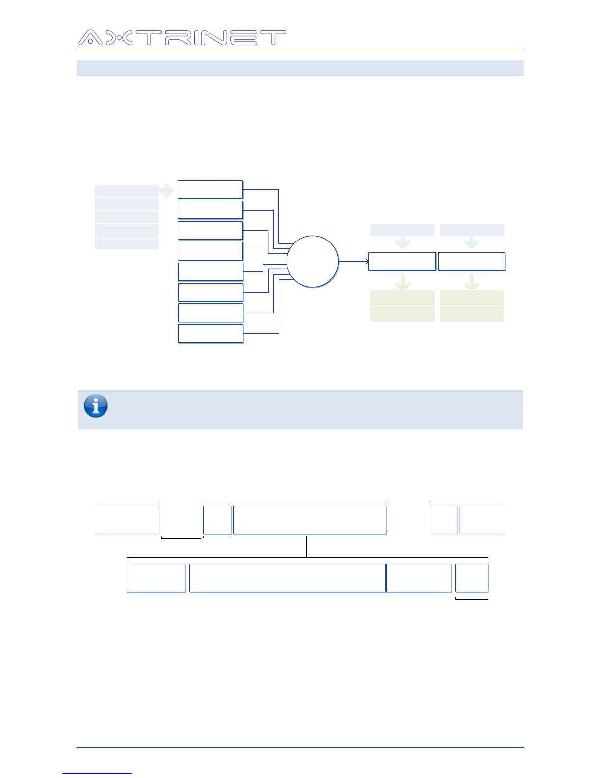
Each port contains a transmit engine that comprises:
8 parallel independent configurable Ethernet stream generators
Stream multiplexer
Transmit port configuration and status
Module configuration and status
STREAM 0
STREAM 1
STREAM 2
STREAM 3
STREAM 4
STREAM 5
STREAM 6
STREAM 7
+
PORT N MODULE
Status
Status
Enable
Rate
Length
Header
Payload
Enable Enable
ContentsCounters
Per Stream:
The streams are processed in a round-robin sequence, transmitting a packet if it queued and
ready to send.
To bring a link up, both the port and module must be enabled.
To transmit a stream, the port, module and stream must be enabled.
The transmit mode must be CONTINUOUS or a non-zero BURST.
5.4.1 Stream Generation
The Stream Generator defines an Ethernet frame:
HEADERS PAYLOAD
TIMESTAMP
(OPTIONAL)
FRAME LENGTH
4 BYTES
FIXED, INCREMENTING, DECREMENTING, RANDOM
HEADER AND FIELD LENGTHS NOT DRAWN TO SCALE
SFD
Start-of-
Frame
Delimiter
FRAME
IPG
Inter
Packet
Gap
12 BYTES(min)
8 BYTES
PACKET
FRAME
NEXT PACKET
FRAME
PREVIOUS PACKET
SFDIPG
FCS
Frame
Checksum
A transmit stream generates a controlled number of Ethernet frames at a controlled length and
rate; with a fixed header configuration, fixed or varying header contents, and a fixed or
varying payload.
Each stream can be enabled or disabled (Section 6.5.1).
Page 26
Ethernet Packet Generator
USER GUIDE
APG-UG-V2-1 26 8 February 2018
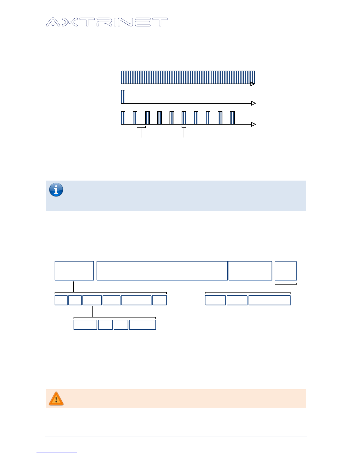
The stream transmit mode defines how the packets are generated: either Continuously; as a
Single Burst of BURST LENGTH packets; or a Multiple Burst of BURST LENGTH packets,
repeated BURST COUNT times, separated by BURST GAP (Section 6.5.1).
T=0
CONTINUOUS
SINGLE BURST
MULTIPLE BURSTS
BURST
GAP
BURST
LENGTH
BURST COUNT = 1
BURST COUNT = 10
The stream transmit rate defines how quickly the packets are generated; either a percentage
of the maximum rate; packets per second; or a gap defined by transmit clock cycles (Section
6.5.1).
Care should be taken to ensure that the cumulative stream transmit rates does not
exceed the port capacity.
If the cumulative stream transmit rates does exceed the port capacity, the port will
transmit at wire rate, but the streams will transmit at a lower rate than configured.
The length defines the total length of the frame in bytes, including the headers, payload,
timestamp (if enabled) and 4-byte Frame Checksum (FCS). The length can be fixed, or
incrementing, decrementing or random over a range (Section 6.5.1).
The HEADER is created by adding header types (eg MAC, VLAN, IPV4) to the stream
(Section 6.5.2).
HEADERS PAYLOAD FCS
TIMESTAMP
(OPTIONAL)
4 BYTES
DA SA VLAN IPV4 TCP
EG:
TYPE
FIXED, INCREMENTING, DECREMENTING, RANDOM
PID
EG:
PRI CFI VID
FIXED FIXED
INCREMENTING
DECREMENTING
RANDOM
FIXED FIXED
HEADER AND FIELD LENGTHS NOT DRAWN TO SCALE
SEQ
INCREMENTING
4 BYTES
TIMESTAMP
TIME
8 BYTES
ID
FIXED
4 BYTES
The payload can be fixed, or incrementing, decrementing or random (Section 6.5.3)
The payload may optionally include a 'Timestamp' field, comprising an ID, sequence number
and timestamp (Section 6.5.3).
The Timestamp ID field is fixed at 0x0 in APG Control Interface
Version 2.1.
Page 27
Ethernet Packet Generator
USER GUIDE
APG-UG-V2-1 27 8 February 2018
The Sequence Number is set to zero when the unit powers up, and
increments continuously for each packet transmitted with the Timestamp
field enabled.
The Sequence Number will wrap after 232 (4,294,967,296) packets.
Wire-rate 64 byte packets at 40Gbps will take 1 min 12 secs.
It is not possible to reset the Sequence Number in APG Control Interface
Version 2.1.
The Timestamp indicates the time in 8ns cycles since the unit was reset.
It is not possible to reset the Timestamp in APG Control Interface
Version 2.1.
A port can be enabled or disabled (Section 6.6).
Port link status, link speed and transmit counters (Section 6.6) are available.
A module can be enabled or disabled (Section 6.8.1).
The module type, vendor and capabilities are available (Section 6.8.2).
5.5 RECEIVE PATH
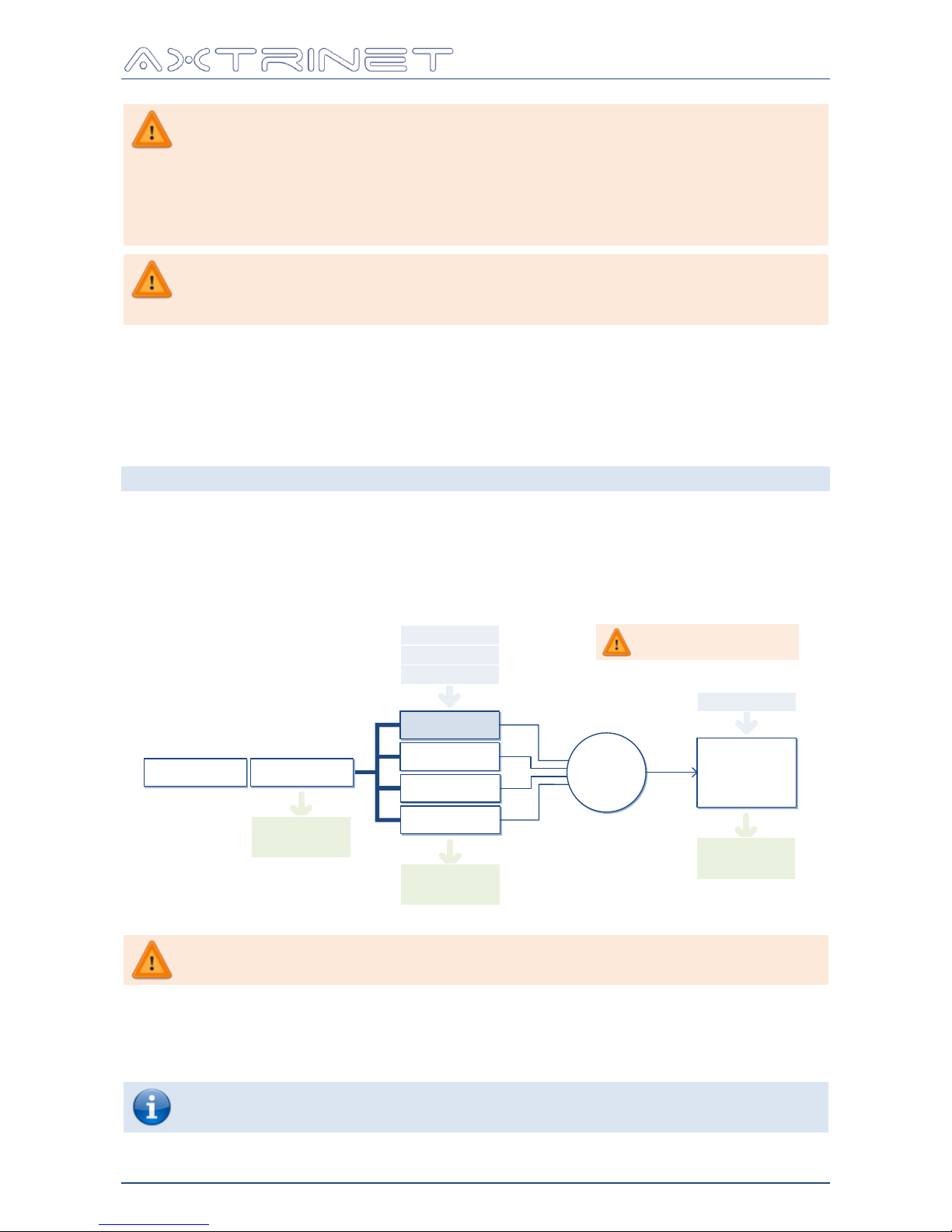
Each port contains a receive path that comprises:
Receive port status and counters
Filter stream multiplexer
Configurable Capture Buffer
FILTER 0 is reserved for
internal use only
FILTER 0
FILTER 1
FILTER 2
FILTER 3
+
Mask
PORT NMODULE
Receive
Counters
CAPTURE
BUFFER
Filter
Counters
Captured
Data
Match
Enable
Control
Configurable Capture Filters are not supported in APG Control Interface
Version 2.1. All received port traffic is forwarded to the capture buffer.
A 64KB capture buffer is available per 10Gbps port, that can be enabled or disabled, cleared
and displayed (Section 6.8.2).
A 256KB (4x64KB) capture buffer is available per 40Gbps port, that can be enabled or
disabled, cleared and displayed (Section 6.8.2).
The 10Gbps Capture Buffer will capture undersize packets in the range 17-63 bytes.
The 40Gbps Capture Buffer does not capture undersize packets.
Page 28

Ethernet Packet Generator
USER GUIDE
APG-UG-V2-1 28 8 February 2018
The local buffer sizes increased from 16KB and 64KB in the Version 2.1
An extended 1GB capture buffer is available to the unit, shared between the ports. Access to
the 'deep' capture memory can be enabled or disabled per port.
The Deep Capture Memory is divided equally between the total possible
number of 10Gbps lanes in APG Control Interface Version 2.1.
Each 10Gbps port is allocated 64MB.
Each 40Gbps port is allocated 256MB.
The port receive counters (Section 6.7) and captured packets (Section 6.8.2) are available.
Page 29
Ethernet Packet Generator
USER GUIDE
APG-UG-V2-1 29 8 February 2018
6. CONTROL INTERFACE
The section describes the Control Interface for Windows and Linux.
6.1 RUNNING THE CONTROL INTERFACE
6.1.1 Linux
Click on the home / Axtrinet Control icon or execute usr/bin/apg_control
6.1.2 Windows
Click on the APG Control icon in the Start Menu \ Axtrinet directory.
6.2 OVERVIEW
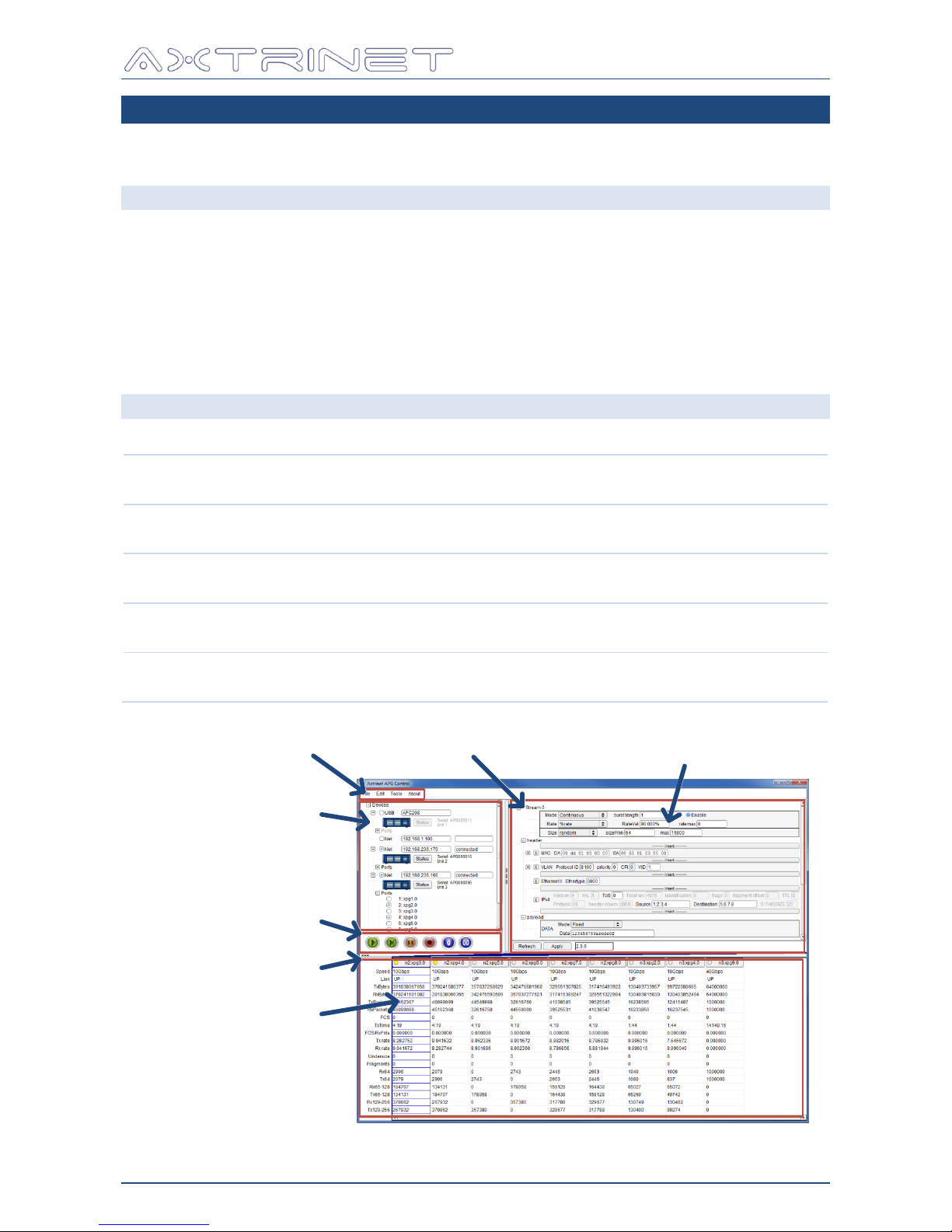
The APG Control Interface comprises 5 areas:
Menu Bar
APG Control Interface configuration and settings.
See Section 6.3
Connection Panel
Open/Close management connections to the packet generator units.
See Section 6.4
Stream Configuration
Panel
Port Stream Configuration
See Section 6.5
Control Panel
Start/Stop packet generator and clear counters
See Section 6.6
Counter Panel
Packet Generator counters and port control.
See Section 6.7
Horizontal SliderMenu Bar
Control Panel
Connection Panel
Stream Configuration
Panel
Counter Panel
Vertical Slider
Page 30
Ethernet Packet Generator
USER GUIDE
APG-UG-V2-1 30 8 February 2018
6.3 MENU BAR
File
Edit
Tools
About
Save
Save As
Load
Exit
Settings
Network Configuration
Counter Configuration
Upgrade Unit
6.3.1 File – Save
Saves the default Control Interface configuration:
IP Addresses of known units
Connection status
Counter configuration and Panel settings
Port visibility
The default configuration is used when the Control Interface starts.
6.3.2 File – Save As
Saves the current Control Interface configuration, including:
APG Control Interface layout, settings and port counters
Port and Stream configuration for all connected units
A "File Save As" window appears to select the save file name and location.
The saved configuration file has a .apg extension.
Saved configurations can be applied using the Load Configuration option.
6.3.3 File – Load
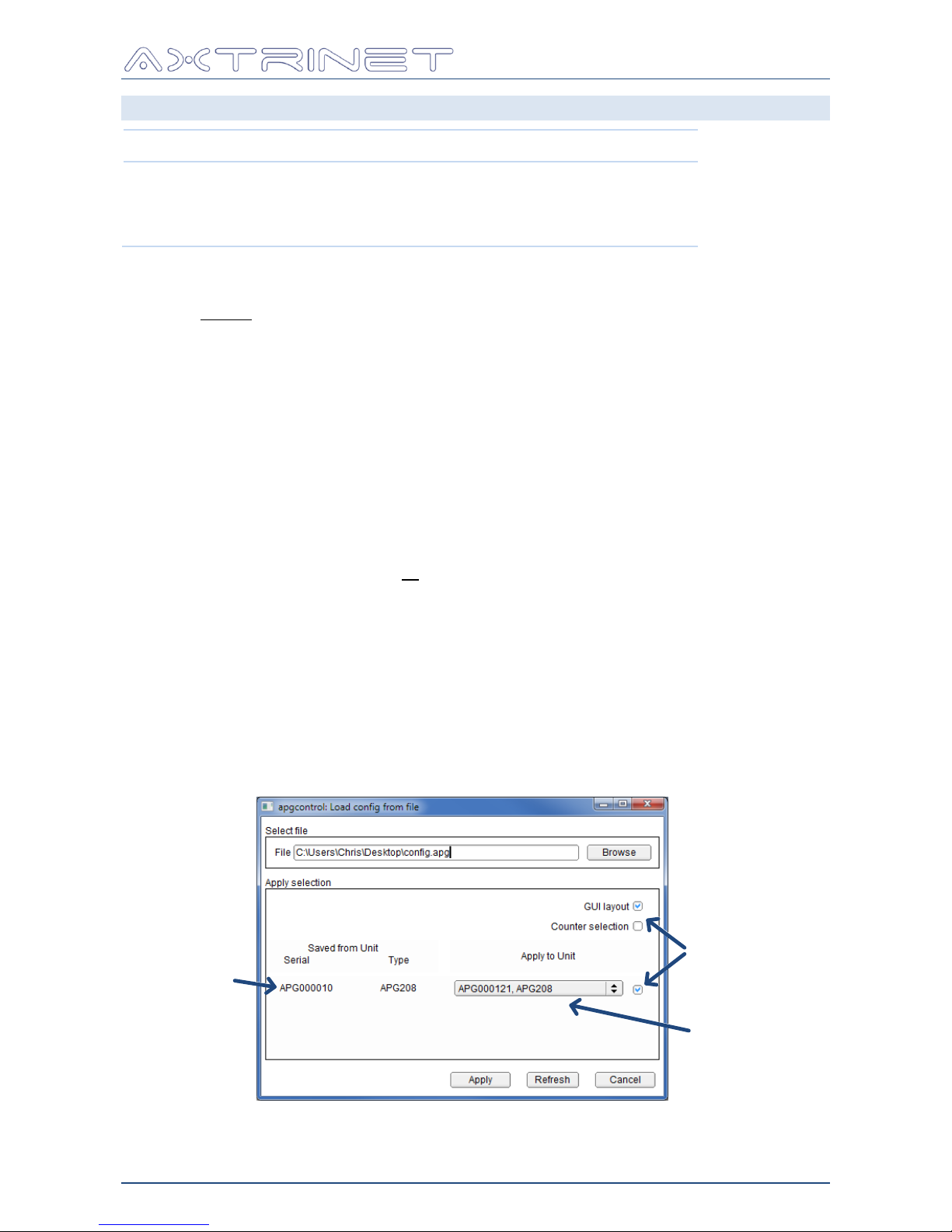
Loads a saved configuration file to selected unit(s).
The "Load Config from File" window appears to select the configuration file and select the data
to be applied to the current configuration.
Saved From
Unit List
Enable
Checkboxes
Apply To
Unit List
Page 31
Ethernet Packet Generator
USER GUIDE
APG-UG-V2-1 31 8 February 2018
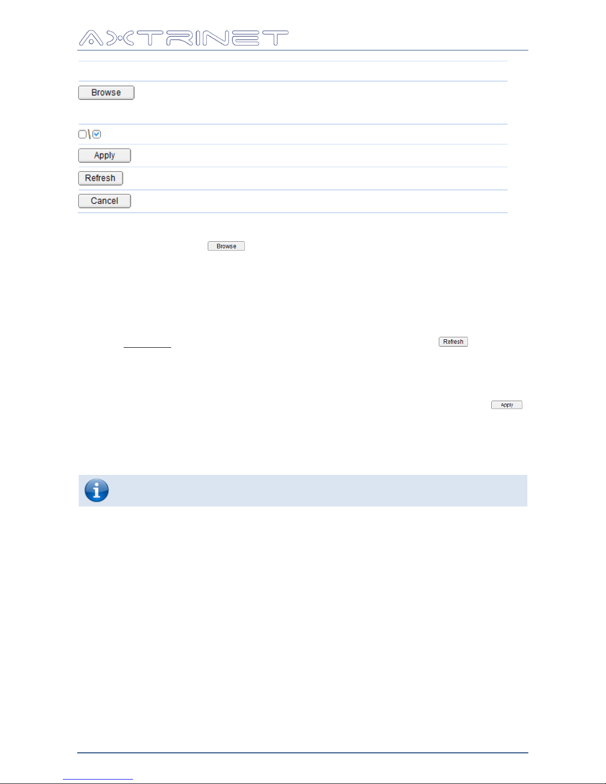
Button
Action
Opens the "File Load" window to select the load file name and location.
Alternatively the path and filename can be entered manually.
The path and filename default to the last used settings.
Disable/Enable Configuration change
Applies the saved configuration to the selected options
Refreshes the list of connected units
Closes the Load Configuration window without applying the changes.
Select the saved configuration file either by entering the path and filename (.apg extension)
manually or by clicking the button to open the File Selection window to select the
directory and filename.
Opening the selected file automatically parses the saved configuration where the contents are
analysed to determine how many units were included in the saved configuration.
The saved 'GUI Layout' and 'Counter Selection' will be applied if the corresponding checkbox is
enabled. The stream configuration is always applied.
A list of saved serial numbers and unit types are displayed, with a corresponding 'apply' list of
currently connected units. The connected unit list can be updated using the button.
The checkbox must be enabled to load the saved configuration onto the target unit.
The 'apply' unit does not have to be the same serial number or type, and saved ports will be
applied if the port exists on the target unit.
The configuration is applied to the APG Control Interface and connected units using the
button.
6.3.4 File - Exit
Closes the connections to APG units and close the Control Interface.
The APGs will continue to run and generate packets when the Control Interface is
not connected.
Page 32
Ethernet Packet Generator
USER GUIDE
APG-UG-V2-1 32 8 February 2018
6.3.5 Edit – Settings
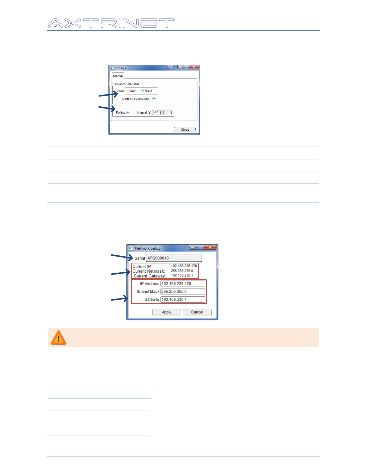
The APG Control Interface can be configured using the Settings option:
Formatting
Polling
Option
Description
Align
Align counter values LEFT or RIGHT
Comma Separators
Add 'thousand' separators to the counter values
Polling
Automatically poll the connected units every 'interval'
The polling interval is adjustable between 0.5 – 2 seconds.
6.3.6 Edit - Network Configuration
The network configuration is entered using the Network Configuration window:
Current Settings
New Settings
Unit
You may need to contact your Network Administrator to obtain the required
IP and Gateway Addresses
The serial number of the target unit is displayed. If more than one unit is connected through
the APG Control Interface, select the desired unit from the drop-down list of available unit
serial numbers.
The current IP settings of the selected unit are displayed.
The default settings are:
IP Address
192.168.1.100
Mask
255.255.255.0
Gateway
0.0.0.0
Page 33
Ethernet Packet Generator
USER GUIDE
APG-UG-V2-1 33 8 February 2018
Button
Action
Applies the Network Configuration changes to the unit.
Changing the Network Configuration while connected to the
unit over a network connection will immediately disconnect
the unit from the APG Control Interface. Open a new
connection with the new address to continue to manage the unit.
Closes the Network Configuration window without applying the changes.
6.3.7 Edit - Counter Configuration
Counters (eg TxPackets), status indicators (eg Speed) and calculated values (eg TxRate) can
be added or removed from the Counter Panel display list, and re-ordered within the display
list.
All counters are always active, so can be viewed or hidden without affecting the counter
values.
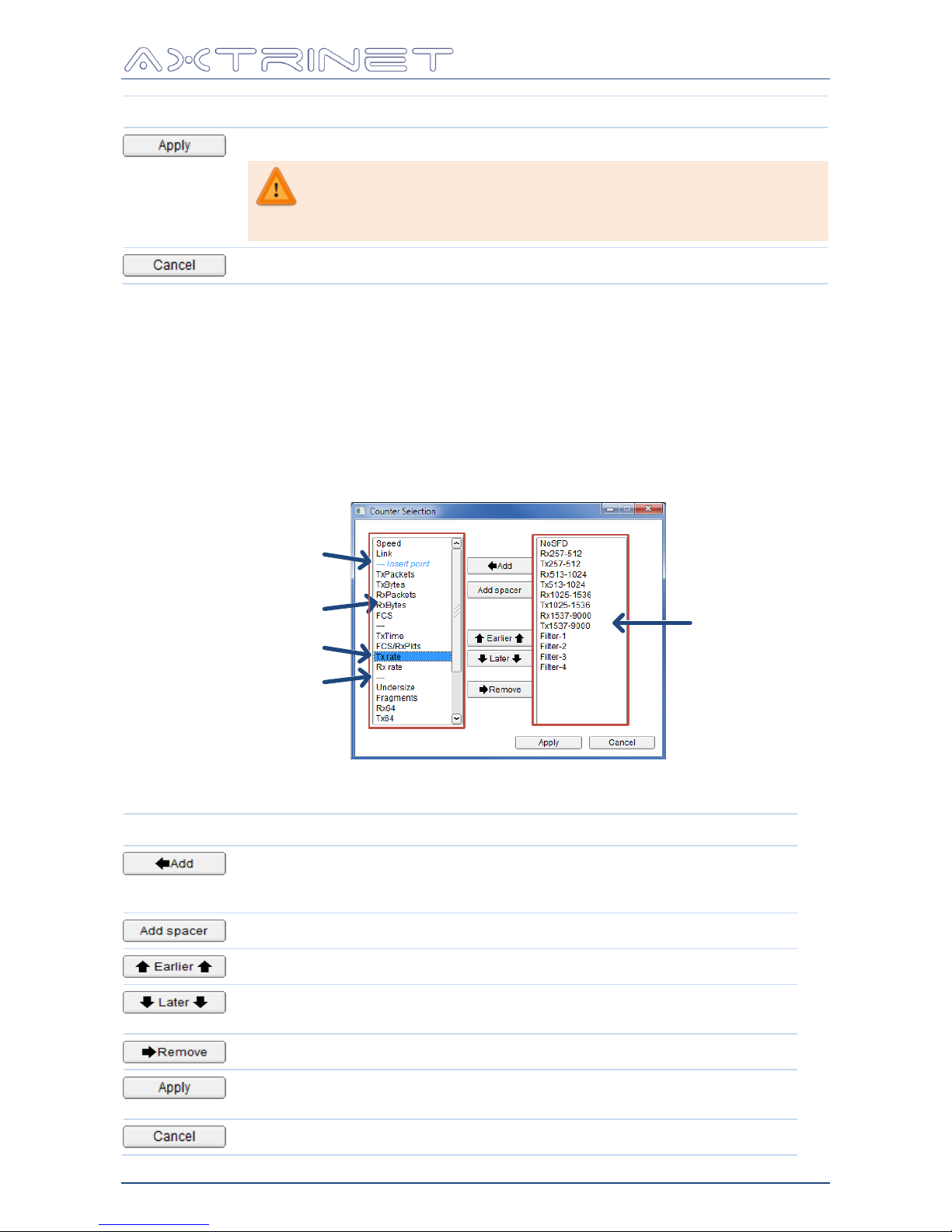
Counter management is performed using the Counter Configuration window:
Display Pane
Available
Counter
Pane
Separator
Selected Counter
Insert Point
The following control buttons are available:
Button
Action
Adds the selected counters to the DISPLAY COUNTER pane at the insert
point. The insert point can be moved UP and DOWN using the EARLIER
and LATER buttons.
Adds a spacer to the DISPLAY COUNTER pane at the insert point
Moves the currently selected counters in the DISPLAY COUNTER pane UP
Moves the currently selected counters in the DISPLAY COUNTER pane
DOWN
Removes the selected counters from the DISPLAY COUNTER pane
Applies the Counter Configuration changes to the Control Interface.
The displayed counters will update immediately.
Closes the Counter Configuration window.
Page 34

Ethernet Packet Generator
USER GUIDE
APG-UG-V2-1 34 8 February 2018
The following status indicators are available:
Status
Description
Speed
10Gbps or 40Gbps
Link
UP or DOWN
TxTime
Time in seconds since the START button was pressed
The following transmit counters are available:
Transmit
Description
TxBytes
Transmit Bytes
TxPackets
Transmit Packets
Tx64
Transmitted Packets with length equal to 64 bytes
Tx65-128
Transmitted Packets with length between 65 and 128 bytes
Tx129-256
Transmitted Packets with length between 129 and 256 bytes
Tx257-512
Transmitted Packets with length between 257 and 512 bytes
Tx513-1024
Transmitted Packets with length between 513 and 1024 bytes
Tx1025-1536
Transmitted Packets with length between 1025 and 1536 bytes
Tx1537-9000
Transmitted Packets with length between 1537 and 9000 bytes
Tx>9000
Transmitted Packets with length greater than 9000 bytes
The following receive counters are available:
Receive
Description
RxBytes
Receive Bytes
RxPackets
Valid Receive Packets
Rx64
Valid Receive Packets with length equal to 64 bytes
Rx65-128
Valid Receive Packets with length between 65 and 128 bytes
Rx129-256
Valid Receive Packets with length between 129 and 256 bytes
Rx257-512
Valid Receive Packets with length between 257 and 512 bytes
Rx513-1024
Valid Receive Packets with length between 513 and 1024 bytes
Rx1025-1536
Valid Receive Packets with length between 1025 and 1536 bytes
Rx1537-9000
Valid Receive Packets with length between 1537 and 9000 bytes
Rx>9000
Valid Receive Packets with length greater than 9000 bytes
Capture Filters are not supported in APG Control Interface Version 2.1
Page 35
Ethernet Packet Generator
USER GUIDE
APG-UG-V2-1 35 8 February 2018
The following error counters are available:
Errors
Description
FCS
Frame Checksum Errors Received
Undersize
Short packets (<64 bytes) with a valid SFD and FCS
Fragments
Packets without a valid SFD
NoSFD
Received Packet without a valid SFD
The following calculated values are available:
Calculated
Description
TxRate
Transmit Bit Rate in gigabits per second
Tx PPS
Transmit Paclets per Second
RxRate
Receive Bit Rate in gigabits per second
Rx PPS
Receive Packets per Second
FCS/RxPkts
FCS Error Rate (percentage)
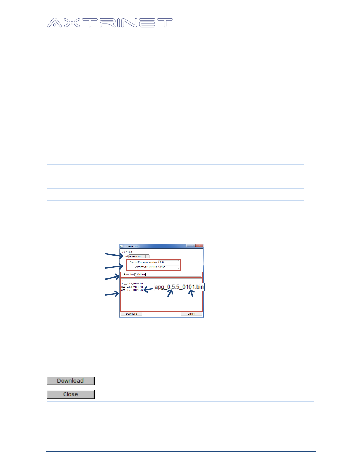
6.3.8 Tools – Upgrade Unit
The embedded software and FPGA firmware can be updated through the download window:
Current Versions
Download files
Unit
Directory Path
Software
Version
FPGA
Version
Select the target unit by the serial number from the dropdown list.
The current embedded software and FPGA firmware versions loaded on the unit are displayed.
Select the directory and download image from the file browser. The download image contains
both the embedded software and FPGA firmware images.
Option
Action
Applies the download file to the unit.
Closes the window without downloading new software.
Page 36
Ethernet Packet Generator
USER GUIDE
APG-UG-V2-1 36 8 February 2018
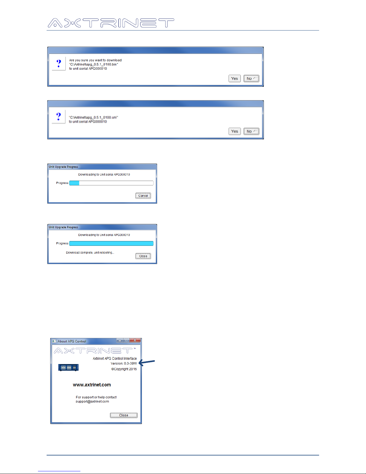
To continue the firmware download, click 'yes' when the confirmation window appears:
If an invalid file is selected, the following message is displayed:
The progress window appears while the image is downloaded to the unit:
Image download takes 2-3 minutes. When the download completes, the "download complete"
message is displayed and the unit reboots:
The PWR LED flashes amber while the new image is processed and saved into FLASH memory.
The re-FLASH process takes 3-4 minutes.
The unit then boots normally.
Total download, re-FLASH and reboot time is 6-8 minutes.
6.3.9 About
Displays the current APG Control Interface version:
APG Control Interface Version
Page 37
Ethernet Packet Generator
USER GUIDE
APG-UG-V2-1 37 8 February 2018
6.4 CONNECTION PANEL
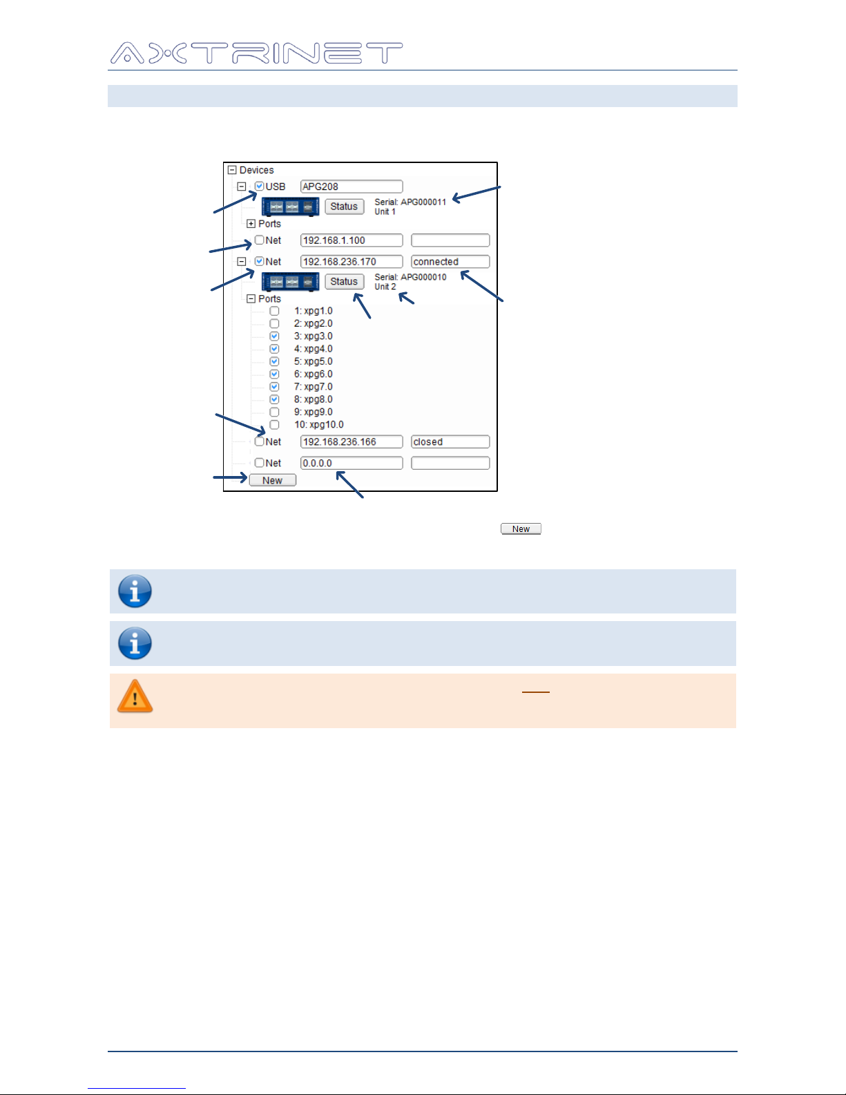
Connection to APG units using USB or Ethernet management interfaces is achieved through the
Connection Panel. Units using the USB interface will always be visible in the Connection Panel.
‘New’ IP Address field or Host Name
Connect
Checkbox
‘Managed’
Connection Status
New IP
Connection
Unit Status
USB Connection
Ethernet
Connection
Unit Serial Number
Unit ID
Connections to networked units must be defined using the button.
Click on the Connect Checkbox to toggle the management connection.
The USB interface does not display a connection status.
The Unit Status, serial number and ID are greyed out when not connected.
The visible ports are automatically added to the counter pane when the
management interface is connected.
If an attempt is made to connect using the USB and the Ethernet interfaces
on the same unit from the same APG Control interface, the second
attempted connection will fail.
Page 38
Ethernet Packet Generator
USER GUIDE
APG-UG-V2-1 38 8 February 2018
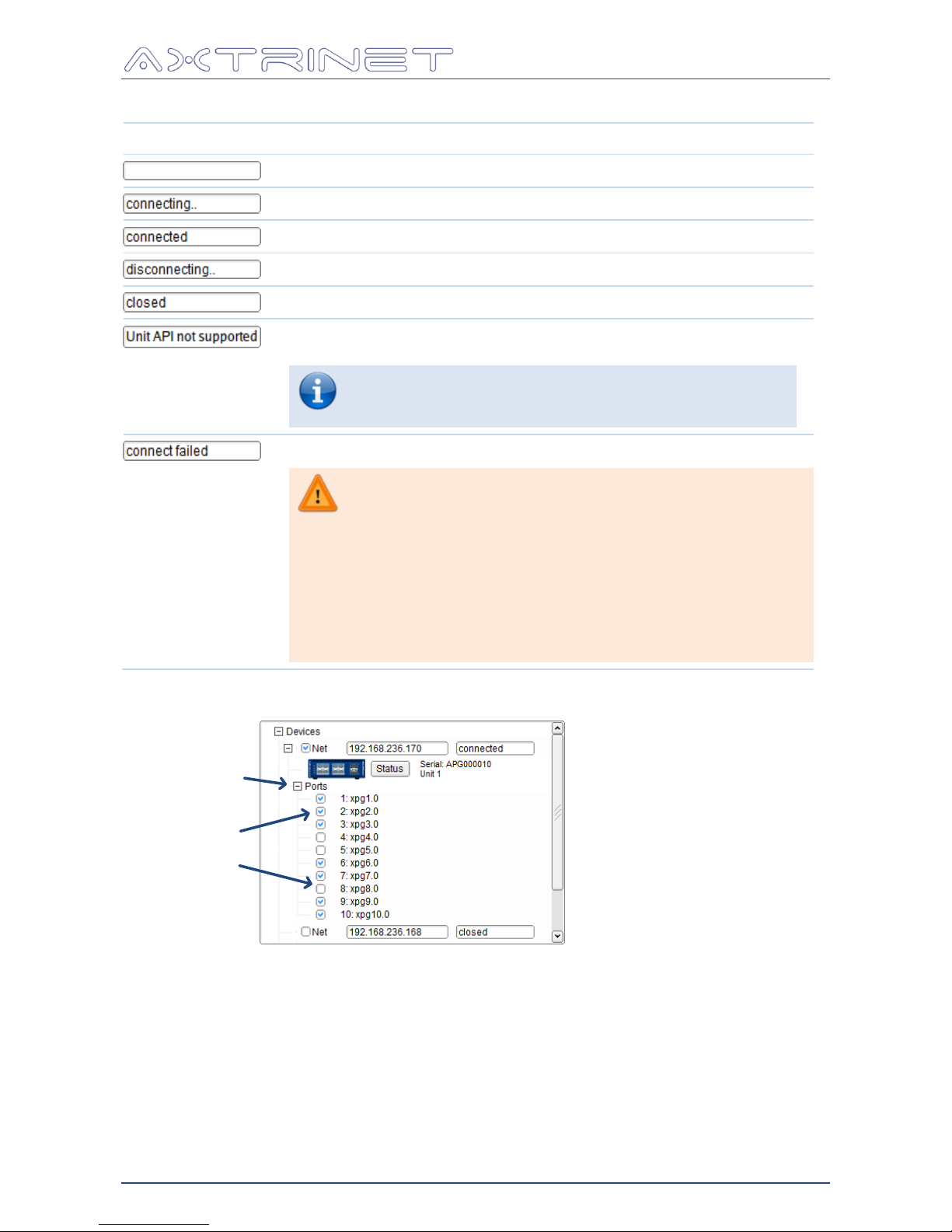
The Ethernet management status is displayed next to the IP address:
Status
Description
Connection not attempted during this APG Control Interface session
Connect Checkbox ticked, connecting to the APG
Connection successful and management interface active.
Connect Checkbox cleared, disconnecting from the APG
Management connection closed
If the Unit API is incompatible with the GUI API, the management
connection is refused.
Download the latest Embedded Software from
www.axtrinet.com/software.html
Then use the "Upgrade Unit" tool (Section 6.3.8)
Failed to connect to the APG management interface
If the connection fails, check:
IP Address
Can you ping the APG unit?
Is the APG unit connected to the network?
Is the IP address configured on the APG unit?
If trying to connect from a different subnet or
network, is the gateway address configured on the
APG unit?
The PORT EXPANDER opens the PORT VISIBILITY list.
Port Counters
Visible
Hidden
Port Expander
Checkboxes next to each port change the port visibility in the Counter Pane.
Page 39
Ethernet Packet Generator
USER GUIDE
APG-UG-V2-1 39 8 February 2018
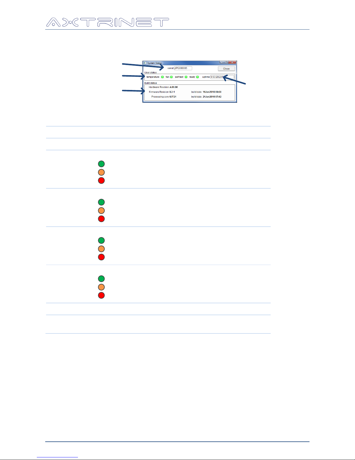
6.4.1 Status Window
Unit Status Summary
Serial Number
Up Time
Firmware Versions
The System Status summary displays the following information:
Option
Function
Serial Number
Serial number of the unit
Unit Status
TEMP:
Temperature OK
Temperature Warning – fan speed will increase
Over-Temperature – front panel disabled
FAN:
Fan OK
Fan is running faster than expected
Fan is running at full speed
SELF-TEST:
Self-Test passed
Self-Test running
Self-Test Failed (READY status will also be RED)
READY:
Unit OK and ready to generate Ethernet Traffic
Unit booting
Unit failed
Up Time
Time since the unit was turned on
Versions
Hardware, Embedded Software and Processing Core (FPGA)
versions and date codes.
Page 40
Ethernet Packet Generator
USER GUIDE
APG-UG-V2-1 40 8 February 2018
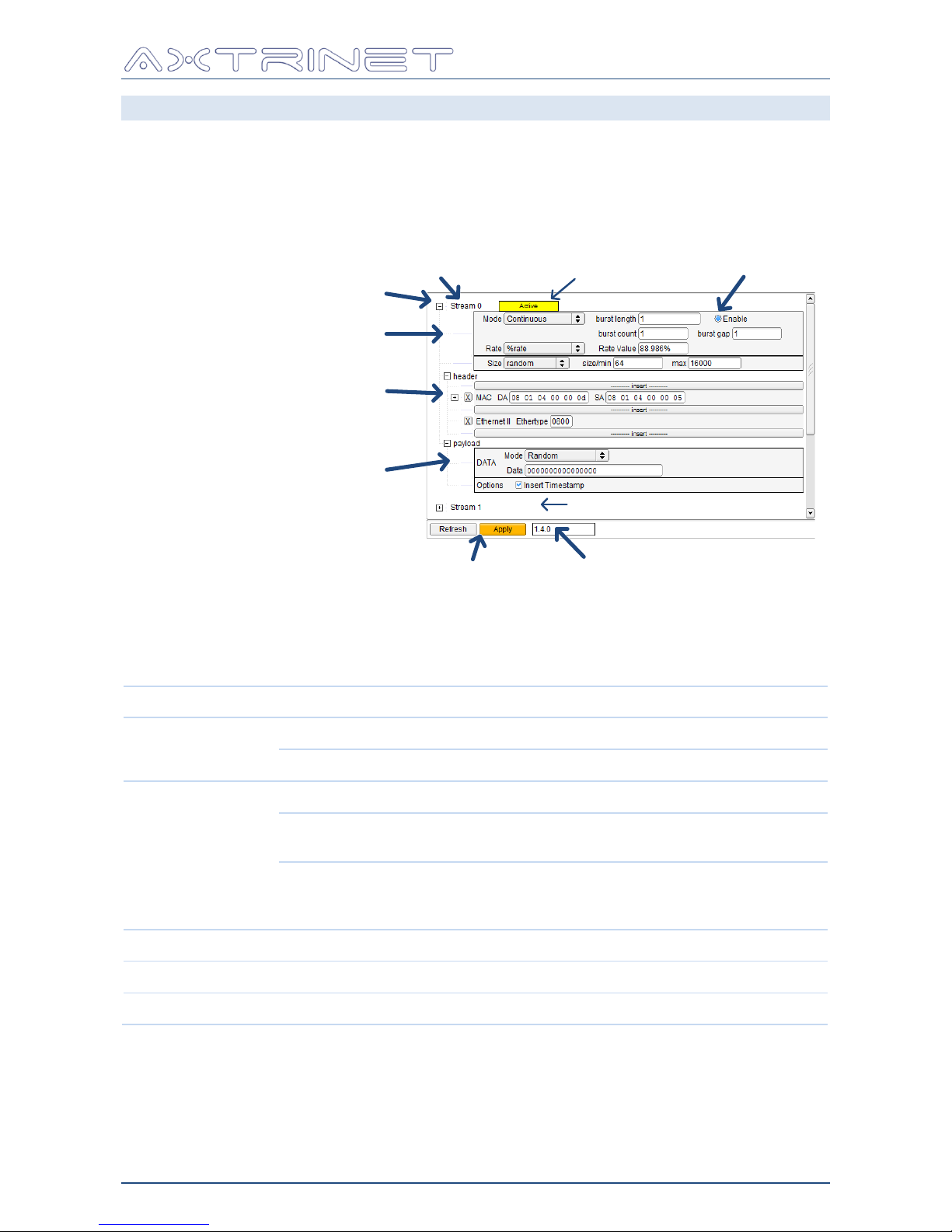
6.5 STREAM CONFIGURATION PANEL
Stream Configuration is defined in the Stream Configuration Panel.
Each port contains 8 parallel independent configurable Ethernet stream generators.
Each stream generates a controlled number of Ethernet frames at a controlled length and rate;
with a fixed header configuration, fixed or varying header contents, and a fixed or varying
payload.
Stream Label
Header Configuration Panel
Transmit Control Panel
Apply/Refresh
Payload Configuration Panel
Port Label
Enable
Stream Expander
Stream Enabled
Stream Disabled
6.5.1 Transmit Control
The stream transmit mode, rate and length are configured in the Transmit Control Panel.
Option
Setting
ENABLE
ON
Enable stream for port transmission.
OFF
Disable stream
MODE
CONTINUOUS
Transmit continuously until STOPPED or PAUSED
SINGLE BURST
Transmit BURST LENGTH packets, or until
STOPPED or PAUSED
MULTIPLE BURSTS
Transmit BURST LENGTH packets, wait BURST
GAP cycles, and repeat BURST COUNT times, or
until STOPPED or PAUSED
BURST LENGTH
Number of packets transmitted in a burst.
BURST GAP
Measured in μs
BURST COUNT
Number of bursts transmitted.
Page 41
Ethernet Packet Generator
USER GUIDE
APG-UG-V2-1 41 8 February 2018
Option
Setting
RATE
TXGAP
Inter-Packet Gap
At 10Gbps, RATE VAL defines the number of bytes
added to the 12-byte minimum IPG.
At 40Gbps, RATE VAL defined the number of 8-byte
words added to the 12-byte minimum IPG.
PACKET/SECOND
Packets transmitted per second
%RATE
Percentage of maximum packet rate.
RATE VAL
Value of the RATE setting.
The RATE VAL will remain the same value
if the RATE changes, which can lead to
unexpected results. Eg changing from an
TXGAP of 0 (max rate) to %RATE will stop
the stream.
SIZE
FIXED
Transmit packets of a single packet length only
INCREMENT
Transmit packets with incrementing packet length,
starting with SIZE MIN to SIZE MAX, wrapping to
SIZE MIN.
DECREMENT
Transmit packets with decrementing packet length,
starting with SIZE MAX to SIZE MIN, wrapping to
SIZE MAX.
RANDOM
Transmit packets with random packet length
between SIZE MAX and SIZE MIN
SIZE FIXED/MIN
Packet Length if SIZE is FIXED.
Minimum packet length for variable SIZE modes.
The minimum allowable packet length at
10Gbps is 13 bytes.
The minimum allowable packet length at
40Gbps is 37 bytes.
The minimum valid packet length is 64
bytes.
SIZE MAX
Maximum packet length for variable SIZE modes.
Not used if SIZE is FIXED.
The maximum packet length at 10Gbps
and 40Gbps is 16000 bytes.
Page 42
Ethernet Packet Generator
USER GUIDE
APG-UG-V2-1 42 8 February 2018
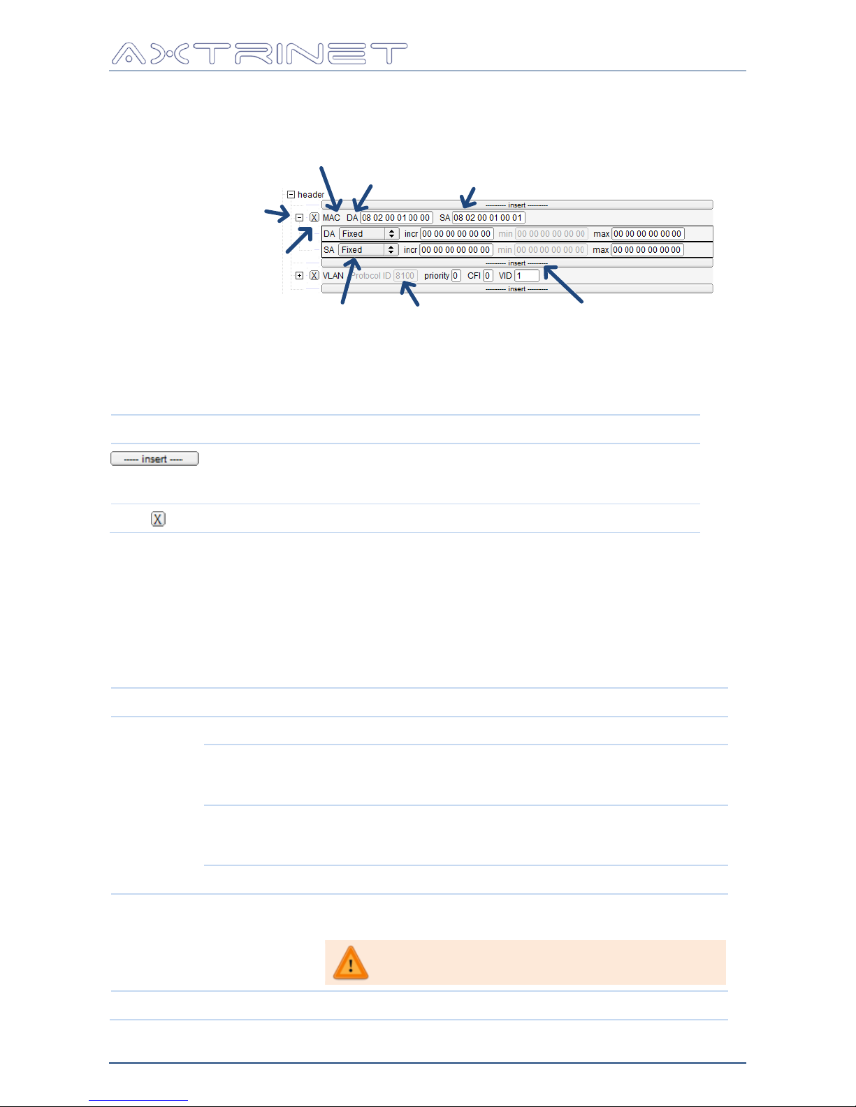
6.5.2 Header Configuration
The packet headers and contents are configured in the Header Configuration Panel.
Editable Field
Expand Header
Fixed Field Insert new header
Delete Header
Header Type
Field
Name
Variable Field
The available headers are extracted from an external configuration file when the APG Control
Interface starts. Header support is defined in the APG Header Guide [3].
Headers can be added or deleted:
Status
Description
Insert Header.
The 'next header' option depends on the previous header
eg: ETHERNET_II or VLAN headers can follow a MAC Header.
Delete Header
Editable fields are identified by a white editing box, and allow user values to be entered.
Fixed fields are greyed out, and cannot be changed.
Variable fields can be FIXED or INCREMENTING. A fixed field uses the field setting only.
Incrementing fields operate at byte level, not across the whole field. The incr value defines
the step, and max defines the maximum value.
6.5.3 Payload Configuration
Option
Setting
MODE
FIXED
Fixed, repeating DATA pattern
INCREMENT
Incrementing data byte, starting from the DATA byte,
wrapping from 0xFF to 0, repeating to the end of the
payload field.
DECREMENT
Decrementing data byte, starting from the DATA byte,
wrapping from 0 to 0xFF, repeating to the end of the
payload field.
RANDOM
Random byte generator
DATA
8 bytes (hex) eg: 00 11 22 33 44 55 66 77
Repeated to the end of the payload field
A DATA setting shorter than 8 bytes is extended
to 8 bytes with 00hex
OPTIONS
TIMESTAMP
Insert Timestamp checkbox
Page 43
Ethernet Packet Generator
USER GUIDE
APG-UG-V2-1 43 8 February 2018
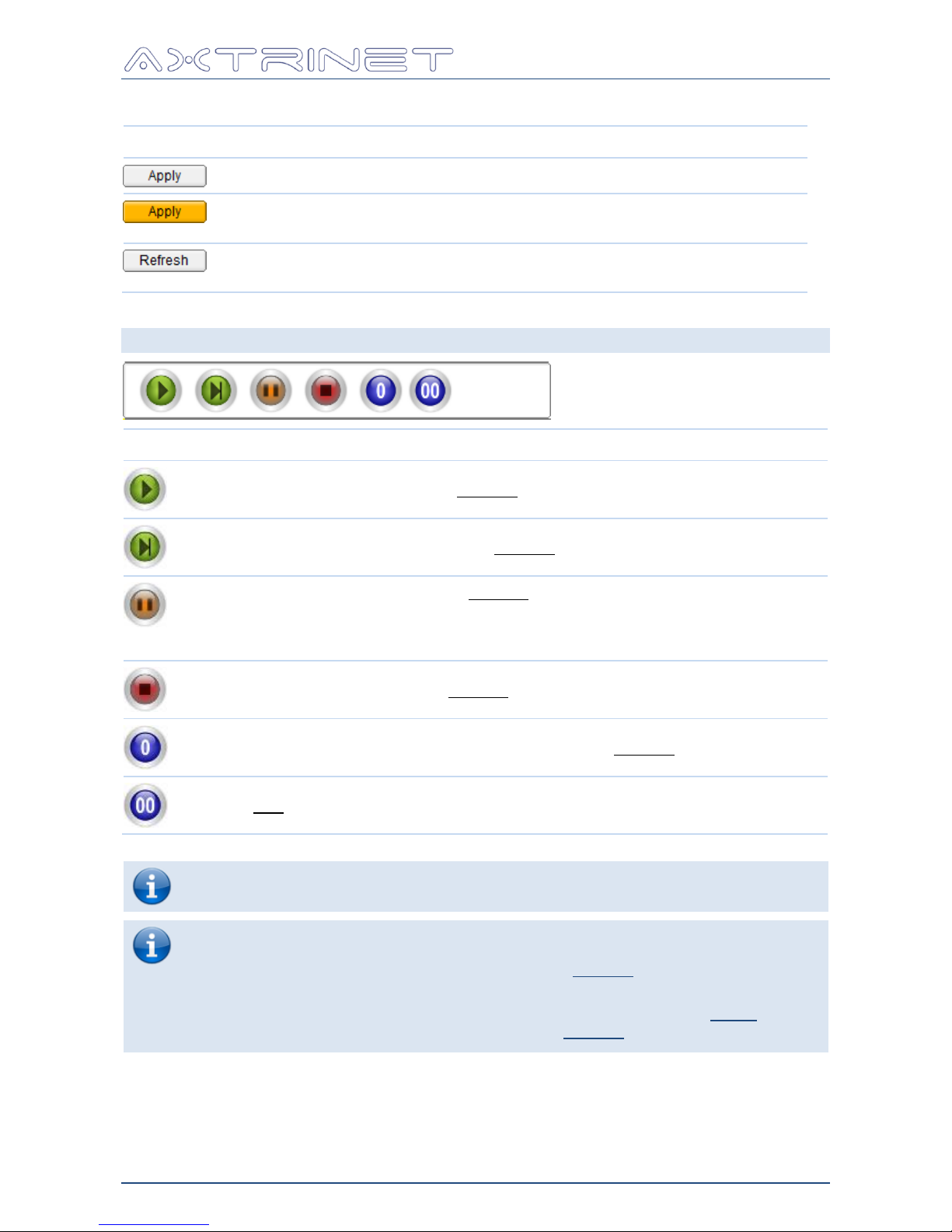
6.5.4 Apply/Refresh
Option
Action
Applies the configuration to the unit.
The button is highlighted orange when a configuration change has been made
but not applied.
Refresh cancels the configuration changes and reloads the configuration from
the unit.
6.6 CONTROL PANEL
Button
Action
START – Start transmitting on the selected ports.
STEP – Transmit a single packet on the selected ports
PAUSE – Pause transmission on the selected ports.
If the stream is configured to transmit a fixed length burst, the transmit count is
paused. Pressing the START button will continue the transmit burst.
STOP – Stop transmission on the selected ports.
CLEAR SELECTED COUNTERS – Clear counters on the selected ports only.
CLEAR ALL COUNTERS
To transmit a stream, the port, module and stream must be enabled and the BURST
LENGTH must be non-zero or continuous.
If all enabled streams configured on a port are in SINGLE BURST mode and have
finished sending packets, the packet transmission automatically stops. Pressing
START will load the stream configurations into the selected ports before starting
transmission.
If the port is transmitting packets, the STOP button must be pressed before the
START to load the stream configurations into the selected ports.
Page 44
Ethernet Packet Generator
USER GUIDE
APG-UG-V2-1 44 8 February 2018
6.7 COUNTER PANEL
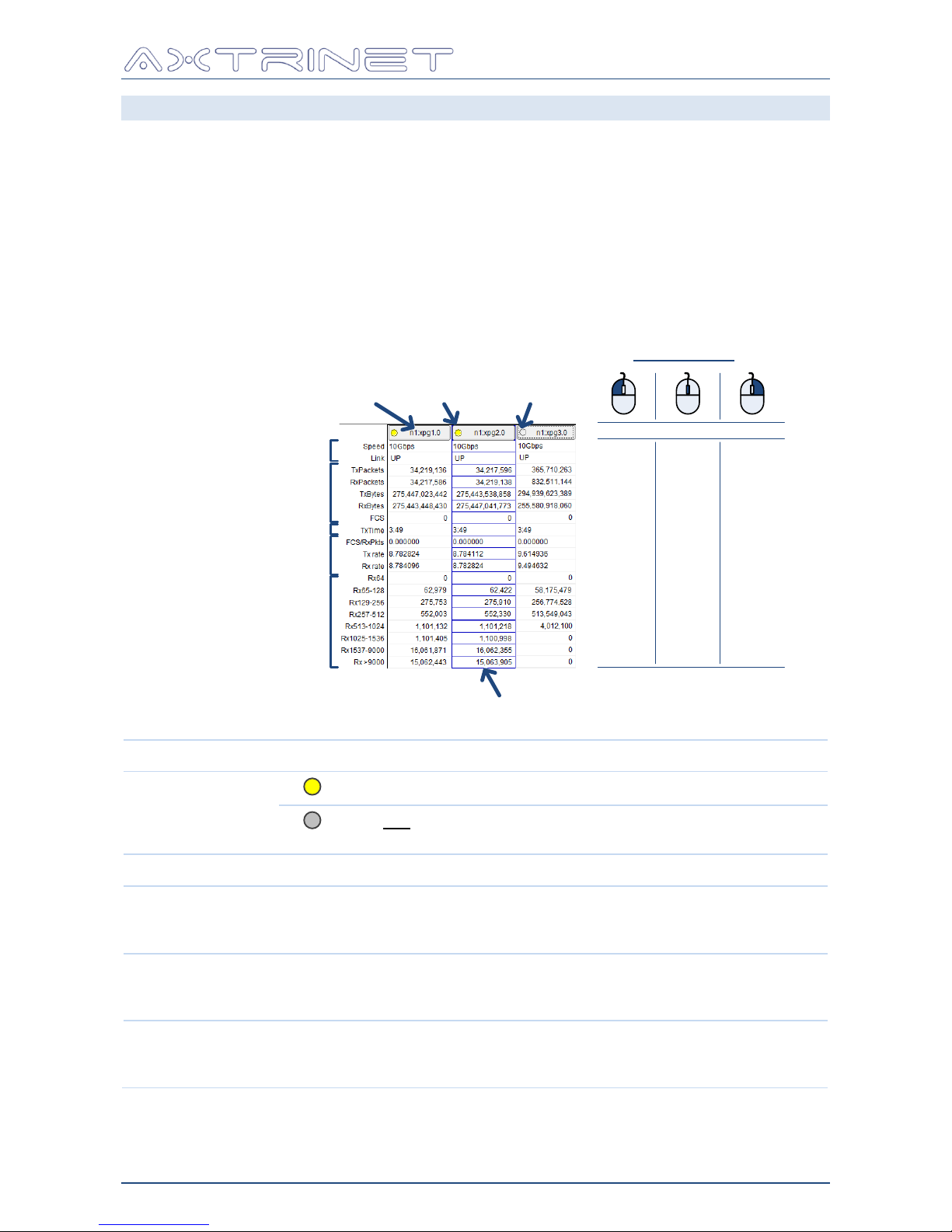
The Counter Panel provides access to:
Port control group selection
Port selection for Stream Configuration and Status Window
Hide Port display
Link Speed and Status display
Port transmit and receive counters and rates
The Counter Panel is configured using the Edit - Counter Configuration menu (Section 6.3.7),
or by right-clicking in the Counter Panel, then selecting 'Counter Configuration'.
Port
Label
Port Counters
Link Status
Port
Selected
Stream Selection
Port Not
Selected
Calculated Values
Mouse Click
Toggle port selection
Select
Port for
Stream
Config
Open
Port
Status
Window
Display
Port
Menu
Port Counters
Transmit Time
Option
Setting
Port Selector
Port selected for transmit control
Port not selected for transmit control
Click on the Port Label toggles the port selection
Speed
10Gbps or 40Gbps
Link Status
Link is UP or DOWN
If TRANSMIT ENABLE (Section 6.8.1.1) is not set (ie module
disabled), the Link Status is followed by (txd)
Port Counters
Displays the port transmit, receive and error counters.
Use Edit - Counter Configuration to select the displayed
counters (Section 6.3.7)
Calculated Values
Displays the calculated rate values
Use Edit - Counter Configuration to select the displayed
calculated values (Section 6.3.7)
Page 45
Ethernet Packet Generator
USER GUIDE
APG-UG-V2-1 45 8 February 2018
6.8 PORT STATUS WINDOW
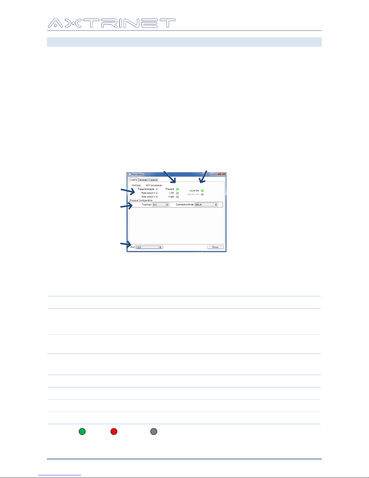
The Port Status window can be accessed in two ways:
Right-click in the counter pane to open the Port Menu, then select "Port Control", or
Middle-click in the counter pane
The Port Status window provides access to:
Module control and status signals
Module information
Packet Capture Summary (all ports)
6.8.1 Control Tab
Physical
Configuration
Module
Control
Module
Status
Link
Status
Port Selector
The contents of the Control Tab varies depending on the inserted module.
6.8.1.1 Module Control & Status
The Module Control bits can be set by the user:
Option
Function
Transmit Enable
Set to enable the transceiver
If not set (ie module disabled), the Link Status in the counter panel
(Section 6.7) is followed by (txd)
Rate Select 1/0
Rate Select bits are normally set for 10Gbps operation, but the actual
behaviour is defined by the transceiver vendor.
The Module Status bits are read-only, and set by the transceiver:
Status
Definition
Present
Transceiver detected in port
LOS
"Loss of Signal" flag
Fault
"Fault" flag
Where: Set Not Set Not Available
Page 46
Ethernet Packet Generator
USER GUIDE
APG-UG-V2-1 46 8 February 2018
The Link Status bits are set by the transceiver:
Status
Definition
Local Link
Displays the link status of the Packet Generator MAC to the link partner.
For fibre optic and direct attach cables, this is the end-to-end link status.
Where the module contains an additional active linking device, eg the
10GBase-T modules contain a PHY, the 'Local Link' is the MAC-to-PHY link
status.
Module Link
For fibre optic and direct attach cables, the 'Module Link' is not available.
Where the module contains an additional active linking device, eg the
10GBase-T modules contain a PHY, the 'Module Link' is the external link
status to the link partner.
6.8.1.2 Physical Configuration
Port Topology and Connection Mode are configured in the Physical Configuration settings to the
applicable port.
6.8.1.3 Module Configuration (optional)
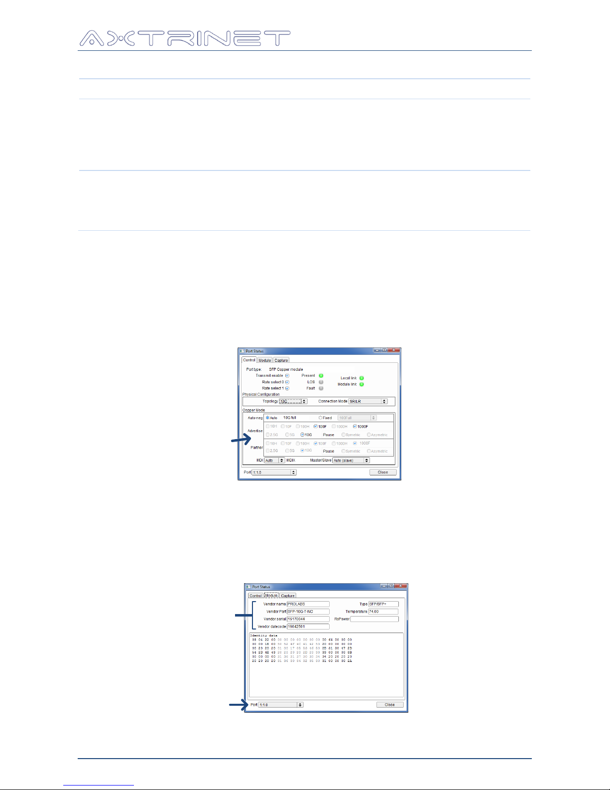
The Control Tab will display additional module configuration options if they are available, eg for
the 10GBase-T modules:
Module
Configuration
The 10GBase-T Configuration comprises the Auto-Negotiation and Advertised Capabilities
settings, the partner capabilities, and MDI/MDIX and Master/Slave configuration.
6.8.2 Module Tab
The Module tab shows the raw and decoded vendor fields from the inserted module.
Port Label
Raw
EEPROM
Data
Transceiver Details
Decoded from EEPROM Data
Page 47
Ethernet Packet Generator
USER GUIDE
APG-UG-V2-1 47 8 February 2018
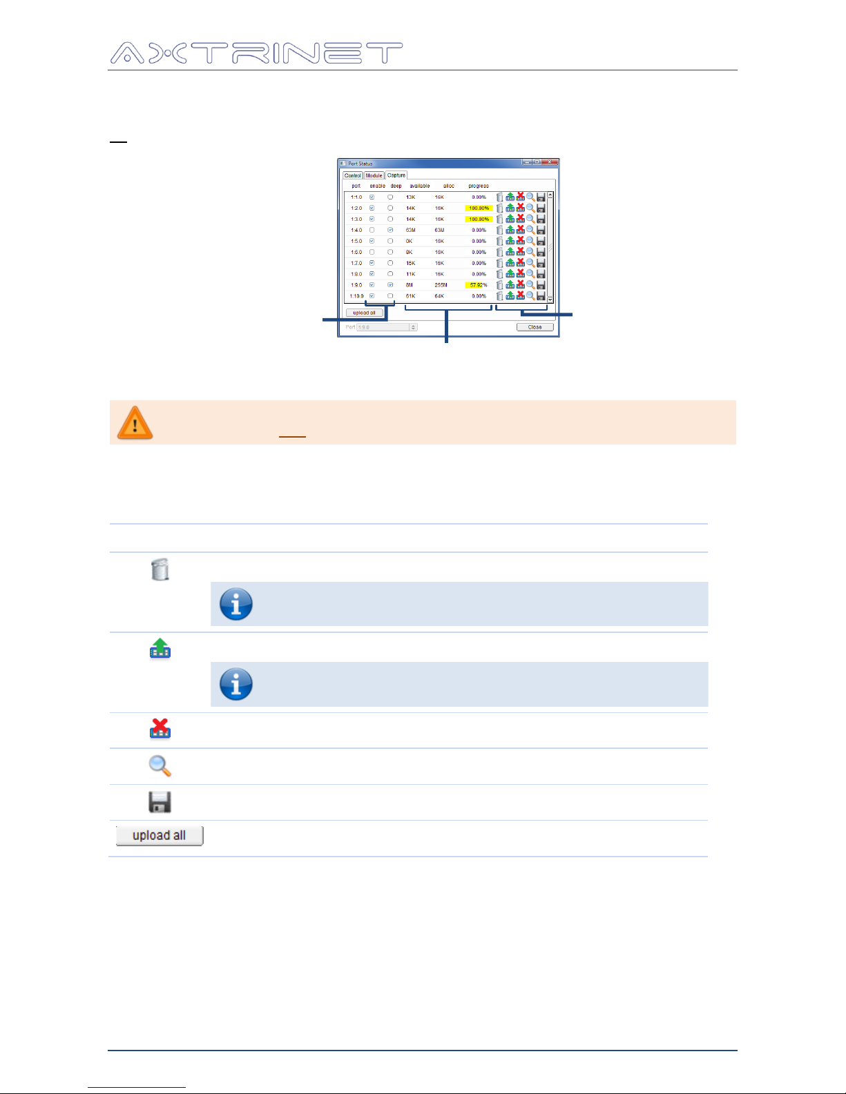
6.8.3 Capture Tab
The capture tab displays a summary of the capture buffer configuration, status and control for
all available ports.
Capture
Configuration
Status
Capture
Control
The capture configuration shows the ENABLE and DEEP setting for each port.
Although Deep Capture can be selected on more than one port, it can only
be enabled on one port in V2.1 Embedded Software.
The status values show the data captured in bytes (available), buffer space allocated in bytes
(alloc) and upload progress (yellow bar and %).
The port capture buffers can be controlled with the buttons:
Control
Function
Clear the packet capture buffer and restart the capture.
Click the VIE(w) button to display the captured packets.
Upload the Packet Data window with the latest captured data.
Updating the Packet Data window without clearing the packet
capture buffer will reload the same captured packet data.
Stop the port capture
View the uploaded data in the Capture Data Display window (Section 6.9)
Save the captured port data to a PCAP file.
Uploads all captured port data.
Page 48
Ethernet Packet Generator
USER GUIDE
APG-UG-V2-1 48 8 February 2018
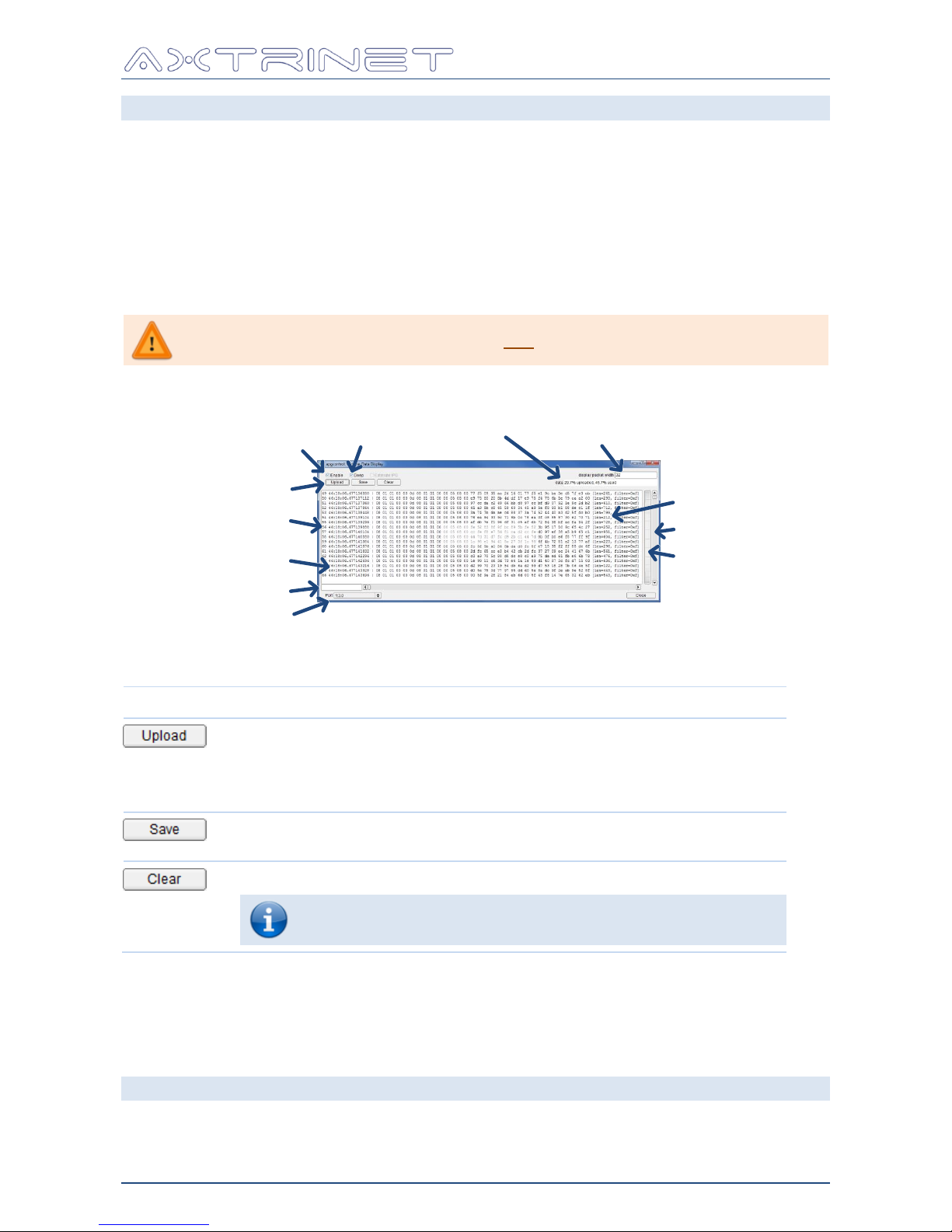
6.9 CAPTURE DATA DISPLAY
The Capture Data Display window is accessed either through the Port Status Capture Tab, or
by right-clicking in the counter panel to open the Port Menu, then selecting 'Capture Buffer'.
Packet Capture can be enabled per port by selecting the ENABLE checkbox. When enabled,
the buffer captures continuously until full. Clearing the buffer deletes the captured packets,
and immediately starts a new capture.
Each port has a 64KB capture buffer to store a few packets (depending on packet length)
which is useful for analysing single step behaviour or rare events. Alternatively, access to the
1GB shared extended packet capture can be enabled by selecting the DEEP checkbox, to store
large packet streams. The 64KB buffer is disabled when the deep packet capture is enabled.
Deep Capture can only be enabled on one port in V2.1 Embedded Software.
Display Packet
Width
Enable Capture
Enable Deep
Capture
Packet ID
Packet Data
Packet Length
Buffer Control
Upload
Status
Port Selector
Byte number
Coarse Slider
Fine Slider
The buffer control is performed with the following buttons:
Control
Function
Update with the latest captured packet data to the Capture Data Display
window.
The UPLOAD STATUS bar displays the Buffer Status (% used), and the
upload progress (% uploaded).
Saves the captured data to PCAP file.
Opens a FILE SAVE window to select save directory and filename.
Clear the packet capture buffer and restart the capture.
Click 'UPLOAD' button to display the captured packets.
The display window shows the 'Captured Packet Number', the transmit timestamp, the packet
data (showing 'Display Packet Width' bytes), and packet length.
6.10 SLIDERS
Vertical and horizontal slider allows adjustment of the panel sizes to suit viewing requirements.
Page 49

Ethernet Packet Generator
USER GUIDE
APG-UG-V2-1 49 8 February 2018
Xentech Solutions Ltd
Suite 6 Stanta Business Centre
3 Soothouse Spring
St Albans
AL3 6PF
United Kingdom
Tel: +44 (0)1727 867795
Email: [email protected]
 Loading...