

AXTON AXB25P Owner's Manual
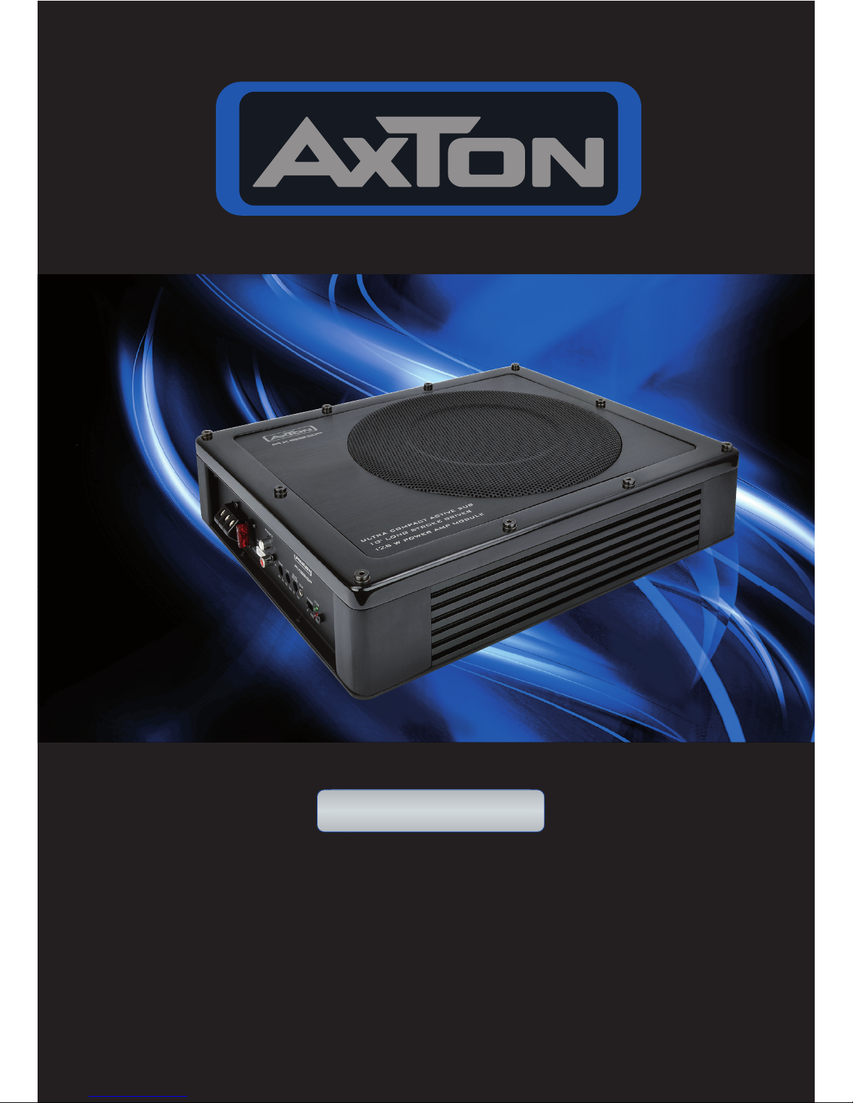
10"/25 CM ACTIVE
SUBWOOFER
AXB25P
OWNER‘S MANUAL/BEDIENUNGSANLEITUNG

– 2 –
DEAR CUSTOMER
Thank you and congratulations on your purchase of the AXTON AXB25P. This active subwoofer system exclusively uses very high quality parts and components. As with all highquality car audio components, professional installation is highly recommended. If you plan
on installing this active subwoofer by yourself, please read the following installation guide
carefully, before you attempt the installation. You should retain this manual, the packing and
the purchasing receipt for future reference. For any further information about mounting, connecting or adjusting this subwoofer system, please contact your AXTON dealer.
UNPACKING THE SYSTEM
Carefully remove all parts from the giftbox and check whether they are in good undamaged
condition, and match with the set contents listed below:
nAXB25P active subwoofer
nBass boost remote control
n5-wire high level input plug
nMounting clamps
nSet of mounting screws
nOwner‘s manual
Please contact your authorized AXTON dealer, if the content of this set is incomplete,
or parts of it show signs of transport damage.
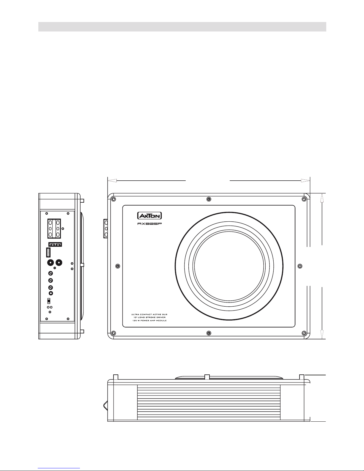
SPECIFICATIONS
n 10“/25 cm active trunk box subwoofer
n Frequency response: 25 Hz – 200 Hz
n85 W rms x 1 @ 4 ohms (<0.3% THD/14.4V)
n 125 W max. x 1 @ 4 ohms (<1.0% THD/14.4V)
n Darlingtonclass-A/Bamplier
n Variablelowpasslter:40Hz–200Hzwith12dB/Okt.
n Phase-shift: 0–180°
n Variable Bass-boost: 0–12 dB
n RCA, variable input sensitivity: 165 mV – 5 V
n External bass boost remote control
n Signal to noise ratio: > 90 dB
n Dimensions WxHxD: 280 x 80 x 340 mm
n Net Weight: 5.1 kg
– 3 –
ADDITIONAL SPECS
Supply Voltage 11 – 15V DC
Low Level Input 165 mV – 5 V
High Level Input 1.0 V – 10 V
Low Pass Filter 40 – 200 Hz
Fuse 10 A
280
80
340

– 4 –
SAFETY INSTRUCTIONS
1. This unit is designed to be used in a vehicle with a 12V battery and negative ground.
2. Before any wiring, always remove the negative terminal of the battery to prevent shortcircuiting. This is also the last lead to be (re-)connected.
3. Do not disassemble or alter the unit in any way, because that will also void your warranty.
Do not attempt to repair or to service the unit yourself, but contact an authorized AXTON
dealer instead.
4. Use only original accessories which are designed and manufactured for the unit,
otherwise you will risk to damage it. Install the unit according to the mounting manual and
use only the supplied mounting accessories. The forces of acceleration for accidents are
sometimes huge. Incorrect mounted units are a big risk for the driver and the passengers
of the car, during an accident.
5. Protect the unit from water and other liquids, which can enter the casing. A short circuit
or even fire could be the result.
6. Before you replace a defective fuse, try to find the cause for the short circuit. Please
pay attention to the cables of the power supply! If the short circuit doesn‘t result from a
failure of the power supply or wiring, you can replace the defective fuse with a new one
of identical value. If the short-circuit still exists, please contact an authorized AXTON
dealer.
7. Be careful not to drain the car battery while using the unit when the car engine is turned
off. Because the unit uses a considerable amount of energy and the battery will be
charged only while the engine is running, it might happen that the battery will discharge
to a point where it‘s not longer possible to start the engine.
8. If your car is parked in direct sunlight and there is a considerable rise in temperature
inside the car, allow the unit to cool off before operation.
9. The amplifier module employs a protection circuit to protect the transistors and the
woofer if the amplifier malfunctions. The amplifier’s protection circuitry will shut-off the
amplifier in case of short-circuit, overload or DC offset at the speaker outputs or in case
of overheat. In case the cause for protection shut-off has been eliminated, the amplifier
will operate normally again (green LED ON/ Red LED OFF). Otherwise the amplifier will
continue to switch on and off!
10. Do not use the unit with a weak or old battery as its optimum performance depends on
a normal battery supply voltage.
11. Please pay attention to the volume inside your vehicle, because you are obliged to notice
exterior sounds like a police siren or you might face penalties in case of an accident or
even loose your insurance cover.
12. Do not operate the unit in any other way than described in this manual. Failure to follow
the instructions within this manual will void your warranty.

– 5 –
INTERFERENCE
n All advice on controls and adjustments is based on the assumption that you are
also thouroughly acquainted with all the requirements and features of the entire
audio equipment – especially the head-unit – connected to this amplifier!
All cables are sources of interference. The power cable and RCA audio cable are very
prone to interference; the remote cables far less. There is often interference caused by the
generator (buzzing or whining), ignition (crackling) or other car electronic parts. Most of
these problems can be eliminated by correct and careful wire rooting. In doing so, read the
following guidelines first:
n Use only a screened RCA interconnects for the wiring between RCA input of the amplifier
and line-outs of the head unit.
n Lay the signal and power cables separately with enough distance from one another and
also from each other wire harness in the car. The REM cable to the automatic amp remote
output of the radio can be laid together with the signal cables. Avoid ground loops by laying
the ground wiring of all components to a center point in a star-like way.
n You can find the best central point in measuring the voltage directly at the battery. Now
compare this voltage value with the chosen ground point and the (+) terminal of the
amplifier. lf the measured voltage offers less than 0.1 V difference you‘ve found the correct
central, which should be clean and uncorroded. Otherwise you have to look for another
point. You should measure with the ignition being switched on and additionally switched on
other electronics (rear window heating and lights). If there are noise pickups from external
electrical sources try to route the RCA interconnect with a different path to the active sub.
– 6 –
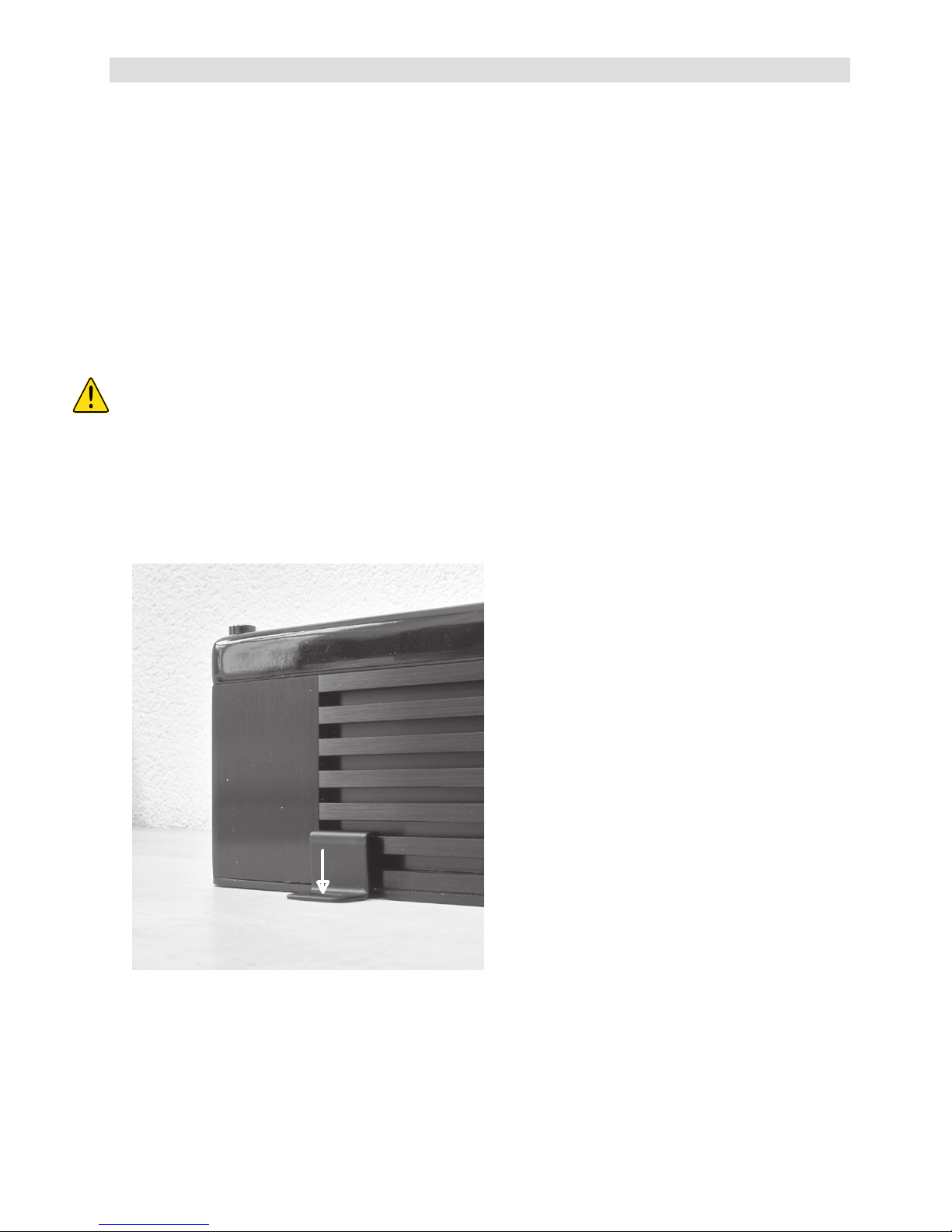
MOUNTING
n Note that the amp-module generates heat, so a well ventilated mounting place
is necessary or it will easily overheat.
n Keepthewireconnectionsasshortaspossible,withsufcientlength,inorderto
minimize power losses and provide a higher audio output of the system.
n For safety reasons route all power and speaker wiring by using the existing
wire channels.
n To minimize damage to the cables, take care that they do not pass through sharp
edged metal. Use rubber grommets were required.
n Lay all cables as far away as possible from the ignition cables, modules in the boot
and under the dashboard, as these create interference.
n Add a main fuse (60 A) to the (+) power cable in a distance of not more than
30 cm from the positive battery pole (re hazard!)
n Keep the length of the power cable as short as possible.
n The power cable should have at least a cable cross section of 10mm
2
(8 Gauge
AWG). Smaller cross sections are reducing the output power, are causing
distortions and may be triggering the overheat protection of the amp-module.
1. Position the mounting brackets.
2.Usethetappingscrewstoxthem.
 Loading...