

AXTON AXB25A, AXB20A Owner's Manual

AXB25A
OWNER‘S MANUAL/BEDIENUNGSANLEITUNG
10"/25 CM
ACTIVE
SUBWOOFER

– 2 – – 3 –
Dear Customer
Thank you and congratulations on your purchase of the AXTON AXB25A. This active subwoofer system exclusively uses very high quality parts and components. As with all highquality car audio components, professional installation is highly recommended. If you plan on
installing this active subwoofer by yourself, please read the following installation guide carefully, before you attempt the installation. You should retain this manual, the packing and the
purchasing receipt for future reference. For any further additional information about mounting,
connecting or adjusting this subwoofer system, please contact your AXTON dealer.
UNPACKING THE SYSTEM
Carefully remove all parts from the giftbox and check whether they are in good undamaged
condition, and match with the set contents listed below:
nAXB25A active subwoofer
nHigh level input connector
nOwner‘s manual
Please contact your authorized AXTON dealer, if the content of this set is incomplete,
or parts of it show signs of transport damage.
SPECIFICATIONS
■ 10” / 25 cm active subwoofer
■ Frequency response: 25 – 120 Hz
■ 70 W rms x 1 @ 4 ohms (< 1.0% THD / 14.4V)
■ 140 W max. x 1 @ 4 ohms (< 10% THD / 14.4V)
■ Class-D MOS-FET amplier
■ Variable lowpass lter: 60 Hz – 120 Hz with 12 dB/oct.
■ Variable phase shift control: 0 – 180°
■ Variable input sensitivity, RCA: 0.2 – 5 V
■ Variable input sensitivity, high-level: 1.0 – 8 V
■ Signal to noise ratio: > 85 dB
■ Dimensions WxHxD: 266 x 320 x 385 mm
■ Net Weight: 9.0 kg
DIMENSIONS
385
320 320
266
AXB25A
Side
Top
Front
266
AXB25A
266
109

– 4 – – 5 –
SAFETY INSTRUCTIONS
1. This unit is designed to be used in a vehicle with a 12V battery and negative ground.
2. Before any wiring, always remove the negative terminal of the battery to prevent shortcircuiting.
3. Do not disassemble or alter the unit in any way, because that will void your warranty. Do
not attempt to repair or to service the unit yourself, but contact an authorized AXTON
dealer instead.
4. Use only original accessories which are designed and manufactured for the unit,
otherwise you will risk damage. Install the unit according to the mounting manual and
use only the supplied mounting accessories. The forces of acceleration for accidents are
sometimes huge. Heavy objects may pose a risk for the driver and the passengers of the
car, during an accident.
5. Protect the unit from water and other liquids, which can enter the product. A short circuit
or even fire could result.
6. Before you replace a defective fuse, try to find the cause for the short circuit. Please
pay attention to the cables of the power supply! If the short circuit doesn‘t result from a
failure of the power supply or wiring, you can replace the defective fuse with a new one
of identical value. If the short-circuit still exists, please contact an authorized AXTON
dealer.
7. Be careful not to drain the car battery while using the unit when the engine is turned off.
Because the unit uses a considerable amount of energy and the battery will be charged
only while the engine is running, it might happen that the battery will discharge to a point,
where it‘s not longer possible to start the engine.
8. The amplifier module employs a protection circuit to protect the woofer from amplifier
malfunction. The amplifier’s protection circuitry will shut-off the amplifier in case of shortcircuit, overload DC offset and in case of overheat. In case the cause for protection
shut-off has been eliminated, the amplifier will operate normally again (green LED ON).
Otherwise the amplifier will continue to remain in protection mode.
9. Do not use the unit with a weak or old battery as its optimum performance depends on
a normal battery supply voltage of 12V.
10. Please pay attention to the music playback volume inside your vehicle, because you are
obliged to notice exterior sounds like a police siren or you might face penalties in case
of an accident or even loose your insurance coverage.
11 . Do not operate the unit in any other way than described in this manual. Failure to follow
the instructions within this manual will void your warranty.
WIRING & INTERFERENCE
n All advice on wiring, controls and adjustments are based on the assumption that
you are thouroughly acquainted with all the requirements and features of the entire
audio equipment connected to this powered subwoofer!
All cables are sources of interference. The RCA audio cables are prone to interference
pick-up. There is often interference caused by the alternator (buzzing or whining), ignition
(crackling) or other car electronics. Most of these problems can be eliminated by correct wire
routing. In doing so, read the following guidelines first:
n Use only double- or triple shielded RCA interconnects for the wiring between RCA input of
the amplifier and line-outs of the head unit.
n Lay the signal and power cables separately with enough distance from one another and
also from other wire harnesses in the car. The REM cable to the amp remote output of the
radio can be laid together with the signal cables. Avoid ground loops by laying the ground
wiring of all components to a center point in a star-like way.
n You can find the best central point in measuring the voltage directly at the battery. Compare
this voltage value with the chosen ground point and the (+) terminal of the amplifier. lf the
measured voltage offers less than 0.1 V difference you‘ve found the correct central, which
should be clean and uncorroded.
– 6 – – 7 –
MOUNTING & CONNECTIONS
Add a main fuse holder with appropriate fuse value to the (+) power cable
in a distance of not more than 30 cm from the positive battery pole.
n Keep the wire connections as short as possible, in order to minimize power losses and
preserve full power output of the system.
n To minimize damage to the cables, take care that they do not pass through sharp
edged metal. Use rubber grommets were required.
n Lay all cables as far away as possible from the ignition cables, modules in the boot
and under the dashboard, as these create interference.
n The power cable should have a cable cross section of 10 mm
2
(8 Gauge
AWG). Smaller cross sections are reducing the output power, are causing
distortions and may be triggering the overheat protection of the amp-module.
WIRING & CONNECTIONS
IMPORTANT:
Before any wiring, always remove the negative terminal of the battery to
prevent short-circuiting.
Connect this lead only after having completed and checked all other connections. The positive
power cable (+12V) must be connected directly to the positive terminal of the vehicle battery
to provide an adequate voltage source.
GROUND CONNECTION
The ground terminal (GND) connection is also critical to the correct operation of the amplier. Use a wire of the same gauge as the +12V cable and connect it between the ground
terminal (GND) of the amplier and a metal part of the vehicle close to the mounting location.
This wire should be as short as possible and any paint or rust at the grounding point should
be scraped away to provide a clean metal surface to which the end of the ground wire can
be screwed or bolted.
REMOTE TURN-ON CONNECTION
The amplier is turned on by applying +12V to the remote turn-on terminal (REM). The wire
lead to this terminal should be connected to the „Amp remote“ lead from the car stereo which
will provide the +12V only when the car stereo is turned on.
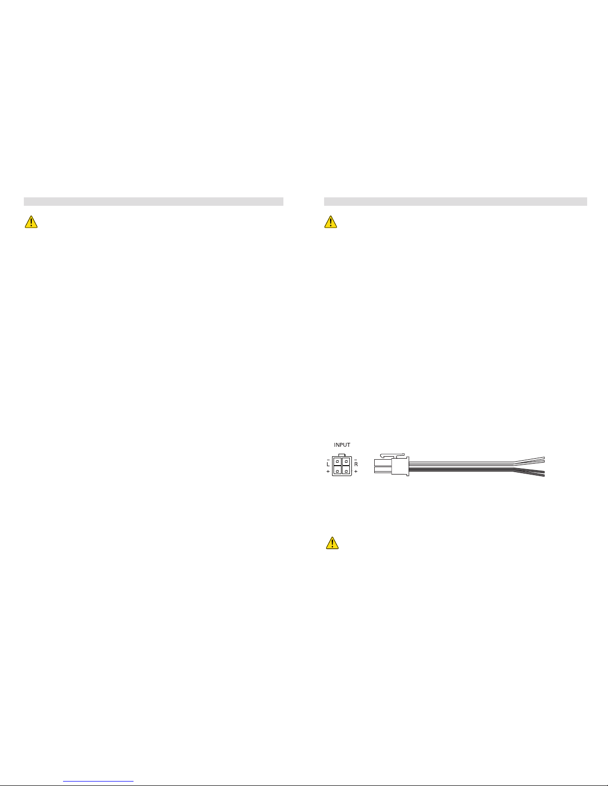
INPUT CONNECTIONS
This amplier features both high level and low-level (RCA) input capability. Use either the
low-level RCA or high-level inputs, not both. If the car stereo does not provide RCA outputs,
the amplier may be connected via the speaker (high-level) outputs from the car stereo. Wire
the speaker leads from the car stereo to the 4-pin adaptor harness as shown in the diagram
(shielded cables are not required for this application) and plug the connector into the high
input connector on the amplier.
NOTE:
When using the high-level input of your OE factory radio set ”Auto turn-on” to
ON. The AXB25A will cause a slight turn-on and turn-off noise in this mode, which is
completely normal.
Connect the wires to the loudspeaker leads in the vehicle, as
indicated on the amp-module.
 Loading...