

Page 1
1
Service Manual
Plus
MICROSPEED
Mcs-Plus-gb Ver.21/02/2002
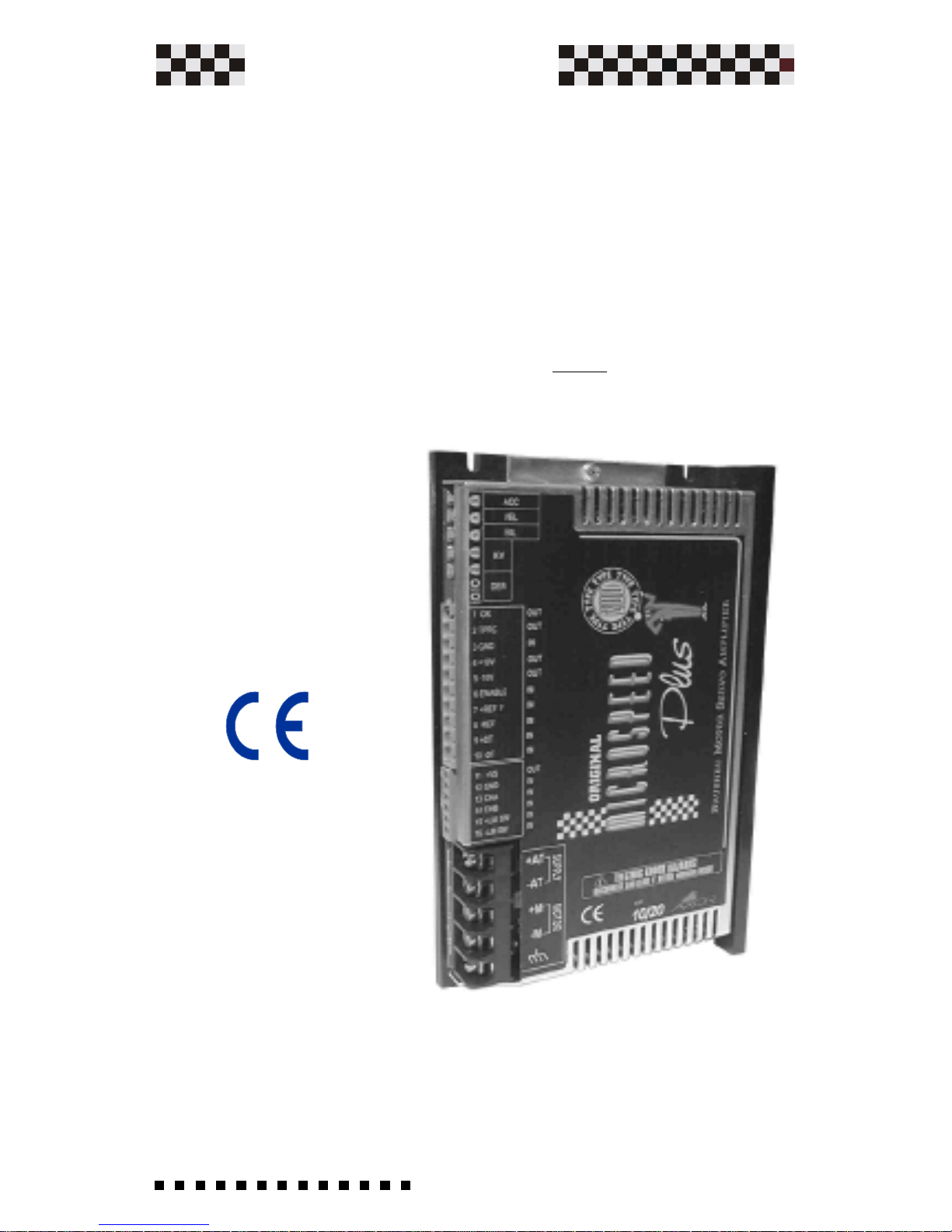
The MICROSPEED PLUS series of amplifiers are marked CE
because they conform to European Directives for
Electromagnetic Compatibility and Low Voltage.
This manual describes the mechanical and electrical
characteristics of the Microspeed Plus servoamplifier series.
It is important that the installation procedures are only
performed by qualified personnel in accordance with local
safety guidelines.
Whoever installs the equipment must follow all of the
technical instructions printed in this manual.
For more information, please contact AXOR's technical
department.
All rights reserved. Reproduction in whole or in part is prohibited without prior
written consent of the copyright owner. All specifications are subject to change
without prior written consent of the copyright owner. All specifications are subject
to change without prior notification.
Page 2

2
Service Manual
Plus
MICROSPEED
Index
Indice
1) Description
1.0 Security Standards ......................................................... 4-5
1.1 Introduction and Options ..............................................6-7
1.2 Technical Data ................................................................... 8
1.3 Microspeed Plus Description ......................................... 9
1.4 Drive Dimensions .......................................................10-11
1.5 Drive Label Description ................................................. 12
1.6 Connections...................................................................... 13
1.7 Signal Inputs and Outputs ........................................14-17
1.8 Power Supply Inputs and Outputs................................ 17
2) Indicator LEDs and Regulations
2.0 Potentiameter Adjustments ....................................... 18-19
2.1 Protections ........................................................................ 20
2.2 Indicator LEDs ................................................................. 21
3) Installation
3.0 Installation Notes ............................................................. 22
3.1 Ventilation .....................................................................22-23
3.2 Power Supply Construction and Rating .................24-28
3.3 Multiple Microspeed Connections .............................. 29
3.4 Ground and Shield Connections .............................30-31
3.5 Istructions for EMC Requirements .........................32-35
3.6 Example of Microspeed Plus Connections................ 36
3.7 Speed Reference ............................................................. 37
3.8 Current Reference........................................................... 38
3.9 Current Output Limitation .........................................39-40
3.10 Limit Switch Input +/-................................................... 41
3.11 Power Connections ....................................................... 42
Page 3

3
Service Manual
Plus
MICROSPEED
4) Start up procedures
4.0 Preliminary Checks......................................................... 43
4.1 Starting Procedures ...................................................43-44
5) Adjustments
5.0 Personalization and Settings ......................................... 45
5.1 Adjustments on Personalization Base ..................... 46-47
5.2 Solder Bridges ............................................................48-49
5.3 Speed Adjustments with D.T. Feedback ..................... 50
5.4 Speed Adjustments with Armature Feedback ......51-52
5.5 Speed Balance Adjustments (Offset)........................... 52
5.6 Nominal and Peak Current Adjustments .................... 53
5.7 Ramp Time Adjustments ................................................ 54
5.8 Dynamic Constant Adjustments...............................55-56
6) Troubleshooting
7.0 Troubleshooting ............................................................... 57
7) Option
7.1 Option Encoder .......................................................... 58-61
7.2 Option PWM+DIR......................................................62-63
Conformity Declaration ........................................................ 64
Index
Page 4
4
Service Manual
Plus
MICROSPEED
Danger Sign
This symbol is used where security directives should
be adhered to, where substantial risks are involved, and
where life endangerement or injury could occur.
Installers must scrupulously adhere to
prescribed directives and must communicate
them to the users.
W arning of Current being present
This symbol warns the user/installer to pay particular
attention to the presence of dangerous voltage (up to
270Vdc).
It's recommended to always remove drive from the
power supply net before working on the drive.
Warning
This symbol is present in all particularly important
points.
It's used where the intent is to highlight useful
considerations, prescriptions, indications, and the
correct execution procedures of every type of
intervention and prevention of damaging both systems
and drives.
General Security Directives
Along with what is prescribed in the manual, pay
attention to the security directives for prevention
of accidents and risks.
Always remove the power supply (disable) from both
the system and the drive prior to any type of intervention
on electric or mechanical parts.
1.0 Security standards
General Description
Page 5

5
Service Manual
Plus
MICROSPEED
The Microspeed Plus must only be installed by trained, qualified
and authorized personnel.
Any intervention or modifications effected on Microspeed Plus,
and their components or accessories, constitutes loss of
guarantee.
Isolate the drive from the power supply net before removing it
(by removing fuses or turning off the principal power switch).
The drive is equipped with electronic protections that disactivate
it in case of abnormalities, therefore the motor becomes
uncontrolled; this could cause the stoppage or idle motor ( for a
period determined by the type of system used).
In some cases the drive could restart automatically when the
reason for blockage is corrected.
In this case, some systems could be damaged or destroyed
endangering the welfare of personnel.
In this case the user must remove the drives' and systmes' power
supply so that the motor cannot automatically restart or prevent
such an event in the controller's program.
The Microspeed Plus terminals must always be grounded as per
the instructions in this manual.
General Description
Page 6

6
Service Manual
Plus
MICROSPEED
Capitolo 1
1.1 Introduction
General Description
The Microspeed Plus Servo Amplifier is a compact full DC four
quadrant drive. The (MOSFET)output power stage is controlled
by a 22 Khz PWM (Pulse With Modulation)signal that allows it t
drive small to medium sized brushless servo motors (up to 6Nm)
where high dynamic performance and precise speed is required.
The Microspeed only requires a single power supply to operate
and develops all needed voltages on board to make power supply
design easy and convenient.The input voltage is from 20 to 270
Vdc max "See Tecnical Data". (Chapter 3 describes how to design
a proper supply.)
Closing the velocity feedback loop to motor may be done in
several different ways to accommodate most applications. Three
types of velocity feedback are available with these drives. Refer
to Chapter 5 for the setup procedures that will effect your
application.
Feedback Types:
-Tachogenerator
-Armature.
-Encoder (Option)
-Pwm+Direction (Option)
Two inputs are present for the disabling of clockwise and counterclockwise motor rotation (+LM SW,-LM SW).
The possibility to completely adjust the Dynamic Constant exists
by inserting new values "as opposed to the standard mounted
values".
The insertion of various prearranged operational drive values
are easily realized by opening and closing solder points. The
intervention of drive protections are all visible with LEDs on the
front of the drive.
The nominal current, as well as peak current is adjusted through
resistance on the base.
The operating temperature is from 0 to +40 °C (32° to 104°F).
In accordance with the current size and model, supplemental
ventilation can be requested.
Page 7

7
Service Manual
Plus
MICROSPEED
Characteristic and Options
The speed feedback present on the Microspeed Plus are
highlighted.
Speed Feedback from Tachogenerator
Speed Feedback from Armature
Speed Feedback from Encoder
External Power Supply + Brake for plus .60
External Power Supply + Brake for plus .140
External Power Supply + Brake for plus .200
=Standard.
=Standard on sizes 14/28 ,20/40.
=Optional
General Description
Current Reference (torque mode)
Pwm+Dir command
Version with Booster
Limit switch
Page 8

8
Service Manual
Plus
MICROSPEED
1.2 Technical Data
MICROSPEED PLUS VOLTAGE
22Khz
32°-104°F (0°+40°C)
12°-158°F (-10°+70°C)
+/-5uV Degree F
+/-10Vdc
+/-7Vdc = (PK. curr.)
+5/+12Vdc ( 220 mA Max)
+/-10Vdc ( 4mA Max.)
250Khz Max.
2.5Khz
26.45 oz (750 gr.)
44.1 oz (1250 gr.)
10/95% non-condensing
--PWM frequency
--Operating Temperature
--Storage Temperature
--Drift
--Analog inputs
--Current Monitor (Imot)
--Encoder and Hall Signal
Power Supply (+V Optional)
--Auxiliary power supply
--Encoder Max.Freq. (Optional)
-- Band Width
--Weight Microb plus
--Weight Microb plus w/booster
--Humidity
TECHNICAL DATA CHARACTERISTICS
Size I nom. (A) I peak(A)
MICROSPEED PLUS CURRENT SIZES
1/2 +/-1 +/-2
2.5/5 +/- 2.5 +/- 5
6/12 +/- 8 +/- 16
10/20 +/- 10 +/- 20
14/28** +/- 14 +/- 28
20/40** +/- 20 +/- 40
* Minimum and maximum voltage. Tipical voltage are: 60Vdc,
140Vdc and 200Vdc.
Note a) The Microspeed plus 60 is produced only in sizes 14/28 e
20/40.
General Description
Microspeed 60 20 - 80 Vdc* Note a)
Microspeed 140 40 - 180 Vdc*
Microspeed 200 60 - 270 Vdc*
Page 9

9
Service Manual
Plus
MICROSPEED
1.3 Microspeed Plus Description
General Description
1 Calibration Area
2 Calibration Potentiometers
3 Hexadecimal Rotating Switch
4 10 poles 5.08 Phoenix Signal Terminals.
5 10 poles 5.08 Extractable Phoenix Terminals.
6 6 poles 3.81 Phoenix Signal Terminals.
7 6 poles 3.81 Extractable Phoenix Terminals.
8 Power Terminals AUGAT
9 Product Cover
10 Fixing screws
11 Serial Number
12 Product ID Label
13 Tacho Test point (Tachometric signal)
The power connector "AUGAT 6PCR-05" is used
on sizes 10/20-14/28 e 20/40A.
Power terminals "Phoenix GMSTB2,5/5-G" 7,62
for Microb sizes 1/2 2,5/5 6/12 .
Page 10

10
Service Manual
Plus
MICROSPEED
MICROSPEED PLUS
KV
DER
BIL
VEL
ACC
+M-M-AT
+AT
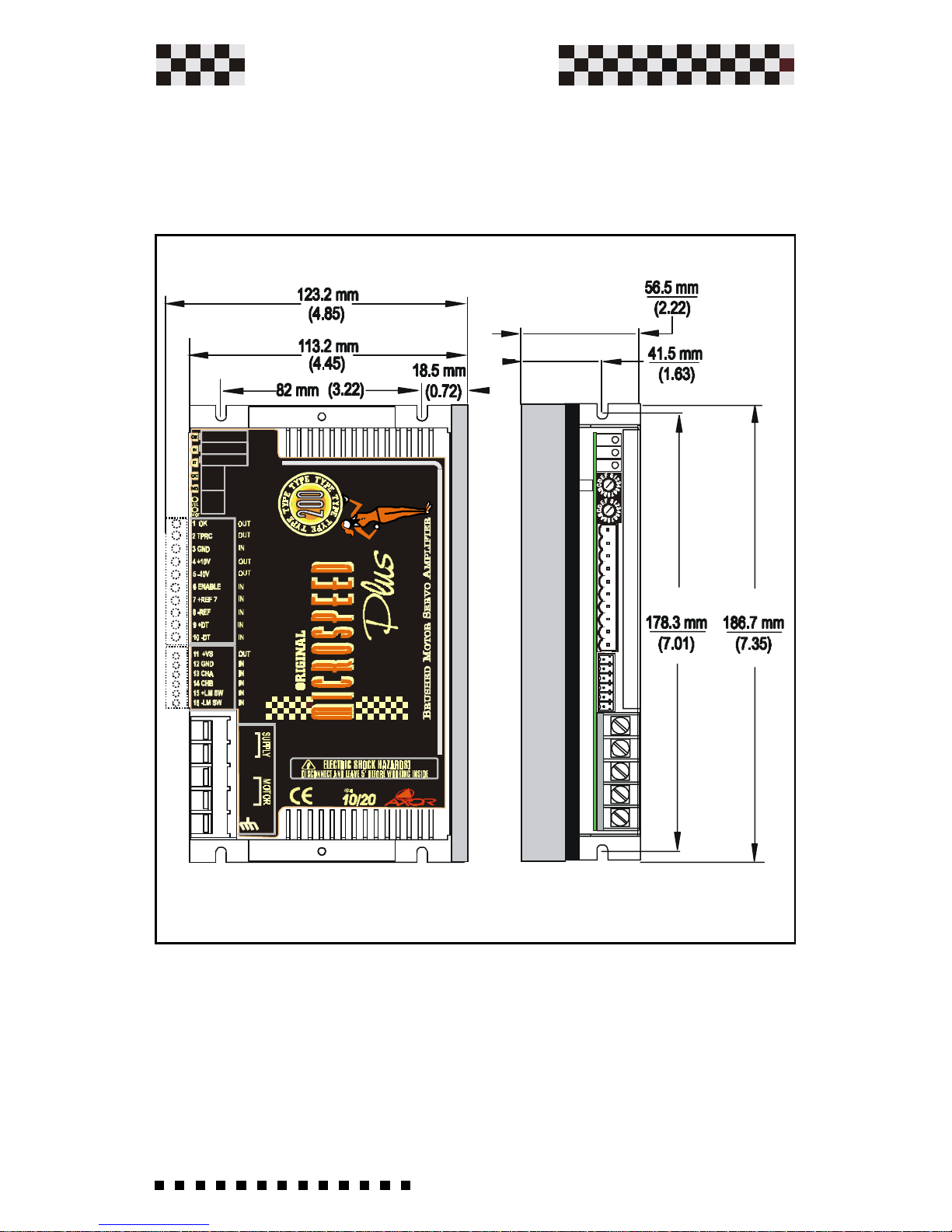
1.4 Drive Dimensions
NOTE: Dimensions mm ( INCHES)
General Description
Page 11
11
Service Manual
Plus
MICROSPEED
MICROSPEED PLUS WITH BOOSTER
KV
DER
BIL
VEL
ACC
+M-M-AT
+AT
General Description
NOTE: Dimensions mm ( INCHES)
Page 12
12
Service Manual
Plus
MICROSPEED
The Product Label is on all MICROSPEED PLUSDrives. The Label
printed above is a typical example. To identify the various options see
below: Product type and Identification:
ADJ is the identification of specific adjustments on the product for
specific motors. If the product is furnished Standard, the ADJ will show
the disbursed current.
ORD is AXOR's internal order number which relates to product
distribution. Always quote this number when asking for technical
assistance.
1.5 Drive Label Description (example)
General Description
Name: MCS PLUS
Model: 060-140-200
Size: 01/02- 2.5/5 -06/12 -10/20 -14/28 -20/40
Heatsink: N=Normal, B=Booster
Protection: S=Standard, T= Tropicalized
1000: Axor identification number
Feedback: T0= Tachogenerator, A0=Armature, E0=Encoder
Control mode: RD= Rifferential mode, I0= Demand current, PD=Pwm+Dir
ORDERING CODE
MCS PLUS-140-5/10-N-S-1000-T0-RD
ADJ 5/10A RA
Date 27/01/01 Ord. 365 /2001
Page 13

13
Service Manual
Plus
MICROSPEED
1.6 Connections
General Description
Page 14
14
Service Manual
Plus
MICROSPEED
2 TPRC(IN)
1 OK(OUT)
The following is the Signal Connector Description.
(10 Poles 5.08 Phoenix signal Terminals)
.
1.7 Signal inputs and outputs
General Description
Drive OK, Open Collector output 50mA Max. (Normally closed,
opens when in protection mode)
This signal can be used in 3 distinct modes:
A) Motor Current Limit Mode:
Soldering point S8 open S9 closed.
Applying a signal between zero and +10V you receive the
current limitation output from zero to max. drive size.
Ex:
Mcs Plus10/20A.......+5V limits the current to +/-10A.
Mcs Plus 14/28A.....+3.2V limits the current to +/-9A.
Note: The drive velocity loop remains active.
V ing=10 x I required
I peak
B) Motor Current Limit Mode:
S8 closed S9 open.
A motor current Limit mode connect an external resistor to
GND (pin 4) reduces the maximun current. Connect a 1/4W o
1/8W resistor between the TPRC and GND terminals.
A 47Kohm resistor reduces the current by 50%.
Note: The drive velocity loop remains active.
Page 15

15
Service Manual
Plus
MICROSPEED
3 GND
5 -10V(OUT)
6 ENABLE(IN)
4 +10V(OUT)
9 +DT(IN)
8 -REF(IN)
7 +REF(IN)
General Description
C) Current Reference (Torque Input):
S8 open S9 closed.
Range: +/- 10V, which corresponds to the drives peak current
output.
In this mode the velocity loop is automatically disabled .
Continued
Drive Common Ground. Corisponds to power supply's negative -AT input.
Power Supply +10Vdc 4mA Max.
Power Supply -10Vdc 4mA Max.
Drive Enable. Range +8Vdc to +24Vdc.
Reference Positive differential input. (Velocity command)
Reference Negative differential input. (Velocity command)
PositiveTacho input + (Connect to internal GND)
Negative Tacho input -
10 -DT(IN)
Page 16

16
Service Manual
Plus
MICROSPEED
15 +LM SW (IN)
12 GND
14 CHB(IN) (Optional)
13 CHA(IN) (Optional)
11 +V(OUT) Power supply encoder (Optional)
Note: The inputs 11-12-13-14, are enabled if the
Encoder Option is present.
General Description
Drive Common Ground. Corisponds to power supply's negative -AT input.
Encoder input Channel A
High logic level from +3,2V to +24Vdc.
Low logic level <1,5V.
+5Vdc 250mA Max.=(Solder bridge S13 closed).
+12Vdc 250mA Max.=(Solder bridge S13 open).
Encoder input Channel B
High logic level from +3,2V to +24Vdc.
Low logic level <1,5V.
Logic input that , disable with positive rotation (CW) of
motor.(Motor limit).
Such a function is enabled, by open soldering point S10 and
connecting a positive Voltage (between +5Vdc e +24Vdc)on
said input. When the voltage on said input is absent, motor
rotation blockage intervenes in a clockwise sense. See
Chapter 3.10
1.7a Signal inputs and outputs (6 poles)
Page 17

17
Service Manual
Plus
MICROSPEED
16 -LM SW (IN)
General Description
Logic input that , disable with positive rotation (CW) of
motor.(Motor limit).
Such a function is enabled, by open soldering point S10 and
connecting a positive Voltage (between +5Vdc e +24Vdc)on
said input. When the current on said input is absent, motor
rotation blockage intervenes in a counter-clockwise sense.
See Chapter 3.10
+AT (Input).
Positive continuous power supply.
+M (Output).
Motor connection +
GROUND(IN/OUT).
Ground drive
-M (Output).
Motor connection -
Negative Continuous power supply.
Common Zero Signal GND
-AT (Input).
1.8 Power Supply Inputs and Outputs
Page 18
18
Service Manual
Plus
MICROSPEED
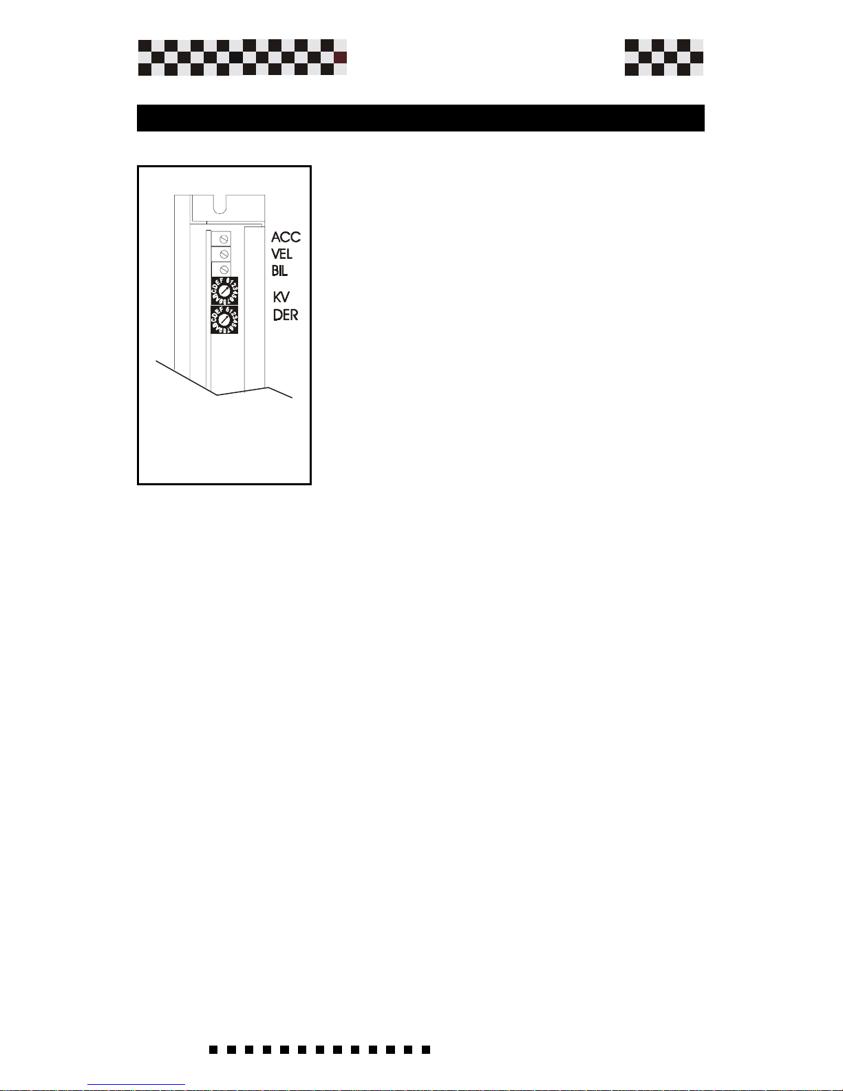
2.0 Potentiometer Adjustments
Adjustments
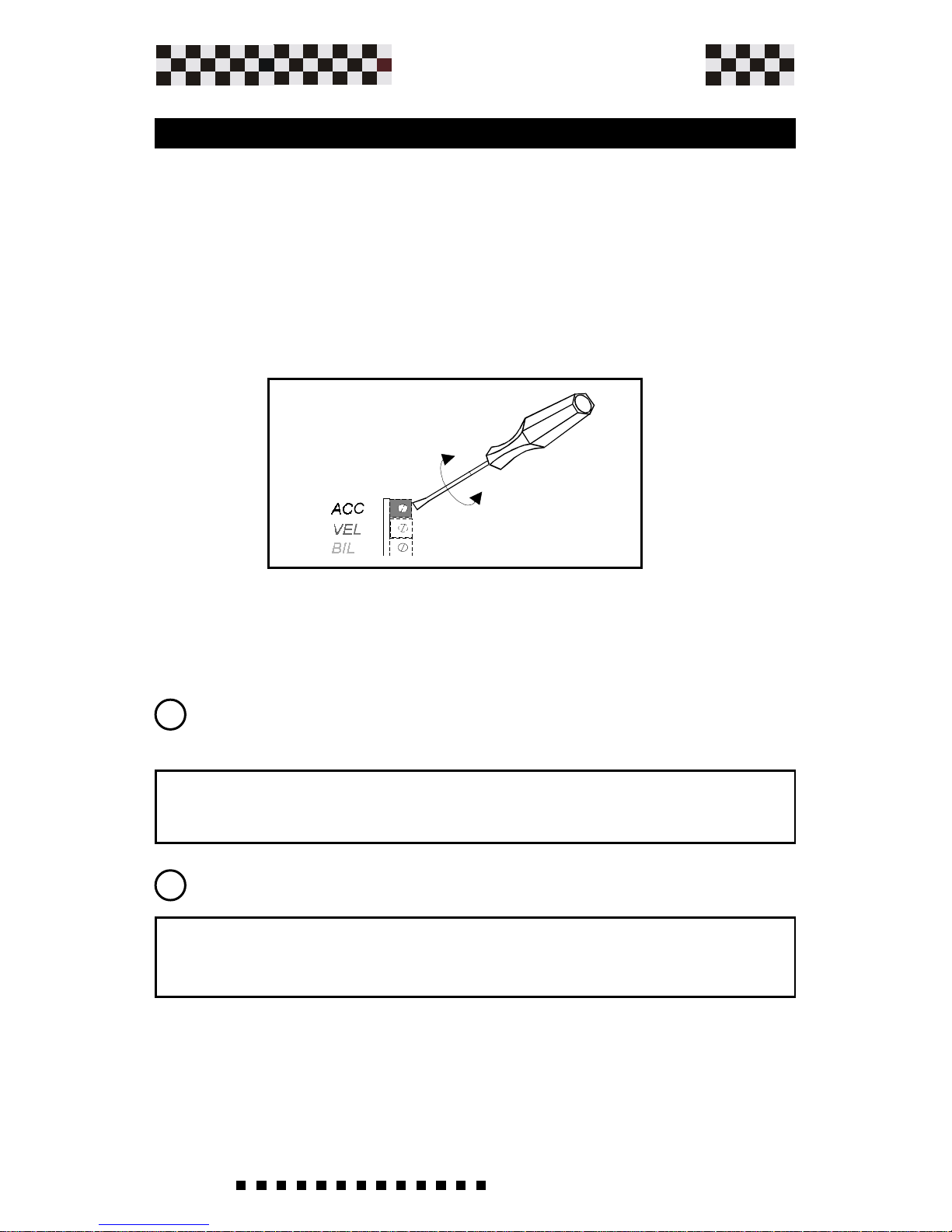
ACC
The solder bridges S2-S4 select the acc/
dec function (ramp). With this
potentiometer we can adjust the slope of
the acceleration and deceleration ramps.
Turning the potentiometer clockwise
(cw) increases the ramp time from 0,1
to 1 Sec (with 10 V reference).
VEL
Motor speed adjustment.Use this potentiometer to adjust the
maximum motor speed. Turn clockwise (cw) to increase the
motor speed and counter-clockwise (ccw) to reduce the motor
speed. The range of the adjustment is +/-20%.Note:
Potentiometer is disabled in torque mode.
BIL
Offset adjustment. Adjust this potentiometer to cancel any
motor speed when the Ref. input is 0 Vdc.
(Max ref. compensation +/- 200mV).
KV
Gain potentiometer.Use this potentiometer to increase or
decrease the dynamic behavior of the motor
With a clockwise turn (cw)we increase the gain of the PI
speed stage, therefore, improving the response.
Note: Potentiometer is disabled in torque mode.
It is also possible to increase or
decrease the pre-set max acc/dec ramp
time by opening solder bridge S3 and
inserting resistance RAMP.
(See chapter RAMP TIME ADJUSTMENT)
Page 19
19
Service Manual
Plus
MICROSPEED
DER
Derivative potentiometer. Turning this potentiometer clockwise
decreases motor overshoot.
Note: Potentiometer is disabled in torque mode.
Continued
Adjustments
NOTE:
On the Microspeed Plus the KV and DER
functions are constituted by Hexadecimal
rotating switch indentified with numbers from 0
to F.
With 0 you have the minimun function attainable,
and with F you receive the maximum.
WARNING: Increase the gain of KV and DER
in the progressive mode using the various
intermediate positions 1-2-3-4 etc.
Therefore, "turning counter-clockwise from
position 0 to position F" the motor could begin
vibrating.
Page 20
20
Service Manual
Plus
MICROSPEED
Microspeed 60 20 Min 80 Max
Microspeed 140 40 Min 180 Max
Microspeed 200 57 Min 270 Max
MICROSPEED PLUS VOLTAGE Vdc
2.1 Protections
The MICROSPEED PLUS is equipped with protection circuits
to safeguard both the motor and the drive, in case of faults
malfunctions.
All faults are indicated by LEDs on the front of the drive. (See
the next page).
The two types of interventions are Reversible and Irreversible.
----Reversible Protection Intervention:
The drive is automatically reset/restarted when the cause of
intervention has been corrected.
-Over Current limitation
-Over/under voltage input
----Irreversible Protection Intervention:
The drive is not reset/restarted. The power supply must be
removed and the cause of intervention eliminated, then the power
supply can be replaced. *Note: A mininum amount of time must
pass in order to ensure that the drive is completely off prior to
replacing the power supply.
-Short circuit
-Over temperature
-Missing or reversal tachogenerator/Encoder
Adjustments
Page 21
21
Service Manual
Plus
MICROSPEED
OKINSTOCMD
Adjustments
2.2 L.E.D. indicators
-OK (GREEN) Normally ON.
This
indicator shows that the drive is
operating correctly. If this LED is Off, it
is indicating at least one fault has been
activated. The faults that affect this LED
are:
--Over/Under input voltage.
--Over temperature, Over 104°F (40°C).
--Short Circuit, Outputs shorted to each
other or to ground.--Missing
Tachogenerator or Encoder
- IN (RED) Normally OFF.
This indicator is lit if the drive is in Over current mode.
- ST (RED) Normally OFF.
This indicator is lit when the
drives internal temperature reaches the max.value. Remove
power and wait for the drive to cool before re-applying power.
If operating temperatures are close to the Max operating temperature of the drive, a fan, heat sink or air conditioner may be
needed to remedy the problem.
- OC (RED) Normally OFF.
This indicator is lit if there is a
short circuit between the motor leads and/or ground. Remove
power and examine the motor connecting leads for shorts
before re-powering the drive.
- MD (RED) Normally OFF.
This indicator is lit for a loss of
tachogenerator/Encoder signal, or tachogenerator/Encoder
signal reverse.
FiveLEDs are located just in front of the
potentiometers and show the current state of the drive.
Page 22
22
Service Manual
Plus
MICROSPEED
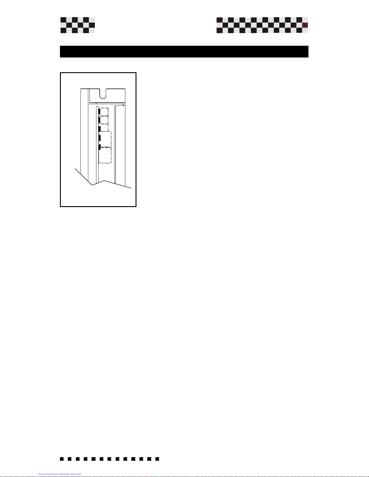
3.1 Ventilation
TheMicrospeed plus must be affixed vertically on the bottom to
guarantee efficient cooling. The drives working temperature
must be between +0° C and +40° C. Supplementary ventilation
may be requested in accordance to size. See the table below.
3.0 Installation Notes
The Microspeed Plus is predisposed for mounting inside a box.
The mounting hole measurements can be found in chapter 1.4
"Drive Dimensions". The Microspeed Plus must be fixed vertically
on the bottom of the box to guarantee efficient cooling by the
drive itself. The positioning inside the box must satisfy the
following dispositions:
• For best results from drive guarantee that inside the
electrical box a temperature between 0°C and +40°C with
humidity between 10% and 95% without condensation..
• Keep the drive from excessive mechanical vibrations in
the electrical box.
• During installation, insure avoiding any kind of metallic
residue from falling inside of the Microspeed Plus.
• Maintain a distance of 80mm from the heat source.
• The electrical box must have a predisposition for oppor-
tune air filtering holes or passageways.
Installation
Model 1/2 2.5/5 6/12 10/20 14/28 20/40
60 n.a n.a n.a n.a NV NV
140 N N N N NV NV
200 N N N NV NV BV
Page 23
23
Service Manual
Plus
MICROSPEED
MicroPower Plus Power Supply (optional)
Combination table of dissipators present on Microspeed Plus.
n.a = Unavailable size with Microspeed Plus.(Available with Microspeed Case
PM1)
N = Microspeed Plus with normal radiator (See Chapter 1.5)
B = Microspeed Plus with added radiator Booster (See
Chapter 1.4)
NV = Microspeed Plus + supplementary ventilation.
BV = Microspeed Plus with added radiator Booster + supplementary
ventilation.
Installation
Page 24
24
Service Manual
Plus
MICROSPEED
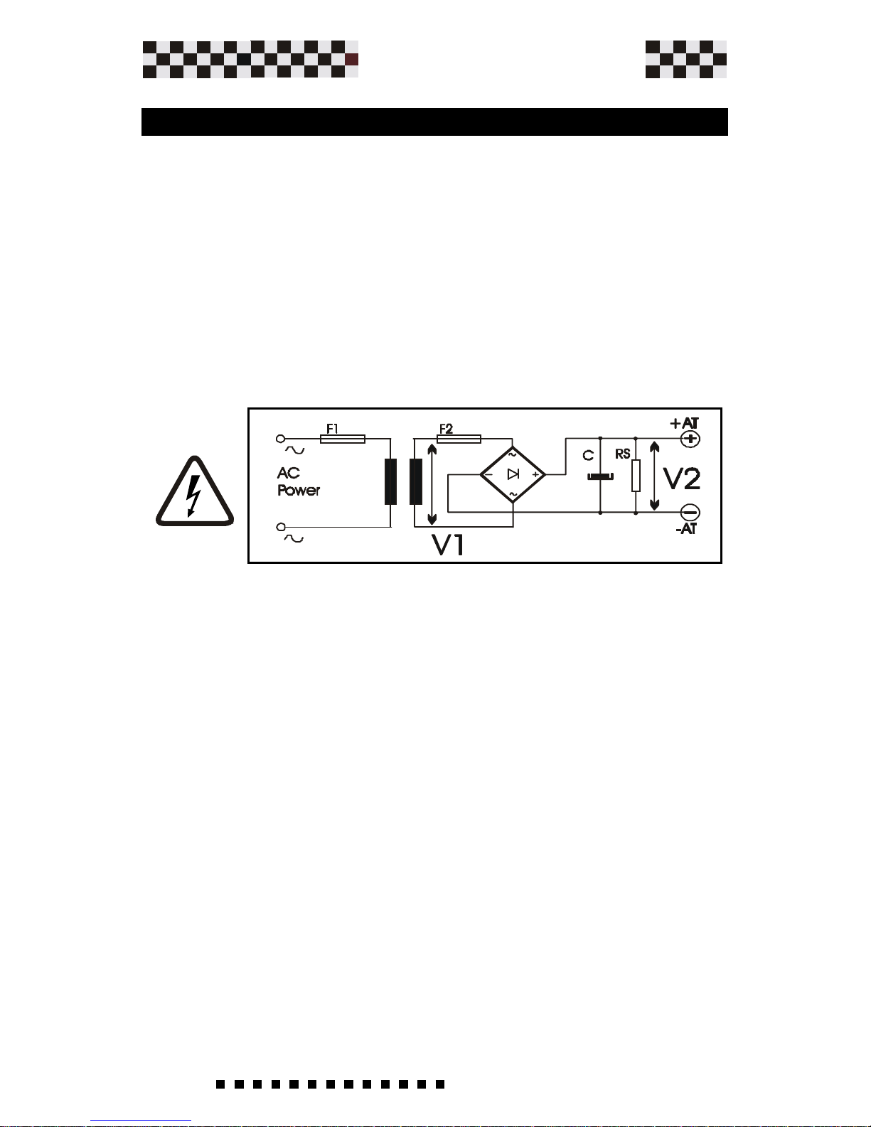
3.2 Power Supply Construction and Rating
Installation
W ARNING:Use only Un-regulated power supplies with the
Microspeed Plus Drive.The power supply is used to
absorb the motor's BEMF. Als, with this scheme, no
braking resistor are needed.
The MicrospeedPlus was designed to generate all required
supply voltages in the Drive, so only a simple single voltage power
supply is needed. Use the schematic and formulas provided
below to design a supply that will be trouble-free and handle the
power needed by the drive.
Transformer:
A single ground is used in the drive that is
connected to -AT, so DO NOT USE AN AUTO
TRANSFORMER. Use a standard heavy duty power transformer
without center taps on the secondary as shown in the schematic
above. The VA rating should be 10% greater than the power
needed by the system to insure cool operation. DO NOT
CONNECT ANY TRANSFORMER PRIMARY, OR
SECONDARY SIGNALS T O GROUND.
Keep the +AT and -AT wires, between the power supply and the
Microspeed Plus, as short as possible.
Page 25
25
Service Manual
Plus
MICROSPEED
Installation
Where:
VM= E+(R x Im)............ motor voltage
E = Ke *n°/1000............ FCEM motor (Vdc)
Im = I motor (A)
Ri = Winding resistance (Ohm)
Ke =Voltage constant (V/kRPM)
n° = MAX speed (RPM)
V1(Dc) = VMotor
0,9x1.36
Voltage
:The primary voltage depends on what is available
locally for a single phase. The secondary voltage is
calculated from the motors voltage at the required operating
speed.
The secondary voltage V1 is:
Page 26

26
Service Manual
Plus
MICROSPEED
The transformer's nominal power is calculated based upon
the sum of power from the single motors driven.
Or Better:
Note: In multi-axis applications, the transformer's power can
be downgraded by 30%.
••
••
• POWER: If the power of a transformer exceeds a
determined value, the inserted straightening point
could be damaged in the enabling phase, due to
overcurrent from the capacitors.
•max. power per trasformer is 7KVA;
Where:
Pn Motor = nominal power each motor.
n = max. speed of motor in RPM.
Cn = nominal torque of motor in (Nm).
Pn Motor = n x Cn
9,55
C (uF) = P (VA) transformer x 1000
V2
Power Transformer:
Capacitor filter:
In regards to the capacitor filter we suggest a working voltage
of:
--100 Vdc for Microspeed plus 60
--200 Vdc for Microspeed plus 140
--300 Vdc for Microspeed plus 200
It's capacitor value is derived using the following formula:
P(VA)=Power absorbed motor 1+Power
absorbed motor2+etc......
Installation
Page 27

27
Service Manual
Plus
MICROSPEED
RS (Ohm) = 20.000.000
C (uF)
P (W) = V2
2
RS
Installation
Where V2 = DC voltage present on capacitor without load. Such
a capacitor is used to filter the straightened voltage from the
power supply and to recover energy during the motor's braking
phase.
Where: RS is the resistor value in Ohm
P is the power of said resistor in Watt
Discharge resistor
The bleeder resistor is used to drain the charge from the filter
capacitor when power is removed from the supply. This helps
in bringing the supply voltage down quickly. This resistor is
mounted directly across the filter capacitor. To calculate the
correct value and wattage use the formula below.
Page 28

28
Service Manual
Plus
MICROSPEED
F 1 = (VA) trasformer x 1,1
Vac (primary) ac
F2 X MCS 2,5/5 =3,16A
X MCS 5/10 =5A
X MCS 8/16 =10A
X MCS 10/20 =16A
X MCS 14/28 =20A
X MCS 20/40 =25A
Installation
Fuses are required on both the primary and secondary of the
transformer to protect against harm to the system and the
transformer itself. They need to be of the slow blow type to
handle current in-rush at power-up. Locate the primary fuse
(F1) on the hot leg of the AC input power and the secondary
fuse (F2) on the + side of the secondary output, before the
rectifier. Use the formula below to calculate the correct values
for both fuses.
Where:
Fuses
A separate fuse F2 is required for each drive in a multi-axis
system.
Page 29

29
Service Manual
Plus
MICROSPEED
3.3 Multiple Connections
Installation
Incorrect
Wiring
Technique
Use This
In case of connecting more than one axle to a single supply,
always connect each drive DIRECTL Y to the supply and keep
the wires as short as possible, twist the + and - leads together
as twisted pairs. (try not to exceed 1,5 feet (1m) in length.
Page 30

30
Service Manual
Plus
MICROSPEED
3.4 Ground and Shield Connections
Installation
Page 31

31
Service Manual
Plus
MICROSPEED
Description:
It is important that the drive's ground connections are as short as
possible and no longer than 8 inches (20 cm). The figure shows
the connection using terminals fixed to the drive's base (bottom).
This connection also reduces disturbances in the net.
The Motor ground cable has to be external (not inserted in a
multipolar cable) with minimun section 1.5 mmq (0,059 square
inch).
Drive power and signal cables must be shielded. The cable
shields must be connected to the body of the motor.
Shelded cable is not required for the motor power cable, the +M
and -M cables should be twisted together.
On the follwoing page you'll find additional installation instructions
in respect to EMC requirements.
Installation
Page 32

32
Service Manual
Plus
MICROSPEED
3.5 Instructions for EMC Requirements
Installation
The regulated standard in accordance with conformity of
electromagnetic is summarized in Regulation CEI EN 61800 (complete).
Microspeed Plus conformity is assured only if it is installed
following the precise assembly criteria expressed below. The
fundamental assembly characteristics are summarized bolow:
--1) Use of appropriate network to filter the line (transformer input),
from disturbances conducted or produced by the drive.
A series of filters released by AXOR are available for this purpose.
--2) Use of shielded cables, both for power connection (to the
transformer and the motor), and for signal connection (also to the
controller).
--3)Using the division of cables technique. Separate power cables
from signal cables.
--4) The correct ground connection of predisposed parts.
Of all of the mentioned system, the use of network filters is without
a doubt fundamental in soppressing disturbances.
Axor, after tests, has recognized some good solutions, about its
products.
Concerning equipment where are mounted other sources, Axor
cant evaluate the global equipment. In the following page, are
reported some foundamental configurations, with the suggested
filters.
We did an agreement with Schaffner and Timonta products. The
market offers other product with the same characteristics, but not
yet checked from Axor.
When other products will be checked and approved, it will be
notified.
Follow reported an example about the noise level with and without
filter as explained in the following pages.
Network Filters
Page 33
33
Service Manual
Plus
MICROSPEED
Continued
Installation
The recommended filters for the product lines in some of the main
configurations are shown in the table on page 34-35. These filters
are produced by SCHAFFNER and TIMONTA.
Other products with the same characteristics may be sufficient,
but have not been tested or evaluated by AXOR.
In choosing the filter, we also considered the current absorption
of its connecting devices. AXOR recommends connecting the filter
before the power supply transformer. This method, besides
offering better disturbance soppression result, also allows for the
use of filters capable of supporting a lot less current, consequetly
they're cheaper (takes advantage of the transformer's ratio).
Follow the formula below for the filter dimensions to be used with
the Microspeed Plus.
I(A) = P tot
1.73 x V primary
Where:
I=is the nominal current in Amperes for the necessary filter.
Vprimary= is the voltage of Transformer.
Ptot=is the motor's max. power absorption in watts(VA)
Ptot=VA=Motor power1+motor power 2+...ect.
Instructions for EMC requirements (continued)
Page 34
34
Service Manual
Plus
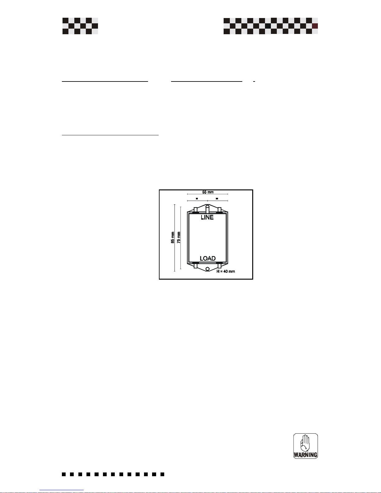
MICROSPEED
For filter connection (divert to building ground the unwanted frequency)
considering such devices can produce small leakage current towards
building ground (this current amounts to "some" of milliamperes). For
these precautionary reasons, it is necessary to connect the filter to
building ground prior to connecting the power supply.
Regarding current leakage, remember that it must be considered when
sizing differential devices, thus avoiding undesired interventions. The
precise data relative to our filters can be found below.
Installation
Mechanical and Electrical Characteristics
Below is a table showing the electrical characteristics of our
recommended filters. Pay particular attention to leakage, differential
adjustements, and nominal current in accordance with operational temperature.
Instructions for EMC requirements (continued)
Below is a table showing the electrical characteristics of our
recommended filters. Pay particular attention to leakage, differential
adjustements, and nominal current in accordance with operational temperature.
Type Current Leakage Curr. Power loss Weight
(A) (mA) W Lb.
SCHAFFNER FN355 3(40°C) 0.07 (400V 50Hz) 1.5 0.55
SCHAFFNER FN2070 3(40°C) 0.4 (250V 50/60Hz) 0.55
TIMONTA FMW4 4(40°C) <0.5 (400V 50/60Hz) 1 0.6
TIMONTA FSS2 3(40°C) <0.5 (250V 50/60Hz) 0.6
TIMONTA FSS2 6(40°C) <3 (250V 50/60Hz) 0.6
The TIMONTA FMW65-4: 3 PHASE Series filters are furnished with Faston connectors for both input and output.
Max. voltage : 440Vac
Max. current : 4A @ 40°C
The SCHAFFNER FN355-3: 3 PHASE Series filters are furnished with Faston connectors for both input and output.
Max. voltage : 420Vac
Max. current : 3A @ 40°C
Working temperature: -25° +85°C
Page 35
35
Service Manual
Plus
MICROSPEED
Installation
NOTE:
--The filter must be placed before the trasformer.
--All connections of the Net filters must be shielded and shouldn't be
longer that the length shown in the scheme.
--The cable shield must cover the entire length of the wire and be as
close as possible to the connection terminals.
--Always use shieded cable (twisted) to connect the motor and the
drive.
--Avoid passing signal and power cables through the same channels.
--It is very important that the panel where the filters are mounted is
connected to ground.
--Power and Command/Signal condotors should not be placed in the
same channels (keep separate). Avoid twisting, crossing, etc. If
crossing is inevitable, try to cross at a 90 degree angle. Where
possible use metallic channels connected to ground.
Instructions for EMC requirements (continued)
Mechanical dimension
The TIMONTA FSS2-65-3 TIMONTA FSS2-65-6 : Single
PHASE Series filters are furnished with Fast-on connectors for both input and
output.
Max. voltage : 250Vac
Max. current : 3A @ 40°C, Max. current : 6A @ 40°C
The SCHAFFNER FN2070-3: Single PHASE Series filters are furnished with
Fast-on connectors for both input and output.
Max. voltage : 250Vac
Max. current : 3A @ 40°C
Working temperature: -25° +85°C
Page 36
36
Service Manual
Plus
MICROSPEED
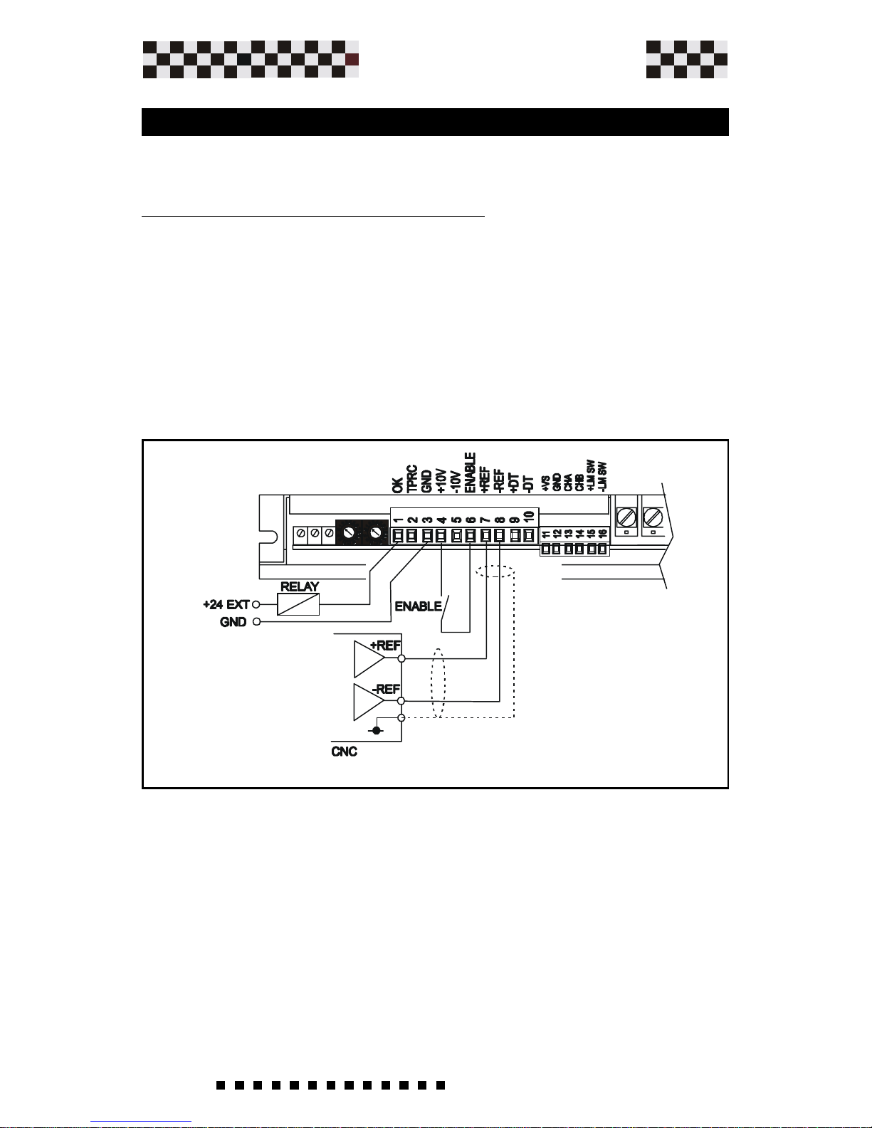
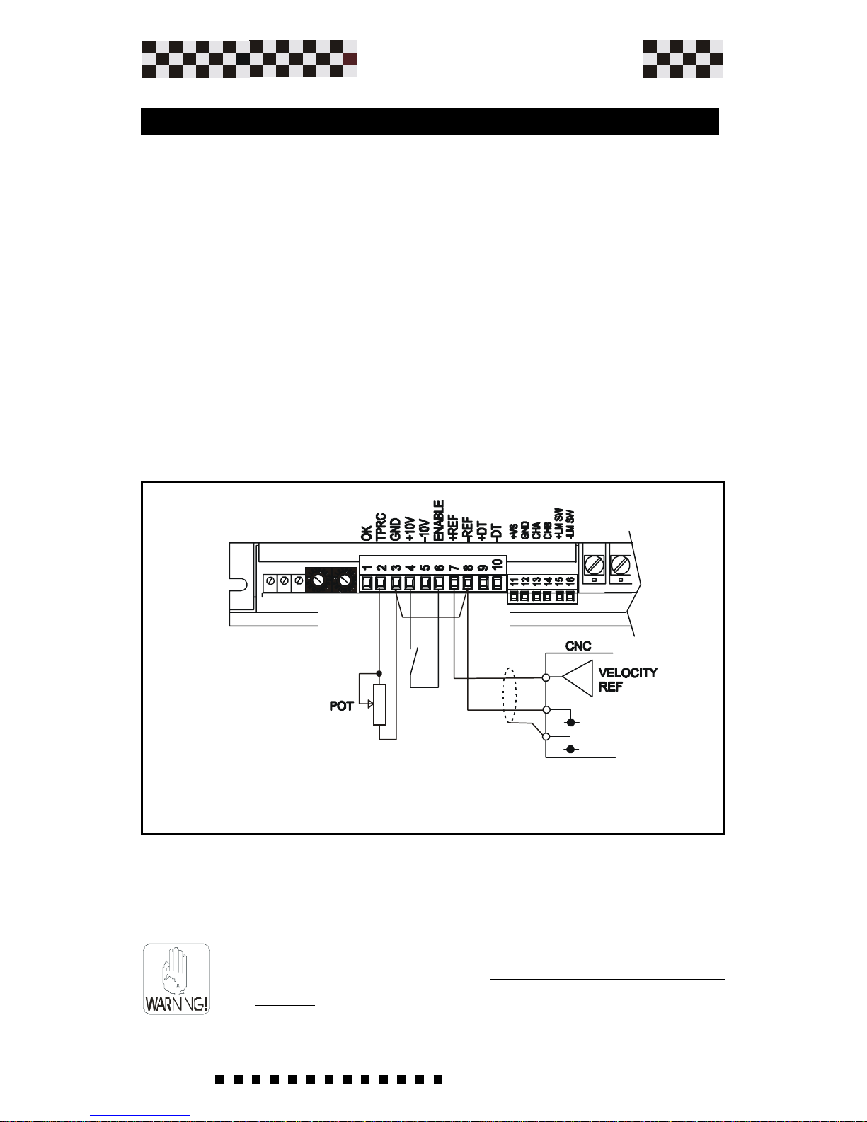
The following diagram shows an application utilizing a
differential reference from a C.N.C.
The drive is enabled using the Auxiliary power supply +10V
(Connector 4). It is possible to use an external power supply
for this function (24Vdc). Remember to also connect the GND
of the power supply to Connector 3.
3.6 Examples of Microspeed Plus Connections
On connector 1 "OK" an external relay coil was connected.
This output has a rating of 50mA Max.
Do Not connect a supply exceeding 24Vdc. Connect the
Power Supply GND externally using connector 3
.
Installation
Page 37
37
Service Manual
Plus
MICROSPEED
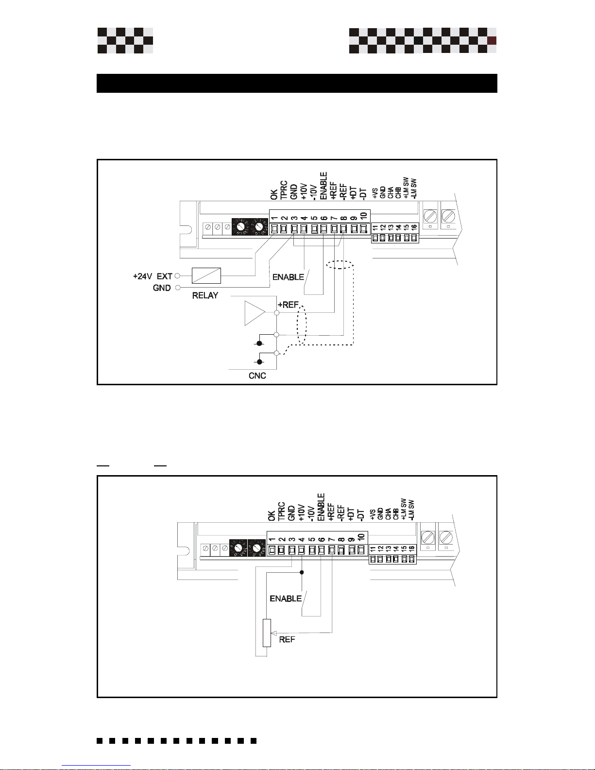
Installation
The following figure shows an application with speed reference
connections using an internal MICROSPEED PLUS power supply.
The speed potentiometer must have an included value between
>10 and <47Kohm.
The following diagram shows an application using speed
reference connections in the Common Mode.
3.7 Common Mode Reference
Page 38
38
Service Manual
Plus
MICROSPEED
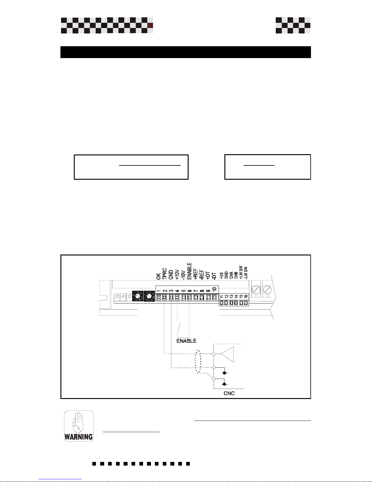
With a voltage output (ex. from a CNC) you can command the
drive in torque mode. Applying a signal of +/- 10V at TPRC, the
MICROSPEED PLUS to supply positive or negative peak current.
For this configuration soldering point S8 is closed , S9 and S12
is open.
The formula to determine the value of Ving to apply in TPRC in
order to obtain requested current is the following:
Other examples:
Mcs Plus10/20A.......+5V gives current of -10A.
...... - 5V gives current of +10A.
Mcs Plus14/28A.....+3.2V gives current of -9A.
..... - 3.2V gives current of +9A.
3.8 Current Reference (Torque Mode)
Ex: 10 x 9 = 3,2V
28
Ving =10 x I request
I pk MCS
In this case the loop of internal velocity automatically
excludes itself .
Installation
Page 39
39
Service Manual
Plus
MICROSPEED
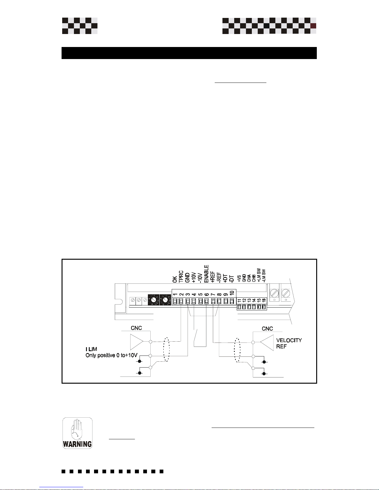
3.9 Current Output Limitation
With a voltage output (ex. from a CNC) only positive between 0V
and +10Vdc, you have a limitation of output current (from zero to
max. size) drive's.
For this configuration the soldering point S8 is open, S9 closed.
The speed ring remains active and uses the input reference
signal.
Example:
Mcs Plus 10/20A.......+5V limits the current to +/-10A.
Mcs Plus 14/28A.....+3.2V limits the current to +/-9A.
The current polarity functions as speed ring output.
In this case the loop of internal velocity remains
active.
Installation
Page 40
40
Service Manual
Plus
MICROSPEED
Installation
By connecting a resistance load at TPRC (ex. a potentiometer),
you'll obtain the limitation current output.
For this configuration soldering point S8 is closed , S9 is open.
Connect a resistence of 1/4W - 1/8W between the TPRC
terminal and the GND terminal, or a potentiometer connected
as in figure 5.
With external Resistance of 47K you limit the current at 50% of
I Max. of size.
Example:
Mcs Plus 10/20A.......47Kohm limits the current to +/-10A
The potentiometer of the output
current limitation 470K-1M Ohm.
In this case the loop of internal velocity remains
active.
3.9a Current Output Limitation
(continued)
Page 41
41
Service Manual
Plus
MICROSPEED
10
10
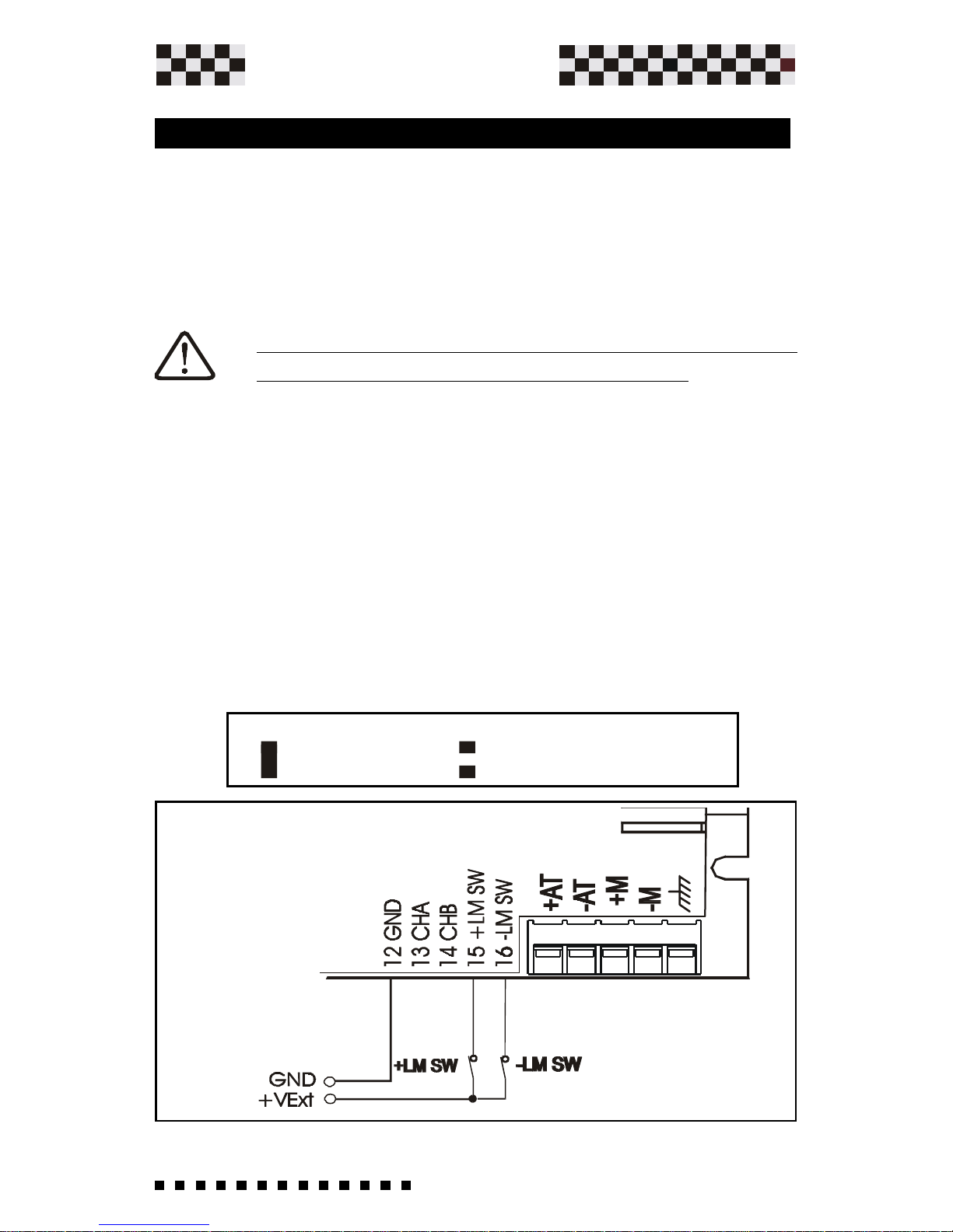
Installation
It's possible to enable clockwise (CW) and counter-clockwise
(CCW) motor rotation by connecting the +LM SW and -LM
SW inputs.
They may be used to block motor rotation when the machines
overflow contact is intercepted.
Note - When one of these said contacts is intercepted
the motor stops with the required inertia.
The Enable input in regards to this input always has priority.
To enable such a function, you must:
-- Open soldering point S10
-- Open soldering point S12 ( disable a internal allarm for
missing tachogenerator or encoder).
-- Then connect on said input a positive voltage (between
+5Vdc and + 24Vdc) coming from -for example two N.C.
contacts. You may connect an external supply "combining
negative" as well as from one of the supplies furnished on the
Microspeed Plus. Function: At opening one of the following
contacts you enable the motor rotation in the corresponding
direction.
3.10 Limit Switch Input +/-
=NOT ENABLE =+/- LIMIT SW. ENABLE
Page 42

42
Service Manual
Plus
MICROSPEED
Power cable specification is recommended as follows:
1.5 square mm up to 6/12
2.5 square mm up to 10/20
The +M and -M drive outputs can be connected directly to the
motor terminals.
The minimum motor inductance value is 0.5 mH. In the case of
motors driven with armature inductance lower than 0.5 mH, it is
necessary to use a chokes connected in series with the motor.
3.11 Power Connections
Installation
Page 43

43
Service Manual
Plus
MICROSPEED
4.1 Starting Procedures
Two ways to place the Microspeed Plus into function:
• If the drive has already been pre-adjusted for its motor and
has accompanying connection sheet, proceed with chapter on
"Starting procedures".
• If the drive hasn't been pre-adjusted for its motor, first consult
the chapter on "Personalization and Settings" and Chapter 5.0
4.0 Preliminary Checks
The standard drive is furnished with the following
characteristics:
• Nominal and Peak current of drive corresponds to the drive
size; "RIN and RIP resitors are not mounted".
Ex.: Microspeed Plus 140 10/20A ; 20A peak for 2 seconds, 10A
upon return.
• Encoder speed adjustment for 3000 rpm at 10V ref. with
encoder of 1000 Imp/rev. "RDT resistor = 22Kohm".
• KV and DER positions are "1".
How to proceed
What to check
Verify that all signal and power connection terminals are
accurately closed/tightened and execute a visual check of the
drive's cabling.
Start up procedures
• Remove load from motor shaft and be prepared to quickly
shut off power supply if required. (Warning: keep motor well
fixed to the ground/floor or attached to a mechanical support).
• Insert the fuses in series with alternating power or insert
the corresponding thermal magnet, insuring the available
power value by measuring with a tester.
Page 44

44
Service Manual
Plus
MICROSPEED
• Powering up the drive.
Under normal conditions the green L.E.D. comes on after
approx. 1 second.
Prepare to power up the drive by first insuring that the
reference signal is zero =0V.
ATTENTION: If possible, in the case of piloting motor with a
C.N.C. controller, make sure the manual reference with the
calculated error corrections of the same are not inserted.
(Space ring not inserted).
• Power up the Enable input. (It's a good application norm
to always supply the Enable command after the powering up
the drive).
• Furnish the reference signal.
Increase the speed reference signal up to minimum value
(approx. 1V) and observe the motors sense of rotation. If the
motor rotates contrary to what you require, shutdown and invert
the +REF and -REF,
• Reconnect the motor's shaft to the load and insert the
space ring of eventual controller. If at this point you still have
the same results as those verified before insertion and the
controller doesn't show errors, the system is regulated
correctly.
• Now execute standard working cycles verifying that no
protections intervene.
Start up procedures
Page 45

45
Service Manual
Plus
MICROSPEED
Adjustments
5.0 Personalizazion and Settings
Soldering points
Personalization base
adjustments
If the drive isnt adjusted with the proper servomotor, follow these
procedures. If changes need to made to the internal drive setting
powering, please wait at least 10 seconds after the power has
been removed and the OK LED is off.
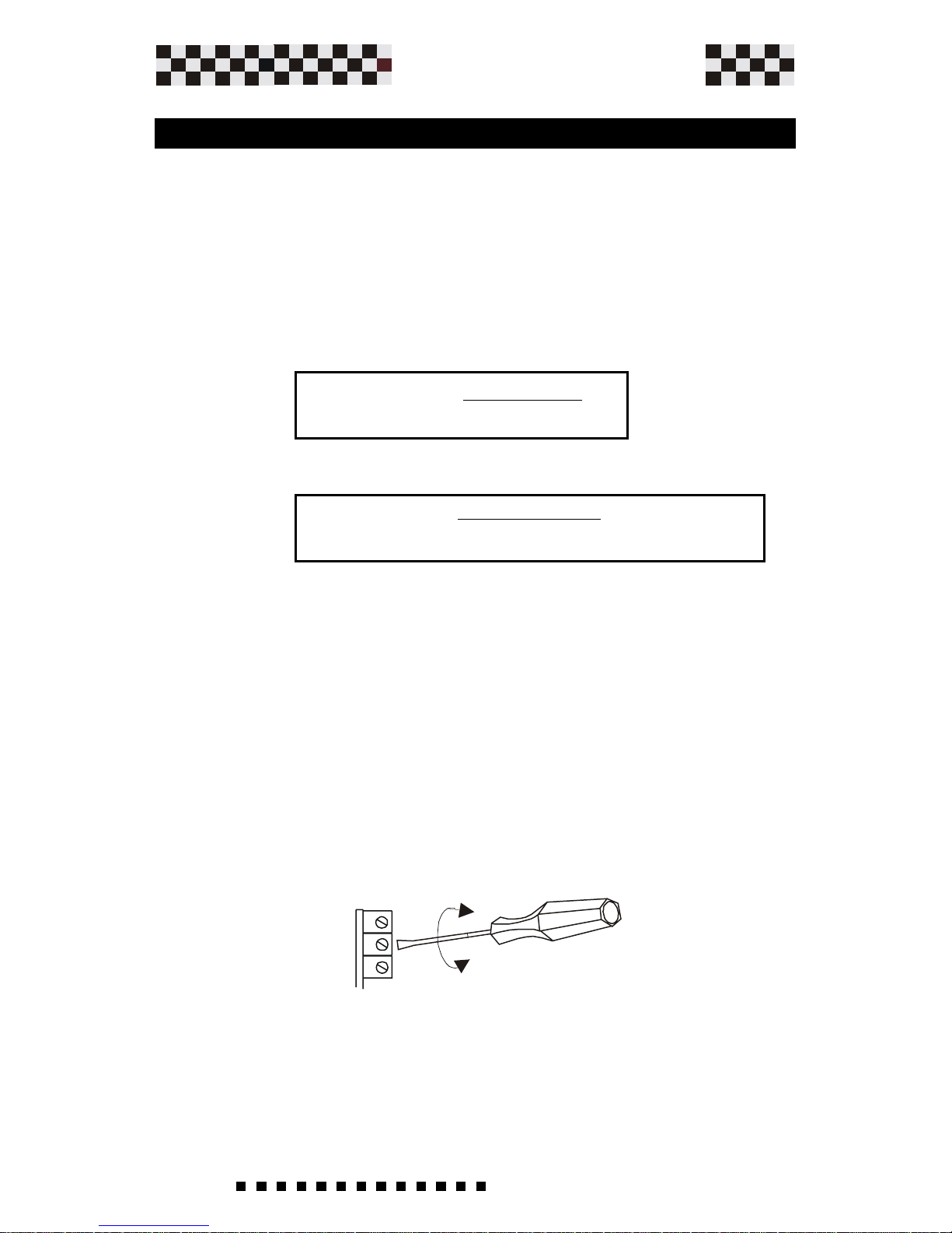
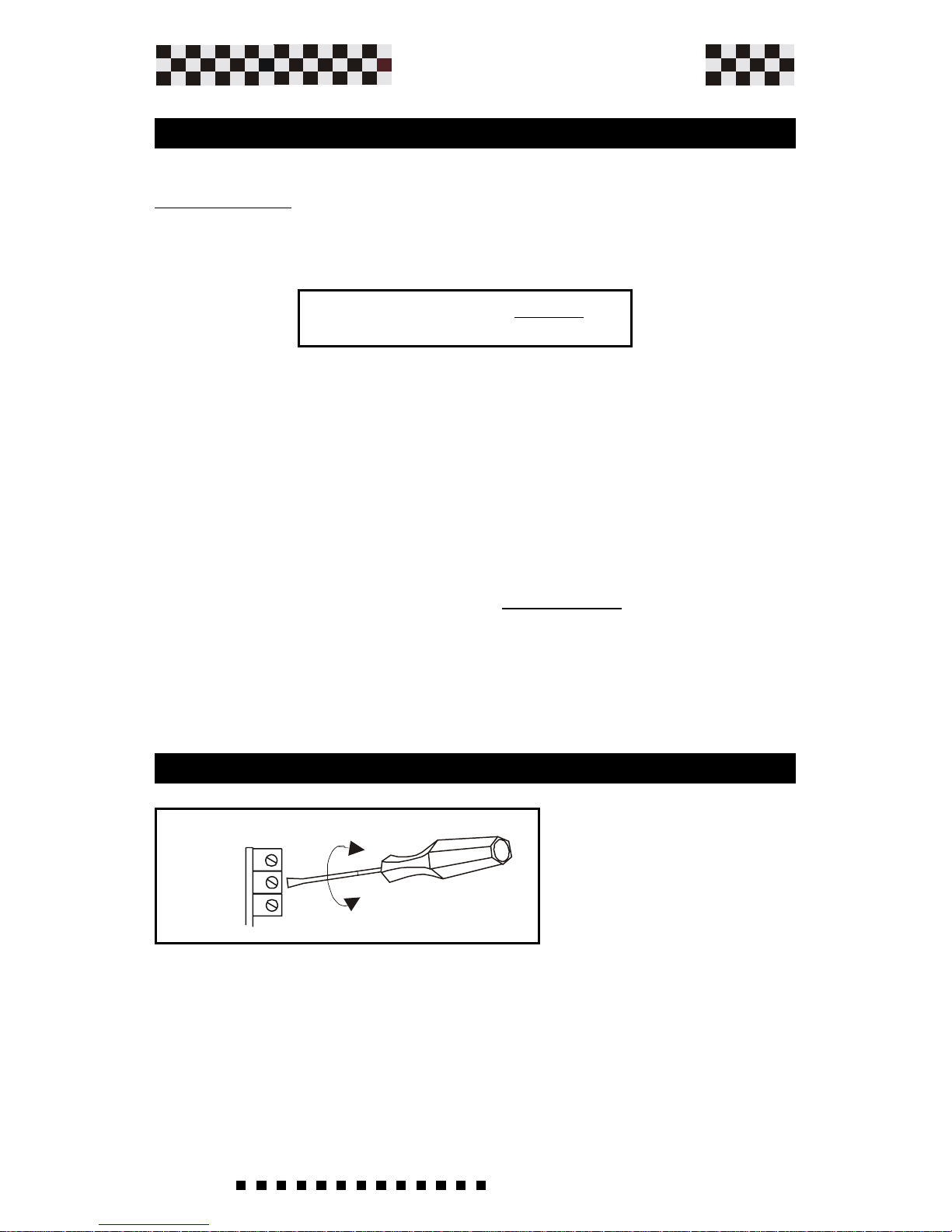
All of the personalizations are located inside of the MICROSPEED
PLUS. To gain access to the adjustment pads and the solder
bridges, unscrew (A) , and remove the cover (B). (See figure
above).
A
A
B
Page 46

46
Service Manual
Plus
MICROSPEED
RENC
GAIN
RIP
RKV
RCA
RDT
RIN
RA
RAMP
5.1 Adjustement components
Droop compensation for internal motor resistance
(RI);Chapter 5.4 .
Nominal drive current resistor; Chapter 5.6
Armature Feedback resistor. It permit adaptament
at the costant motor tension. (See chapter 5.4)
Peak drive current resistor ; Chapter 5.6
Changes static gain in the velocity loop. Open
Solder bridge S6 and insert R GAIN if a change is
required. Consult factory for the correct value.
Resistor value that form the proportional/integral
network of the velocity Loop gain.
Standard values are 100 Kohm, there are disabled
by opening Solder bridge S5.
Adjustments
If we insert this resistance, we adapt KE
tachogenerator costant with input amplifier costant.
If the KE costant is small, we can bridge this
resistance (See chapter 5.3)
It gives ACC/DEC time. (See chapter 5.7)
If we insert this resistance, we adapt Impuls
Encoder costant with input amplifier costant. (Optional See chapter 7.1)
Page 47

47
Service Manual
Plus
MICROSPEED
CKV
CDER
Derivative constant capacitor, increases the velocity
loop derivative constant.
Capacitor value that form the proportional/integral
network of the velocity Loop gain.
Standard values is 47nF, there are disabled by
opening Solder bridge S5.
Adjustments
Adjustement components
(Continued)
Page 48
48
Service Manual
Plus
MICROSPEED
S1 Normally open.If Closed, when the IN protection is lit the green
OK LED goes off and is unable to allow the Drive OK LED to come
on.
S2- S4 Normally open. (See Chapter 5.7 Ramp time adjustment).
S3 Normally closed. (See Chapter 5.7 Ramp time adjustment).
S5 Normally closed. If Open , install components for the Dynamic
velocity costant CKV and RKV. (Standard constant RKV=100Kohm
, CKV= 47nF).Consult factory for proper use.
S6 Normally closed. If Open - you must insert theNew GAIN
resistor. (Static Gain). Standard value= 22ohm
S7 Normally open.If closed enables Armature Feedback. See
chapter 5.4
5.2 Solder Bridges
Adjustments
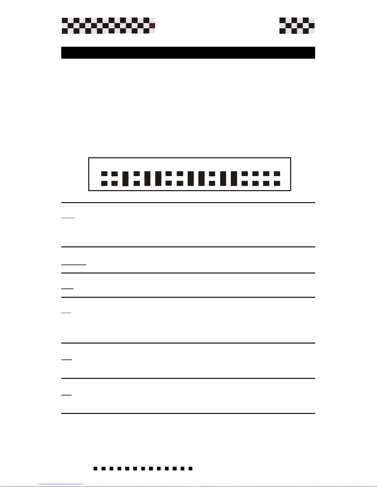
17 Solder Bridges located on the left hand side of the drive are
used to change internal and external functions on the Microspeed
Plus. Below are the descriptions of each solder bridge functions.
Verify the corresponding solder bridge closings required by the
drive.
This Drive is factory set with the following solder bridge
configuration.
1234567891011121314151617
Page 49

49
Service Manual
Plus
MICROSPEED
S8 Normally open. (See chapter 3.8, 3.9, 3.9a)
S9 Normally closed. (See chapter 3.8, 3.9, 3.9a)
S10 Normally closed. (If open predisposes input function
+/-LM SW). Chapter 3.10
S1 1 Normally open.If closed enables Encoder Feedback. See
chapter 7.1
S12 Normally closed. If open you disable a internal allarm for
missing tachogenerator or Encoder.
S13 Normally closed. (Power supply on terminal +Vs=5Vdc.
If open configure +V=+12Vdc).
Only for Optional Encoder.
S14 -S15 Normally open.If closed you insert for each encoder
input a pull-up resistor of 3.3 Kohm to internal +14V.
Only for Optional Encoder.
S16- S17 Normally open.If closed you insert for PWM and
DIR input a pull-up resistor of 3.3 Kohm to internal +14V.
Note: Closed only for Pwm+Dir Optional.
Adjustments
NOTE: Further along in the manual all desired speed feedback are
highlighted the soldering points to close.
Page 50
50
Service Manual
Plus
MICROSPEED
RDT
(Kohm)
= Kdt x n x 9,7 _
8
1000 x Vref
RDT
(Kohm)
= 10 x 3000 x 9,7 _
8=21.8 Kohm
1000 x 10
The drives are provided with the RDT resistance mounted on
board.The drive is adjusted for 3000 rpm with a tachometer costant
10v/1000 rpm referred to 10V reference.
If you desire to change this resistor, just open the cover of the
drive, then change the value of the resistor.
To calculate it,please use the following equation:
Example: KDT=10, n=3000, Vref=10
Where:
Rdt is the value expressed in Kohm with a power rating of 1/8 or
1/4w.
Kdt is the tachogenerator costant
n° is the max speed express ed in RPM.
Vref is the max voltage reference expressed in Volts.
When the RDT resistor is mounted adjust the fine speed by using
the VEL potentiometer located in front of the drive.
Clockwise...............Increases the speed.
CounterClockwise..Decreases the speed.
The range adjustments are +/- 20 %.
5.3 Speed adjustment with tacho feedback
Adjustments
VEL
BIL
ACC
Page 51
51
Service Manual
Plus
MICROSPEED
RA
(k ohm)
= 166 x Vref
E - 1,4 Vref
RA
(k ohm)
= 159 x Vref
E - 3,3 Vref
RA
(k ohm)
= 158 x Vref
E - 5 Vref
Adjustments
5.4 Speed adjustment with Armature feedback
Armature feedback mode may be used as speed feedback
when a tachogenerator is not fitted to the motor.
Speed control is then less precise(the regulation range is 1/
20, and below this value the torque is reduced).
This funciton will be enabled by solder bridge S7 Closed, S12
open, and mounting in the socket RA and RCA resistors.
RA resistor It will be mounted on the personalization zone to
adapt the system to the voltage motor costant.
To calculate it use this equation:
RA
(kohm)
= 166 x 10
= 36 Kohm
60 - 1,4 x10
E = 3000 x 20
=
60
1000
WHERE:
E
=
n x Ke
1000
Ke= Servomotor BEMF at 1000 rpm
Vref= Max voltage reference.
n= max speed express in rpm.
Use the nearest commercial value, 33 Kohm.
Example:Servomotor with Ke=20 n=3000 RPM Vref=10 For MCS
Plus 60.
MCS PLUS 60
MCS PLUS 140
MCS PLUS 200
CONTINUE
Page 52
52
Service Manual
Plus
MICROSPEED
RCA
(k ohm)
= 0,5 x n Ke
Vref Ipk Ri
RCA resistor It will be mounted on the socket , to compensate for the voltage drop due to the motors internal resistance.
To calculate it,use this equation:
Use a resistor of 200 Kohm or the higher value.
RCA
(kohm)
= 0,5 x 4000 x 50
=200 Kohm
10 x 20 x 2.5
Example: Drive 10/20 A , Ri=2.5 ohm
If,after this procedure the motor is unstable increase the value by
using the next (higher) commercial value avalaible.
WHERE:
n= max. speed expressed in rpm.
Ri=Total motor resistance with brushes.
Ipk =Peak current, (size)of the drive.
Ke=Sevomotor BEMF at 1000 rpm.
Vref= Max voltage reference.
Adjustments
5.4 Speed adjustment with Armature feedback
5.5 Adjusting Speed Balance (Offset)
The Microspeed Plus is provided with a BIL potentiometer
that allows the motor to be adjusted to zero speed when 0.0
Vdc is applied to the +REF. Re-adjust the Bil trimmer to correct
eventual system offset. (You may compensate +/- 200mV from
reference input). With the reference input at Zero turn the BIL
potentiometer until the motor stops moving.
VEL
BIL
ACC
Page 53

53
Service Manual
Plus
MICROSPEED
Adjustments
5.6 Nominal and Peak Current Adjustment
Peak Current
Note * = No resistor mounted.
Nominal Current
Note * = No resistor mounted.
The Microspeed Plus is pre-set to the nominal current rating
of the drive, if a lower current is needed to match the motor
used, refer to the chart below and select the correct resistor
value to be fitted as RIN. Use the table below to select the
correct value.
To reduce the value of the peak motor current , its necessary
to mount RIP on the header located inside of the drive.Use
the table below to select the correct value.
eulaVNIR
mhoKni
* 33 22 51 01 8,6 7,4 3,3 2,2 5,1 1
2/1SCM
1 69,0 29,0 68,0 87,0 17,0 36,0 55,0 64,0 93,0 23,0
5/5,2SCM
5,1 4,2 3,2 1,2 9,1 7,1 5,1 3,1 2,1 1 8,0
21/6SCM
6 8,5 5,5 2,5 7,4 3,4 8,3 3,3 7,2 3,2 2
02/01SCM
01 6,9 2,9 6,8 8,7 1,7 3,6 5,5 6,4 9,3 2,3
82/41SCM
41 7,31 31 2,21 2,11 01 9,8 7,7 5,6 4,5 5,4
04/02SCM
02 2,91 4,81 2,71 6,51 2,41 6,21 11 2,9 8,7 4,6
eulaVPIR
mhoKni
* 86 74 33 22 51 21 01 2,8 8,6 6,5
2/1SCM
2 9,1 8,1 7,1 6,1 5,1 4,1 3,1 2,1 1,1 1
5/5,2SCM
5 8,4 6,4 4,4 4 7,3 4,3 2,3 3 7,2 5,2
21/6SCM
21 5,11 1,11 6,01 8,9 9,8 3,8 7,7 2,7 6,6 6
02/01SCM
02 3,91 6,81 7,71 3,61 8,41 8,31 9,21 21 11 01
82/41SCM
82 72 62 52 32 7,02 3,91 81 7,61 4,51 41
04/02SCM
04 6,83 2,73 4,53 6,23 6,92 6,72 8,52 3,42 22 02
Page 54
54
Service Manual
Plus
MICROSPEED
S3 S2 S4
Closed Open Open
Closed Closed Closed
Open Closed Closed
FUNCTION
Ramp Disabled
Ramp Enabled
Ramp Enabled
RANGE
0 Sec.
0,1 - 1sec
by RAMP
NOTE
Standard
adj by ACC
adj by ACC
1
Res. RAMP 680K 820K 1MOHM
TIME 0,2-2,6 Sec. 0,3-3,2 Sec. 0,4-3,9Sec
2
This function is enabled by solder bridges S2, S4 (closed).
It allows adjustment of the ramp slope during both acceleration and
deceleration.
Adjusting the ACC potentiomenter, located in front of the drive,
clockwise (cw) increases the ramp time between 0,1 and 1S (It for
a 10V reference). (See figure below)
5.7 Ramp time Adjustment
Adjustments
It is also possible to modify the range of the ramp by opening
solder bridge S3 and mounting a resistor (RAMP) with the values
shown in the table 2) below.
Page 55

55
Service Manual
Plus
MICROSPEED
Adjustments
Usually, these settings are made by the factory and
do not need to be changed.
Only re-tuning by KV and DER potentiometer is
required.
If high inertia loads are present (ratio 3:1 between load and
motor), it is necessary to set the proportional gain KV
potentiometer and the derivative gain DER potentiometer.
The adjustment procedure must take place with the load
connected to the motor.
Connect a square wave (0,5 hz, +/-1V) function generator to
the input speed reference terminals.
Connect the "channel A" probe of the memory oscilloscope
to the test point TEST1. (The ground of the probe must be
connected to the GND of the drive).
Adjust the DER and KV potentiometers.
Be sure that the loads motion doesnt create a safety risk.
Apply power to the drive and start it.
The load will begin to move alternatively; if possible increase
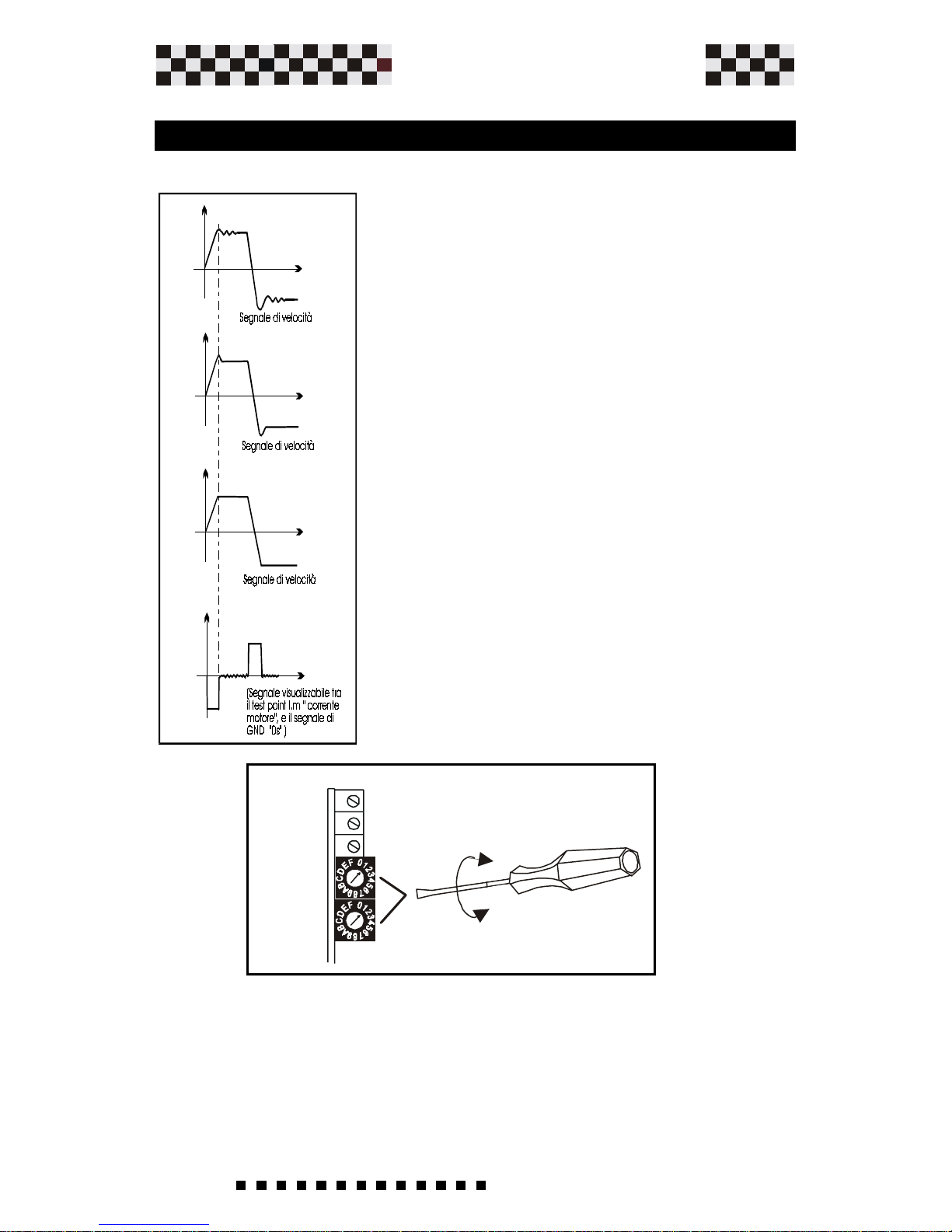
the generator amplitude to +/-2V.
Check the signals in the oscilloscope; the waveforms should
be as shown on the next page.
5.8 Dynamic Constant Adjustments
dinamiche
Page 56
56
Service Manual
Plus
MICROSPEED
Increase the gain by turning clockwise
(cw) using "KV potentiometer" until
achieving a situation as shown on the left.
Insufficient proportional gain.
To reduce the overshoot adjust
clockwise (cw) using "Der
potentiometer" until achieving a situation
as shown on the left.
Caution: Do not set KV too high : it can
cause unnecessary motor heating
caused from ocsillating currents in the
motor.
It's possible to increase the velocity loop derivative constant
by inserting a capacitor CDER on the personalization
adjustment.
Adjustments
5.8 Dynamic Constant Adjustments
(Continue)
VEL
BIL
ACC
KV
DER
Page 57

57
Service Manual
Plus
MICROSPEED
6.0 Troubleshooting
Troubleshooting
1) When power is on -the green OK LED doesn't come on.
-Check the voltage between +AT and -AT with a multimeter
2) With the green OK LED on the motor doesn't run when
the drive is enabled.
- Check input signal (Enable-reference)
3) When the drive is enabled the green OK LED goes off and
the red O.C. LED comes on.
- Short circuit between motor terminals or motor winding is
connected to ground. Switch off and measure with tester.
4) During motor deceleration phase the green OK LED
blinks.
-You've exceeded max. consented voltage. Verify filter capacity
value. (See Power Supply chapter).
5) During operation the motor stops and the S.T. LED
comes on.
-Drive operating temp. is too high (more than 40°C). Ventilation
missing (where required).
6) At Startup or Enabling the DT Led comes on.
-Missing Tachogenerator Signals or reversal.
-Missing Encoder Signal or reversal.
Page 58

58
Service Manual
Plus
MICROSPEED
7.1 Encoder Feedback
(option)
Options
The encoder feedback is an option of the MICROSPEED PLUS
drive.
This allows you to adjust the motor speed,using a signal coming
from an encoder with two channels.
This solution saves the use of a tachogenerator,using the same signal
requested for the position control.
The performance of the drive at low speeds are improved with the
high encoder resolution. It is reccomended that you use an encoder
with resolution of at least 500 imp/rev. An auxiliary power supply
+5 V or + 12 V is avalaible to supply the encoder.
Dont exceed the load declared.
If the encoders absorption is unknown,please check it by a
milliamperometer connected in series to +Vs.
If the value is higher, please use an external power supply.
Encoder inputs Push-Pull ,Line-driver, Open-C.
Power supply levels From 0V to 5 min. 0V to 24V max.
Max. frequency 250 Khz
Encoder power supply S13 Close Vs=+5V Max 220 mA
S13 Open Vs=+12V Max.220 mA
Operating temperature 0 - 40 C°
Tecnical specification
Code Description Pin out
11(+Vs) Encoder power supply +5 /12V Output
12(GND) GND Power supply Input/Output
13(CHA) Input channel A encoder Input
14(CHB) Input channel B encoder Input
Terminals description
Code Description Standard
S11 Encoder Feedback Enable Close
S13 Chose Power Supply Close
S13 Insert internal res. pull-up (Inp.CHA) Open
S14 Insert internal res. pull-up (Inp.CHB) Open
Solder bridge description
Page 59

59
Service Manual
Plus
MICROSPEED
Encoder Connections
Options
The following diagram shows typical connections between the
drive and a brushed motor.
The Encoder power comes from the (+V), connector 11.
Page 60

60
Service Manual
Plus
MICROSPEED
Option
Encoder Connection from External Power Supply
The figure below shows a self-powered MICROSPEED PLUS
with the Encoder signalS are powered externally. The Ground
of the external power supply must be connected to the drives
GND pin 12.
Page 61

61
Service Manual
Plus
MICROSPEED
Option
Speed Adjustment with Encoder Feedback
Where: Fenc=the rate factor
PPR= encoder pulses per revolution (line count)
RPM=Motor Velocity Max.
Calculate RENC:
RENC=680000
Fenc.
The resistor RENC determine what is the max. speed of the motor
at 10V of reference. The result of RENC is in Kohm.
The Microspped Plus needs to be set up for the motor and Encoder
used to ensure proper operation and speed control.
Use the following formula to determine the correct resistor value to place
in RENC. The value placed in RENC is application dependent. Determine
what the max. speed of the motor will be and find out what the line count
(PPR) of the encoder is before using the formula. This is a two-part formula, the first part gives a factor based on rate, the second part
determines the resistor value. Keep in mind when selecting the encoders
line count that the Maximum encoder input frequency to the Microspeed
Plus is 250Khz. Find the rate factor:
Fenc=PPR x RPM
60
Example: 1000 PPR Encoder
3000 RPM Motor Velocity Max.
RENC=680000=13.6Kohm
50000
Fenc=1000 x 3000=50000
60
You will adapt to the nearest commercial value: 15 or 12Kohm value in 1/8
or1/4W.
Once the resistor RENC is inserted, proceed with final speed
adjustment.
Operate using trimmer VEL on the front of the drive.
Clockwise Rotation.....................Speed increases
Counter Clockwise Rotation.........Speed decreases
The Range of regulation is +/- 20%.
Page 62

62
Service Manual
Plus
MICROSPEED
Option
7.2 Command with PWM + Direction (Option)
It is possible to run the Microspeed Plus using digital PWM
commands. (Frequency signal in PWM plus direction signal
DIR) (see figure ).
Such logic signals must be furnished to the Microspeed Plus
by a controller which must be able to elaborate the motor's speed
ring and possibly the positioning ring.
(The signals high logic level PWM and DIR must be between
+5Vdc and 24Vdc max.).The Microspeed comes predisposed
to function with supported logic signals, also highlighted in
the figure below.. The range of PWM frequency is 10 to 20Khz.
Page 63

63
Service Manual
Plus
MICROSPEED
Option
--With High PWM logic signal and any DIR logic value you have
zero output voltage between +M and -M. (Motor output
terminal).
--With logic signa PWM = H and DIR = L you receive
clockwise motor rotation.
--With logic signal PWM = H and DIR = H you receive counterclockwise motor rotation.
NOTE:
--The motor wiring must be connected correctly. (Consult the
connections diagram furnished with the motor).
For additional information contact AXOR.
Signal Connector Description.
1 Drive OK, Open Collector output 50mA Max. (Normally
closed, opens when in protection mode).
3 and12 GND Common zero signal
4 Auxiliary output voltage +10V, 4mA.
5 Auxiliary output voltage -10V, 4mA.
6 Enable (+10/30 Volt drive enabled)
7 PWM input Frequency
8 DIR input Direction
Note: -The other pins connector are N.C
-For the leds indicator, in this option,see Chapter 2.2
-The only active adjustemente in this option are RIN and
RIP.
-If closed S16 or S17 you insert for PWM and DIR input a
pull-up resistor of 3.3 Kohm to internal +14V.
Page 64

64
Service Manual
Plus
MICROSPEED
CE CONFORMITY DECLARATION
The manufacturer: AXOR Industries
Address: Via Cà Sordis 6/g, 36054 Montebello
Vicentino (VI) ITALY
DECLARE under their own responsability that the following line
of products:
series MICROSPEED PLUS with the relative options and accessories
installed in accordance with the operating instructions furnished
by the manufacturer, conform to the provisions of the following
directives, including the latest modifications and all relative
national issued legislation:
Machine Directive (89/392, 91/368, 93/44, 93/68)
Electromagnetic Compatibility Directive (89/336, 92/31,
93/68)
And that · the following technical standards were
applied:
CEI EN 60204-1 Safety of machinery – Electrical
equipment of machines – Part 1: General requirements.
CEI EN 60439-1 Low-voltage switchgear and controlgear
assemblies – Part 1: Type-tested and partially typetested assemblies.
CEI EN 61800-3 Adjustable speed electrical power drive
systems – Part 3: EMC product standard including
specific test methods.
Recall: CEI EN 61000-4-2 CEI EN 60146-1-1.
CEI 28-6 Insulation co-ordination for equipment within
low-voltage systems – Part 1: Principles,
requirements
and tests.
CEI 64-8 Electrical system users of nominal voltage
not exceeding a 1000V.alternate current and a
1500V continuous current.
Montebello Vicentino, 19 Dicember 2000 Management
 Loading...