

Page 1

AXOR Industries Service Manual Magnum400
TM
ver.2 rel.05/'15
1
Page 2
AXOR Industries Service Manual Magnum400
TM
ver.2 rel.05/'15
2
All rights reserved. Reproduction in whole or in part is prohibited without prior
written consent of the copyright owner. All specications are subject to change
without prior notication.
This manual has been carefully checked. However, Axor does not assume liability
for errors or inaccuracies.
THIS MANUAL CONTAINS A DESCRIPTION OF MAGNUM400TM
AND A GUIDELINES FOR THE DRIVE'S INSTALLATION;
FOR MORE DETAILS SEE ENCLOSURES ON THE CD PROVIDED WITH THE DRIVE.
USING THE DRIVE INCORRECTLY CAN INJURE PEOPLE OR DAMAGE THINGS.
FULLY RESPECT THE TECHNICAL DATA AND INDICATIONS ON CONNECTION
CONDITIONS.
Release Notes
ver.1 rel.12/'05
New paging.
Insert: Positioning and Homing Procedures.
Corrections.
ver.1 rel.09/'06
New paging.
Update chapters: "General Advices", "Installation", "Interfaces", "Diagnostic", "Appendix".
Insert chapter: "7: Applications".
Insert Index.
Corrections.
ver.1 rel.03/'07
Update chapter: "5: Diagnostic".
New chapter reserved to Positioner and Homing procedure.
Update chapter "7: Applications": Reset Fault Function, Emergency
Function, Stop Functions.
Corrections.
ver.2 rel.09/'07 Manual reorganisation: rst base version.
ver.2 rel.02/'08
Regen resistance dimensions insertion.
Min/max dc bus voltege values insertion.
Brake circuit set point insertion.
Corrections.
ver.2 rel.12/'08
Corrections.
Figure pag.31 corrected.
Figure and note pag.39 corrected.
Note pag.40 corrected.
RS485 connection inserted.
ver.2 rel.01/'10 Note about regen resistance inserted.
ver.2 rel.09/'13 Correct note about resistor on RS485 interface.
ver.2 rel.04/'15 Update chapter: "5: Diagnostic".
ver.2 rel.05/'15 Corrections.
Page 3

AXOR Industries Service Manual Magnum400
TM
ver.2 rel.05/'15
3
Summary
1) Description
1.1 Description 6
1.2 General view Magnum400 9
1.3 Technical Data 10
1.4 Mechanical Dimension 12
1.5 Product plate and Ordering Code 13
2) Installation
2.1 General Advices 16
2.2 Positioning 19
2.3 Environmental conditions 20
2.4 Cables 21
2.5 Connection to ground and earth 22
2.6 Note about cable shielding 23
2.7 Base installation procedure 24
2.8 Example of base connection 25
2.9 Supply connections 26
2.10 Motor power connection 27
2.11 Relè OK and regen resistance connections 28
2.12 Digital inputs connection 30
2.13 Digital outputs connections 31
2.14 Analog outputs connections 32
2.15 Analog inputs connections 33
2.16 Emulated encoder outputs connection 34
2.17 Pulse/Dir inputs connections 35
2.18 Feedback signals connections 37
2.19 Multidrop connection 39
2.20 Canbus connection 40
2.21 RS485 connection 41
2.22 Magnum400TM power up 42
2.23 Motor Test 43
3) Diagnostic
3.1 Display 46
3.2 Alarms 47
Index 50
Conformity 52
Page 4

AXOR Industries Service Manual Magnum400
TM
ver.2 rel.05/'15
4
Enclosures to the manual
On the CD provided with the drive there are the following enclosures (in pdf):
• Operative Modes Manual
• Additional Features Manual
• Speeder One Interface
• Positioner Manual
• Display and Keypad Manual
• Alarms Manual
• ModBus Manual
• CanOpen Reference Manual
• Cables Manual
• Oscilloscope Manual
• Procedures Manual (available only on request)
Page 5

5
AXOR Industries Service Manual Magnum400
TM
ver.2 rel.05/'15
Chapter 1
Description
1.1 Description 6
1.2 General view Magnum400 9
1.3 Technical Data 10
1.4 Mechanical Dimension 12
1.5 Product plate and Ordering Code 13
1) Description
Page 6

6
AXOR Industries Service Manual Magnum400
TM
ver.2 rel.05/'15
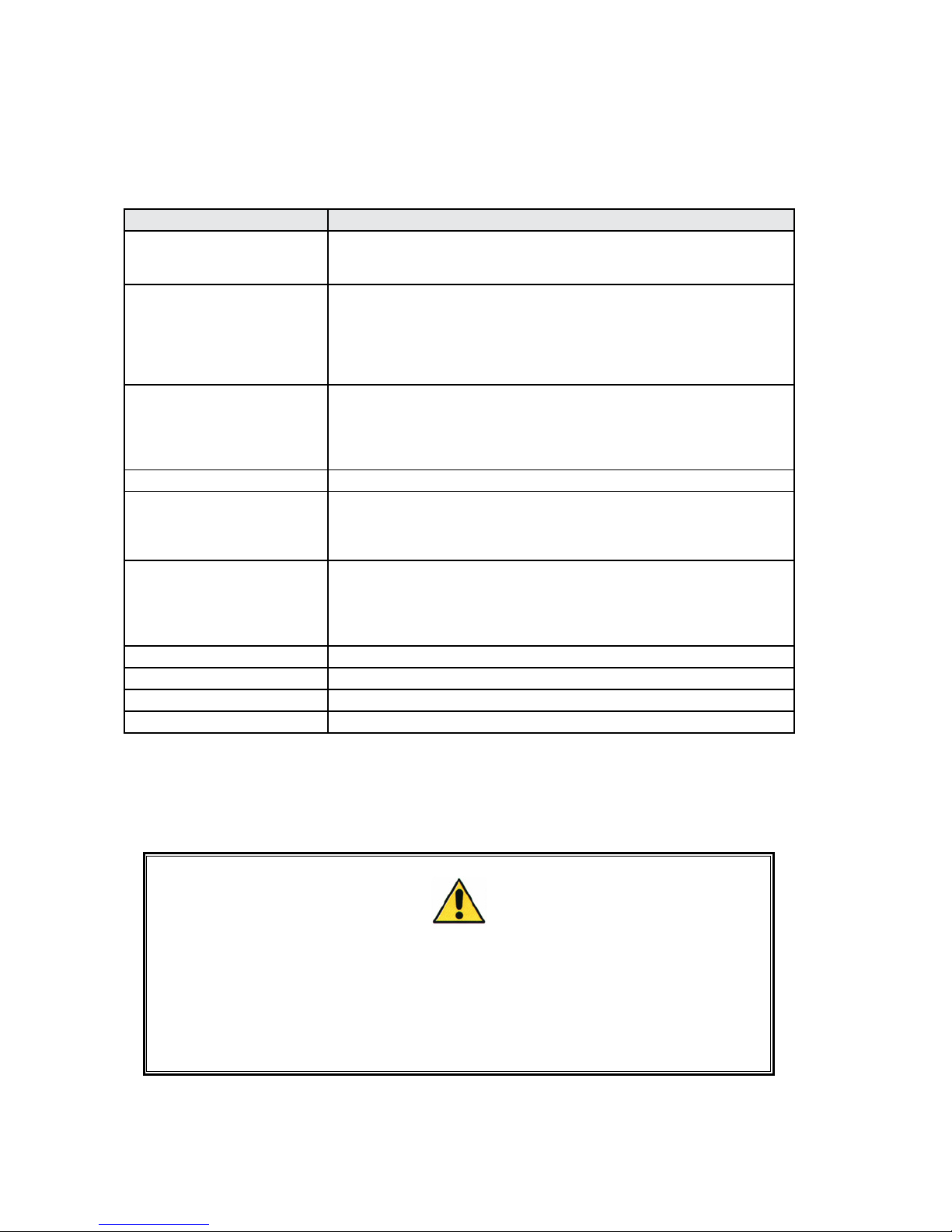
1.1 Description
OPERATIVE MODES
SPEED CONTROL
It is speed piloting utilising a digital reference or an
analogue reference (differential or common mode).
standard
TORQUE CONTROL
It is torque piloting utilising a digital reference or an
analogue reference. This function allows you to control the
current from the drive.
standard
POSITION CONTROL
The positioner can be managed via hardware (by using the
digital inputs) or via RS232 (by using the Axor's Speeder
One interface or another ModBus Master). It supports 32
programmable position proles; a single task or a sequence
of tasks are permitted.
The Homing Procedure is implemented. It uses the signal
coming from the homing sensor and eventually the zero
signal of the encoder.
standard
ELECTRICAL AXIS
(GEARING)
It is possible to pilot the drive with the quadrature signals
of an emulated encoder from a Master drive or with the
quadrature signals of an incremental encoder from a Master
motor (Electrical Axis or Gearing).
standard
PULSE/DIRECTION
It is possible to connect the drive to a stepper-motor
controller, piloting it with the +/-Pulse and +/-Dir signals
(Pulse/Dir Mode).
standard
MULTIDROP RS232
It can work in Multidrop, where the rst drive, connected
via RS232 to the Master PC, is piloted with ModBus
communication, while the other drives are piloted with the
duplication of commands using the CanBus interface.
optional
RS485 INTERFACE
It is possible to communicate with two or more drives by
using the RS485 interface.
optional
CANBUS
It can be congured and controlled using CanBus. It
supports the following Can Open protocols:
• part of the DS301-V4.02
• part of the DSP402-V2.0
optional
Notes:
• The current controller is vectorial with sampling time of 62,5µs.
The velocity and position loop both work with sampling time of 250µs.
• The current commutation is sinusoidal.
FEEDBACK
ENCODER incremental encoder signals + hall signals standard
RESOLVER 2, 4, 6, 8 pole optional
The Magnum400
TM
is a digital drive capable of piloting both rotary AC brushless motors and linear
motors, up to 30Nm. It can be supplied by a 3-phase voltage equal to 400 or 480Vac.
Page 7
7
AXOR Industries Service Manual Magnum400
TM
ver.2 rel.05/'15
1.1 Description
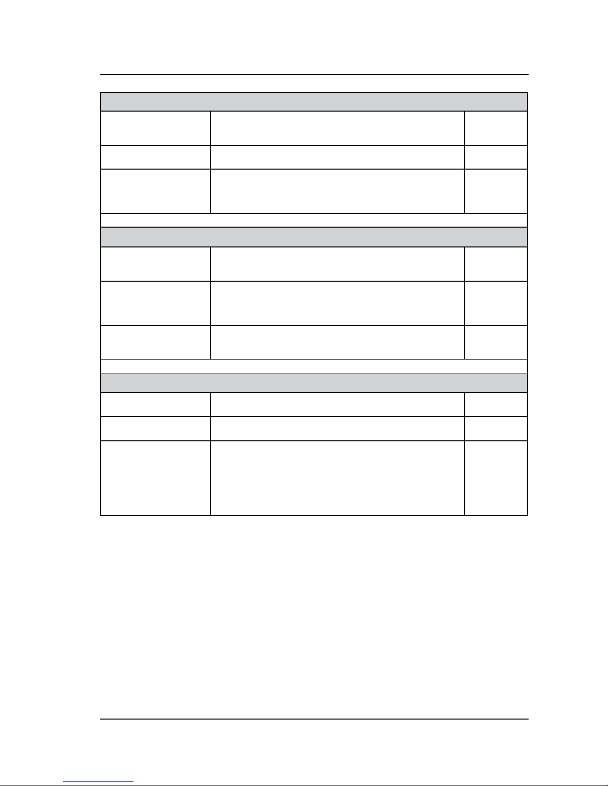
DIGITAL INPUTS/OUTPUTS
9 DIGITAL INPUTS
They are programmable for: the limit switch, the holding
brake, the homing and positioning procedures, the emergency stop, the reset alarm, etc.
standard
2 programmable
DIGITAL OUTPUTS
They can be used to send messages from pre-programmed
functions of the drive.
standard
EMULATED ENCODER
OUTPUTS
There are 6 pins dedicated to emulated encoder with
different programmed ratios (1/2, 1/4, 1/8, 1/16, 1/32,
1/64, 1/128) between output pulse/rev and encoder/
resolver ones.
standard
ANALOG INPUTS/OUTPUTS
1 ANALOG
COMMON MODE
INPUT (TPRC)
It is used for controlling the current from the drive. standard
1 ANALOG
DIFFERENTIAL or
COMMON MODE
INPUTS (+/-Vref)
It is used for piloting the drive with an analogue speed
reference from an external controller.
standard
2 programmable
ANALOG OUTPUTS
They allow you to visualise by the oscilloscope some of the
drive’s measurement values (for example: the velocity, the
Iq current, etc.).
standard
GENERAL FEATURES
KEYPAD
Four buttons (UP-DW-MODE-SET) allow the manual
insertion of data without using a PC.
standard
DISPLAY
A display with 5 characters visualises: the inserted
values, the drive’s status, the alarms.
standard
SPEEDER ONE
SOFTWARE
INTERFACE
It allows you to set and manage all drive’s parameters by
using a PC connected to the drive.
The communication between the drive and PC is done by a
RS232 cable using the ModBUS protocol.
The software works on the following operating systems:
Windows 98, Windows 2000, Windows XP.
standard
Page 8

8
AXOR Industries Service Manual Magnum400
TM
ver.2 rel.05/'15
1.1 Description
HOLDING BRAKE
The drive has circuitry that allows the control of the electromechanical brake integrated in the motor, which can
be used with motor not running, for blocking the motor's
axis.
The drive supplies the brake with +24Vdc. It can be exter-
nally managed by the user or automatically by the drive.
optional
EMI
FILTER
The drive is equipped with an integrated EMI anti-distur-
bance lter at the 3-phase power supply input and with
another EMI anti-disturbance lter at the auxiliary +24V
power supply input.
standard
REGEN CIRCUIT standard
EXPANSION CARDS
There is a slot for expansion card to implement additional
features.
optional
SAFETY
SAFETY
The converter is protected from short circuitry, the Max/Min
Voltage, the drive I
2
t , the Motor I2t , etc.
When there is an alarm the "Relè OK" contact opens and the
motor is stopped, or a message is visualised on the display
without compromising the system's functioning.
standard
BLACK-OUT
DYNAMIC BRAKE
FUNCTION
It stops the motor when there is a black-out. optional
EQUIPMENT
a drive serie Magnum400
TM
standard
terminals: M1, M2, M3, M4, M5
Service Manual
a CD-ROM with Speeder One software interface and all enclosures to service
manual
Motor inductance, 3x1.2mH, for cables over 20/25 meters in length
optional
an external braking resistor (500W or 1000W)
CBLS cable for motor feedback signal, encoder/resolver (meter multiple)
CBLS power cable for motors series SuperSAX;
motors series SuperSAX
All optional features have to be requested by using the proper ordering code (see "1.5 Product plate
and Ordering code").
Page 9

9
AXOR Industries Service Manual Magnum400
TM
ver.2 rel.05/'15
1.2 General view Magnum400
Display and KeyPad
(J1 Connector)
Encoder or Resolver
signals
(M5 Connector)
Motor, brake and
braking circuit
connections
(M3 Connector)
Auxiliary power
supply +24Vdc
(M4 Connector)
Main supply
(J5 Connector)
RS232 comunication
(M2 Connector)
Analog and Digital
Inputs/Outputs
(J3-J4 Connectors)
Can BUS or
RS485 comunication
(M1 Connector)
Encoder emulation,
Pulse/Dir signals
Page 10

10
AXOR Industries Service Manual Magnum400
TM
ver.2 rel.05/'15
1.3 Technical Data
Nominal Data
Nominal Voltage Vac
Three phase: 3x480Vac +10% max, 3x400Vac -10%, 50/60Hz
(Single phase permetted for setup only)
Min/Max dc bus
voltage
Vdc
400Vac 480Vac
400Vdc min ÷ 800Vdc max 500Vdc min ÷ 870Vdc max
Auxiliary power
supply
(for back up)
Vdc +24Vdc (0%, +15%) - 1Adc (3Adc with brake)
Size 1,5/3 3,5/7 7/14 10/20 14/28 20/40
Nominal Current Arms 1,5 3,5 7 10 14 20
Peak current for
5 sec.
Arms 3 7 14 20 28 40
Dissipation at
nominal current
W 30 42 56 88 165 195
Dissipation with
output stage
disabled
W 20
PWM output
frequency
kHz 8
Control signals
Optoisolated digital inputs +24Vdc - 7mA (PLC compatible)
Optoisolated digital outputs +24Vdc - 50mA (PLC compatible)
Analog programmable outputs ±10V (±5%)
A common mode analog input (TPRC) ±10V max, 10kOhm input resistance
A differential or common analog input
(+/-Vref)
±10V max, 40kOhm input resistance
Pulse/Dir digital inputs +5V, optoisolated, max. frequency 250kHz
Emulated encoder outputs
V
OH
=2.5V min - IOH=-20mA
VOL=0.5V max - IOL=20mA
Braking Resistance
Internal Resistance
200W - 66Ohm size: 1.5/3, 3.5/7, 7/14
200W - 33Ohm size: 10/20, 14/28, 20/40.
External Resistance
500W - 66Ohm size: 1.5/3, 3.5/7, 7/14.
500W - 33Ohm size: 10/20, 14/28, 20/40.
1000W - 33Ohm +33Ohm 500W size: 1.5/3, 3.5/7, 7/14.
1000W - 66Ohm // 66Ohm 500W size: 10/20, 14/28, 20/40.
Set point values
400Vac 480Vac
695Vdc min ÷ 735Vdc max 815Vdc min ÷ 845Vdc max
Page 11

11
AXOR Industries Service Manual Magnum400
TM
ver.2 rel.05/'15
Motor encoder inputs
Encoder supply
+5V @ 220mA (±5%)
Differential encoder inputs
line receiver
AM26LS33
Differential hall signal inputs
line receiver
AM26LS33
Encoder max. frequency
250kHz
External Protections (fuses or similar)
Size 1,5/3 and 3,5/7 7/14 and 10/20 14/28 and 20/40
Power supply (F
2
) 6A T(Time Lag) 10A T 20A T
Auxiliary power
supply (F
3
)
6A T
External braking
resistor (F
4
)
4A F(Fast) 6A F 6A F
1.3 Technical Data
Page 12

12
AXOR Industries Service Manual Magnum400
TM
ver.2 rel.05/'15
1.4 Mechanical Dimension
Dimension in: [mm]
UP
MODE DWN SET
A
A
B
B
73,5
270
247
284
223
33
UP
MODE DWN SET
NOTE:
The M1 and M2 connectors are located
under the plastic cover.
To open it, push the cover on the
borders (see A), move it down and
remove it (see B).
Mechanical specications
External dimensions mm 284 x 223 x 73,5
Size 1,5/3 3,5/7 7/14 10/20 14/28 20/40
Weight Kg 4,2 4,6
Page 13

13
AXOR Industries Service Manual Magnum400
TM
ver.2 rel.05/'15
1.5 Product plate and Ordering Code
On the side of each Magnum400TM there is a product plate like the following:
To order a digital drive serie Magnum400
TM
refer to this ordering code:
Nominal and peak
output current (in
Ampere RMS)
Power
supply
Protection
rating
Environmental
temperature
range
"Cod" is an internal production
code. Use this number for any
enquires.
The "Part. No" gives others descriptive codes about the drive and the
settings.
TYPE: MAGNUM-400-7/14-RX-S-D-1000-EC-EC-RD
ADJ: 7/14A 3000 Rpm Enc
Data 20/09/2004 Ord: 0981/2004 Cod. 93759999
M400 - 20/40 - RXX - S - RO - 0 0 0 0 0 X - 00 - Sxxx
Dumping size:
RXX = Internal standard resistor
R5 = 500W external resisor (opt)
66Ω (for 1.5/3 to 7/14)
33Ω (for 10/20 to 20/40)
R10 = 1000W external resistor (opt)
33Ω + 33Ω da 500W (for 1.5/3 to 7/14)
66Ω // 66Ω da 500W (for 10/20 to 20/40)
Size: 1.5/3, 3.5/7, 7/14, 14/28, 20/40
Drive Model
Protection:
S = Standard
T = Tropicalized
Feedback:
RO = Resolver
EC = Commutation encoder
ER = Encoder or Resolver (both)
Expansion cards:
00 = Not present (std)
Additional features:
0 0 0 0 0 X
CBMD: CanBus + Multidrop Interface
1= Present (opt)
0= Not Present (std)
Not in use
Not in use
RXDB: Black Out Dynamic Brake
1= Present (opt)
0= Not Present (std)
R485: RS485 Interface
1= Present (opt)
0= Not Present (std)
Specic number presence (opt):
S xxx
001÷999=specic number
HBD: Holding Brake Drive
1= Present (opt)
0= Not Present (std)
Page 14

14
AXOR Industries Service Manual Magnum400
TM
ver.2 rel.05/'15
Page 15

15
AXOR Industries Service Manual Magnum400
TM
ver.2 rel.05/'15
Chapter 2
Installation
2) Installation
2.1 General Advices 16
2.2 Positioning 19
2.3 Environmental conditions 20
2.4 Cables 21
2.5 Connection to ground and earth 22
2.6 Note about cable shielding 23
2.7 Base installation procedure 24
2.8 Example of base connection 25
2.9 Supply connections 26
2.10 Motor power connection 27
2.11 Relè OK and regen resistance connections 28
2.12 Digital inputs connection 30
2.13 Digital outputs connections 31
2.14 Analog outputs connections 32
2.15 Analog inputs connections 33
2.16 Emulated encoder outputs connection 34
2.17 Pulse/Dir inputs connections 35
2.18 Feedback signals connections 37
2.19 Multidrop connection 39
2.20 Canbus connection 40
2.21 RS485 connection 41
2.22 Magnum400TM power up 42
2.23 Motor Test 43
Page 16

16
AXOR Industries Service Manual Magnum400
TM
ver.2 rel.05/'15
2.1 General Advices
During the transport of the drive respect the following indications:
• the transport must be made by qualied personnel;
• avoid shocks;
• the temperature range must be between -25°C and +55°C;
• the max. humidity must be 95% (without condensation);
• The converters contains elements which are sensitive to electrostatic discharges. These elements
can be damaged by careless manipulation.
Discharge static electricity from your body before touching the converter.
Avoid contact with material that insulates well (synthetic bres, lms of plastic material and so
forth).
• we suggest to check the motor condition at its arrival to survey eventual damages.
Transport
The unused drives must be storage in an environment having the following characteristics:
• temperature from -25°C to +55°C;
• max. relative humidity 95% (without condensation);
• max. time with the drive powered off (without supply connections):
drive having a power supply ≥ 220VAC 1 year
drive having a power supply ≤ 145VAC (200VDC) 2 years
After this time, before enable the drive, it is necessary activate the capacitors following this procedure:
remove all electrical connections, then supply the input terminals of the supply with the main voltage
(three phase or single phase) for 30 minutes.
In details:
- for the drive having a power supply equal to 380VAC: power it by using a single phase (or three
phase) supply equal to 220VAC;
- for the drive having a power supply equal to 220VAC: power it by using a single phase (or three
phase) supply equal to 110÷130VAC.
In order to avoid this procedure, we suggest to power on the drive with its rated voltage for 30 minutes,
before the max. time is reached.
Storage
The drives does not need maintenance.
Otherwise:
• if the casing is dirty: clean it with isopropanol or similar;
• if the drive is dirty: the cleaning is reserved to the producer;
• if the fans are dirty: clean them by using a dry brush.
Maintenance
The disposal should be carried out by a certied company.
Disposal
Page 17

17
AXOR Industries Service Manual Magnum400
TM
ver.2 rel.05/'15
• This manual is exclusively addressed to technical personnel with the following requirements:
- Technician with knowledge on movimentation of elements sensitive to electrostatic
discharges (for the transport).
- Technician with appropriate technical training and with vast knowledge on electrotech-
nics/drive technical eld (for the installation and operation of servodrives).
Using the drive incorrectly can injure people or damage things. Fully respect the technical
data and indications on connection conditions.
• As well as the points described in this manual, current regulations regarding safety and accident
prevention must be followed in order to prevent accidents and residual risks.
• The user must analyse possible machine risks and take the necessary measures to avoid injuries to
people and damage to things because of unpredictable movements.
• The converters contains elements which are sensitive to electrostatic discharges. These elements can
be damaged by careless manipulation.
Discharge static electricity from your body before touching the converter.
Avoid contact with material that insulates well (synthetic bres, lms of plastic material and so
forth).
• During operation, the converter surface can become hot. Protect the user from accidental contact
and keep the indicated distances from all objects.
• Never loosen electrical connections while the servoampliers are being powered.
The appropriate terminals of the drive must always be connected to earth as instructed in this manual.
After having disconnected the converters from the supply current, always wait at least 5 minutes before
touching the powered components (e.g. contacts) or loosening connections.
• Switch off the converter and wait at least 5 minutes before opening it. Remove the fuses or switch
off the main switch before removing the drive. When opening, place the converter on a surface that
does not belong to the electrical panel.
• The residual charges in the capacitors can remain at a dangerous level for up to 5 minutes after disconnection from the mains. Measure the voltage at the intermediate circuit (+AT/-AT) and wait until
it is below 15V.
• The command and power connections can still hold current even when the motor has stopped.
• The Magnum400TM is equipped with electronic protections that deactivate it in case of irregularities.
The motor, as a result, is not controlled and can stop or go into neutral (for a time determined by the
type of system).
• During installation, avoid letting any residue with metallic components fall inside the drive.
2.1 General Advices
Security standard
Page 18

18
AXOR Industries Service Manual Magnum400
TM
ver.2 rel.05/'15
• Protect the converter from excessive mechanical vibrations in the electrical box.
• Check that the main supply and the nominal current are coherent with the rating of the drive. Be
sure that the voltage between the connectors L1-L2-L3 is not greater than 10% of the nominal values.
An excessively high voltage causes the breakdown of the load circuitry and of the drive.
• The Magnum400
TM
is equipped with an integrated EMI anti-disturbance lter at the 3-phase power
supply input and with another EMI anti-disturbance lter at the auxiliary +24V power supply input.
Being implicit to lter operation the deviation towards earth or mass of the undesired frequencies,
ensure that these devices can produce leakage currents towards earth, which are measurable in milliAmpers. Please remember that "leakage currents" must be considered when settings differential
devices in order to avoid useless interventions.
For safety reasons connect the prepared terminal to earth before powering the drive. Incorrect con-
nections make lter operation unreliable.
2.1 General Advices
Page 19

19
AXOR Industries Service Manual Magnum400
TM
ver.2 rel.05/'15
The Magnum400TM is made to be xed vertically to the bottom of the electrical box in order to
guarantee reliable cooling, respecting the following distances:
2.2 Positioning
Note: Arrange the power components (converters, main's lters, resistors, terminals, ... ) in bins of
the electrical panel different from those reserved to the command or control systems (PLC, PC, CNC,
regulators, ...). This improves the level of immunity to interference of the system.
UP
MODE DWN SET
UP
MODE DWN SET
UP
MODE DWN SET
30
(1.18)
30
(1.18)
30
(1.18)
30
(1.18)
Ecc.
270
(10.62)
45
(1.77)
45
(1.77)
mm
INCHES
Cable duct
Cable duct
Conductive mounting panel
(zinc-coated)
The drive must be afxed
utilizing 2 or 4 socket
head screws DIN 912,
M5, paying attention that
the dissipating surface
and the mounting panel
maintain as much contact as possible, in order
to guarantee maximum
thermal dissipation.
Page 20

20
AXOR Industries Service Manual Magnum400
TM
ver.2 rel.05/'15
During the storage and the installation respect the followings environmental conditions:
2.3 Environmental conditions
Condizioni ambientali
Storage temperature -20°C...+55°C
Working environmental temperature
From 0°C to +45° C (no derating).
From +45°C to +55°C the drive must be derated
2.5%/°C in reference to nominal and peak current.
Humidity From 10% to 85%
Altitude
Up to 1000m without restriction.
From 1000 to 2500m of altitude the converter must be
derated in the output current of 1.5% every 100m.
Enclosure protection IP20
Pollution level
LEVEL 2 (Norm EN60204/EN50178)
The drives are designed to be utilized in an electrical
box protected against the inltration of polluting agents
such as water, oil, conductive dust and others.
Notes:
• The electrical box must have suitably ltered air vents.
Leave the necessary space both above and below the converters.
• Periodically check drive case and fans for excess dust or dirt, that could interfere with the correct
dissipation of the drive.
Page 21

21
AXOR Industries Service Manual Magnum400
TM
ver.2 rel.05/'15
The following table illustrates the technical characteristics of all cables:
Cables (as norm EN60204)
Type Section Notes
for the
Main Supply
1.5mm
2
/15AWG
drive size: 1.5/3, 3.5/7, 7/14
Always insert a power relay or a thermal
magnet on every phase of the products
power supply.
2.5mm
2
/14AWG
drive size: 10/20, 14/28, 20/40
for the
Auxiliary
Supply
1.5mm
2
/15AWG
Connect the 0V of the auxiliary supply to the
ground bar.
for the
Motor's Brake
0.75mm
2
It must shielded.
for the
Motor's Power
1.5mm
2
/15AWG
drivesize: 1.5/3, 3.5/7, 7/14
It must be shielded.
It must have a capacity of ≤150pF/m.
In the conguration without lter, the cable
can reach a maximum length of 20/25m. If
the length exceeds 20/25m, insert an Axor
3x1.2mH lter.
2.5mm
2
/14AWG
drive size: 10/20, 14/28, 20/40
for the
Control signals
and
I/O signals
from PLC/CNC
0.5mm
2
/20AWG See "2.6 Note about cable shielding"
for the
Encoder signals
0.25-0.35mm
2
/
22-24AWG
It must be shielded.
It must have a capacity less than 120pF/m.
for the
Resolver signals
0.25-0.35mm
2
/
22-24AWG
for external
resistor
1.5mm
2
/15AWG
The cable must be as short as possible.
If the cable length is greater than 20/30cm,
it must be twisted and shielded. The shield
must be connected to ground on both ends,
utilising u-clamps to the zinced panel of the
electrical box.
for the RS232
communication
0.22mm
2
/24AWG or
0.34mm2/22AWG
The length of the cable must be equal to or
less than 2.5m.
It must be connected when the main supply
and the auxiliary supply are both powered
off.
It must have a capacity less than 160pF/m.
for the
CanBus
communication
0.25mm
2
/0.34mm
2
Cable capacitance: max 60 nF/km.
Impedance characteristics : 100...120Ω.
Lead resistance (loop): 159,8 Ω/km.
The length depends upon the transmission
speed:
• 1000kbit/s 20m max;
• 500kbit/s 70m max;
• 250kbit/s 115m max.
Note:
• Avoid crossing, overlapping and twisting cables together. If it is absolutely necessary to cross them,
do so at 90°.
• On request Axor provides motor signal cables series encoder or resolver for motors series Super-
SAX.
2.4 Cables
Page 22

22
AXOR Industries Service Manual Magnum400
TM
ver.2 rel.05/'15
2.5 Connection to ground and earth
Make sure that the servodrive and the motor are connected to earth in accordance with the current
norms.
This connection must be done by using a copper bar, mounted on insulating supports, as illustrated
below:
l Bar's section
0,5 ...1 m 5x40 mm
1 ... 2 m 5x50 mm
then follow these indications:
1. Connect to the ground bar:
the earth power terminal of the drives;
the CHASSIS of all drives;
the DGT-IN RTN pin of the digital inputs for each drive;
the 0V of the auxiliary supply;
the internal zero voltage of the CNC;
the earth terminals of the PLC/CNC frames;
2. Connect the ground bar to the zinced panel of the drive by using a screw, then connect that
screw to earth.
3. Connect earth to the motor's carcass.
Ground
bar
l
Connection to
earth
PE
Symbol Description
It suggests a conductive connection as much as possible to the chassis, or the heatsink, or the mounting panel of the electrical box.
It refers to the earth connection.
It refers to the connection of the shield to the drive's carcass as illustrated on page
23.
It refers to the connection of the shield to the connector's metal ring.
Page 23

23
AXOR Industries Service Manual Magnum400
TM
ver.2 rel.05/'15
2.6 Note about cable shielding
The conductor of the analogic signal must be twisted
and shielded, and the shield must be connected to
ground as illustrated below:
Control signal cables
Motor cables
The shield of the motor cable (power and signal cables) are connected as follows:
• drive side (20:50cm) remove the outside sheath and x shield to the zinced pannel, by using a
u-clamp (Axor's cables have incorporated u-clamp):
Note:
• To reduce the capacitive and inductive coupling, these cables must be run keeping a distance of more
than 30cm from the power cables (10 cm if they are shielded).
• If it is absolutely necessary to cross the control cables with the I/O's, do so at 90°, in order to reduce
the effect of the magnetic elds.
• motor side the shield is internally connected to the metal ring of the motor connector, thus to
earth through the motor's carcass.
Remove the outside sheath and
afx the shield to the dedicated
retainer rings, by using plastic
clamps.
Chassis: Connect the
screw to the ground
bar.
Page 24

24
AXOR Industries Service Manual Magnum400
TM
ver.2 rel.05/'15
This procedure must be done only by qualified personel which are familiar with drives. If
you need more information contact Axor.
a) Power off all the supplies of the electrical box.
b) Verify:
the drive-motor coupling the stall current (I
o
) of the motor should be equal to/or greater
than the nominal output current of the drive;
the positioning of the drive into the electrical box;
the pollution level and the ventilation;
the connection to earth of the electrical box where the drive is installed (see "2.5 Connection
to ground and earth").
c) Execute the wiring following this order, avoiding that wiring's pieces, cables, wires, screws, conduc-
tive objects, etc. do not enter into the drive through its slits:
1- First connect earth.
2- Connect the cables for the motor's power (U, V, W) and the lter 3x1.2mH, if the cable
length is greater than 20/25m.
3- Connect the earth of the motor's power (PE) and, if necessary, connect the cables of the
electromechanical brake.
4- Connect the external shield of the motor's cable: it must be shielded utilising a u-clamp to
the zinced panel of the electrical box (see "2.6 Note about cable shielding").
5- If the internal braking resistor is used, insert a bridge between pins INT and -AT.
If an external braking resistor is used, connect it between pins EXT and -AT by using a cable
as short as possible. If the cable length is greater than 20/30 cm, the cable must be twisted and
shielded, besides the shield must be connected to ground on both ends utilising u-clamps to the
zinced panel of the electrical box.
6- Connect the motor's feedback cable to the drive's J1 connector
7- Connect the main power supply cable (L1-L2-L3) and the earth cable (PE).
Always insert a power relay or a thermal magnet on every phase of the products power
supply.
8- Connect the auxiliary supply cable (+24V).
Use an external power supply, that must be stabilized and galvanically isolated from the main
supply.
9- Connect the PC to the drive utilising the RS232 cable.
10- Supply the drive with the auxiliary supply and then main supply following the procedure
illustrated at the end of the chapter.
11- Open the Speeder One interface.
12- Execute the tests on the drive and the motor.
In the following page there is an example of a basic connection.
2.7 Base installation procedure
Page 25

25
AXOR Industries Service Manual Magnum400
TM
ver.2 rel.05/'15
2.8 Example of base connection
Example of base connection:
L1
L2
L3
L1
L2
L3
ENABLE
DGT-IN2
AN.OUT1
DGT-IN RTN
GROUND BAR
F
2
MAGNUM 400
SUB-D
9 pin
J5
J4/J3
Rj45
RS-232
-AT
-AT
M4
+AT
+AT
4
5
6
7
1
2
3
PE
8
M3
+24V
2
+24VDC
0V
External Auxiliary
Voltage
CHASSIS
M1
+VREF
DGT-IN3
DGT-OUT1
OUT1-RTN
DGT-OUT2
OUT2-RTN
CHA+
CHA-
CHB+
CHB-
CHZ+
CHZ-
PGND
PULSE(+)
PULSE(-)
DIR(+)
DIR(-)
M2
-VREF
AGND
DGT-IN4
DGT-IN5
DGT-IN6
DGT-IN7
DGT-IN8
DGT-IN9
TPRC
AN.OUT2
AGND
RELE' OK
RELE' OK
+V
-V
30V
AC/DC - 500mA max
4
5
6
7
1
2
3
8
12
13
14
15
9
10
11
4
5
6
7
1
2
3
8
12
13
14
15
9
10
11
16
17
18
19
A
A
A
PE
A
Cap 2.11
Cap 2.9
Mains Earth
Cap 2.9
F
3
J1
7
4
5
6
+
M5
1
2
3
-
+
-
Motor
Holding Brake
(OPTIONAL)
B
Motor
Feedback
SUB-D
25 pin
B
Cap 2.18
Cap 2.10
-AT
INT
EXT
Cap 2.11
Cap 2.14
Cap 2.15
Cap 2.12
Cap 2.15
Cap 2.17
Cap 2.16
Cap 2.13
Regen Resistance
V
U
PE
W
V
U
PE
W
8
9
0V
1
A
A
CAN BUS/RS485
Cap 2.19, 2.20 and 2.21
3
N.C.
Page 26

26
AXOR Industries Service Manual Magnum400
TM
ver.2 rel.05/'15
2.9 Supply connections
AUXILIARY SUPPLY +24Vdc
Note:
• Always insert a power relay or a thermal magnet on every phase of the products power
supply.
• If a power supply between 400V and 480V is utilized and ground protection is not present, or there
is an asymmetrical grounding system, an isolation transformer is required.
The nominal power of the transformer is calculated by adding the various wattage of each motor:
Pt = Pn+Pn+Pn+...
Pt= nominal power of the transformer (VA)
Pn= nominal power of each motor (VA), which can be calculated in this way:
Pn = n x Cn / 9,55
Pn=nominal motor power (W)
n= motor speed (rpm)
Cn= motor nominal torque (Nm)
POWER SUPPLY
Note:
• Accepted voltage: +24VDC (0%/+15%);
• current required for the external supply: 3A (motor with brake);
• current required for the external supply: 1A (motor without brake);
• we suggest to insert the F3 (6A T) fuse;
• we suggest to connect the 0V of the external supply to the ground bar .
External supply
+24VDC
+24V
0V
L
L
DC
AC
3
1
PE
+24V
0V
F
3
2
F
2
F
2
F
2
MAGNUM400
TM
M3
L1
L2
L3
AC
DC
4
1
2
3
PE
F
2
L1
L2
L3
M4
MAGNUM400
TM
3/PE
50/60Hz
400...480V
F
2
F
2
Page 27

27
AXOR Industries Service Manual Magnum400
TM
ver.2 rel.05/'15
EXT
INT
-AT
U
V
W
PE
B+
B-
Power
L
MAGNUM400
TM
M5
M
1(N.C.)
2(N.C.)
3
4
5
6
7
8
9
2.10 Motor power connection
MOTOR POWER + MOTOR HOLDING BRAKE
WITHOUT brake
WITH brake
OPTIONAL
(vedi nota a)
(see note a)
(vedi nota b)
(see note b)
b- The earth connection of the power cable’s shield must be made on
the zinc-coated panel (using a u-clamp) near the drive (20-50cm).
Motor side: the shield is connected to connector's metal ring, so it is
connected to ground through motor's carcass.
Note:
a- Use 3x1.2mH - 20Arms lter series for connections with cables longer than 20/25 meters.
Technical characteristics of brake outputs:
Output Voltage: +24VDC [0%, +15%].
Maximum available current: 3A.
EXT
INT
-AT
U
V
W
PE
B+
B-
Power
L
MAGNUM400
TM
M5
M
1
2
3
4
5
6
7
8
9
Page 28

28
AXOR Industries Service Manual Magnum400
TM
ver.2 rel.05/'15
2.11 Relè OK and regen resistance connections
REGEN RESISTANCE connection
INTERNAL resistance
EXTERNAL resistance
The cable must be as short as possible.
The resistances must be connected to the
zinced pannel utilising two screws.
If the cable length is greater than
20/30cm, it must be twisted and shielded.
The shield must be connected to ground
on both ends, utilising u-clamps to the
zinced panel of the electrical box.
Attention: The internal braking
circuit is enabled only if a bridge is
present between pins 7 (-AT) and
8 (INT) on the M5 connector.
RELE' OK connection
EXT
INT
-AT
U
V
W
PE
B+
B-
MAGNUM400
TM
M5
1
2
3
4
5
6
7
8
9
EXT
INT
-AT
U
V
MAGNUM400
TM
M5
5
6
7
8
9
F
4
PE
18
19
M2
MAGNUM400
TM
OPTIONAL
It is normally open when the drive is not supplied;
it is normally closed when the drive is supplied and
it has not active alarms.
30VAC/DC - 500mA max
Page 29

29
AXOR Industries Service Manual Magnum400
TM
ver.2 rel.05/'15
2.11 Relè OK and regen resistance connections
100
100
100
100
80
100
100
100
100
100
(mm)
(mm)
EXTERNAL BRAKING CIRCUIT
Drive
Size
[A]
R5
Resistor
P
tot
=500W
Connection
R10
Resistor
P
tot
=1000W
Connection
1,5/3
1 resistor
66 ohm
500W
2 series
resistors
33 ohm
500W
3,5/7
7/14
10/20
1 resistor
33 ohm
500W
2 parallel
resistors
66 ohm
500W
14/28
20/40
Notes:
• The temperature of the zinced panel of the electrical box can be higher than 200°C.
• Do not mount the resistor on surfaces which can be damaged by heat.
• If the resistors are mounted externally, protect them.
• Respect the following distances and shieldings:
• Axor external resistances have the following dimensions:
-AT (7)
E
XT (9)
R=33ohm, P=500W
-AT (7)
E
XT (9)
R=66ohm
P=500W
R=66ohm
P=500W
-AT (7)
E
XT (9)
R=66ohm, P=500W
-AT (7)
EXT (9)
R=33ohm, P=500W
R=33ohm, P=500W
35mm
260mm
400mm
Note: In accordance with the used resistance, internal or external, we recommend to correctly set the
Regen Resistance parameter in the "General Setting" window in the Speeder One interface: internal
(if the internal resistance is used), external (if an external resistance is used).
Page 30

30
AXOR Industries Service Manual Magnum400
TM
ver.2 rel.05/'15
2.12 Digital inputs connection
DIGITAL INPUTS connection
Notes:
• The enable signal should be +24VDC-7mA (PLC compatible). The enable range is between +14V
Min and +30V Max.
• The M2-4 terminal (DGT-IN1 (ENABLE)) is used only as the drive’s enable. If M2-4 is HIGH
(+24VDC) the drive is enabled (without active alarms and if start up sequence, illustrated on paragraph 2.21, is respected); if M2-4 is LOW (0V), the motor is without torque.
ATTENTION: THE DRIVE'S ENABLE/DISABLE, BY USING THE ENABLE INPUT, IS NOT CONSIDERED A
SECURITY FUNCTION.
• The other inputs can be used to activate pre-programmed functions of the drive (for example: limit
switch , electromechanical brake, homing and positioning procedures, emergency stop, etc.).
For a detailed description of the pre-programmed functions see enclosure "Speeder One Interface",
"Additional Features Manual" and "Positioner Manual" on the CD provided with the drive.
• Connect pin M2-13 (DGT-IN RTN) to the ground bar of the system.
DGT- IN RTN
I/O GND
DGT-IN5
DGT-IN1
(ENABLE)
+24VDC
refered to I/O GND
CN
MAGNUM400
TM
M2
4
8
5
6
7
9
10
11
12
13
DGT-IN2
DGT-IN3
DGT-IN4
DGT-IN6
DGT-IN7
DGT-IN8
DGT-IN9
10k
DGT-IN RTN
5V1
DGND
Page 31

31
AXOR Industries Service Manual Magnum400
TM
ver.2 rel.05/'15
2.13 Digital outputs connections
DIGITAL OUTPUT Connection (example)
This digital output can be used to send messages from the pre-programmed function of the drive.
For a detailed description of the pre-programmed functions see enclosure "Speeder One Interface" on
the CD provided with the drive.
Max. load for each output:
50[mA].
Always use a relay with a diode
in parallel.
MAGNUM400
TM
CN
+24VDC
refered to I/O GND
I/O GND
1
2
CN
I/O GND
LOAD
CN
25R
LOAD
I/O GND
M1
25R
3
4
MAGNUM400
TM
1
2
25R
M1
25R
3
4
LOAD
MAGNUM400
TM
1
2
25R
M1
25R
3
4
LOAD
+24VDC
refered to I/O GND
+24VDC
refered to I/O GND
+24VDC
refered to I/O GND
+24VDC
refered to I/O GND
Page 32

32
AXOR Industries Service Manual Magnum400
TM
ver.2 rel.05/'15
ANALOG OUTPUTS Connections
They permit visualisation by oscilloscope of some of the drive’s measurement values.
The two outputs furnish +/-10Volt
as the low scale setting refers to.
They can be set by the Speeder One
interface.
Note: We suggest to connect the shield on both sides: drive side follow the indications illustrated on
paragraph 2.6.
2.14 Analog outputs connections
MAGNUM400
TM
CN
ANALOG1
CN-GND
15
17
180
470n
ANALOG2
16
180
470n
AN-OUT1
AN-OUT2
M2
AGND
Page 33

33
AXOR Industries Service Manual Magnum400
TM
ver.2 rel.05/'15
2.15 Analog inputs connections
DIFFERNTIAL MODE (+/-Vref)
COMMON MODE (+/-Vref)
ANALOG DIFFERENTIAL OR COMMON MODE INPUT (+/-Vref and
TPRC) connection
COMMON MODE (TPRC)
The technical characteristics of TPRC input are as follows:
Voltage: ±10V Max.
Input impedance: 10k ohm.
Note: We suggest connecting the shield on both sides: drive side, follow the indications illustrated on
paragraph 2.6.
The technical characteristics of +/-Vref inputs are as follows:
Voltage: ±10V Max.
Input impedance: 40k ohm.
To change the sense of rotation, apply the positive voltage reference to M2-1, or change the Rotary
Direction parameter in the Speed window (from Positive to Negative).
Note: We suggest connecting the shield on both sides: drive side, follow the indications illustrated on
paragraph 2.6.
+
-
CN
-VREF
+VREF
10K0
10K0
10K0
2K0
2K0
AGND
AGND
1
3
2
CN-GND
10K0
Magnum400
TM
M2
+
-
CN
+VREF
10K0
10K0
10K0
10K0
2K0
2K0
AGND
AGND
1
3
2
CN-GND
M2
Magnum400
TM
Magnum400
TM
+
-
CN
10K0
1K0
1K
TORQUE
REFERENCE
AGND
220p
14
AGND
3
AGND
CN-GND
M2
Page 34

34
AXOR Industries Service Manual Magnum400
TM
ver.2 rel.05/'15
2.16 Emulated encoder outputs connection
EMULATED ENCODER OUTPUTS connection
LINE RECEIVER CN inputs
COMMON MODE CN inputs
Note: We suggest connecting the shield on both sides: drive side, follow the indications illustrated on
paragraph 2.6.
CN-GND
CHA
CHA-
CHB
CHB-
CHZ
CHZ-
R
CN
R
R
RS485
RS485
RS485
PGND
+5V
Drive
PGND
CN-GND
CN
PGND
+5V
CHA
CHB
CHZ
PGND
Drive
CHA-
CHB-
CHZ-
Page 35

35
AXOR Industries Service Manual Magnum400
TM
ver.2 rel.05/'15
2.17 Pulse/Dir inputs connections
PULSE/DIRECTION MODE connection
Logical signal 0/+5V
Logical signal 0/+24V open collector NPN
Note: We suggest connecting the shield on both sides: drive side, follow the indications illustrated on
paragraph 2.6.
Note: We suggest to shield separatelly the couples of cable and to connect the shields together and
to the PLC ground.
12
13
CN
14
15
M1
+PULSE
-PULSE
+DIR
-DIR
MAGNUM400
TM
CN-GND
4k7
220
220
4k7
220
220
11
PGND
12
13
PLC
14
15
M1
+PULSE
-PULSE
+DIR
-DIR
2k2
1/4 W
MAGNUM400
TM
0S
OUT
+24V
0_24V
2n2
4k7
220
220
2n2
0S
OUT
4k7
220
220
0_24V
2k2
1/4 W
+24V
Page 36

36
AXOR Industries Service Manual Magnum400
TM
ver.2 rel.05/'15
2.17 Pulse/Dir inputs connections
ELECTRICAL AXIS (GEARING) Connection
Note: We suggest connecting the shield on both sides: drive side, follow the indications illustrated on
paragraph 2.6.
12
13
MAGNUM400
TM
(Slave)
14
15
M1
A+
A-
B+
B-
MAGNUM400TM
(Master)
M1
5
6
7
8
11
PGND
4k7
220
220
4k7
220
220
PGND
11
Page 37

37
AXOR Industries Service Manual Magnum400
TM
ver.2 rel.05/'15
2.18 Feedback signals connections
ENCODER FEEDBACK connection
CHA+
CHA-
CHB+
CHB-
CHZ+
CHZ-
Motore side
ENCODER
AGND
+5V
PTC MOTOR
PTC INPUT
HALL U+
HALL U-
HALL V+
HALL V-
HALL W+
HALL W-
J1
21
13
5
18
6
19
7
20
10
1
11
2
12
3
4
17
8
+5V
0V
Drive side
270
2K2
100p
2K2
5
6
7
8
9
10
11
12
14
13
15
16
17
2
3
4
AGND
+5V
17 pole connector
(Encoder)
1
9
8
2
10
12
7
3
11
6
4
5
13
14
15
16
17
PE
*
Motor Cable
Drive
Motor
20:50cm
Max 25m
1 2 3 4 5 6 7 8 9 10 11 12 13
14 15 16 17 18 19 20 21 22 23 24 25
J1 connector
Sub-D 25 pole
If the motor has not the thermal protection (PTC MOTOR) you should bridge pins 4 and
17 on the "J1, Sub-D 25 pole" connector of the drive.
Note: The ground connection of the external shield must
be made on the zinc-coated panel (using a u-clamp) near the
drive (20-50cm).
Motor side: the shield is connected to connector's metal ring.
Page 38

38
AXOR Industries Service Manual Magnum400
TM
ver.2 rel.05/'15
2.18 Feedback signals connections
SIN INPUT
COS INPUT
PTC INPUT
PTC MOTOR
4V RMS
25
16
23
14
24
15
4
17
8
13
+ECC
-ECC
+SEN
-SEN
+COS
-COS
Drive side
Motor side
RESOLVER
J1
5
9
3
7
4
8
2
6
AGND
Motor Cable
Drive
Motor
20:50cm
Max 25m
12 pole connector
(Resolver)
1
9
8
2
10
12
7
3
11
6
4
5
PE
*
1 2 3 4 5 6 7 8 9 10 11 12 13
14 15 16 17 18 19 20 21 22 23 24 25
J1 connector
Sub-D 25 pole
OPTIONAL
RESOLVER FEEDBACK connection
If the motor does not have thermal protection (PTC MOTOR) you should bridge pins 4
and 17 on the "J1, Sub-D 25 pole" connector of the drive.
Note: The ground connection of the external shield must
be made on the zinc-coated panel (using a u-clamp) near the
drive (20-50cm).
Motor side: the shield is connected to connector's metal
ring.
Page 39

39
AXOR Industries Service Manual Magnum400
TM
ver.2 rel.05/'15
2.19 Multidrop connection
MULTIDROP connection
OPTIONAL
Notes:
• Connect the rst Magnum400TM to the Master using the RS232 cable (J5 connector); connect each
additional drive with to the drive preceeding it using the Can Bus cables and the J3 and J4 connectors; connect a RESISTOR (120 Ohm, 1/4W) between pins 1 and 2 of the J3 (or J4) connector of
the rst Magnum400TM and another resistor between pins 1 and 2 of the J3 (or J4) connector of the
last drive.
• Axor drives use MODBUS communication protocol specied in the Modicon instructions (see
http://www.modicon.com/techpubs/).
For more information see enclosure "Modbus Manual" on the CD provided with the drive.
120
Ohm
J3
J4
J3
Magnum400 1
1
2
3
CAN H
CAN L
PGND
dc-dc Converter
7
PGND
4
5
6
8
1
2
1
2
3
dc-dc Converter
PGND
7
4
5
6
8
dc-dc Converter
PGND
3
7
4
5
6
8
TXD
2
3
5
J5
MASTER MODBUS
RXD
PGND
J4
1
2
3
dc-dc Converter
7
PGND
4
5
6
8
120
Ohm
Magnum400 2
Page 40

40
AXOR Industries Service Manual Magnum400
TM
ver.2 rel.05/'15
2.20 Canbus connection
CANBUS connection
OPTIONAL
Note:
Connect a RESISTOR (120 Ohm, 1/4W) between
pins 1 and 2 of the J3 (or J4) connector of the last
Magnum400
TM
120
Ohm
1
2
3
J4
J3
J4
J3
MAGNUM400 1
MAGNUM400 2
CAN Server
120
Ohm
CANH
CANL
PGND
dc-dc Converter
7
PGND
4
5
6
8
1
2
3
CANH
CANL
PGND
dc-dc Converter
7
PGND
4
5
6
8
1
2
1
2
3
dc-dc Converter
PGND
7
4
5
6
8
dc-dc Converter
PGND
3
7
4
5
6
8
PGND
Page 41

41
AXOR Industries Service Manual Magnum400
TM
ver.2 rel.05/'15
2.21 RS485 connection
RS485 connection
OPTIONAL
120
Ohm
4
5
3
J4
J3
J4
J3
MAGNUM400 1
MAGNUM400 2
Master
120
Ohm
A
B
PGND
dc-dc Converter
7
PGND
1
2
6
8
4
5
3
A
B
PGND
dc-dc Converter
7
PGND
1
2
6
8
4
5
4
5
3
dc-dc Converter
PGND
7
1
2
6
8
dc-dc Converter
PGND
3
7
1
2
6
8
PGND
Note:
Connect a RESISTOR (120 Ohm, 1/4W) between
pins 4 and 5 of the J3 (or J4) connector of the last
Magnum400
TM
Page 42

42
AXOR Industries Service Manual Magnum400
TM
ver.2 rel.05/'15
The power up of the Magnum400TM must be done following this sequence, in order to save the drive
and the electrical box:
2.22 Magnum400TM power up
Attention: If the DGT-IN1 (ENABLE)
digital input is enabled by the CN before
powering the drive (A), after powering the
drive utilising the auxiliary supply and the
main supply, it is necessary disable and
enable the DGT-IN1 input (B), in order to
enable the INTERNAL ENABLE. If the DGTIN1 is not disabled , then re-enabled, the
INTERNAL ENABLE remains disabled and
the user cannot execute any movement.
1) Power the drive utilising the
auxiliary supply, +24VDC.
2) After 1sec. power the main
supply.
3) the "Relè Ok " contact
closes
(*)
.
4) After 100ms it is possible
to enable the drive utilising
the "Enable" key or the DGTIN1 digital input.
T
T
T
T
AUXILIARY
SUPPLY
MAIN
SUPPLY
RELE' OK
DGT-IN1
(HARDWARE ENABLE)
+24V
+24V
0V
0V
1
0
ON
OFF
1s
50ms
100ms
(1)
(2)
(3)
(4)
T
T
T
+24V
+24V
0V
0V
ON
OFF
1s
DGT-IN1
(HARDWARE ENABLE)
(A) (B)
T
INTERNAL ENABLE
ON
OFF
AUXILIARY
SUPPLY
MAIN
SUPPLY
Attention: If the digital input DGT-
IN1 (ENABLE) is enabled by the CN
after powering the drive utilising the
auxiliary supply, but before powering the
drive utilising the main supply (C), it is
necessary to disable and then re-enable
DGT-IN1 input (D), in order to enable
the INTERNAL ENABLE also. If the DGTIN1 is not disabled then re-enabled, the
INTERNAL ENABLE remains disabled and
the user cannot execute any movement.
T
T
T
MAIN
SUPPLY
+24V
+24V
0V
0V
ON
OFF
AUXILIARY
SUPPLY
DGT-IN1
(HARDWARE ENABLE)
(C) (D)
T
INTERNAL ENABLE
ON
OFF
(*)
It is possible to close the contact after auxiliary supply insertion, setting the "Closed when
ready" function in the "General Settings" window of the Speeder One interface.
Page 43

43
AXOR Industries Service Manual Magnum400
TM
ver.2 rel.05/'15
2.23 Motor Test
This procedure is a guide line for the first power up of the drive-motor system. It must only be executed by technically qualified personnel. If you need more information contact Axor.
1) Follow the basic procedure previously described. ATTENTION: do not apply load to the motor.
2) Install Speeder One interface from CD.
3) Power up the drive: apply the auxiliary supply and then the main supply (follow the procedure
previously described).
4) Open the Speeder One interface clicking on "Axormb.exe" executable le on directory: "C:\Programm\
Axor". The main window "Axor Servo Drive" and the "Select Driver" windows open simultaneously.
On the Select Driver window insert the drive's address (all drives have 1 set as default value), then
click OK.
5) If the drive is "Not congured", it is necessary to open a pre-set connguration le, following this
procedure:
- in the main window select the "File"menu and then "Open";
- in the directory: ...\Axor\Data\Devices\ select a le reference to the coupling drive-motor, then
click on “Open”;
- save load parameters by using "Save Data To EEPROM" icon.
If the drive is congured for a specied motor, it is sufcient to check these parameters:
Main voltage (Main Voltage menu in the main window of the interface)
Number of motor poles (Motor window)
Feedback type(Motor window)
Encoder impulse/rev or resolver n° of poles (Motor window)
Irms current(Current window)
Ipk current (Current window)
Speed Limit (Speed window)
Page 44

44
AXOR Industries Service Manual Magnum400
TM
ver.2 rel.05/'15
2.23 Motor Test
6) If alarm should appear, resolve them before going forward (see chapter 3).
7) Set the operative mode "1: Digital Speed", set a speed reference equal to 100rpm, enable the
drive with the Enable button.
If shaft turns correctly, at teh set speed, without alarms, it is possible to connect the load and cable
the machineè possibile procedere con il collegamento del carico e con il cablaggio della macchina; at
teh contrary, if alarms should be compare or if the behavior should not be as set, we suggest to control
te connections and the settings (eventually contact Axor).
8) Connecting the load to the motor, it shoul be necessary to connect gains of speed loop, following
this procedure:
a- Set the "10: Square wave" operating mode.
b- Set the "Speed_RPM" parameter on the "Analog OUT1" menu.
c- Connect the probe of the oscilloscope on pins AN.OUT1 (speed signal) and AGND (zero sig-
nal).
d- Enable the drive.
e- Adjust the KP and KI gains in a way that you obtain a stable step response in both directions.
Increasing KP decreases the system’s response time; however, the system gets closer to becoming
unstable; therefore, during adjustment increase the KP to the oscillation limit and then reduce until
secure oscillation stoppage.
Increasing KI the steady state diminishes, however increasing the overshoot, therefore after adjusting KP increase KI keeping the overshoot within authorized limits (±10%).
The gure below illustrates some typical oscilloscope tracks:
A) Proportional and integral gains too low. Increase the numerical values of KP and KI.
B) and C) Good proportional and integral gains.
A
B
C
Speed
9) At this point it is possible to set other parameters in reference to the desired operative mode (see
enclosures "Operative modes Manual", "Additional Features Manual", "Speeder One Interface"
available on the CD provided with the drive).
Page 45

AXOR Industries Service Manual MAGNUM400
TM
ver.2 rel.05/'15
45
Chapter 3
Diagnostic
3) Diagnostic
3.1 Display 46
3.2 Alarms 47
Page 46

AXOR Industries Service Manual MAGNUM400
TM
ver.2 rel.05/'15
46
3.1 Display
A display LED visualises: the drive's status, the inserted values, the alarms.
Symbol Description
F
The digital input ENABLE is enabled,
while the digital input set with the
"Ref on" function is disabled.
E
The digital input ENABLE is disabled, while the digital input set with
the "Ref on" function is enabled.
[ ]
The digital input ENABLE and the
digital input set with the "Ref on"
function are both enabled; the motor does not move.
(segment appears rotating in a
clockwise or counter-clockwise
direction)
The rotor is turning in a clockwise
or counter-clockwise direction.
0ı
This appears when the negative limit switch (NSTOP) is interrupted.
0 ı
This appears when the positive limit
switch (PSTOP) is interrupted.
- - -
This appears when the converter
is correctly powered on, the digital
input ENABLE is disabled and there
are no alarms.
24 UP
This appears when there is the
+24VDC auxiliary supply, but not
the main supply.
ALxx
There is alarm xx.
SEF
The Safe Torque Off function is en-
abled (the motor has not torque).
Page 47

AXOR Industries Service Manual MAGNUM400
TM
ver.2 rel.05/'15
47
The table below illustrates all the message errors:
3.2 Alarms
ALARM SOLUTION
AL1
EEPROM alarm
Error while memorising parameter to the drive's EEPROM or reading parameters from drive's Eeprom.
Disable the drive, try to memorise the parameter, then re-enable.
AL2
Overcurrent alarm
Short circuit between U, V, W or towards earth.
Disconnect the power, verify the wiring, then
power up again.
AL3
Drive Temperature alarm
Heat sink temperature too high, >70°C.
Disable the drive, verify:
• the forced ventilation functioning,
• the ambient temperature,
wait until the radiator has cooled off, reset the
alarm then enable the drive.
AL4
Hall alarm
This alarm comes on if one or more of the hall cell's
wires are disconnected.
Disable the drive, verify the cell's wire connection, reset the alarm, then enable the drive.
AL5
Encoder alarm
This alarm comes on if one or more of the encoder
channels are interrupted.
Disable the drive, control the connections, reset
the alarm, then enable the drive.
If the alarm persists contact Axor.
AL6
I
2
t Drive alarm
The internal I2t function has reached the maximum
permitted. The cause could be one of the following:
• the working cycle could be too heavy;
• a possible mechanical block;
• motor phase inversion;
• the electronic brake is not unblocked;
• the amplier's dynamic costants: "KP", "KI" and
"KD", could create useless current oscillation.
It is only a message.
This does not cause the disabling of the drive's
functioning, but it is possible to close the Relè OK
contact during this alarm.
The current is limited to the rated one, set in
"Current" window.
AL7
Motor Temperature alarm
Heat sink temperature too high.
This causes the opening of the Ok Relè contact and
disables the drive.
Disable the drive:
• control the heat sink temperature;
• decrease the dynamic constant if the mo-
tor is vibrating. This situation causes current
oscillation and consequently the overheating
of the motor.
Wait until the motor has cooled off, reset the
alarm, then enable the drive.
AL8
Regenerative Resistance alarm
The value I
2
t energy recovery has reached the maximum allowed.
This causes the opening of the Ok Relè contact and
disables the drive.
Disable the drive:
• check the AC power supply input;
• check that the working cycles are not exces-
sive;
• verify if the motor, going at half speed, shows
the same problem.
Reset the alarm, then enable the drive.
AL9
Min/Max Voltage alarm
Minimum or maximum converter voltage.
See min/max voltage values at "1.3 Technical
Data".
This causes the opening of the Ok Relè contact and
disables the drive.
Disable the drive, wait until the DC power supply
voltage reaches the correct threshold, check the
AC power supply input, then enable the drive.
AL10
Pre-Alarm Recovery alarm
80% of the I
2
t energy recovery value has been
reached.
This does not cause the disabling of the drive.
Check the AC power supply input and the working cycles. This is only a message, it anticipates
the intervention of the "Maximum recovery"
alarm.
Page 48

AXOR Industries Service Manual MAGNUM400
TM
ver.2 rel.05/'15
48
AL12
Resolver alarm
Missing one or more resolver signals.
This causes the opening of the Ok Relè contact
and disables the drive.
Disable the drive, control the resolver's contact, reset the alarm, then enable the drive.
AL14
Following Error
The error between the position reference and the
position feedback exceeds the "Max Position Error" parameter, because the "Max Position Error"
parameter is too small, or the dynamic gains of
the velocity-positioning loop are wrong.
This causes the opening of the Ok Relè contact
and disables the drive.
Disable the drive, check the Max Position Error parameter, check the dynamic gains, reset the alarm,
then enable the drive.
AL15
Limit Switch
The two xed limited positions have both been
disabled or interrupted.
This causes the opening of the Ok Relè contact
and disables the drive.
Disable the drive, check the limit contacts and external connections, then enable the drive.
AL17
Overcurrent regen resistance circuit
Possible short-circuit in the regen resistance circuit.
This causes the opening of the Relè OK contact
and the disabling of the functioning.
Power off the drive, control the short-circuit, then
power on the drive.
AL18
Mechanical Brake
Overcurrent at the internal brake command or
wrong connections.
This causes the opening of the Ok Relè contact
and disables the drive.
Disconnect the power:
• control the external connections;
• control the current absorption of the motor
brake;
• verify the settings of the "Holding Brake" parameter on the "Motor" window;
then power up again.
24 UP
In-rush Bus
This is not an alarm.
Indication of the drive's in-rush phase or the lack
of the main power supply.
AL20
Auxiliary Voltage
Presence of the main supply (L1, L2, L3), but the
auxiliary +24Vdc voltage is missing.
This causes the opening of the Ok Relè contact
and disables the drive's functionability.
Disable the drive, connect the Auxiliary Voltage, and
then re-enable.
AL21
Phasing Error or "Wake & Shake"
The auto-phasing was not successful and causes
the opening of the "Relay OK" contact and blocks
functioning.
Disable the converter and check for friction or mecchanical blockages on the axis.
AL23
Flash Alarm
Errors in reading/writing parameters on the Flash
memory, or Flash memory is empty.
This causes the opening of the Ok Relè contact
and disables the drive's functionability.
Disable the drive, save new values, then
re-enable. If the problem persists contact Axor.
AL24
Can Bus Alarm
Error during communication with CanOpen protocol.
This causes the opening of the Ok Relè contact
and disables the drive's functionability.
Disable the drive, check the cabling and
re-enable. If the problem persists contact Axor.
AL26
Homing Error
Position error too high during the homing procedure.
The motor stops, but it is not disabled.
Check the homing setup, then reset the alarm
using the "Start Homing" function.
3.2 Alarms
Page 49

AXOR Industries Service Manual MAGNUM400
TM
ver.2 rel.05/'15
49
3.2 Alarms
AL27
Encoder Pulse Counting Error
Incorrect counting of the encoder pulses in a mechanical revolution of the motor shaft.
Check the connection of the shields in the green cable.
AL31
Intervention of the "IMMEDIATE STOP"
function.
The drive has detected the possibility of a "Runaway Motor"
It only generates, in Historical Alarm, the massage
"AL5" (ENCODER ALLARM).
AL32
Maximum speed exceeded
The speed value set in the drive was exceeded.
This will generate Historical Alarm "AL32". And sebsequently it will generate "AL31" which will initiate
the Immediate Stop Function.
Page 50

50
AXOR Industries Service Manual Magnum400
TM
ver.2 rel.05/'15
Index
A
Alarms 47
analog common mode input (TPRC) 7, 33
analog differential or common mode inputs (+/-Vref) 7, 33
Analog outputs 7, 32
Auxiliary supply +24Vdc 26
C
Cables 21
Canbus connection 40
Conformity 51
Connection to earth 22
Connection to ground 22
D
Digital inputs 7, 30
Digital output 7, 31
Display 7, 46
Disposal 16
E
EMI lter 8
emulated encoder outputs 7, 34
encoder connection 37
Environmental conditions 20
equipment 8
Example of base connection 25
Expansion cards 8
F
Fuse 11
G
General view 9
H
Holding brake 8
I
installation procedure 24
K
KeyPad 7
M
Maintenance 16
Mechanical Dimension 12
Motor holding brake 27
Motor power 27
Multidrop connection 39
Page 51

51
AXOR Industries Service Manual Magnum400
TM
ver.2 rel.05/'15
Index
O
Operative Modes 6
CanBus 6
electrical axis 6
multidrop RS232 6
position control 6
pulse/direction mode 6
RS485 interface 6
speed control 6
Torque control 6
Ordering code 13
P
Positioning 19
Power supply 26
Product plate 13
Pulse/Dir digital inputs 35
R
Regen resistance 28
Rele' OK 28
resolver connection 38
S
Safety 8
black-out dynamic brake function 8
safety enable function 8
Security standard 16, 17, 18
Shielding 23
Speeder One 7
Storage 16
T
Transport 16
Page 52

52
AXOR Industries Service Manual Magnum400
TM
ver.2 rel.05/'15
Conformity
European directives and norms
The servodrives are "components" that are intended to be incorporated into electrical plant and machines
for industrial use.
When the servodrive is used into machines or plant, the electrical plant/machine must respect the
following directives: EC Machinery Directive (2006/42/EC), EC Directive on EMC (2004/108/
EC), Low Voltage Directive (2006/95/EEC).
The machine/plant manufacturer must examine whether with its machine/plant still further
or other standards or EEC guidelines are to be used.
EC Conformity
The EC mark that is applied to the drives references to the Low Voltage Directive (2006/95/EC)
and EC Directive on EMC (2004/108/EC).
The standard EN 61800-5-1 is applied to ensure conformance with the Low Voltage Directive.
The standard EN 61800-3 is applied to ensure conformance with the EMC Directive.
In reference to noise immunity and noise emission the converters full the requirement to the category
second environment (industrial environment).
If the installation of the drive is carried out differently than described in this manual, the user must
carry out new measures to satisfy the requisites of law.
Page 53

53
AXOR Industries Service Manual Magnum400
TM
ver.2 rel.05/'15
 Loading...